1
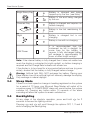
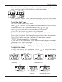
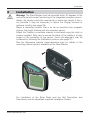
Race Master System
User Guide
Race Master System
EMC Conformance
All Raymarine equipment is designed to the best industry standards for
use in the recreational marine environment. The design and
manufacture of Raymarine equipment conforms to the appropriate
Electromagnetic Compatibility (EMC) standards. Correct installation is
required to ensure that performance is not compromised.
Important
Due to the wireless communication systems used in Micronet
instruments they are only recommended for use on boats up to 18
metres (60 ft.) Before installing to a boat of aluminium or steel
construction, please contact your Raymarine dealer.
Like any other electronic instruments your Micronet system is designed
to serve only as an aid to navigation and it remains the skippers
responsibility to maintain a permanent watch and be aware of
developing situations.
Any attempt to take a Micronet product apart will invalidate the warranty.
The battery may only be replaced by a person trained and approved for
this purpose.
www.raymarine.com
Contents
1
2
3
Information
2
Key Features -
2
Basic Operation
3
2.1
2.2
2.3
2.4
2.5
2.6
2.7
2.8
3
3
3
4
4
5
5
5
Display Information Switching the System On and Off Power Management and Battery Life Sleep Mode Backlighting Keylock Audible Signals and Alarms Safety and Disposal -
Racing Functions
6
3.1
3.2
3.3
3.4
6
6
8
10
Some Definitions and Terminology Improving Race Performance with the Race Master Before the Race During the Race -
4
Advanced Racing Functions
5
Micronet Functions
14
5.1
5.2
5.3
5.4
5.5
5.6
5.7
14
16
16
16
17
18
18
6
7
Chapter and Page Operation Display Modes Depth Pop-up and Depth Shallow Alarm Speed Trim Bar Graph Functionality
Page Hiding Operation with Wind Data on the network -
12
Setup and Calibration
19
6.1
6.2
6.3
6.4
19
20
20
21
Setup and Calibration Organisation Setup and calibration Operation Editing Setup Data Setup Parameter Descriptions -
Seatrial and Calibration
27
7.1
7.2
7.3
7.4
27
28
29
30
Compass Calibration and Alignment Depth Offset Speed Calibration Wind Calibration -
8
Installation
9
Maintenance and Fault Finding
32
9.1 Care and Maintenance 9.2 Fault Finding -
32
32
Specifications
34
Warranty Information
35
www.raymarine.com
31
1
Race Master System
1
Introduction
Key Features
Your Micronet Race Master System provides a unique combination of
features:
Viewable from both sides of the boat
Two LCD displays mounted at an angle to permit viewing from either
side of the boat.
Solar Power
The Micronet Race Master System is powered for life by the
environment. Although feature packed and highly visible in all
conditions, current demand is so low, and the supply so efficient, that
the solar-powered display is self sufficient.
Integrated Heading Sensor
With it's integrated fluxgate compass, the Micronet Race Master acts as
a powerful racing compass; with functions for capturing the mean wind
direction, wind shifts and the starting line bias.
Networked Speed and Depth
Using the networked Hull Transmitter with the depth and speed
transducers, the Micronet Race Master System becomes a complete
navigational and race information system.
Bar Graph display
Both screens of the Micronet Race Master incorporate a bar graph to
permit analogue display of Wind Shift, Speed Trim or Depth.
Networked Data capability
By connecting additional Micronet transmitters (e.g. Wind Transmitter) or
NMEA devices, the Micronet Race Master can display a wide range of
navigational data.
Remote Control capability
By purchasing an optional Raymarine Remote Display, you can control
your Race Master from any location in the boat.
2
www.raymarine.com
Basic Operation
2.
Basic Operation
Important: Ensure that the "Auto Network" procedure described on the
yellow instruction sheet and full Setup and Calibration has been
performed correctly before attempting to use your Micronet Racemaster
System.
2.1
Display Information
2.2
Switching the System On and Off
To switch your Micronet Racemaster System on or off press
seconds.
Switch on
2.3
for 2
Switch off
Power Management and Battery Life
What makes your Micronet Race Master System possible is Raymarine's
revolutionary approach to power management. By reducing the amount
of power being used by the electronics and maximizing the potential of
the sun to provide power, the Micronet Race Master System is capable
of virtually perpetual operation.
Power status is indicated by two icons on the display:
Battery Level
and
Charge Rate
Used together these icons will show the condition of the power supply.
If using the displays at night, power usage can be reduced dramatically
by switching the Backlighting to level 1. If Backlighting is not required on
displays located below decks it is best to set them to "Local"
Backlighting control (see page 25) so that power is not being wasted in
displays which may not be visible from the one being viewed.
www.raymarine.com
3
Race Master System
Bright Sunny Day
Battery is charged and being
topped up by the sun. (see Note)
Battery is low and being charged
by the sun.
Overcast Day
Battery is charged and requires no
further charging.
Battery is low but maintaining it’s
level.
Night
Battery is charged but is not
charging.
Battery is low with no charging.
LOW Power
It is recommended that the
instrument be left in daylight for
some time for the battery to
recover. A fully discharged battery
will recharge in approximately 12
hours of direct bright sunlight.
Note: If the internal battery is fully charged then it does not matter how
much the display is subjected to bright sunlight, no further charging is
required and the Charge Rate Indicator will remain low.
If the display is to be stored for a long period before next use (e.g over
winter), ensure that the battery is fully charged before storage.
Warning: Artificial light WILL NOT recharge the battery. Placing your
Race Master close to an artificial light will seriously damage the display.
Only recharge in natural daylight.
2.4
Sleep Mode
If there is no boat speed or change in heading registered on the system
for a period of 12 hours your Micronet Race Master will switch off to
conserve power. A "POWER SAVE" alarm will sound before the system
switches off. Pressing any button within 10 seconds of the alarm
sounding will allow the system to remain switched on.
2.5
Backlighting
At any stage of the display's operation, press and hold
for 2
seconds to access the lighting control.
Pressing
and
will scroll through the options OFF, 1, 2 and 3
whilst changing the backlighting.
4
www.raymarine.com
Basic Operation
Depending on the display setup (see page 25), backlighting on the
whole system or just the single display will be altered.
Backlighting is automatically switched off in daylight as part of the
display's power saving feature and will not operate in daylight.
2.6
Keylock
The Keylock feature protects from accidental key presses. Keylock can
be enabled or disabled in setup (see page 24), it is disabled by default.
When keylock is enabled, pressing a key causes the unit to give the
unlock key prompt. Press
followed by
to unlock the keys (the
keys will function for one minute, after which the keys will automatically
relock).
2.7
Audible Signals and Alarms
At stages during its operation your Micronet Race Master will beep to
indicate alarms or moments of importance.
Power-up
The display will issue a single beep as it is switched on.
Button Press A single beep is issued each time a button is pressed. A
second beep is issued when a button has been held
down for two seconds.
Timer
A single beep will be issued at each minute of the
countdown.
With 1 minute left to go a beep will sound every 10
seconds.
With 10 seconds to go a beep will sound every second.
Countdown complete will be indicated by a single burst
of three beeps.
Alarm
Continuous bursts of three beeps will indicate an alarm.
The alarm activated will be indicated on the display.
Pressing any button will clear the alarm (See fault finding
section on page 32).
2.8
Safety and Disposal
Your Race Master contains Manganese Lithium Dioxide batteries which
should be disposed of correctly. Do not dispose of any instrument in
domestic waste. Refer to regulations in force in your country.
If in doubt return the instrument to Raymarine. for correct disposal.
www.raymarine.com
5
Race Master System
3
Racing Functions of the Race Master System
3.1
Some definitions and terminology
True Wind Direction (TWD), the current actual direction of the wind
over the water, expressed as a compass heading. If the boat is head to
wind, the TWD is the same as the heading of the boat.
Mean Wind Direction (MWD), the average of the True Wind Direction
(TWD) over a sufficiently long period to even out any regular periodic
changes in the wind direction.
Tack Angle (TAK), the angle through which the boat turns when going
from close hauled on one tack to close hauled on the other. Typically this
is about 90 degrees.
Line Bias, the angle between the heading of the start line and a line at
right angles to the wind.
3.2
Improving Race Performance with the Race Master
Racing and Wind Shifts
Like most things in sailing, the wind does not remain constant in either
strength or direction.
The crew tend to react naturally to gusts but find wind shifts more
difficult to detect. However the wind does tend to shift in regular
patterns, oscillating from one side of the Mean Wind Direction (MWD) to
the other. Every shift in the wind requires the boat to alter its heading in
order to maintain a close hauled course. A shift that allows the boat to
change its heading closer to the Mean Wind Direction (MWD) is called a
“lift”; a shift that forces the boat to change course away from the Mean
Wind Direction (MWD) is known as a “header”.
In an oscillating wind, a boat that
regularly tacks when headed will spend
more of its time sailing a lifted course
and will sail a shorter distance to the
windward mark than a boat that regularly
sails a headed course. This gives the
boat sailing in the lifts a considerable
advantage.
In the diagram, the boat on the right sails
a shorter course by tacking when
headed and thereby sailing mostly in
lifts.
The opposite is true sailing down wind. A boat that gybes to sail in the
“headers” will sail a shorter course to the leeward mark than a boat that
sails a “lifted” course.
6
www.raymarine.com
Racing Functions
Optimise wind shifts
Your Micronet Race Master is the ultimate wind shift indicator, giving you
precise, clear numerical and graphical readouts.
During the race, you can get an instant visual display of:
Your heading as a large stable digital number (the upper display)
How far you are sailing above or below the mean close hauled heading
(lifted or headed) as a precise digital number (the lower display)
How far you are lifted or headed in bar graph format for instant visual
impact (the vertical bar graph)
Micronet Race Master gives you this critical information when you are
sailing both upwind AND downwind. You sail your boat for maximum
speed to windward, using the Micronet Race Master to identify the
headers and lifts to help you decide when to tack. Timing your tacks and
gybes is absolutely critical to winning races and Micronet Race Master
shows you the wind shifts more clearly than ever before.
Racing and Start Line Bias
If the starting line is laid at exactly right angles to the wind, the distance
sailed to the windward mark is the same wherever the boat starts on the
start line.
If the start line is not laid at exactly
ninety degrees to the wind, there is
a favoured end to the line; a boat
that starts at the favoured end
starts upwind and therefore ahead
of a boat starting at the other end
of the line. The angle between the
actual line heading and the
theoretical line at right angles to
the wind is called the Line Bias;
the larger the bias angle, the
greater the advantage to be
gained from starting at the
favoured end of the line.
The diagram (right) shows the relationship between these values.
Optimise your start with the Micronet Race Master
Your Micronet Race Master has the ability to capture the Line
Perpendicular (the heading at right angles to windward of the start line)
and to display the Line Bias angle and the favoured end of the line.
www.raymarine.com
7
Race Master System
3.3
Before the Race
If you have wind data available on the Micronet Network, the required
information is automatically captured by the system (see section 5.7);
otherwise you need to programme the Mean Wind Direction (MWD) and
Tack Angle (TAK) as follows:
To set the Mean Wind Direction (MWD) and Tack Angle (TAK) in
"Single Button" mode
Go to the Wind Shift (WND) page.
Sail upwind for several minutes to determine your average close hauled
heading on each tack.
Press and hold
. Rotating lines will appear on the display.
Steer your average close hauled course on either tack.
When the display shows the pop-up "TAC NOW", tack the boat and sail
your close hauled course on the other tack.
The rotating lines will reappear on the display, hold your close hauled
course until the Tack Angle (TAK) pop-up appears.
The displayed value can be adjusted using
and
.
To capture the Line Perpendicular and the Line Bias
Ensure that the Mean Wind Direction (MWD) has been captured (see the
section above).
Go to the Line Bias (LiNE) page.
Sail directly along the start line, then press
.
A pop-up is displayed showing the Line Bias angle and the favoured
end of the start line based on the captured Mean Wind Direction (MWD).
When the pop-up closes, the bottom pane shows the Line Perpendicular
(the bearing at right angles to windward of the the start line).
To check the direction of the Line Bias
If the wind changes prior to the start, provided you have captured the
Line Perpendicular, as described above, you can check the Line Bias at
any time as follows:
Go to the Line Bias (LiNE) page.
8
www.raymarine.com
Racing Functions
Steer the boat towards the eye of the wind until the Heading in the upper
pane matches the Line Perpendicular in the lower pane.
If the wind is coming from the starboard side, the line is starboard
biased. If the wind is coming from the port side, the line is port biased.
To set the Start Timer
Go to the Race Timer (TMR) page.
Press
for 1 second, the last start countdown value is shown, flashing.
If required adjust the countdown value using
and
.
Press
to exit edit mode and prepare for countdown.
At the first "gun" press
to start the countdown.
The timer will sound a single beep at the end of each minute.
During the last minute, the timer will sound a beep every ten seconds.
During the final ten seconds, the timer will beep every second.
"START" will be indicated by a triple beep.
At the end of the countdown, a pre-selected data page is displayed,
(see page 25 to select the page).
The timer will count the elapsed time in the background, until stopped by
scrolling to the Race Timer (TMR) page and pressing
for two seconds.
To adjust the Timer
At any time during the countdown, press
to resynchronise the
countdown to the nearest minute.
Press and hold for 1
second to enter
timer setup
Select the desired
countdown time
Press to start
www.raymarine.com
Press and hold for 1
second to store the
countdown time
Countdown time in
progress
Ready to start
countdown
Press to re-synchronise
to nearest full minute
(8:00)
9
Race Master System
3.4
During the Race
Sailing upwind.
Tack when headed to keep the boat sailing on the lifted tack.
The bar graph indicates the Wind Shift in 2.5 degree steps from a central
zero. Bar Graph above the centre line indicates a lift, Bar Graph below
the centre line indicates a header.
When the Wind Shift (WND) page is selected, Wind Shift is shown as a
+ (lifted)
or - (headed)
value in the lower pane.
Oscillating wind pattern
If the wind is swinging regularly either side of the Mean Wind
Direction (MWD), you should tack on headers to keep sailing
on the lifted tack, i.e. you should tack on "-" digital or bar graph
indications.
Permanent wind shifts
These can be recognised as a constant header on one tack, and a
constant lift on the other tack. In this situation, you can adjust the
Mean Wind Direction (MWD) as follows:
If you have Wind Data on the Micronet Network:
1. Go to the Wind Shift (WND) page
2. Press
, Mean Wind Direction (MWD) is reset to the current
True Wind Direction (TWD).
3. The Mean Wind (MWD) pop-up is displayed.
4. If required, the value may be adjusted using
and
.
If you do not have wind data on the network:
1. Sail close hauled on either tack.
2. If on starboard tack, press
. If on port tack tack, press
The new Mean Wind Direction (MWD) is captured.
3. The Mean Wind Direction (MWD) pop-up is displayed.
4. If required, the value can be adjusted using
and
.
10
www.raymarine.com
Racing Functions
Sailing Downwind
Gybe to keep the bar graph low, to sail on the headed tack.
The bar graph displays Downwind Angle (the angle of the boat
from the mean downwind direction) in 2.5 degree steps from 0
to 50 degrees, from zero at the bottom of the display. For
example, at 45 degrees the bar graph is almost full length and the boat
is sailing at 45 degrees from the mean downwind direction.
When the Wind Shift (WND) page is selected, Downwind Angle is shown
on the numeric display and the direction is shown by (Port) or (Stbd),
e.g.the example shows that the boat is sailing 20 degrees to starboard
of the mean down wind direction.
www.raymarine.com
11
Race Master System
4
Advanced Racing Functions
The following additional functions are provided to set Mean Wind
Direction (MWD) and Tack Angle (Note: they are not required if wind
data is available on the Micronet network).
To set the Mean Wind Direction (MWD) and Tack Angle(TAK) by
sailing closehauled
1. Go to the Wind Shift (WND) page.
2. Sail upwind for several minutes to determine your average close
hauled heading on each tack.
3. Steer your average close hauled heading on either tack.
4. Press
the display will beep twice and "TAC NOW" will show for
two seconds.
5. Tack and sail your average close hauled heading on the new tack.
6. Press
again, the display will beep three times and the Tack Angle
(TAK) pop-up will be displayed.
The Tack Angle (TAK) can be adjusted using
and
.
To set the Mean Wind Direction (MWD) to a known value
If you know the required Mean Wind Direction (MWD), you can set it at
any time as follows (you do not need to be sailing):
1. Go to the Wind Shift (WND) page.
2. Press and hold
for 2 seconds, rotating lines are shown.
3. Press
, the Mean Wind Direction (MWD) pop-up is displayed.
4. Set the desired heading using
and
.
12
www.raymarine.com
Advanced Racing Functions
To set the Tack Angle (TAK) to a known value
If you know the required Tack Angle (TAK), you can set it at any time as
follows (you do not need to be sailing):
1. Follow the procedure above to display the Mean Wind Direction
(MWD) pop-up.
2. Press
, the Tack Angle (TAK) pop-up is displayed.
3. Set the required value using
and
.
To correct the Mean Wind Direction (MWD) by going head to wind
For Wind Shift to work correctly, you must ensure that the tack angle is
captured using one of the methods described above.
1. Go to the Wind Shift (WND) page.
2. Take the boat head to wind.
3. Press and hold
for 2 seconds, rotating lines are shown.
4. Press and hold
again for 1 second, the Mean Wind Direction
(MWD) pop-up is displayed.
If necessary, adjust the captured value using
and
..
www.raymarine.com
13
Race Master System
5
Micronet Functions
Information in the bottom pane is displayed in a Chapter and Page
format, each chapter containing one or more pages of related
information.
When Speed, and Depth transducers are connected via the Hull
Transmitter, the following chapters and pages are available:
Wind Shift
Heading
Speed, Maximum Speed, Speed Trim, Distance Travelled, Trip
Distance, Sea Temperature
Depth, Depth Pop-up, Depth Shallow Alarm
Note: Data from additional Micronet transmitters and from connected
NMEA devices can also be displayed on the Micronet Race Master.
The diagram on page 15 shows the full set of data displays that are
available.
For a detailed description of individual data items supported on the
Micronet network, see the Micronet Data user guide on your product CD
or on the Raymarine web site.
5.1
Chapter and Page operation
Use
to scroll through the chapters and
and
to move
between the pages within a chapter.
Pressing
at any time moves to the next chapter and the page last
selected in that chapter will be displayed. Both chapter and page
selection will scroll back to the first page once a cycle has been
completed.
When switched on, the Race Master automatically detects the
transmitters connected to the Micronet network and selects Networked
or Standalone mode as appropriate. Pages for which no data is
available on the network are automatically removed from the page
rollover.
14
www.raymarine.com
Micronet Functions
Chapter and Page Diagram
PAGES
CHAPTER
Speed
H
Boat Speed
Speed Trim
VMG to
Windward
VMG to
Waypoint
Log
Distance
Trip
Distance
Maximum
Speed
Apparent
Wind Angle
True
Wind Speed
True
Wind Angle
True Wind
Direction
Beaufort
Wind Force
Depth
Depth
Wind
Apparent
Wind Speed
Wind Shift
Wind Shift
Line Bias
S
Available only in
SPEED Mode
H
Available only in
HEADING Mode
Line Bias
Heading
S
Heading
Tack Course
Speed over
Ground
Course over
Ground
Bearing to
Waypoint
Distance to
Waypoint
Cross Track
Error
Time to Go
to Waypoint
Timer
Sea
Navigation
Environment
www.raymarine.com
15
Race Master System
5.2
Display Modes
Three display modes can be selected in setup (page 24).
Heading Mode (default)
The top pane of the display always shows the boat's Heading
and the heading page is removed from the bottom pane
rollover.
The bar graph can be configured to show either Wind Shift
(default), Depth or Speed Trim (see below).
Speed Mode
The top pane of the display always shows Boat Speed and the
Boat Speed page is removed from the bottom pane rollover.
The bar graph can be configured to show Speed Trim (default),
Depth or Wind Shift (see below).
Wind Direction Mode
The top pane of the display shows Wind direction.
Apparrent Wind Speed (AWS), Apparrent Wind Angle (AWA),
Beaufort Wind Speed (BFT) and Heading (HDG) are available
in the lower pane. The bar graph is disabled in this mode.
5.3
Depth Pop-up and Depth Shallow Alarm
To warn of shallow water, a depth pop-up and shallow water alarm can
be configured in setup.
Depth Pop-up
When the depth is less than a pre-set value, the Depth page
automatically replaces the data item displayed in the lower
pane. The Depth page continues to be displayed until the
depth increases above the preset level, when the original lower
pane display is restored.
Depth Shallow Alarm
Sounds to indicate that the water depth has fallen below a
preset level. The “bell” icon is displayed in the lower pane.
The depth value that triggers the alarm is affected by any keel
or waterline offsets that have been added. See page 22 to set
the alarm function. The alarm does not sound as the depth increases
above the preset level.
5.4
Speed Trim
To allow visualisation of speed trends, a speed trim function is available
The Speed Trim bargraph shows the percentage difference between the
current boat speed and a reference speed.
The Race Master automatically calculates the reference speed
as the rolling average of the boat speed over the previous two
minutes; this value is shown in the lower pane of the Speed
16
www.raymarine.com
Micronet Functions
Trim (TriM) page.
If required, you can use the Speed Trim (TriM) page to lock the reference
speed.
Pressing
captures the current boat speed as the reference for the
trim function and the locked value is displayed.
Once locked the reference speed remains fixed until the Race Master is
switched off.
5.5
Bar Graph Functionality
The bar graph can be configured in setup (see page 24) to show one of
the data items described below. Note: in stand alone mode, Wind Shift
is the only bar graph function available.
Wind Shift
Upwind, wind shift is indicated using a fixed scale of +/- 25
degrees about a central zero.
Each segment of the graph corresponds to 2.5 degrees of shift.
Downwind, the graph indicates the angle sailed relative to the
Mean Wind Direction (MWD) from a zero at the bottom of the
graph.
Each segment of the graph corresponds to 2.5 degrees of shift.
Depth
Depth is indicated using a fixed scale 0 to 20m with zero at the
bottom of the graph. Each segment of the graph corresponds to
1m of depth. The bar graph always indicates depth in metres,
even if other depth units are chosen for the digital display.
Speed Trim
Speed trim is indicated using a default scale of +/- 25 percent
about a central zero. The scale can set between +/- 25 and +/1
100 percent in setup (see page 22).
www.raymarine.com
17
Race Master System
5.6
Page Hiding
You may hide unwanted pages to configure the Race Master to your
needs:
To select page hiding mode
Press and hold
to enter set up
Press
repeatedly to reach the OPT (Options) chapter
Press
repeatedly to reach the HiDE (Page Hiding) page
Press
to activate page hiding for 5 minutes
Press and hold
to exit setup.
To hide pages
Once page hiding is activated:
Use
and
to select a page to hide
Press
for 2 seconds to hide the currently visible page.
A period of 5 minutes is allowed during which you may hide pages.
If you have previously hidden pages and wish to return to all
pages visible
Go to the setup OPT (Options) chapter (as above)
Press
repeatedly to reach the PAgE HID (Pages Hidden) page
Press
to restore all hidden pages
Press and hold
to exit setup.
5.7 Operation with Wind Data on the network
When Wind data is available on the network, operation of the Race
Master wind and line bias functions is simplified.
Mean Wind Direction (MWD) is automatically calculated as an
average of the true wind direction. The time period for the average can
be configured in setup (see page 23).
The automatic value can be over-ridden at any time by pressing
in
the Wind Shift (WND) page; the current true wind direction is captured
and retained as the Mean Wind Direction (MWD); the MWD popup is
shown to allow editing of the captured value Averaging is then disabled
until the system is switched off.
The manual setup functions for Mean Wind Direction (MWD) and Tack
Angle (TAK) are redundant and are disabled.
Line Bias (LinE) is captured as in section 3.3 (page 8). The Line Bias
page permanently shows the bias angle and preferred end of
the line; which are continually updated to reflect changes in the
wind direction. Line Perpendicular is redundant and is not
displayed.
18
www.raymarine.com
Setup and Calibration
6
Setup and Calibration
6.1
Setup and Calibration Organisation
Setup is organised into Chapters, each comprising a number of Pages.
Setup pages use both the top and bottom panes of the display.
The diagram below shows the layout of the available chapters and
pages.
In Micronet mode, setup is entered at the Units chapter.
For a full description of each setup page refer to section 6.4.
CHAPTER
PAGES
UNITS
Boat Speed
Units
Depth
Units
Distance
Units
Wind Speed
Units
Temperature
Units
MEMORIES
Trip
Reset
Maximum
Speed Reset
ALARMS
Shallow
Depth
SPEED
Response
Scaling
Format
Speed Trim
Scale
Tack to Tack
correction
DEPTH
Keel/W-line
Offset
Pop-up
WIND
Response
Offset
Scaling
Wind Shift
HEADING
Response
Offset
Variation
Format
Deviation
OPTIONS
Auto
Network
Display
Mode
Bar Graph
Mode
Key Lock
Page
Hide
Demo
Mode
Display
Contrast
Back
Light
Jump to
Page
Pages
Hidden
Hull
Wind
NMEA
Mast
Type 6
MOB
Temperature
Offset
Factory
Reset
HEALTH
This
Display
Type 9
www.raymarine.com
19
Race Master System
6.2
Setup and Calibration Operation
To enter Setup
Warning: It is not possible to enter setup mode while the Race Timer
(TMR) or Wind Shift (WND) page is currently visible. Scroll to a different
page in order to enter setup
Press and hold
, the first chapter title page is displayed
To change the active chapter
Press
repeatedly until the desired chapter title page is displayed.
At the end of the chapter cycle, the display returns to the first chapter
title page.
If you are currently on a chapter parameter page, you must return to the
chapter title page before you can move to a new chapter.
To access the setup pages
Use
to scroll through the pages.
returns to the previous page.
6.3
Editing Setup Data
Parameter values may be one of four types:
A user editable numeric value (for example, the magnetic variation
may have the value 03 degrees)
To edit a numeric parameter value:
Press
. The value data will begin to flash.
Use
and
to adjust the value.
Press
again to set the new value.
A resetable numeric memory value (for example the average speed
memory can be reset to the current speed)
To reset a memory value:
Press
. The parameter is reset.
A list of options (for example, the heading response parameter may
have the values SLO , mED or FASt).
To select a parameter option from a list:
Press
.The parameter option will begin to flash.
Use
and
to select the option required.
Press
again to set the new option.
A toggle between two alternative options (for example the keylock
parameter can be either ON or OFF)
To toggle between alternate parameter settings:
Press
. The setting will toggle between the options.
20
www.raymarine.com
Setup and Calibration
6.4 Setup Parameter Descriptions
In the descriptions below, system default values are shown in bold text
Units Chapter
Speed Units
The units in which ALL speed related information is displayed.
The options available are: KTS (Knots), KPH (Kilometres per
hour) or MPH (Statute Miles per hour).
Depth Units
The units in which ALL depth related information is displayed.
The options available are: FT (Feet), MTR (Metres) or FA
(Fathoms).
Distance Units
Sets the units in which ALL Distance related information is
displayed.
The options available are: NM (Nautical Miles), KM (Kilometres)
or SM (Statute Miles).
Wind Speed Units
The units in which ALL wind speed related information is
displayed.
The options available are: KTS (Knots) or M/S (Metres per
second).
Temperature Units
Sets the units in which water temperature information is
displayed.
The options available are: oC (Degrees Celsius) or oF
(Degrees Fahrenheit).
Memories Chapter
Trip Distance
The distance travelled since the last Trip Reset.
Resets to 0.0.
Maximum Speed
The maximum speed attained since switch on or since the last
Maximum Speed Reset.
Resets to current boat speed.
www.raymarine.com
21
Race Master System
Alarms Chapter
Shallow Water Alarm
Sets the depth at which the display will signal the alarm.
The options are: Off and 0.5 to 25.0 feet (0.1 to 7.6 metres) (0.1
to 4.1 fathoms).
Values are displayed in the current units (see page 21)
Speed Chapter
Speed Response
Sets the update period of the Speed display.
The options are: Auto (Automatic), SLO (Slow), mED (Medium),
FASt (Fast).
Speed Calibration
A percentage factor that corrects the information from the
paddlewheel.
See page 29 for the calibration procedure.
Speed Display Format
Sets the number of decimal places to which the boat speed
information is displayed.
The options are 0.1 or 0.01.
Speed Trim Range
Sets the full scale display value of the speed trim bar graph.
The value can be set from 25 to 100 percent.
A value of 25% indicates that, at full screen, the boat speed is +/25% of the locked speed.
Tack to Tack correction
A value that corrects the speed displayed when the boat is on
starboard tack, to take account of inherent differences of the
measured speed on opposite tacks, e.g caused by off-centre
installation of the transducer
Sea Temperature Calibration
A value that corrects the information from the temperature sensor
The live water temperature is shown in the top pane and the
applied correction value (maximum +/- 10 degrees) in the
bottom pane.
22
www.raymarine.com
Setup and Calibration
Depth Chapter
Keel / Waterline Offset
Allows a keel offset to be added allowing the display depth
reading to indicate depth below the bottom of the boat, or a
waterline offset allowing the depth reading to indicate actual
water depth. See page 28 to set a depth offset.
Depth Pop-up threshold
Sets the threshold depth for the depth pop-up. When the depth
falls below the set value, the depth screen replaces the normal
display page. When set to zero, the depth popup is switched off.
Wind Chapter
Wind Response
Sets the update period of the wind display.
The options available are: Auto (automatic), SLO (slow), mED
(medium), FASt (fast).
Wind Angle Offset
Aligns the displayed apparent wind angle with the actual wind
direction. See page 30 for the calibration process.
The live wind angle is shown in the top pane, with the tack shown
as PRT or STB. The applied correction value is shown in the
bottom pane (a negative offset is to port, positive is to starboard).
Wind Speed Calibration
A percentage factor which corrects the information from the wind
speed sensor. See page 30 for the calibration process.
The live wind speed is shown in the lower pane, the applied
correction percentage is shown in the upper pane).
Wind Shift averaging period
The period in minutes for the automatic averaging of true wind
direction to calculate Mean Wind Direction (MWD). Default is 10
minutes.
Compass Chapter
Heading Response
Sets the update period of the compass display.
Auto (automatic), SLO (slow), mED (medium), FASt (fast)
www.raymarine.com
23
Race Master System
Compass Offset
Aligns the displayed heading with the actual magnetic heading of
the boat (see page 27 for the calibration process). The live
heading is shown on the lower line of the bottom pane, with the
applied offset on the upper line as +/- degrees (0 to +/- 180).
Magnetic Variation
Allows manual entry of local magnetic variation. A value between
W90 degrees and E90 degrees.
This setting is ignored if variation information is available from a
GPS source.
Heading Format
The system can be configured to show heading information in
either MAG (Magnetic) or TRU (True) format. Magnetic Variation
must be set to enable True display format (see section above). A
True Heading is indicated by the TRUE icon in the upper pane;
the absence of this icon indicates a Magnetic heading.
Magnetic Deviation
Allows the compass to be corrected for the influence of magnetic
objects in the boat. See page 27 for the calibration process.
On entry, the top pane shows the maximum deviation applied
(dashes if the compass has not been corrected).
Options Chapter
Auto Networking
Adds display units or transducers to the Micronet network.
This function is only available on the display which was used to
power up the system. Refer to the "Auto Network" sheet for further
information. The Race Master is network locked by default. See
the troubleshooting section if you have a problem introducing your Race
Master to an existing network
Operating Mode
Configures the operating mode of the Micronet Race Master
display. The options are HDG (Heading), Spd (Speed) or DIR
(Wind Direction).
See page 16 for details of the operating modes.
Bar Graph Mode
Configures the bar graph for the current operating mode of the
display.
The options are SPd (speed trim), dEP (depth) or Wind (Wind
Shift).
In Speed mode the default is SPd (speed trim), in Heading
mode the default is Wind (Wind Shift).
24
www.raymarine.com
Setup and Calibration
Key Lock
Press
to toggle between keylock OFF and On
Page Hiding
Enables the user to hide pages (see page 18 for the page hiding
process). Note that a) the pages required for Standalone
operation can not be hidden, b) Apparent Wind Speed (AWS) can
not be hidden in Wind Direction Mode.
Pages Hidden/Unhide Pages
Displays the number of hidden pages. Page Hiding can be
cleared, returning to all pages visible
See page 18 for the page unhiding process.
Auto Page
Chooses the page that will automatically be displayed at the end
of the Timer countdown.
The options are: WND (Wind Shift), SPD (Boat Speed), DEP
(Depth) or HDG (Heading).
Backlight control
Configures the display to control the system backlighting or just
its own backlighting.
The options are: NWK (network), LOC (local).
Display Contrast
Adjusts the viewing angle of the LCD display to improve visibility
under varied mounting possibilities.
Available values are: 1 - 7 default 4.
Demonstration Mode
Allows the display to show information when NOT installed as
part of a Micronet system for demonstration purposes only.
The Race Master will return to default OFF on power down.
Factory Reset
Returns all settings to the factory default values.
Pressing
starts a three second countdown, at the end of
which all values are returned to their defaults. The countdown can
be stopped and reset cancelled by pressing
again.
www.raymarine.com
25
Race Master System
Health Chapter
Status of the Race Master display
The software version is shown in the bottom pane. Battery level
and charge rate are shown using the appropriate icons.
If the display was used to switch on the system, the number of
items (nodes) in the system will be shown in the top pane;
otherwise, signal strength is shown in the top pane.
Hull Transmitter status
Shows the signal strength, software version, battery level and
charge rate of the Hull Transmitter to assist in trouble shooting
and fault finding
Similar information pages are available for other transmitters if they are
connected to the micronet network, for example:
Wind Transmitter (identified as WND)
Wirless (NMEA) Interface (NME)
Mast Rotation Transmitter (MST)
Man Overboard Yransmitter (MOB)
26
www.raymarine.com
Seatrial and Calibration
7
Seatrial and Calibration
Once the Micronet system has been installed on the vessel and Auto
Networking has been completed it is necessary to carry out Calibration.
It is not safe to use the displays for navigational purposes until
Calibration has been carried out correctly.
7.1
Compass Calibration and Alignment
To compensate for deviation caused by magnetic objects on the boat, it
is necessary to carry out a deviation correction turn.
The compass reading may be set to the correct heading.
To begin the calibration process
Press and hold
for 2 seconds to enter Setup.
Press
repeatedly to scroll to the Heading chapter
To complete a deviation correction turn
Press
to scroll to the DEV page
Press
to enter Compass Calibration Mode
Turn the vessel slowly keeping the speed below 4 knots and
taking approximately 2 minutes to complete 360 degrees. Keep
turning the vessel until the display changes to show a value
(usually about 1.25 turns)
Note: If the rate of turn of the vessel is too fast the display will
show "FAST TRN". It is not necessary to abandon the turn at this
stage but do lessen the rate of turn by reducing speed or
widening the turning circle.
Press
to exit Compass Calibration Mode
Then, to align the heading
Using a hand bearing compass or an external fixed compass, steer the
vessel on a known heading.
Warning: Only use an external fixed compass as a known heading if you
are certain it has been checked and compensated.
Press
repeatedly to scroll to the Compass Offset page.
Press
to enter Edit Mode.
Use
and
to change the displayed heading (in small text)
to the known correct value.
The display shows the offset entered.
Press
to exit Edit Mode.
Press and hold
to exit Setup and return to normal operation.
www.raymarine.com
27
Race Master System
7.2
Depth Offset
The default depth offset is 0.0 making the display read the depth below
the transducer. By adding a +ve or -ve offset the display will show the
waterline depth or depth below the keel respectively.
To enter a depth offset:
Press and hold
to enter Setup
Press
repeatedly to scroll to the Depth chapter
Press
to scroll to the Depth Offset page
Press
to enter Edit Mode
Use
and
to change the value
Press
to exit Edit Mode
Press and hold
to exit Setup and return to normal operation.
28
www.raymarine.com
Seatrial and Calibration
7.3
Speed Calibration
To ensure that the boat speed (and distance) is accurate it is necessary
to calibrate the speed to take into account variations in water flow
between different hulls. Adjustment is made by multiplying the speed
through the water (V) by a percentage calibration factor.
It is essential to carry out this procedure at a time when little or no tide
is flowing.
To take account of tidal flow, the calibration run should be carried out
twice, once with the tide and once against the tide. The calibration
percentage factor should then be set to the average of the factors
determined by the two runs.
To enter a Speed Calibration Factor:
With the vessel under power, steer a straight course and allow the boat
speed reading to settle to a constant value. Check the GPS is showing
a constant SOG.
Press and hold
to enter Setup
Press
repeatedly to scroll to the Speed chapter
Press
repeatedly to scroll to the Speed Calibration page
Press
to enter Edit Mode
Use
and
to change the displayed % value until the speed
reading shown (in small text) matches the SOG from the GPS.
Press
to exit Edit Mode
Press and hold
to exit Setup and return to normal operation.
Should you be unable to carry out this procedure due to strong tidal
conditions or poor GPS information there is further information regarding
Speed Calibration using a measured distance on the Raymarine website
at www.raymarine.com.
www.raymarine.com
29
Race Master System
7.4
Wind Calibration
Both Wind Speed and Direction can be calibrated to ensure that
readings from the Wind Transmitter are displayed accurately.
Wind Angle Offset
Motor the vessel directly into the wind.
Press and hold
to enter Setup
Press
repeatedly to scroll to the Wind chapter
Press
repeatedly to scroll to the Wind Offset page
Press
to enter Edit Mode
Press
and
to change the wind angle displayed in the
upper pane to 000.
The display will indicate the number of degrees of offset entered.
Press
to exit Edit Mode
Press and hold
to exit Setup and return to normal operation.
Wind Speed Correction
Note: The Wind Speed reading is factory calibrated to display correctly
and should not be altered unless external factors are thought to be
causing incorrect readings. Correction should only be carried out if a
known correct Wind Speed is available.
Press and hold
to enter Setup
Press
repeatedly to scroll to the Wind chapter
Press
repeatedly to select the Wind Calibration page
Press
to enter Edit Mode
Use
and
to change the value displayed in the bottom line
of the lower pane to the required percentage.
The live wind speed is displayed in the top row of the lower pane.
Press
to exit Edit Mode
Press and hold
to exit Setup and return to normal operation.
30
www.raymarine.com
Installation
8
Installation
Warning: The Race Master must be mounted within 20 degrees of the
vertical to permit correct functioning of the integrated compass sensor.
Ideally, the display should be mounted at or below eye height; if this is
not possible it may be necessary to adjust the display contrast to
optimise visibility (see page 25).
Select a mounting location that is as far as possible from magnetic
objects that might interfere with the compass sensor.
Attach the Cradle to a suitable bracket or bulkhead using the bolts or
screws supplied. Take care to ensure the plane of the cradle is at right
angles to the centreline of the vessel, minor mis-alignment may be
corrected by following the Calibration process (see page 27).
See the Raymarine website (www.raymarine.com) for details of the
mounting bracket options available for the Race Master.
For installation of the Solar Panel and the Hull Transmitter and
Transducer, see the separately supplied Installation Guides.
www.raymarine.com
31
Race Master System
9
Maintenance and Fault Finding
9.1
Care and Maintenance
All Micronet products are totally sealed against water and are not
serviceable. Any attempt to take a Micronet product apart will invalidate
the warranty.
To clean, use only a damp, soft cloth. No detergents, solvents or
abrasives should be used. To avoid damaging a Micronet display unit
we recommend storing in the supplied soft pack when not in use.
If the displays are to be stored for a long period before next use (e.g.
over winter) ensure that the batteries are fully charged before storage.
9.2
Fault Finding
The No Power alarm sounds
Check the Hull Transmitter connection to the solar panel. If this
connection is not made, then you will see the No Power alarm
10 seconds after powering up your system. The Solar Panel is
sufficient to power the Hull Transmitter (and the Wireless
(NMEA) Interface if used).
The Race Master battery symbol flashes and the unit switches off.
The Race Master battery level is low. Leave the Race Master in bright
sunlight for 12 hours minimum to recharge the internal battery.
Low Battery Alarm sounds.
Check the battery level of the Hull Transmitter by going to
Setup and scrolling to the Health Chapter. The battery level
icon of the HUL page should show 1, 2 or 3 bars to ensure
correct operation. Check that the Solar Panel is correctly
connected to the Hull Transmitter.
Note: a low battery alarm can also be caused by a Wireless (NMEA)
Interface or Wind Transmitter if these are in use with the system. Ensure
that these transmitters are fully charged if required.
Data is shown as dashes.
The information is not being transmitted to the Race Master. Enter Setup
and scroll to the Health Chapter. Check the signal levels of the
transmitters. The signal level should show a value of greater than 3 to
ensure correct operation.
Compass Transducer rattles and/or splashes
This is normal. The fluxgate compass is gimballed in a fluid filled
container to ensure it is not affected by the boats movement in the water.
32
www.raymarine.com
Maintenance and Fault Finding
The heading displayed does not agree with the expected heading
Ensure that the Race Master is mounted correctly, it must be mounted
within 20 degrees of the vertical.
There may be magnetic objects within 70cm (2 ft) of the Race Master.
Remove magnetic objects or carry out the compass calibration
procedure (see section 17).
The Bar Graph does not correctly indicate headers/lifts
The Race Master has not been setup correctly. Ensure that Mean Wind
Direction (MWD) and Tack Angle (TA) have been setup (see section 3.3
and section 4).
Boat Speed reads 0
Information being transmitted from the Hull Transmitter is being received
with a zero value. Check the paddle wheel for fouling, clean it and make
sure it turns easily.
Wind Speed reads 0
Information being transmitted from the Wind Transmitter is being
received with a zero value. If the anemometer cups at the top of the mast
are turning and the wind speed reads zero then there is a problem with
your Wind Transmitter.
No NMEA data showing on external displays
Enter Setup and Calibration Mode, scroll to the Health Chapter.and
check the signal level and battery status of the Wireless (NMEA)
Interface. If the signal level shows a value of greater than 3 then check
the data connections and the settings of the NMEA source equipment to
ensure that NMEA 0183 data is being transmitted correctly.
The Depth Alarm does not sound
If the actual water depth is shallow and the alarm has not sounded it is
most likely that the alarm is switched off. Enter Setup and Calibration
Mode and scroll through to the Depth Chapter. Ensure the Depth Alarm
settings are correct.
Autonetworking fails to detect a Race Master Display
The Race Master autonetwork function is locked by default. To unlock
the function: power on the Race master, go to Setup and scroll to the
Options chapter, Autonetwork Page. Press
to start the countdown.
When the countdown is complete, press
again to exit the
Autonetworking function. The Race Master autonetwork function is now
unlocked. Try again to introduce your Race Master to your network.
www.raymarine.com
33
Race Master System
Appendix A - Specifications
Height of digits: 27mm (upper pane), 18mm (lower pane)
Backlighting:
3 levels with daylight shutoff
System-wide or local control
Power:
Solar Powered
300 hrs autonomy by day, 7 nights at brightest
backlighting,
20 nights at economy backlighting without charge
Units of display: Boat Speed (knots, kilometres per hour, statute miles
per hour)
Distance (nautical miles, statute miles, kilometres)
Depth (metres, feet, fathoms)
Wind Speed (knots, metres per second, Beaufort)
Alarm:
Audible Alarm for Depth
Weight:
435g (1 lb)
Operating Temp: -10o to +60oC (14o to 140oF)
Frequency:
34
868 MHz or 916 MHz
www.raymarine.com
Warranty Information
Warranty Information
For warranty details for this product see the Raymarine website at
www.raymarine.com/warranty.
www.raymarine.com
35
Race Master System
36
www.raymarine.com
www.raymarine.com
37
Race Master System
This device complies with Part 15 of the FCC rules. Operation is
subject to the following two conditions. (1) This device may not
cause harmful interference, and (2) this device must accept any
interference received, including interference’s that may cause
undesirable operation.
Note: the manufacturer is not responsible for any radio or TV
interference caused by unauthorized modifications to this
equipment. Such modifications could void the user’s authority to
operate the equipment.
Raymarine Ltd hereby declare that the Micronet Digital Display is
in compliance with the essential requirements and other relevant
provisions of Directive 1999/5/EC.
UU0 8 2 - GB - r e v 0 4
www.raymarine.com