1
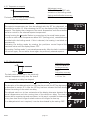
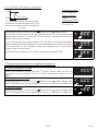
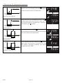
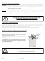
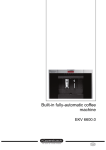
Operating Instructions
Waterbaths
WNB 7 - 45
1 General notes and safety notes............................................................................................................ 3
1.1 Transport ................................................................................................................................. 3
2 Technical data ..................................................................................................................................... 4
2.1 Material quality ....................................................................................................................... 5
2.2 Electrical equipment ................................................................................................................ 5
2.3 Note on EMC (electromagnetic compatibility)........................................................................... 5
2.4 Brief technical description ........................................................................................................ 5
2.5 Standard equipment ................................................................................................................ 6
3 Installation .......................................................................................................................................... 6
3.1 Initial start-up .......................................................................................................................... 7
3.2 Start-up - waterbath ................................................................................................................ 7
4 Bath construction and operation ......................................................................................................... 8
4.1 Controls and indications .......................................................................................................... 8
4.2 Switching on ........................................................................................................................... 9
4.3 Setting the parameters ............................................................................................................ 9
4.3.1 Temperature setpoint .......................................................................................................... 10
4.3.2 Delayed switch-on .............................................................................................................. 10
4.3.3 Hold time of the setpoint temperature ................................................................................ 11
5 Programming example of a programme sequence ............................................................................. 11
6 Monitoring the programme sequence ............................................................................................... 12
7 Temperature monitor and protection devices ..................................................................................... 13
7.1 Mechanical temperature monitor: temperature limiter............................................................ 13
7.2 Low-level protection .............................................................................................................. 13
7.3 Monitor relay ......................................................................................................................... 13
8 Use of the cover (special equipment) ................................................................................................. 14
9 Level control (special equipment)....................................................................................................... 14
10 Cooling system (special equipment) ................................................................................................. 15
11 Cleaning and maintenance .............................................................................................................. 15
12 Check list for fault rectification ........................................................................................................ 16
13 Action on supply failure .................................................................................................................. 16
14 Glossary .......................................................................................................................................... 16
15 CE Conformity of Declaration .......................................................................................................... 17
16 Address and customer service.......................................................................................................... 18
17 Index .............................................................................................................................................. 19
BASIC
page 2
1 General notes and safety notes
You have purchased a technically fully proven product which has been produced in Germany with the use
of high-grade materials and the application of the latest manufacturing techniques; it has been factory
tested for many hours.
For this waterbath we guarantee spare parts to be available up to 10 years.
Observation of the Operating Instructions is necessary for faultless
operation and for any possible claims under warranty. If these
Instructions are disregarded, all claims under warranty, guarantee
and indemnification are excluded!
This mark on the product means:
Note Operating Instructions
Warning – bath hot when operating
The right to technical modifications is reserved.
Dimensional details are not binding.
1.1 Transport
Always use gloves!
If the units WNB 22 to 45 have to be carried, 2 persons are required.
Place the bath accurately horizontal and
not on an inflammable support!
page 3
BASIC
2 Technical data
Model
Volume [liter]
Usable bath length A [mm]
Usable bath width B [mm]
Usable bath depth C [mm]
Housing length D [mm]
Housing width E [mm]
Housing height (with flat cover) F [mm]
Housing height (with gable cover) G [mm]
Weight [kg]
Current consume [A]
Power [W]
Ambient conditions
Setting temperature range
Setting accuracy
Indication accuracy
Working temperature range
BASIC
7
10
14
22
29
45
7
10
14
22
29
45
240
350
350
350
590
590
210
210
290
290
350
350
140
140
140
220
140
220
468
578
578
578
818
818
356
356
436
436
516
516
238
238
238
296
238
296
337
337
347
405
343
401
11
14
16
17
24
26
5,2
5,2
7,8
8,7
10,4
12,2
1200
1200
1800
2000
2400
2800
Ambient temperature 5ºC - 40°C
rh max. 80% (no condensation)
Overvoltage Category: II
Contamination degree: 2
10°C to 95°C
with activation of the boiling mode up to 100°C, see
section 4.3.1
0,1°C
0,1°C
5ºC above ambient temperature to nominal temperature
= maximum temperature (see rating plate)
page 4
2.1 Material quality
Memmert is using stainless steel (Mat.Ref. 1.4301) for the external casing as well as for the interior, an
outstanding material because of its high stability, optimum hygienic features and corrosion resistance
against many (not all!) chemical combinations (Attention e.g. at chlorine combinations!).
The load has to be tested for its chemical compatibility with the materials mentioned above.
A material-compatibility table covering all these materials can be requested from MEMMERT.
WARNING! Always pull out the supply plug before
opening the bath cover!
2.2 Electrical equipment
•
•
•
•
•
•
•
Operating voltage see rating label, 50/60 Hz
Protection Class 1, i.e. operating isolation with ground connection to EN 61 010
Protection IP20 to DIN EN 60 529
Interference suppression to EN55011 Class B
Bath protected by a fuse 250V/15A fast blow
Controller protected by a 80 mA fuse (200 mA on 115 V)
When connecting a MEMMERT bath to the electrical supply you have to observe any local
regulations which apply (e.g. in Germany DIN VDE 0100 with FI protection circuit)
2.3 Note on EMC (electromagnetic compatibility)
This product is intended to operate on a supply network with a system impedance Zmax at the transfer point
(building connection) of 0.292 Ohm max. The user has to ensure that the product is only operated on an
electrical supply network which meets these requirements. If necessary, details of the system impedance
can be obtained from the local electricity supply authority.
Note:
Any work which involves opening up the bath must only be
carried out by a properly qualified electrician!
2.4 Brief technical description
MEMMERT-waterbaths are electrically heated and electronically controlled.
The temperature of the thermostating liquid is continuously controlled by a microprocessor-controller
with pulse package control. Electronic microprocessor-PID-controller with continuous power matching
and autodiagnostic system with fault indicator (see section 12), integral timer for digital programme time
selection.
The temperature is measured using a Pt 100 temperature sensor (4-wire circuit). The accuracy is as
follows:
WNB
0,1ºC
±0,1ºC
Setting accuracy
Temperature fluctuation
The components of temperature control are controlled by integrated malfunction-recognition. The heaters
are installed outside - therefore no problems through dirt or limeresidue.
page 5
BASIC
2.5 Standard equipment
•
Electronic fuzzy-supported PID process controller with delayed programme start and programmable
hold time. The controller has permanent power matchinig and an autodiagnostic system for rapid
fault finding
•
Recessing push/turn control for simple operation of bath
•
Visual alarm indication
•
Mechanical temperature limiter (TB Class 1)
•
Monitor relay to switch off heating in case of fault
•
High-grade stainless-steel Pt100-temperature sensor (Mat.Ref. 1.4571) Class A in 4-wire circuit
•
Boiling mode for temperatures above 95°C
Special equipment (to be ordered separately as accessory): flat cover with concentric ring sets, gable cover
to drain condensate, cooling device, various racks for test tubes, bottles etc
3 Installation
min.
750mm
space for
air circulation
min.
80mm
space for
air circulation
min.
80mm
The unit must be placed on a horizontal, non-flammable surface which cannot tilt.
The vent openings in the left and back side must remain unobstructed. Minimum wall spacing on all sides
is 80 mm. The minimum spacing from the top of the bath to the next ceiling (rack, etc.) is 750 mm.
BASIC
page 6
3.1 Initial start-up
When the bath is started up for the first time, it should be supervised continuously until steady conditions
have been reached.
3.2 Start-up - waterbath
Mains
connection
The mains connection cable must be placed away from any hot surface.
Filling
max water level
min water level
drain valve
In order to garant the high quality of the stainless steel it is recommended by the
steel producer to fill the waterbath with deionised water.
IMPORTANT! The bath has to be filled up to a level between the
two markings at the right side of the tub!
Waterbaths can be fitted with a
level control system (see section 9).
Draining
The tank can be drained through the drain valve. The thermostating fluid must be cooled
to room temperature before draining. Drain the fluid either directly into an appropriate
container or connect an appropriate hose to the drain valve.
NOTE: Polluted fluids may not be drained directly into the public
wastewater system! If the thermostating fluid is polluted, please
make sure that it will be properly filtered or dumped according to
the applicable regulations!
Operation with non-flammable thermostating liquids only!
page 7
BASIC
4 Bath construction and operation
relatively largest heat loss (since
furthest away from the heated ribs)
minimum heat loss (since
very close to the heated ribs)
bath
Insulation
heating elements
The heating positioned on three sides around the tank ensures a natural water circulation of the liquid
inside, thus securing an optimal uniform temperature distribution.
4.1 Controls and indications
time-symbol
delay-symbol
(delayed switch-on)
temperature display
7 5. 0
hold-symbol
(hold time)
alarm-symbol
SET key
BASIC
heater-symbol
push/turn control
page 8
4.2 Switching on
The bath is switched on by pressing the push/turn control
and can be operated in connection with the
SET-key.
Bath switched off: The push/turn control is
pushed in and protected against damage.
4.3 Setting the parameters
A parameter can be selected by rotating the push/turn control; all other parameters are then dimmed.
The selected parameter flashes brightly and can now be altered with the push/turn control while holding
down the SET key (protection against unintentional alteration).
If the push/turn control is rotated quickly the setpoint is altered in large steps; with slow operation it is
altered in single steps.
After the SET key has been released the newly set value is stored.
Further rotation of the push/turn control selects the next parameter.
Rotation of the push/turn control selects the following parameters (in the order indicated), to be altered
as described above:
1.
2.
3.
Temperature setpoint
Delayed switch-on
Hold time of the setpoint temperature
page 9
BASIC
4.3.1 Temperature setpoint
Adjustment range:
10°C to 95°C or ca. 100°C with
activation of the boiling mode
*
90°C
Setting and indication accuracy:
0,1°C
The bath starts to heat up immediately
to the set temperature.
Rotate the push/turn control until the
°C
symbol flashes.
The setpoint temperature can then be selected with the SET key depressed, as
described in section 4.3. After releasing the SET key the display briefly flashes the
setpoint. The display then changes to the actual temperature and the controller
starts to control to the selected setpoint temperature.
During heating the
°C
symbol flashes in proportion to the actual heater power.
In order to reach water temperatures above 95°C (boiling point), waterbaths are
provided with the boiling mode. If this is selected, the heating is switched on
permanently.
Activating the boiling mode by rotating the push/turn control beyond the
maximum value until the display shows “CCC“
°C
The setting “boiling mode“ is not stored permanently. After the bath is switched
off and on again, the controller shows again the previously selected setpoint.
4.3.2 Delayed switch-on
Adjustment range:
1 min bis 99.59 hrs
*
90°C
Setting accuracy:
1 min
delay 12h
Indication accuracy:
<10 hrs: 1 min
≥10 hrs: 1 hr
The bath starts to heat up to the previously
selected temperature only after the time of
the switch-on delay has elapsed.
Rotate the push/turn control until the
(delay) and the
symbol flashes.
The duration of the delayed switch-on can then be set with the SET key depressed
as described in section 4.3. After the SET key has been released the bath briefly
flashes the setting of the switch-on delay.
The delayed switch-on is then activated and the display alternates between the
actual temperature and the running time of the switch-on delay. The time is
shown with a negative sign and runs down. In this way it is possible to determine
at any time how much longer the bath waits until it begins to heat up.
If no delayed switch-on is required, it can be de-activated by the setting “OFF“.
BASIC
page 10
°C
°C
°C
4.3.3 Hold time of the setpoint temperature
Adjustment range:
1 min bis 99.59 hrs
*
90°C
hold 6h
Setting accuracy:
1 min
t
Indication accuracy:
<10 hrs: 1 min
≥10 hrs: 1 hr
The bath switches off the heating after
the end of the selected hold time. In this
case the hold time includes the heatingup time.
Rotate the push/turn control until the
(hold) and the
symbol flashes.
The duration of the hold time can then be selected with the SET key depressed,
as described in section 4.3. After the SET key has been released the bath briefly
flashes the hold time setting.
If no hold time has been programmed, the hold time is activated immediately
and the display alternates between the actual temperature and the running time
of the hold time. As with switch-on delay, the residual time is shown with a
negative sign and runs down.
If no hold time is required, it can be de-activated by the setting “OFF“
°C
°C
°C
5 Programming example of a programme sequence
1. Setpoint temperature setting
Rotate the push/turn control until the °C symbol flashes. With the SET key
depressed, use the push/turn control to set the temperature setpoint to f.ex.
90.0 °C.
2. Delayed switch-on setting
°C
Rotate the push/turn control until the
(delay) and the symbol flashes. With
the SET key depressed, use the push/turn control to set the time f.ex. 6.00 hours.
°C
3. Hold time setting
Rotate the push/turn control until the
(hold) and the symbol flashes. With
the SET key depressed, use the push/turn control to set the time f.ex. 4.00 hours.
page 11
°C
BASIC
6 Monitoring the programme sequence
symbol
During the delayed switch-on the
flashes and the display alternates between
residual time and actual temperature
*
90°C
delay 6h
hold 4h
t
°C
Bath does not heat up
*
90°C
delay 6h
hold 4h
°C
After the end of the delayed switch-on the
symbol goes dark and the bath heats up to
the selected setpoint temperature. Heating is
indicated by the symbol.
°C
symbol flashes
During the hold time the
and the display alternates between the residual
time and the actual temperature.
°C
t
Bath heats up
*
90°C
delay 6h
hold 4h
t
°C
Bath holds setpoint
temperature
After the hold time has elapsed the
symbol
goes dark, the heating is switched off, and
the display alternates between the actual
temperature and “end“.
*
90°C
delay 6h
hold 4h
t
°C
Heating is switched off
BASIC
°C
page 12
7 Temperature monitor and protection devices
7.1 Mechanical temperature monitor: temperature limiter
All waterbaths are fitted with a mechanical temperature limiter (TB) Protection Class 1 to DIN 12880.
If the electronic control unit should fail during operation and the fixed factory-set maximum temperature is
exceeded by approx. 30°C the temperature limiter switches off the heating permanently as a final protective
measure. The symbol lights up continuously as warning.
7.2 Low-level protection
In addition to its function as overtemperature protection the TB also operates as low-level protection,
i.e. the heating is switched off permanently if the liquid drops below a certain level. As a warning the
symbol lights up continuously.
Fault rectification after the TB cut-out has been activated:
1.
Switch off the bath and allow it to cool down
2.
Rectify the fault (e.g. top up the liquid, replace temperature probe) and where appropriate contact
customer service
3.
The bath is again ready for operation only after it has cooled down and after the fault has been
rectified
7.3 Monitor relay
In addition the bath is equipped with an electronic monitor relay.
If a fault occurs during operation or if the selected setpoint temperature is exceeded by 10°C, then the
monitor relay continues control of the heating at this temperature in emergency operation.
The symbol flashes as warning.
Fault rectification after the monitor relay may been activated:
Check the controller for error messages (see section 12) and where appropriate contact customer service.
Example:
With a setpoint temperature of 80°C, if a fault occurs in the power unit (faulty triac) the bath continues to
operate in emergency operation at approx. 90°C.
page 13
BASIC
8 Use of the cover (special equipment)
Gable cover
The gable cover (may be ordered as already mounted special equipment) should always
be closed in order to prevent evaporation of thermostating liquid and to obtain optimal
temperature distribution. The gable shape of the cover makes sure that condensed water
will not drop down into the loads.
Flat cover
For positioning of test flasks on top of the bath, a flat cover (special equipment) may be
used. The size of the holes in this cover can be adapted to the flasks with ring inserts. The
rings may therefore only be inserted or taken off, if the bath is cooled down.
Note that during operation the flat cover and the gable cover
heat up to the temperature of the thermofluid!
9 Level control (special equipment)
2 different filling levels can be maintained constant if the unit is fitted with a level control system. When
using water as thermostating liquid, connect the feed pipe with tubing to the mains water supply. The
drain must be connected with tubing to an appropriate container or sink.
Make sure, that the tubing cannot be clogged or bended, and that it continually runs downhill.
Please note, that the outflowing water may be hot!
Supply and drain are indentified by arrows. Use temperature
resistant material for the tubing.
If the second overflow is not required, it must be closed with
a sealing cap.
The evaporation loss can be compensated through a slightly
open water supply (dripping) and can be monitored through
the “observation window“.
The level control system cannot be retrofitted!
Warning – bath hot when operating
BASIC
page 14
observation
window
supply
drain
drain
10 Cooling system (special equipment)
If the waterbath is fitted with a cooling device
for quicker cooling of the bath liquid, the “water
supply“ has to be connected by a hose f.ex. to a
cold water supply line. The “discharge“ has to
be lead into a drain.
water supply
(Use temperature resistant material for the
tubing)
discharge
Please note, that the outflowing water may be hot!
The discharge must be connected with tubing to an appropriate container or sink. Make sure, that the
tubing cannot be clogged or bended, and that it continually runs downhill.
11 Cleaning and maintenance
By regular cleaning of the easy to clean the tank, residues are
avoided which at continuous influence can impair the outfit and
function of the waterbath.
Please use only detergents and antiliming agents appropriate for
stainless steel for the cleaning of the tank and the housing (stainless
steel detergents usual in the trade)!
After cleaning and after draining the water the
stainless steel tank must be rinsed thoroughly with clear water
and dried carefully!
It is important to ensure that no rusting objects come into contact with the stainless steel bath tank or the
stainless steel housing. Rust sediments lead to contamination.
If rust stains caused by contamination occur on the tank surface, the affected areas must be cleaned and
polished immediately.
On units with gable cover we recommend that the hinge bolts are oiled from time to time if the bath is
used frequently.
page 15
BASIC
12 Check list for fault rectification
Main switch ON,
no indication on the display
symbol not alight
symbol alight
symbol flashes
CONF
E-1
E-2
E-3
E-L
Main fuse 15A or instrument fuse T80mA 250V~ on circuit board
55167.x has blown
Controller faulty
Electrical supply interrupted
Ambient temperature too high
Temperature in bath above the selected setpoint temperaturer
Temperature protection (TB) has operated
Liquid level too low
Monitoring relay has operated
Error on self test
Power module triac faulty
Power module faulty
Pt100-temperature probe faulty
Communication to power unit interrupted
In case of a malfunction contact an authorized service station for Memmert equipment or please inform
the Memmert service department (see section 16).
In case of queries always specify model and serial number (on the rating label).
13 Action on supply failure
After a failure of the supply, operation continues with the previously set parameters.
14 Glossary
•
nominal temperature = themaximum adjustable setpoint temperature of the bath.
•
ambient temperature = the continuous temperature of the room in which the bath is set up.
BASIC
page 16
15 CE Conformity of Declaration
EC Declaration of Conformity
Manufacturer´s name and address:
MEMMERT GmbH + Co. KG
Äußere Rittersbacher Straße 38
D-91126 Schwabach
Waterbath
WNB...
7 / 10 / 14 / 22 / 29 / 45
AC 230 V 50/60 Hz
alternative AC 115 V 50/60 Hz
Product:
Type:
Sizes:
Nominal voltage:
The designated product is in conformity with the European EMC-Directive
2004/108/EEC
including amendments
Council Directive of 03 May 1989 on the approximation of the laws of the Member States relating to
electromagnetic compatibility.
Full compliance with the standards listed below proves the conformity of the designated product with the essential
protection requirements of the above-mentioned EC Directive:
DIN EN 61326:2004-05
EN 61326:1997
EN 61326/A1:1998
EN 61326/A2:2001
EN 61326/A2:2003
The designated product is in conformity with the European Low Voltage Directive
2006/95/EEC
including amendments
Council Directive on the approximation of the laws of the Member States relating to Electrical
equipment for use within certain voltage limits.
Full compliance with the standards listed below proves the conformity of the designated product with the essential
protection requirements of the above-mentioned EC Directive:
DIN EN 61 010-1 (VDE 0411 part 1):2002-08
DIN EN 61 010-2-010 (VDE 0411 part 2-010):2004-06
EN 61 010-1:2001
EN 61 010-2-010:2003
Schwabach, 03.07.08
______________________________
(Legally binding signature of the issuer)
This declaration certifies compliance with the above mentioned directives but does not include a property assurance. The
safety note given in the product documentation which are part of the supply, must be observed.
page 17
BASIC
Standard units are safety-approved and bear the test marks:
This product is subject to the Directive 2002/96/EC by the European Parliament
and the EU Council of Ministers which concerns Waste Electrical and Electronic
Equipment (WEEE). This product has been put on the market after 13 August
2005 in countries which have already incorporated this Directive into National
Law. It should not be disposed off as part of domestic refuse. For disposal
please contact your dealer or the manufacturer. Products which are infected,
infectious or contaminated with health-endangering substances are excluded
from return. Please note also all further regulations in this context.
16 Address and customer service
MEMMERT GmbH+Co.KG
PO Box 17 20
91107 Schwabach
Germany
Phone: 00 49 9122 / 925-0
Fax:: 00 49 9122 /14585
E-mail: [email protected]
Internet: www.memmert.com
Customer service:
Phone: 00 49 9122 / 925-143
or 00 49 9122 / 925-126
E-mail: [email protected]
In case of queries always specify model and serial number (on the rating label).
© by MEMMERT GmbH+Co.KG
BASIC
page 18
17 Index
A
H
T
address 18
alarm symbol 13
ambient conditions 4
ambient temperature 16
autodiagnostic system 5, 16
heating 8
hinge bolts 15
hold time of the setpoint temperature 11
B
indications 8
initial start-up 7
installation 6
TB 13
technical data 4
temperature fluctuation 5
temperature limiter (TB) 13
temperature measurement 5
temperature monitor 13
thermofluid 7
transport 3
L
U
level control system 7, 14
liquid level 7
low-level protection 13
uniform temperature distribution 8
bath construction 8
boiling mode 4
boiling mode, activate 10
brief technical description 5
C
CCC 10
CE conformity of declaration 17
check list for fault rectification 16
chemical compatibility 5
cleaning 15
contaminations 7, 15
controls 8
cooling system 15
cover, flat 14
cover, gable 14
customer service 18
D
deionised water 7
delayed switch-on 10
DIN 12880 13
disposal 18
draining 7
drain hose 14, 15
drain valve 7
E
electrical equipment 5
electromagnetic compatibility 5
evaporation loss 14
F
fault rectification 16
filling 7
G
I
W
water circulation 8
working temperature range 4
M
maintenance 15
Mat.Ref. 1.4301 5
material quality 5
monitoring the programme sequence 12
monitor relay 13
monitor unit 13
N
nominal temperature 4, 16
P
parameter settings 9
polluted fluids 7
programming example 11
Protection Class 1 13
Pt 100 temperature sensor 5
R
rust deposits 15
S
safety notes 3
setpoint temperature 16
setpoint temperature, selection 10
standard equipment 6
start-up 7
supply failure 16
switching on the bath 9
glossary 16
page 19
BASIC
Memmert GmbH + Co. KG | Po. Box 1720 | D-91107 Schwabach | Tel. +49 (0) 9122 / 925 - 0 | Fax +49 (0) 9122 / 145 85 | E-Mail: [email protected] | www.memmert.com
08.06.2009
Waterbath BASIC englisch
D10329