1
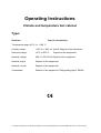
Operating Instructions
Climate and temperature test cabinet
Type:
Serial no.:
Year of construction:
Temperature range:-40°C to +180 °C
Humidity range:
+10% to + 98% rel. humid. Depend of the equipment
Dew point range:
+5°C to 89.5°C
Nominal voltage:
400 V 3/ PE 50 Hz Depend of the equipment
Nominal output:
Depend of the equipment
Nominal current:
Depend of the equipment
Compressor:
Depend of the equipment Refrigerating agent: R404A
Depend of the equipment
C:\Program Files\Apache Group\Apache2\htdocs\cdsconv\results\988156977\CT40-500UserManual.doc/31.01.2005 2:52 /Rg
Directory
DIRECTORY ............................................................................................................................2
1. GENERAL INFORMATION..................................................................................................4
1.1
Handling of the operating instructions .....................................................................4
2. SAFETY REGULATIONS AND EQUIPMENTS...................................................................5
2.1
Safety regulations .......................................................................................................5
2.2
Safety remarks.............................................................................................................6
2.2.1
Signal words...........................................................................................................6
2.2.2
Warranty and liability ..............................................................................................6
2.2.3
Application in accordance with the purpose / Misuse.............................................7
2.2.4
Limits of the machine .............................................................................................7
2.2.5
Warning against remaining dangers.......................................................................8
2.3
Safety devices / Protection caps................................................................................8
2.4
Behaviour in Case of Emergency in relation with refrigerating agents .................9
3. STARTING-UP: PREPARATION AND EXECUTION........................................................10
3.1
Requirements for the place of installation..............................................................10
3.2
Installation and preparation of the test cabinet......................................................10
3.3
Starting-up .................................................................................................................14
3.4
Closing down .............................................................................................................15
3.5
Shutdown, disposal...................................................................................................15
4. CTS-CHAMBER.................................................................................................................16
4.1
Position of accessories and connections + dimensions.......................................16
4.2.
Technical performance characteristics...................................................................17
4.3
Description of the installation ..................................................................................17
5. CONTROL UNIT OF THE INSTALLATION.......................................................................18
5.1
Control in general......................................................................................................18
C:\Program Files\Apache Group\Apache2\htdocs\cdsconv\results\988156977\CT40-500UserManual.doc/31.01.2005 2:52 /Rg
5.2
Specimen protection device (option) ......................................................................18
5.3
Digital outputs (option) .............................................................................................18
5.4
Digital inputs (option) ...............................................................................................18
5.5
Interface ports............................................................................................................19
6. OPERATION WITH CTS OPERATING UNIT ....................................................................20
6.1
Manual Mode..............................................................................................................21
6.2
Automatic Mode.........................................................................................................24
6.3
Software - Temperature limiter.................................................................................27
6.4
Interface configuration..............................................................................................28
6.5
Automatic Editor........................................................................................................30
6.6
Special menus ...........................................................................................................37
6.6.1
Display of power outage times .............................................................................37
6.7
Interface protocol CTS control <--> PC ...................................................................38
7. POSSIBLE MALFUNCTIONS OF THE INSTALLATION ..................................................43
8. MAINTENANCE.................................................................................................................45
9. INDEX ................................................................................................................................47
C:\Program Files\Apache Group\Apache2\htdocs\cdsconv\results\988156977\CT40-500UserManual.doc/31.01.2005 2:52 /Rg
1. General Information
1.1
Handling of the operating instructions
These operating instructions are to be permanently available on the installation.
These operating instructions are to be read and applied by any person working
on/with the installation, i.e.
− operating, including equipping, care or trouble-shooting
− service and maintenance
− transport
These operating instructions aim at facilitating the knowledge about the machine and
the machine handling.
These operating instructions include important remarks for a secure, correct and
economic installation operation. They contribute to avoid dangers, to prevent repair
costs and to reduce the failure times as well as to increase the reliability and the serviceable life of the installation.
These operating instructions contain instructions and information concerning the CTS
range of climate test cabinets type C.
They describe the assembly, starting-up and function of the installation.
They also include details in the case of failures and for maintenance works.
The abbreviation CTS is used in these operating instructions as a company designation for Clima-Temperatur-Systeme.
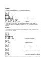
The type designation of the CTS range of cabinets consists of
i.e. Type C –40/600
1) C
2) -40
3) 600
means:
means:
means:
Climate
low temperature -40°C
600 litres test space volume
We reserve the right to make technical modifications, compared with representations
and information given in these operating instructions, aiming at an improvement of
the installation, as long as they are not in contradiction with security aspects,.
C:\Program Files\Apache Group\Apache2\htdocs\cdsconv\results\988156977\CT40-500UserManual.doc/31.01.2005 2:52 /Rg
2. Safety regulations and equipments
2.1
Safety regulations
All regulations as listed below have been observed for the design and the manufacture of the installation.
2.1.1 EC Directives and National Legislation
-
EC Directive for machines 98/37/EC
EC Directive on Low Voltage 73/23/EEC in the version 93/68/EEC
Directive on EMC 89/336/EEC in the versions 92/31/EEC and 93/68/EEC
Device safety law in the version of 28-09-95
Directive for pressure devices 97/23 EC
2.1.2 Mechanical Norms
-
EN 292-1,2 (issue T1 11/1991 ; T2 06/1995)
EN 294 (issue 08/1992)
EN 378-1,2,3,4 (issue 06/2000)
EN 563 (issue 01/2000)
EN 61310-1,2 (issue 09/1996)
DIN 8901 (issue 12/1995)
2.1.3. Electrical Norms
-
EN 50081 (issue 03/1994)
EN 61000-6-2 (issue 12/2001)
EN 61010-1 (issue 03/1994)
DIN 12880 (issue 11/1978)
DIN VDE 0100-410 (issue 01/1997)
BGV A2 (issue 1998)
C:\Program Files\Apache Group\Apache2\htdocs\cdsconv\results\988156977\CT40-500UserManual.doc/31.01.2005 2:52 /Rg
2.2
Safety remarks
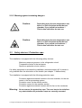
2.2.1 Signal words
The following signal words (acc. to ANSI Z535.4) are used in these operating instructions
DANGER
means an immediate threatening danger. If nothing is done to avoid
it, death or very severe injuries will follow.
WARNING
means a possibly dangerous situation. If nothing is done to avoid it,
death or very severe injuries may follow.
CAUTION
means a possibly dangerous situation. If nothing is done to avoid it,
light injuries may follow.
ATTENTION means a possibly damaging situation. If nothing is done to avoid it,
the product or something in its environment may be damaged.
REMARK
indicates application recommendations and other particularly useful
situations
2.2.2 Warranty and liability
Attention:
It is absolutely necessary to read these operating instructions
before starting-up the installation in order to prevent damages
and failures due to wrong handling.
The operation of the installation as well as its maintenance must
be performed by instructed and authorised personnel.
We decline any responsibility and any warranty in the case of
handling malpractice against these operating instructions.
The installation has been checked before its delivery with respect to its perfect function and safety.
Any modification of the installation requires the agreement of CTS.
C:\Program Files\Apache Group\Apache2\htdocs\cdsconv\results\988156977\CT40-500UserManual.doc/31.01.2005 2:52 /Rg
2.2.3 Application in accordance with the purpose / Misuse
The installation is designed, constructed and manufactured for the sole application
consisting in trials for temperature and climate tests.
The installation cannot be used for tests on explosive, corrosive, toxic or easy inflammable materials nor with specimens generating or releasing such materials.
Danger :
No living being is allowed to stay in the test chamber. There is
danger to life.
Danger :
The preparation of any food with the installation is prohibited.
The observance of the operating instructions and of the maintenance prerequisites as
described in chapter 8, belong to the scope of applications in accordance with the
purpose.
The installation is to be used only in a technically perfect condition, as well as in accordance with its purpose, under observance of safety rules and dangers, and following these operating instructions.
Malfunctions must be eliminated immediately.
The installation is built according to the to-date technical knowledge and recognised
safety-related rules. Its application can however cause risks to the life of the user or
to the life of third persons or prejudices to the installation or to other material property.
Warning: The owner must compile operating instructions for the operators
of this installation regarding the security measures with regard to
the handling of a refrigerating installation resp. with the applied refrigerating agents.
2.2.4 Limits of the machine
Refer to the drawing of the devices (see chapter 4.1) for the limits of the machine.
The operation takes place from the door side.
C:\Program Files\Apache Group\Apache2\htdocs\cdsconv\results\988156977\CT40-500UserManual.doc/31.01.2005 2:52 /Rg
2.2.5 Warning against remaining dangers
2.3
Caution:
Depending upon the test temperature set,
there is a risk of injuries inside the test
chamber, if you touch hot surfaces !
This is also valid after the test run.
Caution:
Depending upon the test temperature set,
there is a risk of injuries inside the test
chamber, if you touch cold surfaces !
This is also valid after the test run.
Safety devices / Protection caps
The installation is equipped with the following safety devices:
Maximum pressure governor in the refrigeration circuit
Temperature limiter in the test space
Specimen protection device (option)
If a safety equipment is actuated the installation remains switched off. A restart is
only possible after the elimination of the trouble (see chapter 7: Malfunctions)
The installation is equipped with the following protection caps:
Protection against accidental contact in the test chamber, for the elements in the air processing system.
Protection cover for the electric section
Protection covers for the machine section
Protection against accidental contact with the fan on the condenser.
Warning: Never remove the protection caps. The user has to check before
any start whether all protection caps are correctly mounted.
C:\Program Files\Apache Group\Apache2\htdocs\cdsconv\results\988156977\CT40-500UserManual.doc/31.01.2005 2:52 /Rg
2.4 Behaviour in Case of Emergency in relation with refrigerating
agents
The safety data sheets for the applied refrigerating agents are to be observed!
Refer to the safety data sheets for the respectively necessary personal protection equipment.
CAUTION :
If missing of refrigerants, the chamber has to be switched off
and service of CTS has to be called. The security remarks in
the safety data sheets in appendix has to be observed.
C:\Program Files\Apache Group\Apache2\htdocs\cdsconv\results\988156977\CT40-500UserManual.doc / 31.01.2005 2:52
/ Rg
9
3. Starting-up: Preparation and Execution
3.1 Requirements for the place of installation
Attention: CTS uses refrigerants of the group ‘L1’ according to EN 378-1
part 5.4 .
Installation of refrigerating is designed according to EN 378-1 for
class B of the installation ranges.
According appendix ‘C’ of EN 378-1 there are no limits regarding
the quantity of the refrigerants filling, if the chamber will be installed at ground floor or at underground/upper floor with enough
emergency exits.
Otherwise for quantity of refrigerant filling following dimensioning value will be responsible for :
R404A Æ 0,48 kg/m³ (m³ - volume of installation room)
R 23 Æ 0,68 kg/m³
Please take the quantity of refrigerant from thetype plate of the
chamber, the curcuit with max. refrigerant filling will be considerable.
The owner or the operator must take into account this conditions!
The admissible ambient temperature lies between +15 and +30°C, and the admissible ambient humidity between 20 and 75 % rel. humidity. The place must be well ventilated and dry. The floor must be plane.
Refer to the equipment drawing for the floor space required.
3.2
Installation and preparation of the test cabinet
Attention:
Transport the test cabinet only with the supplied pallet! Refer to
the technical specifications, chapter 4.2 for the weight.
Install the test cabinet as follows:
1.
Unpack the test cabinet and check the extent of supply.
2.
Remove the accessories from the test space or from the supplied boxes.
3.
Adjust the test cabinet on the workshop floor using a spirit level and turning
the adjustable footing.
Attention:
4.
Never use the test cabinet without its adjustable footing or rollers!
If equipped with rollers*, engage the roll stop device
C:\Program Files\Apache Group\Apache2\htdocs\cdsconv\results\988156977\CT40-500UserManual.doc / 31.01.2005 2:52
/ Rg
10
5.
Discharge from test cabinet and condensate into gully hole to be arranged
by the user.
6.
Connect cooling water supply* and runback pipes for the water-cooled version.
Refer to equipment drawing for the position of the supply connections.
Attention:
7.
Absolutely keep following cooling water parameters:
Supply temperature min.
: 12°C
Supply temperature max.
: 28°C
Water pressure
: 3 - 6 bar
Pressure lost
: min 1,5 bar
Water consumption at ∆tw=10K : approx. 0,6 m³/h
Customer's system to be bump-free.
Particle-free water with pH-value ab. 7
Filling up of the reservoir canister of the climatic system positioned behind the
front cover of the substructure.
Attention:
Repeatedly switching on the humidity system without water in
the reservoir canister leads to a destruction of the backfeeding
pump.(First acknowledge the error message E7 when water filling up has been done)
Attention:
Absolutely keep the following parameters for the moistening
water:
demineralized water with max. conductivity 10µS
pH-value 6 to 7
free of algae
Remark:
Test cabinets without automatic water backfeed device require areservoir refill just after the original filling of the climatic system! Regularly check the level!
8.
If the test cabinet is equipped with an automatic water backfeed device*, the
connection is made to the user's deionized water network.
Attention:
Keep following parameters for the deionized water network!
Supply temperature . max. 20°C
Pressure: 3 to 6 bar
No water hammers nor pressure variations within the system.
Attention: In the case of an automatic water backfeed, waste water run-off
must be free. A run-off hose connected by the user must bedirected into the gully hole without any superelevation. Minimum
hose size R 1/2“, maximum hose length 1.5m!
C:\Program Files\Apache Group\Apache2\htdocs\cdsconv\results\988156977\CT40-500UserManual.doc / 31.01.2005 2:52
/ Rg
11
Caution:
9.
Should you use a deionization device*, connect it to the installation with the set
of hoses belonging to the scope of supply. Connection at the bottom on the
reverse side of the installation.
The deionization device is connected by the user to an electric power supply
(230V , 50 Hz) and to a service water network (R 1/2“).
Caution:
Caution:
Attention:
Attention:
10.
Keep following water network parameters!
Supply temperature max. 20°C
Pressure: 3 to 6 bar
No water hammers nor pressure variations within the system
For the connection of the deionization device, observe by all
means the assembly and operating instructions from Seral, particularly the short instructions for beading gaskets and washers
into the Seralplus set of hoses SD.
It is necessary to bleed at least 20l water when setting a deionization cartridge into operation in order to achieve the admissible conductivity. Only after that, the cartridge can be connected
to the climatic test cabinet.
Controll the display of the deionization device weekly. Water
quality see chapter 3.2, topic 7.
Connect the compressed-air supply* to a compressed-air ductwork system
from the user.
Attention:
11.
The waste water can by very hot!
Observe following compressed air parameters!
Pressure: 6 to 10 bar overpressure
max. inlet temperature +35°C
quality classes acc. to ISO 8573-1 :
by direct discharge of the compressed air : particle, water and
oil content : class 3
by using an air dryer : particle and oil content : class 3; water
content : class 6
Close entry port with plugs.
Remark:
If you put in wires or pipes, the entry port must be closed with plastic
sealing (i.e. from Bostik). The sealing material must be appropriate
for the range of temperatures.
12.
Before connecting the electric power supply, check the tension, the frequency
and the mains fuse at the user's workshop and compare them with the indications on the nameplate. The nameplate is under the main switch.
13.
If the parameters are correct, connect the test cabinet to the electric power
C:\Program Files\Apache Group\Apache2\htdocs\cdsconv\results\988156977\CT40-500UserManual.doc / 31.01.2005 2:52
/ Rg
12
supply.
Attention:
Switch on the test cabinet only after it has reached the admissible ambient temperature of +15°C to +30°C!
*optional equipment
C:\Program Files\Apache Group\Apache2\htdocs\cdsconv\results\988156977\CT40-500UserManual.doc / 31.01.2005 2:52
/ Rg
13
3.3
Starting-up
1.
Place a suitable specimen into the test space
Attention
2.
3.
4.
5.
6.
7.
8.
Exothermal specimen in the switched-off installation would heat
the test space at unacceptably high values. The operator must
ensure that the heat loss from the specimen is interrupted when
the machine is stopped (even in the event of a malfunction). The
interruption can i.e. be performed with the potential-free interference contact.
(See connection diagram BG 00 page 1 for the connection)
Check whether all jobs described under 2.1 or whether due maintenance jobs
have been carried out
Turn main switch on “I“
Start further equipment, such as deionization installations or compressed-air
drier*, if available
Check the sense of rotation of the ventilator once the installation has started.
(see direction arrow on the ventilator motor).
Check the sense of rotation of the ventilator for the condenser once the installation has started (see direction arrow on the ventilator motor).
Place the sensor (Pt 100) of the specimen protection device* onto the
specimen and adjust the maximum temperature for the specimen on the
specimen protection device*.
Set the reversing cock* for moistening water in the required position.
Attention:
Attention:
Depending upon the climatic programme and the contaminant
emission from the specimen, it is necessary to drain the moistening water into the gully hole each 2nd to each 5th day. The
climatic system must furthermore be rinsed. For that purpose,
switch the climate operation on, wait 5 min., then switch the
climate off with the temperature control still running.
If the reversing cock brings back the moistening water into the
canister, refill only 2/3 of the canister because it would otherwise be filled to overflowing when the climatic system is
drained off.
The installation is now ready to work and can be operated with the corresponding
inputs on the control unit (see chapter 4) or through the interfaces RS232 or RS485.
*optional equipment
C:\Program Files\Apache Group\Apache2\htdocs\cdsconv\results\988156977\CT40-500UserManual.doc / 31.01.2005 2:52
/ Rg
14
3.4
Closing down
Before a longer standstill of the installation or in order to replace the water in the
bowl-type humidifer, it is necessary to set the moisture channel first on 0. Before actuating the main switch, the installation must still run about 5 minutes with active
temperature control.
Attention:
With a water-cooled condenser* of the refrigerating machine,
the water must be entirely removed from the cooling water circuit. If this is not done, damages can occur due to frost. It is appropriate to blow off the water with compressed air.
The following storage conditions are to be observed for longer immobilisation periods:
ambient temperature + 5°C to + 30 °C
dry, clean atmosphere
even floor surface
it is appropriate to cover the whole installation with a plastic sheet.
3.5
Shutdown, disposal
Contact CTS if an elimination is required after the shutdown of the installation.
The owner must in particular take care that the elimination of the operating mediums
(refrigerating agents, possibly heat transfer liquid and refrigerating machine oil) takes
place professionally and correctly and according to the respectively valid state of the
pertinent directives.
C:\Program Files\Apache Group\Apache2\htdocs\cdsconv\results\988156977\CT40-500UserManual.doc / 31.01.2005 2:52
/ Rg
15
4. CTS-Chamber
4.1
Position of accessories and connections + dimensions
This space is open
for the sketch of the
machine
C:\Program Files\Apache Group\Apache2\htdocs\cdsconv\results\988156977\CT40-500UserManual.doc / 31.01.2005 2:52
/ Rg
16
4.2. Technical performance characteristics
Temperature tests:
Temperature range
-40°C to +180°C
Temperature fluctuation
under stabilized conditions
±0.1 to ±0.3 K temporary
Depend of the equipment
4.3
Description of the installation
The function or the material property of a specimen under the influence of temperature and humidity can be tested using the temperature test cabinet.
The correct ventilation with an accordingly high quantity of circulating air is the warrant for a good transmission onto the specimen.
The air treatment space is on the back of the interior space.
The aggregates which are easily accessible from any side, are in the subconstructure
of the installation. The control unit is integratet in the construction on the rear side of
the cabinet.
The operating unit is user-friendly integrated in the door of the test space.
C:\Program Files\Apache Group\Apache2\htdocs\cdsconv\results\988156977\CT40-500UserManual.doc / 31.01.2005 2:52
/ Rg
17
5. Control unit of the installation
5.1
Control in general
The control unit is on the door, in the attached construction on the back side of the
installation.
Warning:
Only electricity specialists are allowed to open the electric box.
Before opening
1. Place main switch on “0“
2. Unplug mains plug
3. Protect the installation against restart
The main switch is on the right-hand side of the switch cabinet.
The switch for the test space lighting is on the right-hand front side. When you push it
the test space light run for maximum 12 minutes.
The plug-type connections for the potential-free contact, the digital and analog inputs
and outputs, as well as the interfaces, are on the side of the electric cabinet, on the
backside of the construction.
The cable entry takes place above the electric cabinet, through the leading-in rail.
5.2
Specimen protection device (option)
To protect the specimen against a too high temperature rise, a separate regulator is
mounted above the main switch. The specimen protection device has its own temperature probe (Pt 100) within the test chamber. This Pt 100 can be freely moved
and it can thus be fixed directly onto the specimen.
The upper display on the specimen protection device is the effective value of the free
probe on the specimen. The lower display is the limit value. The limit value is adjusted with the ⇑ and ⇓ keys. If the effective value exceeds the limit value the installation is switched off.
(See chapter 7 Malfunctions for re-starting the installation).
5.3
Digital outputs (option)
The digital outputs are potential-free contacts which can be used by the customer,
i.e. for triggering specimens or measuring devices.
Refer to the flow sheet BG 15 for the connection configuration.
Output triggering takes place via the operating panel or the interface (chapter 6).
5.4
Digital inputs (option)
The digital inputs are to be realised by the customer as potential-free contacts. The
digital inputs can be scanned via the interface or displayed or defined with the CTS
CID software.
Refer to the flow sheet BG 15 for the connection configuration.
C:\Program Files\Apache Group\Apache2\htdocs\cdsconv\results\988156977\CT40-500UserManual.doc / 31.01.2005 2:52
/ Rg
18
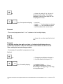
5.5
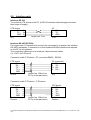
Interface ports
Interface RS 232
To connect a CTS device to the PC, a RS 232 interface cable belongs to the standard scope of supply.
CTS device
RX
TX
GND
PC
2 RX
3 TX
5 GND
2
3
5
SUB-D 9-channel
plug
length max. 15m
SUB-D 9-channel
socket
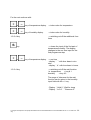
Interface RS 485 (OPTION)
For longer lines or if several devices are to be connected in a network, the interface
RS 485 is necessary. A converter or a fixed installed RS 485-interface are required
on the PC for this purpose.
The connection cables are to be made as 4 lead screened cables.
(i.e. LIYCY 4x 0.25 mm2)
Connection cable CTS device - PC (converter RS485 - RS232)
CTS device
RX +
RX TX TX +
GND
PC (converter)
2 TX +
9 TX 11 RX 4 RX +
1
2
3
4
5
5-channel-plug
Phoenix
length max. 500m from
PC up to the last device
SUB-D 15-channel
plug
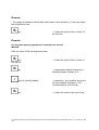
Connection cable CTS device - CTS device
CTS device
RX + 1
RX 2
TX 3
TX + 4
GND 5
5-channel-plug
Phoenix
length max. 500m from
PC up to the last device
CTS device
1 RX +
2 RX 3 TX 4 TX +
5 GND
5-channel-plug
Phoenix
C:\Program Files\Apache Group\Apache2\htdocs\cdsconv\results\988156977\CT40-500UserManual.doc / 31.01.2005 2:52
/ Rg
19
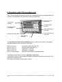
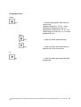
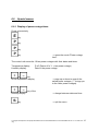
6. Operation with CTS operating unit
The CTS operating unit allows to operate the installation by hand meaning with fixed
values or automatically with previously written programmes.
Plus/minus keys
temperatur
Temperatur
edisplay
Plus/Minuskeys
humidity
Humidity display
(if available)
S-key (Start/Stop)
with LED
P-key (programme)
with LED
Function keys with LEDs
E-key (editor)
with LED
The operational mode of the installation can be read from the state of the green
luminous diodes in the P key and in the S key:
LED in P key on:
LED in P key off:
LED in S key on:
LED in S key off:
LED in S key flashes:
automatic mode (see topic 6.2)
manual mode (see topic 6.1)
installation is running
installation is stopped
operation interrupted in automatic mode
Temperature limits can be set as a specimen protection.
If the actual value in the test space exceeds or remains under the pre-set limits, the
installation is switched off.
(See topic 6.3 Software Temperature limiter)
C:\Program Files\Apache Group\Apache2\htdocs\cdsconv\results\988156977\CT40-500UserManual.doc / 31.01.2005 2:52
/ Rg
20
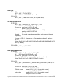
6.1
Manual Mode
In the manual mode, the set index values are regulated as constant values. The installation runs in the manual mode, if the LED in the P key is off.
Adjusting the temperature index value
key on temperature display
key on temperature display
→ higher index value
→ lower index value
Adjusting the humidity index value (if available)
key on humidity display
→ higher index value
key on humidity display
→ lower index value
Remark:
- To cut out the humidity, the humidity index value is given by "0".
- To restart the humidity, the humidity index value should be pre-set on a value within
the limits of the installation.
Starting the installation
key
→ starts the installation if it was
switched off (green LED in S key is
on)
Remark:
- the index values "F" and the actual values are displayed alternately, if the installation has started.
C:\Program Files\Apache Group\Apache2\htdocs\cdsconv\results\988156977\CT40-500UserManual.doc / 31.01.2005 2:52
/ Rg
21
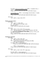
Stopping the installation
→ stops the installation if it was
switched on (green LED in S key is
off)
key
Additional functions
→ activates / deactivates the respectively assigned function.
(green LED in the respective key is on
/off)
1-2-3-4 key
Key assignment:
Key
1
Function
free
2
free
3
free
4
free
Description
C:\Program Files\Apache Group\Apache2\htdocs\cdsconv\results\988156977\CT40-500UserManual.doc / 31.01.2005 2:52
/ Rg
22
Malfunction indication
Temperature display
→ shows the temperature
Humidity display
→ “ E “ and error code number flash
(see topic 7 - Malfunctions on equipment)
Once the cause of the error has been eliminated, teh error can be acknowledge.
key
→ If the error has been eliminated, it
is acknowledged and the installation
restarts.
C:\Program Files\Apache Group\Apache2\htdocs\cdsconv\results\988156977\CT40-500UserManual.doc / 31.01.2005 2:52
/ Rg
23
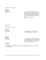
6.2
Automatic Mode
Switch the installation on STOP (green LED in
key is off)
Starting the installation in the automatic mode
→ opens the mode "Automatic"
key
or
key of temperature display
→ select programme number
Remark:
- The humidity display shows the actual time as xx.xx h.
If necessary, the starting time can be freely selected by actuating the
or
key of humidity display
→ select starting time xx.xx h.
If the installation should start only on the next day, the time can be set after 24.00 h.
key you
In this case, the temperature display shows the starting date. With the
take over the adjusted time. The programme starts then at the defined time.
(Display: LED in
key on, in
key off)
If the installation should start immediately, continue with:
key
→ starts the installation
(green LED in S key and in P key are
on)
C:\Program Files\Apache Group\Apache2\htdocs\cdsconv\results\988156977\CT40-500UserManual.doc / 31.01.2005 2:52
/ Rg
24
Programme interruption:
key
→ the installation interrupts the programme cycle. The index values and
the programme running times remain.
The ventilator and the temperature
control of the installation are switched
off.
(LED in S key flashes)
Then either
Programme continuation:
key
→ the programme cycle continues
(LED in S key and in P key on)
key
→ the programme cycle is finished.
For the following start, the cycle starts
from the beginning on. (green LED in
S key and in P key off)
or
Remark:
- If necessary, the programme number of the running programme can be asked for
by pressing the:
C:\Program Files\Apache Group\Apache2\htdocs\cdsconv\results\988156977\CT40-500UserManual.doc / 31.01.2005 2:52
/ Rg
25
key
→ “ P “ and the current programme
number are shown
→ the humidity display shows the remaining running time of the line.
→ in the 2nd step the current quantity
of the executed loops is shown “ LC“
Temperature display: passes of main
loop
humidity display: passes of present
loop (only for interlaced loops)
Remark:
In the case of a misoperation, stop the programme with the S key and repeat the operation with the desired programme number.
C:\Program Files\Apache Group\Apache2\htdocs\cdsconv\results\988156977\CT40-500UserManual.doc / 31.01.2005 2:52
/ Rg
26
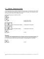
6.3
Software - Temperature limiter
The temperature limiter software allows to limit the range of temperature of the installation. If the effective temperature value is not within this range, the temperature control trips and the control unit indicates an error.
Press following keys one after the other:
key
→ opens the mode
“Temperature limiter“
key
or
key of temperature display
→ temperature limiter max.
or
key of humidity display
→ temperature limiter min.
key
→ save
Remark:
The control unit manages different limit values for manual and automatic modes. This
means that, if the temperature limits are modified during an automatic programme
run, these limits are only valid until the actually running programme is finished.
key
→ save
C:\Program Files\Apache Group\Apache2\htdocs\cdsconv\results\988156977\CT40-500UserManual.doc / 31.01.2005 2:52
/ Rg
27
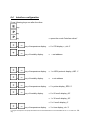
6.4
Interface configuration
Press following keys one after the other:
key
key
→ opens the mode "Interface driver"
key
or
key of temperature display
→ 0 = CID display = „cid. 0“
or
key of humidity display
→ = set address
or
key of temperature display
→ 1 = ASCII protocol display „ASC. 1“
or
key of humidity display
→
or
key of temperature display
→ 2 = printer display „EPS. 2“
or
key of humidity display
→ 0 = 60 mm/h display „60“
= set address
→ 1 = 30 mm/h display „30“
→ 2 = 6 mm/h display „6“
or
key of temperature display
→ 3 = time display „clo. 3“
C:\Program Files\Apache Group\Apache2\htdocs\cdsconv\results\988156977\CT40-500UserManual.doc / 31.01.2005 2:52
/ Rg
28
or
key of humidity display
→
or
key of temperature display
→ 4 = date day/month
display „ clo. 4“
or
key of humidity display
→
or
key of temperature display
→ 5 = date year display „ clo. 5“
or
key of humidity display
→ set year
or
key of temperature display
→ 6 , 7, ... further configuration, only
for service purposes.
key
= set time
set date
→ save the configuration
C:\Program Files\Apache Group\Apache2\htdocs\cdsconv\results\988156977\CT40-500UserManual.doc / 31.01.2005 2:52
/ Rg
29
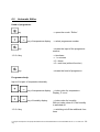
6.5
Automatic Editor
Head of programme:
→ opens the mode “ Editor “
key
or
key of temperature display
→ select programme number
→closes the input of the programme
number
key
1-2-3-4 key
→ time base
→ 1 = minutes
→2 = hours
→3 = real time (without function)
key
→closes the head of programme
Programme body:
Input of 1st pair of temperature/humidity
or
key of temperature display
→ index value for temperature
Display „P xxx.x“
or
key of humidity display
→ index value for humidity
With an index value of 0, the humidity
is switched off
1-2-3-4 key
→ switching on/off the additional functions
C:\Program Files\Apache Group\Apache2\htdocs\cdsconv\results\988156977\CT40-500UserManual.doc / 31.01.2005 2:52
/ Rg
30
→ closes the entry of the 1st pair of
temperature/humidity. The display
changes to the run time input for the
1st programme step
key
or
key of temperature display
→ run time
- display “ ´ “ for time base in minutes
- display “ h “ for time base in hours
- real time shows the current time
Remark:
- The current programme line " L xx" is shown in the humidity display
→ closes the run time input for the 1st
line
key
Remark:
A defined starting value with run time t = 0 minute should always be programmed as first line so that the automatic control does not take over the
value ending the last checking operation.
- If necessary it is possible to programme a loop.
Method:
→ Temperature displays changes to
„‘„ Humidity display changes to „L...“
key
or
key of humidity display
→ number of loops
(the display changes to “ SA xx “
according to the beginning of the loop,
xx loop passages)
C:\Program Files\Apache Group\Apache2\htdocs\cdsconv\results\988156977\CT40-500UserManual.doc / 31.01.2005 2:52
/ Rg
31
For the rest continue with:
or
key of temperature display
→ index value for temperature
or
key of humidity display
→ index value for humidity
→ switching on/off the additional functions
1-2-3-4 key
→ closes the input of the 2nd pair of
temperature/humidity. The display
changes to the run time input for the
2nd programme step
key
or
1-2-3-4 key
key of temperature display
→ run time
- display “ ´ “ with time base in minutes
- display “ h “ with time base in hours
→ switching on/off the wait function.
i.e. temperature
= key # 1
humidity
= key # 2
The range of tolerance for the wait
function can be given in the humidity
input field with the +/- key.
- Display “ Hold 0 “ Wait for temp
- Display “ Io 5.0 “ Tolerance 5°
C:\Program Files\Apache Group\Apache2\htdocs\cdsconv\results\988156977\CT40-500UserManual.doc / 31.01.2005 2:52
/ Rg
32
Remark:
- The range of tolerance defines with which index value deviation (+-) the next step in
the programme runs.
key
→ closes the input of the run time of t
the 2nd line
Remark:
If a loop has been programmed, it must also be closed.
Method:
After the input of the xth programme step
key
the xth line
key
key of humidity display
key
→ closes the input of the run time of
→ temperature display changes to „‘„
humidity display changes to „L ...“
→ press the + key to define the end of
the loop (display changes to “ SE “
corresponding to end of loop)
→ closes the input of the end of loop
C:\Program Files\Apache Group\Apache2\htdocs\cdsconv\results\988156977\CT40-500UserManual.doc / 31.01.2005 2:52
/ Rg
33
Programme end:
either:
→ sets the programme end onto the
current line
(display changes to “ PE xx “ corresponding to programme end, xx =
programme number and “ PL xx “ corresponding to current line, xx = current
programme line)
key
then:
key
→ quits the editor without saving
key
→ quits the editor and saves the programme up to the current line
or
or:
key
→ quits the editor and saves the total
programme
C:\Program Files\Apache Group\Apache2\htdocs\cdsconv\results\988156977\CT40-500UserManual.doc / 31.01.2005 2:52
/ Rg
34
Remark:
- Proceed as follows to visualize or to check the programme:
key
or
key,
→ select the programme
key
key,
key
→ passage
- In the case of a wrong input, quit the programme pressing 2 times the E key.
Restart the editing process and click on S key until your arrive at the line to be
modified.
Remark:
- It is possible to cancel or to shorten a programme if you set the programme end
onto the first line. Method:
key
or
key
→ select the programme
key
→ display time base
key
→ display first programme line
key
key
→ display programme number and
line zero
→ save the programme up to line zero
C:\Program Files\Apache Group\Apache2\htdocs\cdsconv\results\988156977\CT40-500UserManual.doc / 31.01.2005 2:52
/ Rg
35
The programme now includes only one remaining line. Editing will place the index
values as pre-setting onto the corresponding values of the previous line.
C:\Program Files\Apache Group\Apache2\htdocs\cdsconv\results\988156977\CT40-500UserManual.doc / 31.01.2005 2:52
/ Rg
36
6.6
Special menus
6.6.1 Display of power outage times
Press successively
key
key
key
→ opens the mode "Power outage
time".
key
The control unit saves the 10 last power outages with their dates and times.
Temperature display:
Humidity display:
P.off (Power off n° 1 = last power outage)
Date of the power outage
or
key
of the temperature display
or
key of the
humidity display
key
→ page up or down to consult the
saved power outages. ("-" brings you
to the older power outages).
→ change between date and time.
→ quit the menu
C:\Program Files\Apache Group\Apache2\htdocs\cdsconv\results\988156977\CT40-500UserManual.doc / 31.01.2005 2:52
/ Rg
37
6.7
Interface protocol CTS control <--> PC
(subject to modifications)
General:
Set the interface on the operating unit on „ASC 1“ and
save the setting with the S key.
Interface:
Baud rate:
Format:
Data flow control:
Framing:
RS 232
19,200 bauds
8 bits, ODD parity (the parity bit completes the total of 1s
to an odd figure)
none
„STX“ „Data“ „CHK“ „ETX“
STX = 0x02
ETX = 0x03
CHK = XOR connection of all data (without STX, ETX nor
CHK)
The highest bit (bit 7 resp. MSB) of the data and of the
CHK always is 1.
Example: ASC „1“ = DEC 49 or DEC 128 = dec 177
resp.
HEX 0x31 or HEX 0x80 = HEX
0xB1.
ADR = 0x81 - 0xA0 (address 01 - 32); is set through the
software.
Default = 0x81 (address 01).
But for „ETX“ and „STX“, the highest bit (MSB) is always 1.
Commands and responses:
Set time
PC to CPU:
„STX“ „ADR“ „t“ date time „CHK“ „ETX“
„t“
ASCII code 0x74 OR 0x80 = 0xF4
date DDMMYY per byte in ASCII OR 0x80 (6 bytes)
time HHMMSS per byte in ASCII OR 0x80 (6 bytes)
Example:
ADR = 1, date = 241196, time = 145535
String = 0x02 0x81 0xF4 0xB2 0xB4 0xB1 0xB1 0xB9 0xB6
0xB1 0xB4 0xB5 0xB5 0xB3 0xFF 0x03 (17 bytes)
CPU to PC:
„STX“ „ADR“ „t“ date time „CHK“ „ETX“ (set value)
C:\Program Files\Apache Group\Apache2\htdocs\cdsconv\results\988156977\CT40-500UserManual.doc / 31.01.2005 2:52
/ Rg
38
Read time
PC to CPU:
„STX“ „ADR“ „T“ „CHK“ „ETX“
„T“
ASCII code 0x54 OR 0x80 = 0xD4
CPU to PC:
„STX“ „ADR“ „T“ date time „CHK“ „ETX“ (read value)
Set analog parameters
PC to CPU:
„STX“ „ADR“ „a“ channel no._value „CHK“ „ETX“
„a“
ASCII code 0x61 OR 0x80 = 0xE1
Channel no. one byte in ASCII OR 0x80
_
blank = 0x20 OR 0x80 = 0xA0
Value
format XXX.X (for negative values -XX.X)
per byte in ASCII OR 0x80
Remark:
separately
if several channels are available, each one must be set
Example: ADR = 1, channel no. = 0 (temperature channel), value = 14.5°C
String = 0x02 0x81 0xE1 0xB0 0xA0 0xAD 0xB1 0xB4 0xAE 0xB5 0xC3
0x03 (12 bytes)
CPU to PC:
„STX“ „ADR“ „a“ „CHK“ „ETX“
Read analog parameters
PC to CPU:
„STX“ „ADR“ „A“ „Channel no.“ „CHK“ „ETX“
„A“
ASCII code 0x41 OR 0x80 = 0xC1
Channel no. one byte in ASCII OR 0x80
Example: ADR = 1, channel no. = 0 (temperature channel)
String = 0x02 0x81 0xC1 0xB0 0xF0 0x03 (6 bytes)
CPU to PC:
„STX“ „ADR“ „A“ Channel no._effective value_index value „CHK“ „ETX“
(read value)
Channel no. one byte in ASCII OR 0x80
_
blank = 0x20 OR 0x80 = 0xA0
Effective value
format XXX.X (-XX.X for negative values)
per byte in ASCII OR 0x80
Index value
format XXX.X (-XX.X for negative values)
per byte in ASCII OR 0x80
C:\Program Files\Apache Group\Apache2\htdocs\cdsconv\results\988156977\CT40-500UserManual.doc / 31.01.2005 2:52
/ Rg
39
Example: ADR = 1, channel no. = 0 (temperature channel), effective
value = -14.5°C, index value = -13.8°C
String = 0x02 0x81 0xC1 0xB0 0xA0 0xAD 0xB1 0xB4 0xAE 0xB5 0xA0
0xAD 0xB1 0xB3 0xAE 0xB8 0xFA 0x03 (18 bytes)
Remarks: if several channels are available, each one must be read
separately.
Read status
PC to CPU:
„STX“ „ADR“ „S“ „CHK“ „ETX“
„S“
ASCII code 0x53 OR 0x80 = 0xD3
Example: ADR = 1
String = 0x02 0x81 0xD3 0xD2 0x03 (5 bytes)
CPU to PC:
„STX“ „ADR“ „S“ Info1 Info2....Info9 „CHK“ „ETX“ (read value)
Info1 to info 9
„0“ = „OFF“
„1“ = „ON“
per byte in ASCII OR 0x80 (0xB0 or 0xB1)
Info1 =
Start/stop
Info2 =
Collective failure
Info3 =
Temperature control
Info4 =
Humidity
Info5 =
Key 1
Info6 =
Key 2
Info7 =
Key 3
Info8 =
Key 4
Info9 =
Error number
Example: ADR = 1, info1 = 1, info2 = 0, info3 = 1, info4 = 1, info5 = 0,
info6 = 0, info7 = 0, info8 = 0, info9 = 0
String = 0x02 0x81 0xD3 0xB1 0xB0 0xB1 0xB1 0xB0 0xB0 0xB0 0xB0
0xB0 0xE3 0x03 (14 bytes)
Set digital parameters
PC to CPU:
„STX“ „ADR“ „s“ Index_value „CHK“ „ETX“
„s“
ASCII code 0x73 OR 0x80 = 0xF3
Index Read the info. number according to the status (data record „S“ in
ASCII code OR 0x80
i.e. the index 2 corresponds to the collective failure.
Blank = 0x20 OR 0x80 = 0xA0
Value „1“ or „0“ correspond to ON or OFF
C:\Program Files\Apache Group\Apache2\htdocs\cdsconv\results\988156977\CT40-500UserManual.doc / 31.01.2005 2:52
/ Rg
40
Examples: Switch the installation on/off: ADR = 1, installation ON = 1
(index = 1)
String = 0x02 0x81 0xF3 0xB1 0xA0 0xB1 0xD2 0x03 (8 bytes)
Acknowledge error: ADR = 1, acknowledge collective failure = 0 (index
2)
String = 0x02 0x81 0xF3 0xB2 0xA0 0xB0 0xD0 0x03 (8 bytes)
CPU to PC:
„STX“ „ADR“ „s“ Index „CHK“ „ETX“
Read programme status
PC to CPU:
„STX“ „ADR“ „P“ „CHK“ „ETX“
„P“
ASCII code 0x50 OR 0x80 = 0xD=
Example: ADR = 1
String = 0x02 0x81 0xD0 0xD1 0x03 (5 bytes)
CPU to PC:
„STX“ „ADR“ „P“ XXX „CHK“ „ETX (read value)
XXX = actual programme number (3 ASCII characters, 001-099)
000 = no programme currently running
Example: ADR =1, programme 1 runs (30hex or 80 hex, 30 hex or 80
hex, 31 hex or 80 hex)
String = 0x02 0x81 0xD0 0xB0 0xB0 0xB1 0xE0 0x03 (8 bytes)
Start/stop programme
PC to CPU:
„STX“ „ADR“ „p“ XXX „CHK“ „ETX“
„p“
ASCII code 0x70 OR 0x80 = 0xF0
XXX number of the programme to be started (001-099)
000 = stop the programme
Examples: ADR = 1, start programme 1
String = 0x02 0x81 0xF0 0xB0 0xB0 0xB1 0xC0 0x03 (8 bytes)
ADR = 1, stop programme
String = 0x02 0x81 0xF0 0xB0 0xB0 0xB0 0xC1 0x03 (8 bytes)
CPU to PC:
„STX“ „ADR“ „p“ XXX „CHK“ „ETX“ (read value)
Example: ADR = 1, start programme 1
String = 0x02 0x81 0xF0 0xB0 0xB0 0xB1 0xC0 0x03 (8 bytes)
C:\Program Files\Apache Group\Apache2\htdocs\cdsconv\results\988156977\CT40-500UserManual.doc / 31.01.2005 2:52
/ Rg
41
Read text of error
PC to CPU:
„STX“ „ADR“ „F“ „CHK“ „ETX“
„F“
ASCII code 0x46 OR 0x80 = 0xC6
Example: ADR = 1
String = 0x02 0x81 0xC6 0xC7 0x03 (5 bytes)
CPU to PC:
„STX“ „ADR“ „F“ „TEXT“ „CHK“ „ETX“ (read value)
TEXT = text for the error memorized in the control unit. Length always
32 ASCII characters.
If there is no error, TEXT is sent back with 32x’’ (blank).
The total length of the data record always is 37 characters.
The formation of the check sum occurs in the same way than for the
other data records.
C:\Program Files\Apache Group\Apache2\htdocs\cdsconv\results\988156977\CT40-500UserManual.doc / 31.01.2005 2:52
/ Rg
42
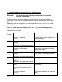
7. Possible Malfunctions of the Installation
Warning:
Only authorised and duly instructed personnel is allowed to
eliminate malfunctions.
The occurrence of a possible malfunction is indicated on the operating unit with a
flashing "E" in line 2 with the corresponding error number and the light + buzzer goes
on.
Depending upon the malfunction, the whole installation or only a part of it (i.e. humidity system) is switched off.
Once the failure has been repaired, press the "S" key to acknowledge the failure message. The installation restarts then and can be operated as usual.
Depend of the equipment
Error
number
E0
E1
E2
E3
E4
E5
E6
Meaning of the error number
To repair the failure
Thermal protection of test chamber
ventilator 1 released.
02-F2.1
Installation completely disconnected
Temperature limiter in test chamber
released
01-F1.1
Installation completely disconnected
Maximum pressure governor in refrigeration cycle released
03-F3.1
Installation completely disconnected
Specimen protection device (option)
released
09-A1
Installation completely disconnected
Reaction of temperature limiter software
08-B1.1
Installation completely disconnected
Reaction of humidity limiter software
08-B2
Humidity system is disconnected.
Temperature control continues to
run
Thermal protection of ventilator on
condenser released.
03-F5.2
Installation completely disconnected
Check whether the test chamber ventilator is dirty, easy-running and check the
cooling air supply.
Inform CTS after-sales service
Clean condenser or check air supply, for
water-cooled installations, check the
cooling water supply.
Check adjusted index value as well as
pre-set limits on specimen protection
device
Check adjusted index value as well as
pre-set limits
Check adjusted index value as well as
pre-set limits
Check whether the ventilator is dirty,
easy-running and check the cooling air
supply.
C:\Program Files\Apache Group\Apache2\htdocs\cdsconv\results\988156977\CT40-500UserManual.doc / 31.01.2005 2:52
/ Rg
43
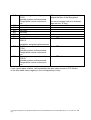
E7
E8
E9
E10
E11
E12
E13
E14
E15
E16
Water shortage in humidity system.
07-S2
Humidity system is disconnected.
Temperature control continues to
run.
not used
not used
not used
not used
not used
not used
Pt 100 air inlet is defect
08-B1.2
Fill the reservoir canisters with water or
replace the filter of the filling pump.
(this error message has to be acknowledge with the "S" key)
Inform CTS after-sales service
Installation completely disconnected
Pt 100 waterbath is defect
Inform CTS after-sales service
07-B4
Humidity system is disconnected.
Temperature control continues to
run.
Suction pressure sensor is defect
Inform CTS after-sales service
03-B12
Humidity system is disconnected.
Temperature control continues to
run.
If you cannot repair a failure, call immediately the after-sales service of CTS GmbH
or the after-sales service agency in the corresponding country.
C:\Program Files\Apache Group\Apache2\htdocs\cdsconv\results\988156977\CT40-500UserManual.doc / 31.01.2005 2:52
/ Rg
44
8. Maintenance
Our installations are to a large extent free of any maintenance. Regular attendance
and maintenance do however contribute to a failure-free operation of your installation.
Maintenance jobs on the systems belonging to this installation are to be performed
only by the manufacturer or his authorised representations.
Caution:
The owner or the operator must ensure that the installation is
checked in a satisfying way, regularly monitored and maintained.
Caution:
Only the manufacturer or his authorised representatives are
authorised to proceed to maintenance or resp. repair works on
the systems of the installation, in particular filling, draining and
replacing of the refrigerating agents or of the heat transfer liquids.
Attention:
Use only genuine spare parts.
Warning:
For any maintenance job, the main switch must be off and secured against any restart.
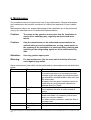
Some maintenance jobs which can be performed by trained personnel are listed here
below.
Time
Element
Work description
After each test
Test chamber
Clean test chamber.
To prevent corrosion it is necessary to wash
the sides of the test space as well as the bowltype humidifier and dehumidifier after each test
with clear water.
Scrapes in the test space container can be removed with an usual domestic cleanser for
stainless steel (i.e. Sidol).
Test chamber
Clean the seals with clear water.
door
Check whether the door is really sealed all
around.
Condenser
Check dust deposits on the air-cooled condenser and clean it if necessary with a hand
brush or a vacuum cleaner.
For water-cooled condenser, clean the filter in
the water feed.
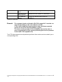
If necessary
Humidity system Clean the reservoir canisters with clear water.
Deionization de- see separate operating instructions
vice*
C:\Program Files\Apache Group\Apache2\htdocs\cdsconv\results\988156977\CT40-500UserManual.doc / 31.01.2005 2:52
/ Rg
45
Compressed-air
drier*
Inlet filter of humidity system
Test chamber
lighting
see separate operating instructions
Replace the filter (order no. 10001092)
Change the halogen bulb (order no.
10000117).
*optional equipement
Remark:
The repeated checks as listed in EN 378-2 appendix C must be carried out depending on the case which occurred.
CTS or their authorised representative carry out these repeated
checks if one of the listed conditions is given.
The owner or the operator of the installation must order once a
year an examination of the security switching devices for pressure
control (EN 378-2 appendix C6).
The CTS after-sales service department performs these works and can submit you a
corresponding offer.
C:\Program Files\Apache Group\Apache2\htdocs\cdsconv\results\988156977\CT40-500UserManual.doc / 31.01.2005 2:52
/ Rg
46
9. Index
Additional functions ..........................24
Adjusting the temperature index value
.........................................................23
Application in accordance with the
purpose / Misuse ................................7
Automatic Editor ...............................32
Automatic Mode................................26
Behaviour in Case of Emergency .......9
Closing down ....................................15
Control in general .............................20
Control unit of the installation ...........20
CTS-Chamber, test volume 25 ltr .....16
Description of the installation............19
Digital inputs (option) ........................20
Digital outputs (option)......................20
Display of power outage times..........39
EC Directives and National Legislation
...........................................................5
Electrical Norms .................................5
General Information............................4
Handling of the operating instructions 4
Head of programme..........................32
Installation and preparation of the test
cabinet ..............................................10
Interface configuration ......................30
Interface ports...................................21
Interface protocol CTS control <--> PC
.........................................................40
Limits of the machine..........................7
Maintenance .....................................47
Malfunction indication .......................25
Malfunctions .....................................45
Manual Mode....................................23
Mechanical Norms..............................5
Operation with CTS operating unit....22
Position of accessories and
connections + dimensions ............... 16
Possible Malfunctions of the
Installation........................................ 45
Programme body ............................. 32
Programme end: .............................. 36
Protection equipment......................... 9
Read analog parameters ................. 41
Read programme status .................. 43
Read status...................................... 42
Read text of error............................. 44
Read time ........................................ 41
Requirements for the place of
installation........................................ 10
Safety data sheets ............................. 9
Safety devices / Protection caps........ 8
Safety regulations .............................. 5
Safety regulations and equipments.... 5
Safety remarks................................... 6
Set analog parameters .................... 41
Set time ........................................... 40
Shutdown, disposal.......................... 15
Signal words ...................................... 6
Software - Temperature limiter ........ 29
Special menus ................................. 39
Specimen protection device (option) 20
Start/stop programme ...................... 43
Starting the installation .................... 23
Starting-up ....................................... 14
Starting-up: Preparation and Execution
......................................................... 10
Stopping the installation................... 24
Technical performance characteristics
......................................................... 17
type designation................................. 4
Warning against remaining dangers .. 8
Warranty and liability ......................... 6
C:\Program Files\Apache Group\Apache2\htdocs\cdsconv\results\988156977\CT40-500UserManual.doc / 31.01.2005 2:52
/ Rg
47