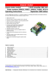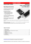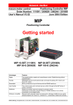
1
maxon motor
maxon motor control
Operating Instructions
1-Q-EC Amplifier DEC 50/5
Order number 230572
October 2008 Edition
The DEC (Digital EC Controller) is a 1-quadrant amplifier for controlling electronically commutated (brushless)
DC motors.
• Digital speed control
• Maximum speed: 120 000 rpm (motor with 1 pole pair)
• Operates as speed control, current control or open loop
speed control
• /Brake, direction and /disable input
• AUX connection: adjustable function
(+5 V output or input for changing speed)
• Status indicator with red and green LED
• Set value input through built-in potentiometer (several
speed ranges can be selected) or through
analogue set value input (0 ... +5 V)
• Maximum current limit adjustable
• Gain can be adjusted in two stages
• Adjustable speed ramp
• Protection against heat overload
• Blockage protection (current limit for blocked motor)
• Plug-in terminal clamp
Table of Contents
1
2
3
4
5
6
7
8
9
10
11
12
13
Safety Instructions ..............................................................................................................................................2
Performance Data ..............................................................................................................................................3
Minimum External Wiring for Different Modes of Operation...............................................................................4
Operating Instructions ........................................................................................................................................6
Inputs and Outputs .............................................................................................................................................8
Switch Functions ..............................................................................................................................................12
Speed Ranges..................................................................................................................................................12
Potentiometer Functions...................................................................................................................................13
Operating Status Display..................................................................................................................................14
Protection .........................................................................................................................................................15
EMC-compliant installation...............................................................................................................................15
Block Diagram ..................................................................................................................................................16
Dimension Drawing ..........................................................................................................................................16
The latest edition of these operating instructions may be found in the internet as a PDF-file under
www.maxonmotor.com category “Service & Downloads”, Order number 230572.
maxon motor
1-Q-EC Amplifier DEC 50/5
1
Operating Instructions
Safety Instructions
Skilled Personnel
Only experienced, skilled personnel should install and start the equipment.
Statutory regulations
The user must ensure that the amplifier and the components belonging to it are
assembled and connected according to local statutory regulations.
Load disconnected
For initial operation, the motor should be free running, i.e. with the load
disconnected.
Additional safety equipment
Any electronic apparatus is, in principle, not fail-safe. Machines and apparatus
must therefore be fitted with independent monitoring and safety equipment. If the
equipment breaks down, if it is operated incorrectly, if the control unit breaks
down or if the cables break, etc., it must be ensured that the drive or the complete
apparatus is kept in a safe operating mode.
Repairs
Repairs may only be carried out by authorised personnel or the manufacturer. It is
dangerous for the user to open the unit or carry out any repairs.
Danger
Ensure that no apparatus is connected to the electrical supply during installation
of the DEC 50/5. After switching on, do not touch any live parts!
Max. supply voltage
Make sure that the supply voltage is between 10 and 50 VDC. Voltages higher
than 60 VDC or of wrong polarity will destroy the unit.
Short circuit and earth fault
The amplifier is not protected against:
winding short circuits, winding short circuits against ground safety earth or Gnd!
Electrostatic sensitive device (ESD)
2 maxon motor control
October 2008 Edition / Doc.No. 544910-06 / subject to change
maxon motor
Operating Instructions
2
1-Q-EC Amplifier DEC 50/5
Performance Data
2.1 Electrical data
Supply voltage VCC (Ripple < 5 %)..............................................................................10 - 50 VDC
Max. output voltage........................................................................................................ 0.95 · VCC
Continuous output current Icont ..................................................................................................5 A
Max. output current Imax...........................................................................................................10 A
Switching frequency............................................................................................................ 39 kHz
Max. speed (motor with 1 pole pair)........................................................................... 120 000 rpm
2.2 Inputs
Speed ..................................................................................................... analogue input (0 ... 5 V)
Resolution: 1024 steps
/Disable ............................................................................ TTL, CMOS (5V) or switch against Gnd
Direction.........................................................................TTL, CMOS (5V) ) or switch against Gnd
/Brake ............................................................................TTL, CMOS (5V) ) or switch against Gnd
Hall sensor ........................................................................................................................... 1, 2, 3
2.3 Inputs / outputs
AUX (configurable).............................................................................digital input / +5 VDC output
2.4 Voltage outputs
Hall sensors supply voltage VCC Hall .....................................................7 ... 12 VDC, max. 30 mA
2.5 Motor connections
Motor winding 1
Motor winding 2
Motor winding 3
2.6 Trim potentiometers
Speed 1, Speed 2 / Ramp, Imax, gain
2.7 LED indicator
Operating indicator: green LED
Error indicator: red LED
2.8 Ambient temperature / humidity range
Operation ................................................................................................................... -10 ... +45°C
Storage ...................................................................................................................... -40 ... +85°C
No condensation ........................................................................................................... 20 ... 80 %
2.9 Protective functions
Heat monitoring of power stage ..................................................................................... T > 100°C
Blockage protection .................. Motor current limit, if motor shaft is blocked for longer than 1.5 s
2.10 Mechanical data
Weight...................................................................................................................... approx. 155 g
Dimensions (L x W x H) ..........................................................see dimension drawing, chapter 13
Mounting plate ...................................................................................................... for 4 screws M3
Mounting hole separation............................................................................................ 87 x 39 mm
2.11 Terminals
PCB clamps (plug-in terminal clamps) ..............................................................................15 poles
Pitch ............................................................................................................................. 3.5 mm
2
2
suitable for wire cross section ..... 0.14...1mm multiple-stranded or 0.14...1.3mm single wire
AWG 16-26
October 2008 Edition / Doc.No. 544910-06 / subject to change
maxon motor control 3
maxon motor
1-Q-EC Amplifier DEC 50/5
3
Operating Instructions
Minimum External Wiring for Different Modes of Operation
3.1 Speed control
4 maxon motor control
October 2008 Edition / Doc.No. 544910-06 / subject to change
maxon motor
Operating Instructions
1-Q-EC Amplifier DEC 50/5
3.2 Current control and open loop speed control
October 2008 Edition / Doc.No. 544910-06 / subject to change
maxon motor control 5
maxon motor
1-Q-EC Amplifier DEC 50/5
4
Operating Instructions
Operating Instructions
4.1 Power supply layout
Any available power supply can be used, as long as it meets the minimum requirements set out below.
During set up and adjustment phases, we recommend separating the motor
mechanically from the machine to prevent damage from uncontrolled motion.
Power supply requirements
Output voltage
Ripple
Output current
VCC min. 10 VDC; VCC max. 50 VDC
<5%
depending on load,
continuous max. 5 A
acceleration, short-time max. 10 A
The required voltage can be calculated as follows:
Known values
Ö Operating torque MB [mNm]
Ö Operating speed nB [rpm]
Ö Nominal motor voltage UN [V]
Ö Motor no-load speed at UN, n0 [rpm]
Ö Speed/torque gradient of motor ∆n/∆M [rpm/mNm]
Sought values
Ö Supply voltage VCC [V]
Solution
VCC =
UN
∆n
1
⋅MB) ⋅
+ 1V
⋅ (n B +
∆M
0.95
n0
Choose a power supply capable of supplying this calculated voltage under load.
The formula takes into account a max. PWM cycle of 95 % and a 1 volt max.
voltage drop at DEC 50/5.
Note
Please note chapter 5.1.5, “/Brake” function when using the “/brake” input!
6 maxon motor control
October 2008 Edition / Doc.No. 544910-06 / subject to change
maxon motor
Operating Instructions
1-Q-EC Amplifier DEC 50/5
4.2 Adjusting the potentiometers
4.2.1
Pre-adjustment
P3 Imax
P1 Speed 1
DEC units in the original packing are already pre-set.
P2 Speed 2 / Ramp
With the pre-adjustment, the potentiometers are set in a preferred position.
Pre-adjustment of potentiometers
P1
Speed 1
50 %
P2
Speed 2 / Ramp
50 %
P3
Imax
50 %
Note
Left end stop of potentiometers:
Right end stop of potentiometers:
4.2.2
Minimum value
Maximum value
Adjustment
Digital speed control
1.
2.
3.
Digital current control
1.
2.
Depending on operating mode selected, predetermine set value so that
required speed is reached. If necessary, adjust max. speed with switch
S5 and S6 (see chapter 7, “Speed Ranges”).
Adjust potentiometer P3 Imax to required limiting value.
Maximum current in the 0 … 10 A range can be adjusted in linear fashion
with potentiometer P3.
Adjust switch S2 gain to required amplification
(S2 OFF: gain high, S2 ON: gain low)
Important: If the motor is unsteady, vibrates or makes noises, the selected amplification is too high. Switch S2 must be set at ON.
Adjust potentiometer P1 Speed 1 to required speed limit. Maximum
speed in the 500 ... 25 000 rpm range (motor with 1 pole pair) can be
adjusted in linear fashion with potentiometer P1, and is independent of
the position of the switches S5 and S6 (see chapter 7, “Speed Ranges”).
Predetermine set value at “Speed” input so that required torque is
reached.
Note
A set value in the 0 ... 5 V range at the “Speed” input is equal to a current
adjustment range of approx. 0 … 5 A.
Band width of current control: approx. 15 Hz
Digital open loop
speed control
1.
2.
Predetermine set value at “Speed” input so that required speed is
reached. The set value range of 0 ... +5 V is equal to a motor voltage
range of 0 V ... VCC. The maximum speed is determined by the supply
voltage and the speed constant of the motor and is independent of the
position of the switches S5 and S6.
Adjust potentiometer P3 Imax to required limiting value.
Maximum current in the 0 … 10 A range can be adjusted in linear fashion
with potentiometer P3.
October 2008 Edition / Doc.No. 544910-06 / subject to change
maxon motor control 7
maxon motor
1-Q-EC Amplifier DEC 50/5
5
Operating Instructions
Inputs and Outputs
5.1 Inputs
5.1.1
Set value “Speed”
The analogue set value is predetermined at the “Speed” input.
The set value input is used for the following operating modes: speed control,
current control and open loop speed control.
The “Speed” input is protected against overvoltage.
Input voltage range
Input impedance
Continuous overvoltage protection
0 ... +5 V (ref: Gnd)
> 1 MΩ (in the 0 ... +5 V range)
-50 ... +50 V
Use of external potentiometer
When using an external potentiometer, the AUX output (switch S1 AUX ON)
can be used as +5 V reference.
Recommended resistance value of potentiometer: 10 kΩ
Note
0 V equals the minimum speed (see chapter 7, “Speed Ranges”)
5.1.2
“/Disable”
Disabling or blocking the power stage.
If the input is not wired or the applied voltage is greater than 2.4 V, the amplifier
is activated. A speed ramp will be performed during acceleration.
If the input is placed at Gnd-potential or the applied voltage is lower than 0.8 V,
the power stage is blocked and the motor shaft freewheels and slows down.
The “/Disable” input is protected against overvoltage.
Input voltage range
Input impedance
Continuous overvoltage protection
Delay time
“/Disable” active
“/Disable” inactive
0 ... +5 V
33 kΩ pull-up resistor at +5 V
-50 ... +50 V
approx. 12 ms
Input open or
input voltage > 2.4 V
Set input to Gnd or
input voltage < 0.8 V
Note
If the switch adjuster was changed, the new settings are adopted through a
disable-enable procedure.
8 maxon motor control
October 2008 Edition / Doc.No. 544910-06 / subject to change
maxon motor
Operating Instructions
5.1.3
1-Q-EC Amplifier DEC 50/5
“Direction”
When the level changes, the motor slows down in an uncontrolled fashion (as
windings are short-circuited, see also chapter 5.1.5, “/Brake” function) and
accelerates in the opposite direction, until the nominal speed is reached
again. A speed ramp is only used during acceleration.
The “Direction” input is protected against overvoltage.
Input voltage range
Input impedance
Continuous overvoltage protection
Delay time
0 ... +5 V
33 kΩ pull-up resistor at +5 V
-50 ... +50 V
approx. 12 ms
Input open or
input voltage > 2.4 V
Set input to Gnd or
input voltage < 0.8 V
Clockwise (CW)
Counter-clockwise (CCW)
If the direction is changed with a rotating motor shaft, the limitations described
in chapter 5.1.5, "/Brake" function must be observed, or the amplifier may be
damaged.
5.1.4
Ramp function
The ramp function enables the motor speed to have a controlled run-up when it
starts up and if set values change.
Acceleration time is adjusted at the potentiometer P2 Ramp and relates to the
maximum speed in the currently chosen speed range (see chapter 7, “Speed
Ranges”).
adjustable acceleration time
on the potentiometer P2 Ramp
Left end stop
Right end stop
Pitch
Example:
Potentiometer P2 Ramp:
Change in “Speed” set value:
approx. 20 ms ... approx. 10 s
approx. 20 ms
approx. 10 s
linear
approx. 1.0 s/pitch
40 %
0 V to 3 V
Acceleration time to rated speed
Acceleration time =
3V
⋅ 40 % ⋅ 10 s = approx. 2.4 s
5V
Note
The minimum acceleration time can only be reached if the gain is high and the
drive sufficiently dynamic.
October 2008 Edition / Doc.No. 544910-06 / subject to change
maxon motor control 9
maxon motor
1-Q-EC Amplifier DEC 50/5
5.1.5
Operating Instructions
“/Brake” function
If the input is not wired or the applied voltage is greater than 2.4 V, the /brake
function is deactivated.
If the input is placed at Gnd-potential or the applied voltage is lower than 0.8 V,
the /brake function is activated and the motor shaft slows down to a halt, shortcircuiting the motor windings. The motor windings remain short-circuited until
the /brake function is deactivated.
The /brake function is also used with an active /disable function.
The “/Brake” input is protected against overvoltage.
Input voltage range
Input impedance
Continuous overvoltage protection
Max. brake current
Delay time
0 ... +5 V
33 kΩ pull-up resistor at +5 V
-50 ... +50 V
30 A
approx. 12 ms
Input open or
input voltage > 2.4 V
Set input to Gnd or
input voltage < 0.8 V.
“/Brake” inactive
“/Brake” active
The maximum permitted brake speed is limited by the maximum permitted
short-circuit current and maximum kinetic energy:
• I <= 30 A
• Wk <= 20 Ws
the values can be calculated as follows:
The maximum permitted brake speed can be calculated from the
motor data:
max. permitted brake
speed limited by brake
current
(I = 30 A)
n max = 30 A ⋅ k n ⋅ (RPh − Ph + 0.05 Ω )
[rpm]
kn = Speed constant [rpm/V]
RPh-Ph = Terminal resistance phase-phase [Ω]
With the given moment of inertia, the maximum speed can be determined
using the following formula:
max. permitted brake
speed limited by kinetic
energy (Wk = 20 Ws)
nmax =
365
⋅10 000 [rpm]
JR + JL
JR = Rotor inertia [g cm2]
JL = Load inertia [g cm2]
•
•
10 maxon motor control
October 2008 Edition / Doc.No. 544910-06 / subject to change
maxon motor
Operating Instructions
5.1.6
1-Q-EC Amplifier DEC 50/5
“AUX”
The “AUX” terminal can be used as input or output, depending on the switch
position.
The “AUX” terminal is only protected against overvoltage if switch S1 is open.
Switch S1 closed
Switch S1 opened
5.1.7
Function
Output voltage
Internal resistance
Output current, designed for an external potentiometer >=10 kΩ
Voltage output
+5 VDC ± 5 %
220 Ω
Function
Input voltage range
Input impedance
Continuous overvoltage protection
Speed change
0 ... +5 V
33 kΩ pull-up resistor at +5 V
-50 ... +50 V
Speed setting with potentiometer
Speed 1
Speed setting with potentiometer
Speed 2
Input open or
input voltage > 4.0 V
Set input to Gnd or
input voltage < 1.0 V
500 µA
“Hall sensor 1”, “Hall sensor 2”, “Hall sensor 3”
Hall sensors are needed for detecting rotor position.
"Hall sensor" inputs are protected against overvoltage.
Input voltage range
Input impedance
Voltage value “low”
Voltage value “high”
Continuous overvoltage protection
0 ... +5 V
15 kΩ pull-up resistor at +5 V
max. 0.8 V
min. 2.4 V
-50 ... +50 V
Suitable for Hall effect sensors IC using Schmitt trigger and open collector output.
5.2 Outputs
5.2.1
“VCC Hall”
Powering the Hall sensors.
Output voltage
Max. output current
October 2008 Edition / Doc.No. 544910-06 / subject to change
7 ... 12 VDC
30 mA (current limited)
maxon motor control 11
maxon motor
1-Q-EC Amplifier DEC 50/5
Switch Functions
7
Speed Ranges
speed range
(motor with
1 pole pair)
6
Operating Instructions
In the speed control mode the set value range (0 ... +5 V) is equal to the following speed ranges:
Switch S5 and S6
Motor with 1 pole pair
Type of motor
Motor with 4 pole pairs
Motor with 8 pole pairs
500 ... 6 000 rpm
125 ... 1 500 rpm
67 ... 750 rpm
500 ... 25 000 rpm
125 ... 6 250 rpm
67 ... 3 125 rpm
500 ... 60 000 rpm
125 ... 15 000 rpm
67 ... 7 500 rpm
500 ... 120 000 rpm
125 ... 30 000 rpm
67 ... 15 000 rpm
Note
• Independent of the position of the switches S5 and S6, the maximum
speed can, with the help of P1 Speed, be adjusted only in the range 500 ...
25 000 rpm (2 pole motors) in current control mode. For multi-pole motors
the speed range is shown in the table above.
• Operating as an open loop speed control the 0 V set value is equal to a
motor voltage of 0 V and thus a speed of 0 rpm. Independent of the position of the switches S5 and S6, the maximum speed is given by the supply
voltage and the speed constant of the motor.
12 maxon motor control
October 2008 Edition / Doc.No. 544910-06 / subject to change
maxon motor
Operating Instructions
8
1-Q-EC Amplifier DEC 50/5
Potentiometer Functions
The following table shows which potentiometer is active in which operating
mode.
Mode
9
9
With external
set value
0 ... +5 V
With external
set value
0 ... +5 V
9
Open loop
speed control
Set value with external potentiometer
Set value with external potentiometer
9
P1
Speed 1
Current control
With 2
different speeds
With external
set value
0 ... +5 V
Set value with external potentiometer
Function of potentiometers
Set value with internal potentiometer P1
Speed control
(closed loop)
9
9
9
P2
Speed 2
P2
Ramp
P3
Imax
9
9
9
9
9
9
October 2008 Edition / Doc.No. 544910-06 / subject to change
9
maxon motor control 13
maxon motor
1-Q-EC Amplifier DEC 50/5
9
Operating Instructions
Operating Status Display
Red and green LEDs show the operating status.
Definition
LED on
LED off
9.1 No LED
Reason:
• No supply voltage
• Fuse blown
• Wrong polarity of supply voltage
• Hall sensors supply voltage VCC Hall is short-circuited
9.2 Green LED
Flashing type (green LED)
LED on
Operating status
Amplifier active
/Disable function active
/Brake function active
9.3 Red LED flickers or flashes intermittently
The controller recognises invalid conditions in the Hall sensor inputs.
Reason:
• Hall sensors not connected or incorrectly connected
• Intermittent Hall sensor supply lines
• Excessive interference to Hall sensor supply lines
(Solution: change supply line feeds, use shielded cable)
• Faulty Hall sensors in motor
9.4 Red LED flashes regularly
The following error messages can be distinguished depending on flashing type:
Flashing type (red LED)
14 maxon motor control
Error message
Thermal overload protection is active
• Motor shaft is blocked
• Load too great
• Imax setting too low
• No winding connection
When switched on, the controller
recognises invalid conditions in the
Hall sensor inputs => check Hall
sensor wiring and Hall sensor signals
An invalid operating mode was set on
switches S3-S6
October 2008 Edition / Doc.No. 544910-06 / subject to change
maxon motor
Operating Instructions
1-Q-EC Amplifier DEC 50/5
10 Protection
10.1 Protection against heat overload
If the power stage temperature exceeds a limit of around 100°C for longer than 1.5 s, the
output stage is switched off.
The error mode is shown in diagram form (see chapter 9 “Operating Status Display”).
If the power stage temperature falls below 80°C, the motor is restarted. A speed ramp
will be performed during acceleration.
10.2 Blockage protection
If the motor shaft is blocked for longer than 1.5 s, the current limit is set at 4.2 A, provided the current limit was not set at a lower value via the Imax potentiometer.
Note
The blockage protection is not active in current control mode.
11 EMC-compliant installation
Power supply (+VCC - Power Gnd)
•
No shielding normally required.
•
Star point-shaped wiring if several amplifiers are supplied by the same power supply.
Motor cable (> 30 cm)
•
Shielded cable highly recommended.
•
Connect shielding on both sides:
DEC 50/5 side:
Bottom of housing.
Motor side:
Motor housing or with motor housing mechanical design with low resistive connection.
•
Use separate cable.
Hall sensor cable (> 30 cm)
•
Shielded cable highly recommended.
•
Connect shielding on both sides:
DEC 50/5 side:
Bottom of housing.
Motor side:
Motor housing or with motor housing mechanical design with low resistive connection.
•
Use separate cable.
Direct connection motor/Hall cable (≤ 30 cm) on DEC 50/5
•
Shield casing over motor/Hall connection cable
•
Connect shielding on both sides
or
•
Lowest resistive connection of motor housing and bottom of DEC 50/5 housing
•
Cable design of motor/Hall connection cable as close as possible with aforementioned
connection
Analogue signals (AUX, Speed)
•
No shielding normally required
•
Use cable shielding with analogue signals with small signal level and electromagnetically
harsh environment
•
Normally connect shielding on both sides. Place shielding on one side if there are 50/60
Hz interference problems.
Digital signals (Disable, Direction, Brake)
•
No shielding necessary.
See also block diagram in chapter 12.
In practical terms, only the complete equipment, comprising all individual components (motor, amplifier, power supply unit, EMC filter, cabling etc.) can undergo an EMC test to ensure
interference-free CE-approved operation.
October 2008 Edition / Doc.No. 544910-06 / subject to change
maxon motor control 15
maxon motor
1-Q-EC Amplifier DEC 50/5
Operating Instructions
12 Block Diagram
Case
+5V
Ground
Safety
Earth
+7...+12V
+5V
Supply
Hall Sensor 1
earth
optional
+5V
7A
+5V
+VCC 10...50V
+5V
Power Ground
Hall Sensor 2
Power
Driver
+5V
+5V
MOSFET
3-phase
brigde
Motor winding 1
Motor winding 2
8-Bit
Micro
Controller
Hall Sensor 3
+7...+12V
Motor winding 3
Current
detect
Current
limit
30mA
+VCC Hall
Gnd
+5V
+5V
+5V
/Disable
P1 Speed 1
+5V
+5V
+5V
Direction
Note:
taphole on DEC 50/5
earth
optional
P2 Speed 2 / Ramp
+5V
+5V
+5V
/Brake
P3 Ima x
+5V
+5V
AUX
+5V
S1
+5V
Speed
13 Dimension Drawing
Dimensions in [mm]
16 maxon motor control
October 2008 Edition / Doc.No. 544910-06 / subject to change