1
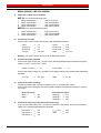
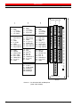
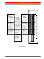
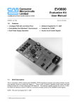
maxon motor
maxon motor control
Positioning Controller MIP
Order Number: 111091 / 200629 / 246244 / 251669
User's Manual V3.52
June 2004 Edition
MIP
Positioning Controller
Getting started
MIP 10-SET (111091)
MIP 50-E (200629)
MIP 20-SET (251669)
MIP 100-E (246244)
Advantages
Features
Digital
Fully digital position, speed and current/torque control. Digital trimming without
potentiometers.
MIP50/MIP100 drive both electronically commuted (brushless) EC motors and
brush DC motors.
Build up networks of up to 64 drives with the RS485 serial bus.
Flexible
Extendable
User friendly
Interfaces
Software compatible
The control modes and command set are uniform through all the MIP family of
motion controllers.
Digital and analog inputs and outputs for process control.
Commands can be send using the RS232 or RS485 interface or as a binary
combination on the digital inputs.
Delivered with advanced setup and tuning tools, Windows 32-Bit DLLs as well as
sample programs for Visual C++, Borland C++, Visual Basic, Delphi and LabView.
maxon motor
User's Manual
Positioning Controller MIP
Table of contents
1. Safety instructions...................................................................................................................................... 3
2. Technical data............................................................................................................................................ 4
3. Getting started............................................................................................................................................ 5
Step 1
Install the software ........................................................................................................................ 5
Step 2
Set up your hardware.................................................................................................................... 6
Step 3
Start the MIP Studio application.................................................................................................. 12
Step 4
Communication checklist / panel 1: Hardware set-up................................................................. 13
Step 5
Communication checklist / panel 2: PC communication settings ............................................... 14
Step 6
Communication checklist / panel 3: MIP communication settings .............................................. 14
Step 7
Communication checklist / panel 4: Download new firmware..................................................... 15
Step 8
Check the firmware version......................................................................................................... 15
Step 9
Download the firmware ............................................................................................................... 16
Step 10
Configure the system parameters............................................................................................... 18
Step 11
Check the communication parameters ....................................................................................... 19
Step 12
Define the drive characteristics ................................................................................................... 19
Step 13
Define the safety settings............................................................................................................ 22
Step 14
Define the regulation gains ......................................................................................................... 23
Step 15
Define the homing parameters.................................................................................................... 26
Step 16
Test your drive system ................................................................................................................ 27
Step 17
Select and configure the operating mode ................................................................................... 28
4. Series production ..................................................................................................................................... 30
Important Notice
The information contained in this manual refers to the firmware version 3.52. Since on MIP controllers the
firmware resides in Flash memory you have the possibility to update the firmware of your card. The latest
edition of these short instructions, additional documentation and software for the MIP may also be found in
the Internet under www.maxonmotor.com category “Service”, subdirectory “Downloads”.
Although maxon motor endeavors to maintain a high level of compatibility with past firmware versions, some
functions or features may behave differently or be missing in older version. maxon motor ag or its representatives will not endorse any liability for damages (malfunction of equipment, loss of production etc.) resulting
from incompatibility of different firmware versions.
Also maxon motor ag or its representatives will not be held for responsible for damages resulting from
inaccuracies or omissions in the present manual.
2 maxon motor control
June 2004 Edition / Subject to change
maxon motor
Positioning Controller MIP
User's Manual
1. Safety instructions
Skilled Personnel
Only experienced, skilled personnel shall perform installation and starting of the equipment.
Statutory Regulations
The user must ensure that the motor controller and the components belonging to it are
assembled and connected according to local statutory regulations.
Load Disconnected
For primary operation the motor should be free running, i.e. with the load disconnected.
Additional Safety Equipment
Electronic apparatus is basically not fail-safe. Machines and apparatus must therefore be
fitted with independent monitoring and safety equipment. It must be ensured that, if the
equipment breaks down, is operated incorrectly, the control unit breaks down or cables
break, etc. the drive or the complete apparatus is kept in a safe operating mode.
Repairs
Repairs may only be made by authorized personnel or by the manufacturer. It is dangerous
for the user to open the unit or make repairs to it.
Danger
Do ensure that during the installation no apparatus is connected to the electrical supply. After
switching on, do not touch any live parts.
Max. Supply Voltage
MIP10 & MIP20:
Make sure that the supply voltage is between 9 and 24 VDC (+/- 20%). Voltage higher than
24 VDC or wrong polarity will destroy the unit.
MIP50 & MIP100:
Make sure that the supply voltage is between 24 and 48 VDC (+/- 20%). Voltage higher than
48 VDC or wrong polarity will destroy the unit.
Electrostatic Sensitive Device (ESD)
Handle only in static safe work stations
June 2004 Edition / Subject to change
maxon motor control 3
maxon motor
User's Manual
Positioning Controller MIP
2. Technical data
MIP10-SET
Supply voltage +/- 20%
MIP20-SET
9 - 24 VDC
9 - 24 VDC
Power amplifier
Continuous current Icont
Peak current Imax
1.8 A
Built-in motor choke
External chokes
MIP100
24 - 48 VDC
24 - 48 VDC
4 Quadrant PWM / 60 kHz
2A
5A
10 A
2.4 A (5 s)
11 A (5 s)
3 A (200 ms)
13 A (200 ms)
digitally adjustable
2 A (5 s)
Current limit
Current resolution
MIP50
15 A (5 s)
20 A (200 ms)
5 mA
5 mA
15 mA
45 mA
1.0 mH
0.4 mH
3 x 0.16 mH
none
not required
required if motor inductance
< 0.16 mH
Control
< 0.09 mH
PID positioning control / 1 kHz sampling
PI current control / 8 kHz sampling
Max. speed
1000 qc/ms
Maximum speed [rpm] = 15’000’000 / encoder resolution
but no more than 65’000 [rpm]
(e.g. 30’000 rpm @ 500 imp/turn / 58’593 rpm @ 256 imp/turn)
I/O level
I/O polarity
Digital inputs
(ESD protected)
Logic levels
Analog inputs
(ESD protected)
Digital outputs
max. 24 V
configurable by jumper for high or low logic
Stop, Enable, Reference, Left/Right limits and
8 standard inputs
High-active:
Low-active:
12 - 24 VDC, typ. 7 mA @ 24 V
0 - 1.5 VDC, typ. 2 mA
2x0-5V
2x0-5V
2x0-5V
1x0-5V
4 + Error
4 + Error
6 + Error
6 + Error
24 V-switching current
max. 100 mA each
GND-switching current
total 450 mA
Other outputs
1 x PWM (50 kHz), free adjustable duty
Encoder input
1 x incremental encoder / RS422 (5 V, channel A, A\, B, B\, I, I\)
Max. input frequency
Communication
Form factor
Connector
Operating temperature
4 maxon motor control
250 kHz
RS232 & RS485 (max. 57 600 Baud)
Metal housing 132x114x31 mm
Single eurocard 3HE / 8TE
96-Pin
160-Pin
3 x 9-pol. DSUB
DIN 41612
DIN 41612
(COM, Encoder, Power / Motor)
Typ C
Typ C
1 x 25-pol. DSUB (I/O)
(Harting Harbus)
0 ... 40°C
June 2004 Edition / Subject to change
maxon motor
Positioning Controller MIP
User's Manual
3. Getting started
This document is a step by step procedure for installing and configuring your MIP motion controller. If
you follow this procedure you should quickly be able to work with your MIP controller. Please take the
time to read this document since it will answer most of the common questions.
This installation procedure is based on a new start-up tool named MIP Studio that should greatly
simplify the first steps with your MIP motion controller.
Step 1
Install the software
Install the software from the MIP CD-ROM. The CD-ROM contains all necessary information
and tools for installing and operating the MIP motion controllers
(manuals, firmware, and tools, Windows DLLs).
System requirements:
Win95, Win98, Win ME, Windows NT® 4, Windows 2000, XP
Pentium processor, 64 MB RAM
50 MB free storage space on hard disk
Screen resolution 1024 x 768 pixels at 256 colors
Follow the next instructions to install the software package on your computer:
a)
Insert the CD-ROM
Insert the MIP CD-ROM into the CD-ROM drive of your computer.
b)
Start the installation program <MIP_CD-ROM.exe>
Browse your CD-ROM drive with the Windows explorer and double click the ‘MIP_CDROM.exe’ item to start the installation program.
Alternatively select the entry ‘Execute’ in the start menu and enter the command ‘x:\MIP_CDROM’ (where ‘x’ is the letter of your CD-ROM drive).
c)
Follow the instructions during the installation program
During the installation procedure you will be asked for an installation directory.
(Recommendation: C:\ProgramFiles\maxonmotor MIP CD-ROM)
d)
Check the new shortcuts and items in the start menu
A new entry ‘maxon motor MIP CD-ROM’ is added to the start menu that gives access to all
the software components. Shortcuts to the most important MIP tools are added on your
desktop.
June 2004 Edition / Subject to change
maxon motor control 5
maxon motor
User's Manual
Step 2
Positioning Controller MIP
Set up your hardware
MIP10-SET (111091) / MIP20-SET (251669)
a)
Check the content of your material
You need the following parts:
• Order code 108971.............. MIP 10 in housing
or Order code 251649.............. MIP 20 in housing
• Order code 134795.............. MIP encoder cable
• Order code 108088.............. MIP motor/power cable
• Order code 133367.............. MIP RS232 cable
• Order code 108977.............. MIP Test connector
b)
Connect the MIP encoder cable
Connect the MIP encoder cable (Order code 134795) to the 9-pin DSUB connector P3 of the
MIP. The opposite side has to be connected to the 10-pin connector of the encoder cable.
c)
Connect the MIP motor/power cable
Connect the motor/power cable (Order code 108088) to the 9-pin DSUB connector P1 of the
MIP. On the opposite side, the banana plugs have to be connected to the power supply (9 - 24
VDC, min. 2 A). Connect the two small connectors with the motor terminals and check the
polarity (red = +, black = -).
Warning ! The control unit has no protection against wrong polarity or voltages higher than 24
VDC. There is also no protection against a short circuit of the motor connections !
d)
Connect the RS232 cable
Connect the RS232 cable (Order code 133367) to the 9-pin DSUB connector P4 of the MIP.
The opposite side has to be connected to a free RS232 port of your computer.
e)
Connect the MIP Test connector
Plug in the MIP Test connector to the I/O connector P2. If you do not use the MIP Test
connector, you have to wire the input STOP (Pin 6) with the supply voltage Vs (Pin 1) using a
switch with opening contact. If this wiring is missing, an error is generated at system start-up.
(Red LED is on, ERROR 40, Stop active).
Note: If you do not use the maxon motor cables, you have to do the wiring according to the
connector pin description given in the [MIP10-SET Hardware Reference] or the [MIP20-SET
Hardware reference].
6 maxon motor control
June 2004 Edition / Subject to change
maxon motor
Positioning Controller MIP
User's Manual
Picture 1: MIP10-SET, MIP20-SET wiring
Electro Magnetic Compatibility (EMC)
The power stage of the MIP works with pulse width modulation (PWM), which means there is
a square wave voltage with fixed frequency (60 kHz) and variable duty cycle running on the
motor lines. The edges of this square wave can cause electromagnetic interference. When
cabling your apparatus / machine, take care not to lay the motor cable along other sensitive
signals (like the signals of the encoder or the Hall sensors), especially over long distances. In
case of EMI problems, use a shielded motor cable (ground one side of the shield and connect
the other side to the motor housing).
June 2004 Edition / Subject to change
maxon motor control 7
maxon motor
User's Manual
Positioning Controller MIP
MIP50 (200629) / MIP100 (246244)
a)
Check the content of your material
MIP 50: You need the following parts:
•
•
or
or
Order code 200629 ................... MIP 50 eurocard
Order code 199950 ................... MIP 50 backplane
Order code 245963 ................... MIP 100 backplane
Order code 282437 ................... MIP training board
MIP100: You need the following parts:
•
Order code 246244 ................... MIP100 eurocard
•
Order code 245963 ................... MIP 100 backplane
or Order code 282437 ................... MIP training board
b)
Connect the encoder
Connect the encoder wires to the following MIP backplane terminals:
Index
Channel A
Channel B
Vcc (5V)
⇒
⇒
⇒
⇒
c17
a17
b17
c20, b20
Index/
Channel A/
Channel B/
GND
⇒
⇒
⇒
⇒
c18
a18
b18
c21, b21
Remark: You have to use an encoder with an RS422 line driver!
c)
Connect the power supplies
Connect the power supply (24 - 48 VDC) to the following MIP backplane terminals using thick
cables (1.5 mm2/ 10A, 2.5 mm2 / 20 A):
Power+ (24-48V) ⇒
P+
⇒
Power GND
P-
Connect the supply voltage VI/O (24 VDC) for the digital outputs to the following MIP backplane
terminals:
VI/O (24V)
d)
⇒
a10, b10
⇒
a9, b9
Connect the motor windings
The MIP 50 and the MIP 100 can be used for brush- or brushless DC motors.
Connect the motor windings to the following MIP backplane terminals according to the type of
your motor:
Brush DC motor
Motor +
Motor -
e)
GND
⇒
⇒
Brushless DC motor
W1
W2
Winding 1
Winding 2
Winding 3
⇒
⇒
⇒
W1
W2
W3
Connect the Hall sensor (brushless DC motor only)
If you use a brushless DC motor, you have to connect the hall sensor. Connect the following
cables to the following MIP backplane terminals:
Hall sensor 1
Hall sensor 2
Hall sensor 3
8 maxon motor control
⇒
⇒
⇒
a19
b19
c19
Vhall (15 V) ⇒
GND
⇒
a20
a21
June 2004 Edition / Subject to change
maxon motor
Positioning Controller MIP
f)
User's Manual
Connect the RS232 or RS485 communication cable
Connect the RS232 communication lines to the following MIP backplane terminals:
PC COM
9-pin DSUB
Pin 2 RxD
⇒
Pin 3 TxD
⇒
Pin 5 GND
⇒
MIP backplane
a16 TxD
c16 RxD
c14 GND
or connect the RS485 communication lines to the following MIP backplane terminals:
RS485
/RS485
g)
⇒
⇒
a15
c15
Connect the Stop input
Connect the following terminals using a Stop switch with opening contact.
Terminal b4 (Input Stop)
⇒
Terminal b10 (VI/O; 24 VDC)
If the Stop input is floating the error number 40 is generated at system start-up (red LED is
on). If the error appears despite of the correct wiring, you have to check that the I/O polarity
for the digital input group 2 is configured for high active logic. Please refer to the [MIP50
Hardware Reference] or [MIP100 Hardware Reference] for configuring the polarity of the
inputs.
Remark: If you do not have a voltage of 24 VDC available in your system, you can either
connect the Stop input to the 15V output (Terminal a20) or configure the inputs for low active
logic and connect the Stop input to GND (Terminal b9).
Electro Magnetic Compatibility (EMC)
The power stage of the MIP works with pulse width modulation (PWM), which means there is
a square wave voltage with fixed frequency (60 kHz) and variable duty cycle running on the
motor lines. The edges of this square wave can cause electromagnetic interference. When
cabling your apparatus / machine, take care not to lay the motor cable along other sensitive
signals (like the signals of the encoder or the Hall sensors), especially over long distances. In
case of EMI problems, use a shielded motor cable (ground one side of the shield and connect
the other one to the motor housing).
June 2004 Edition / Subject to change
maxon motor control 9
maxon motor
User's Manual
Positioning Controller MIP
maxon motor AG
c
↓
1:
2:
3:
4:
5:
GNDAnalog
VRef
GNDAnalog
Inp. Enable
Inp. Right
6:
7:
8:
9:
10:
11:
12:
13:
Dig. input 3
Dig. input 6
n.c.
GND
K_COM
GND
Dig. output 3
Dig. output 6
14:
15:
16:
17:
18:
19:
20:
21:
GND
RS485\
RS232 RxD
Enc. Index
Enc. Index\
Hallsensor 3
VCC (5 V)
GND
b
↓
c
↓
a
↓
1:
2:
3:
4:
5:
Anal. input 2
VRef
GNDAnalog
Input Stop
Input Left
6:
7:
8:
9:
10:
11:
12:
13:
Dig. input 2
Dig. input 5
Dig. input 8
GND
VI/O (24 V)
PWM-outp.
Dig. output 2
Dig. output 5
14:
15:
16:
17:
18:
19:
20:
21:
Res.TDO
Res.TDI
Res.TMS
Enc. B
Enc. B\
Hallsensor 2
VCC (5 V)
GND
P-:
P+:
P-:
W1:
W2:
W3:
Power GND
Power +
Power GND
Winding 1
Winding 2
Winding 3
1:
2:
3:
4:
5:
Anal. input 1
VRef
GNDAnalog
Input Reset
Input Ref.
6:
7:
8:
9:
10:
11:
12:
13:
Dig. Inp.1
Dig. Inp.4
Dig. Inp.7
GND
VI/O (24 V)
Outp. Error
Dig. output 1
Dig. output 4
14:
15:
16:
17:
18:
19:
20:
21:
Res.TCK
RS485
RS232 TxD
Enc. A
Enc. A\
Hallsensor 1
VHall (15 V)
GND
b
↓
1z
2z
3z
4z
5z
6z
7z
8z
9z
10z
11z
12z
13z
14
z
15
z
16
z
17
z
18
z
19
z
20
z
21
z
1z
2z
3z
4z
5z
6z
7z
8z
9z
10z
11z
12z
13z
14
z
15
z
16
z
17
z
18
z
19
z
20
z
21
z
a
↓
1z
2z
3z
4z
5z
6z
7z
8z
9z
10z
11z
12z
13z
14
z
15
z
16
z
17
z
18
z
19
z
20
z
21
z
P- z
P+z
P- z
W1z
W2z
W3z
⊗
•••
•••
•••
•••
•••
•••
•••
•••
•••
•••
•••
•••
•••
•••
•••
•••
•••
•••
•••
•••
•••
•••
•••
•••
•••
•••
•••
•••
•••
•••
•••
•••
⊗
⊗
Backplane
MIP 50 Vers. 1.0
38 mm
Picture 2: Pin Allocation MIP 50 Backplane
(order code 199950)
10 maxon motor control
June 2004 Edition / Subject to change
maxon motor
Positioning Controller MIP
User's Manual
maxon motor AG
c
↓
1:
2:
3:
4:
5:
6:
7:
8:
n.c.
VRef
GNDAnalog
Input Enable
Input Right
Dig. input3
Dig. input 6
n.c.
9:
10:
11:
12:
13:
14:
15:
16:
GND
K_COM
GND
Dig. output 3
Dig. output 6
GND
RS485\
RS232 RxD
17:
18:
19:
20:
21:
Enc. Index
Enc. Index\
Hall Sens. 3
VCC (5 V)
GND
b
↓
a
↓
1:
2:
3:
4:
5:
6:
7:
8:
n.c.
VRef
GNDAnalog
Input Stop
Input Left
Dig. input 2
Dig. input 5
Dig. input 8
9:
10:
11:
12:
13:
14:
15:
16:
GND
VI/O (24 V)
PWM-Outp.
Dig. output 2
Dig. output 5
ReservedTDO
ReservedTDI
ReservedTMS
17:
18:
19:
20:
21:
Enc. B
Enc. B\
Hall Sens. 2
VCC (5 V)
GND
P-:
P-:
P+:
W1:
W2:
W3:
Power GND
Power GND
Power +
Winding 1
Winding 2
Winding 3
c
↓
b
↓
1:
2:
3:
4:
5:
6:
7:
8:
Anal. inp. 1
VRef
GNDAnalog
Input Reset
Input Ref.
Dig. input 1
Dig. input 4
Dig. input 7
1z
2z
3
9:
10:
11:
12:
13:
14:
15:
16:
GND
VI/O (24 V)
Outp. Error
Dig. output 1
Dig. output 4
ReservedTCK
RS485
RS232 TxD
9z
17:
18:
19:
20:
21:
Enc. A
Enc. A\
Hall Sens. 1
VHall (15 V)
GND
z
4
z
5z
6
z
7
z
8
z
10z
11z
12z
13
z
14
z
15
z
16
z
17
z
18
z
19
20z
21z
z
z
z
z
4 z
5 z
6
z
7
z
8
z
1
2
3
9
z
10 z
11 z
12
z
13
a
↓
z
z
z
4
z
5 z
6 z
7
z
8
z
1
2
3
9
z
z
10 z
11 z
12 z
13
z
14 z
15
z
16
14
z
15
z
16
17
z
18
z
19
z
20
21 z
z
z
z
17
z
18
z
19
z
20
z
21
z
P- z
⊗
•••••
•••••
•••••
•••••
•••••
•••••
•••••
•••••
•••••
•••••
•••••
•••••
•••••
•••••
•••••
•••••
•••••
•••••
•••••
•••••
•••••
•••••
•••••
•••••
•••••
•••••
•••••
•••••
•••••
•••••
•••••
•••••
⊗
P- z
P+z
W1z
W2z
W3z
⊗
Backplane
MIP 100 V1.0
38 mm
Picture 3: Pin Allocation MIP 100 Backplane
(order code 245963)
June 2004 Edition / Subject to change
maxon motor control 11
maxon motor
User's Manual
Step 3
Positioning Controller MIP
Start the MIP Studio application
Select the item ‘MIP Studio’ in the Windows start menu or double-click on the ‘MIP Studio’ link
on the desktop to start the MIP Studio program.
MIP Studio is an intuitive graphical user interface that will help you configure and optimize
your MIP motion controller. With MIP Studio you can automatically identify the motor
parameters, tune the gains of the control loops, record runtime variables in real-time, write
motion sequences for test purposes etc.
We strongly recommend using MIP Studio for prime trials, since you will learn a lot about your
drive system, before you switch to another working mode.
The MIP Studio screen may look a little bit complicated in the first time but you will quickly get
familiar with it and appreciate having everything under control. The screen is divided in
panels. Some panels are always visible; some are accessible with tabs (Regul, Home, Profile,
Sequence, More).
The online help (accessible with the
valuable information.
toolbar button or with the contextual help
) will give
Before you can work with MIP Studio you will need to establish the communication with the
MIP controller. In most cases the MIP controller and MIP Studio will not communicate in a first
time, because the default factory settings for the communication are not compatible with MIP
Studio (for compatibility with past firmware versions the factory settings are for ‘Text menu’
mode at 19’200 baud).
12 maxon motor control
June 2004 Edition / Subject to change
maxon motor
Positioning Controller MIP
User's Manual
To overcome this problem, MIP Studio has a communication checklist dialog that will
automatically configure the MIP controller with the selected communication settings. This
dialog will automatically appear after 4 seconds, each time the communication with the MIP
controller is lost.
Note: you can also open the communication checklist by clicking on the <Configure
communication> toolbar button.
Step 4
Communication checklist / panel 1: Hardware set-up
This panel gives advice for checking if the hardware is ready for communication.
1) Make sure that the voltage and the wiring of the power supply are correct.
Switch on the power supply and check the green and red LEDs of the MIP.
Case 1: The green LED lights up and the red LED blinks during 2 seconds.
Go to the next step
Case 2: The green LED doesn’t light up
Check the wiring and the voltage of the power supply
Case 3: The green LED lights up and the red LED lights up without blinking
Check if the RESET line is released
2)
Make sure that the communication cable is correctly connected.
June 2004 Edition / Subject to change
maxon motor control 13
maxon motor
User's Manual
Step 5
Positioning Controller MIP
Communication checklist / panel 2: PC communication settings
This panel lets you define the communication settings used by the MIP Studio program.
• slave number of the connected MIP controller (1 to 127, usually 1)
• serial communication port used on the PC (COM1 …)
• communication baudrate (typical 57600)
• physical bus (electrical standard):
RS232: 3 wire cable RxD, TxD, GND
RS485 with AUTO_CONTROL: the RS232 to RS485 converter or the RS485 card
automatically selects the direction of the data flow on the half-duplex RS485 bus (use
this mode with maxon’s CV24 converter, order code 246398)
RS485 with RTS_CONTROL: the PC uses the RTS line to control the direction of the
data flow of the RS232 to RS485 converter.
• time out when waiting for the slave’s reply (default 100 ms)
• number of trials in case of communication errors (default 4 trials)
When you make changes to the communication settings you must click on the <Update>
button to make the changes active.
Step 6
Communication checklist / panel 3: MIP communication settings
The communication settings of the MIP are stored in the non-volatile Flash memory in a socalled system parameter structure. This step will automatically configure these parameters by
using the boot mode.
The slave address, the physical bus and the baudrate are filled according to the PC
communication settings. The only option you have is to choose between the MIPbus or the I/O
MIPbus start-up modes. Select I/O mode only if you intend to command the MIP by using the
digital inputs. Otherwise select the standard MIPbus mode.
If you work with a RS485 network, you can select the slave you want to configure.
Choose slave x if you can reset one slave at a time (this is the case if the MIP controller has a
reset push-button). In this case a universal address (254) will be used that will be recognized
by any slave that you reset. If your hardware set-up makes it impossible to reset a single
slave, then you have to select an individual slave address. This implies that all the slaves
already have a unique address. If this is not the case, start the download tool to configure your
network (read the on-line help ).
When you are ready click the <Configure> button.
You will be asked to reset the MIP controller that you want to configure.
Reset it. If nothing happens it means that there is a problem with your hardware set-up (return
to Step 4) or the selected PC communication settings (false COM port, false physical bus,
return to Step 5). If the reset is detected but the configuration fails it is probably an address
conflict problem in a RS485 network. Start the download tool to configure the slave
addresses.
If the configuration works, the communication should be established and the ‘Communication
checklist’ dialog should close. Go to Step 8.
14 maxon motor control
June 2004 Edition / Subject to change
maxon motor
Positioning Controller MIP
Step 7
User's Manual
Communication checklist / panel 4: Download new firmware
If the configuration worked but the communication still can’t be established, may be the MIP
controller has a bad firmware loaded in it’s flash memory. The name of the file that is loaded is
displayed. If the name doesn’t match with the hardware version (Mxx_yyy.bin where xx is the
MIP number 10, 20, 50, 100 and yyy is the version number) you have to download a new
firmware. If the red LED blinks continuously it means that there is no valid firmware in the
controller’s memory.
Start the download tool (see Step 9 for a description). After the download is finished, restart
the communication with the <Start com.> button and return to Step 6.
Step 8
Check the firmware version
Firmware version 3.51 brings a lot of improvements and some new features that are required
by MIP Studio (automatic identification of the motor parameters, acceleration feed forward).
For new applications it is recommended to update to this firmware version. If your MIP
controller contains an older firmware and was never used before (no changes done to the
system parameters) MIP Studio will display this warning:
Click <Yes> if you want to download a new firmware. Go to Step 9.
Note: if your MIP controller was already used, you can check the firmware version by clicking
on the <Read version> toolbar button.
June 2004 Edition / Subject to change
maxon motor control 15
maxon motor
User's Manual
Step 9
Positioning Controller MIP
Download the firmware
Directly go to Step 10 if your firmware version is OK.
You can run the download tool at any time by clicking the <MipDownload> toolbar button.
a)
Configure the communication settings for ‘MipDownload’
When called from MIP Studio, the communication
settings are inherited from MIP Studio. You can
change these settings if required.
Select the correct COM port and physical bus
(RS232 or RS485).
The reset baudrate is used to send the Reset
command if your MIP is already working in the
MIPbus mode. In this case you don’t have to reset
the MIP manually.
The download baudrate is used for the download
itself. For the bus arbitration refer to the
explanations in Step 5.
b)
Set the MIP controller into the boot mode
Click on the button <B> (Set Slave into BootMode!) or press the keys <ALT+B>. Now reset
the MIP controller either by pressing the reset push-button or by switching the power supply
off and then on.
After the reset of the MIP, the following message
should appear. If this is not the case, there is a
communication problem (check the cabling and the
communication settings).
c)
Download the firmware version to the MIP
1)
Click the button <D> (Download Firmware!) or press the keys <ALT+D>.
2)
Select the latest firmware binary file (*.bin) in the Open File dialog.
The firmware files are located in the directory…\maxon motor MIP\Firmware.
Select M10_xxx.bin for MIP10, M20_xxx.bin for MIP20, M50_xxx.bin for MIP50 and
M100_xxx.bin for MIP100 (xxx symbolizes the version number).
16 maxon motor control
June 2004 Edition / Subject to change
maxon motor
Positioning Controller MIP
3)
User's Manual
The dialog ‘Download Parameter’ appears. Ensure that the following options are
selected:
• Download Segments:
Select all segments. This will overwrite all the system and user parameters, which is a
good option if you are not sure what is stored in Flash memory.
If your are updating an already configured MIP controller and don’t want to overwrite the
system/user parameters, uncheck the respective segments.
• System Parameter for communication
During the download you have the opportunity to update the system parameters that
control the start-up mode and the communication of the MIP controller.
If your MIP controller is already configured, keep the controller settings
If you work with a customized binary file (already configured for your application) use
the file settings
If you need to change something, define new settings
4)
Click <OK> and the firmware download starts. If you encounter failures during the
download try a new download at a lower baudrate.
5)
After successful download you will be asked for new system parameter settings. Click on
the button <Accept Settings> to skip over this procedure.
d)
Quit the ‘MipDownload’ tool
Click on the <Exit> button and answer <Yes> to the question “Reset all Slaves to quit the
BootMode ?”.
e)
Reconfigure the MIP communication settings
Since MIP Studio frees the COM port when it launches the download tool, you have to restart
button to restart the
the communication in MIP Studio after a download. Use the
communication.
If the communication parameters don’t match any more (overwritten), the communication
checklist appears after 4 seconds. Go to Step 6 .
June 2004 Edition / Subject to change
maxon motor control 17
maxon motor
User's Manual
Step 10
Positioning Controller MIP
Configure the system parameters
If the system parameters of your MIP controllers have never been changed (first power on,
factory settings) the System Parameters editing dialog will open automatically.
You can edit the system parameters at any time by clicking on the <System parameters>
toolbar button:
For a better overview the system parameters are organized in different sheets that are
accessible with tabs. You have to go through all the sheets to correctly configure your drive
system (only the ‘Extend’ sheet can be left out).
To show the online parameter reference (yellow window) for a given parameter, you have to
and then click on the
set the focus in the edit box of the parameter or click on the help icon
parameter area
Carefully read the online parameter reference. It should answer
most of the common questions.
When the parameters are edited for the first time, the most important parameters are pointed
out with the
symbol.
Note: You can save all the system parameters to a file or load all the system parameters from
a file by pressing the <save> or <load> buttons. This is very useful for the configuration of
series. The used file format (CSV = comma separated values) can be edited with Excel or any
text editor.
18 maxon motor control
June 2004 Edition / Subject to change
maxon motor
Positioning Controller MIP
Step 11
User's Manual
Check the communication parameters
The ‘Communication’ sheet contains the MIP communication parameters and the working
mode (see image in Step 10). Since the communication parameters were automatically
configured in Step 6 they should be already correct.
Note: changes done to the communication parameters only come into effect after a reboot of
the MIP controller.
Step 12
Define the drive characteristics
The ‘Drive’ sheet contains the characteristics of the drive system.
a)
Enter the parameters that are pointed out.
All the parameters that have an asterisk * can be automatically identified (see sub-step b):
speed constant, total inertia1 and resistance2 .
For a correct identification, the value of the supply voltage and the encoder resolution must be
correctly set.
1
The total inertia is required if you use the feed forward in the position control loop and also serves to compute the current required
during the acceleration.
2
The total electrical resistance is used when computing the voltage budget with the <Dimensioning> button.
June 2004 Edition / Subject to change
maxon motor control 19
maxon motor
User's Manual
b)
Positioning Controller MIP
Automatic identification of the motor
Press the <Identify> button. This will bring you to the ‘Identify motor parameters’ panel in the
‘More’ tab of MIP Studio. This step is optional.
Always have in mind that the identification process will “shake” your drive and accelerate the
motor with currents up to the given maximum. Don’t start the identification if your system
cannot move freely and is likely to cause damage! Avoid doing the identification near to a
mechanical stop.
The ‘Current’ edit box limits the current that is
used to identify the motor. Typically this current
should be twice the nominal continuous current
of the motor and less or equal to the peak
current.
Depending on the inertia, MIP Studio will limit the current to a smaller value. For a correct
identification, the power supply must be able to supply the maximum current at the given
supply voltage without significant voltage drop.
If your system is not allowed to drift too much in one direction, you may decide to alternate the
direction of movement. In some cases the alternate directions give better results because the
trials are balanced.
When you are done with the settings, press on the execute button.
• A first warning box asks you to verify that the supply voltage in the system parameters is
correct. Click <No> if this not the case and correct the value.
• A second warning box asks you if the motor is ready for movements.
• A third warning box asks you if the velocity should be limited during the trials. Answer
<Yes> if your system must not exceed the displayed speed. If the limit is set too low the
identification may give unsatisfactory results.
• Finally you are asked if the current regulator should be tuned. If you press <Yes>, the
current regulator is automatically tuned prior to starting the identification. If you press
<No>, the autotuning is skipped and the identification process is started straight (note: a
good current regulation is required for a correct identification).
During the identification, the following dialog shows the results of the identification after n
trials. If the results seem correct (small standard deviation (sigma) for the speed constant and
the resistance) you can save them to the system parameters by pressing the <Save> button.
Normally the identified motor parameters should be preferred to the catalogue values since
they incorporate the real measurement gain factor of the controller as well as the electrical
resistance of the cabling and the real supply voltage.
20 maxon motor control
June 2004 Edition / Subject to change
maxon motor
Positioning Controller MIP
User's Manual
c)
Computing the optimal Brake Gain
Based on the identified motor parameters, MIP Studio computes the theoretical Brake Gain in
order to brake the motor within a given time. The computation does not take the friction and
the load torque into account and therefore is only accurate at high speed, where the inertia
plays the most significant role. At low speed the braking duration is usually shorter.
d)
Dimensioning your drive system
After having identified the motor characteristics, we recommend checking the dimensioning of
your drive system by using the <Dimensioning> button.
Color code
Margin:
Green (OK)
≥ 20 %
Orange (care)
< 20%
Red (BAD)
< 0%
Type in the maximal load torque (at the motor shaft, not at the gear’s output) and click on the
“Compute” button. You can measure the real load torque with the motor identification (see
previous page).
The ‘Current [A]’ column gives the current budget. The total current must not exceed the
defined peak current or the drive will not be able to accelerate as desired.
The ‘Voltage [V]’ column gives the voltage budget. The total voltage must not exceed the
power supply voltage or the drive will not be able to reach the desired maximum velocity.
The ‘Voltage [V] (worst case)’ column gives the voltage budget under worst case conditions,
i.e. maximal velocity and peak current (as defined in the system parameters).
Click on the different fields to get an explanation in the yellow help window.
If you do not respect the current and voltage budgets (negative margin), you have the risk to
get a positioning error (error nr. 20) when you order a movement with the maximum
acceleration and speed. It is good practice to have a margin of 20 % for accommodating to
voltage or load variations.
June 2004 Edition / Subject to change
maxon motor control 21
maxon motor
User's Manual
Step 13
Positioning Controller MIP
Define the safety settings
The ‘Safety’ sheet defines the safety settings.
The default parameters offer a standard safety. Carefully read the information displayed in the
yellow help window in order to optimize the safety for your particular drive system.
Have a special attention for the parameter nr. 37 ‘Brake Gain’ since it is used to brake the
drive when a motion error occurs. See Step 12.c).
Also decide which behavior the STOP and HALT functions should have (braking or switching
off the current regulation). Have in mind that when you switch off the current regulation on a
MIP10/MIP20, the motor’s winding is shorted, which can result in very high braking current at
high speed. A software controlled braking is often a better choice.
22 maxon motor control
June 2004 Edition / Subject to change
maxon motor
Positioning Controller MIP
Step 14
User's Manual
Define the regulation gains
This ‘Regulation’ sheet contains the regulation (control) parameters.
The MIP offers the possibility to perform an autotuning of the regulation gains. The autotuning
is great help, but optimal regulation parameters can’t be guaranteed in all cases.
During autotuning, the motor performs some rotations in both directions. The autotuning will
“shake” your drive and accelerate the motor with currents up to the given maximum. Don’t
start the autotuning if your system cannot move freely and is likely to cause damage! Avoid
doing the autotuning near to a mechanical stop.
Press the <Autotune> button. This will bring you to the ‘Autotune’ panel in the regulation tab of
MIP Studio.
The autotuning of the regulation gains is based on a modified Hooke & Jeeves search
algorithm. To find the optimal gains, an evaluation movement is executed and a cost function
based on the regulation error is computed. The search algorithm executes successive trials,
with different set of gains, in order to minimize the cost function.
Please read the online help
June 2004 Edition / Subject to change
for more information on the autotuning.
maxon motor control 23
maxon motor
User's Manual
a)
Positioning Controller MIP
Autotuning of the current regulator
First tune the current regulator.
Select [Current] regulator, [Default gains] and
[ISE2] cost function in the ‘Autotune’ panel.
Execute the autotuning. This can take a few
minutes while you can follow the evolution of the
gains and the cost function in the Recorder panel.
At the end, the initial gains used as starting point
for the search, the old gains and the optimized
gains are shown in a window.
If the improvement factor is > 1.0 the new gains
are automatically saved to the system parameters.
You can check the performance with a current square test.
Click the <Current square test>
button in the ‘Current gains’ panel
With EC motors you will notice short breaks in the current that correspond to the phase
commutations (this is absolutely normal). The faster the rotor turns, the more phase
commutations you have. On the MIP50 a flat integral term is a sign that the speed constant is
correctly set in the system parameters.
24 maxon motor control
June 2004 Edition / Subject to change
maxon motor
Positioning Controller MIP
b)
User's Manual
Autotuning of the position regulator
Now tune the position regulator.
Select [Position] regulator, [Default gains], an
amplitude factor of 1.0 and the [IAE2] cost
function and execute the autotune.
This will take a few minutes while you can follow the evolution of the gains and the cost
function in the recorder area. At the end, the results are shown in a window.
If the improvement factor is > 1.0 then the optimized gains are automatically saved to the
system parameters.
You can check the performance of the position regulation by ordering a position movement. In
the position panel define a relative movement and execute it.
You can see the result in the ‘Recorder’ panel and judge the performance of the regulation. By
pressing the ‘M’ key you will see statistical values (like the rms value of the position error) that
will help for an objective performance analysis.
Note: If your application requests strong acceleration, enabling the acceleration feed forward
can significantly reduce the positioning error during the acceleration phases. The feed forward
requires the system parameter ‘total inertia’ to be correctly identified. An interesting test is to
set all gains to 0 and do a relative movement with only the acceleration feed forward.
June 2004 Edition / Subject to change
maxon motor control 25
maxon motor
User's Manual
c)
Positioning Controller MIP
Manual tuning of the regulator
If the result of the autotuning is not satisfactory, you have to tune the gains manually.
The search for adequate regulation gains is an iterative process. Change the gains manually
in the regulation tab, start a relative movement and analyze the record.
Hints for position gains:
Start values:
Integral Gain = 0
Proportional Gain = 2 x Differential Gain
Overshoot:
Reduce the ‘Proportional Gain’ or
Increase the ‘Differential Gain’
Position Error:
Increase the ‘Proportional Gain’ and the ‘Differential Gain’.
Integral gain
Step 15
When the P and D gains are optimized, increase the integral
gain until the static position error is small enough.
Define the homing parameters
The ‘Homing’ sheet defines the homing parameters.
26 maxon motor control
June 2004 Edition / Subject to change
maxon motor
Positioning Controller MIP
User's Manual
Because the MIP controller works with an incremental angle encoder it is necessary to search
an absolute reference after a power up or a reset of the system. The search of this reference
is called referencing or homing.
The homing function of the MIP is very flexible and can be adapted to your drive system.
Carefully read the information displayed in the yellow window and define your parameters.
You can also define the homing parameters in the ‘Home’ tab of MIP Studio, with the
advantage that you can enter the values in various units and that you can immediately test the
gives valuable information.
homing process. The contextual help
Step 16
Test your drive system
Before you switch to the final operating mode for your drive application, we recommend
testing your drive system with MIP Studio with the benefit that all runtime variables like the
position, the velocity, the current (or torque) can be recorded in real time.
With MIP Studio you will learn a lot about your drive system:
• How much current is required for a requested movement ?
• How does the load torque vary in function of the position (non-linear systems) ?
• How much time is required for the position to stabilize with a given accuracy ?
• How fast can the system move before a positioning error occurs ?
• What are the correct homing parameters, how accurate is the home trigger ?
• Is the braking gain properly set for a safe braking at all speeds ?
• Are the end-switches far enough from the mechanical stops (braking distance) ?
• How does the system react when the STOP input is activated ?
For prototyping, the built-in sequencer lets you define complex sequences of movements and
I/O control, even on a multiple axes system. This feature can save a lot of development time.
The data export capabilities of the recorder makes it ideal for documenting purposes.
When the drive system is working to your satisfaction, then only shall you switch to the final
operating mode, where in most cases you will work “blind”.
June 2004 Edition / Subject to change
maxon motor control 27
maxon motor
User's Manual
Step 17
Positioning Controller MIP
Select and configure the operating mode
The configuration of the operating mode is done by the system parameter ‘Start-up mode’.
The choice of the operating depends on your application (stand-alone application, supervision
by a PC computer, a PLC etc…)
The following operating modes are available:
Operating Mode
Text menu
Description
Text oriented menu system for primary installation, configuration,
system check and optimization.
Not useful for the final application.
Interface
•
RS232 / RS485
PC-Tools
•
•
GraphTerm
GrTerm (DOS)
Manual
Section [Text Menu Mode]
Operating Mode
ASCII Command
Description
Simple communication protocol and commands for systems in
connection with a PLC or a PC.
For advanced applications the MIPbus mode is preferred.
Interface
•
RS232 / RS485
PC-Tools
•
•
GraphTerm
GrTerm (DOS)
Manual
Section [ASCII Command Mode]
Operating Mode
MIPbus
Description
Efficient communication protocol and extensive command set.
For single axis and multiple axes systems with a supervising unit
(e.g. PC or micro controller) for process control.
Interface
•
RS232 / RS485
PC-Tools
•
•
•
•
MIP Studio
Mip_WinCmdo
MIP_Cmdo (DOS)
MIPbus DLLs (see MIP DLL Programming)
Manual
Section [MIPbus Mode]
Section [MCI Command Set]
28 maxon motor control
June 2004 Edition / Subject to change
maxon motor
Positioning Controller MIP
User's Manual
Operating Mode
I/O-Text
Description
Direct process control via switches or digital I/Os of a PLC.
For simple and economically priced single axis positioning systems
without supervising unit for process control or in combination with a
PLC.
Interface
•
•
I/O
RS232 / RS485 (for configuration and monitoring)
PC-Tools
•
•
GraphTerm
GrTerm (DOS)
Manual
Section [I/O Mode]
Operating Mode
I/O-MIPbus
Description
Direct process control via digital inputs and outputs.
Efficient communication protocol and extensive command set.
Interface
•
•
I/O
RS232 / RS485 (not mandatory)
PC-Tools
•
•
•
MIP Studio
Mip_WinCmdo
MipBus DLLs (see MIP DLL Programming)
Manual
Section [I/O Mode]
• To change the start-up mode, open the system parameters dialog by clicking the <System
parameters> toolbar button:
• Select the operating mode in the ‘Start-up mode’ field.
• Save your system parameters to a file. Click the <Save> button and save the file with a
meaningful name. If you later need to configure further MIP controllers for an identical drive
system you can then easily reload the system parameters from this file.
• Close the system parameters dialog and click the <reset> button in the Reset panel of MIP
Studio to activate the new working mode.
• Close MIP Studio and start the adequate PC tool for the new operating mode:
Text menu & I/O-Text
⇒ GraphTerm
ASCII command
⇒ GraphTerm for manual typing
MIPbus & I/O-MIPbus
⇒ IP Studio, Mip_WinCmdo
• Read the section of the MIP manual relative to the chosen operating mode.
June 2004 Edition / Subject to change
maxon motor control 29
maxon motor
User's Manual
Positioning Controller MIP
4. Series production
Alternatively to only saving the system parameters to a file, you can save the whole firmware
including the system parameters in a single binary file. This method is recommended for
series configuration.
Follow these steps to upload the firmware:
1) Start the tool ‘MipDownload’ and configure the communication settings.
2)
Set the MIP into the BootMode
Click on the button <B> or press the keys <ALT+B> to set the MIP into the BootMode.
3)
Upload the flash memory content of the MIP
Click on the button <U> or press the keys <ALT+U>. Enter a file name and press the
Save button.
The dialog ‘Upload from MIP’ appears.
Remark:
If the upload fails, you have to
decrease the download baudrate in
the settings of the tool.
For configuring other controllers with the same firmware version and system parameters,
simply download your customized firmware file into the MIP controllers (See Step 9 for the
download procedure). In this way you are sure that all controllers are identically configured.
30 maxon motor control
June 2004 Edition / Subject to change