1
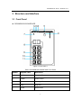
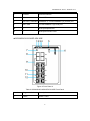
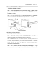
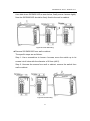
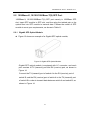
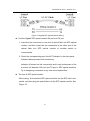
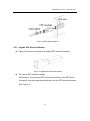
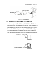
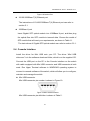
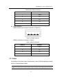
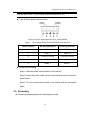
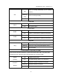
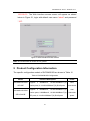
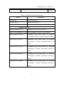
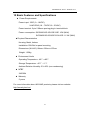
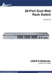
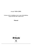
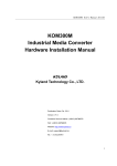
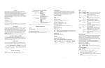
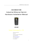
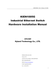
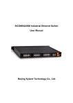
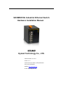
SICOM3010G Industrial Ethernet Switch Hardware Installation Manual Kyland Technology Co., LTD. Publication Date: Oct. 2011 Version: V1.0 Customer Service Hotline: (+8610) 88796676 FAX: (+8610) 88796678 Website: http://www.kyland.cn E-mail: [email protected] SICOM3010G User’s Manual-v1.0 SICOM3010G Industrial Ethernet Switch Hardware Installation Manual Disclaimer: Kyland Technology Co., Ltd. tries to keep the content of this manual as accurate and as updated as possible. This document is not guaranteed to be error-free, and we reserve the right to amend it without notice to users. Copyright © 2011 KYLAND Technology CO., LTD. All rights reserved. No part of this documentation may be excerpted, reproduced, translated, annotated or duplicated, in any form or by any means without the prior written permission of KYLAND Corporation. 1 SICOM3010G User’s Manual-v1.0 . Notice for Safety Operation This product performs reliably as long as it is used according to the guidance. Artificial damage or destruction of the equipment should be avoided. Read this manual carefully and keep it for future reference; Do not place the equipment near water sources or damp areas; Do not place anything on power cable or put the cable in unreachable places; Do not tie or wrap the cable, which may cause a fire risk; Power connectors and other equipment connectors should be firmly interconnected and checked frequently; Do not repair the equipment by yourself, unless it is clearly specified in the manual; Please keep the equipment clean; if necessary, wipe the equipment with soft cotton cloth. In the following cases, please immediately shut down your power supply and contact your Kyland representative: Water gets into the equipment; Equipment damage or shell damage; Equipment operation or performance has abnormally changed; The equipment emits odor, smoke or abnormal noise. 2 SICOM3010G User’s Manual-v1.0 Contents 1 Packing List .......................................................................................................... 4 2 Product Overview ................................................................................................. 4 3 Structure and Interface ......................................................................................... 5 3.1 Front Panel .................................................................................................... 5 3.2 Top Panel ...................................................................................................... 7 4 Mounting............................................................................................................... 8 4.1 Dimension Drawing ........................................................................................ 8 4.2 Mounting Steps .............................................................................................. 9 5 Cable Connection ............................................................................................... 12 5.1 10/100/1000Base-T(X) Ethernet Port ........................................................... 12 5.2 1000Base-X, 10/100/1000Base-T(X) SFP Port ............................................ 14 5.2.1 Gigabit SFP Optical Module .................................................................... 14 5.2.2 Gigabit SFP Electrical Module ................................................................. 16 5.3 1000Base-X, 10/100/1000Base-T(X) Combo Port........................................ 17 5.4 Console Interface ......................................................................................... 18 5.5 Power .......................................................................................................... 19 5.6 Grounding .................................................................................................... 20 5.7 Relay Contact .............................................................................................. 22 6 LED Indicators .................................................................................................... 23 7 Reset Button ....................................................................................................... 25 8 Management Access .......................................................................................... 25 8.1 Connected through Console Port ................................................................. 25 8.2 Connected through Ethernet Cable .............................................................. 28 8.3 Web Access ................................................................................................. 28 9 Product Configuration Information ...................................................................... 29 10 Basic Features and Specifications ...................................................................... 31 3 SICOM3010G User’s Manual-v1.0 1 Packing List SICOM3010G Industrial Ethernet Switch 1 CD 1 Screwdriver 1 18#AWG yellow-green line 1 Certificate of Quality (including Certificate of Compliance) 1 Note: After unpacking, please check the accessories and the appearance of the equipment. If anything is missing or damaged, please contact us. 2 Product Overview SICOM3010G is a series of green low power consumption and full Gigabit ports industrial Ethernet switch that can be applied extensively in wind power, distribution network automation, subway PIS、AFC, power SACDA, wastewater treatment, highway, metallurgy, hydroelectric power, photovoltaic power, railway CBTC, factory automation, intelligent transportation and many other industries. SICOM3010G has a Mini USB Console port, and supports Web, Telnet and Console network management; supports VCT (Virtual Cable Test); supports one-key recovery. SICOM3010G industrial Ethernet switch supports DIN-Rail and panel mounting. It provides 1000Base-X, 10/100/1000Base-T(X) Combo ports, 1000Base-X, 10/100/1000bBase-T(X) SFP ports, and 10/100/1000Base-T(X) ports. 4 SICOM3010G User’s Manual-v1.0 3 Structure and Interface 3.1 Front Panel SICOM3010G-2GX/GE-6GE Figure 1 Front Panel 1 Table 1 SICOM3010G-2GX/GE-6GE Front Panel Number Diagram Label Description 1 PWR1 Power 1 LED 2 PWR2 Power 2 LED 3 Run Running LED 4 Ring Ring LED 5 Reset Reset button 5 SICOM3010G User’s Manual-v1.0 6 Console Console interface 7 Alarm Alarm LED 8 GX7/GE7, GX8/GE8 1000Base-X, 10/100/1000Base-T(X) Combo port 9 GE1~GE6 10/100/1000Base-T(X) RJ45 port 10 -- RJ45 port Speed LED 11 -- RJ45 port Link/ACT LED SICOM3010G-2GX/GE-2GX-6GE Figure 2 Front Panel 2 Table 2 SICOM3010G-2GX/GE-2GX-6GE Front Panel Number Diagram Label Description 1 PWR1 Power 1 LED 6 SICOM3010G User’s Manual-v1.0 2 PWR2 Power 2 LED 3 Run Running LED 4 Ring Ring LED 5 Reset Reset button 6 Console Console interface 7 Alarm Alarm LED 8 GX9, GX10 1000Base-X, 10/100/1000Base-T(X) SFP port 9 GX7/GE7, GX8/GE8 1000Base-X, 10/100/1000Base-T(X) Combo port 10 GE1~GE6 10/100/1000Base-T(X) RJ45 port 11 -- RJ45 port Speed LED 12 -- RJ45 port Link/ACT LED 3.2 Top Panel 7 Figure 3 Top Panel SICOM3010G User’s Manual-v1.0 Table 3 SICOM3010G Top Panel Number Description 1 Power supply terminal block 2 Grounding Screw 3 Relay contact 4 Mounting 4.1 Dimension Drawing Dimension Drawing for DIN-Rail Mounting (Unit: mm) Figure 4 DIN-Rail Mounting Dimension Dimension Drawing for Panel Mounting (Unit: mm) 8 SICOM3010G User’s Manual-v1.0 Figure 5 Panel Mounting Dimension 4.2 Mounting Steps SICOM3010G DIN-Rail Mounting The specific steps are as follows: Step 1: Select the mounting position for SICOM3010G and ensure that there is adequate space. Step 2: Insert the top of the DIN-Rail into the slot of the DIN-Rail connecting seat in the rear panel of SICOM3010G as shown below; move the switch in the direction of arrow 2 to put the whole Din-Rail into the seat; check whether SICOM3010G is firmly mounted on the DIN-Rail, as shown below. Figure 6 DIN-Rail Mounting 9 Remove SICOM3010G from DIN-Rail SICOM3010G User’s Manual-v1.0 The specific steps are as follows: Step 1: Insert the screwdriver into the hole at the bottom of spring locking plate; press the plate down to loosen the connection of DIN-Rail and switch, as shown in arrow 1. Step 2: Pull the SICOM3010G up in the direction of arrow 2; meanwhile remove the switch from the DIN-Rail along the direction of arrow 3. Figure 7 Dismounting SICOM3010G Panel Mounting The specific steps are as follows: Step 1: Select the mounting position for SICOM3010G on the wall or in cabinet; ensure that there is adequate space for the switch. Step 2: Drill 4 holes on the selected position according to the panel mounting dimension drawing; use a cross-screwdriver to screw 4 cross-slot screws (M3×10) into holes. Don’t tighten the screws completely; leave about 5mm of space between. Step 3: Aim 4 mounting holes on SICOM3010G mounting plate at 4 fixed screws; pass the screws through 4 holes with the diameter of 6.5mm (Ф6.5); 10 SICOM3010G User’s Manual-v1.0 then slide down SICOM3010G as seen below; finally screw 4 screws tightly. Now the SICOM3010G should be firmly fixed to the wall or cabinet. Figure 8 Panel Mounting Remove SICOM3010G from wall or cabinet The specific steps are as follows: Step 1: Use a screwdriver to loosen 4 screws; move the switch up to let screws into 4 holes with the diameter of 6.5mm (Ф6.5). Step 2: Unscrew the screws from wall or cabinet; remove the switch from wall or cabinet. Figure 9 Dismounting 11 SICOM3010G User’s Manual-v1.0 5 Cable Connection 5.1 10/100/1000Base-T(X) Ethernet Port 10/100/1000Base-T(X) Ethernet RJ45 port can be connected to terminal equipment and network devices with straight-through cables or crossover cables. RJ45 connectors must be equipped at both ends of cable. Pin definition of 10/100/1000Base-T(X) RJ45 port Pin number of 10/100/1000Base-T(X) RJ45 port is shown in Figure 10. Figure 10 RJ45 Port Pin definition of 10/100/1000Base-T(X) RJ45 port is shown in Table 4. Table 4 Pin Definition of 10/100/1000Base-T(X) RJ45 Port Pin MDI MDI-X 1 Transmit/Receive Data(TRD0+) Transmit/Receive Data(TRD1+) 2 Transmit/Receive Data(TRD0-) Transmit/Receive Data(TRD1-) 3 Transmit/Receive Data(TRD1+) Transmit/Receive Data(TRD0+) 4 Transmit/Receive Data(TRD2+) Transmit/Receive Data(TRD3+) 5 Transmit/Receive Data(TRD2-) Transmit/Receive Data(TRD3-) 6 Transmit/Receive Data(TRD1-) Transmit/Receive Data(TRD0-) 7 Transmit/Receive Data(TRD3+) Transmit/Receive Data(TRD2+) 12 SICOM3010G User’s Manual-v1.0 8 Transmit/Receive Data(TRD3-) Transmit/Receive Data(TRD2-) Note: “+”“-”means level polarity. Wiring Sequence Figure 11 10/100/1000M Straight-through Cable Wiring Figure 12 10/100/1000M Cross-over Cable Wiring Note: The correlation between the pin of RJ45 connector and the color of twisted pair is: 1-orange and white, 2-orange, 3-green and white, 4-blue, 5-blue and white, 6-green, 7-brown and white, 8-white. 13 SICOM3010G User’s Manual-v1.0 5.2 1000Base-X, 10/100/1000Base-T(X) SFP Port 1000Base-X, 10/100/1000Base-T(X) SFP port namely is 1000Base SFP slot. Insert SFP module to SFP slot, and then plug the twisted pair or the optical fiber into SFP module to transmit data. Choose the model of SFP module to meet your requirements, as shown in Table 11. 5.2.1 Gigabit SFP Optical Module Figure 13 shows an example of a Gigabit SFP optical module; Figure 13 Gigabit SFP Optical Module Gigabit SFP optical module is equipped with LC connector, and each port consists of TX (transmit) port and RX (receive) port, as shown in Figure 14. Connect the TX (transmit) port of switch A to the RX (receive) port of switch B, and the RX (receive) port of switch A to the TX (transmit) port of switch B in order to transmit data between switch A and switch B, as shown in Figure 14. 14 SICOM3010G User’s Manual-v1.0 Figure 14 Gigabit SFP Optical Module Wiring Confirm Gigabit SFP optical module RX port and TX port 1. Insert the two connectors in one end of optical fiber into SFP optical module, and then insert the two connectors in the other end of the optical fiber into SFP optical module of another switch to communicate. 2. Check the corresponding port Link/ACT indicator in the front panel: Indicator flashing means link connectivity; Indicator off means no link connectivity and it may be because of the incorrect link between RX port and TX port in SFP optical modules. Try to swapping connectors in any one end of optical fiber. The use of SFP optical module While wiring, first insert the SFP optical module into the SFP slot in the switch, and then plug the optical fiber into the SFP optical module. See Figure 15. 15 SICOM3010G User’s Manual-v1.0 Figure 15 SFP Optical Module 5.2.2 Gigabit SFP Electrical Module Figure 16 shows an example of a Gigabit SFP electrical module; Figure 16 Gigabit SFP Electrical Module The use of SFP electrical module While wiring, first insert the SFP electrical module into the SFP slot in the switch, and then plug the twisted pair into the SFP electrical module. See Figure 17. 16 SICOM3010G User’s Manual-v1.0 Figure 17 SFP Electrical Module 5.3 1000Base-X, 10/100/1000Base-T(X) Combo Port As shown in Figure 18, The 1000Base-X, 10/100/1000Base-T(X) Combo port consists of one 1000 Base-X port (GX7) and one 10/100/1000Base-T(X) Ethernet port (GE7), and only one of the two ports can be used at one time. Besides, the 1000 Base-X port has priority over 10/100/1000Base-T(X) port. Plug the optical fiber and the twisted pair into GX7 and GE7 respectively; GX7 can communicate normally and the GE7 will be disabled automatically. 17 SICOM3010G User’s Manual-v1.0 Figure 18 Combo Port 10/100/1000Base-T(X) Ethernet port The instructions of 10/100/1000Base-T(X) Ethernet port can refer to section 5.1. 1000Base-X port Insert Gigabit SFP optical module into 1000Base-X port, and then plug the optical fiber into SFP module to transmit data. Choose the model of SFP module that will meet your requirements, as shown in Table 11. The instructions of Gigabit SFP optical module can refer to section 5.2.1. 5.4 Console Interface Install the driver for Mini USB onto your PC. The driver “Mini USB driver.exe” is in the software download folder, which is on the supplied CD. Connect the USB port on the PC to the Console interface on the switch with cable equipped with Mini USB connector and USB connector at both ends. Run Hyper Terminal software in WINDOWS operating system to connect to console software of the switch, which will allow you to configure, maintain and manage the switch. Mini USB connector Mini USB connector pin number is shown in Figure 19. Figure 19 Mini USB Connector Mini USB connector pin definition is shown in Table 5. 18 SICOM3010G User’s Manual-v1.0 Table 5 Mini USB Pin Definition Mini USB Pin Definition 1 VBUS 2 D- 3 D+ 4 ID 5 GND USB connector USB connector pin number is shown in Figure 20. Figure 20 USB Connector USB pin definition is shown in Table 6. Table 6 USB Pin Definition USB Pin Definition 1 VBUS 2 D- 3 D+ 4 GND 5.5 Power According to the power input requirements, use a 5.08mm-spacing terminal block to connect power cable. Note: The cross section area of power cable is required to be greater than 0.75mm2 19 SICOM3010G User’s Manual-v1.0 and less than 2.5mm2. The grounding resistance requirement: <5Ω. 5 pin 5.08mm power terminal block Figure 21 5-pin 5.08mm-spacing Plug-in Terminal Block Table 7 5 Pin 5.08mm Power Terminal Block Contact Definition Contact Number DC Wiring Definition AC Wiring Definition 1 PWR1: + PWR1: L 2 PWR1: - PWR1: N 3 Protection Ground Protection Ground 4 PWR2: - PWR2: N 5 PWR2: + PWR2: L Wiring and mounting Step 1: Take the power terminal block off the switch. Step 2: Insert the power cable into the terminal block and connect the power cable. Step 3: Put the terminal block back to the switch with the connected cable. 5.6 Grounding Chassis grounding and power terminal grounding 20 SICOM3010G User’s Manual-v1.0 Figure 22 Chassis Grounding and Power Terminal Grounding There is a grounding screw on the top panel of the SICOM3010G, which is for chassis ground. One end of the chassis grounding cable is connected with the grounding screw and the other end of the cable is reliably grounded. (The cross section area of chassis grounding cable should be more than 2.5mm2. The grounding resistance requirement: <5Ω) The grounding part in the 5.08mm power terminal block is called protection ground. It is required to connect the chassis grounding part with the protection grounding part with supplied 18#AWG yellow-green line to allow the switch to operate safely and precisely. The dimension drawing of 18#AWG yellow-green line is shown in Figure 23. 21 SICOM3010G User’s Manual-v1.0 Figure 23 18#AWG Yellow-Green Line (Unit: mm) Note: If SICOM3010G needs to perform a dielectric voltage withstand test, in order to avoid test failure, please disconnect the 18#AWG yellow-green line to disable surge protection circuit that leads to leakage electricity. Figure 24 Disconnect 18#AWG Yellow-Green Line (Unit: mm) 5.7 Relay Contact The relay contact is used for alarm output. When the switch works normally, the normally-open contact of the alarm relay is closed and the normally-closed contact is open; when the alarm occurs, the normally-open contact is open and the normally-closed contact is closed. The alarm is outputted through a 3-pin 5.08mm spacing terminal block as shown in 22 SICOM3010G User’s Manual-v1.0 Figure 25. Figure 25 3-Pin 5.08mm-Spacing Plug-In Terminal Blocks The electrical parameters of the relay: Max Switch Voltage: 250VAC/220VDC; Max Switch Current: 2A Max Switch Power: 60W Note: Pin 1 and pin 2 are normally-open contacts; pin 2 and pin 3 are normally-closed contacts. When the switch works normally, the pin 1 and 2 are closed, pin 2 and pin 3 are open; when the alarm occurs, the pin 1 and 2 are open; pin 2 and 3 are closed. Wiring and mounting Step 1: Take the alarm terminal block off the switch. Step 2: Insert the cable for alarm output into the alarm terminal block according to the requirements and connect the cable. Step 3: Put the alarm terminal block back to the switch with the connected cable. 6 LED Indicators Table 8 Front Panel LED LED State Description Running LED 23 SICOM3010G User’s Manual-v1.0 CPU is running abnormally or the switch is ON starting. Run Blinking CPU is running normally (1HZ) OFF CPU is not started up. Alarm LED ON System alarm OFF No system alarm. Alarm Power LEDs ON Power 1 connects and operates normally. OFF Power 1 disconnects or operates abnormally. ON Power 2 connects and operates normally. OFF Power 2 disconnects or operates abnormally. PWR1 PWR2 Ring LED Ring ON Master (DT-Ring mode)/Root(DRP mode) Blinking Slave (DT-Ring mode)/B-Root(DRP mode) OFF No ring mode 10/100/1000Base-T(X) RJ45 port LEDs Each RJ45 port has two indicators, a yellow LED and a green LED. The yellow LED indicates port rate, while the green LED indicates port connection state. Speed ON 1000M working state (Yellow) OFF 10/100M working state or no connection ON Effective network connection in the port Link/ACT Blinking Network activities in the port (Green) OFF No effective network connection in the port 24 SICOM3010G User’s Manual-v1.0 7 Reset Button Reset button supports reboot and restoring default configuration. Push the reset button and hold for one second then release to reboot the switch. Hold the reset button down for five seconds then release to restore default configuration (including IP address) and reboot; the default IP address is 192.168.0.2. Note: Don’t hold the reset button down for more than 5 second to avoid restoring default configuration. 8 Management Access Access the switch by one of the following three ways. 8.1 Connected through Console Port 1. Install the driver for Mini USB onto your PC. The driver “Mini USB driver.exe” is in the software download folder, which is on the supplied CD. 2. Use the Console cable that is equipped with Mini USB connector at one end and USB connector at the other end to connect the Console interface on the switch with the USB port on PC. 3. On Windows desktop, click Start → All programs → Accessories → Communications → Hyper Terminal. 25 SICOM3010G User’s Manual-v1.0 Figure 26 Hyper Terminal 4. Build a new connection named “aa” Figure 27 New Connection 5. Select COM port as the connection type. 26 SICOM3010G User’s Manual-v1.0 Figure 28 Choose Port 6. Set the parameters of COM port (Bits per second: 115200, Data bits: 8, Parity: None, Stop bits: 1, Flow control: None) Figure 29 Set COM Parameters 7. Click “OK” to enter the CLI interface, and type in a CLI command from Table 9. Table 9 CLI Command View Command Description User View SWITCH>enable Enter management view Management View SWITCH#show interface 27 Show the IP address of current switch Management View SWITCH#show version Management View SWITCH#reboot Management View SWITCH#load default SICOM3010G User’s Manual-v1.0 Show version of switch Reboot Restore default configuration (except for IP address) Management View SWITCH#config terminal Enter configuration view 8.2 Connected through Ethernet Cable 1. Connect any RJ45 port of the switch with the Ethernet port of a personal computer with a RJ45 cable. 2. Open Run window from the start menu, then input “telnet + ‘IP address’”. The default IP address is 192.168.0.2. Figure 30 Enter Telnet 3. Click “OK” to enter the Telnet configuration interface. Type in a CLI command from Table 9. 8.3 Web Access 1. Connect the Ethernet port on the PC to any RJ45 port on the switch. 2. Input the IP address of the current switch in web browser, the default IP is 28 SICOM3010G User’s Manual-v1.0 192.168.0.2. The Web interface access screen will appear as shown below in Figure 31, login with default user name “admin” and password “123”. Figure 31 Web Interface Access Screen Note: We recommend IE version 8.0 or greater. 9 Product Configuration Information The specific configuration models of SICOM3010G are shown in Table 10 Table 10 SICOM3010G Configuration Model Interface Description Power SICOM3010G-2GX/ supports 2 1000Base-X, 10/100/1000Base-T(X) 12DC, GE-6GE Combo ports; 6 10/100/1000Base-T(X) RJ45 ports 24AC/DCW supports 2 1000Base-X, 10/100/1000Base-T(X) dual Combo ports; 21000Base-X, 10/100/1000Base-T(X) redundant SICOM3010G-2GX/ GE-2GX-6GE SFP ports; 6 10/100/1000Base-T(X) RJ45 ports 29 power SICOM3010G User’s Manual-v1.0 inputs Table 11 SICOM3010G Optional Accessories Model Description DT-BGAZ-02 Panel mounting kit DT-FCZ-RJ45-01 RJ45 dustproof shield DT-XL-Mini USB-USB-2m USB console cable, Mini USB to USB, 2m Gigabit SFP Module IGSFP-1000BASE-T-RJ45 1000Base-T(X) port, RJ45 connector IGSFP-10/100/1000BASE-T-RJ45 10/100/1000Base-T(X) port, RJ45 connector IGSFP-M-SX-LC-850-0.55 1000Base-X port; multi mode, LC connector; wavelength is 850nm, transmission distance is 550m IGSFP-S-LX-LC-1310-10 1000Base-X port; single mode, LC connector; wavelength is 1310nm, transmission distance is 10Km IGSFP-S-LH-LC-1310-40 1000Base-X port; single mode, LC connector; wavelength is 1310nm, transmission distance is 40Km IGSFP-S-ZX-LC-1550-60 1000Base-X port; single mode, LC connector; wavelength is 1550nm, transmission distance is 60Km IGSFP-S-ZX-LC-1550-80 1000Base-X port; single mode, LC connector; wavelength is 1550nm, transmission distance is 80Km 30 SICOM3010G User’s Manual-v1.0 10 Basic Features and Specifications Power Requirements Power input: 12DC (9~18VDC), 24AC/DCW (18~72VDC,18~50VAC) Power terminal: 5-pin 5.08mm-spacing plug-in terminal block Power consumption: SICOM3010G-2GX/GE-6GE: 10W (MAX) SICOM3010G-2GX/GE-2GX-6GE: 11.3W (MAX) Physical Characteristics Housing: Metal, fanless Installation: DIN-Rail or panel mounting Dimensions (W×H×D): 88mm×135mm×137mm Weight: 1.25Kg Environment Limits Operating Temperature: -40℃~+85℃ Storage Temperature: -40℃~+85℃ Ambient Relative Humidity: 5%~95% (non-condensing) MTBF 345000h Warranty 5 years For more information about KYLAND products, please visit our website: http://www.kyland.cn/ 31