1
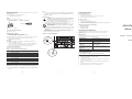
DECLARATION OF CONFORMITY NOTICE Enterasys Networks and its licensors reserve the right to make changes in specifications and other information contained in this document without prior notice. The reader should in all cases consult Enterasys Networks to determine whether any such changes have been made. The hardware, firmware, or software described in this manual is subject to change without notice. IN NO EVENT SHALL ENTERASYS NETWORKS AND ITS LICENSORS BE LIABLE FOR ANY INCIDENTAL, INDIRECT, SPECIAL, OR CONSEQUENTIAL DAMAGES WHATSOEVER (INCLUDING BUT NOT LIMITED TO LOST PROFITS) ARISING OUT OF OR RELATED TO THIS MANUAL OR THE INFORMATION CONTAINED IN IT, EVEN IF ENTERASYS NETWORKS AND ITS LICENSORS HAVE BEEN ADVISED OF, KNOWN, OR SHOULD HAVE KNOWN, THE POSSIBILITY OF SUCH DAMAGES. Enterasys Networks, Inc. 35 Industrial Way Rochester, NH 03866-5005 Application of Council Directive(s): Manufacturer’s Name: Manufacturer’s Address: European Representative Address: Conformance to Directive(s)/ Product Standards: 2001 by Enterasys Networks, Inc. All Rights Reserved Printed in the United States of America Equipment Type/Environment: Order Number: 9033769 December 2001 X-Pedition and Enterasys Networks are registered trademarks of Enterasys Networks or its licensors. All other product names mentioned in this manual may be trademarks or registered trademarks of their respective companies. INDUSTRY CANADA NOTICE This digital apparatus does not exceed the class A limits for radio noise emissions from digital apparatus set out in the Radio Interference Regulations of the Canadian Department of Communications. Le présent appareil numérique n’émet pas de bruits radioélectriques dépassant les limites applicables aux appareils numériques de la class A prescrites dans le Règlement sur le brouillage radioélectrique édicté par le ministère des Communications du Canada. VCCI NOTICE This is a class A product based on the standard of the Voluntary Control Council for Interference by Information Technology Equipment (VCCI). If this equipment is used in a domestic environment, radio disturbance may arise. When such trouble occurs, the user may be required to take corrective actions. LEDs The SSR-GTX32-04 is a copper-based 1000Base-T Gigabit Ethernet module for the Enterasys X-Pedition platform. The SSR-GTX32-04 provides four ports of 1000Base-T switched and routed connectivity through Category 5 RJ45 connectors and is ideal for high-speed collapsed backbones and server-farm connections. The SSR-GTX32-04 delivers full-function Layer-2, Layer-3, and Layer-4 switching and routing. Table 2 Enterasys Networks Ltd. Nexus House, Newbury Business Park London Road, Newbury Berkshire RG14 2PZ, England EC Directive 89/336/EEC EC Directive 73/23/EEC EN 55022 EN 55024 EN 60950 EN 60825 Networking Equipment, for use in a Commercial or Light Industrial Environment. AGENCY STANDARDS LED Indicators LED Condition Status Online On (Green) The module is online and ready to receive, process, and send packets (if configured to do so). SPECIFICATIONS Offline On (Amber) The module is offline (powered down) and ready to hotswap. Ports Per-Port Transmit Green The port transmitted a packet. The OCMAC controls this LED. Orange The port transmitted a flow-control packet. The OCMAC controls this LED. Green The port received a packet. The OCMAC controls this LED. Orange The port received a flow-control packet. The OCMAC controls this LED. 4 1000Base-T Ports Enterasys Networks, Inc. declares that the equipment packaged with this notice conforms to the above directives. FCC NOTICE This device complies with Part 15 of the FCC rules. Operation is subject to the following two conditions: (1) this device may not cause harmful interference, and (2) this device must accept any interference received, including interference that may cause undesired operation. NOTE: This equipment has been tested and found to comply with the limits for a class A digital device, pursuant to Part 15 of the FCC rules. These limits are designed to provide reasonable protection against harmful interference when the equipment is operated in a commercial environment. This equipment uses, generates, and can radiate radio frequency energy and if not installed in accordance with the operator’s manual, may cause harmful interference to radio communications. Operation of this equipment in a residential area is likely to cause interference in which case the user will be required to correct the interference at his own expense. WARNING: Changes or modifications made to this device which are not expressly approved by the party responsible for compliance could void the user’s authority to operate the equipment. SSR-GTX32-04 89/336/EEC 73/23/EEC Enterasys Networks, Inc. 35 Industrial Way PO Box 5005 Rochester, NH 03867 Network Interface RJ-45 100m Cat5 UTP Cabling per ANSI/TIA/EIA-568-A Per-Port Receive Number of Flows/Routes Layer-2 Entries =512,000 (memory size = 32 MB) Layer-3 Entries = 256,000 (memory size = 16 MB) Per-Port Link Green Physical Dimensions Size: 27.94 cm H x 3.94 W x 19.68 D (11.00 in. H x 1.55 W x 7.75 D) Weight 1.4 kg (3.0 lbs) Safety Power Consumption Meets the requirements of UL 1950, CSA 22.2 No. 950, 73/23/EEC, EN 60825, EN 60950, and IEC 950. BTU/hr = 258.21 AC Volt Amps = 75.68 Per-Port Quality NOTE: If your system uses a redundant power configuration or only one power supply, you will not be able to support more than 5 cards in the XP-8000 and 10 in the XP-8600. Electromagnetic Compatibility Compliant with the requirements of FCC Part 15, CSA C108.8, 89/336/EEC, EN 55022, EN 61000-3-2, EN 61000-3-3, EN 55024, AS/NZS 3548, and VCCI V-3. Off No link exists from the port. Green Autonegotiation completed successfully and the phy is attempting to establish a link. This LED remains green while the link operates with good signal-to-noise ratio. Fast blink Low signal-to-noise ratio, close to data errors. Slow blink Receive bit errors detected. Off Autonegotiation is in progress or the phy cannot receive packet data. Temperature Operating: 41° to 104° F (5° to 40° C) Storage: -22° to 164° F (-30° to 73° C) Options Available Humidity 15% to 90% (non-condensing) CONNECTIVITY GUIDELINES Table 1 The port hardware detected a cable plugged into the port and established a good link. Recommended Cable Types and Specifications Cable Type Max. Length Connector 1000Base-T Cat. 5 100-ohm UTP 100 m (328 ft) RJ-45 The SSR-GTX32-04 provides switching and routing on hardware, thereby eliminating the performance bottleneck caused by a single processor. The module supports application switching (i.e., Network Address Translation, Server Load Balancing, Per-Flow Rate Limiting, Access Control Lists, and full RMON/RMON 2) and extra features like the Local Hardware Routing Table, Port Rate Limiting, Aggregate Rate Limiting, and Jumbo Frames that are essential for Application Service Providers, Multi-Dwelling Unit (MDU) Service Providers, and Large Enterprise Networks. The SSR-GTX32-04 offers ten times the bandwidth available through the existing Category 5 infrastructure and interoperates with all existing X-Pedition Router modules. This allows network managers to leverage their existing cabling infrastructure and equipment without an extensive upgrade. INSTALLING THE MODULE ELECTRICAL HAZARD: Only qualified personnel should perform installation procedures. Handling the Module CAUTION: The SSR-GTX32-04 is easily damaged by electrostatic discharge. To prevent electrostatic damage, observe the following guidelines: Do not remove the module from its packaging until you are ready to install it. Do not touch any of the module’s pins, connectors or components. Hold the module only by its edges or front panel. Wear an anti-static wristband connected to a suitable earth ground whenever handling the module. Store or transport this module only in appropriate anti-static packaging. CLASS A ITE NOTICE • • • • • WARNING: This is a class A product. In a domestic environment this product may cause radio interference in which case the user may be required to take adequate measures. 1 2 Equipment Checklist TROUBLESHOOTING OR... After unpacking the SSR-GTX32-04, check the contents of the box to be sure you received the following items: One SSR-GTX32-04 module in anti-static bag One disposable anti-static wristband • • • • Enter the following from the CLI and click enter: Enable -> System -> Hotswap -> Out -> Slot -> #. The Online LED will turn off and the Offline LED will turn on. Remove the module. Instructions Tools CAUTION: You may install the SSR-GTX32-04 in the chassis with the chassis powered up. However, before removing an existing line card, hotswap the line card as described previously. This installation requires the following tools: Anti-static wristband Phillips screwdriver 1. 2. If a cover plate is installed in the line module slot, remove the cover plate: loosen the captive screws on each side of the coverplate and pull out the plate. Align the backsheet of the line card between the card guides as shown in Figure 1. NOTE: Make sure that the circuit card is between the card guides. Check both tracks. 3. Preliminary Setup 4. Firmware Image Requirements Version 9.0.0.0 or later. 5. Default Module Settings The default mode for each port on the XP-8000 and XP-8600 is: Full duplex/ 1000 mbs/ autonegotiation on To view the current mode for a particular port, enter the following (where x is the chassis slot that contains the line card and y is a specific port number on the card): XP# port show port status gi.x.y Slide the line card all the way into the slot, firmly but gently pressing the line card fully in place to ensure that the pins on the back of the line card are completely seated in the backplane. Tighten captive screws. Align the captive screws with the holes in the face of the module and tighten the screws to secure the SSR-GTX32-04 to the chassis. Repeat the above steps for additional cards. Card Guides Circuit Card SSR-CM2 Console Metal Plate RJ45 Connector Pin Assignments Tx TRD0 + Diff Output 2 TRD0 - Diff Output 3 TRD1 + Diff Output 4 TRD2 + Diff Output 5 TRD2 - Diff Output 6 TRD1 - Diff Output 7 TRD3 + Diff Output 8 TRD3 - Diff Output • • • The XP is not powered up. The module is not properly seated in the slot. Connectors on both ends of the cable are not properly engaged. The copper cable did not click into place or is not properly seated. Helpful CLI Commands for Debugging • • • System show hardware System show version System show bootlog ADDITIONAL INFORMATION OFFLINE Link ONLINE Quality CONTROL MODULE 10/100 Mgmt World Wide Web http://www.enterasys.com/ Phone (603) 332-9400 Internet mail [email protected] FTP Login Password ftp://ftp.enterasys.com anonymous your email address To acquire the latest image for this product and any available release notes http://www.enterasys.com/download Additional documentation http://www.enterasys.com/support/manuals Before contacting Enterasys Networks for technical support, have the following information ready: • • • • • • Hotswap Your Enterasys Networks service contract number A description of the failure A description of any action(s) taken to resolve the problem (e.g., changing mode switches, rebooting the unit) The serial and revision numbers of all involved Enterasys Networks products in the network A description of your network environment (layout, cable type, etc.) Network load and frame size at the time of trouble (if known) You may install this module into a live system without powering off the device. However, do not remove an active module from a live system except under the following conditions: • Press the Hotswap button. The Online LED will turn off and the Offline LED will turn on. 3 SSR-GTX32-04 Quick Start For additional information about installing this module or to learn more about what capabilities are included in the firmware release you are using, visit the Enterasys Networks web site. To send comments or suggestions concerning this document, contact the Technical Writing Department via the following email address: [email protected] Please include the document Part Number in the email message. Rx Connection 1 Common Errors For additional support related to the Common CLI syntax or this document, contact Enterasys Networks using one of the following methods: The connector pins are assigned as follows: Pin Offline LED lights at power-up. Port LEDs flicker briefly during system boot while ports initialize. Online LED turns on once module is active. Getting Help Connector Pin Assignments Table 3 • • • Figure 1 Install the Module CLI Setup Enter the following commands at the CLI before implementing any configurations. 1. Enable —> Configure —> <Enter>. 2. Once you reach the configuration prompt, you can configure the SSR-GTX32-04 using CLI commands as described in the X-Pedition CLI manual. Enter the ? character to view the options available to you in configuration mode. Proper Boot Sequence 4 5 Web Site: http://www.enterasys.com/ 9033769