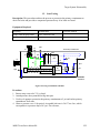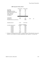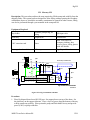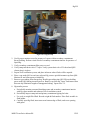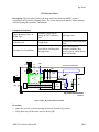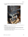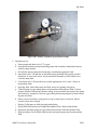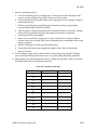
1
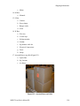
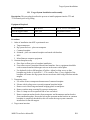
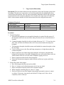
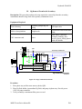
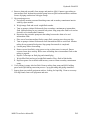
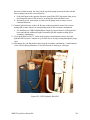
Report No. 203-HJT-9012 R0
MERIT Target System
Installation Manual
Adam J. Carroll
Van B. Graves
Philip T. Spampinato
March 2007
Introduction
MERIT Target System Installation Manual
Adam J. Carroll
Van B. Graves
Philip T. Spampinato
DISCLAIMER
This report was prepared as an account of work sponsored by an agency of the United States Government.
Neither the United States government nor any agency thereof, nor any of their employees, makes any warranty,
express or implied, or assumes any legal liability or responsibility for the accuracy, completeness, or usefulness of
any information, apparatus, product, or process disclosed, or represents that its use would not infringe privately
owned rights. Reference herein to any specific commercial product, process, or service by trade name,
trademark, manufacturer, or otherwise, does not necessarily constitute or imply its endorsement,
recommendation, or favoring by the United States Government or any agency thereof. The views and opinions of
authors expressed herein do not necessarily state or reflect those of the United States Government or any agency
thereof.
Oak Ridge National Laboratory is managed by UT-Battelle, LLC, under contract DE-AC05-00OR22725 for the
U.S. Department of Energy.
MERIT Installation ManualR0
i
Introduction
Table of Contents
I.
Introduction ................................................................................................................. I-1
II.
Shipping Information.................................................................................................. II-1
III.
Target System Installation and Assembly .................................................................III-1
IV.
Removing Experiment from Beamline..................................................................... IV-1
V.
Target System Disassembly .......................................................................................V-1
VI.
Leak Testing ............................................................................................................. VI-3
VII.
Mercury Fill............................................................................................................. VII-1
VIII.
Mercury Drain ........................................................................................................VIII-1
IX.
Hg Removal From Inside Secondary ....................................................................... IX-1
X.
Hydraulic Fluid Fill ....................................................................................................X-1
XI.
Hydraulic Fluid Drain............................................................................................... XI-1
XII.
Hg Vapor Filter Replacement.................................................................................. XII-1
XIII.
Nozzle Replacement ...............................................................................................XIII-1
XIV. Evacuating Secondary Containment.......................................................................XIV-1
XV.
Opening Secondary Containment............................................................................XV-2
MERIT Installation ManualR0
ii
Introduction
I.
Introduction
The Mercury Intense Target (MERIT) experiment is a proof-of-principle experiment for a
Neutrino Factory or Muon Collider. MERIT creates a free-jet mercury stream that interacts
with a high-energy proton beam inside a 15 Tesla magnetic field. The experiment will be
conducted at CERN during the summer of 2007 and will utilize the TT2 and TT2A tunnels.
The MERIT Hg target system creates the desired jet with a syringe pump: two six-inchdiameter hydraulic cylinders actuate a ten-inch diameter Hg cylinder. The syringe pump and
the magnet will be located in the TT2A tunnel. The syringe cylinders are driven with a
Hydraulic Power Unit (HPU) that will be located in TT2. Operational testing of the complete
target system in a no-field condition will be conducted at Oak Ridge National Laboratory
(ORNL); water tests of the system will be followed by a mercury test. Integrated systems
testing of the Hg system and the solenoid will occur at the Massachusetts Institute of
Technology (MIT).
Upon successful completion of MIT testing, MERIT will be drained of mercury and hydraulic
fluid then disassembled. The MERIT pieces will be placed in a land-sea container for
transportation to CERN for the experiment. At CERN in the TT2A tunnel the MERIT will be
reassembled and properly commissioned as described by this document before beginning the
one-month of testing. Upon completion of experimentation the MERIT will be held in the
TT2A tunnel for a significant radioactive cool down period. The MERIT then will be
decommissioned, disassembled, and sent by the land-sea container to Oak Ridge National
Laboratory for final storage.
This document contains instructions and procedures required for all non-operational aspects
of the MERIT equipment, such as setup and disassembly, leak-checking, Hg fill and drain,
etc. These instructions should cover all expected preparatory operations required to conduct
tests at both MIT and CERN. It does not cover detailed operation of the equipment; those
procedures are provided in a separate Operations Manual.
MERIT Installation ManualR0
I-1
Shipping Information
II.
Shipping Information
Description: This section lists the location of equipment inside the shipping containers and
boxes and provides a procedure for unloading the equipment from the crates.
Packaging Arrangement
1. Wood Crate, Dimensions: 176”L x 66”W 90”H: (Figure II.1)
a. Mercury Syringe Unit
b. Three drums
c. Acrylic sought cover
Figure II.1: Wood Crate
2. Wood Crate, Dimensions: 136”L x 66”W 74”H: (Figure II.2):
a. HPU
b. Extra pallets
c. hydraulic fluid drum
d. Hg waste drum
e. Aluminum brace
MERIT Installation ManualR0
II-1
Shipping Information
Figure II.2: Wood Crate
3. Arizona Instruments Box
a. Jerome monitor and equipment
4. Both Black Plastic Box
a. Socket set
b. Tool box (screw drivers)
c. Tool box (wrench)
d. Electrical umbilical
e. Tool kits
f. Peristaltic pump
g. Power extension cords
h. Scavenger air vent
5. B Box (Black B)
a. Lab Coats
b. Gloves
c. Large cheese cloth
MERIT Installation ManualR0
II-2
Shipping Information
d. Clean up protection
6. B Box (Red B): STARTER BOX
a. RJ-45 cables
b. Air hose
c. Cables
d. Networking box
7. C Box
a. Cheese Cloth
b. Empty bottles
c. Buckets (gallon size)
8. E Box
a. VM-3000
b. Cables
9. F Box
a. Fasteners
b. Washers
10. G Box
a. Hg clean up
b. Ziploc bags
c. HgX
d. Hand held Hg vacuum pump
e. Sponges
f. Work gloves
g. Duct tape
11. H Box
a. Blue air hose
b. Hg Monitor kit
c. Replacement cables
12. J Box
a. Jerome
13. L Box
a. Tape
b. Lockout boxes
MERIT Installation ManualR0
II-3
Shipping Information
c. Shims
14. M Box
a. Manuals
15. S Box
a. Gaskets
b. Hose clamps
c. Bungee cords
d. Scale
16. W Box
a. Wire ties
b. Yellow tape
c. Helium monitor
d. Sealant
e. Hg monitor cable kit
f. Electrical Connections
g. Fuses
h. Straps
17. Assorted Boxes on pallet (Figure II.3)
a. Optics Box
b. Hg Vacuum
c. Air Hoses
Figure II.3: Assorted Boxes on Pallet
MERIT Installation ManualR0
II-4
Shipping Information
Description: This instruction outlines continues the shipping information with the unloading
operation.
Equipment Required:
Electric screw driver
Impact Wrench
Forklift with 6T capacity
Rollers and jacks
Procedure:
1. Open the two black plastic boxes and remove tool boxes.
2. Open the wood crates
a. Unscrew top panel and remove
b. Unscrew front panel and remove, hold panel while unscrewing for safety
3. Repeat step two for all creates
4. Remove smaller boxes and materials around the larger equipment.
5. Remove large hex screws to release large equipment like HPU.
6. Using a 6T capacity forklift remove pallets containing drums and boxes
7. Using a 6T capacity forklift remove large equipment
MERIT Installation ManualR0
II-5
Target System Installation
III. Target System Installation and Assembly
Description: This procedure describes the process to install equipment into the TT2 and
TT2A tunnels prior to Hg filling.
Equipment Required:
½” drive ratchet
Hex drivers
1-1/8, 1-1/4, 1-5/8 sockets
Jacks & support stands
Bottle jack
Adjustable wrench
Procedure:
1. Order of installation into MIT experimental area:
a. Target transporter
b. Hg system and cart – place on transporter
c. Common baseplate
d. Solenoid – place on common baseplate and attach with brackets
e. HPU
f. Miscellaneous computer equipment
2. Common baseplate setup
a. Place liner on floor prior to baseplate installation.
b. User rollers to move baseplate/solenoid into beamline. Survey equipment should be
used to ensure beamline and magnet axis are in the same vertical plane.
c. Use hydraulic jacks to lift baseplate off rollers. Adjust leveling screws so that
baseplate top surface is leveled 26.5 – 27.0 cm above floor. A very slight tilt of the
baseplate will ensure the Hg system does not accelerate while being rolled towards the
magnet.
3. Transporter setup
a. Use rollers to move transporter downstream of common baseplate.
b. Elevate with leveling screws to match common baseplate height.
c. Remove swivel hoist rings and attach bridging plates to transporter.
d. Remove ratchet straps securing Hg system to transporter.
e. Place C-clamp on rail on upstream side of one cart wheel.
f. Remove upstream anchor bracket from transporter and downstream anchor bracket
from common baseplate. Ensure the bolt on the upstream anchor bracket on common
baseplate is completely threaded in; this will ensure the target system cannot be
inserted too far into the magnet.
4. Target snout insertion
MERIT Installation ManualR0
III-1
Target System Installation
a. Use the turnbuckles on the secondary box to approximately align the target snout with
the magnet bore.
b. Remove C-clamp from rail.
c. Slowly roll Hg system towards magnet and adjust turnbuckles as needed. Note that if
magnet is not on the common baseplate as the cart wheels transfer from one rail to the
other, baseplate tipping can occur.
d. Once the snout support brace reaches the magnet, stop Hg system and install C-clamp
on rail.
e. Remove snout support and place pipe stand under snout. Reinstall support brace bolts
in their threaded holes.
f. Remove C-clamp and continue rolling Hg system and pipe stand towards magnet. As
the snout is more fully inserted into the magnet bore, the pipe stand can be removed.
Continue rolling until cart contact upstream anchor bolt. Place C-clamp behind cart
wheel.
g. Perform final precision insertion by adjusting upstream anchor bolt.
h. Install downstream anchor bolt and lock cart in place. Remove C-clamp.
5. Tilt & elevate common baseplate. In these steps directional references are made while
facing from the downstream end to the upstream end.
a. Attach baseplate jacking brackets using hex driver and ratchet. Torque bolts
sufficiently.
b. Place curved plates on top of jacks and position jacks under brackets. Jack stands are
labeled for each location. Attach manual hydraulic pumps to jacks.
c. Use jacks to raise baseplate off rollers. Remove rollers.
d. Adjust upstream leveling feet such that approximately 15.8 cm protrudes above gusset
plate. Adjust downstream leveling screws such that approximately 8.8 cm protrudes
above gusset plate. Adjust middle leveling screws to approximately match the
downstream screws.
e. Use jacks to raise entire baseplate high enough to insert magnet support beam under
upstream leveling feet. Baseplate does not have to be perfectly level during this
process, as the downstream end will be lowered. Insert support beam under upstream
feet, centering pads under circular feet.
f. Ensure clearance between upstream leveling feet and support beam and relieve
pressure from upstream jacks to allow baseplate to lower onto support beam. Do not
remove jacks yet.
g. Ensure clearance between downstream leveling feet and floor. Relieve pressure from
downstream jacks to allow baseplate to lower until jacks bottom out.
h. Insert bottle jack under downstream end of baseplate, centered between the sides.
i. Raise downstream end of baseplate with bottle jack to allow side jacks to be removed.
j. Relieve pressure from bottle jack to allow downstream leveling screws to rest on floor.
k. Final elevation of downstream end of baseplate is approximately 20.1 cm above floor;
upstream corner of baseplate is approximately 37.1 cm above floor. Height
adjustments are made using the leveling screws. While it is preferred that the baseplate
MERIT Installation ManualR0
III-2
Target System Installation
weight be taken off the screws prior to adjustment, minor height adjustments (<2mm)
can be made by turning a screw under load.
l. The middle leveling screws should be adjusted so they are snug against the floor.
6. Final alignment
a. Final alignment adjustments are made using surveying equipment or beam
information.
b. Lateral positioning adjustments can be made by loosening the tie-down nuts on the
sliding mechanisms, loosening the lateral positioning bolts on one side, and pushing
the sliding plates with the positioning bolts on the other side.
c. Vertical adjustments can be made using the leveling screws or the jacks.
d. Axial adjustments of the Hg system can be made by adjusting the positioning bolts on
the upstream and downstream ends of the target cart.
e. Once final alignment has been achieved, all tie-down nuts on the sliding mechanisms
should be tightened, and the jamb nuts on the leveling screws should be tightened
against the gusset plates.
f. Remove and store all jacking equipment.
g. Anchor plates are provided to attach the baseplate to the floor using concrete anchor
bolts.
MERIT Installation ManualR0
III-3
Experiment Removal
IV. Removing Experiment from Beamline
Description: This procedure outlines the steps needed at the end of the experiment to remove
the system from the beamline and allow the beamline equipment to be reinstalled. It is
assumed the experiment has been allowed to cool for a sufficient number of days such that
personnel can work near the system, but efforts have been made to minimize personnel
exposure during this process.
Equipment Required:
½” drive ratchet
Hex drivers
1-1/8, 1-1/4, 1-5/8 sockets
Jacks & support stands
Bottle jack
Adjustable wrench
Procedure:
7. Disconnect cabling
a. Prior to dismantlement, ensure syringe cylinder is in HOME position.
b. Ensure power is removed from HPU.
c. Disconnect hydraulic hoses, catching any drips that occur during breaking of the
quick-disconnects.
d. Disconnect electrical cables.
e. Roll up fiber bundles.
f. Relieve pressure from secondary beam windows and disconnect window pressure
monitoring lines.
g. Disconnect secondary Hg vapor monitor and Scavenger tubing.
h. Note: magnet disconnections are assumed to occur simultaneously.
8. Install rollers
a. Remove anchor bolts if installed.
b. Insert jacks under upstream brackets.
c. Use bottle jack under downstream end to raise baseplate high enough to insert jacks
under downstream brackets.
d. Remove bottle jack.
e. Raise downstream end high enough to insert roller under pad, ensuring roller is facing
direction desired.
f. Raise upstream end high enough to remove magnet support bracket. Insert rollers
under upstream pads, ensuring correct direction.
g. Relieve pressure on jacks and slowly lower baseplate onto rollers, ensuring rollers are
centered in recesses under baseplate.
h. Raise all leveling screws prior to movement.
MERIT Installation ManualR0
IV-1
Experiment Removal
9. Transfer baseplate out of beamline
a. Place liner material in area where equipment is to be moved.
b. Remove berms from under liner material in beamline.
c. Use turtle to tow system or attach ratchet straps to wall and pull system out of
beamline as far as necessary to provide room for reinstalling beamline equipment.
Walking access all around MERIT equipment will be required.
d. Use jacks to raise baseplate off of rollers and remove rollers.
e. Manually adjust corner leveling screws so that feet will touch floor before the jacks
bottom out.
f. Slowly release pressure from jacks to lower baseplate to floor.
g. Ensure baseplate is level and remove jacks.
h. Place all six leveling screws are in contact with floor.
i. Place berms under liner material.
10. Reconnect monitoring equipment
a. Reattach Hg vapor monitor to secondary containment.
MERIT Installation ManualR0
IV-2
Target System Disassembly
V.
Target System Disassembly
Description: This procedure outlines the steps required to remove the Hg target system from
the magnet. This process is expected to occur several months after the equipment has been
removed from the beamline. Note: Hg removal should be undertaken after the Hg system has
been transferred to the transporter baseplate. This will allow the target snout to be manually
lifted so the maximum amount of fluid can be drained from the corrugated return hose.
Equipment Required:
½” drive ratchet
Hex drivers
1-1/8, 1-1/4, 1-5/8 sockets
Jacks & support stands
Bottle jack
Adjustable wrench
Procedure:
1. Position baseplates
a. Personnel and equipment access around the baseplate is required for this process. If
the baseplate needs to be moved, follow other procedures to move it into the desired
location.
b. Common baseplate should be leveled at a height of between 26.5 – 27.0 cm above the
floor. This will allow the Hilman rollers to be easily inserted under the transporter
baseplate.
c. The transporter baseplate should be maneuvered behind the common baseplate so that
the rails align.
d. Lower leveling screws to the floor and bring transporter to a height that matches the
common baseplate.
e. Remove upstream swivel hoist rings from transporter and replace with plates that
bridge the two baseplates. Note that if bridging plates are not installed, then as the cart
wheels transfer from one rail to the other, transporter tipping can occur.
f. Remove upstream anchor bracket from transporter.
g. Ensure the downstream transporter anchor bracket and bolt are in place and firmly
attached.
2. Extract Hg system from magnet
a. Have snout support bracket ready and available.
b. Place a C-clamp on rail of the downstream side of one cart wheel.
c. Remove downstream anchor bracket from common baseplate.
d. While manually controlling Hg cart, remove C-clamp.
e. Slowly roll Hg cart away from magnet using multiple personnel to ensure it cannot
accelerate. If necessary, stop motion and reinstall C-clamp on rail. Note: do not
completely remove snout yet.
MERIT Installation ManualR0
V-1
Target System Disassembly
f. As more of the target snout is removed from the magnet bore, manual support of the
snout may be necessary. As soon as adequate room exists between the magnet and the
secondary box, install the snout support bracket.
g. Continue extracting the target snout from the magnet, rolling the cart until stopped by
the downstream anchor bolt.
3. Secure Hg system
a. Reinstall the upstream anchor bracket on the transporter baseplate and lock cart in
place.
b. Remove the two bridging plates and reinstall the swivel hoist rings.
c. Reinstall the downstream anchor bracket on the common baseplate.
d. Place ratchet straps around secondary box, securing the ends to the swivel hoist rings.
4. Transport Hg system away from common baseplate
a. Ensure rollers are oriented in the desired direction and swivel rings are accessible.
b. Use leveling screws to lower transporter onto rollers. This step can also be
accomplished by placing the bottle jack under the ends of the transporter to take
weight off the leveling screws.
c. Once the transporter is adequately supported on the rollers, the roller handles can be
used to manually move the transporter to the area where the Hg drain process will take
place.
MERIT Installation ManualR0
V-2
Target System Disassembly
VI. Leak Testing
Description: This procedure outlines the process to pressurize the primary containment to
check for leaks and provides a comparison pressure decay if no leaks are found.
Equipment Required:
Air pump
Pressure hose
Soapy water in spray bottle
120V extension cord
QD1
VV
F1
Secondary Containment
L1 T1
F3
F4
Crescent wrench
CV2
F2
QD2
Sump
tank
P1
VT
B1
QD3
Hg
Cylinder
QD4
CV1
VD
Hg Containment Schematic
8Feb2007
Figure VII.1: Hg Containment Schematic
Procedure:
1. Ensure sump vent valve VV is closed.
2. Attach pressure decay manifold to Hg inlet port.
3. Use bicycle pump to pressurize the primary containment to 2 psi and isolate primary
containment. Note time.
4. Observe pressure over a 2-hr period. Acceptable leak rate is 5x10⁻² torr-l/sec, which
corresponds to a pressure drop of 0.2 psi. For reference,
MERIT Installation ManualR0
VI-3
Target System Disassembly
MERIT Hg System Primary Volume
Hg Cylinder
Sump Tank
Hg Cylinder Inlet Piping
Hg Cylinder Discharge Piping
Sump Tank Return
Hg Supply Piping
Jet Chamber
Volume (in^3)
1178.1
133.8
6.8
3.4
59.4
46.3
511.3
1939.1
Volume (liter)
19.3
2.2
0.1
0.1
1.0
0.8
8.4
31.8
Test duration
Allowable dP
Equivalent leak rate (torr-liter/sec)
2.00
0.20
hrs
psig
0.046
Allowable leak rate
0.010
torr-liter/sec
Leak Rate (torr-liter/sec)
1.00E-04
5.00E-04
1.00E-03
5.00E-03
1.00E-02
5.00E-02
1.00E-01
10.34
torr
At end of test duration
dP (torr)
dP (psig)
0.02
0.000
0.11
0.002
0.23
0.004
1.13
0.022
2.27
0.043
11.33
0.215
22.65
0.430
5. If primary containment fails the leak test, additional means of determining the cause must
be taken. Access inside the secondary containment will be required – see section XIV.
MERIT Installation ManualR0
VI-4
Hg Fill
VII. Mercury Fill
Description: This procedure outlines the steps required to fill the sump tank with Hg from the
shipping flasks. The system has been designed to allow filling without opening the secondary
containment; however, should the secondary containment be opened for other reasons, filling
can also be performed through a port mounted in the sump tank lid.
Equipment Required:
Step ladder
Peristaltic pump & Hg fill
tubing
QD input valve
Photo tray
Weight scale
Flask holder
120V extension cord
Gauze
PPE: Lab coats over
company clothing, shoe
covers, gloves, safety glasses
with side shields
Scavenger local ventilation
Teflon tape
Hg Disposal Barrel
QD1
VV
F1
Secondary Containment
L1 T1
F3
F4
CV2
F2
QD2
Sump
tank
P1
VT
B1
QD3
Hg
Cylinder
QD4
CV1
VD
Hg Containment Schematic
8Feb2007
Figure VII.1: Hg Containment Schematic
Procedure:
1. Place Hg disposal barrel near QD1 fill port. Set support braces on top of the drum. Set
the photo tray on the support structure. Place a layer of gauze along the bottom of the tray
to help contain any spilt Hg. Place peristaltic pump and flask holder in tray and provide
power (120V) to pump controller.
MERIT Installation ManualR0
VII-1
Hg Fill
Figure VII-1. Hg fill setup
2. Use Hg vapor monitor to test for presence of vapors within secondary containment.
Record reading. Perform visual check of secondary containment interior for presence of
liquid Hg.
3. Verify secondary containment filter ports covered.
4. Verify sump tank drain valve VT open. Verify system drain valve VD closed and QD3
closure plug is in place.
5. Prepare local ventilation system, and place inlet near where flasks will be emptied.
6. Place a cup under QD1 to catch any released Hg, remove quick disconnect cap from QD1.
Monitor for and clean up any released Hg.
7. Remove tygon tubing from storage bag. Install tygon tubing into QD1 fill port, holding
gauze under QD1 during insertion process. Remove cap from Hg "straw" and ensure straw
does not drip. Minimize lengths of unsupported tubing. Open valve VV.
8. Hg transfer process
a. Periodically monitor personnel breathing zones and secondary containment interior
with Hg vapor monitor and exhaust of local ventilation system.
b. Periodically inspect sump tank and primary containment piping for leaks.
c. Use scale to weigh filled flask. Record weight & flask number. Place flask on table in
flask holder.
d. Carefully open Hg flask, insert straw near bottom edge of flask, and cover opening
with gauze.
MERIT Installation ManualR0
VII-2
Hg Fill
e. Insert tubing into pump rollers. Turn on pump to level 4 to initiate fluid transfer then
reduce speed to 3. Observe fluid entering sump tank. Monitor tubing for any potential
leak points.
f. Listen for pump to start pulling air through tubing as flask is emptied. Stop pump.
g. Remove straw from flask, using gauze to wipe as straw is removed. Ensure extracted
straw does not drip.
h. Replace Teflon tape on flask plug and reinstall plug.
i. Weigh empty flask and record weight/flask number.
j. Repeat sequence for each flask.
9. Elevate straw above QD1 then verify tubing is empty after last flask. Remove tubing from
pump and QD1, holding gauze under QD1 during extraction process. Cap straw and place
entire tubing assembly into storage.
10. Perform visual inspection of secondary containment & primary piping for leaks.
11. Inspect photo tray and Hg fill equipment surfaces, looking for liquid Hg. Clean as
necessary. If no Hg found, remove all equipment and store.
Table VII-2. Hg Measured Weights
Hg Flask Number
Filled Weight (lbs)
Empty Weight (lbs)
1
2
3
4
5
6
7
8
9
10
11
MERIT Installation ManualR0
VII-3
Hg Drain
VIII. Mercury Drain
Description: This procedure outlines the steps required to drain the MERIT primary
containment of Hg into the shipping flasks. The system has been designed to allow draining
without opening the secondary containment.
Equipment Required:
Plastic sheeting, Gauze, &
Teflon Tape
Peristaltic pump, Hg fill
tubing, & 120V extension
cord
QD input valve
Hydraulic jack
Weight scale
Flask holder and intermediate
flask
Screw driver for lifting and
carrying flasks
PPE: Lab coats over
company clothing, shoe
covers, gloves, safety glasses
with side shields
Scavenger local ventilation
QD1
VV
F1
Secondary Containment
L1 T1
F3
F4
CV2
F2
QD2
Sump
tank
P1
VT
B1
QD3
Hg
Cylinder
QD4
VD
CV1
Hg Containment Schematic
8Feb2007
Figure VIII-1: Hg Containment Schematic
Procedure:
1. Home the mercury system removing all mercury from the Hg cylinder
2. Place photo tray on floor near mercury drain, QD3.
MERIT Installation ManualR0
VIII-1
Hg Drain
3. Place a layer of plastic or gauze along the bottom of photo tray. Place Hg flask holder,
intermediate Hg flask, scale, and pump in photo tray. Provide power (120V) to pump
controller.
Figure VIII-2. Hg drain setup
4. Perform visual check of secondary containment interior for an increase in the presence of
liquid Hg.
5. Verify secondary containment filter ports covered.
6. Remove drain tube assembly from storage and attach to QD3. Connect tygon tubing to
intermediate flask. Implement peristaltic pump between QD3 and intermediate flask.
Secure all piping connections with pipe clamps.
7. Install pressure check assembly into QD1. This will allow release of vapor lock conditions
or pressurization of the primary containment.
MERIT Installation ManualR0
VIII-2
Hg Drain
Figure VIII-3. Primary containment pressurization assembly
8. Hg drain process
a. Ensure sump tank drain valve VT is open.
b. Periodically monitor personnel breathing zones and secondary containment interior
with Hg vapor monitor.
c. Periodically inspect sump tank and primary containment piping for leaks.
d. Open drain valve VD and turn on peristaltic pump gradually bring up the speed to
maximum. If vapor lock occurs, use pressurization assembly to allow intake air to
reach the sump tank.
e. Close drain valve VD when mercury reaches appropriate level (2 and ¼ liters) in
intermediate flask.
f. Open Hg flask, insert short straw into flask, and cover opening with gauze.
g. Transfer pump to tygon tubing between intermediate flask and steel flask. Turn on
pump to initiate fluid transfer. Monitor tubing for any potential leak points. Stop pump
after transfer is completed. Release tygon tubing from pump and gravity drain remain
Hg into steel flask.
h. Remove straw from flask, using gauze to wipe as short straw is removed. Ensure
extracted straw does not drip.
i. Replace Teflon tape on flask plug and reinstall plug.
j. Weigh filled flask and record weight/flask number. Place flask in flask holder.
k. Reposition peristaltic pump to tygon tubing between QD3 and intermediate flask.
l. Repeat sequence for each flask until mercury no longer pumps into the intermediate
flask.
MERIT Installation ManualR0
VIII-3
Hg Drain
9. Remove remaining mercury
a. Look for remaining mercury in sump tank. If none present reduce the angle of the
mercury system to further lower QD3 with respect to the system.
b. Turn on pump until intermediate flask reaches appropriate level or pump no longer is
transferring mercury.
c. Release tygon tubing from peristaltic pump and transfer pump to tygon tubing
between intermediate flask and steel flask.
d. Turn on pump to initiate fluid transfer from intermediate flask to steel flask. Monitor
tubing for any potential leak points. Stop pump after transfer is completed.
e. Loosen pump rollers from tubing.
f. Remove straw from flask, using gauze to wipe as short straw is removed. Ensure
extracted straw does not drip. Raise straw and tubing above intermediate flask so that
tubing is emptied.
g. Replace Teflon tape on flask plug and reinstall plug.
h. Weigh filled flask and record weight/flask number. Place flask in flask holder.
i. Repeat if needed.
10. Verify tubing is empty after last flask. Remove tubing from pump and QD3, holding
gauze under QD3 during extraction process. Cap tygon tubing and piping assemblies
11. Inspect photo tray and all equipment surfaces, looking for liquid Hg. Clean as necessary.
If no Hg found, remove all equipment and store.
Table VIII-1. Hg Measured Weights
Hg Flask Number
Empty Weight (lbs)
Filled Weight (lbs)
1
2
3
4
5
6
7
8
9
10
11
MERIT Installation ManualR0
VIII-4
Hydraulic Fluid Fill
IX. Hg Removal From Inside Secondary
Description: This procedure outlines the steps required to extract Hg from the secondary
containment should a large leak of the primary containment occur.
Equipment Required:
Plastic sheeting
Peristaltic pump & Hg fill
tubing
QD input valve
Table or short platform
Weight scale
Flask holder and intermediate
flask
Gauze
PPE: Anti-C suits over
company clothing, shoe
covers, gloves, safety glasses
with side shields
120V extension cord
QD1
VV
F1
Secondary Containment
L1 T1
F3
F4
CV2
F2
QD2
Sump
tank
P1
VT
B1
QD3
Hg
Cylinder
QD4
CV1
VD
Hg Containment Schematic
8Feb2007
Figure IX-1: Hg Containment Schematic
Procedure:
1. Place photo tray on floor near mercury drain, QD4.
2. Place Hg flask holder, intermediate Hg flask, and pump in photo tray. Provide power
(120V) to pump controller.
3. Verify secondary containment filter ports covered.
MERIT Installation ManualR0
IX-1
Hydraulic Fluid Fill
4. Remove drain tube assembly from storage and attach to QD4. Connect tygon tubing to
intermediate flask. Implement peristaltic pump between QD4 and intermediate container.
Secure all piping connections with pipe clamps.
5. Hg extraction process
a. Periodically monitor personnel breathing zones and secondary containment interior
with Hg vapor monitor.
b. Weigh empty flask and record weight/flask number.
c. Turn on pump to initiate fluid transfer from secondary containment to intermediate
flask. Monitor tubing for any potential leak points. Stop pump after fluid level reaches
desired level in intermediate container.
d. Reposition the peristaltic pump onto the tubing between the drain valve and
intermediate flask.
e. Place straw from intermediate flask to empty flask, ensuring straw does not drip.
f. Turn on pump to initiate fluid transfer from intermediate flask to steel flask. Monitor
tubing for any potential leak points. Stop pump after transfer is completed.
g. Loosen pump rollers from tubing.
h. Remove straw from flask, using gauze to wipe as short straw is removed. Ensure
extracted straw does not drip. Raise straw and tubing above intermediate flask so that
tubing is emptied.
i. Replace Teflon tape on flask plug and reinstall plug.
j. Weigh filled flask and record weight/flask number. Place flask in flask holder.
k. Repeat sequence for each flask until mercury removed from secondary containment
sump.
6. Verify tubing is empty after last flask. Remove tubing from pump and QD4, holding
gauze under QD4 during extraction process. Cap tygon tubing and piping assemblies
7. Inspect photo tray and all equipment surfaces, looking for liquid Hg. Clean as necessary.
If no Hg found, remove all equipment and store.
MERIT Installation ManualR0
IX-2
X.
Hydraulic Fluid Fill
Description: This procedure outlines the process to transfer hydraulic fluid from the shipping
drum to the hydraulic power unit (HPU) reservoir. It also includes steps to fill the hydraulic
fluid lines and expel any air that may be in them.
Equipment Required:
Hand tools to open drum
Peristaltic pump with tygon
tubing that has never been in
contact with Hg
Hydraulic hose QD mating
ports with open ends
Crescent wrench for piping
adjustments or replacement
Teflon tape for piping
replacement
Allen wrench pack
1-1/4” Crescent wrench for
Piping clamps to secure pipe
disconnecting hydraulic hose. tygon tubing connections
Procedure:
Tubing assembly for
transferring fluid from drum
1. Place fluid drum near HPU. Remove drum cap. Remove fill cap on HPU reservoir.
2. Place peristaltic pump on drum and connect controller to electrical power supply (120V).
Insert tubing assembly into drum and secure other end to reservoir oil filter with piping
clamps.
3. Open valves 1 and 3, close valve 2; figure IX.2.
4. Remove cap and open purge valve on top of reservoir to release air.
5. Start peristaltic pump and observe fluid transfer. Pump should be operated at 80% - 100%
full capacity.
6. Fill reservoir to capacity. Expected transfer time is approximately 35 minutes at speed
setting 8. Stop pump after reservoir is full.
7. Release tygon tubing from reservoir filter and hold end above height of peristaltic pump,
reverse direction on the pump to draining all remaining fluid in the tygon tubing back into
the drum.
8. Prime hydraulic pump if needed.
a. Disconnect the hydraulic hose from hydraulic pump. Prime hydraulic pump by filling
impeller cavity with hydraulic fluid. Expected transfer time is less than 1 min at speed
setting 1. Have rags ready to recover overflow oil if any.
b. Reconnect hydraulic hose to hydraulic pump.
9. Disconnect peristaltic pump from electrical power supply.
10. Recap and close purge valve.
11. Close valves 1 and three
12. Connect HPU to power supply.
13. Remove orange plastic cover on hydraulic pump motor; a section of the drive shaft should
be visible. Cycle the pump motor, by using “start-and-stop” switch, while observing the
MERIT Installation ManualR0
X-1
direction of shaft rotation. An arrow on the top of the pump motor on the side with the
heat exchanger shows the correct direction.
a. If the shaft spins in the opposite direction; turn off the HPU, disconnect from power,
and change the phase of the motor by switching the white and black wires.
b. Reconnect power, turn system on, and cycle the pump motor to ensure correct
rotational direction.
14. Connect hydraulic hoses to the A & B ports on the proportional control valve. Insert
mating QD on ends of hoses to corresponding ends on the secondary containment.
a. For installation at CERN additional hose length is required. Remove QD from both
hoses and add the additional length. Reconnect QD and complete mating QD to
secondary containment.
15. Cycle the hydraulics full 15” stroke in the primary containment to remove air in the
hydraulic fluid system. Continue to cycle until excess air stops exiting through the purge
valve.
16. Disconnect the A & B hydraulic tubes from the secondary containment. A small amount
of oil will leak during disconnect. Catch all released oil with rag or catch pan.
Figure IX.1: HPU Hydraulic Fluid Fill
MERIT Installation ManualR0
X-2
Figure IX.2: Hydraulic Fluid Fill Point Assembly
MERIT Installation ManualR0
X-3
Hydraulic Fluid Drain
XI. Hydraulic Fluid Drain
Description: This procedure outlines the process to transfer hydraulic fluid from the
hydraulic power unit (HPU) reservoir to the shipping drum.
Equipment Required:
Hand tools to open and close
drum
Peristaltic pump with tygon
tubing that has never been in
contact with Hg
Pliers for purge cap removal
Tygon hose assembly for
insertion into oil drum
Flashlight to view fluid level
Crescent wrench for piping
adjustments or replacement
120V extension cord
Procedure:
1. Place fluid drum near HPU. Remove drum cap. Remove fill cap on HPU reservoir.
2. Place peristaltic pump on floor by the drum and connect controller to electrical power
supply (120V). Insert tubing into drum and secure other end to reservoir drain with piping
clamps.
3. Remove cap and open purge valve or open valves 1 and 2, shown in figure IX.2.
4. Open drain valve.
5. Start peristaltic pump and observe fluid transfer. Pump should be operated at 80% - 100%
full capacity. Slow pump speed as fluid flow begins to include a mixture of air and
hydraulic fluid.
6. Pump until mostly air is being transferred. Expected transfer time is approximately 25
minutes at speed setting 10 for the majority of the transfer time.
7. Close purge and drain valve.
8. Close valve 1 and 2.
9. Disconnect tygon tubing assembly from drain valve. Reverse peristaltic pump to return
most of hydraulic fluid to drum. Disconnect tygon tubing from pump and drain any
remaining hydraulic fluid into the drum by gravity.
10. Disconnect peristaltic pump from electrical power.
11. Cap drum
MERIT Installation ManualR0
XI-1
Hydraulic Fluid Drain
Figure X.1: Hydraulic Fluid Drain
MERIT Installation ManualR0
XI-2
Hg Vapor Filter Replacement
XII. Hg Vapor Filter Replacement
Description: This procedure outlines the process to replace a mercury vapor filter
Equipment Required:
Mercury snorkel to remove
mercury vapor
New Hg vapor filter
Socket wrench
Procedure:
1. Open both mercury filters to allow air flow
2. Attach snorkel to filter that does not need replacement. Turn on snorkel so air is drawn
into the secondary through the dirty filter.
3. Remove the cap screws attached to the dirty filter’s cover. Open the vapor filter box.
4. Detach used filter and double-bag.
5. Insert new mercury vapor filter.
6. Reconnect mercury vapor filter cover with cap screws.
7. Disconnect snorkel and close both mercury filters to air flow.
8. Place bagged filter in satellite accumulation area drum.
MERIT Installation ManualR0
XII-1
Nozzle Replacement
XIII. Nozzle Replacement
Description: This procedure outlines the process to replace a nozzle after mercury has been
present in the primary containment. The process begins with the Mercury Delivery System
outside of the magnet.
Equipment Required:
Crescent wrench for piping
replacement
Flat head screw driver for
pipe clamp
Rags to cap ends of primary
and secondary containments
Procedure:
1. Follow steps outlined in section XIV to remove secondary cover from snout assembly.
2. Move snorkel to break in secondary containment
3. If mercury was present in secondary containment wipe off primary containment where
possible to reduce mercury build up in secondary containment.
4. Place the replacement titanium mercury supply pipe near the primary mercury tube
assembly.
5. Remove rectangular pattern of cap screws connecting nozzle flange and primary mercury
containment tube assembly.
6. Disconnect mercury discharge flexible piping using the crescent wrench and XX wrench.
7. Slide the mercury supply pipe out of the primary containment and plug off both ends with
rags to contain the mercury.
8. Immediately place the titanium mercury supply pipe to close the primary containment.
9. Reconnect the mercury discharge flexible piping using the crescent wrench and XX
wrench.
10. Reattach rectangular pattern of cap screws connecting new nozzle flange and primary
mercury containment tube assembly.
11. **Connect secondary containment tube to primary mercury tube assembly with two cap
screws.
12. Reconnect pipe clamp where secondary containment bladder connects with secondary
containment tube assembly.
13. Attach stabilization rod at end of secondary containment tube assembly to primary
mercury containment tube.
MERIT Installation ManualR0
XIII-1
Opening Secondary Containment
XIV. Evacuating Secondary Containment
Description: This procedure outlines the process of removing mercury vapor from the
secondary containment and must be successfully completed to access the secondary
containment safely.
Equipment Required:
Mercury snorkel to remove
mercury vapor
Flat head screw driver for air
duct clamp
VM-3000
Jerome
Procedure:
1. Attach mercury snorkel to lower air filter port
a. Remove the air filter metal cap from the lower air filter port.
b. Attach the air duct from the snorkel to the air filter port; use the screw driver to
tighten down the clamp to ensure a seal.
2. Turn on mercury snorkel and set to a low speed
3. Open top air filter port by removing metal cap; allowing air flow into the secondary
containment.
4. Use the Jerome to sample the air exiting the mercury snorkel for mercury vapor.
5. Monitor air inside secondary containment for decreasing mercury vapor levels using
the VM-3000 connected to secondary through air port by QD-4.
6. Turn off mercury snorkel when VM-3000 reads zero
7. Monitor mercury vapor level for several more minutes to check for a mercury vapor
leak in the primary containment
a. If mercury vapor level begins to rise turn back on mercury snorkel and repeat
b. If mercury vapor level stays at zero secondary containment can be accessed
MERIT Installation ManualR0
XIV-1
Opening Secondary Containment
XV. Opening Secondary Containment
Description: This procedure outlines the steps to open the secondary containment, either by
removing the containment sleeve that is inserted into the magnet bore or by removing the
rectangular lid over the syringe pump.
Equipment Required:
Mercury snorkel to remove
mercury vapor
Flat head screw driver for air
duct clamp
VM-3000
Jerome
Procedure:
1. Opening Sleeve Assembly
a. Preparations
i) Check levels of mercury vapor present in the secondary containment. If high levels
of mercury vapor are present attach snorkel to rectangular mercury air filter
assembly on top of secondary containment to reduce mercury vapor presents. A
connector plate on the secondary containment may need to be removed to allow
for air flow.
ii) Place local Hg drop cloths under secondary containment tube.
iii) Have Hg spill equipment available.
b. Release stabilization rod at end of secondary containment sleeve assembly from
primary mercury containment tube. Do not remove stabilization rod from secondary
containment tube.
c. Disconnect pipe clamps holding secondary containment flexible joint and remove
flexible joint. Slide forward and take local Hg vapor level reading.
d. Remove two flathead screws connecting secondary containment sleeve to Hg jet
chamber.
e. Carefully slide the secondary containment sleeve off the jet chamber assembly and cap
open end if mercury vapor was present in secondary container.
2. Opening Enclosure Box
a. Designate set-down location for lid after removal, preferably standing against a
vertical surface.
b. Check levels of mercury vapor present in the secondary containment. If high levels of
mercury vapor are present attach snorkel to rectangular mercury air filter assembly on
top of secondary containment to reduce mercury vapor presents. A cap on the alternate
filter assembly may need to be removed to allow for air flow.
c. Unscrew all cap screws from lid and retain all fasteners.
MERIT Installation ManualR0
XV-2
Opening Secondary Containment
d. Gently lift right-hand side of the lid (as viewed looking towards the beam) and stand
lid vertically on flange. Prying may be required to unseat lid from gaskets.
e. Disconnect flexible tubing from underside of lid and plug or clamp tubing to prevent
escape of Hg vapors.
f. Remove lid from enclosure box.
MERIT Installation ManualR0
XV-3