1
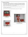
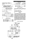
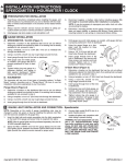
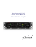
A
®
Technology
L
L-849V, STYLE A & E
LED VOLTAGE-POWERED
APPROACH LIGHTING SYSTEM
SAL-1030-V
USER’S MANUAL
STROBE APPROACH LIGHTING TECHNOLOGY
108 Fairgrounds Drive, Manlius, NY 13104
603-598-4100
V 1.1
SCOPE
This manual contains Installation, Operation, and Maintenance information for an LED-based
L-849V, Styles A & E, Unidirectional Runway Approach Lighting system manufactured by
Strobe Approach Lighting Technology (SAL Technology) for use in constant-current
powered applications. The manufacturer's designation for this equipment is SAL-1030I REIL
System.
CARTON LABELING
The SAL-1030-V REIL System consists of two Head Assemblies, two Junction Boxes, one
Master Control Unit (MCU), and three (3) frangible couplings shipped in cartons with protective
inserts.
UNPACKING
Inspect each shipping carton for external damage immediately upon receipt. There could be
damage to the contents if the carton is damaged. Promptly file a claim with the freight carrier if
you have received damaged equipment.
TOOLS RECOMMENDED
#2 Phillips screwdriver; 10-inch shank.
3/16-inch (5 mm), flat blade screwdriver; 10-inch shank.
Large (3-inch) slip-joint pliers (for pipe and lock nuts)
Wire strippers.
Wire cutters (for small gage wire).
Volt-Ohm meter
ABBREVIATIONS USED IN THIS MANUAL
MCU → Master Control Unit
J-B → Junction Box
OFH → Optical Flash Head
REIL → Runway End Identifier Lights
SLC → Series Lighting Circuit
NPT → National Pipe Tapered thread
NPS → National Pipe Straight thread (not tapered)
EMT → Electrical Metallic Tubing
DISCLAIMER
The information in this manual is believed to be accurate and up to date, however, Strobe
Approach Lighting Technology assumes no liability for damages or injuries that may result from
errors or omissions, or from the use of information presented herein. Strobe Approach Lighting
Technology reserves the right to modify this manual at its own discretion without notification to
any person or organization.
i
SAL-1030V
04 Feb. 2014
V 1.1
APPLICABLE SPECIFICATIONS
This equipment meets or exceeds the requirements in the FAA Advisory Circular, AC 150/534551B, and EB 67D.
WARRANTY
Strobe Approach Lighting Technology warrants this equipment and all of its components
when used under normal conditions. Failure of any component within from the date of shipment
will be corrected by repair or replacement, FOB Manlius, NY 13104.
USE OF GENERIC PARTS
Using parts not manufactured or supplied by Strobe Approach Technology, or unauthorized
modification of any part of this equipment, voids the warranty and could render the equipment
noncompliant with applicable FAA specifications.
IMPROPER INSTALLATION
This equipment can be damaged if the procedures and recommendations contained herein are not
observed during installation. Any damage resulting from incorrect installation will void
warranty.
CONTACT INFORMATION
Strobe Approach Lighting Technology may be contacted by the following methods:
Tele: 603-598-4100
Email: [email protected] OR [email protected]
WARNING
Do Not Depend on Interlocks For Safety
Never depend on an interlock switch alone to render the equipment safe. Always turn off and lock
out upstream power when performing maintenance on this equipment.
ii
SAL-1030V
04 Feb. 2014
V 1.1
TABLE OF CONTENTS
Page
Front Matter ---------------------------------------------------------------------------------------------------i-iv
Carton Labeling--------------------------------------------------------------------------------------i
Unpacking -------------------------------------------------------------------------------------------i
Tools Recommended------------------------------------------------------------------------------i
Abbreviations Used in This Manual --------------------------------------------------------------i
Applicable Specifications ------------------------------------------------------------------------------ i
ii
Warranty----------------------------------------------------------------------------------------------Use of Generic Parts------------------------------------------------------------------------------------- ii
Contact Information ----------------------------------------------------------------------------------- ii
Table of Contents -------------------------------------------------------------------------------------- iii
List of Figures ---------------------------------------------------------------------------------------iv
General Description ---------------------------------------------------------------------------------------- 1
Equipment Specifications ------------------------------------------------------------------------------2
Installation------------------------------------------------------------------------------------------------3 3-9
Access------------------------------------------------------------------------------------------------3
Master Control Unit--------------------------------------------------------------------------------4
Optical Heads---------------------------------------------------------------------------------------5
Zeroing and aiming---------------------------------------------------------------------------------6
Wiring------------------------------------------------------------------------------------------------7-9
Remote Control-------------------------------------------------------------------------------------8
Functional Description ------------------------------------------------------------------------------------- 10
Theory of Operation------------------------------------------------------------------------------------------ 10
Operating Instructions----------------------------------------------------------------------------------- 11-12
Troubleshooting------------------------------------------------------------------------------------------------13-14
Maintenance----------------------------------------------------------------------------------------------15
Replaceable Parts---------------------------------------------------------------------------------------16
iii
SAL-1030V
04 Feb. 2014
V 1.1
LIST OF FIGURES
PAGE
1a: Power Supply ---------------------------------------------------------------------------------------------1
1b: Flash Head ------------------------------------------------------------------------------------------------1
1c: Co-mounted Unit-------------------------------------------------------------------------------------------1
2: Master Control Unit------------------------------------------------------------------------------------ 4
3: Optical Heads------------------------------------------------------------------------------------------- 5
4: Electrical Hookup Overview-------------------------------------------------------------------------- 7
7
5: MCU Input Terminal Block--------------------------------------------------------------------------------6: Remote Control Wiring------------------------------------------------------------------------------- 8
7: Junction Box Wiring---------------------------------------------------------------------------------- 9
8: Lightning Protection---------------------------------------------------------------------------------9
9: Component Identification------------------------------------------------------------------------------- 16
iv
SAL-1030V
04 Feb. 2014
V 1.1
GENERAL DESCRIPTION
The SAL-1030-V is a voltage-powered REIL System consisting of two identical Light Units and a Master
Control Unit (MCU). Each Light Unit is made up of an Optical Head and a Junction Box. The heads and
Junction Boxes are separated for shipment and must be assembled mechanically and electrically during
installation. Each Junction Box contains a 48 Vdc power supply and provides a convenient location for
electrical connections without having to access the Optical Heads.
The MCU is in a separate enclosure that is electrically connected to the two Junction boxes by means of
power wiring and an RS-485 data bus.
The SAL-1030-V has three flash intensity modes that may be selected by remote switching.
Fig. 1a
Optical Flash Head
Fig. 1c
SAL 1030-V System
(Only one flash head shown)
Fig. 1b
Master Control Unit (MCU)
1
SAL-1030V
04 Feb. 2014
V 1.1
EQUIPMENT SPECIFICATIONS
PHYSICAL: Dimensions are in inches (mm); Weight in lbs (kg).
Master Control Unit (Figure 1a).
Dimensions ------------------------------------------------- 6.5H x 13.5W x 12D (165 x 343 x 305)
Weight: ------------------------------------------------------ 10.2 (4.6)
Optical Head (Figure 1b).
Dimensions ----------------------------------------------- 15H x 15W x 4.8D (381 x 381 x 122)
Weight: ---------------------------------------------------- 24.6(11.2)
Height is overall-See Figure 3.
Junction Box (Figure 1c).
Dimensions: --------------------------------------------- 7.9 x 9.0W x 4.5D (201 x 229 x 114)
Weight: --------------------------------------------------- 8.8 (4.0)
OPERATIONAL:
Voltage (rms) -------------------------------------------- 100 to 240 Volts, 50/60 Hz
Power: (Watts) ------------------------------------------- 50
Flashes Per Minute -------------------------------------- 120
Intensity: (Effective Candelas*, total beam spread) High: 7500 to 22500
Med: 750 to 2250
Low: 150 to 450
Beam Spread: --------------------------------------------- 30º Horizontal, 10º Vertical.
AVAILABLE OPTIONS: (Must be factory installed)
Alarm function (dry relay contacts)
Remote control by current from a Series Lighting Circuit
*Measurement method according to AC 150/5345-51B. Para. 3.4.1c.
2
SAL-1030V
04 Feb. 2014
V 1.1
INSTALLATION
In this section you will find instructions and recommendations for:
Emplacement preparations.
Installation sequence.
Accessing the various components of the system.
Mounting the Master Control Unit (MCU).
Mounting the Junction Boxes.
Mounting the Optical Heads
Zeroing the Horizontal Aiming Scale and Pointer.
Zeroing the Vertical Scale and Pointer.
Electrical connections.
EMPLACEMENT PREPARATIONS
The SAL 1030 LED REIL system requires three prepared emplacements: one for each Optical
Head, and one for the Master Control Unit (MCU). Each emplacement requires a foundation
with a 2-inch NPS or NPT female threaded receiver such as a flange bolted to a concrete pad, or
an in-ground can cover with a threaded hole. Detailed drawings for the emplacement foundations
are furnished by others.
The MCU can be installed at any convenient location and may be located several hundred feet
from the nearest Optical Head. However it may alternatively be co-located with one of the
optical heads, but separately supported.
RECOMMENDED INSTALLATION SEQUENCE (ABBREVIATED)
Install the Junction Boxes at the prescribed light positions.
Zero the Horizontal Scale at each light emplacement. The zero degree-angle is meant to
be parallel to the centerline of the runway.
Install each Optical Head onto its Junction Box with the Horizontal Pointer at the
prescribed offset angle (obtained from site drawings).
Level the Optical Head and Zero the Vertical Pointer.
Set the prescribed elevation angle at each head.
Install the Master Control Unit (may be done at any point in the sequence).
Make electrical connections.
ACCESS
• The cover to the MCU is secured by quarter-turn latches with padlock provisions on the two front
corners of the enclosure.
• Each light emplacement has an Optical Head and Junction Box.
• Junction boxes have a removeable cover secured by captive screws at each corner.
• Optical Heads do not have to be accessed for installation.
3
SAL-1030V
04 Feb. 2014
V 1.1
INSTALLATION (cont.)
THE MASTER CONTROL UNIT (See Figure 2)
Accessories needed but not shipped with the equipment due to variable site requirements.
• 2-inch NPS to EMT compression fitting (or frangible coupling).
• 2-inch EMT; length as required to set the MCU at its designated or preferred height above
local terrain.
• See "Equipment Specifications" for MCU dimensions and weight.
The Master Control Unit (MCU) is provided with a factory-installed compression fitting for 2inch EMT at the bottom surface of the enclosure. A length of 2-inch EMT and a compatible
compression fitting threaded at one end are needed, but typically provided by others unless
designated as accessory items at the time of purchase.
IMPORTANT NOTICE
When the MCU is mounted on an in-ground can, the EMT support is generally open to the can
for wire passage. The MCU is shipped with a foam plug slotted to allow wire passage. A plug is
essential to prevent free passage of air between the in-ground can and the MCU enclosure.
Failure to install this plug or to provide other means of preventing free air passage will allow
condensation to collect within the enclosure during certain atmospheric conditions and will
void the equipment warranty.
MCU
2-INCH EMT
COMPRESSION
FITTING
2 INCH EMT SECTION
(supplied by others)
2-INCH EMT COMPRESSION
FITTING WITH NPS/NPT THREADS
2-INCH NPS/NPT FLANGE
(supplied by others)
Figure 2
MCU Mounting Details
4
SAL-1030V
04 Feb. 2014
V 1.1
INSTALLATION (cont.)
The Optical Heads
Junction boxes and Optical Heads are shipped unattached
and must be joined together during installation, but the
Junction Boxes should be installed before the Optical
Heads are attached.
Parts needed for this procedure (at each emplacement):
• Optical Head
• Junction Box
• 2-inch, EMT
> Length determined by site requirements
> Not furnished with equipment
• Frangible coupling (with compression fitting)
OPTICAL HEAD
HUB
HOR AIMING
SCALE
Installation overview
The Optical Heads are mounted onto Junction Boxes and
located on each side of the runway near the runway
threshold. Location details are typically obtained from
drawings provided by others.
Each Junction Box is supported by a single 2-inchdiameter section of EMT and various couplings as shown
in Figure 3. The length of the EMT will generally be
different from site to site; therefore it is not furnished with
the equipment. The length is usually chosen to achieve a
certain overall height above grade as called out on site
drawings provided by others.
The MCU and one of the light units may be co-located at
an emplacement with two threaded receivers separated by
8 inches (203 mm) center-to-center.
Mounting and Assembly Details (Refer to Figure 3)
Use the following procedure as a guide:
• Install the frangible coupling onto the ground attachment
device (typically an in-ground can cover or a threaded floor
flange bolted to a concrete pad).
• Install the EMT and securely tighten the compression
fitting.
•
POINTER
JUNCTION
BOX
HUB
2-INCH EMT
LENGTH TO SUIT
INSTALLATION
REQUIREMENTS
(SUPPLIED BY OTHERS)
FRANGIBLE
COUPLING WITH
2-INCH
COMPRESSION
FITTING
TO THREADED GROUND ATTACHMENT
Fig 3
Typical Head Mounting Details
Set the Junction Box onto the upper end of the EMT and
lightly tighten the two hex-head bolts. Firm tightening will be done later during the aiming procedure.
Do not turn the setscrew. It has been properly set at the factory.
5
SAL-1030V
04 Feb. 2014
V 1.1
INSTALLATION (cont.)
Zeroing and Aiming Instructions
Horizontal
Optically enhanced LEDs, unlike conventional light sources, have very sharply defined beams; aiming is
therefore very critical. A horizontal scale has been provided to assist in aiming, but it must be properly
aligned with the runway in order to use it effectively. Horizontal scale alignment (zeroing) can be
performed before setting the Optical Head onto the Junction Box.
The horizontal scale is attached to the top surface of the Junction Box. The scale ranges from –15º to +15º
in increments of 1º. A pointer affixed to the Optical Head assembly indicates the aiming direction of the
head, but first, the scale must be accurately referenced to the runway. This requires orienting the Junction
Box to face exactly downrange; that is, parallel to the centerline of the runway. This can be achieved by
following the steps below:
•
•
•
•
•
Establish an aiming target such as a stake or a person placed the same offset distance from the runway
centerline as the light emplacement. The target should be at least 200 feet down range from the
emplacement.
Use an edge of the Junction Box as a sighting line and rotate the Junction Box about its supporting
pipe until the edge points directly towards the target.
Securely tighten the hex-head bolts when the Junction Box is aligned with the aiming target. The
cone-point setscrew prevents the Junction Box from turning while the bolts are being tightened. The
horizontal scale is now referenced to the runway.
Install the Optical Head onto the Junction Box by setting the head's hub over the mounting plug on
the top surface of the J-B.
Lightly tighten the hub's two hex-head bolts.
Do not turn the setscrew. It has been properly set at the factory.
•
Rotate the head until the pointer rests on the horizontal offset angle defined for this
emplacement and now firmly tighten the two hex-head bolts.
Vertical
The head is secured vertically by a zero-backlash turnbuckle. Turning the body of the turnbuckle tilts
the head. In normal operation the head will be pointing somewhat upwards; that is, above the
horizon.
You should avoid tilting the head to point below the horizon because the turnbuckle end-fittings can
become disengaged which would allow the head to swing freely on its pivots.
You will use the spirit level residing in a cavity just above the vertical pointer to zero the vertical
scale.
To zero the vertical pointer:
• Rotate the body of the turnbuckle until the level bubble lies symmetrically between the two
reference lines.
• Loosen the setscrew that holds the vertical pointer and set the pointer to 0º on the scale.
• Tighten the setscrew while the pointer rests on zero.
Use the turnbuckle to set in the vertical aiming angle prescribed for this emplacement.
THIS COMPLETES MOUNTING, ZEROING, AND AIMING
6
SAL-1030V
04 Feb. 2014
V 1.1
INSTALLATION (cont.)
Wiring
Wiring during installation consists of bringing primary
power to the Master Control Unit (MCU), and power and
communications (Comm) from the MCU to the two Junction
Boxes supporting Optical Heads. All connections are made
at terminal blocks that accept bare-wire insertions under
screw clamps. No special wire-termination tools are
required.
OPTICAL HEAD
DC POWER & COMM
Junction Boxes
J-B
Power wiring consists of three conductors. Two are required
for 120 or 240 Vac; the third is for equipment ground.
J-B
AC POWER & COMM
Comm wiring must satisfy the requirements for an EIA RS485 data bus. It must have three conductors: Two are for
balanced-line data transmission (designated as Comm A and
Comm B). The third is an isolated ground conductor. The
isolated ground is designated as CGi at the terminal blocks.
MCU
PRIMARY POWER
Figure 4
Electrical Overview
Do not connect CGi to chassis ground.
TB101
Connections in the MCU
Input Wiring
TB101 is the input terminal block for Primary Power
and Remote Control. See Figure 5.
The MCU power supply self adapts to any voltage from
100 to 260 Vac, 50 or 60 Hz.
1
2
L1
L2 O R
N E UT
3
A
4
B
10 0 T O 2 6 0 V A C
50/ 60 H z
N OT
US E D
5
C
6
D
7
24
V dc
8
LO W
9
M ED
10
H IG H
R EM OT E
C ON T R OL
Figure 5
MCU Input Terminal Block
7
SAL-1030V
04 Feb. 2014
V 1.1
INSTALLATION (cont.)
Remote Control:
Remote Control is compatible with L-854 Radio Receiver/Decoder or any switch that satisfies the function
shown in Figure 6. It consists of a four-wire circuit in which one of the conductors provides the switching
voltage (24 Vdc). The other three are activated through a switch for Low, Medium, or High intensity. For
satisfactory operation up to 1000 feet the lines from the MCU to the Remote Switch should be shielded, and
the shield should be grounded at the MCU chassis. The other end of the shield should not be grounded.
TB101
1
2
3
4
5
6
SHIELD
V+
7
DO NOT
GROUND SHIELD
AT THIS END
LOW
LOW
8
9
10
M ED
M ED
HIGH
HIGH
V+
OFF
M CU CHASSIS
GROUND
M ASTER CONTROL UNIT
Figure 6
Remote Control Wiring
REM OTE CONTROL
SWITCH.
MCU Output Wiring
TB102 is the output terminal block. It provides connections for power and communications to the Optical
Heads through the Junction Boxes. The output wiring connections are identified in Figure 6.
Separate cables are highly recommended for Power and Communications rather than using one multiconductor cable for both. Since there are two heads there would be two Power Cables and two Comm Cables
leading from the MCU to the head emplacements. Terminal Blocks are labeled for all connections at the
MCU and at each Junction Box.
Power cables would contain three conductors. Recommended colors are Black for L1, Red for L2 or Neutral,
and Green for Chassis Ground. AWG 14 would be satisfactory for a run length of 1000 feet. Power wiring
from the MCU to the Junction Boxes is identical for all voltages. There are only two power conductors and a
chassis ground conductor. One power conductor is identified as L1 at the terminal blocks. The other power
conductor is identified as "L2 or N" (Neutral).
It is not necessary to distinguish between Neutral and L2 at the MCU or the Junction Boxes.
An RS-485 compatible cable with AWG 22 (min) wire such as Belden 3106A or 3107A is recommended for
data communications. The data transmission signal is phase-sensitive; therefore a line originating as Comm
“A” at the MCU must be connected to Comm “A” at its designated Junction Box. A low capacitance, shielded
cable with two twisted pairs may be used in lieu of the Belden cable mentioned above. In this instance the two
conductors of the second twisted pair would be used as one conductor for the CGi connection.
Do not connect CGi to chassis ground.
8
SAL-1030V
04 Feb. 2014
V 1.1
INSTALLATION (cont.)
Wiring At The Junction Boxes
Optical Heads are identified as #1 and #2 at the MCU. Observe the labeling to ensure proper head address for
automatic data logging.
JUNCTION B OX FOR EITHER HEA D
1
2
3
4
5
6
7
L1
L2
CGi
A
B
GN-WH
8
9
10
TB201
THE COMM CABLE CONSISTS OF A
MINIMUM OF ONE TWISTED PAIR OF
CONDUCTORS, AN INDEPENDENT
CONDUCTOR FOR CGi (ISOLATED GND.),
AND AN OVERALL SHIELD. THE SHIELD
MUST BE TIED TO CH. GND. AT THE MCU
END ONLY.
A SECOND TWISTED PAIR JOINED AT
THE ENDS AS A SINGLE CONDUCTOR
MAY INSTEAD BE USED FOR CGi.
J-B
CHASSIS
B U-WH
B K-WH
WH
BU
5-CONDUCTOR
CABLE TO HEAD
CABLE IS PRE-ATTACHED
AT THE HEAD ASSEMBLY
THROUGH METALLIC,
WATER TIGHT FLEXIBLE
CONDUIT
LINE 1
3 CONDUCTOR POWER CABLE
FROM TB102 IN THE MCU
LINE 2 OR NEUT
CH GND
DENOTES A TWISTED PA IR
COM M -A
3 CONDUCTOR COMM CABLE
FROM TB102 IN THE MCU.
DENOTES A N OVERA LL SHIELD
COM M -B
CGi
SHIELD
SHIELD TIED AT M CU END ONLY
Figure 7
Junction Box wiring
Lightning Protection
A local ground is required at each emplacement for protection against lightning damage.
HEAD # 1
HEAD # 2
M CU
Figure 8
Lightning Protection
GROUNDING THIS EQUIPMENT TO A COUNTERPOISE COULD INCREASE THE RISK OF LIGHTNING DAMAGE
THIS COMPLETES INSTALLATION INSTRUCTIONS
9
SAL-1030V
04 Feb. 2014
V 1.1
FUNCTIONAL DESCRIPTION
The SAL 1030-V REIL is a Style A/E, current-powered system consisting of two Optical Heads and a Master
Control Unit (MCU). Each head has an associated Junction Box that contains a dc Power Supply.
The heads receive flashing and other operating commands from the MCU, and send monitored status
information in return. Selected operating parameters are shown visually on a numerical array accommodating
values up to xxxx. See Figure 10.
Operation is typically automatic, but flash intensity functions can be set in manually for checkout purposes.
The two Optical Heads flash simultaneously upon a single command from the MCU. Programming set in at
the factory controls flash rate. There are no selective programming requirements that must be set in at the
field.
The light beam is slightly greater than 10º vertically by 30º horizontally. This beam coverage is formed by the
composite effect of an array of high-performance, white LEDs.
The array is monitored in such a way that a failure of a complete row or column, or a combination that
exceeds a certain number of LEDs at random locations, will turn on an alarm signal light and cause an alarm
relay to operate. The alarm relay is for external remote distribution.
Certain Error Codes are generated as a result of monitoring. These are displayed intermittently on the foursegment numerical display.
THEORY OF OPERATION
The SAL 1030-V REIL is a micro-controller based system. Each Optical Head consists of an array of 60,
optically enhanced, high performance, LEDs arranged geometrically to form a vertical beam coverage of at
least 10º and a horizontal coverage of at least 30º.
The MCU has a single micro-controller card (LSM card) for all input and output functions. An RS-485 data
bus provides communications between the MCU and the Optical Heads. A micro-controller card in each head
communicates with the LED arrays in that head, collecting status information to send back to the LSM card.
Each head is identified by an address code for data tagging at the MCU.
A low-capacitance data transmission line, suitable for RS-485 drivers and receivers, can support satisfactory
communications at the baud rate of this system for up to 4000 feet.
While the heads communicate only with the MCU, the MCU has connections outside of the system such as
primary power, remote switching, and optionally, a remote alarm activating circuit. These external lines may
be subjected to voltage surges or other electrical disturbances. The externally connected lines are provided
with over-voltage protection within the MCU. Similar surge protection guards the RS-485 data bus to the
Optical Heads.
The MCU is powered by a 24 Vdc switchmode power supply that self adapts to an input voltage ranging from
100 to 260 volts, 50 or 60 Hz..
Each Optical Head is powered by a 48Vdc switchmode power supply located in a Junction Box (part of each
head emplacement). These power supplies also self-adapt from 100 to 260 Vac, 50 or 60 Hz.
The Head Controller cyclically scans the LED array collecting temperature, voltage, and flash information.
An alarm signal is generated if either head develops an operating condition that falls below a prescribed safe
level (EB67D). Examples are: more than 11 (<20%) failed LEDs in a single head, or an incomplete column or
row of LEDs. A fail-safe Alarm Relay (contacts close on fail) that can be used for remote alarm signaling is
also activated.
10
SAL-1030V
04 Feb. 2014
V 1.1
OPERATING INSTRUCTIONS
Controls
SW 101 is a cover-activated interlock switch that controls primary power. The plunger of SW 101 may be
pulled up to energize the MCU for service.
There are two switches in the MCU for operating control:
The MODE CONTROL rotary switch (SW 102) selects operating modes, manual or automatic (remote).
The INDEX pushbutton switch (SW 103) selects parameters for the four-digit numerical display.
The operating modes from SW 102 are:
• REM (Remote)
• Off
• MAINT (Maintenance)
• LOW
• MED (Medium)
• HIGH
Use REM to control flash intensity from CCR current level (via the Current-Sensing Module).
Use OFF to inhibit flashing while the system is energized.
Use MAINT to operate the heads in a low-level, steady (non-flashing) mode (May help to identify the
location of a non-operating LED).
Use LOW to flash the LEDs at Low intensity.
Use MED to flash the LEDs at Medium intensity.
Use HIGH to flash the LEDs at High intensity.
Depressing the INDEX switch cycles the status LEDs and the data displayed on the numerical LED array.
VOLTS: When lit the numeric array displays the average voltage across each group of 12 LEDs in both heads
combined.
TEMP: When lit the numeric array displays the average operating temperature of the LEDs in both Optical
Heads combined.
HOURS: When lit the numeric array displays the total no-fault operating hours at HIGH intensity.
To activate the system when the cover to the MCU is open and primary power is applied:
• Pull the Interlock Switch up (Service mode).
• Turn the Rotary Switch to any of the positions below:
> MAINT
> LOW
> MED
>HIGH
To activate the system for Normal Operation:
• Place the Rotary Switch in the REM position.
• Close the cover
• Apply primary power
11
SAL-1030V
04 Feb. 2014
V 1.1
STATUS MONITORING
There are two LEDs for critical status monitoring.
CAUTION: This LED lights when an abnormal, but not disabling, condition exists. It signals attention
and further investigation into the condition and its cause. Examples are:
• More than 2 LEDs have failed (composite of both heads).
• Temperature has been reported to be more than 80 ºC.
• A voltage has been reported as below 28 Vdc.
See the troubleshooting section for recommended actions if any of these conditions arise.
ALARM: This LED lights and an ALARM relay operates (de-energizes) when a disabling condition has
developed. Examples are:
• More than 12 LEDs fail to report or to flash in either head.
• One head is not reporting.
See the troubleshooting section for recommended actions if any of these conditions arise.
12
SAL-1030V
04 Feb. 2014
V 1.1
TROUBLESHOOTING
Problems addressed in this section fall into two broad categories: Those encountered upon initial
turn-on following installation, and evolving problems that occur after the system has been operating
properly for any length of time. The most common problem that will likely be encountered is failure
to flash. There are many possible causes for flash failure, especially upon initial turn-on. A flash
failure generally involves both optical heads. The reason is not that both heads are necessarily at
fault, but because the Master Controller has shut them both down due to an abnormal condition that
might affect the view presented to an approaching pilot. In fact, the system is not allowed to flash
unless both heads meet the minimum required standard of operation based on the number of nonoperating LEDs. Another problem that can cause total flash shutdown is loss of communication to
either head. Neither head is allowed to flash independently.
A. Problems occurring at installation
The most common problems occurring when a system is first turned on are failure to flash at all,
and Remote Control problems.
1. Failure to Flash.
A number of conditions could cause initial failure to flash.
• Upon applying power observe whether the numeric display and status LEDs on the
Master Control Board light up. If not, check the source of primary power, and the fuses
F1 & F2.
• Make sure the Mode Selector Switch in the MCU is set to Low, Med, or High.
• Check both Comm lines to verify that Comm-A in the MCU (TB102) goes to Comm-A
in the respective remote Junction Box (TB201), and that Comm-B similarly goes to
Comm-B.
• Observe whether the heads flash briefly (two or three flashes) directly upon applying
power. If only one head flashes briefly then quits look for a communication problem to
the other head (remember that both heads must operate in order to sustain flashing).
2. Remote Control Problem
The system fails to respond to remote control commands or responds incorrectly.
• Be sure the Mode Selector Switch is set to the REM position.
• Be sure that the Remote Circuit is wired as shown in Figure 5B.
• If the switch is set to REM and yet fails to respond correctly proceed as follows:
> At TB101 in the MCU disconnect all four Remote Control lines from the external
Remote Control Switch.
> Verify with a voltmeter that +24 Vdc is present at TB1-5.
> Temporarily connect TB101-5 and TB1-6 together and verify that the LOW mode LED
on the Master Control board lights up.
> The MED LED should light up when TB101-5 & 7 are connected.
> The HIGH LED should light up when TB101-5 & 8 are connected.
If these conditions occur as described the problem must be in the external Remote
Control circuit. See "Troubleshooting the external Remote Control circuit".
If these conditions fail as described the Master Control board is faulty. Replace the circuit
board.
13
SAL-1030V
04 Feb. 2014
V 1.1
TROUBLESHOOTING (cont)
•
•
•
Reconnect the external V+ wire to TB101-5 and again measure the voltage at that
terminal. If it measures +24 Vdc, the external V+ line is OK. If it measures zero the line
must be shorted.
If TB101-5 checks out OK, proceed to re-connect LOW, MED, & HIGH while checking
the voltage at TB101-5 after each one is connected. Any connection that affects the
24Vdc level must be investigated and corrected.
If a Remote Control problem persists after all of the external circuit wires are connected
and verified the problem is likely due to interference on the wires between the MCU and
the remote switch. These wires should be shielded and the shield tied to the MCU
chassis. The shield should NOT be tied at the remote switch end.
B. Evolving Problems
The manifestation of an evolving problem is nearly always a failure of both heads to flash. That
is because the software instructions are that unsatisfactory operation within either head shall
disable flashing of both heads to prevent a confusing presentation to a pilot. Therefore steps must
be taken to identify the source of the problem, which most likely will be confined to only one
head.
When flashing has been shut down due to a serious malfunction the system will override the
shutdown briefly upon cycling primary power. This enables one to evaluate the cause by directly
viewing each of the heads, as power is re-applied.
• Choose the MAINT MODE position on the Mode Selector Switch. In this mode the heads are
operated in a steady, low level of illumination suitable for direct viewing. One can quickly
ascertain which head is creating the malfunction by not responding at all, or exhibiting a
malfunctioning sector.
• If none of the LEDs in one of the heads are operating check the power supply in that head's
Junction Box. Look for 48 Vdc between the Blue and White wires (plus & minus 48 Volts) at
TB201. If there is no dc voltage at those terminals verify that primary power is present at
terminals L1 & L2. With primary power present but no dc voltage the power supply is
defective and must be replaced.
• If the dc voltage checks OK then the problem could be in the Comm cable or connections.
• If dc voltage is present and the LEDs are on (steady mode), but a portion of the array is unlit
the problem resides within the head. Contact Customer Service at SAL Technology if this
condition has been ascertained.
14
SAL-1030V
04 Feb. 2014
V 1.1
MAINTENANCE
The following tips will help assure long, reliable operation.
•
•
•
•
•
•
•
•
Keep door and cover seals in good condition. Repair or replace any that are damaged.
Inspect and maintain grounding at each emplacement.
Keep earth grounds separate from any counterpoise conductor.
Be sure there is no free air exchange between an in-ground chamber and the MCU.
Be sure there is no free air exchange between an in-ground chamber and a Junction Box.
Periodically check the tightness of terminal block clamping screws.
Inspect the flexible conduit between the Optical Heads and associated Junction Boxes
Repair or replace any damaged conduit or fitting.
15
SAL-1030V
04 Feb. 2014
V 1.1
REPLACEABLE PARTS
PCB 101
ALARM
CONTROL MODULE
M AINT LOW
M ED
ASS'Y
OFF
HIGH
REM
344-50515
PS101
SW103
MAINT
LOW
MED
HIGH
NORM
CAUTION
VOLTS
TEMP
HOURS
8 8 8 8
F103
SW102
CABLE ACCESS
TB101
F1014
5
6
F1027
8
9
GS101
GS102
NC C NO
ALARM
10
1
2
3
OUTPUT TERMINAL BLOCK
3
TB103
2
SW101
1
1
INPUT TERMINAL BLOCK
MOV101
TB102
2
3
4
5
6
7
8
9
10
4
Figure 9
Component Identification
Table 4, Replaceable Parts
REF
F 101, F102, 103
MOV101
PS 101
PS 201
MOV-101, 102
PCB-101
SW101, 102
FH 1030
DESCRIPTION
Fuse, 1.5 A
250 Vac Varistor
24 Vdc Power supply
48 Vdc Power Supply (Junction Box location)
Surge Suppressor, 130 Vac
Printed Circuit Board, Master Control
Interlock Switch
Flash Head Assembly
PN
55-00267
55-00302
44-00104
44-00146
55-00202
344-30105
44-00107
344-30520
16
SAL-1030V
04 Feb. 2014