1
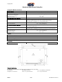
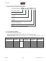
Copyright IDS
Installation and User Manual
PV Smart String Box active (with contactors)
SSB-A-14-140, SSB-A-25-250
Version 2.02
Copyright IDS
Datasheet SOLO Smart String Box
Type
SSB-A-14-140
SSB-A-25-250
Electrical Data
Maximum operating voltage
Maximum output current DC
Maximum number PV entrances (strings)
UDC
IDCmax
1000 VDC
Maximal input current DC per string
String current measurement range
ISTRmax
ISTR
10 A
0.5 – 15 A
Reverse string current measuring
Surge arrester
State indication lamp on the door
ISTR rev
Yes
Type II
Yes
140 A
14
Test voltage
Surge arrester fault indication
250 A
25
2.5 kV, 50 Hz, 1 min
Yes (auxiliary dry contacts)
Mechanical Data
Dimensions in mm
Weight
WxDxH
m
700 x 270 x 500
26 kg
29 kg
Colour
Enclosure material
Protection class according to EN 60529
RAL 7035 (light grey)
Glass-fibre-reinforced and halogenfree polyester
IP55 (outdoor)
Impact strength according to EN 50102
Max air humidity
IK10
95 %
Ambient temperature range
UV proof
PV(+) Connections outer diameter
Fastening torque nominal / maximal
Strand wire cross-section
Tamb
-20 °C ... +60 °C
Yes
4.5 - 10 mm (cable gland)
1.5 Nm / 1.8 Nm
0.5 - 10 mm2
PV(-) Connections outer diameter
Spring terminals through type
(strand wire cross-section)
4.5 - 10 mm (cable gland)
Inverter connections outer diameter
Fastening torque nominal / maximal
Cable lug size
Grounding connection outer diameter
Fastening torque nominal / maximal
Cable lug size
22 - 32 mm (cable gland)
25 Nm
M12
7 - 13 mm (cable gland)
25 Nm
M12
0.5 - 10 mm2
String Box Interface
DC contactor control input
Cable outer diameter
Spring terminals through type
(strand wire cross-section)
Signal cable
IDS/kc
230 VAC +10%/-15%, 50 Hz ± 10 %, Pmax = 30W
4.5mm – 10mm (cable gland)
0.25 – 4 mm2
3 x 1.5 mm2 LNPE
3/24
IUM SSB en V2.02 0311
Copyright IDS
Datasheet SOLO Smart String Box
String Box Monitor Interface
Ready feedback
Ready feedback output
Separate feedback for each Smart String Box; Closed dry contact when ready
24 VAC/DC (18 – 36 V), 2 A at 30 VDC
4.5 – 10 mm (cable gland)
Cable outer diameter
Spring terminals through type
(strand wire cross-section)
Cable cross section
0.25 – 4 mm2
2 x 1 mm2
Fibre optical interface (standard)
Cable type for optical interface
Ring type serial interface connection
Outdoor, UV light resistant, armoured
Fibre type: Multimode 62,5/125 or 50/125; Cable end port ST type
Recommended: A-VQ(BN)H 1x4, Corning Cable Systems
ST port transmitter and receiver
4.5 – 10 mm (cable gland)
Terminals for glass fibre
Cable outer diameter
RS 485 serial interface (optional)
Separable screw terminal with. 6 pins for easy bus wiring. Galvanically isolated
from monitoring electronic.
Outdoor, UV light resistant
Recommended: UNITRONIC® Li2YCYv(TP) 2x2x0,5 or 3x2x0,5, Lapp Kabel
Cable type for RS485 interface
Screw type separable terminals:
Cable outer diameter
Cable cross section
4.5 – 10 mm (cable gland)
0.5 – 1 mm2
Options
Stainless steel enclosure
Fuses with visual indication when tripped
PV(–) disconnect type terminals
Maximum operating voltage 1200 VDC
Standards
CE conformity / EMC
Yes / EN 61000-6-2, EN 61000-6-4 / EN 50178
Subject to change, March 2011
Ordering Information
For technical or commercial information please contact the IDS sales office
IDS Trade AG
[email protected] • www.ids.ch
IDS/kc
Samstagernstrasse 55
Phone +41 (0)44 562 06 00
4/24
CH – 8832 Wollerau / Switzerland
Fax +41 (0)44 562 06 06
IUM SSB en V2.02 0311
Copyright IDS
Contents
1
2
3
4
5
6
7
8
Type Code for PV Smart String Box ................................................................................................6
Fuse Selection Guide ......................................................................................................................6
Introduction ......................................................................................................................................7
Disclaimer................................................................................................................................8
3.1
General Safety Instructions .....................................................................................................8
3.2
Description of the Symbols and Warning Signs Used ............................................................8
3.3
Scope of Delivery ....................................................................................................................8
3.4
Type Label...............................................................................................................................9
3.5
Warnings ..........................................................................................................................................9
Installation of the SOLO String Box ...............................................................................................10
Opening the SOLO String Box Housing Door .......................................................................10
5.1
Opening the SOLO String Box Protective Cover ..................................................................11
5.2
SOLO String Box Design ......................................................................................................12
5.3
Location Selection .................................................................................................................13
5.4
Mechanical Installation ..........................................................................................................13
5.5
Electrical Installation .............................................................................................................14
5.6
5.6.1 Electrical Connections of the PV Strings ..........................................................................14
5.6.2 Overview of the electrical connections .............................................................................16
5.6.3 Fuse Selection ..................................................................................................................16
5.6.4 Power Cable Connections from Inverter to SOLO String Box ..........................................16
5.6.5 Connection of String Box Control Line and Feedback to the Inverter ..............................17
5.6.6 Connection of the Serial Interface for the String Box Monitoring .....................................17
SOLO String Box Commissioning..................................................................................................18
String Box Address Selection ...............................................................................................18
6.1
Turning the SOLO String Box On .........................................................................................18
6.2
Turning the SOLO String Box Off .........................................................................................19
6.3
Replacing defective Fuse Links and Surge Arresters ...........................................................20
6.4
6.4.1 Replacing a Fuse ..............................................................................................................20
6.4.2 Changing a Surge Arrester ...............................................................................................21
Declaration of Conformity ..............................................................................................................22
Contacts .........................................................................................................................................24
IDS/kc
5/24
IUM SSB en V2.02 0311
Copyright IDS
ype code o SO O S a t St
1 Type Code for PV Smart String Box
Typical Part Number
g o
SSB-A-25-250-1-0
SMART STRING BOX
A-SOLO String Box with DC Contactors.
Number of Inputs:
14 - Inputs
25 - Inputs
Nominal Current:
140 Amps
250 Amps
Version:
1-Max PV string voltage: 1000Vdc
2-Max PV string voltage: 1200Vdc
Revision:
Figure 1.1 Type code for PV Smart String Box
2 Fuse Selection Guide
The fuse selection must follow the rules below:
-
Maximum DC operating voltage of the fuse must be: 1.2 x nominal voltage of string
Rated current of the fuse must be higher or equal than: 1.6 x ISC at standard conditions (STC) (ISC – short
circuit current of panel)
Figure 2.1 Fuse selection
ISC: short circuit curRated current
rent of panel at STC
of the fuse
[A]
[A]
≤2A
4A
≤3A
6A
≤5A
8A
≤6A
10 A
≤8A
12 A
≤ 10 A
16 A
IDS/kc
Size
[mm]
10x38
Pre-arching
Joule integral
2
[A s] L/R=2ms
3.3
5.5
8
11
23
35
6/24
Operating Joule
2
integral [A s]
L/R=2 ms
28
45
62
88
180
270
IDS
article number
ART-07020
ART-07021
ART-07022
ART-07807
ART-07764
ART-07023
IUM SSB en V2.02 0311
Copyright IDS
3 Introduction
The SOLO String Box is used to merge the electrical energy of the single PV module strings. Preferably the
string box should be placed close to the PV fields. The box is also used to disconnect the DC lines from the
inverter. Several SOLO String Boxes can be connected in parallel to feed one tracker input of SOLO inverter.
PV Feld 1
PV Inverter
Smart String Box
PV1+
PV1PV2+
PV2-
DC+
DC-
+
PE
Contactor
control
PE
Contactor control 1
PVn+
PVn- Feedback
Feedback 1
Serial interface
Serial interface
PV Feld 2
Tracker1
-
Smart String Box
PV1+
PV1PV2+
PV2PVn+
PVn-
DC+
DCPE
Contactor
control
Feedback
L1
L2
L3
PE
PE
Contactor control 2
Feedback 2
Serial interface
PV Feld 6
Smart String Box
PV1+
PV1PV2+
PV2-
DC+
DC-
+
-
Tracker3
PE
Contactor control 5
PE
Contactor
control
PVn+
PVn- Feedback
Feedback 5
PE
Contactor control 6
Serial interface
Feedback 6
Figure 3.1 Exemplary overall scheme of a PV installation with Smart String Boxes
A different number of PV strings can be connected depending on the string box type. The positive poles of the
separate power feeds are protected individually, whereas the type of the fuses must correspond to the
maximum PV module string current.
The separate string currents are brought together through coupling joints and contactors toward the two DC
output terminals. The currents are monitored and via serial interface (fibre optical or optional RS 485) sent to
the data collector, which can be a part of the inverter or a separate module.
If an overvoltage occurs the accruing energy is discharged thorough a surge arrester.
Figure 3.2 Scheme of the SOLO Smart String Box with inputs for 25 PV strings
IDS/kc
7/24
IUM SSB en V2.02 0311
Copyright IDS
3.1
Disclaimer
IDS delivers optimized and tested equipment like Inverters and string boxes for Solar Power Plants.
The correct integration and interconnection of the equipment according to the manuals and
datasheets from IDS is the responsibility of the System Integrator. IDS does not assume any liability
for system design, dimensioning, build-up and the performance of the system. Claims because of
downtime are excluded.
The contents of the written text are reviewed for compliance with the hardware and software described below.
However, inaccuracies cannot be excluded, thus preventing us from supplying a full warranty for full compliance. The data supplied in the current manual is reviewed regularly. Corrections are included in subsequent
editions.
In case of violation of the installation instructions warranty claims will not be accepted.
We discard any liability in cases of accidents and material damage, caused by inappropriate handling,
undertaking of works by unauthorized personnel and the resulting damages on persons and device, as well as
for any resulting subsequent damages.
3.2
General Safety Instructions
Photovoltaic installations operate with lethal voltages. The works described here should be performed only by
authorized specialized personnel that are familiar with the installation, mounting, commissioning and operation
of PV installation. This manual must be read and understood before the installation or the commissioning
takes place.
Unauthorized personnel are not allowed to open the SOLO String Box.
The SOLO String Box may only be used for the envisaged purposes. The faultless and safe operation of the
product assumes appropriate transport, specialized storage, installation and mounting as well as careful
manipulation and maintenance.
The relevant regional and country-specific regulations and instructions must be obeyed. The requirements
described, e.g. the placement location or the installation instructions (e.g. connection profiles, torques, etc.)
must be taken under consideration at all costs.
3.3
Description of the Symbols and Warning Signs Used
!
WARNING!
The disobedience of this warning sign may lead to death or serious body injuries to persons.
!
CAUTION!
The disobedience of this warning sign could lead to property damage.
3.4
Scope of Delivery
Quantity
1 pcs.
2 pcs.
4 pcs.
2 pcs.
2 pcs.
1 pcs.
1 pcs.
IDS/kc
Article
Smart String Box
Plastic keys (one normal and one for the transport)
Wall mounting kit
Fuses for the strings
Fuses for the Power Supply Box (PSB)
Fuse for the String Box Monitor (SBM)
Plug for connection of the glass fibre interface (bypass the SBM’s)
8/24
IUM SSB en V2.02 0311
Copyright IDS
3.5
Type Label
The type label with the product identification is
located in the string box on the right side under the
protective cover as shown in Figure 5.4. The label is
shown in Figure 3.3
Product
identification
Serial number
Figure 3.3 Example of a type label
4 Warnings
!
!
!
!
IDS/kc
WARNING!
The installation instruction must be obeyed, in particular the provisions for the installation of
power current devices, for the electrical equipment of processing and manipulation machines, for
the equipment of power current devices with electronic operation tools, as well as the regulations
for the professional use of tools and personal protective equipment.
WARNING!
The device must be installed, commissioned and maintained only by qualified personnel.
WARNING!
The installation operates under life-threatening voltages. The PV module strings can be under
voltage even when the SOLO String Box switch is turned off and the string protections are
detached. The DC line toward the inverter can be under voltage even when the SOLO String Box
switch is turned off. In addition, consider the discharge time of the inverter capacitors which is
approximately 10 minutes!
WARNING!
The SOLO String Box is a part of an entire PV installation. Therefore, please consider all warnings
on the SOLO String Box and on the inverter! An automatic restart can take place after a network or
photovoltaic voltage interruption.
9/24
IUM SSB en V2.02 0311
Copyright IDS
5 Installation of the SOLO String Box
5.1
Opening the SOLO String Box Housing Door
The SOLO String Box door is closed with the use of the supplied key.
Unlocking the cap
by plastic key
String box state Indication lamp
Figure 5.1 SOLO Smart String Box housing door
IDS/kc
10/24
IUM SSB en V2.02 0311
Copyright IDS
5.2
Opening the SOLO String Box Protective Cover
!
WARNING!
Even if main switch is turned off the PV side and the DC output side might be under lethal DC
voltage!
Removing of this protective cover shall be done by authorized and qualified personnel only!
Any liability is excluded in case this rule is not respected!
The protective cover of the SOLO String Box cannot be dismounted when the main switch is “on”. In order to
remove the protective cover please put the main switch in “off” position as shown on the Figure 5.2. Then
unlock the screws by slotted screw driver (1/4 revolution) as shown on the same picture.
Screw
DC-Switch
ON/OFF
String box
address
Figure 5.2 SOLO Smart String Box protective cover
PV+ In
PVPV- In
PV+
230VAC
power supply
DC- Out
DC+ Out
230VAC contactor control
Figure 5.3 Interior view – Potentially lethal voltages location when the main switch is off
IDS/kc
11/24
IUM SSB en V2.02 0311
Copyright IDS
5.3
SOLO String Box Design
String current measurement electronic
Surge arrester
PV- Contactor
Fuse holders
PV+ Contactor
PV+ string terminals
Type label
PV- string terminals
String box monitor
electronic
DCGlass fibre optic
interface
DC+
PE
RS485 interface
Power supply 230VAC
Contactor control, 230VAC
Figure 5.4 SOLO String Box (interior view)
Climate valve
Serial interface cables
PV String inputs
Cables power supply for monitor electronic
Cables contactors switch on
Climate valve
DC output
PE input
DC output
Figure 5.5 Cable glands on SOLO Smart String Box (exterior view)
IDS/kc
12/24
IUM SSB en V2.02 0311
Copyright IDS
Figure 5.6 Cable glands in the SOLO Smart String Box (interior view)
5.4
-
5.5
-
Location Selection
The SOLO String Box is suitable for outdoor installation and should be placed as close as possible to the
PV modules in order to minimize cable length.
The String Box should be freely accessible for maintenance work.
A location without direct sunlight should be chosen.
The SOLO String Box should be mounted in a way, minimizing or preventing the collection of water, dirt
and moss development.
Mechanical Installation
The supplied fitting materials should be used where possible.
The SOLO String Box must be mounted vertically, with the cable holdings on the bottom side.
Water must never reach the inside of the box!
The SOLO String Box should be mounted on a wall with the help of the supplied mounting clips.
Figure 5.7 Dimension drawing SSB-A-14, SSB-A-25
IDS/kc
13/24
IUM SSB en V2.02 0311
Copyright IDS
The two climate valves, (see front view and rear view) must not be covered. They ensure the air circulation
inside the SOLO Smart String Box.
Figure 5.8 Climate valve interior view
5.6
Figure 5.9 Climate valve exterior view
Electrical Installation
!
!
CAUTION!
The works described may be executed only by electricians trained for PV installation.
WARNING!
The PV module strings can be under voltage even when the SOLO String Box switch is turned off
and the string protections are detached. The DC line toward the inverter can be under voltage even
when the SOLO String Box switch is turned off. In addition, consider the discharge times of the
inverter capacitors which is approximately 10 minutes!
!
CAUTION!
The power supply lines must be mounted in a way that won’t allow them to be damaged by rodents.
!
CAUTION!
The electrical lines must not come in contact with flammable materials.
5.6.1 Electrical Connections of the PV Strings
!
1.
2.
3.
4.
CAUTION!
Never feed a DC inlet with voltages higher than 1000V. Higher voltages lead to Box damages. In
case of breach of this rule all warranties will expire and no liability for consequential damages will
be undertaken.
Removing the fuses out of the fuse holders
Connect the PV string cables in the designated terminals
Measure the string voltage and check the polarity
Insert the fuses again
The correct polarity must be observed during this procedure. In case of incorrect polarity the SOLO String Box
and the PV modules might be damaged! The connecting points are visible in the following pictures:
Figure 5.10 PV minus string terminals
IDS/kc
14/24
Figure 5.11 PV minus string disconnect terminals
IUM SSB en V2.02 0311
Copyright IDS
!
WARNING!
Never break the current flow according to based on wrong poled strings by removing the fuses
from the fuse holders.
The String Box Monitor inside the Smart String Box with 25 inputs (SSB-A-25) is mounted on a swivelling
plate, which can be opened to install the PV+ strings cables. For this, the two plastic screws on the right side
of the plate (Figure 5.12) have to be loosened completely. The plate with the monitoring can be swivelled to
the left until it is kept magnetically (Figure 5.13).The PV+ terminals are now accessible.
!
WARNING!
It is not allowed to open the fuse holder while current flows.
Positive poles
of the PV
strings
Slotted cylinder-head screw
Figure 5.12 Preparation for the connection of the PV+ terminals
in the SSB-A-25
Figure 5.13 PV+ string terminals
IDS/kc
15/24
IUM SSB en V2.02 0311
Copyright IDS
5.6.2 Overview of the electrical connections
The following table gives a brief overview of the electrical connections and its terminal numbers. Please infer
detailed information from the following sub-chapters or from the datasheet.
Table 5.1 Overview of the electrical connections
Terminal
DC +
DC PE
PV1 +…
PV25 +
10X1 PV1 10X1 PV25 10X2/1
10X2/2
10X2/3
10X2/4
Rx, Tx
B, A, GND
Function
Supply cable to inverter
Supply cable to inverter
Grounding connection Smart String
Box
Connections string wires
Specification
Positive pole
Negative pole
Connections string wires
Negative poles
Ready feedback
24 VDC
DC contactor control
Supply String Box Monitor
Connection of the fibre glass
Connection serial interface RS485
230 VAC
Positive poles
Correspondent to the datasheet
Correspondent to the datasheet
5.6.3 Fuse Selection
The fuses are pre-installed at factory according to the SOLO String Box type. The fuses have to be selected
according to Chapter 2 (Fuse Type Selection).
5.6.4 Power Cable Connections from Inverter to SOLO String Box
1.
2.
3.
4.
For installation, the protective transparent plate must be unscrewed and detached from the box.
First, the grounding cable must be connected with a cable lug to the foreseen screw joint.
The supply cables to the inverter (Figure 5.14) are connected with cable lugs to the foreseen screw joints.
The correct polarity must be observed!
The protective transparent plate must be mounted back and screwed!
DCDC+
PE
Figure 5.14 Connection of PE, DC+ and DC- output to the inverter
IDS/kc
16/24
IUM SSB en V2.02 0311
Copyright IDS
5.6.5 Connection of String Box Control Line and Feedback to the Inverter
The connection of DC+ and DC- terminals to PV+ and PV- string joints is done by two contactors 10K1 and
10K2 respectively. They are switched on by 230VAC control line from inverter connected to control terminals
10X2/3 and 10X2/4 as shown in Figure 5.15.
The String Box ready feedback signal is connected to the terminals 10X2/1 and 10X2/2. The signal has to be
run to the SOLO inverter. Is the String Box not ready, despite the actuation of the contactors, the SOLO
inverter will report a warning. In case of a warning, the modules of the surge arresters have to be checked
(green/red indicator), and if needed exchanged. If still a warning occurs, despite of intact surge arrester
modules, the DC contactors have to be checked and maybe exchanged.
Ready feedback
Contactor control, 230VAC
Figure 5.15 Connection terminals to signal cables
5.6.6 Connection of the Serial Interface for the String Box Monitoring
The communication for the String Box Monitoring can by realized by using the glass fibre interface (standard),
or the RS485 interface (optional). The glass fibre interface requires a ring topology between the data logger in
the inverter and the string boxes. Starting from the inverter the ring topology has to be connected from string
box to string box with increasing address numbering.
Whereas the RS485 has to be realized as a bus and terminated in the last String Box with the termination
resistance (shift the white switches to ON).
RS485 terminals
Glass fibre transmitter and receiver
Figure 5.16 Signal cable wiring – String Box
Ready connection to the inverter
IDS/kc
Shift to ON for activation the termination
resistance
Figure 5.17 Signal cable wiring – String Box
Monitor electronic power supply
17/24
IUM SSB en V2.02 0311
Copyright IDS
6 SOLO String Box Commissioning
6.1
String Box Address Selection
All String Boxes connected to a common serial interface should have unique addresses. With the two installed
address selection keys it is possible to address up to 100 string boxes in one bus. The selected address
number is indicated by the help also of LED seven segment indicators, Figure 6.1. The two empty rectangulars
on left side (label in Figure 6.1) are to write in with permanent marker the selected address during
commisioning.
Write with a permanent
marker the selected
address
Seven segment indication of the selected
address
Keys for address
selection by the help of
screw driver
Figure 6.1 Setting the address of the String Box Monitor unit
6.2
Turning the SOLO String Box On
Make sure that the PV strings, DC+, DC-, signal and PE cables are installed correctly in the SOLO String Box.
Check if the fuse links sizes are rated for the correct current. The fuse rating must comply with the rules
defined in Chapter 2 - Fuse selection guide.
!
!
IDS/kc
WARNING!
A wrong size of the fuse link can lead to damages both to the SOLO String Box and the PV strings.
WARNING!
Danger of an electric shock
Mount the plastic protective cover for protection against direct contact before proceeding with the
commissioning.
18/24
IUM SSB en V2.02 0311
Copyright IDS
The protective cover of the SOLO String Box can be dismounted or mounted only when the main switch is
turned off (Figure 6.2).
Screw
Selected
address
indicator
DC-Switch
ON/OFF
Figure 6.2 Protective cover
The screws of the SOLO String Box protective cover can be locked with the use of a slotted screwdriver, with
a quarter of a revolution clockwise.
When the PV modules in the PV installation are connected properly, the SOLO String Box is ready for
operation. For the commissioning of the SOLO String Box, please observe also the instructions described in
the user manual of the photovoltaic inverter.
To connect the PV modules to the photovoltaic inverter, turn the main switch to “ON” position.
Close and lock the SOLO String Box door. The indication lamp on the door should glow with red light. If the
lamp is blinking this is an indication for a surge arrester or contactors or monitor electronic fault.
!
CAUTION!
The door must be closed properly in order to prevent penetration of dust and humidity.
!
CAUTION!
Contaminations on the rubber seal must be avoided at any cost. Damaged rubber seals must be
replaced immediately.
6.3
Turning the SOLO String Box Off
In order to separate the PV modules from a photovoltaic inverter, turn the main switch in the “Off” position.
!
IDS/kc
CAUTION!
Please observe the instructions supplied in the user manual of your photovoltaic inverter.
19/24
IUM SSB en V2.02 0311
Copyright IDS
6.4
Replacing defective Fuse Links and Surge Arresters
!
CAUTION!
The works described below may be executed only by electricians trained for PV installation.
!
CAUTION!
Use only original fuses. In case of use of products manufactured and offered by third parties the
protection of the installation will no longer be secured.
!
WARNING!
The PV module strings can be under voltage even when the SOLO String Box switch is turned off.
The DC line toward the inverter can be under voltage even when the SOLO String Box switch is
turned off. In addition, consider the discharge times of the inverter capacitors which is
approximately 10 minutes!
6.4.1 Replacing a Fuse
!
1.
2.
3.
4.
5.
6.
7.
8.
9.
CAUTION!
Please observe the instructions supplied in the user manual of your photovoltaic inverter.
Check through the data logger interface which string is not producing current. This can be an indication of
a damaged fuse.
Open the string box door.
Turn the main switch to “Off”.
Replace the fuse link by pulling out the string fuse insert.
Replace the fuse link with the correct rated current complying with the rules defined in Chapter 2 - Fuse
selection guide.
Close the string fuse insert.
Put the protective cover.
Turn the main switch on. The string is operational again.
Close and lock the string box door.
Figure 6.3 Open fuse link
!
IDS/kc
WARNING!
A wrong size of the fuse link can lead to damages both to the SOLO String Box and the PV strings.
20/24
IUM SSB en V2.02 0311
Copyright IDS
6.4.2 Changing a Surge Arrester
The green indicator of the surge arrester will change its colour to red when it tripped.
Figure 6.4 Surge arrester
The surge arrester is monitored by auxiliary potential free contacts.
!
1.
2.
3.
Open the SOLO String Box door.
Turn the main switch off.
Unscrew and dismantle the protective cover of the SOLO String Box
!
-
CAUTION!
The works described below must be executed only by electricians trained for PV installation.
WARNING!
The PV module strings can be under voltage even when the SOLO String Box switch is turned off.
The DC line toward the inverter can be under voltage even when the SOLO String Box switch is
turned off. In addition, consider the discharge times of the inverter capacitors which is
approximately 10 minutes!
Remove the defective surge arrester(s) through pulling it out of the fuse holder and place a new one.
Figure 6.5 Removing of a damaged surge
arrester
1.
2.
3.
Put the protective cover.
Turn the main switch on.
Close and lock the string box door.
IDS/kc
21/24
IUM SSB en V2.02 0311
Copyright IDS
7 Declaration of Conformity
IDS/kc
22/24
IUM SSB en V2.02 0311
Copyright IDS
Notes
…………………………………………………………………………………………..
…………………………………………………………………………………………..
…………………………………………………………………………………………..
…………………………………………………………………………………………..
…………………………………………………………………………………………..
…………………………………………………………………………………………..
…………………………………………………………………………………………..
…………………………………………………………………………………………..
…………………………………………………………………………………………..
…………………………………………………………………………………………..
…………………………………………………………………………………………..
…………………………………………………………………………………………..
…………………………………………………………………………………………..
…………………………………………………………………………………………..
…………………………………………………………………………………………..
…………………………………………………………………………………………..
…………………………………………………………………………………………..
…………………………………………………………………………………………..
…………………………………………………………………………………………..
…………………………………………………………………………………………..
…………………………………………………………………………………………..
…………………………………………………………………………………………..
…………………………………………………………………………………………..
…………………………………………………………………………………………..
…………………………………………………………………………………………..
…………………………………………………………………………………………..
…………………………………………………………………………………………..
…………………………………………………………………………………………..
…………………………………………………………………………………………..
…………………………………………………………………………………………..
IDS/kc
23/24
IUM SSB en V2.02 0311
Copyright IDS
8 Contacts
Sales
IDS Trade AG
Samstagernstrasse 55
CH-8832 Wollerau
Switzerland
Tel.:
Fax:
E-Mail:
Internet:
+41 43 888 9315
+41 43 888 9316
[email protected]
www.ids.ch
Service
Integral Drive Systems AG
Technoparkstrasse 1
CH-8005 Zürich
Switzerland
Tel.:
Fax:
E-Mail:
Internet:
+41 44 562 0690
+41 44 562 0606
[email protected]
www.ids.ch
IDS/kc
24/24
IUM SSB en V2.02 0311