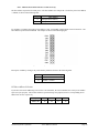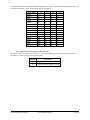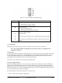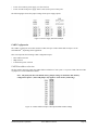
1
Janus-MM User Manual
Dual CAN ports, carrier for wireless and GPS modules
User Manual v1.06
© Copyright 2008
Diamond Systems Corporation
1255 Terra Bella Ave.
Mountain View, CA 94043
Tel (650) 810-2500
Fax (650) 810-2525
www.diamondsystems.com
Table of Contents
INTRODUCTION....................................................................................................................... 5
DESCRIPTION AND FEATURES............................................................................................ 5
FUNCTIONAL OVERVIEW................................................................................................... 5
BOARD DESCRIPTION...................................................................................................... 7
CONNECTOR SUMMARY.................................................................................................... 8
JUMPER SUMMARY......................................................................................................... 8
CONNECTORS........................................................................................................................ 9
PC/104 ISA BUS........................................................................................................ 9
CAN PORTS.......................................................................................................... 10
CAN PORT A........................................................................................................ 10
CAN PORT B........................................................................................................ 10
OPTIONAL CAN PORT A.......................................................................................... 11
OPTIONAL CAN PORT B.......................................................................................... 11
EXTERNAL MODEM ACCESS PORT................................................................................... 11
GPS INTERFACE......................................................................................................... 13
GPS BACKUP POWER AND PPS SIGNAL CONNECTOR.................................................... 13
GPS RECEIVER CONNECTOR..................................................................................... 13
SOCKETMODEMTM CONNECTORS................................................................................... 14
J20/J21 CONNECTOR PIN LAYOUT............................................................................. 14
J22 CONNECTOR PIN LAYOUT................................................................................... 16
J23 CONNECTOR PIN LAYOUT................................................................................... 16
BOARD CONFIGURATION........................................................................................................ 17
CAN CONFIGURATION.................................................................................................. 17
CAN BASE ADDRESS SELECTION............................................................................... 17
MEMORY BASE ADDRESS SELECTION........................................................................... 18
I/O BASE ADDRESS SELECTION.................................................................................. 20
CAN IRQ SELECTION............................................................................................. 22
CAN TERMINATION, SLEW RATE AND POWER SUPPLY SELECTION..................................... 22
UART CONFIGURATION................................................................................................ 60
UART BASE ADDRESS SELECTION............................................................................... 60
UART IRQ SELECTION........................................................................................... 61
UART FUNCTION AND POWER SELECTION.................................................................... 62
GPS CONFIGURATION - POWER SELECTION...................................................................... 64
MODULE INSTALLATION......................................................................................................... 65
MULTITECH SOCKETMODEM INSTALLATION......................................................................... 65
TRIMBLE LASSEN GPS MODULE INSTALLATION................................................................... 67
PC/104 EXTENDER INSTALLATION INSTRUCTIONS................................................................ 71
SPECIFICATIONS................................................................................................................... 72
CAN CIRCUIT............................................................................................................ 72
Diamond Systems Corporation
Janus-MM User Manual
Page 2
WIRELESS MODULES.................................................................................................... 72
GPS MODULES.......................................................................................................... 72
GENERAL................................................................................................................... 72
ADDITIONAL INFORMATION...................................................................................................... 73
TECHNICAL SUPPORT............................................................................................................ 74
APPENDIX A....................................................................................................................... 75
APPENDIX B....................................................................................................................... 77
Figures
Figure 1: Janus-MM Block Diagram............................................................................................... 6
Figure 2: Janus-MM Board Layout..................................................................................................7
Figure 3: J1 and J2 Connectors........................................................................................................9
Figure 4: J7 Connector...................................................................................................................10
Figure 5: J8 Connector...................................................................................................................10
Figure 6: J14 Connector.................................................................................................................11
Figure 7: J15 Connector.................................................................................................................11
Figure 8: J13 Connector.................................................................................................................12
Figure 9: J12 Connector.................................................................................................................13
Figure 10: SmartModem Connector Signals..................................................................................14
Figure 11: J4 Base Address Jumper with Option Default CAN Settings...................................... 17
Figure 12: Memory Base Address Selection Example.................................................................. 20
Figure 13: J5 Jumper with Default Settings...................................................................................22
Figure 14: J10 and J11 Jumpers with Default Settings..................................................................23
Figure 15: Power Supply Selection Example................................................................................ 60
Figure 16: J4 Base Address Jumper with Option Default UART Settings....................................60
Figure 17: J6 Jumper with Default Settings...................................................................................61
Figure 18: Shared IRQ Selection................................................................................................... 62
Diamond Systems Corporation
Janus-MM User Manual
Page 3
Figure 19: J9 Jumper with Default Settings...................................................................................62
Figure 20: Socket Modem/GPS and Modem Power Selection......................................................64
Figure 21: GPS Power Option Configuration................................................................................64
Figure 22: SocketModem Antenna Transition Cable (DSC #6970012)........................................66
Figure 23: SocketModem Module................................................................................................. 66
Figure 24: Panel (Bulkhead) Cutout for SocketModem Antenna Transition Cable......................66
Figure 25: Janus-MM Board Layout..............................................................................................67
Figure 26: J16 Voltage Selection...................................................................................................67
Figure 27: Lassen SK II Transition Cable (DSC #6970003).........................................................69
Figure 28: Lassen SK II Module....................................................................................................69
Figure 29: Lassen iQ Transition Cable (DSC #6970002)..............................................................69
Figure 30: Lassen iQ Module (Component Side).......................................................................... 69
Figure 31: Lassen iQ Module Solder Side (enlarged view; see below).........................................70
Figure 32: Lassen iQ Module with Antenna Transition Cable Installed....................................... 70
Figure 33: Panel (Bulkhead) Cutout for GPS iQ Antenna Transition Cable.................................70
Figure 34: Panel (Bulkhead) Cutout for GPS SKII Antenna Transition Cable............................. 71
Diamond Systems Corporation
Janus-MM User Manual
Page 4
Introduction
This manual provides the information needed to use the JANUS-MM PC/104 carrier board, with dual CAN ports
and provisions for installing a wireless modem and GPS module.
The manual includes:
•
•
•
•
•
•
An introduction to the product.
Hardware reference information.
Installation and configuration information.
Operational information for using the GPS and wireless modem.
Board specifications.
Additional resource information.
Description and Features
The JANUS-MM is a PC/104 board that provides a complete single-slot I/O solution for mobile applications
requiring a CAN bus interface, GPS receiver and wireless communications.
The board includes dual CAN controllers, and provides options for including a MultiTech SocketModemTM and / or
a Trimble Navigation GPS receiver. The JANUS-MM product has the following features:
•
•
•
•
•
•
PC/104 form factor.
+5V-only operation.
Dual independently isolated CAN ports with full CAN2.0B functionality.
Socket for optional Trimble Navigation Lassen SKIITM (8-channel) or Lassen iQTM (12-channel) GPS receiver.
Socket for optional MultiTech CDMA or GSM/GPRS SocketModemTM.
Jumper-selectable board configuration options.
Depending on the application, the board can be configured for any of the following communication options.
Jumpers are provided to configure the desired option.
•
•
•
•
GPS receiver on serial port 1 and serial port 2.
GPS receiver on serial port 1 and SocketModemTM on serial port 2.
GPS receiver on serial port 1 only.
SocketModemTM on serial port 2 only.
Appendix A shows the available assemblies and development kits.
Appendix B lists the MultiTech SocketModemsTM compatible with the JANUS-MM board.
Functional Overview
The board provides a standard PC/104 bus interface and dual CAN ports for interfacing to a CAN network. The dual
CAN ports are opto-isolated, providing channel-to-channel and channel-to-system isolation.
Optional interfaces also support integration of a Trimble Navigation GPS and a wireless MultiTech
SocketModemTM. The GPS and wireless modem interface to the system through an Exar 16C2850 dual UART. An
external TTL-level modem port is also available when the SocketModemTM is not being used.
Figure 1 shows the JANUS-MM functional block diagram.
Diamond Systems Corporation
Janus-MM User Manual
Page 5
The board is designed for applications that can involve wireless communications and use positional information,
obtained from a GPS receiver, to control devices connected on a CAN bus.
The UART is a dual port device that connects serial port 1 to a GPS receiver and serial port 2 to either a second GPS
receiver or a SocketModemTM depending on the application. Refer to Appendix A for a list of configuration options.
A dual 16C2850 UART provides for the various configurations options. UART port 1 connects to one of the two
GPS receiver serial ports and port 2 connects to either the second GPS serial port or to a SocketModemTM.
Jumpers are provided to configure board functionality, including IRQ selection.
The CAN bus interface, supporting CAN Specification 2.0 using the Philips SJA1000 CAN controller, implements
the full CAN bus protocol.
The PC/104 bus connects to other stacked PC/104-standard components in the system, providing for CPU control of
the board.
Figure 1: Janus-MM Block Diagram
NOTE: Sockets are provided for the Trimble Navigation GPS and SocketModem.
Diamond Systems Corporation
Janus-MM User Manual
Page 6
Board Description
Figure 2 shows the board connector and jumper locations. (Major components are shown for reference).
Connectors showing an ‘x’ in the pin position are keyed to assure correct module insertion.
Figure 2: Janus-MM Board Layout
Diamond Systems Corporation
Janus-MM User Manual
Page 7
Connector Summary
The following table lists the connectors on the board.
Connector
Description
PC/104, ISA bus A,B
2x32, press-fit
Manufacturer Part No.
EPT
962-60323-12
J2
PC/104, ISA bus C,D
2x20, press-fit
EPT
962-60203-12
J3
JTAG connector
1x6, straight, 0.1"
Aptos
LHY-40S-VB-060/030-FG
J7
CAN A port connector; 10-pin connector
(replaces J14)
2x5, right-angle, shroud, 0.1"
Samtec
TST-105-04-G-D-RA
J8
CAN B port connector; 10-pin connector
(replaces J15)
2x5, right-angle, shroud, 0.1"
Samtec
TST-105-04-G-D-RA
J12
GPS backup power and PPS signal
1x4, right-angle, Friction Lock, 0.1”
Tyco
640457-4
J13
Optional external modem access port
1x10, right-angle, Friction Lock, 0.1”
Tyco
1-640457-0
J14
Optional CAN A port connector; 5-pin connector Note: This is a non-standard
(replaces J7)
connector for custom
applications.
1x5, locking, 0.1”
J15
Optional CAN B port connector; 5-pin connector Note: This is a non-standard
(replaces J8)
connector for custom
applications.
1x5, locking, 0.1”
J1
J20-J23
J24
SocketModemTM Card
1x5, straight, 2mm
Samtec
SQT-105-01-F-S
GPS Receiver Card
2x4, straight
Samtec
SLW-104-01-G-D
Jumper Summary
The following table lists the jumpers on the board.
Jumper
J4
Description
CAN Address selection
J5
CAN IRQ selection
J6
COM IRQ selection
J9
UART port B connection and modem power configuration
J10
CAN A power configuration
J11
CAN B power configuration
J16
GPS power selection
Diamond Systems Corporation
Janus-MM User Manual
Page 8
Connectors
This section describes the connectors on the JANUS-MM board.
PC/104 ISA Bus
Connectors J1 and J2 carry the ISA bus signals. Figure 3 shows the PC/104 A and B pin layout for J1, and the C
and D pin layout for J2.
Figure 3: J1 and J2 Connectors
J1 Connector Pinout
IOCHCHKSD7
SD6
SD5
SD4
SD3
SD2
SD1
SD0
IOCHRDY
AEN
SA19
SA18
SA17
SA16
SA5
SA14
SA13
SA12
SA11
SA10
SA9
SA8
SA7
SA6
SA5
SA4
SA3
SA2
SA1
SA0
GND
A1
A2
A3
A4
A5
A6
A7
A8
A9
A10
A11
A12
A13
A14
A15
A16
A17
A18
A19
A20
A21
A22
A23
A24
A25
A26
A27
A28
A29
A30
A31
A32
Diamond Systems Corporation
B1
B2
B3
B4
B5
B6
B7
B8
B9
B10
B11
B12
B13
B14
B15
B16
B17
B18
B19
B20
B21
B22
B23
B24
B25
B26
B27
B28
B29
B30
B31
B32
J2 Connector Pinout
GND
RESETDRV
+5V
IRQ9
-5V
DRQ2
-12V
ENDXFR+12V
keyed
SMEMWSMEMRIOWIORDACK3DRQ3
DACK1DRQ1
REFRESHSYSCLK
IRQ7
IRQ6
IRQ5
IRQ4
IRQ3
DACK2TC
BALE
+5V
OSC
GND
GND
GND
SBHELA23
LA22
LA21
LA20
LA19
LA18
LA17
MEMRMEMWSD8
SD9
SD10
SD11
SD12
SD13
SD14
SD15
keyed
Janus-MM User Manual
C0
C1
C2
C3
C4
C5
C6
C7
C8
C9
C10
C11
C12
C13
C14
C15
C16
C17
C18
C19
D0
D1
D2
D3
D4
D5
D6
D7
D8
D9
D10
D11
D12
D13
D14
D15
D16
D17
D18
D19
GND
MEMCS16-IOCS16IRQ10
IRQ11
IRQ12
IRQ15
IRQ14
DACK0DRQ0
DACK5DRQ5
DACK6DRQ6
DACK7DRQ7
+5
MASTERGND
GND
Page 9
CAN Ports
The CAN bus interface supports CAN Specification 2.0, implementing the full CAN bus protocol.
JANUS-MM provides connectors for the two CAN ports. These are 10-pin right-angle, shrouded connectors (J7,
J8) for CAN ports A and B. Optionally, non-standard 5-pin connectors (J14 and J15, located under the shroud) are
provided for custom applications.
Use jumper J10 to select either the internal or external CAN A power options on the J7 (J14) connector. Use jumper
J11 to select either the internal or external CAN B power options on the J8 (J15) connector. (Refer to section of
this document).
NOTE: Connectors J7/J8 are depicted viewing the connector from the top edge of the board looking
down.
CAN Port A
Figure 4: J7 Connector
-
1
2
GNDA_CAN
CANLA
3
4
CANHA
GNDA_ISO
5
6
-
-
7
8
+5VA_CAN
-
9
10
-
CAN Port B
Figure 5: J8 Connector
Diamond Systems Corporation
-
1
2
GNDB_CAN
CANLB
3
4
CANHB
GNDB_ISO
5
6
-
-
7
8
+5VB_CAN
-
9
10
-
Janus-MM User Manual
Page 10
Optional CAN Port A
Figure 6: J14 Connector
1
GNDA_ISO
2
CANHA
3
CANLA
4
GNDA_CAN
5
+5VA_CAN
Optional CAN Port B
Figure 7: J15 Connector
1
GNDB_ISO
2
CANHB
3
CANLB
4
GNDB_CAN
5
+5VB_CAN
External Modem Access Port
Connector J13 is provided for connecting to any third-party TTL serial device. The signals for this connector are
also used for the SocketModemTM. Therefore, this connector cannot be used if the SocketModemTM is installed.
Note: The modem signals are TTL level signals.
Figure 8: J13 Connector
Diamond Systems Corporation
Janus-MM User Manual
Page 11
1
DTR_MDM
2
DCD_MDM
3
CTS_MDM
4
DSR_MDM
5
RI_MDM
6
TXD_MDM
7
RXD_MDM
8
RTS_MDM
9
+5V
10
GND
GPS Interface
GPS Backup Power and PPS Signal Connector
Connector J24 provides for connecting the Trimble Navigation GPS receiver card. Both the Lassen SKIITM and
Lassen iQTM cards are supported. Refer to the vendor documentation for additional information on the hardware and
software interface to the GPS. (See the Additional Information Section.)
Connector J12 provides two pins for GPS backup power and the pulse-per-second (PPS) signal, and two ground
signals are also available.
Figure 9: J12 Connector
1
GND
2
GPS_BKUPPWR
3
GPS_PPS
4
GND
GPS Receiver Connector
Connector J24 provides for connecting the Trimble Navigation GPS receiver card. Both the Lassen SKIITM card and
the Diamond Systems card using the Lassen iQTM module are supported. Refer to the vendor documentation for on
the hardware and software interface to the GPS.
Diamond Systems Corporation
Janus-MM User Manual
Page 12
1
TXD Port2
2
Vcc
3
TXD Port1
4
Backup Power
5
RXD Port1
6
PPS
7
RXD Port2
8
GND
SocketModemTM Connectors
Connectors J20, J21, J22 and J23 provide for connecting the MultiTech SocketModemTM CDMA or
SocketModemTM GPRS card. Refer to the vendor documentation in the Additional Information Section for the
hardware and software interface to the wireless modem.
Figure 10: SmartModemTM Connector Signals
J20/J21 Connector Pin Layout
Diamond Systems Corporation
33
RTS
34
RXD
35
TXD
36
RI/3.3V
37
DSR
38
CTS
39
DCD
40
DTR
41
GND
42
keyed
Janus-MM User Manual
Page 13
J22 Connector Pin Layout
60
keyed
61
VCC
62
keyed
63
GND
64
keyed
24
Reset
25
keyed
26
GND
27
keyed
28
keyed
J23 Connector Pin Layout
Diamond Systems Corporation
Janus-MM User Manual
Page 14
Board Configuration
The JANUS-MM board has the following jumper-selectable configuration options.
•
•
•
•
•
•
•
•
•
•
CAN base memory address and base I/O address
CAN IRQ
CAN termination
CAN slew rate
CAN power supply
UART base memory address and base I/O address
UART IRQ
UART port B function
Modem power supply
GPS power supply
NOTE: In the figures in this section, jumpered pins are shown as a shaded connector.
CAN Configuration
This section presents the following configurable CAN options.
•
•
•
•
•
Memory and I/O base address selection
IRQ selection
CAN bus termination
Slew rate
Power supply selection
CAN Base Address Selection
Use pin sets CN0-CN7 of jumper J4 to set the CAN base address using one of the following address spaces.
•
•
Memory address space
I/O address space
Note: The pin layout shows the default factory jumper settings for the CAN memory configuration
options.
Figure 11: J4 Base Address Jumper with Option Default
CAN Settings
Diamond Systems Corporation
Janus-MM User Manual
Page 15
Use the J4 IO/M jumper to select either memory or I/O address space.
J4
Jumpered Pins
Function
IO/M
Out: Select I/O base address
In: Select memory base address (default)
Memory Base Address Selection
If you have selected to access CAN through memory base addresses, the CAN memory base address is specified
using eight jumpers, CN0-CN7, corresponding to address bits A10-A17, respectively.
Jumper
CN7
CN6
CN5
CN4
CN3
CN2
CN1
CN0
Address bit
A17
A16
A15
A14
A13
A12
A11
A10
Address bits A18 and A19 are always set; see the address mapping table, below, for the resulting base address
values.
The following table shows the jumper-to-address mapping for memory space.
Base Address
C0000h
C0400h
C0800h
C0C00h
C1000h
C2000h
C3000h
C4000h
C5000h
C6000h
C7000h
C8000h
C9000h
CA000h
CB000h
CC000h
CD000h
CE000h
CF000h
D0000h
D1000h
D2000h
D3000h
D4000h
D5000h
D6000h
D7000h
D8000h
CN7
In
In
In
In
In
In
In
In
In
In
In
In
In
In
In
In
In
In
In
In
In
In
In
In
In
In
In
In
Diamond Systems Corporation
CN6
In
In
In
In
In
In
In
In
In
In
In
In
In
In
In
In
In
In
In
Out
Out
Out
Out
Out
Out
Out
Out
Out
CN5
In
In
In
In
In
In
In
In
In
In
In
Out
Out
Out
Out
Out
Out
Out
Out
In
In
In
In
In
In
In
In
Out
CN4
In
In
In
In
In
In
In
Out
Out
Out
Out
In
In
In
In
Out
Out
Out
Out
In
In
In
In
Out
Out
Out
Out
In
CN3
In
In
In
In
In
Out
Out
In
In
Out
Out
In
In
Out
Out
In
In
Out
Out
In
In
Out
Out
In
In
Out
Out
In
Janus-MM User Manual
CN2
In
In
In
In
Out
In
Out
In
Out
In
Out
In
Out
In
Out
In
Out
In
Out
In
Out
In
Out
In
Out
In
Out
In
CN1
In
In
Out
Out
In
In
In
In
In
In
In
In
In
In
In
In
In
In
In
In
In
In
In
In
In
In
In
In
CN0
In
Out
In
Out
In
In
In
In
In
In
In
In
In
In
In
In
In
In
In
In
In
In
In
In
In
In
In
In
Page 16
Base Address
D8400h
D8800h
D8C00h
D9000h
DA000h
DB000h
DC000h
DD000h
DE000h
DF000h
E0000h
E1000h
E2000h
E3000h
E4000h
E5000h
E6000h
E7000h
E8000h
E9000h
EA000h
EB000h
EC000h
ED000h
EE000h
EF000h
F0000h
F1000h
F2000h
F3000h
F4000h
F5000h
F6000h
F7000h
F8000h
F9000h
FA000h
FB000h
FC000h
FD000h
FE000h
FF000h default
FF400h
FF800h
FFC00h
CN7
In
In
In
In
In
In
In
In
In
In
Out
Out
Out
Out
Out
Out
Out
Out
Out
Out
Out
Out
Out
Out
Out
Out
Out
Out
Out
Out
Out
Out
Out
Out
Out
Out
Out
Out
Out
Out
Out
Out
Out
Out
Out
Diamond Systems Corporation
CN6
Out
Out
Out
Out
Out
Out
Out
Out
Out
Out
In
In
In
In
In
In
In
In
In
In
In
In
In
In
In
In
Out
Out
Out
Out
Out
Out
Out
Out
Out
Out
Out
Out
Out
Out
Out
Out
Out
Out
Out
CN5
Out
Out
Out
Out
Out
Out
Out
Out
Out
Out
In
In
In
In
In
In
In
In
Out
Out
Out
Out
Out
Out
Out
Out
In
In
In
In
In
In
In
In
Out
Out
Out
Out
Out
Out
Out
Out
Out
Out
Out
CN4
In
In
In
In
In
In
Out
Out
Out
Out
In
In
In
In
Out
Out
Out
Out
In
In
In
In
Out
Out
Out
Out
In
In
In
In
Out
Out
Out
Out
In
In
In
In
Out
Out
Out
Out
Out
Out
Out
CN3
In
In
In
In
Out
Out
In
In
Out
Out
In
In
Out
Out
In
In
Out
Out
In
In
Out
Out
In
In
Out
Out
In
In
Out
Out
In
In
Out
Out
In
In
Out
Out
In
In
Out
Out
Out
Out
Out
Janus-MM User Manual
CN2
In
In
In
Out
In
Out
In
Out
In
Out
In
Out
In
Out
In
Out
In
Out
In
Out
In
Out
In
Out
In
Out
In
Out
In
Out
In
Out
In
Out
In
Out
In
Out
In
Out
In
Out
Out
Out
Out
CN1
In
Out
Out
In
In
In
In
In
In
In
In
In
In
In
In
In
In
In
In
In
In
In
In
In
In
In
In
In
In
In
In
In
In
In
In
In
In
In
In
In
In
In
In
Out
Out
CN0
Out
In
Out
In
In
In
In
In
In
In
In
In
In
In
In
In
In
In
In
In
In
In
In
In
In
In
In
In
In
In
In
In
In
In
In
In
In
In
In
In
In
In
Out
In
Out
Page 17
Note: Address bits A18 and A19 have a value of one (1).
The base address is specified for CAN port A. The base address for CAN port B is located at port A base address
+ 00200h, as shown in the following table.
CAN Port
Base Address
A
(Jumpered base address)
B
(Jumpered base address) + 00200h
For example, to configure the memory base address of port A to D0000h, jumper IO/M, CN0-CN5 and CN7. The
base address of port B is then D0200h. The example is shown in the following figure.
Figure 12: Memory Base Address Selection Example
Reset ports A and B by writing to any of the memory addresses shown in the following table.
CAN Port
CAN Reset Address Range
A
00100h – 001FFh
B
00300h – 003FFh
I/O Base Address Selection
If you have selected I/O addressing to access the CAN controllers, the CAN controller have a 64-byte I/O address
space (32 bytes per port). The I/O base address is specified using four jumpers,CN0-CN3, corresponding to I/O
address bits A9-A6, respectively.
Diamond Systems Corporation
Jumper
CN3
CN2
CN1
CN0
Address bit
A9
A8
A7
A6
Janus-MM User Manual
Page 18
The following table shows the jumper-to-address mapping for I/O space. (Set the I/O base address in the same way
as shown in the example, above, for setting the memory base address).
Base Address
0000h
0040h
0080h
00C0h
0100h
0140h
0180h
01C0h
0200h
0240h
0280h
02C0h
0300h
0340h
0380h
03C0h
CN3
In
In
In
In
In
In
In
In
Out
Out
Out
Out
Out
Out
Out
Out
CN2
In
In
In
In
Out
Out
Out
Out
In
In
In
In
Out
Out
Out
Out
CN1
In
In
Out
Out
In
In
Out
Out
In
In
Out
Out
In
In
Out
Out
CN0
In
Out
In
Out
In
Out
In
Out
In
Out
In
Out
In
Out
In
Out
Note: Address bits A11-A15 have a value of zero (0).
The I/O base address is specified for CAN port A. The I/O base address for CAN port B is located at port A I/O
base address + 0020h, as shown in the following table.
CAN Port
Base Address
A
(Jumpered I/O base address)
B
Diamond Systems Corporation
(Jumpered I/O base address) + 0020h
Janus-MM User Manual
Page 19
CAN IRQ Selection
Use jumper J5 to specify the IRQ for both CAN ports. The following diagram shows the jumper pin layout.
(The default jumper settings shown in the diagram apply to the CAN+UART and CAN-only configuration options).
Figure 13: J5 Jumper with Default Settings
The pin label corresponds to the IRQ (IRQ3-IRQ7, IRQ9-IRQ12, IRQ14, IRQ15).
The center column of pins corresponds to the IRQ. Assign the IRQ to CAN port A (CAN A) by shorting the center
pin and the pin to its left. Similarly, assign the IRQ to CAN port B (CAN B) by shorting the center pin and the pin
to its right. In the diagram, above, IRQ5 is assigned to both CAN ports and pulled down.
To share the same IRQ on both CAN ports A and B, short the pin labeled ‘S’ to its corresponding center pin, and
jumper the desired IRQ for either CAN ports A or B. Refer to for an example of the use of the ‘S’ pin.
To associate the pull-down resistor on this board with the IRQ for the CAN port, short the ‘R’ pin of the CAN port
and the center pin.
Note: Only one pull-down resistor is allowed per IRQ in the entire PC/104 stack.
CAN Termination, Slew Rate and Power Supply Selection
Jumpers J10 and J11 provide CAN termination, slew rate and power supply selection for both CAN ports; J10 is
used to configure CAN port A and J11 is used to configure CAN port B. The following diagram shows the jumper
pin layout.
(The default jumper settings shown in the diagram apply to the CAN+UART and CAN-only configuration options).
Diamond Systems Corporation
Janus-MM User Manual
Page 20
Figure 14: J10 and J11 Jumpers with Default Settings
Jumpered Pins
Function
T
CAN termination.
In: Board terminates CAN bus (default).
Out: Board does not terminate CAN bus.
SR
Slew rate selection.
In: High-speed operating mode.
Out: Slope-controlled operating mode (default).
CG
CAN power supply selection.
GND from CAN
CP
+5V from CAN; power supply over CAN bus powers the local port (default)
LP
+5V from DCP; local isolated power supply is used to power the CAN bus
(default)
CAN Termination
Shorting the CAN termination jumper (T) puts a 120-Ohm resistor between CANL and CANH.
Note: The CAN bus should be terminated only at the ends of the bus, for a maximum of two
terminations on the bus.
CAN Slew Rate
For high-speed operation, the transmitter output transistors are switched on and off as fast as possible. In this mode,
the rise and fall slope is not limited. Use of a shielded cable is recommended to avoid RFI problems. The slope
control operating mode allows the use of an unshielded twisted pair or a parallel pair of wires as bus lines by
programming the rise and fall slope with a resistor connected to ground.
Short the slew rate jumper (SR) to select high-speed operating mode.
CAN Power Supply Selection
Because the CAN ports and transceivers are isolated, it is possible that two different ports will not communicate
properly if the voltage differential is too great. The J10/J11 jumpers (CG, CP, LP) are provided to attach/remove
these power rails. One way to ensure that the two ends of the CAN communication are within voltage range is to
share the same ground, or use one power supply for both terminals. Also, the local supply may be used to power the
bus, and the local port may be powered from the bus.
The following options are provided to attach/remove the power rails.
•
Power from the local isolated power supply (DCP).
Diamond Systems Corporation
Janus-MM User Manual
Page 21
•
•
Power from a remote power supply, over the CAN bus.
Power from the local power supply which is also used to power remote ports.
The following figure shows the jumper settings for the power supply options.
Figure 15: Power Supply Selection Example
UART Configuration
The UART is a dual port device that connects to GPS serial port 1 and to either GPS serial port 2 or the
SocketModemTM, depending on the application.
This section presents the following UART configuration topics.
•
•
•
Base address selection
IRQ selection
Function and power selection
UART Base address selection
The base address uniquely assigns the UART address within the PC/104 system. Use pin sets CM0, CM1 and CM2
of jumper J4 to set the UART base address.
Note: The pin layout shows the default factory jumper settings for the dual UART memory
configuration options. (The IO/M jumper only applies to CAN memory addressing).
Figure 16: J4 Base Address Jumper with Option Default UART Settings
Diamond Systems Corporation
Janus-MM User Manual
Page 22
Jumpers CM0-CM2 select the dual UART address space. The following table shows the address map for the jumper
configurations.
UART port A
Base Address
03F8h
03E8h
0380h
0240h
0100h
0120h
0140h
0160h
UART port B
Base Address
02F8h
02E8h
0388h
0248h
0108h
0128h
0148h
0168h
CM2
In
In
In
In
Out
Out
Out
Out
CM1
In
In
Out
Out
In
In
Out
Out
CM0
In
Out
In
Out
In
Out
In
Out
UART IRQ Selection
The UART can be configured to generate interrupts using a particular IRQ with the PC/104 system.
Use jumper J6 to select the IRQ for both UARTs. The following diagram shows the jumper pin layout.
Note: The default jumper settings shown in the diagram apply to the CAN+UART and UART-only
configuration options.
Figure 17: J6 Jumper with Default Settings
The pin label corresponds to the selectable IRQ (IRQ3-IRQ7, IRQ9-IRQ12, IRQ14, IRQ15).
The center column of pins corresponds to the IRQ. Assign the IRQ to UART A (COM A) by shorting the center pin
and the pin to its left. Similarly, assign the IRQ to UART port B (COM B) by shorting the center pin and the pin to
its right. In the diagram, above, IRQ4 is assigned to UART A and IRQ3 is assigned to UART port B.
Diamond Systems Corporation
Janus-MM User Manual
Page 23
Figure 18: Shared IRQ Selection
To share the same IRQ on both UARTs A and B, short the pin labeled ‘S’ to its corresponding center pin, and
jumper the desired IRQ for either UARTs A or B. In the example, below, IRQ 14 is assigned to both UART A and
UART B.
Note: Only one pull-down resistor is allowed per IRQ in the entire PC/104 stack.
UART Function and Power Selection
UART serial port B can be used to communicate with either a GPS receiver, for applications that require two GPS
receivers, or the SocketModemTM.
Jumper J9 provides the mechanism for selecting UART port B to communicate with either the SocketModemTM or
GPS, and for selection the modem power option.
The following power options are provided.
•
•
+5V is required for all current models of the wireless SocketModems.
+3.3V is provided for future devices.
Note: The default jumper settings shown in the diagram apply to the CAN+UART and UART-only
options.
Figure 19: J9 Jumper with Default Settings
Jumpered Pins
Function
MDM (pair) Bottom position: Socket modem transmit (Tx) (default)
Top position: Socket modem receive (Rx) (default)
GPS (pair)
Bottom position: GPS port 2 transmit (Tx)
Top position: GPS port 2 receive (Rx)
3V3
Select +3.3V modem power
5V
Select +5V modem power (default)
Note: The transmit (Tx) and receive (Rx) pair of jumpers must both select either MDM or GPS.
Diamond Systems Corporation
Janus-MM User Manual
Page 24
The following figure shows examples for selecting either the socket modem or GPS, and for selecting either the
+3.3V or +5V power supply.
Figure 20: Socket Modem/GPS and Modem Power Selection
GPS Configuration - Power Selection
Either the Trimble Lassen SKIITM or iQTM GPS modules may be installed. The different GPS modules require
different voltages, which are configurable using jumper J16.
•
•
+5V is required for the Trimble Lassen SKIITM module.
+3.3V is required for the Trimble Lassen iQTM module and daughterboard.
The following figure shows the jumper configuration for the GPS power options.
Figure 21: GPS Power Option Configuration
Diamond Systems Corporation
Janus-MM User Manual
Page 25
Module Installation
This section describes the steps for installing the following components.
•
•
•
MultiTech SocketModemTM module
Trimble Lassen GPS modules
PC/104 extender
Note: Always insure that you have a clean and clear work space and that you are properly
grounded, wearing an anti-static wrist strap.
MultiTech SocketModemTM Installation
Install the SocketModemTM before you install the Janus-MM card onto a PC/104 stack. You will need access to the
bottom of the Janus-MM card to secure the standoffs in place.
Set all jumpers as required for CAN bus operation and to control the dual UART accessing the SocketModemTM
BEFORE you install any modules on the Janus-MM board. If jumper changes are required, you will need to remove
the module to alter the jumper settings.
If you intend to place a PC/104 card on the stack ABOVE the Janus-MM card after you have installed the
SocketModemTM, you will also need to install a PC/104 Extender (DSC # 6801017) onto the Janus-MM card before
installing the PC/104 card above the Janus module. See PC/104 Extender Installation Instructions, below, for
instructions on installing the PC/104 Extender.
1. In the Janus-MM SocketModemTM Hardware Kit, DSC #6801016, find the following items.
a. 2 each 4-40 x 1/4” Pan Head screws (DSC #6810041)
b. 2 each 4-40 hex nuts (DSC #6820040)
c. 2 each 4-40 x 7mm L hex M/F standoffs (DSC #6842007)
d. 2 each #4 .062 thk Nylon Washers (DSC #6830901)
e. 2 each #4 .032 thk Nylon Washers (DSC #6830902)
2. Place the male end of the 7mm hex standoffs through the mounting holes in the Janus-MM PCB shown in
Figure 25, from the component side to the solder side, and secure each standoff with a hex nut on the solder side.
Do not over-tighten. Place one each Nylon Washer on female end of Standoff.
3. Place the SocketModemTM on the Janus-MM PCB so that the three connectors on the SocketModemTM match up
with and insert into connectors J21, J22 and J23 on the Janus-MM module. Insure that the two mounting holes
on the SocketModemTM line up with the top of the two hex standoffs. Press firmly to seat the SocketModemTM
on the Janus- MM PCB.
4. Install the two Pan Head Screws from the top side of the SocketModemTM through the SocketModemTM module
mounting holes and into the hex standoffs. Tighten securely, but do not over-tighten.
5. Install the antenna transition cable (DSC #6970012), if necessary, directly to the SocketModemTM antenna
connector (See Figure 23). The antenna transition cable snaps into position.
6. Attach the antenna, itself, (DSC # 6970011) to the antenna transition cable. The antenna screws onto the
transition cable.
The SocketModemTM antenna transition cable connects to the antenna mounted on an enclosure. The enclosure
cutout dimensions for the antenna mount are shown in Figure 24
Diamond Systems Corporation
Janus-MM User Manual
Page 26
Figure 22: SocketModem Antenna Transition Cable (DSC #6970012)
Figure 23: SocketModem Module
Figure 24: Panel (Bulkhead) Cutout for SocketModem Antenna Transition Cable
Diamond Systems Corporation
Janus-MM User Manual
Page 27
Figure 25: Janus-MM Board Layout
Trimble Lassen GPS Module Installation
Install the GPS Module before you install the Janus-MM card onto a PC/104 stack. You will need access to the
bottom of the Janus-MM card to secure the spacers in place. These steps apply to both the GPS iQ and GPS SKII
modules.
Set all jumpers as required for CAN bus operation and to control the dual UART accessing the SocketModemTM
BEFORE you install any modules on the Janus-MM board. If jumper changes are required, you will need to remove
the module to alter the jumper settings.
1. Insure that jumper J16 is set correctly for the module you are going to install. For the Lassen SKIITM module, set
J16 for 5v operation. For the Lassen iQTM module, set the jumper for 3.3v operation. Jumper settings for J16 are
shown below.
Figure 26: J16 Voltage Selection
2. In the Janus-MM GPS Hardware Kit, DSC #6801015, find the following items.
a. 8 each 4-40 x 3/16” Pan Head screws (DSC #6810043)
b. 4 each 0.25” OD x 0.12” ID Nylon Washer (DSC #6830902)
Diamond Systems Corporation
Janus-MM User Manual
Page 28
c. 4 each 4-40 x 0.375”L round .187” Diameter spacers (DSC #6840244)
3. Place four pan head screws through the mounting holes in the GPS Module shown in Figure 28 and Figure 30,
from the solder side to the component side.
4. On the component side, place a single nylon washer over each screw.
5. Screw one of the threaded round spacers onto each screw.
6. Place the GPS Module on the Janus MM PCB so that the connector on the GPS Module match up with and insert
into connector J24 on the Janus MM module. Insure that the four mounting holes on the Janus MM PCB line up
with the top of the four round spacers. Press firmly to seat the SocketModem on the Janus MM PCB.
7. Install the remaining four Pan Head Screws from the solder side of the Janus MM PCB through the PCB and into
the round spacers. Tighten securely, but do not over-tighten.
8. Install the antenna transition cable, if necessary, directly to the GPS Module antenna connector. If you are using
the Trimble Lassen SKIITM module, use transition cable DSC #6970003 (See Figure 27). If you are using the
Trimble Lassen iQTM module, use transition cable DSC#6970002 (See Figure 29).
With the iQ module, the antenna snaps into a connector on the metal iQ component that is facing the PCB. Turn
the module over and insert the antennae transition cable connector into the slot cut in the PCB. See Figure 31 for
the location of the slot and the location of the connector on the iQ component. Figure 32 shows the transition
cable installed on the iQ module.
The antenna transition cable snaps into position.
9. Attach the antenna itself to the Antenna Transition Cable. For the Trimble Lassen SKIITM module, use the 5v
antenna DSC #6970001. For the Lassen iQTM module, use the 3.3v antenna DSC #6970004.
The GPS antenna transition cable connects to the antenna mounted on an enclosure. The enclosure cutout
dimensions for the antenna mount are shown in Figure 33, for the Trimble Lassen iQTM module, and Figure 34
for the Trimble Lassen SKIITM module.
Diamond Systems Corporation
Janus-MM User Manual
Page 29
Figure 27: Lassen SKIITM Transition Cable (DSC #6970003)
Figure 28: Lassen SKIITM Module
Figure 29: Lassen iQTM Transition Cable (DSC #6970002)
Figure 30: Lassen iQTM Module (Component Side)
Diamond Systems Corporation
Janus-MM User Manual
Page 30
Figure 31: Lassen iQTM Module Solder Side (enlarged view; see below)
Figure 32: Lassen iQTM Module with Antenna Transition Cable Installed
Figure 33: Panel (Bulkhead) Cutout for Lassen iQTM Antenna Transition Cable
Diamond Systems Corporation
Janus-MM User Manual
Page 31
Figure 34: Panel (Bulkhead) Cutout for GPS SKII Antenna Transition Cable
PC/104 Extender Installation
Note: These installation apply to stacked systems, where the Janus-MM board is not the top board
in the stack.
Follow these steps to install the PC/104 extender, which allows you to mount an additional PC/104 board on top of
the stack without a component conflict with a GPS or SocketModem module.
1. In the PC/104 Extender Hardware Kit (DSC #6801017) , you will find the following:
a. 1 each 40-pin (2x20) PC/104 expansion header (DSC #5290420)
b. 1 each 64-pin (2x32) PC/104 expansion header (DSC #5290432)
c. 8 each 4-40 x 0.6” L M/F round standoffs (DSC #6840060)
d. 5 each 0.25” OD x .12” ID x .062 T nylon washers (DSC #6830901)
2. Install the Janus-MM board with modules installed on the PC/104 stack
3. Insert the 40-pin PC/104 expansion header into the 40-pin PC/104 connector (J2) on the Janus-MM board.
4. Insert the 64-pin PC/104 expansion header into the 64-pin PC/104 connector (J1) on the Janus-MM board.
5. Screw one 0.6” round standoff into each of the four PC/104 mounting holes. The round standoffs will go
through the Janus-MM board and screw into the standoff below the Janus-MM board.
6. For each of the four remaining standoffs, place a single nylon washer on the female end of each standoff and
screw the standoff directly into the top of each standoff protruding from the Janus-MM board. The washer
matches the thickness of a PC/104 board.
Diamond Systems Corporation
Janus-MM User Manual
Page 32
Specifications
CAN Circuit
•
•
•
•
•
•
•
•
CAN channels: 2 X 2.0B
Controller: Philips SJA1000T
Transceiver: Philips 82C251
Isolation: 500VDC channel-to-channel, 500VDC channel-to-system
Transceiver power: 5V, on-board or loop
Clock rate: 16MHz
Maximum data rate: 1.5Mbps
Bus interface: memory or I/O
Wireless Modules
•
•
Manufacturer: MultiTech Systems
Types: GSM/GPRS or CDMA SocketModemTM
GPS Modules
•
•
Manufacturer: Trimble Navigation
Models: Lassen SKIITM (8-channel) and Lassen iQTM (12-channel)
General
•
•
•
•
•
Dimensions: PC/1014 form factor: 3.550 x 3.775 x 0.062 (inches)/90.17 x 95.89 x 1.57 (mm)
PC/104 bus: PC/104 specification, Rev 2.5
Power supply: 77mA @ 5V – 385 mW (without modules)
Operating temperature: -40° to +85° C
Weight: 3.4 oz/96 g
Diamond Systems Corporation
Janus-MM User Manual
Page 33
Additional Information
The following documents provide additional interface and operational information for JANUS-MM peripheral
modules and interfaces.
1. Application Note AN96116,PCA82C250/251 CAN Transceiver, Philips Semiconductor, October 1996
2. SocketModemTM GSM/GPRS Developer’s Guide, Revision A, MultiTech Systems, May 2003
3. AT Commands GSM Reference Guide, Revision A, MultiTech Systems, July 2003
4. LassenTM SK II GPS System Designer Reference Manual, Trimble Navigation Limited, November 1999
5. LassenTM iQ GPS Receiver System Designer Reference Manual, Revision A, Trimble Navigation Limited,
February 2005
Additional information may also be found at the following websites.
1. Diamond Systems Corporation http://www.diamondsystems.com/
2. Philips Semiconductor http://www.semiconductors.philips.com/
3. MultiTech Systems http://www.multitech.com/
4. Trimble Navigation Limited http://www.trimble.com/
Diamond Systems Corporation
Janus-MM User Manual
Page 34
Technical Support
For technical support, please email [email protected] or contact Diamond Systems Corporation
technical support at 1-510-456-7800.
Diamond Systems Corporation
Janus-MM User Manual
Page 35
Appendix A
Available integrated JANUS-MM assemblies and development kits.
Janus-MM CAN with GPS iQ module installed
JNMM-GPS-Y
JNMM-COMBO-XT
Janus-MM CAN + Module Support Circuitry
MOD-GPS-Y
Lassen iQ or SKII GPS Module (Y = IQ or SK)
6801015
Hardware Kit, GPS Module
JNMM-WSM-XX
JNMM-COMBO-XT
Janus-MM CAN with Wireless SocketModem installed
Janus-MM CAN + Module Support Circuitry
MOD-WSM-XX
Wireless SocketModem Module (XX = F1, F2, N1, N2)
6801016
Hardware Kit, WSM Module
JNMM-DUO-Y-XX
JNMM-COMBO-XT
Janus-MM CAN with both GPS and SocketModem installed
Janus-MM CAN + Module Support Circuitry
MOD-GPS-Y
Lassen iQ or SKII GPS Module (Y = IQ or SK)
MOD-WSM-XX
Wireless SocketModem Module (XX = F1, F2, N1, N2)
6801015
Hardware Kit, GPS Module
6801016
Hardware Kit, WSM Module
JNMM-GPS-Y-DK
JNMM-COMBO-XT
Janus-MM GPS Dev Kit
Janus-MM CAN + Module Support Circuitry
MOD-GPS-Y
Lassen iQ or SKII GPS Module (Y = IQ or SK)
6801015
Hardware Kit, GPS Module
6801017
Hardware Kit, PC/104 Extender
6970001
Antenna, GPS Mag Mount 15ft
697000n
Cable, GPS Transition (n = 2 for IQ, 3 for SK)
CD containing documentation and software
Janus-MM CAN with Wireless SocketModem Dev Kit
JNMM-WSM-XX-DK
JNMM-COMBO-XT
Janus-MM CAN + Module Support Circuitry
MOD-WSM-XX
Wireless SocketModem Module (XX = F1, F2, N1, N2)
6801016
Hardware Kit, WSM Module
6801017
Hardware Kit, PC/104 Extender
6970011
Antenna, Wireless SocketModem
6970012
Cable, Wireless SocketModem Transition
CD containing documentation and software
Diamond Systems Corporation
Janus-MM User Manual
Page 36
Janus-MM CAN w/ GPS and SocketModem installed Dev Kit
JNMM-DUO-Y-XX-DK
JNMM-COMBO-XT
Janus-MM CAN + Module Support Circuitry
MOD-GPS-Y
Lassen iQ or SKII GPS Module (Y = IQ or SK)
MOD-WSM-XX
Wireless SocketModem Module (XX = F1, F2, N1, N2)
6801015
Hardware Kit, GPS Module
6970001
Antenna, GPS Mag Mount 15ft
697000n
Cable, GPS Transition (n = 2 for IQ, 3 for SK)
6801016
Hardware Kit, WSM Module
6970011
Antenna, Wireless SocketModem
6970012
Cable, Wireless SocketModem Transition
6801017
Hardware Kit, PC/104 Extender
CD containing documentation and software
Diamond Systems Corporation
Janus-MM User Manual
Page 37
Appendix B
The following tables list the MultiTech wireless SocketModemsTM compatible with the JANUS-MM board.
Product
GPRS SocketModemsTM
MOD-WSM-F1
MOD-WSM-F2
CDMA SocketModemsTM
MOD-WSM-N1
MOD-WSM-N2
Description
900/1800 MHz GPRS Class 10
850/1900 MHz GPRS Class 10
800/1900 MHz CDMA2000 1xRTT
800/1900 MHz CDMA2000 1xRTT
Other modules may be available. If you do not see a SocketModemTM module that supports your selected cellular
provider, please contact your Diamond Systems sales representative for information about other available models.
Diamond Systems Corporation
Janus-MM User Manual
Page 38