1
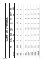
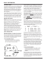
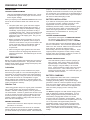
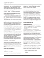
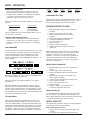
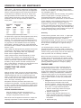
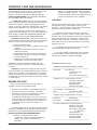
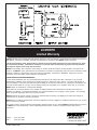
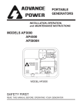
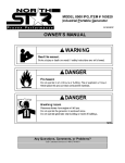
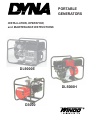
PORTABLE
GENERATORS
INSTALLATION, OPERATION,
and MAINTENANCE INSTRUCTIONS
DL9000E
DL5000H
D3000
Read and understand all instructions in the manual before starting and
operating the generator set.
USING THIS MANUAL
TABLE OF CONTENTS
Congratulations on your choice of a DYNA generator
set. You have selected a high-quality, precisionengineered generator set designed and tested to give you
years of satisfactory portable service.
To get the best performance from your new engine
generator set, it is important that you carefully read and
follow the operating instructions in this manual.
Should you experience a problem please follow the
“Things To Check” near the end of this manual. The
warranty listed in this manual describes what you can
expect from DYNA should you need service assistance
in the future.
INTRODUCTION
FEATURES BY MODEL
GUIDE TO PRODUCT SAFETY
BASIC INFORMATION
Intended Uses
Restricted Uses
Unit Capabilities
PREPARING THE UNIT
Unpacking the unit
Unit Preparation
Battery Installation
Battery Charging
Low Oil Level Shutdown System
LP/NG INSTALLATION
Installing the Fuel Line
Fuel Pressure
Tank Sizing
Changing Fuel Types
STARTING INSTRUCTIONS
Initial Starting
Starting
Starting Hints
Stopping And Storage
Operating Speed
Connecting The Loads
OPERATOR CARE AND MAINTENANCE
Engine Care
Generator Care
Cleaning
Troubleshooting - Things To Check BEFORE
You Call For Service
Schematic Wiring Diagram
WARRANTY
PROPER USE AND INSTALLATION
You must be sure your new engine generator set is:
* Properly serviced before starting
* Operated in a well ventilated area
* Operated so that exhaust gases are dispersed safely
* Wired by a qualified electrician
* Operated only for its designed purposes
* Used only by operators who understand its operation
* Properly maintained
COPY YOUR MODEL AND SERIAL
NUMBER HERE
No other DYNA generator has the same serial number as
yours. It is important that you record the number and
other vital information here. If you should ever need to
contact us on this unit it will help us to respond to your
needs faster.
MODEL______________________________________
SERIAL NUMBER _____________________________
PURCHASE DATE_____________________________
DEALER_____________________________________
Page i
i
1
2
3
3
3
4
4
4
4
5
5
6
6
6
6
7
7
7
7
8
8
9
9
9
10
10
60707-110
Page 1
DYNA SERIES 5/97
B&S STD
NO
PAGE 5
LOW OIL
SHUTDOWN
YES
PAGE 4
BATTERY
CHARGER
Note 1
2 QT
FUEL
TANK
SIZE
YES
120
VOLT
ONLY
NO
120/240
VOLT
NO
PAGE 4
ELECTRIC
START
NO
PAGE 5
LP/NG
FUEL
OPERATION
B&S STD
NO
NO
3 QT
YES
NO
NO
NO
HONDA
YES
NO
4 QT
YES
NO
NO
NO
B&S STD
NO
NO
4 QT
NO
YES
NO
NO
HONDA
YES
NO
6 QT
NO
YES
NO
NO
B&S GEN PRO
NO
NO
6 QT
NO
YES
NO
NO
B&S STD
YES
NO
4.5 GAL
NO
YES
NO
NO
B&S STD
YES
YES
4.5 GAL
NO
YES
YES
NO
HONDA
YES
NO
4.5 GAL
NO
YES
NO
NO
B&S STD
YES
NO
4.5 GAL
NO
YES
NO
NO
B&S STD
YES
YES
4.5 GAL
NO
YES
YES
NO
HONDA
YES
NO
4.5 GAL.
NO
YES
NO
NO
HONDA
YES
YES
4.5 GAL.
NO
YES
YES
NO
B&S VGD
YES
YES
4.5 GAL
NO
YES
YES
NO
B&S I/C
YES
YES
4.5 GAL
NO
YES
YES
YES
B&S VGD
YES
YES
4.5 GAL
NO
YES
YES
YES
NOTE 1: WITH THE EXCEPTION OF THE D1750 THESE BATTERY CHARGES ARE DESIGNED TO RECHARGE THE STARTING BATTERIES ONLY.
------------------------------------------------------------------------------------------------------------------------------------------------------------------------------------------------------------------------------------------------------------------------------------------------------------------------------------------------------------------------------------------------------------------------------------------------------------------------------
DL9000TFE
------------------------------------------------------------------------------------------------------------------------------------------------------------------------------------------------------------------------------------------------------------------------------------------------------------------------------------------------------------------------------------------------------------------------------------------------------------------------------
DL6000TFE
------------------------------------------------------------------------------------------------------------------------------------------------------------------------------------------------------------------------------------------------------------------------------------------------------------------------------------------------------------------------------------------------------------------------------------------------------------------------------
DL9000E
------------------------------------------------------------------------------------------------------------------------------------------------------------------------------------------------------------------------------------------------------------------------------------------------------------------------------------------------------------------------------------------------------------------------------------------------------------------------------
DL6000HE
------------------------------------------------------------------------------------------------------------------------------------------------------------------------------------------------------------------------------------------------------------------------------------------------------------------------------------------------------------------------------------------------------------------------------------------------------------------------------
DL6000H
------------------------------------------------------------------------------------------------------------------------------------------------------------------------------------------------------------------------------------------------------------------------------------------------------------------------------------------------------------------------------------------------------------------------------------------------------------------------------
DL6000E
------------------------------------------------------------------------------------------------------------------------------------------------------------------------------------------------------------------------------------------------------------------------------------------------------------------------------------------------------------------------------------------------------------------------------------------------------------------------------
DL6000
------------------------------------------------------------------------------------------------------------------------------------------------------------------------------------------------------------------------------------------------------------------------------------------------------------------------------------------------------------------------------------------------------------------------------------------------------------------------------
DL5000H
------------------------------------------------------------------------------------------------------------------------------------------------------------------------------------------------------------------------------------------------------------------------------------------------------------------------------------------------------------------------------------------------------------------------------------------------------------------------------
DL4500E
------------------------------------------------------------------------------------------------------------------------------------------------------------------------------------------------------------------------------------------------------------------------------------------------------------------------------------------------------------------------------------------------------------------------------------------------------------------------------
DL4500
------------------------------------------------------------------------------------------------------------------------------------------------------------------------------------------------------------------------------------------------------------------------------------------------------------------------------------------------------------------------------------------------------------------------------------------------------------------------------
D5500
------------------------------------------------------------------------------------------------------------------------------------------------------------------------------------------------------------------------------------------------------------------------------------------------------------------------------------------------------------------------------------------------------------------------------------------------------------------------------
D5000H
------------------------------------------------------------------------------------------------------------------------------------------------------------------------------------------------------------------------------------------------------------------------------------------------------------------------------------------------------------------------------------------------------------------------------------------------------------------------------
D4500
------------------------------------------------------------------------------------------------------------------------------------------------------------------------------------------------------------------------------------------------------------------------------------------------------------------------------------------------------------------------------------------------------------------------------------------------------------------------------
D3000H
------------------------------------------------------------------------------------------------------------------------------------------------------------------------------------------------------------------------------------------------------------------------------------------------------------------------------------------------------------------------------------------------------------------------------------------------------------------------------
D3000
------------------------------------------------------------------------------------------------------------------------------------------------------------------------------------------------------------------------------------------------------------------------------------------------------------------------------------------------------------------------------------------------------------------------------------------------------------------------------
D1750
MODEL
ENGINE
TYPE
FEATURES BY MODEL
GUIDE TO PRODUCT SAFETY
This engine generator set has been designed and
manufactured to allow safe, reliable performance. Poor
maintenance, improper or careless use can result in
potential deadly hazards; from electrical shock, exhaust gas
asphyxiation, or fire. Please read all safety instructions
carefully before installation or use. Keep these instructions
handy for future reference. Take special note and follow all
warnings on the unit labels and in the manuals.
3. DEADLY EXHAUST GAS - Exhaust fumes from any
gasoline engine contain carbon monoxide, an invisible,
odorless and deadly gas that must be mixed with fresh air.
a. Operate only in well ventilated areas.
b. Never operate indoors.
c. Never operate the unit in such a way as to allow
exhaust gases to seep back into closed rooms (i.e.
through windows, walls or floors).
ANSI SAFETY DEFINITIONS
______________________________________________________
DANGER:
DANGER indicates an imminently hazardous situation
which, if not avoided, will result in death or serious injury. This
signal word is to be limited to the most extreme situations.
______________________________________________________
______________________________________________________
WARNING:
WARNING indicates a potentially hazardous situation
which, if not avoided, could result in death or serious injury.
______________________________________________________
______________________________________________________
CAUTION:
CAUTION indicates a potentially hazardous situation which,
if not avoided, may result in minor or moderate injury. It may
also be used to alert against unsafe practices.
______________________________________________________
NOTE:
CAUTION is also used on the unit labels and in this manual
to indicate a situation that could result in serious damage or
destruction of the equipment and possible personal injury.
______________________________________________________
4. NOISE HAZARD - Excessive noise is not only tiring, but
continual exposure can lead to loss of hearing.
a. Use hearing protection equipment when working
around this equipment for long periods of time.
b. Keep your neighbors in mind when permanently
installing this equipment.
5. CLEANLINESS- Keep the generator and surrounding
area clean.
a. Remove all grease, ice, snow or materials that create
slippery conditions around the unit.
b. Remove any rags or other material that could create
potential fire hazards.
c. Carefully wipe up any gas or oil spills before starting
the unit.
d. Never allow leaves or other flammable material to
build up around the engine exhaust area.
6. SERVICING EQUIPMENT- All service, including the
installation or replacement of service parts, should be
performed only by a qualified technician.
1. ELECTRIC SHOCK- The output voltage present in this
equipment can cause a fatal electric shock. This equipment
must be operated by a responsible person.
a. Use only factory approved repair parts.
b. Do not work on this equipment when fatigued.
c. Never remove the protective guards, cover, or
receptacle panels while the engine is running.
d. Use extreme caution when working on electrical
components. High output voltages from this
equipment can cause serious injury or death.
e. Always avoid hot mufflers, exhaust manifolds, and
engine parts. They all can cause severe burns
instantly.
f. Installing a home-standby generator is not a “do-ityourself” project. Consult a qualified, licensed
electrician or contractor. The installation must comply
with all national, state, and local codes.
a. Do not allow anyone to operate the generator without
proper instruction.
b. Guard against electric shock.
c. Avoid contact with live terminals or receptacles.
d. Use extreme care if operating this unit in rain or snow.
e. Use only three-prong grounded plugs and extension
cords.
f. Be sure the unit is properly grounded to an external
ground rod driven into the earth.
2. FIRE HAZARD- Gasoline and other fuels always present a
hazard of possible explosion and/or fire.
a. Do not refuel when the engine is running or hot. Allow
the engine to cool at least two minutes before refueling.
b. Keep fuel containers out of reach of children.
c. Do not smoke or use open flame near the generator set
or fuel tank.
d. Keep a fire extinguisher nearby and know its proper
use. Fire extinguishers rated ABC by NFPA are
appropriate.
e. Store fuel only in an approved container, and only in a
well-ventilated area.
DYNA SERIES 5/97
Page 2
60707-110
BASIC INFORMATION
INTENDED USES
These engine generator sets have been designed primarily
for portable use. Both 120 and 240 volt AC receptacles are
provided in the 'control panel' to plug in your loads (lights,
portable tools, and small appliances). These units are
dual wound generators, therefore the 120 Volt loads must
be equally split with 1/2 of the rated capacity available on
each of the two 120 Volt circuits. See unit capabilities for
further explanation.
These portable units require large quantities of fresh air for
cooling of both the engine and the generator. Fresh air is
drawn from both the engine end and the generator end and
is exhausted at the center of the unit. For safety, long life
and adequate performance, these units should never be
run in small compartments without positive fresh air flow.
RESTRICTED USES
DO NOT remove from the cradle assembly. Removal of the
generator from the cradle assembly may cause excessive
vibration and damage to the engine generator set.
DO NOT install and operate these portable generators in a
small compartment., i.e. generator compartment of
vehicles, motor homes or travel trailers. These
compartments will not allow enough free flow fresh air to
reach the engine generator set for cooling and will cause
the unit to overheat damaging both the engine and the
generator. Small compartments will also develop hot
spots where there is very little air flow and may cause a fire.
Check the appliance or tool nameplates for the current and
voltage to insure compatibility. Remember that power taken
from receptacle C reduces the power available at both A and
B. Any remaining 120 volt loads should be equally divided
between A and B. Failure to split the load will cause
permanent damage to the stator. Although circuit breakers
are provided, damage due to overloading constitutes abuse
and will not be warranted. Refer to the generator nameplate
for your unit's capabilities.
Starting Electric Motors - Electric motors require much more
current (amps) to start them than to run them. Some motors,
particularly low cost split-phase motors, are very hard to start
and require 5 to 7 times as much current to start them as to
run them. Capacitor motors are easier to start and usually
require 2 to 4 times as much current to start them as to run
them. Repulsion Induction motors are the easiest to start
and usually require 1 1/2 to 2 1/2 times as much to start them
as to run them.
Most fractional horsepower motors take about the same
amount of current to run them whether they are of RepulsionInduction (RI), Capacitor (Cap), or Split-Phase (SP) type. The
chart below shows the approximate current required to start
and run various types and sizes of 120 volt 60 cycle electric
motors under average load conditions.
DO NOT attempt to operate at 50 cycles. These units are
designed and governed to operate at 60 Cycles only.
UNIT CAPABILITIES
Generator Connections - The diagram below represents a
typical 4000 watt generator. Receptacles A and B are the
two 120 Volt duplex receptacles. Up to 2000 watts at 120
volts (16.6 Amps) can be taken from the generator at each
of the receptacles. This generator produces 120 and 240
volt, 60 Hz (Hertz), AC (Alternating Current).
CAUTION: EQUIPMENT DAMAGE
CAUTION MUST BE EXERCISED TO PREVENT
OVERLOADING EITHER OF THE GENERATORS
120 VOLT OUTPUT CIRCUITS (A OR B).
HP
RUNNING
AMPS
1/6
1/4
1/3
1/2
1
3.2
4.5
5.2
7.2
13.0
SP
STARTING AMPS
CAP
16 TO 22
22 TO 32
26 TO 35
NOT MADE
NOT MADE
6 TO 13
9 TO 18
10 TO 21
14 TO 29
26 TO 52
RI
5 TO 8
7 TO 12
8 TO 17
11 TO 18
20 TO 33
The figures given above are for an average load such as a
blower or fan. If the electric motor is connected to a hard
starting load such as an air compressor, it will require more
starting current. If it is connected to a light load, or no load
such as a power saw, it will require less starting current. The
exact requirement will also vary with the brand or design of
the motor.
Self-excited generators respond to severe overloading
differently than the power line. When overloaded, the engine
is not able to supply enough power to bring the electric motor
up to operating speed. The generator responds with high
initial starting current, but the engine speed drops sharply.
The overload may stall the engine. If allowed to operate at
very low speeds, the electric motor starting winding will burn
out in a short time. The generator winding might also be
damaged.
CAUTION: EQUIPMENT DAMAGE
RUNNING THE GENERATOR SET UNDER THESE
CONDITIONS MAY RESULT IN DAMAGING THE
GENERATOR STATOR AS WELL AS THE MOTOR
WINDING.
Because the heavy surge of current required for starting
motors is required for only an instant, the generator will not
be damaged if it can bring the motor up to speed in a few
seconds of time. If difficulty is experienced in starting motors,
turn all other electrical loads off and if possible reduce the
load on the electric motor.
60707-110
Page 3
DYNA SERIES 5/97
PREPARING THE UNIT
substance will clog the carburetor and will not burn
properly. The use of a fuel additive, such as STA-BIL, or an
equivalent will minimize the formation of fuel gum deposits.
If a unit has been out of operation for an extended period of
time it is best to drain old fuel from the engine and replace
with fresh fuel before attempting to start.
UNPACKING
CAUTION: EQUIPMENT DAMAGE
THIS UNIT HAS BEEN SHIPPED WITHOUT OIL. Failure
to maintain the engine oil at the proper level will result in
serious engine damage.
BATTERY INSTALLATION
When you unpack your new ENGINE GENERATOR be sure to
remove all the information sheets and manuals from the
carton.
1. This power plant was in good order when shipped.
Inspect the power plant promptly after receiving it. If
damage is noted, notify the transportation company
immediately; request proper procedures for filing a
“concealed damage” claim. Title to the equipment and
responsibility for filing a claim rests with you when a
generator is sent F.O.B. shipping point. Only you can
legally file a claim.
2. Before proceeding with the preparation of your new
engine generator set for operation, take a couple of
minutes to insure that the unit you have received is the
correct model and review the specification pages in
this manual to insure that this unit fits your job
requirements.
If you intend to use the power plant’s electric start system,
you will need to purchase a battery to operate it. Units
equipped with a recoil or rope start will operate
satisfactorily without a battery. A twelve volt battery, group
U1 rated at 190 CCA or larger is recommended for this
electric start engine generator set. Follow the battery
manufacturer's recommendations for servicing and
charging prior to use. .
CAUTION: EQUIPMENT DAMAGE
These electric start engines are NEGATIVE GROUND.
Use extreme caution when connecting the battery.
Connect the NEGATIVE battery terminal to GROUND.
For your safety always connect the positive battery cable to
the “bat+” terminal first. Then connect the negative battery
cable to the “bat-” terminal. Make sure all connections are
clean and tight. Reverse the sequence when
disconnecting, disconnect the negative cable first. These
engines produce enough direct current to keep a battery
charged under normal operating conditions, but were not
intended to be used as a battery charger.
3. After removing the engine generator from the carton
locate and remove the shipping strap attached to the
generator shock mount. See attached tag for removal
instructions.
UNIT PREPARATION
WARNING: PERSONAL INJURY
Before your engine generator was shipped from our factory it
was fully checked for performance. The generator was load
tested to its full capacity, and the voltage and frequency were
carefully checked and adjusted.
Lead acid batteries produce explosive hydrogen gas
when charging. Keep sparks, flames, and burning
cigarettes away from the battery. Ventilate the area
when charging or using the battery in an enclosed
space. Lead acid batteries contain sulfuric acid, which
causes severe burns. If acid contacts eyes, skin or
clothing, flush well with water. For contact with eyes, get
immediate medical attention.
Lubrication
Before starting the engine, fill the crankcase to the proper
level with a good quality oil. The recommended grade of oil
and quantity of oil required is listed in the engine operator's
manual. The necessity of using the correct oil, and keeping
the crankcase full cannot be overemphasized. Engine
failures resulting from inadequate or improper lubricant are
considered abuse and are not covered by the generator or the
engine manufacturer's warranty.
Gasoline Fuel
When using gasoline always use a good grade of unleaded
fuel. Leaded gasoline may be used if unleaded is not
available. Gasoline containing alcohol, such as gasohol is
not recommended. However, if gasoline with alcohol is used,
it must not contain more than 10 percent Ethanol and must
be removed from the engine during storage. DO NOT use
gasoline containing methanol. Always insure that the fuel is
clean and free of all impurities.
WARNING: FIRE DANGER
Gasoline and its fumes are VERY explosive when proper
precautions are not taken.
Never use gasoline that has been stored for an extended
period of time as the fuel will lose it's volatile properties and
you will be left with only the varnish residue. This varnish like
DYNA SERIES 5/97
BATTERY CHARGING
Units equipped with electric start have a small flywheel
charger built into the engine flywheel assembly for
recharging the starting battery. This flywheel charger
generates a small AC current that passes through a diode
at the end of the charging lead to produce a DC charging
current of about 1 AMP. This circuit is not designed to be
used as a battery charging circuit to recharge dead
batteries.
The D1750 is equipped a 10 AMP 12VDC charging circuit
which is designed to recharge dead batteries. A set of
battery charging leads has been provided with the unit.
These battery charging leads consist of a 12V DC
connector lead wire and battery clip assemblies. There is
a mating connector mounted in the receptacle panel on the
unit. If the positive and negative battery leads are
accidentally shorted, or are incorrectly connected to the
battery, the automatic resetting DC circuit breaker in the
control panel will trip to protect the generator and the
battery. This breaker will reset automatically, restoring the
voltage.
Page 4
60707-110
BASIC OPERATION
The open circuit charging voltage as measured with DC
meter or a volt-ohm meter will read approximately seven
volts. The peak voltage will be over 16 volts in order to
charge the battery . When the charger is connected to a 12
volt battery the battery voltage will immediately increase
about 0.5 volts, showing that the battery is being charged. A
DC ammeter in series with the charger output will indicate a
current reading approximately equal to the DC nameplate
rating if the battery is discharged.
LOW OIL LEVEL SHUTDOWN SYSTEM
Briggs & Stratton powered generators - Some engine
generator sets come equipped standard with the Briggs &
Stratton OILGARD warning system.
This low oil warning system will automatically stop the
engine before the oil level reaches an operational danger
point. This feature is designed to prevent costly repairs and
downtime.
The OILGARD system uses a float in the engine crankcase
to sense the oil level. If a low oil level condition should occur
during operation, the float will ground out the magneto
impulse, “killing” the engine. In addition, there is an
indicator light mounted on the engine shroud near the recoil
starter. This light will blink on and off to indicate a low oil
level condition when you are attempting to start the unit. To
get the engine started, you must add the required amount of
oil to the engine crankcase.
Use of the OILGARD system on applications that are subject
to shock, bumping or severe angles of operation (in excess
of 15 degrees) should be avoided. This is especially true if
an unexpected shutdown would cause a safety hazard or
serious inconvenience for the operator.
Honda powered generators - These engine generator sets
come equipped standard with the Honda Oil Alert System.
The Oil Alert system is designed to prevent damage caused
by an insufficient amount of oil in the crankcase. Before the
oil level in the crankcase can fall below a safe limit, the Oil
Alert system will automatically shut down the engine (the
engine switch will remain in the ON position).
If the Oil Alert system shuts down the engine, the Oil Alert
lamp will flash when you attempt to start the engine and it
will not run. If this occurs, check the engine oil level.
LP/NG FUEL INSTALLATION
The information in this instruction is offered to assist you in
providing the proper vapor fuel supply for your engine. This
information is only provided to advise you of the engine’s
requirements and the decisions you must make. In no case
should this information be interpreted to conflict with any
local, state or national code. If in doubt, always follow local
codes.
DANGER: FIRE - PERSONAL INJURY All fuel lines must be installed by qualified fuel
supplier.
THESE UNITS INDOORS. The unit should be stored in a dry
location. During a power outage move the unit outdoors to a
flat dry location such as a driveway, concrete pad or
sidewalk for use. We recommend installing the optional
dolly kit or equivalent for ease of handling.
The fuel source should be as close as possible to the
outdoor operating location. This will reduce the installation
cost of fuel runs. Connect the fuel supply line to the inlet of
the fuel demand regulator on the unit using a locally
approved flexible fuel line (see table for recommended line
size). The pressure supplied to the demand regulator
must be FOUR TO SIX OUNCES or 7 to 11 INCHES W.C.
(water column). The primary regulator at the fuel supply
must be capable of delivering the proper volume of fuel at
this pressure.
Have your local fuel supplier install a protected fuel
connection at the outside operating location. He should
also install a lockable fuel shutoff valve at the connection
point. Have your fuel supplier permanently install a flexible
fuel line to the demand regulator on the engine generator
set.
INSTALLING THE FUEL LINE
DANGER: PERSONAL INJURY
Units that are intended to be run unattended MUST have
an electric fuel solenoid installed. This solenoid MUST
be wired to AUTOMATICALLY turn off the fuel whenever
the engine stops. See page 12 for additional
information.
Unit location will determine the size of fuel line that is
required to supply the engine with a constant fuel pressure.
Refer to the tables below for fuel line size, and
recommended tank size. For distances of 100 feet and over,
a two regulator fuel system consisting of a primary 10-15#
regulator at the tank and a 6 ounce secondary regulator
installed about 10 feet from the generator. You need to run a
3/4 inch line or larger from the secondary regulator to the
engine-generator set. When a two (2) stage regulator
system is used, a fuel line size of 3/8 inch is generally
adequate for distances up to 300 feet. The line size from the
table below applies to the distance from the second
regulator to the demand regulator. A positive fuel shut-off
device must be installed in the fuel line close to the engine
generator set. This may be either a lockable manual shutoff valve available from your local fuel installer, or a 12 volt
DC fuel solenoid valve. This optional 12 volt DC valve is
available through your local Winco dealer as part number
42942-000.
The fuel line used to connect the supply line to the demand
regulator must be a locally approved flexible fuel line.
Products used will vary in different regions depending on
availability and local codes. Consult with your local fuel
supplier to insure complete compliance with ALL codes.
1. Remove the pipe plug from the demand
regulator.
2. Connect the flex fuel line to the demand
regulator.
OPERATING LOCATION
The engine-generator models covered in this manual were
designed for portable use. DO NOT INSTALL OR OPERATE
60707-110
Page 5
DYNA SERIES 5/97
BASIC OPERATION
DANGER: PERSONAL INJURY
Do not use galvanized pipe in the fuel line runs. The
galvanized coating will become eroded and flake off,
causing possible obstruction or damage to the regulator
or fuel valve. The obstruction could cause an
inoperative engine or an explosive fuel leak.
Size of pipe required for generators operating on natural gas/
LP gas.
Length of Fuel Line
less than 25 feet
25 to 100 feet
over 100 feet
*allow an additional 3 feet for each
use ‘street ells’ (restrictive)
Fuel Line Size
3/4 inch black pipe
1 inch black pipe
not recommended
standard elbow. Do not
Temp
60 deg f.
DL6000TFE 40 gal
DL9000TFE 70 gal
0 deg f.
125 gal
200 gal
-20 deg f.
350 gal
700 gal
CHANGING FUEL TYPES
These engine generator sets are designed to run on three
different fuels; gasoline, natural gas or LP vapor. They
may be easily changed from one fuel to another.
FROM GASOLINE TO LP/NG
1. With the engine running turn off the gasoline
fuel valve.
2. Run the engine until it runs out of fuel.
3. Remove the pipe plug from the demand
regulator.
4. Install locally approved flexible fuel line.
5. Connect the LP/NG vapor fuel line.
6. Turn on the vapor fuel.
7. Start the engine.
8. Apply the load to the generator.
9. Adjust the fuel mixture valve to smooth the
engine out.
DANGER! - FIRE - PERSONAL INJURY Be careful when sealing gas joints. Excessive sealing
compound can be drawn into the solenoid, regulator or
carburetor causing an engine malfunction or dangerous
fuel leak.
FUEL PRESSURE
Correct fuel pressure cannot be stressed enough. The most
common cause for inoperative systems is an inadequate or
incorrect fuel pressure. Power and performance of the
engine is in direct relation to the correctness of the fuel
system. Shown below is a block diagram of a typical L.P. or
N.G. installation.
30 deg f.
50 gal
80 gal
Note: Operating on LP/NG vapor fuel for an extended
period of time without liquid fuel in the carburetor may
damage the carburetor float, and the needle seat
assembly. If you plan to convert back to gasoline, we
recommend the float and needle seat assembly be
removed from the carburetor. (Consult a local engine
supplier for assistance.)
FROM LP/NG TO GASOLINE
1. With the engine running turn off the LP/NG fuel
supply.
2. Run the engine until it runs out of fuel.
3. Remove the flexible fuel line from the demand
regulator.
4. Reinstall the pipe plug in the regulator. (use
thread sealant sparingly)
5. Check to be sure the gasoline fuel valve is off.
6. Fill the gasoline fuel tank.
7. Turn on the gasoline fuel valve.
8. Start the engine.
9. Adjust the load jet on the carburetor as
required to smooth the engine out.
Reference numbers 1 through 4 in the block diagrams above
are fuel lines supplied by customer.
Reference number 5 is already installed on your engine
generator set.
Remember that whichever fuel delivery system or type of
vapor fuel used, the fuel pressure at the demand regulator
installed on the engine generator must be between 4 and 6
oz. (7-11 inches of water column). Any lower pressure and
the unit will starve for fuel under load. Any higher and the unit
will ‘flood’ when attempting to start.
LP TANK SIZING
Once above the minimum acceptable size, the size of L.P.
tank used will generally depend on how long you want the
unit to run without refilling. The tank sizes shown below are
the smallest recommended tank sizes based on the outside
temperature. Keep in mind the colder it gets the slower L.P.
will vaporize. This is the reason for the larger tanks at low
temperature. Minimum sizing is not based on running time.
DYNA SERIES 5/97
Optional Dolly Kit
An optional dolly kit is available for this engine generator
set. The dolly kit comes with instructions and parts list.
After installing the dolly kit, file the instructions and parts list
in the back of this manual for future reference.
INITIAL START UP
Use the following checklist to verify the correct preparation
of the engine generator before starting.
Before Starting always Check:
1. Engine oil, fill as required with correct grade and
quantity.
2. Fuel level, fill as required with clean fresh fuel.
Page 6
60707-110
BASIC OPERATION
3. Automatic Idle is in the 'Off' position
4. Visually for loose parts.
STARTING HINTS
1. Cold weather
a. Use the proper oil for the temperature expected.
b. Use fresh winter grade fuel. Winter grade
gasoline is blended to improve starting. Do not
use summer gasoline.
c. A slightly richer fuel mixture will usually improve
cold starting.
STARTING
The throttle control on these generators is preset and locked
to operate at 3600 RPM (nominal) with no load speed set at
3750 RPM. Only a trained service technician should be
allowed to adjust this speed setting. See “Operating Speed”
section for additional information.
2. Hot weather
a. Use the proper oil for the temperature expected.
b. Use only summer blended gasoline. Using
gasoline left over from winter may cause the unit
to vapor lock.
c. DO NOT over-choke the unit.
NOTICE: ENGINE START LOCKOUT
This unit will not start if it is low on oil. The lubricating oil
level must be at the full mark before the engine will start.
MANUAL STARTING - Refer to the engine manual for
additional starting, operating, and stopping instructions.
NOTICE: TRI-FUEL STARTING
Tri-Fuel generators operating on vapor fuel, (either L.P. or
NG) must be started using the electric start system
provided. You cannot hand crank the unit fast enough to
develop the proper vacuum to make the vapor fuel system
work. In addition the demand regulator on the DL6000TFE
has a primer button, in the center of it, which must be
depressed, while engaging the starter. WHEN USING
VAPOR FUEL NEVER USE THE CHOKE. Use of the choke
will prevent the air and fuel from properly mixing.
STOPPING AND STORAGE
1. Depress the metal stop strip on top of the engine to
‘ground out’ the spark.
2. Before extended storage (over 30 days) certain
precautions must be taken to ensure the fuel doesn’t
deteriorate and clog the fuel system. Note: The use of
a fuel additive, such as STA-BIL, or an equivalent, will
minimize the formation of gum deposits during
storage. Such an additive may be added to gasoline
in the engine’s fuel tank or to gasoline in a storage
container.
1. Turn on the fuel supply.
2. Move the choke to the full "on" position. A warm engine
will require less choking than a cold engine.
3. Grasp starter grip and pull slowly until starter engages,
then pull cord rapidly to overcome compression,
prevent kickback and start the engine. Repeat if
necessary.
4. When the engine starts, open the choke gradually.
5. The engine should promptly come up to operating
speed.
Electric Starting - If the engine is cold and stiff or if the battery
is not fully charged, starting can be made easier by slowly
hand cranking the engine through the compression stroke
before pushing the starter switch. This permits the starter to
gain momentum before the heavy load of the compression
stroke occurs. This minimizes the drain on the battery and
improves the possibility of starting under such adverse
conditions. Always keep the battery charged, but especially
during cold weather operation.
1. Turn on the fuel supply.
2. Move the choke to the full "on" position. A warm
engine will require less choking than a cold engine.
3. Engage the engine start switch briefly to the START
position. The starter life is improved by using shorter
starting cycles with time to cool off between cranking
cycles. Do not operate the starter more than 15
seconds during each minute. Repeat if necessary.
4. When the engine starts, open the choke gradually.
5. The engine should promptly come up to operating
speed.
CAUTION: EQUIPMENT DAMAGE
Never permit the choke to remain on after the engine has
run for a short time. It is not necessary to choke the
engine when it is warm. Avoid over-choking.
60707-110
a. Remove the remaining fuel from the fuel tank.
b. Start the engine and allow it to run until all
the fuel in the carburetor and the fuel lines has
been used up and the engine stops.
c. While the engine is warm, drain the oil and
refill with fresh oil.
d. Remove the spark plug, pour approximately
1/2 ounce (15 cc) of engine oil into the cylinder
and crank slowly to distribute oil. Replace spark
plug.
e. Clean dirt and chaff from cylinder, cylinder
head fins, blower housing, rotating screen and
muffler areas.
f. Store in a clean and dry area.
OPERATING SPEED
The engine-generator must be run at the correct speed in
order to produce the proper electrical voltage and frequency.
CAUTION: EQUIPMENT DAMAGE
The output voltage should be checked to insure the
generator is working properly prior to connecting a load
to the generator. Failure to do so could result in damage
to equipment plugged into the unit and possible injury to
the individual.
All engines have a tendency to slow down when a load is
applied. When the electrical load is connected to the
generator, the engine is more heavily loaded, and as a
result the speed drops slightly. This slight decrease in
speed, together with the voltage drop within the generator
itself, results in a slightly lower voltage when the generator
is loaded to its full capacity than when running no load. The
Page 7
DYNA SERIES 5/97
OPERATOR CARE AND MAINTENANCE
slight variation in speed also affects the frequency of the
output current. This frequency variation has no appreciable
effect in the operation of motors, lights and most appliances.
However, electronic equipment and clocks will be affected if
correct RPM is not maintained. See Load vs. Output chart.
When in doubt consult the manufacturer or a local
electrician. The nameplate amperage rating for electric
motors can be misleading. See “Starting Electric Motors” in
Unit Capabilities (page 3).
These engine generator sets are inherently self regulating
based on engine speed. The engine governor will
automatically adjust itself to the load. No harm to the
generator will result if it is operated with no load connected.
Although individual units and models may vary slightly, the
normal voltage and frequency of the engine-generators
described in this book are approximately as follows, under
varying loads:
LOAD vs. OUTPUT
__________________________________________________________________________________________________________________
Generator
Frequency
Load
Speed
Applied*
(RPM)
(Hz)
Voltage
120V
Recpt.
__________________________________________________________________________________________________________________
None
Half
Full
3750
3600
3540
62.5
60.0
59.0
129V
120V
115V
Proper utilization of the receptacles located on the control
panel is necessary to prevent damage to either the
receptacles or the generator. The generator is a limited
source of electrical power, therefore pay special attention to
the receptacle and generator ratings. The nameplate rating
can be obtained through a single receptacle as long as the
receptacle amperage rating is not exceeded.
Grounding
__________________________________________________________________________________________________________________
*Portion of plant’s rated output current.
The speed of the engine was carefully adjusted at the factory
so that the generator produces the proper voltage and
frequency. For normal usage, the speed setting should not
be changed. If the generator is being run continuously on a
very light load, it is often advisable to lower the operating
speed slightly. Whenever making any speed adjustments
check the unit with a voltmeter or tachometer and be sure the
speed is correct.
Lower voltage may damage both the generator and any load
connected to it. Running the engine at excessively high
speeds results in high voltage, which may significantly
shorten the life of appliances being used.
All units must be grounded. Drive a 3/4 or 1" copper pipe
or rod into the ground close to the engine-generator set.
The pipe must penetrate moist earth. Connect an
approved ground clamp, to the pipe. Run a no. 10 Awg wire
from clamp to the generator ground lug on the “end cover”.
Do not connect to a water pipe or to a ground used by a
radio system.
The engine-generators covered in this manual were
designed for portable use. Do NOT install or operate this
generator indoors. The unit should be stored in a warm dry
location. During a power outage, move the unit outdoors to
a flat dry location such as a driveway or sidewalk.
Output voltage should be checked periodically to ensure
continued proper operation of the generating plant and
appliances. If the generator is not equipped with a voltmeter,
it can be checked with a portable meter. Frequency can be
checked by using an electric clock with a sweep second
hand. Timed against a wrist watch or a stop watch the clock
should be correct within +/- 2 seconds per minute.
Many homes today are wired for at least 60 to 100 Amp
entrance service, much greater than the capacity of these
portable generators. Do not attempt to power a home with
this portable generator. This generator set is suitable for
powering individual appliances or emergency lighting.
CONNECTING THE LOADS
If major engine service or repair is required contact an
authorized engine service center. The manufacturer of
these engines has established an excellent world-wide
engine service organization. Engine service is very likely
available from a nearby authorized dealer or distributor.
Check the yellow pages of your local telephone directory
under “Engines-Gasoline” for the closest engine repair
center or ask the dealer from whom you purchased the
power plant.
Applying The Load
Allow the engine to warm up for two or three minutes before
applying any load. This will allow the engine to reach normal
operating temperature and oil to circulate throughout the
engine. A short warm-up time will permit the engine to work
more efficiently when the load is applied and will reduce the
wear in the engine, extending its life.
ENGINE CARE
1. Change the oil after the first five hours of operation
and every 50 hours thereafter under normal
operating conditions. Change engine oil every 25
hours of operation if the engine is operated under
heavy load, or in high ambient temperatures.
Receptacles have been provided to allow loads to be
connected to the generator. The loads should be added one
at a time. If a large motor is being started or multiple motors
are being started, they should be started individually and the
largest should be started first.
a. Remove oil drain plug at base of the engine
and drain the oil with the engine warm.
b. Replace oil drain plug.
c. Remove oil filler plug and refill with new oil.
Refer to the table in the engine manual for the
proper grade of oil based on your operating
temperature.
d. Replace filler plug.
CAUTION: EQUIPMENT OVERLOAD
Keep the generator load within the generator and
receptacle nameplate rating. Overloading may cause
damage to the generator and/or the loads .
Most electric tools and appliances will have the voltage and
amperage requirements on their individual nameplates.
DYNA SERIES 5/97
Page 8
60707-110
OPERATOR CARE AND MAINTENANCE
b. Receptacles - Quality receptacles have been
utilized. If a receptacle should become cracked or
otherwise damaged, replace it. Using damaged or
cracked receptacles can be both dangerous to the
operator and destructive to the equipment.
2. Checking the Oil Level: The oil level must always be
checked before the engine is started. Take care to remove
any dirt or debris from around the oil fill plug before
removing. Be sure the oil level is maintained. FILL TO
POINT OF OVERFLOWING or on units with the extended oil
fill to the “FULL” mark on the dipstick.
3. Cartridge Air Cleaner - Remove and clean cartridge
yearly or after every 25 hours, whichever occurs first. Service
more often if necessary. Clean by tapping gently on flat
surface. If very dirty, replace the cartridge using only original
equipment parts available at any engine service center.
Do not use petroleum solvents, such as kerosene, to
attempt to clean the cartridge. They may cause deterioration
of the cartridge. DO NOT OIL CARTRIDGE, DO NOT USE
PRESSURIZED AIR TO CLEAN OR DRY CARTRIDGE.
4. Dual Element Air Cleaner - Clean and re-oil foam precleaner at three month intervals or every 25 hours, whichever
occurs first. Service more often under dusty conditions.
a. Remove knob and cover.
b. Remove foam pre-cleaner by sliding it off the paper
cartridge.
c. Wash foam pre-cleaner in kerosene or liquid
detergent and water
d. Wrap foam pre-cleaner in cloth and squeeze dry.
e. Saturate foam pre-cleaner in engine oil. Squeeze
to remove excess oil.
f. Install foam pre-cleaner over paper cartridge.
Reassemble cover and screw down tight.
Replace the cartridge included with Dual Element Air
Cleaner yearly or every 100 hours. Service more often if
necessary.
5. Spark Plug - Clean and reset gap at .030" every 100
hours of operation. Do not blast clean spark plug. Clean by
scraping or wire brushing and washing with a commercial
solvent. Poor spark will occur if terminal does not fit firmly
on spark plug. If this happens reform the terminal to fit firmly
on spark plug tip.
GENERATOR CARE
Proper care and maintenance of the generator is
necessary to insure a long trouble free life.
1. Exercising The Generator - The generator should be
operated every three to four weeks. It should be
operated for a period of time sufficient to warm the
unit up and to dry out any moisture that has
accumulated in the windings. If left, this moisture can
cause corrosion in the winding. Frequent operation of
the engine generator set will also insure that the set
is operating properly should it be needed in an
emergency.
2. Generator Maintenance - Any major generator service
including the installation or replacement of parts should be
performed only by a qualified electrical service technician.
USE ONLY FACTORY APPROVED REPAIR PARTS.
a. Bearing - The bearing used in these
generators is a heavy duty double sealed ball
bearing. They require no maintenance or
lubrication.
60707-110
CLEANING
Remove dirt and debris with a cloth or brush. DO NOT use
high pressure spray to clean either the engine or the
generator. This high pressure spray could contaminate the
fuel system and the generator components.
1. Keep the air inlet screen on both the engine and
generator free of any dirt or debris to insure proper cooling.
At least yearly remove the blower housing on the engine and
clean the chaff and dirt out of the engine cooling fins and
flywheel. Clean more often if necessary. Failure to keep
these areas clean may cause overheating and permanent
damage to the unit.
2. Periodically clean muffler area to remove all grass,
dirt and combustible debris to prevent a fire.
3. On engine mufflers equipped with spark arresters,
the spark arrester must be removed every 50 hours for
cleaning and inspection. Replace if damaged.
TROUBLESHOOTING HINTS
PROBLEM (SYMPTOMS) POSSIBLE CAUSES
——————————————————————————
Won’t Start
*Low Oil Level.
*Fouled spark plug.
*Out of fuel.
*Stop switch in stop position.
——————————————————————————
Voltage too low *Engine speed is too low.
*Generator overloaded.
*Defective rectifier.
*Defective stator.
*Defective rotor (field).
——————————————————————————
Circuit Breaker *Defective load.
Trips
*Defective receptacle.
——————————————————————————
Voltage too high *Engine speed is too high.
——————————————————————————
Generator
*Overloaded.
overheating
*Insufficient ventilation.
——————————————————————————
No output voltage*Short in load (disconnect).
*Broken or loose wire.
*Defective receptacle.
*No residual magnetism
(in generator).
*Defective stator.
*Defective rotor (field).
*Shorted capacitor.
*Defective rectifier.
——————————————————————————
Page 9
DYNA SERIES 5/97
24 MONTH
Limited Warranty
WINCO warrants to the original purchaser that the alternator is free from defects in workmanship and material for a period of
two years*, provided it is installed, operated and maintained in accordance with WINCO written instructions.
*NOTE: Units used for rental, demonstrations, commercial or prime power applications such as construction or utility,
are warranted for 90 days. Units that are resold are not covered under this warranty. Any further warranty, whether
expressed or implied, rests solely with the reseller.
WINCO’s sole liability, and Purchaser’s sole remedy for a failure under this warranty, shall be limited to the repair of the
product. At WINCO’s option, material found to be defective in material or workmanship under normal use and service will be
repaired or replaced. This warranty does not include circuit breakers, receptacles or ENGINES. Engines are covered
exclusively by the warranties of their respective manufacturers.
THERE IS NO OTHER EXPRESS WARRANTY.
To the extent permitted by law, any and all warranties are limited to 24 months from date of purchase. The user shall
determine the suitability of the product for its intended use prior to placing the unit in service. The user shall assume all
risks and liability in connection with determining the suitability of the unit for its particular use. Neither the manufacturer nor
the seller shall be liable for any injury, loss or damage arising out of improper use or operation of this unit. In no event is
WINCO liable for incidental or consequential damages.
Some states do not allow limitation on the duration of implied warranty and some states do not allow the exclusion or
limitation of incidental or consequential damages, so the above limitations may not apply in every instance. This warranty
gives you specific legal rights which may vary state to state.
WINCO reserves the right to change or improve its products without incurring any obligations to make such changes or
improvements on products previously purchased.
WINCO does not warrant products which have been subjected to misuse, negligence, modified or altered in any way or have
been involved in an accident.
For warranty service, return the product, transportation charges prepaid, to your nearest WINCO Authorized Service Center or
to WINCO at Le Center Minnesota. When requesting warranty service, evidence of original purchase date must be
presented.
Phone
FAX -
-
(507) 357-6831
(507) 357-4857
DYNA SERIES 5/97
225 S. Cordova Ave.
LeCenter, Mn 56057-1805
P/N 60707-110