1
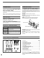
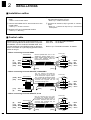
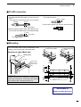
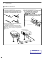
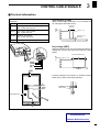
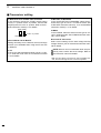
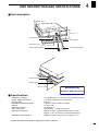
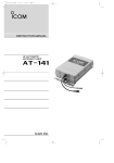
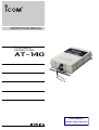
INSTRUCTION MANUAL
HF AUTOMATIC
ANTENNA TUNER
AT-140
Downloaded by
Amateur Radio Directory
FOREWORD
PRECAUTIONS
Thank you for purchasing the
AT-140 HF AUTOMATIC ANTENNA TUNER.
R DANGER HIGH VOLTAGE! NEVER touch
The AT-140 is designed, primarily for use with Icom HF
transceivers.
the antenna terminal, ground terminal, antenna or
counterpoise while transmitting. Place the AT-140, antenna and counterpoise in positions where no one can
touch them.
Refer to your HF transceiver instruction manual for operation. If you have any questions, contact your dealer.
NEVER use without a ground connection.
NEVER transmit during internal adjustment. This may
cause an electric shock.
IMPORTANT
USE the ground terminal for ground connection.
The mounting plate is not connected internally.
READ ALL INSTRUCTIONS carefully and completely before using the AT-140.
SAVE THIS INSTRUCTION MANUAL. This instruction manual contains important safety and installation instructions.
Ground terminal
EXPLICIT DEFINITIONS
Mounting plate
Word
Definition
Personal injury, fire hazard or electric
R WARNING
shock may occur.
CAUTION
NOTE
DO NOT operate your HF marine transceiver without
Equipment damage may occur.
running the boat’s engine.
If disregarded, inconvenience only. No
personal injury, fire hazard or electric
shock.
AVOID using the AT-140 in areas where the temperature is below –30°C (–22°F) or above +60°C
(+140°F).
SUPPLIED ACCESSORIES
The following accessories are supplied with the AT-140.
q
u
w
i
e
r
t
o
y
!2
!0
Qty.
q U-bolts ………………………………………………2
w U-bolt plates …………………………………………2
e Flat washers (M6 large) ……………………………8
r Flat washers (M6 small) ……………………………4
t Spring washers (M6) ………………………………8
y Nuts (M6) ……………………………………………8
u Hex head bolts (M6×50) ……………………………4
i Self-tapping screws (A0 6×30) ……………………4
o Weatherproof cap……………………………………1
!0 6-pin connector………………………………………1
!1 Connector pins ………………………………………4
!2 Ground cable (OPC-412) …………………………1
!1
Icom, Icom Inc. and the
are registered trademarks of
Icom Incorporated (Japan) in the United States, the United
Kingdom, Germany, France, Spain, Russia and/or other
countries.
i
MISCELLANEOUS ITEMS
TABLE OF CONTENTS
The following parts are additionally required for installation, but are not supplied with the AT-140.
Purchase these parts locally.
FOREWORD …………………………………………… i
q AWG 14×4-conductor shielded cable
*Icom offers an optional OPC-1147 CONTROL CABLE.
Length: 10 m; 32.8 feet
w 50 Ω coaxial cable
e PL-259 connectors
IMPORTANT …………………………………………… i
EXPLICIT DEFINITIONS ……………………………… i
PRECAUTIONS ……………………………………… i
SUPPLIED ACCESSORIES ………………………… i
MISCELLANEOUS ITEMS ………………………… ii
FEATURES …………………………………………… ii
FEATURES
Matches all bands
The AT-140 matches any frequency on every HF marine band. For example, the tuner matches a 7 m; 23 ft
long-wire antenna across 1.6–30 MHz.
Full automatic tuning
Just push the [TUNE] switch on the transceiver, and
the AT-140 adjusts immediately to the minimum SWR
of any frequency on any HF marine band.
HF operation on any size ship
The AT-140 allows you HF operation where antenna
element length is restricted due to space.
Weather resistant
The AT-140 is housed in a durable, completely weather
resistant ASA case with a rubber gasket. The antenna
tuner can be conveniently installed both on the deck or
in the cabin near the antenna element.
Simple installation
Installation is simple. Just connect the control and antenna cables. You never need to open the cover.
TABLE OF CONTENTS ……………………………… ii
1 ANTENNA SYSTEM …………………………… 1–2
■ Antenna for ship ………………………………… 1
■ Antenna for land operation ……………………… 1
■ Coaxial cable …………………………………… 2
■ Ground and counterpoise ……………………… 2
2 INSTALLATIONS ………………………………… 3–5
■ lnstallation outline………………………………… 3
■ Control cable……………………………………… 3
■ PL-259 connector………………………………… 4
■ Mounting ………………………………………… 4
■ Cable connections ……………………………… 5
3 CONTROL CABLE SIGNALS ………………… 6–7
■ Terminal information …………………………… 6
■ Transceiver setting ……………………………… 7
4 UNIT DESCRIPTION AND SPECIFICATIONS
………………………………………………………… 8
■ Unit description…………………………………… 8
■ Specifications …………………………………… 8
45 memories for shorter tuning time
To decrease the tune-up time, the AT-140 automatically
stores the matching conditions for up to 45 frequencies.
Re-tuning for a memorized frequency takes approx. 1
sec.
Super capacitor for memory backup
Even if the AT-140 is not used for approx. 1 week, the
built-in super capacitor backs up contents of the 45
memories.
Low power tune up
The AT-140 emits low output power during tuning. This
feature reduces the possibility of causing interference
to other stations.
Tuner through function
The tuner through function is built into the AT-140. This
function helps improve receiver gain, depending on the
antenna element length used, and operating frequency.
ii
1
ANTENNA SYSTEM
■ Antenna for ship
Required antenna element length
Required antenna element length to achieve full performance varies according to the lowest frequency:
The lowest frequency Required antenna element length
1.6 MHz band
7 m; 23.0 feet or longer
4 MHz band
3 m; 9.8 feet or longer
Insulator
Backstay operates as
a long-wire antenna.
The longer the antenna element, the better the antenna efficiency.
Undesirable antenna element lengths
AVOID multiples of 1⁄2λ (half wavelength) for an-
Insulator
tenna element lengths, since tuning becomes difficult.
L : Antenna element length to be avoided [m]
f : Operating frequency [MHz]
n : Natural number (n = 1, 2, 3, ...)
L=
300
1
×
× n
2
f
Whip antenna
[Example]
At an operating frequency of 16 MHz, avoid the following antenna element lengths:
L=
300
1
×
× n
2
16
1m
39 inches
9.4, 18.8, ...
For example, if 15 m is selected for an antenna element length, you have no problem in the 1.6–25 MHz
marine bands range.
NOTE: Keep antennas as far away from other objects
as possible, especially metal objects.
■ Antenna for land operation
In some countries, HF transceivers can be used for
land mobile operation. Ask your Icom Dealer for details, since the radio law varies according to each
country.
For land mobile operation on 4 MHz and above, an
optional AH-2b ANTENNA ELEMENT is available.
The AH-2b includes a sturdy tow hook mount system
for holding a 2.5 m; 8.2 feet stainless steel antenna
element plus all the necessary hardware.
AH-2b
1
Refer to the AH-2b instruction manual for the AH-2b
and AT-140 installation to your vehicle. Ask your Icom
Dealer for details.
Connect a suitable antenna element for a base station. To achieve full performance, refer to “Required
antenna element length” above.
ANTENNA SYSTEM
1
■ Coaxial cable
Insulate the lead-in cable of the AT-140 antenna terminal and antenna element from other metal objects.
To prevent erroneous indications, keep cables as far
away as possible from the flux gate compass.
To prevent interference, keep cables as far as possible from an antenna, electric pump and other electronic equipment.
Use suitable noise filters for alternators, fluorescent
lights, etc. Ask your Dealer for details.
■ Ground and counterpoise
Why a ship’s ground is required
The AT-140’s ground terminal MUST be connected
to your ship’s ground. Grounding prevents electric
shocks, interference to other equipment and other
problems. Grounding also ensures effective signal
transmission.
Counterpoise
If your ship is made of FRP, etc. and a good ship’s
ground is not available, connect a counterpoise.
1⁄4λ
radial for
each band
Ground terminal
DANGER! NEVER connect the ground terminal to
the following points. These connections may cause
an explosion or electric shocks:
– Gas or electrical pipe
– Fuel tank or oil-catch pan
IMPORTANT! The mounting plate is NOT connected to the AT-140’s internal ground.
Ideal ground points
One of following points is ideal:
– External ground plate
– External copper screen
– External copper foil
AT-140
1⁄4λ
(quarter wavelength) radial for each band is suitable for a counterpoise. Install the counterpoise directly below the AT-140’s ground terminal. Insulate
the ends of each radial from other metal objects. Layout the radial horizontally and as straight as possible.
L : Counterpoise length for the operating frequency [m]
f : Operating frequency [MHz]
Good ground points
If electrically connected to sea water, one of the following points is usable:
– Stainless steel stanchion
– Through mast
– Through hull
– Metal water tank
Undesirable ground points
AVOID the following points, if possible. These connections may cause noise or electrolysis:
– Engine block
– Ship’s DC battery ground
Electrolysis
All ground cables from the AT-140, HF transceiver,
etc. on your ship should be connected to only 1 ship’s
ground.
AVOID connection to 2 or more points. Voltage difference between 2 or more ship’s grounds may cause
electrolysis.
AVOID connection between dissimilar metals where
an electric current is present. These connections may
cause electrolysis.
L=
300
1
×
f
4
[Example]
At an operating frequency of 16 MHz, use a counterpoise with the following length:
L=
1m
300
1
×
16
4
4.7 [m]
39 inches
Ground cable
For best results, use the heaviest gauge wire or metal
strap available. Make the distance between the AT140’s ground terminal and ship’s ground as short as
possible.
Supplied ground cable can be used for ground connection to a through mast. Confirm that the through
mast is electrically connected to sea water.
R WARNING!— When grounding to metal hull
Use a Zinc anode to protect the hull from electrolysis.
Ask your technical dealer, installer or refer to a technical book, etc., for RF ground details.
2
2
INSTALLATIONS
■ Installation outline
q Connect a control cable and 4-conductor shielded
cable.
r Connect the control cable and the coaxial between
the transceiver and the AT-140.
• Refer to “Control cable” below.
• Refer to p. 5 “Cable connections.”
w Connect and solder the PL-259 connector to the
coaxial cable.
t Connect an antenna, ship’s ground or counterpoise.
• Refer to p. 1 “Antenna for ship” and p. 2 “Ground and
counterpoise.”
• Refer to p. 4 “PL-259 connector.”
e Mount the AT-140 in the desired location.
• Refer to p. 4 “Mounting.”
■ Control cable
Between the AT-140 and HF marine transceiver, connect 4 control signal lines as shown below. To prevent
RF feedback, use a 4-conductor shielded cable. Connect the shield line to the [GND] terminal on the transceiver. Icom offers 10 m (32.8 ft) long optional control
cables as at right.
OPC-566
OPC-1147
: for IC-M710/RT, M700PRO
: for IC-M802
Refer to p. 6 “Terminal information” for details.
D When connecting to Icom IC-M802
To transceiver
[E]
[13.6]
[STAR]
[KEY]
:
:
:
:
Black
Red
White
Green
To AT-140
Use the optional OPC-1147, or assemble the desired length 4-conductor shielded cable and the connector kits supplied with the
transceiver and the tuner.
[GND]
[E]
[13.6]
[STAR]
[KEY]
:
:
:
:
Black
Red
White
Green
[E]
[13.6]
[STAR]
[KEY]
:
:
:
:
Black
Red
White
Green
[E]
[13.6]
[STAR]
[KEY]
:
:
:
:
Black
Red
White
Green
[GND]
D When connecting to Icom IC-M710/RT, IC-M700PRO
[STAR] : White
[KEY] : Green
[13.6]
[E]
To transceiver
: Red
: Black
Use the optional OPC-566/1147
(either the connector to the AT-140
or the transceiver requires assembly), or assemble the desired length
4-conductor shielded cable and the
connector kits supplied with the
transceiver and the tuner.
[GND]
To AT-140
[GND]
D When connecting to Icom IC-M700/TY, IC-78
To transceiver
[E]
[13.6]
[STAR]
[KEY]
:
:
:
:
Black
Red
White
Green
Use the optional OPC-1147 (this
connector only requires assembly),
or assemble the desired length 4conductor shielded cable and the
connector kits supplied with the
transceiver and the tuner.
[GND]
3
[GND]
To AT-140
INSTALLATIONS
2
■ PL-259 connector
q Slide the coupling ring over the coaxial cable. Strip
the cable jacket and pull back to reveal 10 mm of
braid.
e Slide the connector body over the cable and solder as shown below.
Solder Solder
• Soft solder the exposed braid and then pull out the jacket.
Coupling
30 mm
r Screw the coupling ring onto the connector body.
10 mm (soft solder)
w Strip the cable as shown below. Soft solder the center conductor the entire length of the exposed braid.
10 mm
10 mm
3⁄8
1–2 mm
soft solder
inches
■ Mounting
Attach the AT-140 either horizontally or vertically with
one of the water drains facing downwards. After
mounting, remove the screw in the water drain.
Mounting on a flat surface
Using nuts and bolts
Using self-tapping
screws
Mounting on a Mast/Metal pole
Mast/
Using
Metal pole
U-bolt
U-bolts
U-bolt plate
Flat washer(L)
Spring washer
Flat washer(S)
Nut
Nut
Flat
washer(S)
Spring
washer
Flat
washer(L)
WARNING: Mount the AT-140 securely with the
supplied nuts and bolts. Otherwise, vibrations and
shocks due to waves, etc. could loosen the antenna
tuner making if fall, causing personal injury.
Flat
washer(L)
Hex head
bolt
Weatherproof cap
Drill a hole here
Diameter:7–8 mm; 9⁄32–5⁄16 inches
Downloaded by
Amateur Radio Directory
4
2
INSTALLATIONS
■ Cable connections
q Connect the coaxial cable and the control cable to
the AT-140 as illustrated below.
w Cover both the antenna and the control cable connectors with rubber vulcanizing tape and fix it with
a vinyl tape to prevent water seeping into the connector.
r Connect the coaxial cable and the control cable to
the transceiver as illustrated below.
t Ground the transceiver, AT-140 and shield cable of
the control cable via the ground terminal.
• See pgs. 2 and 7–10 for grounding details.
IMPORTANT!— AT-140
NEVER ground the AT140 via the mounting
plate. It is not connected to ground internally.
Rubber vulcanizing tape
Ground terminal
e Fix both of the coaxial and control cables to protect the inside connections.
Mounting plate
DO NOT pull the antenna and control cable receptacles. This may cause disconnection (in the
AT-140), internal connector damaged or bad
connection.
Icom HF transceiver
AT-140
Ground
Ground
(10
-1147
.8 ft)
m; 32
OPC
Downloaded by
Amateur Radio Directory
5
CONTROL CABLE SIGNALS
3
■ Terminal information
Consider the following points when using a non-Icom
transceiver.
Terminal
Description
[KEY]
Key voltage. Grounded during tuning.
Max. current drain 100 mA.
[13.6]
13.6 V DC + input terminal.
Max. current drain 2 A
[STAR]
[E]
Start voltage [STAR]
When a start voltage (less than 1 V) is received, the
AT-140 begins automatic tuning.
More than
350 msec.*
Start
voltage 8
[V]
6
Approx. 7.5 V
4
Receives start voltage.
Max. current drain 1 mA
Less than 1 V to
start tuning
2
0
Ground terminal for above signals.
Time
*For tuner through operation; Less than 250 msec.
Key voltage [KEY]
During automatic tuning, the AT-140 grounds the key
voltage line, and the HF transceiver reduces output
power.
During automatic tuning
Key
voltage 8
[V]
6
[KEY]
[STAR]
[13.6]
[E]
Approx. 7.5 V
4
2
0
Grounded
Time
If the key voltage is more than 8 V, switch the mode
switch (S1) to OFF mode (lower position).
[E]
[13.6]
[STAR]
[KEY]
S1
NORMAL mode
OFF mode
Mode switch (S1)
Downloaded by
Amateur Radio Directory
6
3
CONTROL CABLE SIGNALS
■ Transceiver setting
IC-M700 with serial number 2500 and below
In the IC-M700, change the [TUNE] switch setting
from the “1” position to the “2” position. Confirm that
the [KEY] switch is in the “2” position. Refer to the ICM700 instruction manual p. 9 for details.
[KEY] [TUNE]
Confirm “2” position.
Select “2” position.
Other IC-M700 and IC-M700TY
Nothing necessary to set. However, the tuner through
function is not available when using the AT-140 with
IC-M700/TY.
IC-78
In the IC-78, select the antenna tuner type as “4* (AH4)” in initial set mode. See IC-78 instruction manual
p. 32 for details.
IC-M710/RT, IC-M700PRO
In the IC-M710/RT and IC-M700PRO, select the antenna tuner type as “AH-3*” in initial set mode. See
IC-M710/RT instruction manual p. 13 or IC-M700PRO
instruction manual p. 11 for details.
IC-M802
In the IC-M802, select the antenna tuner type as “AT140” in initial set mode. See IC-M802 instruction manual p. 49 for details.
Non-Icom HF transceiver
Select correct settings for the start voltage and key
voltage. Refer to your HF transceiver instruction manual for details.
NOTE: When a non-Icom automatic tuner was previously used, confirm the tuner settings. Refer to
the instruction manual for details.
*With “AT-130” setting, use of the AT-140 is possible, however, the tuner through function cannot be operated.
7
UNIT DESCRIPTION AND SPECIFICATIONS
4
■ Unit description
340 mm; 13.4 in
230 mm; 9.1
in
80 mm; 3.1 in
Ground terminal
Mounting plate
Water drain screw
Antenna cable receptacle
Control cable receptacle
Antenna terminal
Mounting plate
91.5 mm; 3.6 in
Downloaded by
Amateur Radio Directory
■ Specifications
• Frequency coverage
• Power supply requirement
• Current drain
• Operating temperature range
• Weight
• Antenna connector
• Max. Input power
• Automatic tuning time
• Automatic tuning accuracy
: 1.6–30 MHz (with 7 m; 23.0 feet or longer antenna element)
: 13.6 V DC (supplied from HF transceiver)
: Max. 2 A
: –30°C to +60°C (–22°F to +140°F)
: 2.5 kg; 5.5 lb
: SO-239 (50 Ω)
: 150 W (PEP) 100 W (continuous)
: Approx. 2–3 sec. (general condition) Max. 15 sec.
Approx. 1 sec. (re-tuning for a memorized frequency)
: SWR 2.0:1 (after tuning, except for multiples of 1⁄2 λ)
All stated specifications are subject to change without notice or obligation.
8
Icom America Inc.
Icom (Europe) GmbH
<Corporate Headquarters>
2380 116th Avenue N.E., Bellevue, WA 98004, U.S.A.
Phone: (425) 454-8155 Fax: (425) 454-7619
URL: http//www.icomamerica.com
Communication Equipment
Himmelgeister Str. 100,
D-40255 Düsseldorf, Germany
Phone: 0211 346047
Fax: 0211 333639
URL: http//www.icomeurope.com
<Customer service>
Phone: (425) 454-7619
Icom Canada
Icom Spain S.L.
Glenwood Centre #150-6165 Highway 17, Delta,
B.C., V4K 5B8, Canada
Phone: (604) 952-4266 Fax: (604) 952-0090
URL: http//www.icomcanada.com
Ctra. de Gracia a Manresa Km. 14,750 08190 Sant
Cugat del Valles Barcelona, SPAIN
Phone: (93) 590 26 70
Fax: (93) 589 04 46
URL: http//www.icomspain.com
Icom (Australia) Pty. Ltd.
Icom (UK) Ltd.
A.C.N. 88 006 092 575
290–294 Albert Street, Brunswick, Victoria, 3056,
Australia
Phone: (03) 9387 0666 Fax: (03) 9387 0022
URL: http//www.icom.net.au
Unit 9, Sea St., Herne Bay, Kent, CT6 8LD, U.K.
Phone: 01227 741741
Fax: 01227 741742
URL: http//www.icomuk.co.uk
Icom New Zealand
Icom France S.a
146A Harris Road, East Tamaki, Auckland, New Zealand
Phone: 09 274 4062
Fax: 09 274 4708
URL: http//www.icomam.co.nz
Zac de la Plaine, Rue Brindejonc des Moulinais BP
5804, 31505 Toulouse Cedex, France
Phone: 561 36 03 03
Fax: 561 36 03 00
URL: http//www.icomeurope.com
Asia Icom Inc.
Beijing Icom Ltd.
6F No. 68, Sec. 1 Cheng-Teh Road, Taipei, Taiwan R.O.C.
Phone: (02) 2559 1899 Fax: (02) 2559 1874
URL: http//www.asia-icom.com
1035, Wanshang Plaza, Shijingshan Road, Beijing
Chaina
Phone: (010) 68666337 Fax: (010) 68663553
Downloaded by
Amateur Radio Directory
A-6175H-1EX
Printed in Japan
© 2002 Icom Inc.
1-1-32 Kamiminami, Hirano-ku, Osaka 547-0003 Japan