1
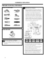
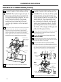
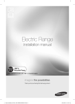
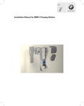
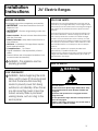
Installation
Instructions
24" Electric Ranges
BEFORE YOU BEGIN
FOR YOUR SAFETY:
Read these instructions completely and carefully.
All rough-in and spacing dimensions must be met for
safe use of your range. Electricity to the range can be
disconnected at the outlet without moving the range if
the outlet is in the preferred location (remove lower
drawer).
• IMPORTANT - Save these instructions for local
inspector's use.
• IMPORTANT - Observe all governing codes and
ordinances.
• Note to Installer - Be sure to leave these instructions
with the Consumer.
• Note to Consumer - Keep these instructions for future reference.
• Skill level - Installation of this appliance requires
basic mechanical skills.
• Completion time - 1 to 3 hours.
• Proper installation is the responsibility of the installer.
• Product failure due to improper installation is not
covered under the Warranty.
WARNING - This appliance must be
properly grounded.
To reduce the risk of burns or fire when reaching over
hot surface elements, cabinet storage space above
the cooktop should be avoided. If cabinet storage
space is to be provided above the cooktop, the risk
can be reduced by installing a range hood that sticks
out at least 5” beyond the front of the cabinets. Cabinets installed above a cooktop must be no deeper
than 13".
Be sure your appliance is properly installed and
grounded by a qualified technician.
Make sure the cabinets and wall coverings around the
range can withstand the temperatures (up to 200 °F)
generated by the range.
ANTI-TIP DEVICE
WARNING
FOR YOUR SAFETY:
WARNING - Before beginning the installation, switch power off at service panel
and lock the service disconnecting
means to prevent power from being
switched on accidentally. When the service disconnecting means cannot be
locked, securely fasten a prominent
warning device, such as a tag, to the
service panel.
Tip-Over Hazard
A child or adult can tip the range and be killed. Verify
the anti-tip bracket has been properly installed and
engaged.
Ensure the anti-tip bracket is re-engaged when the
range is moved.
Do not operate the range without the anti-tip bracket in
place and engaged.
Failure to follow these instructions can result in death or
serious burns to children or adults.
31
Installation Instructions
PREPARE TO INSTALL THE RANGE
TOOLS YOU WILL NEED
Drill with 1/8” Bit
2 PREPARE THE OPENING
Safety Glasses
Adjustable Wrench
Tape Measure
Pliers
Pencil
1/4” Nut Driver
Level
Phillips Screwdriver
Flat-blade Screwdriver
• Allow 2" spacing from the range to adjacent vertical walls above the cooktop surface. Allow 30"
minimum clearance between the surface units
and the bottom of unprotected wood or metal
top cabinet, and 18" minimum between the
countertop and the adjacent cabinet bottom.
• To eliminate the risk of burns or fire when reaching over hot surface elements, cabinet storage
space above the cooktop should be avoided. If
cabinet storage space is to be provided above
cooktop, the risk can be reduced by installing a
range hood that protrudes at least 5” beyond the
front of the cabinets. Cabinets installed above a
cooktop may be no deeper than 13".
PARTS INCLUDED
Anti-Tip Bracket Kit
Model
1 REMOVE SHIPPING MATERIAL
Remove packaging materials. Failure to remove
packaging materials could result in damage to the
appliance.
REX242W
REX243B
A
B
C
(recommended)
D
47"
24 3/8"
2"
41"
Flooring under the range
Your range, like many other household items, is
heavy and can settle into soft floor coverings such
as cushioned vinyl or carpeting.
When moving the range on this type of flooring, it
should be installed on a 1/4" thick sheet of plywood (or similar material) as follows:
When the floor covering ends at the front of the
range, the area that the range will rest on should
be built up with plywood to the same level or
higher than the floor covering. This will allow the
range to be moved for cleaning or servicing.
32
Installation Instructions
ELECTRICAL CONNECTIONS
ELECTRICAL REQUIREMENTS
CAUTION: For personal safety, do not
use an extension cord with this appliance. Remove house fuse or open circuit breaker before beginning installation.
This appliance must be supplied with the proper voltage and frequency, and connected to an individual
properly grounded branch circuit, protected by a circuit breaker or fuse having an amperage as specified
on the rating plate. The rating plate is located under
the cooktop or in the front frame. (See below pictures).
We recommend you have the electrical wiring and
hookup of your range connected by a qualified electrician. After installation, have the electrician show you
where your main range disconnect is located.
Check with your local utilities for electrical codes which
apply in your area. Failure to wire your oven according
to governing codes could result in a hazardous condition. If there are no local codes, your range must be
wired and fused to meet the requirements of the Canadian Electrical Code, Part 1 Latest Edition.
33
Installation Instructions
ELECTRICAL CONNECTIONS
ELECTRICAL REQUIREMENTS
WARNING: For personal safety, do not
use an extension cord with this appliance. Remove house fuse or open circuit breaker before beginning installation.
This appliance must be supplied with the proper voltage and frequency, and connected to an individual
properly grounded branch circuit, protected by a circuit breaker or fuse having amperage as specified on
the rating plate. The rating plate is located above the
storage drawer on the oven frame.
We recommend you have the electrical wiring and
hookup of your range connected by a qualified electrician. After installation, have the electrician show you
where your main range disconnect is located.
Check with your local utilities for electrical codes which
apply in your area. Failure to wire your oven according
to governing codes could result in a hazardous condition. If there are no local codes, your range must be
wired and fused to meet the requirements of the National Electrical Code, ANSI/ NFPA No. 70- Latest Edition.
You can get a copy by writing:
National Fire Protection Association
Batterymarch Park
Quincy, MA 02269
Effective January 1, 1996, the National Electrical Code
requires that new construction (not existing) utilize a 4conductor connection to an electric range.
When installing an electric range in new construction,
follow Steps 3 and 5 for 4-wire connection.
You must use a 3-wire, single-phase A.C. 208Y/120 Volt
or 240/120 Volt, 60 hertz electrical system. If you connect to aluminum wiring, properly installed connectors
approved for use with aluminum wiring must be used.
If the electrical service provided does not meet the
above specifications, have a licensed electrician install
an approved outlet.
NOTE: Use of automatic, wireless, or wired external
switches that shut off power to the appliance, are not
recommended for this product.
34
Use only a 3-conductor or a 4-conductor UL-listed
range cord. These cords may be provided with ring terminals on wire and a strain relief device.
A range cord rated at 40 amps with 125/250 minimum
volt range is required. A 50 amp range cord is not recommended but if used, it should be marked for use
with nominal 13/8" diameter connection openings.
Care should be taken to center the cable and strain relief within the knockout hole to keep the edge from
damaging the cable.
• Because range terminals are not accessible after
range is in position, flexible service conduit or cord
must be used.
NOTE: If conduit is being used, go to Step 3D and then
to Step 6 or 7.
• On some models, a filter capacitor may be connected between the black and white leads on the
junction block.
ALL NEW BRANCH CIRCUIT INSTALLATIONS, MOBILE HOMES, RECREATIONAL VEHICLES AND INSTALLATIONS WHERE LOCAL CODES DO
NOT ALLOW GROUNDING
THROUGH NEUTRAL, REQUIRE A 4CONDUCTOR CORD OR CONDUIT.
Installation Instructions
ELECTRICAL CONNECTIONS (CONT.)
3 POWER CORD AND STRAIN RELIEF
INSTALLATION
A
C
Remove the wire cover (on the back of the range) by
removing two (2) screws using a Phillips screw driver.
Do not discard these screws.
For power cord installations only (see the next step if
using conduit), assemble the strain relief in the hole.
Insert the power cord through the strain relief and
tighten. Allow enough slack to easily attach the cord
terminals to the terminal block. If tabs are present at
the end of the winged strain relief, they can be removed for better fit.
NOTE: Do not install the power cord without a strain relief. The strain relief bracket should be installed before
reinstalling the rear range wiring cover.
Terminal
block
2 screws
to remove
wire cover
Strain relief
Power cord
Back of Range
B
Skip to Step 4 or 5.
Wire cover
Remove the knockout ring (1 3/8") located on
bracket directly below the terminal block. To remove
the knockout, use a pair of pliers to bend the knockout ring away from the bracket and twist until ring is
removed.
Terminal block
(appearance
may vary)
Bracket
D
For conduit installations only, purchase a squeeze
connector matching the diameter of your conduit
and assemble it in the hole. Insert the conduit through
the squeeze connector and tighten. Allow enough
slack to easily attach the wires to the terminal block.
NOTE: Do not install the conduit without a squeeze
connector. The squeeze connector should be installed before reinstalling the rear range wiring cover.
Terminal
block
Squeeze
connector
Knockout ring
in bracket
Knockout ring
removed
Conduit
Bracket
Skip to Step 6 or 7.
35
Installation Instructions
ELECTRICAL CONNECTIONS (CONT.)
4 3-WIRE POWER CORD INSTALLATION
5 4-WIRE POWER CORD INSTALLATION
WARNING: The neutral or ground wire of
the power cord must be connected to
the neutral terminal located in the center of the terminal block. The power
leads must be connected to the left
and the right terminals of the terminal
block.
A
Remove the 3 lower terminal screws from the terminal block. Insert the 3 power cord terminal rings
into each one of the terminals of the terminal
block. Be certain that the center wire (white/neutral) is connected to the center of the terminal
block. Tighten nuts securely into the terminal block.
DO NOT remove the ground strap connection.
Terminal block
(appearance
may vary)
Ground
plate
Power
cord
WARNING: The neutral wire of the supply
circuit must be connected to the neutral terminal located in the center of the
terminal block. The power leads must
be connected to the left and the right
terminals of the terminal block. The 4th
grounding lead must be connected to
the frame of the range with the ground
plate and the ground screw.
A
Remove the 3 lower terminal nuts from the terminal
block. Remove the ground screw and ground
plate and retain them.
B
Cut and discard the ground strap. DO NOT DISCARD ANY SCREWS.
C
Insert the one ground screw into the power cord
ground wire terminal ring, through the ground plate
and into the frame of the range.
D
Insert the 3 terminal screws (removed earlier)
through each power cord terminal ring and into
the lower terminals of the terminal block. Be certain
that the center wire (white/neutral) is connected to
the center lower position of the terminal block.
Tighten screws securely into the terminal block.
Neutral
terminal
Ground strap
Ground
strap
Before
or
Terminal
block
Ground strap
After
B
Skip to Step 8 and proceed with the installation.
Terminal
block
Neutral
terminal
Neutral terminal
Ground
plate
(grounding
to range)
Ground
screw
E
36
Skip to Step 8 and proceed with the installation.
Installation Instructions
ELECTRICAL CONNECTIONS (CONT.)
6 3-WIRE CONDUIT INSTALLATION
7 4-WIRE CONDUIT INSTALLATION
A
A
Loosen the 3 lower terminal screws from the terminal block. Insert the center bare wire (white/ neutral) tip through the bottom center terminal block
opening. On certain models, the wire will need to
be inserted through the ground strap opening and
then into the bottom center block opening. Insert
the two side bare wire tips into the lower left and
the lower right terminal block openings. Tighten the
screws until the wire is firmly secure (approximately
20 inch-lbs.).
NOTE: ALUMINUM WIRING:
Loosen the three lower terminal screws from the
terminal block. Remove the ground screw and
ground plate and retain them.
Cut and discard the ground strap.
DO NOT DISCARD ANY SCREWS.
B
Aluminum building wire may be used but it must be
rated for the correct amperage and voltage to
make connection. Connect wires according to this
Step 6 or Step 7 depending on number of wires.
Insert the ground bare wire tip between the range
frame and the ground plate (removed earlier) and
secure it in place with the ground screw (removed
earlier). Insert the bare wire (white/neutral) tip
through the bottom center of the terminal block
opening. Insert the two side bare wire tips into the
lower left and the lower right terminal block openings. Tighten the screws until the wire is firmly secure
(approximately 20 inch-lbs.).
Wire used, location and enclosure of splices, etc.,
must conform to good wiring practices and local
codes.
Terminal
block
Ground strap
Before
Wire tips
Terminal
block
Ground strap
Bracket
or
Neutral
terminal
Conduit
After
Wire used, location and enclosure of splices, etc.,
must conform to good wiring practices and local
codes.
B
Neutral terminal
Terminal
block
Skip to Step 8 and proceed with the installation.
Ground
plate
(grounding
to range)
Ground
screw
C
Proceed to Step 8.
8 REPLACE THE WIRE COVER
Replace the wire cover on the range back by sliding its two lower retaining tabs into the slots and replacing the screw removed earlier. Make sure that
no wires are pinched between the cover and the
range back.
37
Installation Instructions
INSTALL THE RANGE
9 ANTI-TIP DEVICE INSTALLATION
WARNING
10 REMOVE STORAGE DRAWER
A
Pull the drawer out all the way.
Lift the front of the drawer until the stops clear the
guide.
Remove the drawer.
B
Lift the front of the drawer until the stops clear the
guide.
C
Remove the drawer.
Tip-Over Hazard
A child or adult can tip the range and be killed. Verify
the anti-tip bracket has been properly installed and
engaged.
Ensure the anti-tip bracket is re-engaged when the
range is moved.
Do not operate the range without the anti-tip bracket in
place and engaged.
Failure to follow these instructions can result in death or
serious burns to children or adults.
To reduce the risk of tipping the range, the range must
be secured by a properly installed anti-tip bracket. See
installation instructions shipped with the bracket for
complete details before attempting to install.
To check if the bracket is installed and engaged properly, look underneath the range to see that the anti-tip
arm attached to the side panel is engaged in the
bracket. On some models, the storage drawer or kick
panel can be removed for easier inspection. If visual inspection is not possible, slide the range forward, confirm the anti-tip bracket is securely attached to the floor
or wall, and slide the range back so the anti-tip arm
slides just under the anti-tip bracket. If the range is
pulled from the wall for any reason, always repeat this
procedure to verify the range is properly secured by
the anti-tip bracket.
11 LEVEL THE RANGE
A
Install the oven racks in the oven and position the
range where it is to be installed.
B
Check for levelness by placing a spirit level or a
cup, partially filled with water, on one of the oven
racks. If using a spirit level, take two readings - with
the level placed diagonally first in one direction
and then the other.
C
The front leveling legs can be adjusted from the
bottom and the rear legs can be adjusted from the
top or the bottom.
Lower
range
Leg
leveler
Raise
range
D
38
Use an open-end or adjustable wrench to adjust
the leveling legs until the range is level.
Installation Instructions
11 FINAL INSTALLATION CHECKLIST
• Check to make sure the circuit breaker is closed
(RESET) or the circuit fuses are replaced.
• Be sure power is in service to the building.
• Note (on some models): If the clock flashes "bad"
and then "LinE" with a loud tone, the neutral connection to the range is miswired. Check the terminal block connections and/or house wiring to
correct.
• Check to be sure that all packing materials and
tape have been removed. This will include tape
on metal panel under control knobs (if applicable), adhesive tape, wire ties, cardboard and
protective plastic. Failure to remove these materials could result in damage to the appliance once
the appliance has been turned on and surfaces
have heated.
• Check to make sure that the rear leveling leg is
fully inserted into the Anti-Tip bracket and that the
bracket is securely installed.
12 OPERATION CHECKLIST
• Turn on one of the surface units to observe that
the element glows within 60 seconds. Turn the unit
off when glow is detected. If the glow is not detected within the time limit, recheck the range
wiring connections. If change is required, retest
again. If no change is required, have building wiring checked for proper connections and voltage.
• Check to make sure the Clock (on models so
equipped) display is energized. If a series of horizontal red lines appears in the display, disconnect
power immediately. Recheck the range wiring
connections. IF change is made to connections,
retest again. If no change is required, have building wiring checked for proper connections and
voltage. It is recommended that the clock be
changed if the red lines appear.
• Be sure all range controls are in the OFF position
before leaving the range.
39