1
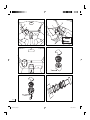
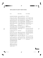
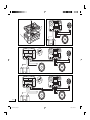
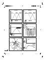
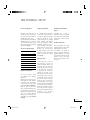
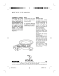
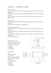
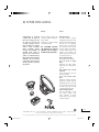
K2 Power User Manual
Congratulations on purchasing
a product from the range, K2
Power. We are happy you share
our passion, for the "the Spirit
of Sound". Designed using the
latest technology, these speakers
continue
Focals
perfectionist
beliefs,
developing
products
with high power handling, and
unrivalled sound quality. To
obtain the best results from this
product, we recommend that you
follow carefully all the information
contained in this user’s manual.
If not followed correctly any fault
observed, may not be covered by
the guarantee.
Warning
Features
Continued listening at high volume
levels above 110dB, are damage your
hearing durably
Listening above 130dB can damage
your hearing permently.
Membrane K2 Power:
New CMKV sandwich composite,
including (Kevlar, foam, and structural
glass fibre). Three individual materials,
each with their own advantages,
allow the cone to be extremely rigid,
with continued low mass value, and
increased damping characteristics,
even when played loud. This ensures
improved power handling, with
detailed sound quality, low distortion
even at high volume levels.
Chassis made from Zamak:
Inherently rigid and non magnetic.
Voice coil wound on Kapton
former:
Light-weight and highly durable
material ensures no deformation of
voice coil.
Butyl moulded rubber surround
suspension:
Long life characteristics, even in the
most extreme climates.
TN 52 with inverted tweeter
dome:
Inverted dome formed from titanium
treated Tioxid 5 material. Producing
detailed high frequencies, acoustically
rich and dynamic. Controlled with
twin radius wave guides, for totally
controlled staging and directivity.
Crossover of high precision:
Precise level adjustment of tweeter
and
medium
available.
High
quality
audiophile
components
used throughout. Large wire gauge
connections included.
The Focal-JMlab guarantee
only applies if the enclosed
guarantee card is returned to
us within 10 days of purchase.
09 English
®
Focal- JMlab - BP 374 - 108, rue de l'Avenir - 42353 La Talaudière cedex - France - www.focal-fr.com
Tel. 00 33 4 77 43 57 00 - Fax 00 33 4 77 43 57 04
Due to constant technological advances, Focal reserves its right to modify specifications without notice. Images may not conform exactly to specific product. ©Focal-JMlab
notice kit k2 power gb 1
7/07/05, 11:37:54
English 10
A
B
C
D
E
F
notice kit k2 power gb 2
7/07/05, 11:37:55
Installation and positioning
Tweeter
Woofer-midrange
Tweeter installation
The TN52 tweeter has been designed
for flush mount or surface mount
positioning, using the two fixing kits
provided. The choice of install position
is extremely important to deliver
the best performance and maintain
integration into the system. This is a
major factor for high frequency SPL,
and the the stability of the acoustics,
stereophonic imaging, and overall
staging. Please check the drawing to
understand this further.
The standard recommendation for
ideal stereo imaging, is to ensure the
tweeters "left" and "right", are installed
in the same positions. Also they are
approximately at equal distance to the
driver (vice-versa for the passenger).
The various positions advised should
be verified and comparatives made,
for ideal positioning.
The tweeter should always be
positioned ahead of the normal
listening position. The main preferences are the outer positions of the
dash board (fig. A, 1), close to the
windshield (fig. A, 2). Normally easy
for installation. The location close
to the door mirror (fig. A, 3) is also
regarded as a good position, and
normally only requires a small amount
of install work. Lastly a position high in
the doors (fig. A, 4) is also acceptable
even if it is not considered the best for
optimised staging. It is imperative
to verify before any installation is
attempted, that enough space is
available (especially for flush-mount
applications). Also that there will be
no interference with security devices
air-bags, door latches etc.
K2 Power woofer-midranges, positioned ideally high in the doors
(fig. B, 1), produce optimal midrange
frequencies, thus integrating better into
the rest of the system. The 100 KP Slim
thanks to its reduced depth feature
allows easy installation into the outer
positions of the dashboard (fig. B,
2). If the woofer-mids are positioned
low in the doors (fig. B, 3), the loss
of midrange can be compensated by
adjusting the crossover (see section
"adjustment" page 15).
The woofer-mids from the K2 Power
range can also be placed low in
the "kick-panels" (fig. B, 4) of the
vehicle. This is to further optimise the
stereophonic imaging.
Surface-mount
Centre Channel
Ideally suited for an audio video
installation using DVD multi channel
inputs (Dolby Digital, DTS etc), the
ultra compact midrange 100 KP
Slim, has obvious advantages. With
minimum depth dimension 39mm
(1.58"), due to its efficient neodymium
motor, the 100 KP is ideal for centre
channel applications, in normally
difficult locations such as the dash
board (fig. C).
The flush-mounting fixing kit supplied
offers two possibilities for installing
the TN52 in an angle of 10°/30°.
This allows more flexibility for the
installation (fig. D).
Fix the assembly using the two screws
provided. Thread the cable from the
tweeter, through the back.
Then decide the defined angle and
lock in place on the support.
Flush-mount
(highly recommended)
Cut a perfectly round hole of 45mm
(1,77“) Push in the support and
ensure it remains flat on the surface.
Ensure it is locked in place with the
screws supplied. Thread the cable
from the tweeter, through the back.
Then decide the defined angle and
lock in place the tweeter on the
support (fig. E).
Attention : It is not necessary to twist
lock the TN52 in place using a locking
tool (as for TN47).To do so, carefully
push and turn on the outer radius
wave guides, turning the tweeter until
it is locked in place.
11 English
notice kit k2 power gb 3
7/07/05, 11:37:55
G
H
I
English 12
J
notice kit k2 power gb 4
7/07/05, 11:37:55
Installation and positioning
notice kit k2 power gb 5
Woofer and woofer-midrange
recommendations
Woofer and woofer-midrange
installation, simple steps (with grille)
2-Way kits connecting up, simple
steps
K2 Power woofers and woofermidranges have been designed for
a multitude of vehicles installations.
It is worth understanding the basic
requirements for installing such
products. These woofers and woofermidranges are capable of delivering
enormous amounts of energy, during
their positive/negative movement.
Therefore it is imperative that they
be fixed rigid to the desired location.
The fixing location should also be
strengthened
where
necessary.
Panels should be strengthened to
eliminate any unwanted vibrations.
Such vibrations will drastically reduce
the overall performance. These drive
units should be fixed and sealed to
the baffle or location panel. The use
of the foam gasket is advisable for
correct air sealing.
For added performance, and to better
reduce such unwanted vibrations
and other acoustical losses, we
recommend the use of "plain chant".
Easily positioned behind the woofer,
on the metal-work of the vehicle, Plain
Chant soaks-up vibrations as well as
acoustic reflections.
Always ensure before that enough
space is available for the magnet
assembly, that it doesn’t interfere with
safety mechanisms or general working
parts.
In the case of not using the grilles
supplied, it is important to ensure the
speakers will fit correctly. Ensuring
there is enough depth behind the
speaker has already been explained,
but enough thought must also be
given for the forward movement of the
cone and surround assembly.
Either cut the required hole or use the
correct hole of choice. Note correct
diameter (fig. F). Where necessary,
carefully push in the four fixing clips to
accept the fixing screws later.
Carefully place the fixing ring,
ensuring it lines-up with the holes or
fixing clip positions.
Fix the foam gasket to the back of the
drive unit chassis. Add a small amount
of glue where necessary, so it remains
in the correct position (line-up holes).
Lower the drive unit above the fixing
ring, so it remains in the correct
position (line-up holes).
Don’t forget to connect up the cable
to the connectors.
Now lower the drive unit and screw in
place, with the 4 screws provided.
Now add the grille and push in place.
Ensure the logo is straight.
Connect the output from the amplifier
into the input of the crossover "IN".
Connect the woofer to the output of
the crossover "W".
Connect the tweeter to the output of
the crossover "T" (fig. H).
Finally always ensure the tweeter
and woofer are connected in phase
correctly, thus polarities are respected
"+" to "+", and "-" to "-". If not done
correctly a "hole" or "peak", may
result, due to a shift in phase. This
will dramatically impair the overall
performance.
Crossover installation, simple steps
First before any work is started it is
necessary to remove the clear plastic
lid (fig. G).
Doing so enables access for
adjustment, and fixing the unit in
place.
Remove, by pushing gently on the two
shortest sides of the clear plastic lid.
Then pull off.
Never use a screwdriver to prise off the
lid, otherwise damage will probably
occur, not covered by the warranty.
Once removed, fix in place with the
4 screws supplied. Ensure the length
of screw is suitable for the desired
location. Always ensure the crossover
is installed in a dry and vented area,
without risk of humidity.
3-Way kits connecting up
(165 K3P)
The 165 K3P uses two crossovers,
connected together. The exclusive
165 KBP low frequency cross-over,
has two configurations for filtering.
These being mode:
"High Pass" (fig. I, and K), for a true
3 way set-up, with separate bass mid
and high frequencies.
"Full" (fig. J, and L), for a 2+1 way
set-up, with 2x165mm in parallel, for
more dynamic fast bass.
Important (165K3P)
Depending on the preferred set-up,
the selector found in the 165KBP,
must be switched accordingly.
The mode "Full" (F),requires inverting
the connections, for input (fig. I, and J).
Doing this will ensure the overall
phase will remain correct. Because
this mode has a low impedance value
of approximately 2 ohms, verify if the
low loading is compatible for your
amplifier.
13 English
7/07/05, 11:37:55
English 14
K
L
M
N
O
P
notice kit k2 power gb 6
7/07/05, 11:37:56
Fine tunning / set-up
Tweeter level adjustment
Staging level adjustment
Information of other K2 Power
products
Adjustments to the tweeter level, can
be made at precise increments, using
the selector buttons found inside on
the PCB board of the crossover.
These are indicated as -1dB, -2dB and
-4dB. By pushing in one or several of
these selector buttons, allows various
reductions of level, from -7dB total by
1dB increments (fig. M).
The radiused-profiled wave-guides
on the exterior of the TN52 tweeter,
can control the directivity of the high
frequencies. Thereby, the acoustic
energy available can be controlled
by the orientation of this radiused
profile. This characteristic essentially
adds further benefit to the user, to
control the staging of the system, or
defining better the virtual acoustic
imaging of the sound produced.
By simply turning the tweeter and
changing the position of the radiused
profiles, will modify this staging
aspect (fig. N).
Focal-JMlab offer a range of
subwoofers from the 13 KS (130mm
/5") to the impressive 46 KX4 (460mm
/18") Consult your dealer for futher
information.
Tweeter level adjustment table
-1dB
-2dB
-4dB
Total
0
0
0
0dB
1
0
0
-1dB
0
1
0
-2dB
1
1
0
-3dB
0
0
1
-4dB
1
0
1
-5dB
0
1
1
-6dB
1
1
1
-7dB
Midrange level adjustment
The crossover contains a specific
level adjustment for the midrange
frequencies.
Fitting the drive units high up in the
vehicle requires the mode " Mid flat "
to be used. Doing so will ensure the
overall response curve of the system
remains linear (fig. O, A and fig. P).
Fitting the drive units low in the
vehicle, especially in the bottom of the
door for example, requires the mode
"Mid High" to be used. Doing so will
ensure such normally directional
frequencies are not "masked" or lost
in the textiles of the vehicle (fig. O, B
and fig. P).
Running-in period
Conditions of guarantee
All Focal loudspeakers are covered
by guarantee drawn up by the official
Focal distributor in your country.
Your distributor can provide all
details concerning the conditions of
guarantee. Guarantee cover extends
at least to that granted by the legal
guarantee in force in the country
where the original purchase invoice
was issued.
K2 Power drive units use the very
latest components. To ensure such
complex mechanical elements work
in harmony with each other, they
must be allowed to function correctly
in this environment. Such changes
in temperature and humidity are
regarded as very hostile. For K2
Power speakers to benefit, a runningin period must be used to ensure they
are prepared for this. We recommend
that once the system is ready for
listening the drive units should be
run-in with medium volume setting,
with music that has the full bandwidth
of frequencies (sub-bass through to
treble). This running-in period should
be used for a few weeks, to gain the
full potential. After which the excellent
performance of your K2 Power
products can be fully appreciated.
15 English
notice kit k2 power gb 7
7/07/05, 11:37:56
specifications
Kit
100 KP
130 KP
165 KP
165 K2P
165 K3P
Maximum power
100W
140W
160W
200W
400W
Nominal power
50W
70W
80W
100W
200W
Sensitivity
90dB
90dB
91dB
92.5dB
95.5dB
120 to 22 000Hz
70 to 22 000Hz
60 to 22 000Hz
70 to 22 000Hz
60 to 22 000Hz
3.5kHz to 12dB/oct
3.5kHz to 12dB/oct
3.8kHz to 18dB/oct
3.8kHz to 18dB/oct
200Hz/3.8 kHz to 18dB/oct
4 ohms
4 ohms
4 ohms
4 ohms
4 ohms (H)/2 ohms (F)
Frequency response
Crossover
Nominal impedance
TN 52
TN 52
TN 52
TN 52
TN 52
Inverted Tioxid 5
Inverted Tioxid 5
Inverted Tioxid 5
Inverted Tioxid 5
Inverted Tioxid 5
Neodymium
Neodymium
Neodymium
Neodymium
Neodymium
1955Hz
1955Hz
1955Hz
1955Hz
1955Hz
DC resistance (Re)
5.8 ohms
5.8 ohms
5.8 ohms
5.8 ohms
5.8 ohms
Woofer/midrange
4 K Slim
5 KP
6 KP
6 K2P
4” K2 sandwich
5” K2 sandwich
6” K2 sandwich
6” K2 sandwich
6” K2 sandwich
6” K2 sandwich
100mm
130mm
165mm
165mm
165mm (medium)
165mm (woofer)
Voice coil
1“ - 25mm
1“ - 25mm
1“ - 25mm
1.6” - 40mm
1.6” - 40mm
1.6” - 40mm
Magnet
Neodymium
3.4” - 85mm
3.4” - 85mm
4” - 100mm
4” - 100mm
4” - 100mm
Butyl
Butyl
Butyl
Butyl
Butyl
Butyl
140Hz
88.6Hz
73Hz
69Hz
69Hz
68Hz
Tweeter
Cone
Magnet
Resonant frequency (Fs)
Cone
Surround
Resonant frequency (Fs)
notice kit k2 power gb 8
6 K3P
3.2 ohms
3.2 ohms
3.0 ohms
2.9 ohms
2.9 ohms
2.9 ohms
Vas
0.039Ft - 1.13 litres
0.17Ft3 - 4.93 litres
0.27Ft3 - 7.71 litres
0.3Ft3 - 8.64 litres
0.3Ft3 - 8.64 litres
0.27Ft3 - 7.7 litres
Qes
0.96
O.74
0.81
0.7
0.7
0.66
Qms
9.55
8.06
9.01
9.13
9.13
9.46
Qts
0.87
0.68
0.74
0.65
0.65
0.62
Sd
8.6in2 - 55.4cm2
13.42in2 - 86.6cm2
20.57in2 - 132.7cm2
20.57in2 - 132.7cm2
20.57in2 - 132.7cm2
20.57in2 - 132.7cm2
Bl
3.8N/A
5.09N/A
5.09N/A
5.26N/A
5.26N/A
5.8N/A
Xmax
0.1” - 2.5mm
0.1” - 2.5mm
0.2” - 5mm
0.18” - 4.5mm
0.18” - 4.5mm
0.18” - 4.5mm
Cut -out diameter
3.67" - 93mm
4.53" - 115mm
5.60" - 142mm
5.60" - 142mm
5.60" - 142mm
5.60" - 142mm
Mounting depth
1.54" - 39mm
2.41" - 61mm
2.80" - 71mm
3.03" - 77mm
3.03" - 77mm
3.03" - 77mm
DC resistance (Re)
English 16
6 K2P
7/07/05, 11:37:56