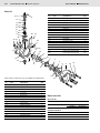
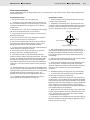
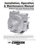
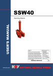
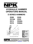
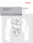
1
Industrial
Hydraulics
Electric Drives
and Controls
Linear Motion and
Assembly Technologies
Pneumatics
Service Manual for
Hydraulic Vane Pumps
Flange Mounted
Service
Automation
Mobile
Hydraulics
SM PSCF/07.03
1/06
PVC Series
PVC PSCF 09GRM-01 Flanged Series Pump
PVC PSCF 12ERM-01 Flanged Series Pump
Contents
Installation ................................................................................................. 1
Start-up procedures ................................................................................ 2
Operating instructions ............................................................................ 3
Parts list ..................................................................................................... 4
Pump repair procedures ........................................................................ 5
Installation
CAUTION - Before performing any service
operation on any pump, be sure that all pressure has been
relieved from BOTH SIDES of the system.
PVC
ORDERING CODE
PVC PSCF 12 ERM-01
CAUTION - Before performing any service
operation on any pump, disconnect or lock
off power supply.
CAUTION - Before starting pump, be sure
that any resulting machine function will not
endanger persons or equipment.
Product identification
Each pump has an Ordering Code stamped on its nameplate.
See Figure 1 for the location of the Ordering Code.
Figure 1
2/06
Bosch Rexroth Corp.
Industrial Hydraulics
Service Manual
SM PSCF/07.03
Installation (continued)
Start-up procedures
Pump drive and mounting
The following instructions apply for initial startup of the hydraulic
pump. After an extended shutdown period, start with item 5.
When mounting the pump and motor, care must be taken to align
the pump and motor shafts within .003 T.I.R. direct inline through
a jaw type/flexible web coupling. This is recommended for all
Rexroth pumps. Tire-type flexing elements and chain-type drives
are not recommended. With belt drives, please consult factory.
To avoid axial and radical end loading of the pump shaft, do not
couple the pump and motor shafts rigidly. Allow freedom at the
coupling for the two shafts to ride independently.
To prevent end loading, the space between the pump and motor
shaft ends should be 1/2 inch for PVC pumps, or as the coupling
manufacturer specifies.
Piping and Reservoir
The pump should be mounted with a minimum number of elbows
or fittings. The pump suction should be at least 1 inch tube/pipe
for PVC pumps.
For any system and combination of piping except High Water
Based Fluids (HWBF), the vacuum at the pump inlet must not
exceed seven inches of Mercury, (5 inch Hg. for fire resistant
fluids). HWBF Pumps are to have a positive inlet head in the
range of 0.5-inch Hg. to 20 inch Hg.
Piping should be done with pickled pipe or seamless tubing free
of dirt and scale. Do not use galvanized or other pipe that tends
to flake off.
A 100-mesh screen (60 mesh for fire resistant and HWBF)
should be used on the pump suction line. The screen should be
located approximately two inches from the bottom of the tank. All
lines returning oil to the tank should discharge at least two inches
below the minimum oil level and should be separated from the
pump suction area by means of a baffle. These lines should also
include a 10-micron return line filter, with the exception of the
case drain line.
The pump case drain should be connected directly to the tank.
Pressure in excess of 10 psi in the case drain line can result in
shaft seal leakage. It is recommended that the case drain be
returned to the tank by a separate 3/8-inch line.
CAUTION - Never start a new pump installation against
a blocked system.
1. Check the name plate for model number and rpm. The arrow
on the pump casting indicates direction of rotation.
2. Pump suction line should extend below the lowest point of oil
level but not less than two inches above reservoir bottom.
3. The pump and motor shafts must be aligned within .003
inches. (See Pump Drive and Mounting directions above for
restrictions).
4. Connect the case drain directly to tank (or to a heat exchanger if the pump will be deadheading for long periods of time
during operation), using a full-size line corresponding to the case
drain in the pump or manifold. If connected to a heat exchanger,
the case drain line should be protected with a 10 psi. maximum
relief valve in parallel with the heat exchanger. No other return
lines should be connected in common with the case drain return.
5. Rotate pump and motor by hand to insure free rotation.
6. Set the machine controls to open the circuit and allow free
flow from the pump back to tank or connect the pump outlet line
directly to tank. Jog the motor on and off several times (on, two
seconds, off three seconds) until the pump is primed. Check
pump for proper direction of rotation during the jogging.
7. After the pump has been primed, run it for several minutes at
lower than normal pressures with an open or intermittently open
system which permits oil flow. This will purge entrapped air from
the pump and system.
8. Neither volume adjustment nor pressure adjustment should
be adjusted until the pump has been primed and running, and air
is purged.
9. After air has been purged from the system, the system can
be closed and the pump adjusted to the required operating
pressure.
10. If necessary, the volume adjustment can be adjusted to the
required operating pressure.
11. When replacing pumps, the suction screen in the reservoir
must be removed and thoroughly cleaned. Also, the suction line
from the reservoir to the pump should be flushed inside and out
to remove any contaminants. Pieces of metal from a damaged
pump can back up into this line. If they are not removed, they will
be drawn into the new pump and destroy it. Start unit by using
proper pump start-up procedure items 1 through 10.
CAUTION - If both pressure and volume modifications
are supplied on the pump, the pressure should be
adjusted before the volume. Volume should be
adjusted at minimum pump pressure or at deadhead. Stop
adjustment at the volume screw when pressure begins to drop.
SM PSCF/07.03
Service Manual
Industrial Hydraulics
Bosch Rexroth Corp.
3/06
Operatiang procedures
Pressure and volume adjustments
Pressure and Volume Adjustment Sensitivity
Pressure control
All pumps are adjusted to reduced pressure before shipment and
must be readjusted to the required system pressure after installation and start-up.
The pressure adjusting screw is located at the end face of the
compensator chamber. See parts page item number 30. The
adjusting screw has a right hand thread; clockwise adjustment
increases pressure; counterclockwise reduces pressure. A
pressure gauge located at the pump must be used when making
adjustment to insure the pressure settings do not exceed limits
specified for the particular pump of maximum system pressure.
Make all pressure settings with pump operating against a closed
circuit, that is with the output of the pump blocked, and then
check pressure throughout the pump flow range.
Volume control
Adjust volume at minimum pump pressure or at pump deadhead.
The volume adjusting screw is directly opposite the pressure
adjusting screw, see parts page item number 55. The adjusting
screw has a right hand thread, turning the screw clockwise
decreases the maximum volume, turning the screw counterclockwise increases the maximum volume. Pumps are set at a
maximum rated volume at the factory unless otherwise specified.
Stop adjustment of the volume screw when pressure begins to
drop. See Sales Catalog for complete pump performance
specifications.
Adjustment procedures
To adjust the maximum output volume use the following steps:
1. Set the pump at minimum pressure.
2. Hand tighten the volume screw until it touches cam ring.
NOTE: The pump should be at full flow for this step.
3. See Pressure and Volume Adjustment Sensitivity chart below.
4. Deadhead the pump, turn the volume screw the proper
number of turns to obtain the flow desired.
5. Return pump to flow condition and check flow rate. If output
flow is incorrect, switch pump to deadhead and readjust per
above.
CAUTION - Turning the maximum volume control in
too far can force the cam ring over-center and destroy
the pump.
Pump Size
Pressure Code
Pressure
Adjustment
Pressure change/turn
Maximum torque
Flow change/turn
Volume
Adjustment
Approx. min. flow adj.
Maximum torque
PVC PSCF
09
PVC PSCF
12
G = 1500 psi E = 1000 psi
psi (bar)
260 (17.9)
235 (16.2)
ft-lbs (kg-M)
6.8 (0.83)
5.0 (0.89)
gpm (lpm)
gpm (lpm)
ft-lbs (kg-M)
4.6 (17.4)
1.25 (4.7)
2.5 (0.34)
1.0 (0.14)
4/06
Bosch Rexroth Corp.
Industrial Hydraulics
Service Manual
SM PSCF/07.03
Parts list*
30
ITEM
NO.
31
8
10
42
43
DESCRIPTION
NO.
REQ.
21
Bushing Bearing
2
22
Key
1
23
Spring Pin
3
CODE
24
Viton
Lip Seal
1
30
Viton
Pressure Adj. Screw Ass’y.
1
31
41
9
11
40
66
67
68
24 67
99
19
80
5
1
Straight Thread Plug
1
Spring Retainer
42
Shim (.005)
A.R.
43
Shim (.0149)
A.R.
66
Name Plate
1
67
Self-Tapping Screw
6
68
Escutcheon (Rotation Arrow)
1
80
Dowel Pin
2
92
SAE O-Ring Plug
1
1
Thrust Screw Plug Kit
Not
Shown
22
1
Spring Pin
41
99
13
21
Viton
1
Grease (Union 76 UNOBA EP2)
Grease (LED Plate #250) (#24)
A.R.
A.R.
7
6
55
23
4
15
17
2
92
18
3
23
*Parts shown for reference only, not available for individual sale.
ITEM
NO.
CODE
DESCRIPTION
21
NO.
REQ.
1
Pump Body
1
2
Cover
1
3
Rotorshaft
1
4
Port Plate
1
5
Thrust Plate
1
6
Pressure Ring
1
7
Vane Kit (Set of 13)
1
8
Spring Seat
1
9
Governor Spring
1
10
Follower Spring
1
11
Ring Shoe Assembly
1
13
Teflon Seal Ring
1
Repair parts kits
Viton seal kit
Includes items:
13, 15, 17, 24, 28, 30, 37, 55 & 99
15
Viton
O-Ring
1
16
Viton
O-Ring
1
17
Viton
O-Ring
1
Includes items:
3, 4, 5, 6, 7, 21 & Seal kit
18
Soc. Hd. Cap Screw
4
19
Thrust Screw
1
Model
Kit No.
09GRM-01
R978715448
12ERM-01
R978715448
Complete rebuild kit
Model
Kit No.
09GRM-01
R978715451
12ERM-01
R978715452
SM PSCF/07.03
Service Manual
Industrial Hydraulics
Bosch Rexroth Corp.
5/06
Pump repair procedures
NOTE: Disassembling pump to change components, or for any other reason, may void the warranty. Refer to Policy Statement and
Discounts Summaries.
Disassembly procedure
Reassembly procedure
1. Remove the key (22) in the rotor shaft keyway.
1. Clean and inspect parts to determine which parts are worn
enough to require replacement.
2. A small amount of oil may remain in the pump. Remove the
four cover bolts and slide the cover back far enough on the shaft
to break the seal between the housing and cover to allow the
pump to drain.
3. Remove the cover. Take care to avoid damage to the bearing
with the end of the shaft when the cover is removed.
2. Assemble the new bearings (21) in the housing and cover.
The bearing OD's should be lubricated before they are pressed in
the bores. Care must be taken to orient the "split" and the "oil
groove" in the bearing as shown in the illustration below.
Spring Housing
CL
4. The port plate (4) may come out with the cover. Do not let it
drop off the locating pins.
5. Remove the vanes (7) with a long nosed pliers or tweezers,
there is one vane in each slot, 13 vanes total.
6. Remove the rotorshaft (3) from the pump. Be sure that the
key (22) has been removed from the keyway so that it will not
damage the shaft seals when the rotorshaft is removed.
7. Turn the pressure adjustment screw (30) counterclockwise to
release the tension on the governor spring.
8. Remove the pressure ring (6), spring shoe (11), governor
spring (9), retainer (41) and follower spring (10).
9. If the shaft seals (24) are to be removed they should be
pushed out from the inside of the housing at this time. Care must
be taken not to damage the journal bearing in the housing while
the shaft seals are being removed. It is recommended that the
shaft seals be replaced whenever the pump is disassembled for
maintenance. The seals cannot be reused once they have been
removed.
10. The journal bearings (21) in the pumps are assembled with a
press fit. If they are to be removed at this time, the bearing in the
housing should be pressed out from the front. The cover bearing
should be pulled out using an expanding type puller. The
bearings should not be reused once they have been removed.
11. It is unlikely that further disassembly will be necessary in
order to perform routine maintenance on the pump.
CL Thrust
Screw
Oil Groove Positions
Item #21
Bushing Bearing Orientation
3. After the bearings are in place, check to see that the rotor
shaft will fit into the bearings and provide a smooth turning fit. If
the shaft turns hard, the bearings should be removed and the
bore checked closely for nicks or burrs before pressing in the
new bearings.
4. Check all of the replacement parts for nicks or burrs and then
lubricate them with clean oil before reassembly.
5. Worn port and thrust plates should not be reground to clean
up the wear surface. If the plates are ground, the assembly
clearance will become excessive and the seal rings in the thrust
plate may rupture. Replace worn port and thrust plates if
necessary.
6. Assemble the springs and spring shoe, ring and rotorshaft.
7. To assure proper vane assembly, place the vanes with the
beveled edge out against the pressure ring.
8. Assemble the square seal rings into the cavity in the back of
the thrust plate. The soft rubber seal rings should be assembled
first and the hard seat rings should be assembled on top of them.
Stretch the larger soft seal ring slightly so it clings to the ID at the
cavity. Apply clean oil or STP to the back of the thrust plate
before it is placed in the locating pins in the body to help hold the
parts together while they are assembled.
9. Before fitting the cover into the housing, check to assure that
the bore in the port plate is concentric to the bearing bore in the
cover. If the bores are not concentric, the port place must be
relocated 180° on the locating pins.
10. Assemble the cover and plate onto the housing and align the
bolt holes. Rotate the shaft as the bolts are tightened to assure
that the vanes are not cocked.
6/06
Bosch Rexroth Corp.
Industrial Hydraulics
Service Manual
SM PSCF/07.03
Pump repair procedures (continued)
NOTE: Disassembling pump to change components, or for any other reason, may void the warranty. Refer to Policy Statement and
Discounts Summaries.
11. Torque the cover bolts to 50 lbs-ft. The shaft should turn by
hand when assembly is complete.
13. Adjust the pressure adjustment screw until it just touches
the spring and then give it one more turn clockwise.
12. Lubricate the ID of the shaft seal (24) and press it into the
housing to the depth shown below. Note the "lip to the inside"
orientation of the seal.
14. Turn pump upside down. Pour one cup of good grade
hydraulic fluid into the intake port while slowly rotating the shaft
in the direction shown by the rotation arrow.
.25 (6.35 mm)
15. The pump is now ready to test. Refer to front of this manual
for start-up procedure.
0.07 (1.78 mm)
(One Vane Thickness)
Bosch Rexroth Corporation
Industrial Hydraulics
2315 City Line Road
Bethlehem, PA 18017-2131
Phone (610) 694-8300
Fax (610) 694-8467
www.boschrexroth-us.com
The data specified above only serves to describe the product. No statements
concerning a certain condition or suitability for a certain application can be derived
from our information. The details stated do not release you from the responsibility for
carrying out your own assessment and verification. It is important to remember that
our products are subject to a natural process of wear and aging.
All rights reserved. No part of this document may be reproduced or stored,
processed, duplicated, or circulated using electronic systems, in any form or by
means, without the prior written authorization of Bosch Rexroth Corporation.