1
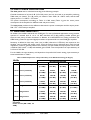
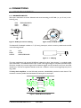
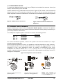
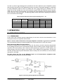
Version 1.0
January 2003
LA48a
OWNERS MANUAL
TABLE OF CONTENTS
LIST OF FIGURES ................................................................................................................................... 2
LIST OF TABLES ..................................................................................................................................... 2
1. APPROVALS........................................................................................................................................ 3
2. WARNINGS......................................................................................................................................... 3
2.1 Explanation of Graphical Symbols ................................................................................................. 3
2.2 WARNING .................................................................................................................................... 3
2.3 CAUTION ..................................................................................................................................... 3
2.4 Important Safety Instructions ........................................................................................................ 3
2.5 User Responsibility ........................................................................................................................ 4
2.5.1 Speaker Damage..................................................................................................................... 4
2.5.2 Speaker Output Hazard ......................................................................................................... 4
2.5.3 Radio Interference .................................................................................................................. 4
3. INTRODUCTION .............................................................................................................................. 6
3.1 Unpacking...................................................................................................................................... 6
3.2 Front Panel .................................................................................................................................... 6
3.3 Rear Panel...................................................................................................................................... 7
4. REAR PANEL FEATURES ................................................................................................................... 8
4.1 Impedance Matching (MLS switch)................................................................................................ 8
4.1.1 MLS Technology Background................................................................................................. 9
4.2 Clip Limiter.................................................................................................................................... 9
5. INSTALLATION................................................................................................................................ 10
5.1 Mounting...................................................................................................................................... 10
5.2 Cooling ........................................................................................................................................ 10
5.3 Operating Voltage ....................................................................................................................... 11
5.3.1 Denmark............................................................................................................................... 11
5.3.2 Switzerland ........................................................................................................................... 11
5.4 Grounding.................................................................................................................................... 11
5.5 Power Consumption ................................................................................................................... 12
5.6 Heat Power Calculation .............................................................................................................. 13
5.7 Gain and Sensitivity...................................................................................................................... 13
6. CONNECTIONS .............................................................................................................................. 14
6.1 Input Connections ....................................................................................................................... 14
6.1.1 Balanced Inputs..................................................................................................................... 14
6.1.2 Unbalanced Inputs ................................................................................................................ 15
6.2 Connecting Speakers................................................................................................................... 15
7. OPERATION..................................................................................................................................... 16
7.1 Operation Modes ........................................................................................................................ 16
7.1.1 Stereo Mode......................................................................................................................... 16
7.1.2 Tandem Mode ...................................................................................................................... 17
7.1.3 Bridged Mono Mode ............................................................................................................ 17
7.2 Operating Precautions................................................................................................................. 17
7.3 Powering Up – Soft Start............................................................................................................. 18
7.4 Input Attenuators ........................................................................................................................ 18
7.5 Indicators ..................................................................................................................................... 18
8. PROTECTION FEATURES............................................................................................................... 19
8.1 Clip Limiter.................................................................................................................................. 19
8.2 Thermal Protection ..................................................................................................................... 19
8.3 VHF Protection............................................................................................................................ 19
8.4 Short Circuit Protection .............................................................................................................. 19
8.5 Automatic Fuse Saver, AFStm-Limiter .......................................................................................... 20
8.6 AC Mains Voltage Protection ...................................................................................................... 20
L-ACOUSTICS LA48a Manual V1.0
27/01/2003
1
8.7 The “AC” LED............................................................................................................................. 20
8.8 DC Protection ............................................................................................................................. 20
9. MAINTENANCE............................................................................................................................... 21
9.1 Troubleshooting .......................................................................................................................... 21
10. WARRANTY.................................................................................................................................... 22
11. Technical Assistance and Service..................................................................................................... 22
LIST OF FIGURES
Figure 1: LA48a Front Panel .................................................................................................................... 6
Figure 2: LA48a Rear Panel ..................................................................................................................... 7
Figure 3: LA48a Rear Panel MLS Switches .............................................................................................. 8
Figure 4: XLR Input Connector Wiring ................................................................................................. 14
Figure 5: Balanced XLR Wiring.............................................................................................................. 14
Figure 6: ¼” TRS Plug ........................................................................................................................... 14
Figure 7: LA48a Rear Panel Detail......................................................................................................... 14
Figure 8: Unbalanced Line Connection ................................................................................................. 15
Figure 9: Balanced Line with Unbalanced Equipment ........................................................................... 15
Figure 10: Loudspeaker Connection Details ......................................................................................... 15
Figure 11: Reverse Polarity Operation for Channel B........................................................................... 16
Figure 12: Bridged Mono Cabling.......................................................................................................... 17
Figure 13: LA48a Front Panel Detail ..................................................................................................... 18
LIST OF TABLES
Table 1: Output Power Ratings and MLS Switch Settings for the LA48a................................................ 8
Table 2: MLS Switch Setting Applications................................................................................................ 9
Table 3: LA48a Current Draw @ 4 ohms............................................................................................. 12
Table 4: LA48a Maximum Output Power versus Mains Input Power .................................................. 12
Table 5: LA48a Output Power and Input Sensitivity versus MLS Switch Setting (32 dB gain).............. 13
Table 6: Maximum Recommended Length for Damping Factor > 20 ................................................. 16
L-ACOUSTICS LA48a Manual V1.0
27/01/2003
2
1. APPROVALS
This equipment conforms to the requirements of the EMC directive 89/336/EEC,
amended by 92/31/EEC and 93/68/EEC, and the requirements of the Low Voltage
Directive 73/23/EEC, amended by 93/68/EEC.
Standard Applied
EMC Emission
EMC Immunity
Electrical Safety
EN55103-1, E3
EN55103-2, E3, with S/N below 1% at normal operation level.
EN60065, Class I
2. WARNINGS
2.1 EXPLANATION OF GRAPHICAL SYMBOLS
The lightning symbol within a triangle is
intended to alert the user to the
presence of un-insulated “dangerous voltage”
within the amplifier’s enclosure that may be of
sufficient magnitude to constitute a risk of
electric shock to humans.
The exclamation point within a triangle is
intended to alert the user to important
operating and service instructions in the
literature accompanying the product.
2.2 WARNING
2.3 CAUTION
To reduce risk of fire or electric shock, do not
expose this apparatus to rain or moisture.
To reduce the risk of fire or electric shock, do
not remove screws. No user-serviceable parts
inside. Refer servicing to qualified service
personnel.
!
2.4 IMPORTANT SAFETY INSTRUCTIONS
Before using your amplifier, be sure to carefully read these operating instructions and
follow the safety suggestions outlined below:
1. Keep this manual for future reference.
2. Heed all warnings.
3. Follow all instructions.
4. Do not use this unit near water. Do not spill water or other liquids into or on the unit. Do not
operate the amplifier while wet or standing in liquid.
5. Clean only with a dry cloth.
!
6. Do not block the air intake or exhaust ports. Install the unit in accordance with the
instructions outlined in this manual.
7. Do not operate the amplifier near heat producing devices such as radiators, heat registers,
stoves or any other apparatus that produces heat.
8. Always operate the unit with the chassis ground wire connected to the electrical safety earth.
Do not defeat the safety purpose of the grounding-type plug. A grounding-type plug has two
pins and a third grounding prong. The third prong is provided for your safety. If the provided
plug does not fit into your outlet, consult an electrician for replacement of the obsolete outlet.
9. Connect only to AC power outlets rated 230-240 V, 50-60 Hz.
L-ACOUSTICS LA48a Manual V1.0
27/01/2003
3
10. Do not use this amplifier if the power cord is broken or frayed. Protect the power cord from
being walked upon or pinched - particularly at the plugs and the point where the power cord
exits from the apparatus.
11. Only use accessories specified by the manufacturer.
!
12. The unit is intended to be mounted in a 19” rack. Follow the mounting instructions outlined in
this manual and always rear support the unit when used in portable applications. When a rack
on wheels is used for portable applications, use caution when moving the loaded rack in order
to avoid injury from tipping over.
13. Unplug this apparatus during lightning storms or when unused for long periods of time.
14. Do not connect an amplifier output in parallel or series with any other amplifier’s output. Do
not connect the amplifier output to any other voltage source, such as a battery, mains source,
or power supply, regardless of whether the amplifier is turned on or off.
15. Do not run the output of any amplifier back into another channel's input.
16. Refer all servicing to qualified service personnel. Servicing is required when the apparatus has
been damaged in any way such as:
• Power supply cord or plug is damaged
• Liquid has been spilled into the unit
• An object has fallen into the unit
• The unit has been exposed to rain or moisture
• The unit does not operate normally
• The unit was dropped or the enclosure is damaged
17. Do not remove top or bottom covers. Removal of the cover will expose hazardous voltages.
There are no serviceable parts inside and removal may void the warranty.
18. An experienced user shall always supervise the use of professional audio equipment, especially
if inexperienced adults or minors are using the equipment.
2.5 USER RESPONSIBILITY
2.5.1 SPEAKER DAMAGE
Your amplifier is very powerful and can be potentially dangerous to both loudspeakers and
humans alike. Loudspeakers can be damaged or destroyed by overpowering, especially with
the high power available from a bridged amplifier. Always check the loudspeaker’s continuous
and peak power handling capabilities. Note: even when using the amplifier’s front panel attenuator to
reduce the gain, it is still possible to reach full output power if the input signal level is high enough.
!
2.5.2 SPEAKER OUTPUT HAZARD
Power amplifiers are capable of producing hazardous output voltages. To avoid electrical
shock, do not touch any exposed speaker wiring while the amplifier is operating. Refer to
Section 6.2 concerning proper connection of loudspeakers.
2.5.3 RADIO INTERFERENCE
A sample of this product has been tested and complies with the limits for the European Electro
Magnetic Compatibility (EMC) directive. These limits are designed to provide reasonable protection
against harmful interference from electrical equipment. This product uses radio frequency energy and
if not used or installed in accordance with these operating instructions, may cause interference to
other equipment such as radio receivers. However, there is no guarantee that interference will not
occur in a particular installation.
L-ACOUSTICS LA48a Manual V1.0
27/01/2003
4
If this equipment does appear to cause harmful interference to radio or television reception, verify by
turning the equipment on and off. The user is then encouraged to try to correct the interference by
one or more of the following measures:
• Reorient or relocate the antenna.
• Increase the separation between the equipment and receiver.
• Connect the equipment to an outlet on a circuit different from that to which the receiver
is connected.
• Check if the affected unit complies with the EMC limits for immunity (CE-labelled). If not,
address the problem with the manufacturer or supplier of the affected unit. All electrical
products sold in the EC must be approved for immunity against electromagnetic fields,
high voltage flashes, and radio interference.
• Consult the dealer or an experienced radio/TV technician for further assistance.
L-ACOUSTICS LA48a Manual V1.0
27/01/2003
5
3. INTRODUCTION
Thank you for purchasing the L-ACOUSTICS LA48a power amplifier. This manual contains important
information on operating your power amplifier correctly and safely. Please take time to read this
manual in order to familiarize yourself with the many advanced features of this amplifier.
3.1 UNPACKING
Carefully open the shipping carton and check for any noticeable damage. Every L-ACOUSTICS
amplifier is tested and inspected before leaving the factory and should arrive in perfect condition. If
found to be damaged, notify the shipping company immediately. Only the consignee may institute a
claim with the carrier for damage incurred during shipping. Be sure to save the carton and packing
materials for the carrier's inspection.
It is also advisable to save the carton and packing material even if the amplifier is undamaged. Should
you ever need to ship the amplifier, always use the original packing.
3.2 FRONT PANEL
6
1
3 4
5
2
6
2
8 9
7
Figure 1: LA48a Front Panel
1. Carry/Protection Handle
Both handles can be used to carry the amplifier and the handles also provide protection for the front
panel. For fixed installation (or when rack front covers are too shallow) the handles may be removed
by unscrewing the retaining bolts behind the front panel.
2. Input Level Attenuators
These controls are used to alter the signal level entering the amplifier. They are calibrated in dB to assist
in the setup of active loudspeaker systems. Input attenuation can also be used to reduce unwanted noise
from the input signal. See Section 7.4 for further details.
3. Over Temperature Protect Indicator
This indicator illuminates if the amplifier tries to operate above its maximum operating temperature
(90°°C). The indicator first comes on as a warning to either turn down the input level or check
amplifier ventilation. Beyond the maximum temperature the amplifier will mute the input signal. When
cooling fans have returned the output heat sinks back to normal operating temperature, the input
signal is un-muted.
4. VHF Protect Indicator
This indicator illuminates when signals above 12 kHz are continuously present at full power at the
output terminals. If this occurs the input signal is muted and the process cycles until the VHF signal is no
longer present.
L-ACOUSTICS LA48a Manual V1.0
27/01/2003
6
5. Clip/Limit Indicator
This indicator signals when the amplifier output is clipping or limiting. There are two different indication
states depending on whether the rear panel clip limiter is engaged (see Sections 4.2, 8.1):
•
•
If the clip limiter is engaged, the Clip/Limit Indicator has a short time constant and illuminates
briefly.
If the clip limiter is not engaged, the Clip/Limit Indicator has an increased time constant and
illuminates for a longer period.
6. Fan Grill Filters
Two grilles with foam filters are located on the front panel in order to prevent dust from entering the
amplifier. The grilles are removed by simply pulling them off, allowing for convenient cleaning of the
filters. Foam filters should be used at all times.
7. Power Switch
Turns the mains power on or off.
8. AC Indicator
Indicates if AC voltage is present. Note: this indicator is located electrically in front of the power switch.
9. AFS Indicator
Indicates if the AFS™ (Automatic Fuse Saver) current limiter is activated.
3.3 REAR PANEL
Gain=32dB
Figure 2: LA48a Rear Panel
1. Output Speaker Connector
The Neutrik® Speakon connector may be unfamiliar to some users. A full description is found in Section
6.2.
2. Minimum Load Selector (MLS™) Switch
These switches are used to select the maximum output power. See Section 4.1.
3. Clip Limiter Switch
Turns the clip limiter on (switch IN position) or off (switch OUT position). See Sections 4.2, 8.1
4. Input Signal Connector
The Neutrik® Combojack features XLR and ¼” TRS phone jacks. (Pin 2 is “hot”, see Section 6.1.1).
5. Link Output
XLR male connector (5) connected in parallel to the female connector (4) for linking the channel to
another input.
6. AC Power Cable
L-ACOUSTICS LA48a Manual V1.0
27/01/2003
7
4. REAR PANEL FEATURES
4.1 IMPEDANCE MATCHING (MLS SWITCH)
The MLS™ (Minimum Load Select) switches located on the rear panel offer power/impedance
matching, allowing the LA48a to power 2 ohm loads without increased heat loss. Please refer to Table
1 to determine the power delivered into a specific load for various MLS switch settings. Note that
higher powers can be achieved utilising higher MLS positions when connected to lower speaker
impedances and as can be seen in Table 1, the LA48a can produce output power in excess of 2000
watts. Essentially, the LA48a amplifier is a power converter and by selecting MLS positions you are
allocating a portion of the available 5800 watts power.
Figure 3: LA48a Rear Panel MLS Switches
Table 1: Output Power Ratings and MLS Switch Settings for the LA48a
LA48a
MLS SWITCH SETTING
-4 dB
-2 dB
260 W
410 W
LOAD CONFIGURATION
16 ohms Stereo (2 channel)
-5 dB
220 W
0 dB
650 W
8 ohms
Stereo (2 channel)
430 W
520 W
820 W
1300 W
4 ohms
Stereo (2 channel)
830 W
1000 W
1600 W
2300 W
2 ohms
Stereo (2 channel)
1660 W
2000 W
2400 W
2900 W
16 ohms Bridged mono
860 W
1040 W
1640 W
2600 W
8 ohms
Bridged mono
1660 W
2000 W
3200 W
4600 W
4 ohms
Bridged mono
3400 W
4000 W
4800 W
5800 W
Power in watts (EIA 1 kHz, 1% THD)
L-ACOUSTICS LA48a Manual V1.0
27/01/2003
8
MLS positions can be different for each channel and a variety of combinations can be selected as seen in
Table 2. There is no risk for amplifier damage since the LA48a is very well protected (even down to 0.3
ohms). However, if uncertain or where time does not allow, use the default position (MLS = 0 dB).
Table 2: MLS Switch Setting Applications
Channel
Impedance
MLS
Power
Comments
A
B
8
8
-2dB
-2dB
820W
820W
Power
reduction
A
B
4
4
0dB
0dB
2300W
2300W
High peak
power
A
B
8
8
0dB
-5dB
1300W
430W
Power
matching
A
B
8
4
-2dB
0dB
820W
2300W
Power
sharing
4.1.1 MLS TECHNOLOGY BACKGROUND
The Problem:
Assume that a power amplifier can deliver 1000 watts into 8 ohms and that it should also be able to
operate into 2 ohms. Theoretically, the power amplifier should deliver 4000 watts into 2 ohms but
very few professional power amplifiers are able to do this since conventional power amplifier designs
are compromises between power dissipation, cost, size etc. Most amplifiers deliver only 70% or less
of their theoretical power into 2 ohms due to resistive losses in the power supply and the use of
current limiting to protect the output semiconductor devices from damage due to too high current.
Current limiting is definitely not the best way to reduce power into low impedance loads because this
type of limiting can produce very nasty distortion and glitches. This occurs since the impedance curve
of a loudspeaker is not a straight line and therefore shows a reactive load to the amplifier. This
reactive load produces back energy that can trigger the current protection and, as a result, produce
glitches in the signal.
The Solution:
The solution is to use a “Constant Power Converter” connected between the power supply and the
linear power amplifier. The Constant Power Converter can produce more current than it takes from
the power supply and in this way overcomes the losses in the power supply when driving low
impedances (such as 2 ohms). Since power is the product of current and voltage, an increase in
current requires a reduction in voltage. This reduction in voltage also causes the dissipation in the
output devices to be lower. The current limit protection can be adjusted for a much higher current,
so that it does not interfere with the requirements dictated by the loudspeaker impedance curve.
4.2 CLIP LIMITER
The LA48a Channel A, B clip limiters prevent dangerous clipped signals from reaching the loudspeaker
and causing damage. When an amplifier is severely overdriven, the output waveform is clipped and
peaks become squared off, causing a reduction in crest factor. In extreme cases, the waveform can
approach that of a square wave. Normally an amplifier is capable of producing far more power under
these conditions than its normal, undistorted rated output power.
The LA48a clip limiter works by monitoring the output and comparing the distortion produced between
the input and output of the amplifier. If the distortion exceeds 1% THD for any reason (voltage or
current clipping), the limiter reduces the input signal proportionally. Once the amplifier comes out of a
L-ACOUSTICS LA48a Manual V1.0
27/01/2003
9
protect condition, the output level has a slow rise time (the effect is like turning the gain up slowly).
Under normal operation, clip limiting circuitry is inaudible.
Note: if the signal is distorted or clipped before it reaches the amplifier, the clip limiter cannot detect
this and will not be activated.
Channel A, B clip limiters can be turned on (or off) by depressing (or pressing) the relevant clip limit
switch. L-ACOUSTICS recommends leaving the clip limiters switched ON (button depressed) at all
times.
Clip Limiter ON = switch depressed (IN position)
Clip Limiter OFF = switch not depressed (OUT position)
5. INSTALLATION
5.1 MOUNTING
The LA48a is two rack units high (2U) and will mount in an EIA-standard 19'' rack. Four mount points
are provided on the front panel of the amplifier for rack mounting.
For permanent installation, the amplifier can be mounted using standard 19'' rack mount rails and/or
slides within the amplifier rack using the four front mount points. Amplifiers may be stacked directly
on top of each other and there is no need for spacing between units. If it is the intention to fill a rack
with amplifiers, we recommend racking is started from the bottom of the rack. It is also
recommended that rear supports are used for amplifiers mounted in the middle of the rack.
For touring or portable sound system applications, it is essential that all LA48a amplifiers are rear
supported in addition to front panel mounting.
Any mechanical damage to LA48A amplifiers used in portable applications without rear support are not
covered under warranty.
For all portable applications, the amplifier should be fixed in the back with a rear support kit (LACOUSTICS part codes: APSUP or MC-RKSUP). The optional accessory MC-RKSUP is designed for
use with the L-ACOUSTICS RK12 amplifier rack. Alternatively, the amplifier support kit APSUP is a
universal rear support kit for any 19'' rack since it is adjustable to accommodate varying rack depths.
Two rear support brackets, two amplifier support brackets, four M4 hex button head screws and four
washers are included in each APSUP kit. The kit integrates the amplifier support bracket with the
amplifier and the rack support bracket with the rack. Depth is adjustable and amplifiers can be
removed from the rack by simply removing the 4 button head screws. APSUP is suitable for use with
all LA amplifiers.
5.2 COOLING
Your amplifier uses a forced air cooling system to maintain a low and even operating temperature. All
fan cooled L-ACOUSTICS amplifiers have front to rear airflow. There are several reasons for this, one
being that there is usually cooler air outside the rack than inside and therefore the amplifiers can run
at higher continuous power levels without thermal problems. Never try to reverse the airflow since
the Intercooler® needs a pressure chamber between the fans and heat sink and this only works in
one direction of the airflow.
Should a heat sink get too hot, its sensing circuit will mute the overheated channel. If the power
supply overheats, another sensing circuit will mute all output channels until the power supply cools
down to a safe operating temperature.
Make sure that there is an adequate air supply in front of the amplifier, and that the rear of the
amplifier has sufficient space to allow the exhaust to escape. If the amplifier is rack-mounted, do not
use covers or doors on the front or rear of the rack.
L-ACOUSTICS LA48a Manual V1.0
27/01/2003
10
For installations with a central cooling system (usually found in fixed installations with a dedicated rack
room) it may be necessary to calculate the maximum heat emission. Please refer to Sections 5.6 and
5.7 concerning Power Consumption and Heat Power Calculation.
5.3 OPERATING VOLTAGE
WARNING!
A label just below the mains cable on the rear of the amplifier indicates the AC mains
voltage for which the amplifier is wired. Connect the power cable only to the AC source
referred to on the label. The warranty will not cover damage caused by connecting to the
wrong type of AC mains.
L-ACOUSTICS switch mode amplifiers use primary switching, i.e. the mains power is rectified directly
before the transformer, which means that the power supply is insensitive to the mains frequency and
will operate from DC to 400 Hz.
The amplifier is supplied with an approved European AC line connector. If this power plug is not
appropriate for your country, it can be cut off and wired to a suitable connector in the following manner:
BLACK or BROWN
LIVE
WHITE or BLUE
NEUTRAL
GREEN or GREEN/YELLOW
EARTH
Once the AC connector is connected to a suitable AC supply, the amplifier can be started with the
power switch. When you power up the amplifier it takes a couple of seconds to check its circuits (this is
known as the soft or slow start sequence), the fans then blow at high speed before going into idle and
the two bottom green LED’s come on to indicate that the output circuits are receiving the correct rail
voltage.
5.3.1 DENMARK
National deviation concerning installation of the LA48a:
Danish safety regulations stipulate the use of an 8 A mains fuse. Since the LA48a uses an internal
primary mains fuse of 15A, the LA48a must be equipped with an industrial mains connector rated for
16 A or, alternatively, be installed to a fixed 16A circuit.
5.3.2 SWITZERLAND
National deviation concerning installation of the LA48a:
Swiss safety regulations stipulate that a type 23 mains connector must be used.
5.4 GROUNDING
There is no ground lift switch or terminal on this amplifier. The signal ground is always floating via a
resistor to chassis and the grounding system is automatic. If a potential above 0.6 V presents itself
between signal ground and chassis ground, a short circuit is introduced between the two, thereby
enabling electrical protection. If a unit in the system is faulty, its mains fuse will blow due to this
automatic ground system.
If you wish to tie the signal ground to chassis, connect the XLR-connector’s shell lug to pin 1. In the
interest of safety never disconnect the earth pin on the AC power cord.
For all units that are CE-approved (radio interference), there is an AC mains filter. This filter needs the
chassis ground for reference, otherwise a current loop is formed via the signal ground.
Use the balanced inputs to avoid hum and interference.
L-ACOUSTICS LA48a Manual V1.0
27/01/2003
11
5.5 POWER CONSUMPTION
There are three ways to define the power/current consumption of a power amplifier:
First, the peak current draw at full output power. Under this condition the power amplifier will trip
the mains breaker within 30 seconds and the amplifier will operate for less than 2 minutes before
thermally limiting. It is therefore meaningless to state the input power at full power since the heat
power at full power will be limited by the protection circuits. In practice, there are no audio program
materials which produce sustained full output power (only sine wave signals for test purposes).
However, if the amplifier is operated at sustained full power (using a sine wave signal) into low
impedances, the LA48a has a mains current limiter called AFS (Automatic Fuse Saver), which will
limit the long-term current draw. Please see Section 8.5 for more detail concerning the AFS-limiter.
It is more useful to state the current draw for different loads and output power levels. The current
draw is stated in Amperes (rms) and this figure corresponds to the value of the mains fuse required.
Table 3: LA48a Current Draw @ 4 ohms
Operating Condition
Current Draw in Amperes (rms)
Idle state (no load)
1 A (rms)
1/8 of full power (- 9 dB)
6 A (rms)
1/3 of full power (-5 dB)
14 A (rms)
Full power (0 dB) at 1 kHz, 1% THD
20 A (rms), AFS limited
Second, the maximum expected average current under worst case conditions, corresponding to 1/3
full power program material according to the FTC standard. At this level the music will be in a state of
constant clip and is therefore the highest power level one can obtain without completely obliterating
the program material.
Third, the normal operating power, as defined by the safety standard IEC 65/ANSI/UL 6500 and used
by a majority of safety agencies. The normal operating power is measured using pink noise, with an
average output power equal to 1/8 of full power. The 1/8 full power specification is as loud as you can
play music while making some attempt to avoid obvious clipping and corresponds to 9 dB of
headroom (which is very low for normal audio program).
Table 4: LA48a Maximum Output Power versus Mains Input Power
MAXIMUM OUTPUT POWER
Load
# of ch
MAINS INPUT POWER
Power
AFS activated
1/3 Power
1/8 Power
(watts)
(watts)
(see note 1)
(see note 2)
Idle
8 ohms
2X
1300
1300
1230
575
105
4 ohms
2X
2300*
1450
1975
900
105
2 ohms
2X
2900*
1850
2950
1290
105
* Will be reduced by AFS protection
note 1
Mean power with music as program source (amplifier driven to clip level)
note 2
Normal music power with 9 dB headroom (IEC standard power rating)
It is recommended that you specify your power distribution service to ensure sufficient current for at
least 1/8 power operation and to upgrade service to meet 1/3 power requirements for heavy duty
demands like discos etc.
L-ACOUSTICS LA48a Manual V1.0
27/01/2003
12
5.6 HEAT POWER CALCULATION
The heat power can be calculated according to the following example:
Consider headroom of at least 9 dB (1/8 of full power) and a 4 ohm load on an amplifier producing
2300 watts per channel. The 1/8 power per channel is then: 2300 / 8 = 287.5 watts; and the total
output power is : 2 x 287.5 = 575 watts.
The power consumption according to Table 4 is 900 watts (Table 4 gives the active power
consumption of the amplifier for different loads and power levels).
The heat power produced is the difference between the power consumption and the output power:
900 - 575 = 325 watts per amplifier.
5.7 GAIN AND SENSITIVITY
As standard, the LA48a is delivered with 32 dB gain. For most professional applications, mixing consoles
operate at a nominal level of +4 to +6 dBu, therefore the 32 dB position provides optimal gain
structure with plenty of fader movement. In addition, all L-ACOUSTICS LLC analog controllers and
OEM factory presets for approved digital processors are optimized for use with 32 dB gain amplifiers.
Sensitivity is defined as how many volts (rms) or dBu (referred to 0.775Vrms) are required at the
amplifier input to obtain full output power. Since the output power delivered varies with the load
impedance, 4 ohms is generally taken as the reference. For the LA48a, full output power into 4 ohms
is 2300 W (MLS switch = 0 dB) and standard gain is 32 dB. This corresponds to an input sensitivity of
2.4 Vrms or 9.9 dBu.
For the LA48a, the input sensitivity will depend on the specific MLS switch setting. Input sensitivity is
summarized below in Table 5.
Table 5: LA48a Output Power and Input Sensitivity versus MLS Switch Setting (32 dB gain)
LA48a
LOAD CONFIGURATION
16 ohms Stereo (2 channel)
-5 dB
220 W
(5.7 dBu)
MLS SWITCH SETTING
-4 dB
-2 dB
260 W
410 W
(6.4 dBu)
(8.4 dBu)
8 ohms Stereo (2 channel)
430 W
(5.6 dBu)
520 W
(6.4 dBu)
820 W
(8.4 dBu)
1300 W
(10.4 dBu)
4 ohms Stereo (2 channel)
830 W
(5.4 dBu)
1000 W
(6.2 dBu)
1600 W
(8.3 dBu)
2300 W
(9.9 dBu)
2 ohms Stereo (2 channel)
1660 W
2000 W
2400 W
2900 W
(5.4 dBu)
(6.2 dBu)
(7.0 dBu)
(7.8 dBu)
860 W
1040 W
1640 W
2600 W
(5.6 dBu)
(6.4 dBu)
(8.4 dBu)
(10.4 dBu)
8 ohms Bridged mono
1660 W
(5.4 dBu)
2000 W
(6.2 dBu)
3200 W
(8.3 dBu)
4600 W
(9.9 dBu)
4 ohms Bridged mono
3400 W
(5.4 dBu)
4000 W
(6.2 dBu)
4800 W
(7.0 dBu)
5800 W
(7.8 dBu)
16 ohms Bridged mono
0 dB
650 W
(10.4 dBu)
[1] Component tolerance
dependent
Power in watts (EIA 1 kHz, 1%
THD)
L-ACOUSTICS LA48a Manual V1.0
27/01/2003
13
6. CONNECTIONS
6.1 INPUT CONNECTIONS
6.1.1 BALANCED INPUTS
XLR Input connectors are active balanced and wired according to IEC 268 (i.e., pin 2 hot) in the
following way:
PIN 1
PIN 2
PIN 3
GROUND/SHIELD
HOT (+)
COLD (-)
Figure 4: XLR Input Connector Wiring
Figure 5: Balanced XLR wiring
The Neutrik® Combojack includes a ¼” (6.3 mm) phone jack, which is wired in parallel with the XLR
in the following manner:
TIP
RING
SLEEVE
HOT
COLD
SHIELD/GROUND
Figure 6: ¼” TRS plug
The input impedance is high enough (20 kOhms, balanced) to allow ”daisy-chaining”, or multiple parallel
input connections. The headroom of the input circuits is also high enough to accept the maximum output
level from virtually any low-level signal source. Balanced signals are less sensitive to AC hum and radio
interference. The source impedance should be less than 1 kOhms in order to avoid high frequency loss in
long cables.
To daisy chain amplifiers, use the XLR-male connector, labeled Link, provided on each channel. This
connector is wired in parallel with the Neutrik® Combo jack on each input.
Gain=32dB
Figure 7: LA48a Rear Panel Detail
L-ACOUSTICS LA48a Manual V1.0
27/01/2003
14
6.1.2 UNBALANCED INPUTS
To connect an unbalanced source, tie pin 3 (ring on TRS jack) to the shield of the connector. Note: if you
leave pin 3 disconnected, you will lose 6 dB.
A better method for using unbalanced sources is shown in Figure 8. This is similar to the connection for
balanced lines, but pin 3 is connected to the shield at the source. The hum and noise rejection for the
cable is equivalent to that for a balanced line. To minimize hum, use balanced inputs whenever possible.
Figure 8: Unbalanced Line Connection
Figure 9: Balanced Line with Unbalanced
Equipment
6.2 CONNECTING SPEAKERS
Speaker connections are made via the two Neutrik® NL4FC Speakon connectors. The Speakon
connector is designed for high power speaker connections and assures correct polarity, locks securely in
place and prevents from shock hazard.
The LA48a power amplifier Speakon connectors are wired in the following manner:
Pin
Pin
Pin
Pin
+1
-1
+2
-2
Channel A
Channel A+
Channel AChannel B+
Channel B-
Channel B
Channel B+
Channel B-
For normal two-channel operation, connect each speaker load across the Channel A, B output
terminals (positive and ground).
Since the Channel A Speakon is bi-wired, it is possible to access both channels on a single connector.
For bi-amped operation, be careful whether Channel A or B outputs are assigned to the LF or HF
component of your active loudspeaker system. As standard, L-ACOUSTICS active 2-way
loudspeakers are cabled as follows: LF +/- = 1+/1- (Ch A) ; HF +/- = 2+/2- (Ch B). Also pay
attention to speaker polarity: loudspeakers connected out of phase degrade sound quality and may be
damaged as a consequence.
Figure 10: Loudspeaker Connection Details
Channel A and B connected via two
separate Speakons
L-ACOUSTICS LA48a Manual V1.0
Channel A and B connected via one
Speakon (for bi-amp applications)
27/01/2003
Bridged mono connection via
Channel A output connector (pins
1+/2-) to loudspeaker (+/-)
15
In order to preserve high damping factor (essential to the sonic qualities of your loudspeaker system
and to prevent overshoot of cone displacement which can result in mechanical damage), it is desirable
to keep loudspeaker cables as short as possible and with a gauge offering low resistance per unit
length. Do not use shielded wire, such as microphone or guitar cable and remember that the speaker
cable robs the power of the amplifier by increasing the load impedance and introducing resistive
power losses (so called I2R losses). The following table provides information regarding the minimum
wire cross-section versus length:
Table 6: Maximum Recommended Length for Damping Factor > 20
Cross Section
Metric (mm2)
2.5
4
6
10
Gauge
Imperial
13
11
8
6
8 ohms
Metric
30 m
50 m
75 m
120 m
Imperial
100 ft
150 ft
225 ft
360 ft
4 ohms
Metric
15 m
25 m
37 m
60 m
Imperial
45 ft
75 ft
110 ft
180 ft
7. OPERATION
7.1 OPERATION MODES
7.1.1 STEREO MODE
In this mode, both channels operate independently of each other and the level attenuators on the
front panel control the respective channel levels.
Never connect either Channel A or B output Speakon terminals to ground or in parallel.
The recommended minimum nominal impedance for stereo operation is 2 ohms per channel.
Note Concerning Bench Test Procedures:
Channel B is always polarity reversed at the input, but this polarity reversal is internally compensated
for by feeding the minus pin on the Channel B output with the positive output voltage. Channel A is
operated with normal polarity. With channel A and B operating in opposite or reverse polarity, the
energy storage in the power supply is more efficient. This is significant for signals below 100 Hz (sub
bass etc) and improves the power bandwidth. Note: Formerly, this was referred to as reverse stereo
operation for the LA48.
For this reason, be sure to use balanced inputs on all measurement equipment (also
oscilloscope probes) if you are bench testing.
Figure 11: Reverse polarity operation for Channel B
L-ACOUSTICS LA48a Manual V1.0
27/01/2003
16
7.1.2 TANDEM MODE
In tandem mode both Channel A and B inputs are linked and receive the same signal. Channel B to A
linking is performed by physically connecting from the Ch A LINK connector (male XLR) to the Ch B
INPUT connector (Neutrik® Combo jack). Both Channel A and B level attenuators are active, allowing
you to set different levels for each channel.
Note: only the inputs are connected in parallel and this is NOT a parallel output mode. Never
connect either output terminal to ground or in parallel.
7.1.3 BRIDGED MONO MODE
Figure 12: Bridged mono cabling
Bridged mono mode is used to deliver both channels' power to a
single load. The nominal impedance of the load must be more
than 4 ohms.
The input signal is applied to Channel A and then linked to the
Channel B input by physically connecting from the Ch A LINK
connector (male XLR) to the Ch B INPUT connector (Neutrik®
Combo jack). Both Channel A and B level attenuators must be at
the same position and it is recommended that they are operated
in the 0 dB (full) position.
Connect the loudspeaker as shown and always use the Channel
A output connector.
7.1.4 BRIDGED MONO MODE FEATURES
Bridged mono mode combines the power of both channels into one speaker. This results in twice the
voltage swing, four times the peak power and just less than three times the full power of a single
channel.
One way to understand the load and power from the amplifier’s perspective in bridged mode is that it
is zero voltage at the center of the voice-coil winding. This is because the coil is driven with positive
voltage at one pole and an equivalent negative voltage at the other pole. So, if an 8 ohm load is
connected in bridged mode, one channel shares one 4 ohm part of the load and the other channel
shares the other 4 ohm part. The power into 4 ohms from an LA48a (MLS at 0 dB) is 2300 W.
Therefore, the total bridged power into the 8 ohm load will be 2 x 2300 = 4600W.
7.2 OPERATING PRECAUTIONS
Never connect either Channel A or B output terminals to ground or to some other output
or input terminal (see also warnings in Section 2.4).
For normal two-channel operation, connect each speaker load across the output channel’s positive
and negative terminals. Pay attention to speaker polarity - loudspeakers connected out of
polarity degrade sound quality and may be damaged as a consequence.
WARNING: To prevent electrical shock, do not operate the amplifier with any of
the conductor portion of the loudspeaker cable exposed.
L-ACOUSTICS LA48a Manual V1.0
27/01/2003
17
•
Refer to Sections 5.1 and 5.2 concerning amplifier mounting and cooling considerations.
•
Make sure that the AC mains voltage is correct and the same as the one printed on the rear
panel of the amplifier. See Sections 5.3-5.7 concerning operating voltage, grounding and
power consumption for more details.
•
Make sure that the power switch is set to “off” before making any input or output
connections or operating the switches on rear panel.
•
Make sure that the switches on the rear panel for clip-limiters and the MLS™ switches are in
the correct position. See Section 7 concerning operation modes, Section 8.1 about clip
limiters and Section 4.1 concerning the MLS switches.
•
It is always a good idea to turn down the gain controls during power-up to prevent speaker
damage in case a high signal is present at the input.
•
Remember the old saying: “amps on last, amps off first”
7.3 POWERING UP – SOFT START
When you power up the amplifier it takes a few seconds to check its circuits (this is known as the soft or
slow start sequence). The fans blow at high speed before going into idle and the two bottom green
LEDs illuminate to show the amplifier is operational.
7.4 INPUT ATTENUATORS
The two input level attenuators on the front panel adjust the signal level for their respective amplifier
channel in all modes. Input level attenuators are calibrated in dB to assist in setting up active loudspeaker
systems or cutting down unwanted noise from the input signal.
In bridged mode, both controls must be in the same position so that the speaker load will be shared
equally between the channels.
7.5 INDICATORS
Figure 13: LA48a Front Panel Detail
The two bottom green ”ON” LED’s indicate that the output circuits are receiving the correct rail
voltage.
The ”-25 dB” LED’s illuminate if the output signal is greater than -25dB (with 0 dB referenced to full
output power). These LED’s also act as signal present indicators.
L-ACOUSTICS LA48a Manual V1.0
27/01/2003
18
The rest of the green LEDs form a bar display indication of output levels from -20 dB to -5 dB.
The “CLIP” LED indicates when the amplifier output is clipping or limiting. It has two different indication
statuses:
•
If the clip limiter is engaged the CLIP LED has a short time constant and illuminates briefly.
•
If the clip limiter is not engaged the CLIP LED has an increased time constant and illuminates for a
longer period.
The remaining TEMP and VHF LEDs indicate if any protection circuits are activated. Protection features
are described in the following section.
8. PROTECTION FEATURES
Each L-ACOUSTICS amplifier has many advanced protection features, protecting both the amplifier and
the loudspeakers connected to it should a fault condition arise. Under normal use these features are
inaudible. All protection circuits are independent.
8.1 CLIP LIMITER
The clip limiter prevents dangerous clipped signals from reaching the loudspeaker and causing damaging.
When an amplifier is severely overdriven, the output waveform is clipped (peaks are squared off) –
reducing the crest factor. In extreme cases, the waveform can approach that of a square wave. An
amplifier is normally capable of producing far more power under these conditions than its normal
undistorted rated output power.
The clip limiter works by monitoring the output and comparing the distortion produced between the
input and output of the amplifier. If the distortion exceeds 1% THD for any reason (voltage or current
clipping), the limiter reduces the input signal proportionally. Once the amplifier comes out of a protect
condition, the output level has a slow rise time - the effect is like turning the gain up slowly. Note: if the
signal is distorted or clipped before it reaches the amplifier, the clip limiter cannot detect it and will not
be activated.
Under normal operation, clip limiting is inaudible. The limiter can be turned On or Off by depressing or
pressing the relevant rear panel clip limit switch. L-ACOUSTICS recommends leaving the clip limiters
switched ON at all times (Channel A, B rear panel clip limiter buttons depressed in the “IN” position).
8.2 THERMAL PROTECTION
If the amplifier is driven hard into a low impedance load, the cooling fans will run at high speed. If this
condition persists, the Temperature indicator(s) will illuminate indicating that the amplifier is about to go
into thermal shutdown.
After five seconds the amplifier will go into thermal protection by muting the input signal. After 15-20
seconds the amplifier will have cooled down enough for the amplifier to come out of shutdown and
operate as normal. If the load conditions remain unchanged the thermal protection will be reinitiated.
Thermal protection starts when the Intercooler® heat sink reaches a temperature above 900 C.
8.3 VHF PROTECTION
If a signal above 12 kHz is detected at the amplifier outputs for more than five seconds at full output
power, VHF protection mutes the input signal. This is indicated on the front panel LED indicator
labeled VHF. After five seconds the outputs will un-mute and return to normal operation, unless the
output signal has remained unchanged, in which case the VHF protection will re-initiate.
8.4 SHORT CIRCUIT PROTECTION
All L-ACOUSTICS amplifiers are completely short circuit-protected. Short circuit protection circuitry
permits very high peak currents, but still holds the output devices within the safe operation area. If a
L-ACOUSTICS LA48a Manual V1.0
27/01/2003
19
short circuit condition is maintained, the affected channel will eventually go into thermal protect cycle
until the short circuit has been removed.
8.5 AUTOMATIC FUSE SAVER, AFS LIMITER
AFS is an abbreviation for Automatic Fuse Saver. The main reason for its presence is to avoid blowing
the mains breaker if a bench test is made at full continuous power. The AFS circuit continuously
monitors the mains current and if the average mains current is too high for a 16 ampere slow blow fuse
(as it can be during some bench test procedures) the AFS limiter will limit the mains current to a safe
level. If the AFS limiter is activated, this will be indicated by the AFS LED on the front panel.
The AFS circuit is a current limiter that limits the mains power current draw to 20 A (230 V) or 40 A
(115V). AFS circuitry has the same characteristics as the mains breaker so it will allow for high peak
currents (that do not significantly raise the long term average power) while limiting the current if the
amplifier draws a high continuous current (this is normally responsible for blowing the mains breaker).
If the AFS circuit is limiting the mains power current or if the regulated power supply goes out of
stabilization, it will be indicated by the AFS LED on the front panel. Note: it is possible for the power
supply will go out of stabilization at low mains voltage in combination with low load impedance during
the start-up sequence. Since 1997, when this feature was introduced, not a single user has reported
that AFS has been activated during music performance, even in high power demanding situations.
During bench test procedures, if the average current draw exceeds what the mains breaker can take
the output power is reduced by 2 dB. Effectively, this is the same as an LA48a being reduced to the
power of an LA24a (but again, not a single user has reported that the AFS has been activated). In
reality this is much better than the mains breaker blowing and the amplifier being turned off - the
listener can hardly hear this since only the headroom will be reduced and if the peaks are around 120
to 130 dB, 2 dB is not noticeable.
8.6 AC MAINS VOLTAGE PROTECTION
If the AC mains voltage is outside the allowed operational voltage (over or under voltage), the power
supply will automatically shut down. Once the mains voltage is above the minimum start voltage and
below its maximum operating voltage the amplifier will restart. It takes a few seconds for the amplifier
to self-check (this is known as the soft or slow start sequence), the gain will slowly and gradually be
increased back to the previously set level and the fans will blow at high speed before going into idle. The
two green ”ON” LEDs indicate when the power supply is operating properly.
8.7 THE “AC” LED
The green AC LED indicates that there is proper mains power present at the incoming mains power
conductors. Electrically, the AC indicator is located in front of the power switch and soft-start circuit,
so it lights up even if the power switch is set to off.
The LA48a has a power relay included in its soft start circuitry that switches the mains instead of the
power switch on the front panel. This method is more reliable and takes less space than the
conventional method of employing huge power switch. However, some governmental safety
standards require that there is an indicator showing that there is power to the circuits if the power is
relay-switched.
8.8 DC PROTECTION
There are two types of DC protection: 1) Fuses on the supply branches of each channel; 2) DC crowbar
protection that shorts the output if more than 10 volts DC are detected on the outputs. Both these
circuits are activated if a DC level is detected on either channel.
L-ACOUSTICS LA48a Manual V1.0
27/01/2003
20
9. MAINTENANCE
Under normal use your power amplifier should provide years of trouble-free service. The only user
maintenance required is to vacuum the front grill periodically.
In some extreme cases it may be necessary for authorized service personnel to clean the inside of the
amplifier. This is usually necessary after prolonged use in environments where cracked-oil smoke
machines are present.
If you are using your amplifier for heavy duty use, e.g. concert touring, it is recommended that you
have your amplifier serviced every 3 years, purely as a preventative measure.
9.1 TROUBLESHOOTING
These are typical things to check if you think your amplifier is faulty:
Fault: No output.
If the output bar graph is functioning there is nothing wrong with the amplifier. The likely cause is an
unsecured Speakon connector (at the amplifier output terminals or loudspeaker).
Check also that VHF protection is not activated. If it is, remove possible high frequency oscillations
from the relevant input.
Fault: The amplifier goes into thermal protection when driven at low level.
Check that nothing causes a short circuit at the amplifier's output, e.g. faulty cabling or a loudspeaker
component short circuit in the voice coil.
Fault: The amplifier goes into protection with the power indicators off.
Check that the AC line voltage is within the amplifier’s operating range:130-265 V @ 230 V (or 65135 V @ 115 V). Over/under-voltage protection may have occurred. If the amplifier is connected by
mistake to a 3 phase supply (415 V), an internal non-resettable fuse or resistor may have blown
(return the amplifier to your supplier for service).
Fault: The amplifier does not respond even after checking above items.
In the unlikely event of a non-user rectifiable fault, return the amplifier to your supplier or an
approved service centre (see Section 11).
L-ACOUSTICS cannot be held responsible for damage or injury as a result of the top or
bottom covers being removed.
L-ACOUSTICS LA48a Manual V1.0
27/01/2003
21
10. WARRANTY
General
This product is manufactured by L-ACOUSTICS and is warranted to be free from defects in
components and factory workmanship under normal use and service for a period of one year from the
date of original purchase.
During the warranty period, L-ACOUSTICS or its nominated agents, will undertake to repair, or at
their option, replace this product at no charge to its owner, if the unit fails to perform as specified,
provided the unit is returned undamaged and shipping is pre-paid to the factory or an authorised
service facility.
This warranty shall be null and void, if the product is subjected to:
1) Repair work or alteration by persons other than those authorised by L-ACOUSTICS or its agents.
2) Shipping accidents, war, civil insurrection, misuse, abuse, operation with incorrect AC voltage,
operation with faulty associated equipment, exposure to inclement weather conditions and normal
wear and tear. Units on which the serial number has been removed or defaced will not be eligible for
warranty service.
L-ACOUSTICS shall not be responsible for any incidental or consequential damages, with respect to
the products warranted.
L-ACOUSTICS reserves the right to make changes or improvements in design or manufacturing,
without assuming any obligation to change or improve products previously manufactured.
This warranty is exclusive and no other warranty is expressed or implied. This warranty does not
affect your statutory rights.
International
Please contact your supplier for this information, as rights and disclaimers may vary from country to
country.
11. TECHNICAL ASSISTANCE AND SERVICE
International
If your L-ACOUSTICS product needs repair, contact your L-ACOUSTICS dealer or distributor, or
contact L-ACOUSTICS by fax or email to obtain the location of the nearest authorized service center.
Factory Service
In the event that your L-ACOUSTICS product needs factory service, you should contact LACOUSTICS’ service department for return instructions and a Return Authorisation number.
Please note for product return
1. Use the original packing.
2. Include a copy of the sales receipt, your name, return address, phone and fax number, email
address and a description of the defect.
3. Mark the Return Authorisation number on the outside of the packing.
4. Ship the product prepaid to:
L-ACOUSTICS
Attention: After Sales Service (SAV)
Parc de la Fontaine de Jouvence
91462 Marcoussis – cedex
France
Telephone:
Fax:
+33 169 63 69 69
+33 169 63 69 64
L-ACOUSTICS LA48a Manual V1.0
Email:
website:
27/01/2003
[email protected]
www.l-acoustics.com
22