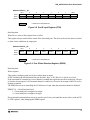
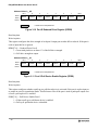
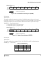
1
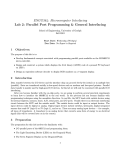
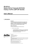
DOCUMENT NUMBER
S12DP256PIMV2/D
MC9S12DP256
Port Integration Module (PIM)
Block User Guide
V02.07
Original Release Date: 31 JUL 2000
Revised: 04 MAR 2002
Motorola, Inc
Motorola reserves the right to make changes without further notice to any products herein to improve reliability, function or
design. Motorola does not assume any liability arising out of the application or use of any product or circuit described herein;
neither does it convey any license under its patent rights nor the rights of others. Motorola products are not designed, intended,
or authorized for use as components in systems intended for surgical implant into the body, or other applications intended to
support or sustain life, or for any other application in which the failure of the Motorola product could create a situation where
personal injury or death may occur. Should Buyer purchase or use Motorola products for any such unintended or unauthorized
application, Buyer shall indemnify and hold Motorola and its officers, employees, subsidiaries, affiliates, and distributors harmless
against all claims, costs, damages, and expenses, and reasonable attorney fees arising out of, directly or indirectly, any claim of
personal injury or death associated with such unintended or unauthorized use, even if such claim alleges that Motorola was
negligent regarding the design or manufacture of the part.
1
PIM_9DP256 Block User Guide V02.07
Revision History
Version Revision Effective
Number
Date
Date
Author
Description of Changes
Initial version for 2nd Barracuda revision started from Integration
Guide PIM_9DP256 V01.00.
Summary of changes:
- Added Port A, B, E, K, and BKGD pin.
- Added MODRR register.
- Moved priority information into Table 2-1 and removed Table 4-1
- Removed reference to IPBus from Block Diagram
V02.00
19 FEB
2001
V02.01
28 MAR
2001
28 MAR
2001
- Updated due to requirements in SRS supplement
V02.02
17 JUL
2001
17 JUL
2001
- 1st official version by Technical Publishing
V02.03
03 AUG
2001
03 AUG
2001
- Capitalized all pin names to match Barracuda DUG.
- Added full register names in memory map table.
- Corrected typo in PPSJ description.
V02.04
11 OCT
2001
11 OCT
2001
- Updated references w.r.t. new family name HCS12.
V02.05
31 OCT
2001
31 OCT
2001
- Minor cleanup.
V02.06
12 NOV
2001
12 NOV
2001
- Removed subsection on unbonded port pins on 80 pin package.
Shall be stated in DUG.
V02.07
04 MAR
2002
04 MAR
2002
- Document format updates.
2
PIM_9DP256 Block User Guide V02.07
Table of Contents
Section 1 Introduction
1.1
1.2
1.3
Overview. . . . . . . . . . . . . . . . . . . . . . . . . . . . . . . . . . . . . . . . . . . . . . . . . . . . . . . . . . . . . .9
Features . . . . . . . . . . . . . . . . . . . . . . . . . . . . . . . . . . . . . . . . . . . . . . . . . . . . . . . . . . . . . .9
Block Diagram . . . . . . . . . . . . . . . . . . . . . . . . . . . . . . . . . . . . . . . . . . . . . . . . . . . . . . . .10
Section 2 External Signal Description
2.1
2.2
Overview. . . . . . . . . . . . . . . . . . . . . . . . . . . . . . . . . . . . . . . . . . . . . . . . . . . . . . . . . . . . .11
Signal properties. . . . . . . . . . . . . . . . . . . . . . . . . . . . . . . . . . . . . . . . . . . . . . . . . . . . . . .11
Section 3 Memory Map and Registers
3.1
Overview. . . . . . . . . . . . . . . . . . . . . . . . . . . . . . . . . . . . . . . . . . . . . . . . . . . . . . . . . . . . .17
3.2
Module Memory Map . . . . . . . . . . . . . . . . . . . . . . . . . . . . . . . . . . . . . . . . . . . . . . . . . . .17
3.3
Register Descriptions . . . . . . . . . . . . . . . . . . . . . . . . . . . . . . . . . . . . . . . . . . . . . . . . . . .18
3.3.1
Port T Registers . . . . . . . . . . . . . . . . . . . . . . . . . . . . . . . . . . . . . . . . . . . . . . . . . . . . .19
3.3.2
Port S Registers . . . . . . . . . . . . . . . . . . . . . . . . . . . . . . . . . . . . . . . . . . . . . . . . . . . . .22
3.3.3
Port M Registers . . . . . . . . . . . . . . . . . . . . . . . . . . . . . . . . . . . . . . . . . . . . . . . . . . . .26
3.3.4
Port P Registers . . . . . . . . . . . . . . . . . . . . . . . . . . . . . . . . . . . . . . . . . . . . . . . . . . . . .31
3.3.5
Port H Registers. . . . . . . . . . . . . . . . . . . . . . . . . . . . . . . . . . . . . . . . . . . . . . . . . . . . .35
3.3.6
Port J Registers . . . . . . . . . . . . . . . . . . . . . . . . . . . . . . . . . . . . . . . . . . . . . . . . . . . . .38
Section 4 Functional Description
4.1
4.1.1
4.1.2
4.1.3
4.1.4
4.1.5
4.1.6
4.2
4.3
4.4
4.4.1
4.5
General. . . . . . . . . . . . . . . . . . . . . . . . . . . . . . . . . . . . . . . . . . . . . . . . . . . . . . . . . . . . . .43
I/O register . . . . . . . . . . . . . . . . . . . . . . . . . . . . . . . . . . . . . . . . . . . . . . . . . . . . . . . . .43
Input register . . . . . . . . . . . . . . . . . . . . . . . . . . . . . . . . . . . . . . . . . . . . . . . . . . . . . . .43
Data direction register . . . . . . . . . . . . . . . . . . . . . . . . . . . . . . . . . . . . . . . . . . . . . . . .43
Reduced drive register . . . . . . . . . . . . . . . . . . . . . . . . . . . . . . . . . . . . . . . . . . . . . . . .44
Pull device enable register . . . . . . . . . . . . . . . . . . . . . . . . . . . . . . . . . . . . . . . . . . . . .44
Polarity select register . . . . . . . . . . . . . . . . . . . . . . . . . . . . . . . . . . . . . . . . . . . . . . . .44
Port T . . . . . . . . . . . . . . . . . . . . . . . . . . . . . . . . . . . . . . . . . . . . . . . . . . . . . . . . . . . . . . .44
Port S . . . . . . . . . . . . . . . . . . . . . . . . . . . . . . . . . . . . . . . . . . . . . . . . . . . . . . . . . . . . . . .45
Port M . . . . . . . . . . . . . . . . . . . . . . . . . . . . . . . . . . . . . . . . . . . . . . . . . . . . . . . . . . . . . . .45
Module Routing Register . . . . . . . . . . . . . . . . . . . . . . . . . . . . . . . . . . . . . . . . . . . . . .45
Port P . . . . . . . . . . . . . . . . . . . . . . . . . . . . . . . . . . . . . . . . . . . . . . . . . . . . . . . . . . . . . . .46
3
PIM_9DP256 Block User Guide V02.07
4.6
Port H . . . . . . . . . . . . . . . . . . . . . . . . . . . . . . . . . . . . . . . . . . . . . . . . . . . . . . . . . . . . . . .48
4.7
Port J . . . . . . . . . . . . . . . . . . . . . . . . . . . . . . . . . . . . . . . . . . . . . . . . . . . . . . . . . . . . . . .48
4.8
Port A, B, E, K, and BKGD pin . . . . . . . . . . . . . . . . . . . . . . . . . . . . . . . . . . . . . . . . . . . .48
4.9
External Pin Descriptions . . . . . . . . . . . . . . . . . . . . . . . . . . . . . . . . . . . . . . . . . . . . . . . .48
4.10 Low Power Options . . . . . . . . . . . . . . . . . . . . . . . . . . . . . . . . . . . . . . . . . . . . . . . . . . . .48
4.10.1 Run Mode. . . . . . . . . . . . . . . . . . . . . . . . . . . . . . . . . . . . . . . . . . . . . . . . . . . . . . . . . .48
4.10.2 Wait Mode . . . . . . . . . . . . . . . . . . . . . . . . . . . . . . . . . . . . . . . . . . . . . . . . . . . . . . . . .48
4.10.3 Stop Mode . . . . . . . . . . . . . . . . . . . . . . . . . . . . . . . . . . . . . . . . . . . . . . . . . . . . . . . . .49
Section 5 Resets
5.1
5.2
General. . . . . . . . . . . . . . . . . . . . . . . . . . . . . . . . . . . . . . . . . . . . . . . . . . . . . . . . . . . . . .51
Reset Initialization . . . . . . . . . . . . . . . . . . . . . . . . . . . . . . . . . . . . . . . . . . . . . . . . . . . . .51
Section 6 Interrupts
6.1
6.2
6.3
General. . . . . . . . . . . . . . . . . . . . . . . . . . . . . . . . . . . . . . . . . . . . . . . . . . . . . . . . . . . . . .53
Interrupt Sources . . . . . . . . . . . . . . . . . . . . . . . . . . . . . . . . . . . . . . . . . . . . . . . . . . . . . .53
Recovery from STOP . . . . . . . . . . . . . . . . . . . . . . . . . . . . . . . . . . . . . . . . . . . . . . . . . . .53
4
PIM_9DP256 Block User Guide V02.07
List of Figures
Figure 1-1
Figure 3-1
Figure 3-2
Figure 3-3
Figure 3-4
Figure 3-5
Figure 3-6
Figure 3-7
Figure 3-8
Figure 3-9
Figure 3-10
Figure 3-11
Figure 3-12
Figure 3-13
Figure 3-14
Figure 3-15
Figure 3-16
Figure 3-17
Figure 3-18
Figure 3-19
Figure 3-20
Figure 3-21
Figure 3-22
Figure 3-23
Figure 3-24
Figure 3-25
Figure 3-26
Figure 3-27
Figure 3-28
Figure 3-29
Figure 3-30
Figure 3-31
Figure 3-32
PIM_9DP256 Block Diagram . . . . . . . . . . . . . . . . . . . . . . . . . . . . . . . . . . . . . . . .10
Port T I/O Register (PTT). . . . . . . . . . . . . . . . . . . . . . . . . . . . . . . . . . . . . . . . . . .19
Port T Input Register (PTIT) . . . . . . . . . . . . . . . . . . . . . . . . . . . . . . . . . . . . . . . .20
Port T Data Direction Register (DDRT) . . . . . . . . . . . . . . . . . . . . . . . . . . . . . . . .20
Port T Reduced Drive Register (RDRT) . . . . . . . . . . . . . . . . . . . . . . . . . . . . . . .21
Port T Pull Device Enable Register (PERT) . . . . . . . . . . . . . . . . . . . . . . . . . . . .21
Port T Polarity Select Register (PPST) . . . . . . . . . . . . . . . . . . . . . . . . . . . . . . . .22
Port S I/O Register (PTS) . . . . . . . . . . . . . . . . . . . . . . . . . . . . . . . . . . . . . . . . . .22
Port S Input Register (PTIS) . . . . . . . . . . . . . . . . . . . . . . . . . . . . . . . . . . . . . . . .23
Port S Data Direction Register (DDRS) . . . . . . . . . . . . . . . . . . . . . . . . . . . . . . . .23
Port S Reduced Drive Register (RDRS) . . . . . . . . . . . . . . . . . . . . . . . . . . . . . . .24
Port S Pull Device Enable Register (PERS) . . . . . . . . . . . . . . . . . . . . . . . . . . . .24
Port S Polarity Select Register (PPSS) . . . . . . . . . . . . . . . . . . . . . . . . . . . . . . . .25
Port S Wired-Or Mode Register (WOMS) . . . . . . . . . . . . . . . . . . . . . . . . . . . . . .25
Port M I/O Register (PTM) . . . . . . . . . . . . . . . . . . . . . . . . . . . . . . . . . . . . . . . . . .26
Port M Input Register (PTIM). . . . . . . . . . . . . . . . . . . . . . . . . . . . . . . . . . . . . . . .26
Port M Data Direction Register (DDRM) . . . . . . . . . . . . . . . . . . . . . . . . . . . . . . .27
Port M Reduced Drive Register (RDRM). . . . . . . . . . . . . . . . . . . . . . . . . . . . . . .27
Port M Pull Device Enable Register (PERM). . . . . . . . . . . . . . . . . . . . . . . . . . . .28
Port M Polarity Select Register (PPSM) . . . . . . . . . . . . . . . . . . . . . . . . . . . . . . .28
Port M Wired-Or Mode Register (WOMM). . . . . . . . . . . . . . . . . . . . . . . . . . . . . .29
Module Routing Register (MODRR) . . . . . . . . . . . . . . . . . . . . . . . . . . . . . . . . . .29
Port P I/O Register (PTP) . . . . . . . . . . . . . . . . . . . . . . . . . . . . . . . . . . . . . . . . . .31
Port P Input Register (PTIP) . . . . . . . . . . . . . . . . . . . . . . . . . . . . . . . . . . . . . . . .31
Port P Data Direction Register (DDRP) . . . . . . . . . . . . . . . . . . . . . . . . . . . . . . . .32
Port P Reduced Drive Register (RDRP) . . . . . . . . . . . . . . . . . . . . . . . . . . . . . . .32
Port P Pull Device Enable Register (PERP) . . . . . . . . . . . . . . . . . . . . . . . . . . . .33
Port P Polarity Select Register (PPSP) . . . . . . . . . . . . . . . . . . . . . . . . . . . . . . . .33
Port P Interrupt Enable Register (PIEP) . . . . . . . . . . . . . . . . . . . . . . . . . . . . . . .34
Port P Interrupt Flag Register (PIFP). . . . . . . . . . . . . . . . . . . . . . . . . . . . . . . . . .34
Port H I/O Register (PTH) . . . . . . . . . . . . . . . . . . . . . . . . . . . . . . . . . . . . . . . . . .35
Port H Input Register (PTIH) . . . . . . . . . . . . . . . . . . . . . . . . . . . . . . . . . . . . . . . .35
Port H Data Direction Register (DDRH). . . . . . . . . . . . . . . . . . . . . . . . . . . . . . . .35
5
PIM_9DP256 Block User Guide V02.07
Figure 3-33
Figure 3-34
Figure 3-35
Figure 3-36
Figure 3-37
Figure 3-38
Figure 3-39
Figure 3-40
Figure 3-41
Figure 3-42
Figure 3-43
Figure 3-44
Figure 3-45
Figure 4-1
Figure 4-2
Figure 4-3
6
Port H Reduced Drive Register (RDRH) . . . . . . . . . . . . . . . . . . . . . . . . . . . . . . .36
Port H Pull Device Enable Register (PERH) . . . . . . . . . . . . . . . . . . . . . . . . . . . .36
Port H Polarity Select Register (PPSH) . . . . . . . . . . . . . . . . . . . . . . . . . . . . . . . .37
Port H Interrupt Enable Register (PIEH) . . . . . . . . . . . . . . . . . . . . . . . . . . . . . . .37
Port H Interrupt Flag Register (PIFH) . . . . . . . . . . . . . . . . . . . . . . . . . . . . . . . . .38
Port J I/O Register (PTJ) . . . . . . . . . . . . . . . . . . . . . . . . . . . . . . . . . . . . . . . . . . .38
Port J Input Register (PTIJ) . . . . . . . . . . . . . . . . . . . . . . . . . . . . . . . . . . . . . . . . .39
Port J Data Direction Register (DDRJ) . . . . . . . . . . . . . . . . . . . . . . . . . . . . . . . .39
Port J Reduced Drive Register (RDRJ) . . . . . . . . . . . . . . . . . . . . . . . . . . . . . . . .40
Port J Pull Device Enable Register (PERJ) . . . . . . . . . . . . . . . . . . . . . . . . . . . . .40
Port J Polarity Select Register (PPSJ). . . . . . . . . . . . . . . . . . . . . . . . . . . . . . . . .41
Port J Interrupt Enable Register (PIEJ) . . . . . . . . . . . . . . . . . . . . . . . . . . . . . . . .41
Port J Interrupt Flag Register (PIFJ) . . . . . . . . . . . . . . . . . . . . . . . . . . . . . . . . . .42
Illustration of I/O pin functionality. . . . . . . . . . . . . . . . . . . . . . . . . . . . . . . . . . . . .44
Interrupt Glitch Filter on Port P, H and J (PPS=0) . . . . . . . . . . . . . . . . . . . . . . . .47
Pulse Illustration . . . . . . . . . . . . . . . . . . . . . . . . . . . . . . . . . . . . . . . . . . . . . . . . .47
PIM_9DP256 Block User Guide V02.07
List of Tables
Table 2-1
Table 3-1
Table 3-2
Table 3-3
Table 3-4
Table 3-5
Table 3-6
Table 3-7
Table 4-1
Table 4-2
Table 5-1
Table 6-1
Pin Functions and Priorities . . . . . . . . . . . . . . . . . . . . . . . . . . . . . . . . . . . . . . . . . .11
PIM_9DP256 Memory Map . . . . . . . . . . . . . . . . . . . . . . . . . . . . . . . . . . . . . . . . . .17
Pin Configuration Summary . . . . . . . . . . . . . . . . . . . . . . . . . . . . . . . . . . . . . . . . . .19
CAN0 Routing . . . . . . . . . . . . . . . . . . . . . . . . . . . . . . . . . . . . . . . . . . . . . . . . . . . .29
CAN4 Routing . . . . . . . . . . . . . . . . . . . . . . . . . . . . . . . . . . . . . . . . . . . . . . . . . . . .30
SPI0 Routing . . . . . . . . . . . . . . . . . . . . . . . . . . . . . . . . . . . . . . . . . . . . . . . . . . . . .30
SPI1 Routing . . . . . . . . . . . . . . . . . . . . . . . . . . . . . . . . . . . . . . . . . . . . . . . . . . . . .30
SPI2 Routing . . . . . . . . . . . . . . . . . . . . . . . . . . . . . . . . . . . . . . . . . . . . . . . . . . . . .30
Implemented modules on derivatives . . . . . . . . . . . . . . . . . . . . . . . . . . . . . . . . . .45
Pulse Detection Criteria . . . . . . . . . . . . . . . . . . . . . . . . . . . . . . . . . . . . . . . . . . . . .47
Port Reset State Summary . . . . . . . . . . . . . . . . . . . . . . . . . . . . . . . . . . . . . . . . . .51
Port Integration Module Interrupt Sources . . . . . . . . . . . . . . . . . . . . . . . . . . . . . . .53
7
PIM_9DP256 Block User Guide V02.07
8
PIM_9DP256 Block User Guide V02.07
Section 1 Introduction
1.1 Overview
The Port Integration Module establishes the interface between the peripheral modules and the I/O pins for
all ports except AD0 and AD1.
This section covers:
•
Port A, B, E, and K related to the core logic and multiplexed bus interface
•
Port T connected to the timer module
•
The serial port S associated with 2 SCI and 1 SPI modules
•
Port M associated with 4 CAN and 1 BDLC module
•
Port P connected to the PWM and 2 SPI modules, which also can be used as an external interrupt
source
•
The standard I/O ports H and J associated with the fifth CAN module and the IIC interface. These
ports can also be used as external interrupt sources.
Each I/O pin can be configured by several registers in order to select data direction and drive strength, to
enable and select pull-up or pull-down resistors. On certain pins also interrupts can be enabled which result
in status flags.
The I/O’s of 2 CAN and all 3 SPI modules can be routed from their default location to determined pins.
The implementation of the Port Integration Module is device dependent.
1.2 Features
A standard port pin has the following minimum features:
•
Input/output selection
•
5V output drive with two selectable drive strengths
•
5V digital and analog input
•
Input with selectable pull-up or pull-down device
Optional features:
•
Open drain for wired-or connections
•
Interrupt inputs with glitch filtering
9
PIM_9DP256 Block User Guide V02.07
1.3 Block Diagram
Figure 1-1 is a block diagram of the PIM_9DP256.
ADDR8/DATA8
ADDR9/DATA9
ADDR10/DATA10
ADDR11/DATA11
ADDR12/DATA12
ADDR13/DATA13
ADDR14/DATA14
ADDR15/DATA15
Port T
Port P
Port S
PS0
PS1
PS2
PS3
PS4
PS5
PS6
PS7
RXD
SCI0 TXD
RXD
MISO
MOSI
SCK
SPI0 SS
SPI0 rout.
SCI1 TXD
BKGD/MODC/TAGHI
XIRQ
IRQ
R/W
LSTRB/TAGLO
ECLK
IPIPE0/MODA
IPIPE1/MODB
NOACC/XCLKS
CORE
XADDR14
XADDR15
XADDR16
XADDR17
XADRR18
XADDR19
ECS/ROMONE
Figure 1-1 PIM_9DP256 Block Diagram
10
PP0
PP1
PP2
PP3
PP4
PP5
PP6
PP7
Port E
ADDR0/DATA0
ADDR1/DATA1
ADDR2/DATA2
ADDR3/DATA3
ADDR4/DATA4
ADDR5/DATA5
ADDR6/DATA6
ADDR7/DATA7
Interrupt Logic
Timer
RXB
TXB BDLC
RXCAN
TXCAN CAN0
RXCAN
TXCAN CAN1
RXCAN
TXCAN CAN2
RXCAN
TXCAN CAN3
MISO
MOSI
SCK
SPI1 SS
MISO
MOSI
SS
SPI2 SCK
PT0
PT1
PT2
PT3
PT4
PT5
PT6
PT7
Port K
Port A
PA0
PA1
PA2
PA3
PA4
PA5
PA6
PA7
Port B
PB0
PB1
PB2
PB3
PB4
PB5
PB6
PB7
Port M
PM2
PM3
PM4
PM5
PM6
PM7
CAN4 rout.
SPI0 rout.
PM1
CAN0 routing
PM0
PWM0
PWM1
PWM2
PWM3
PWM4
PWM5
PWM6
PWM7
IOC0
IOC1
IOC2
IOC3
IOC4
IOC5
IOC6
IOC7
SPI2 rout. SPI1 rout.
PJ7
SCL
IIC
SDA
RXCAN
TXCAN CAN4
PWM
Port J
PJ6
Interrupt Logic
PJ0
PJ1
Interrupt Logic
Port H
PH0
PH1
PH2
PH3
PH4
PH5
PH6
PH7
SPI2 rout. SPI1 rout.
Port Integration Module
BKGD
PE0
PE1
PE2
PE3
PE4
PE5
PE6
PE7
PK0
PK1
PK2
PK3
PK4
PK5
PK7
PIM_9DP256 Block User Guide V02.07
Section 2 External Signal Description
2.1 Overview
This section lists and describes the signals that do connect off-chip.
2.2 Signal properties
Table 2-1 shows all the pins and their functions that are controlled by the PIM_9DP256. If there is more
than one function associated with a pin, the priority is indicated by the position in the table from top
(highest priority) to down (lowest priority).
Table 2-1 Pin Functions and Priorities
Port
Pin Name
Port T
PT[7:0]
PS7
PS6
PS5
PS4
Port S
PS3
PS2
PS1
PS0
Pin Function
IOC[7:0]
GPIO
SS0
Description
Enhanced Capture Timer Channels 7 to 0
General-purpose I/O
GPIO
General-purpose I/O
Serial Peripheral Interface 0 serial clock pin
GPIO
General-purpose I/O
GPIO
MISO0
GPIO
Serial Peripheral Interface 0 slave select output in master mode,
input in slave mode or master mode.
SCK0
MOSI0
Pin
Function
after Reset
Serial Peripheral Interface 0 master out/slave in pin
General-purpose I/O
Serial Peripheral Interface 0 master in/slave out pin
GPIO
General-purpose I/O
TXD1
Serial Communication Interface 1 transmit pin
GPIO
General-purpose I/O
RXD1
Serial Communication Interface 1 receive pin
GPIO
General-purpose I/O
TXD0
Serial Communication Interface 0 transmit pin
GPIO
General-purpose I/O
RXD0
Serial Communication Interface 0 receive pin
GPIO
General-purpose I/O
GPIO
11
PIM_9DP256 Block User Guide V02.07
Port
Pin Name
PM7
PM6
PM5
PM4
Pin Function
TXCAN3
MSCAN3 transmit pin
TXCAN4
MSCAN4 transmit pin
GPIO
General-purpose I/O
RXCAN3
MSCAN3 receive pin
RXCAN4
MSCAN4 receive pin
GPIO
General-purpose I/O
TXCAN2
MSCAN2 transmit pin
TXCAN0
MSCAN0 transmit pin
TXCAN4
MSCAN4 transmit pin
SCK0
Serial Peripheral Interface 0 serial clock pin
GPIO
General-purpose I/O
RXCAN2
MSCAN2 receive pin
RXCAN0
MSCAN0 receive pin
RXCAN4
MSCAN4 receive pin
MOSI0
Port M
PM3
PM2
PM1
PM0
12
Description
Serial Peripheral Interface 0 master out/slave in pin
GPIO
General-purpose I/O
TXCAN1
MSCAN1 transmit pin
TXCAN0
MSCAN0 transmit pin
SS0
Serial Peripheral Interface 0 slave select output in master mode,
input for slave mode or master mode.
GPIO
General-purpose I/O
RXCAN1
MSCAN1 receive pin
RXCAN0
MSCAN0 receive pin
MISO0
Pin
Function
after Reset
Serial Peripheral Interface 0 master in/slave out pin
GPIO
General-purpose I/O
TXCAN0
MSCAN0 transmit pin
TXB
BDLC transmit pin
GPIO
General-purpose I/O
RXCAN0
MSCAN0 receive pin
RXB
BDLC receive pin
GPIO
General-purpose I/O
GPIO
PIM_9DP256 Block User Guide V02.07
Port
Pin Name
PP7
PP6
PP5
PP4
Port P
PP3
PP2
PP1
PP0
Pin Function
Description
PWM7
Pulse Width Modulator channel 7
SCK2
Serial Peripheral Interface 2 serial clock pin
GPIO/KWP7
General-purpose I/O with interrupt
PWM6
Pulse Width Modulator channel 6
SS2
Serial Peripheral Interface 2 slave select output in master mode,
input for slave mode or master mode.
GPIO/KWP6
General-purpose I/O with interrupt
PWM5
Pulse Width Modulator channel 5
MOSI2
Serial Peripheral Interface 2 master out/slave in pin
GPIO/KWP5
General-purpose I/O with interrupt
PWM4
Pulse Width Modulator channel 4
MISO2
Serial Peripheral Interface 2 master in/slave out pin
GPIO/KWP4
General-purpose I/O with interrupt
PWM3
Pulse Width Modulator channel 3
SS1
GPIO
Serial Peripheral Interface 1 slave select output in master mode,
input for slave mode or master mode.
GPIO/KWP3
General-purpose I/O with interrupt
PWM2
Pulse Width Modulator channel 2
SCK1
Serial Peripheral Interface 1 serial clock pin
GPIO/KWP2
General-purpose I/O with interrupt
PWM1
Pulse Width Modulator channel 1
MOSI1
Serial Peripheral Interface 1 master out/slave in pin
GPIO/KWP1
General-purpose I/O with interrupt
PWM0
Pulse Width Modulator channel 0
MISO1
Serial Peripheral Interface 1 master in/slave out pin
GPIO/KWP0
Pin
Function
after Reset
General-purpose I/O with interrupt
13
PIM_9DP256 Block User Guide V02.07
Port
Pin Name
PH7
Pin Function
Description
SS2
Serial Peripheral Interface 2 slave select output in master mode,
input for slave mode or master mode.
GPIO/KWH7
PH6
PH5
PH4
Port H
PH3
SCK2
GPIO/KWH6
MOSI2
GPIO/KWH5
MISO2
GPIO/KWH4
SS1
GPIO/KWH3
PH2
PH1
PH0
SCK1
GPIO/KWH2
MOSI1
GPIO/KWH1
MISO1
GPIO/KWH0
TXCAN4
PJ7
SCL
GPIO/KWJ7
Port J
RXCAN4
PJ6
SDA
General-purpose I/O with interrupt
Serial Peripheral Interface 2 serial clock pin
General-purpose I/O with interrupt
Serial Peripheral Interface 2 master out/slave in pin
General-purpose I/O with interrupt
Serial Peripheral Interface 2 master in/slave out pin
General-purpose I/O with interrupt
Serial Peripheral Interface 1 slave select output in master mode,
input for slave mode or master mode.
GPIO
General-purpose I/O with interrupt
Serial Peripheral Interface 1 serial clock pin
General-purpose I/O with interrupt
Serial Peripheral Interface 1 master out/slave in pin
General-purpose I/O with interrupt
Serial Peripheral Interface 1 master in/slave out pin
General-purpose I/O with interrupt
MSCAN4 transmit pin
Inter Integrated Circuit serial clock line
General-purpose I/O with interrupt
MSCAN4 receive pin
Inter Integrated Circuit serial data line
GPIO/KWJ6
General-purpose I/O with interrupt
PJ[1:0]
GPIO/KWJ[1:0]
General-purpose I/O with interrupt
Port A
PA[7:0]
ADDR[15:8]/
DATA[15:8]/
GPIO
Refer to MEBI in HCS12 Core User Guide.
Port B
PB[7:0]
ADDR[7:0]/
DATA[7:0]/
GPIO
Refer to MEBI in HCS12 Core User Guide.
14
Pin
Function
after Reset
GPIO
PIM_9DP256 Block User Guide V02.07
Port
Pin Name
Pin Function
PE7
NOACC/
XCLKS/
GPIO
PE6
IPIPE1/
MODB/
GPIO
PE5
IPIPE0/
MODA/
GPIO
PE4
ECLK/GPIO
PE3
LSTRB/
TAGLO/
GPIO
PE2
R/W/
GPIO
PE1
IRQ/GPI
PE0
XIRQ/GPI
PK7
ECS/
ROMONE/
GPIO
PK[5:0]
XADDR[19:14]/
GPIO
BKGD
BKGD/
MODC/
TAGHI
Port E
Port K
-
Description
Pin
Function
after Reset
Refer to MEBI in HCS12 Core User Guide.
Refer to MEBI in HCS12 Core User Guide.
Refer to MEBI and BDM in HCS12 Core User Guide.
15
PIM_9DP256 Block User Guide V02.07
16
PIM_9DP256 Block User Guide V02.07
Section 3 Memory Map and Registers
3.1 Overview
This section provides a detailed description of all registers.
3.2 Module Memory Map
Table 3-1 shows the register map of the Port Integration Module.
Table 3-1 PIM_9DP256 Memory Map
Address offset
Use
Access
$00
Port T I/O Register (PTT)
RW
$01
Port T Input Register (PTIT)
R
$02
Port T Data Direction Register (DDRT)
RW
$03
Port T Reduced Drive Register (RDRT)
RW
$04
Port T Pull Device Enable Register (PERT)
RW
$05
Port T Polarity Select Register (PPST)
RW
$06
Reserved
-
$07
Reserved
-
$08
Port S I/O Register (PTS)
RW
$09
Port S Input Register (PTIS)
R
$0A
Port S Data Direction Register (DDRS)
RW
$0B
Port S Reduced Drive Register (RDRS)
RW
$0C
Port S Pull Device Enable Register (PERS)
RW
$0D
Port S Polarity Select Register (PPSS)
RW
$0E
Port S Wired-Or Mode Register (WOMS)
RW
$0F
Reserved
-
$10
Port M I/O Register (PTM)
RW
$11
Port M Input Register (PTIM)
R
$12
Port M Data Direction Register (DDRM)
RW
$13
Port M Reduced Drive Register (RDRM)
RW
$14
Port M Pull Device Enable Register (PERM)
RW
$15
Port M Polarity Select Register (PPSM)
RW
$16
Port M Wired-Or Mode Register (WOMM)
RW
$17
Module Routing Register (MODRR)
RW
$18
Port P I/O Register (PTP)
RW
$19
Port P Input Register (PTIP)
R
$1A
Port P Data Direction Register (DDRP)
RW
$1B
Port P Reduced Drive Register (RDRP)
RW
$1C
Port P Pull Device Enable Register (PERP)
RW
$1D
Port P Polarity Select Register (PPSP)
RW
$1E
Port P Interrupt Enable Register (PIEP)
RW
$1F
Port P Interrupt Flag Register (PIFP)
RW
$20
Port H I/O Register (PTH)
RW
17
PIM_9DP256 Block User Guide V02.07
$21
Port H Input Register (PTIH)
R
$22
Port H Data Direction Register (DDRH)
RW
$23
Port H Reduced Drive Register (RDRH)
RW
$24
Port H Pull Device Enable Register (PERH)
RW
$25
Port H Polarity Select Register (PPSH)
RW
$26
Port H Interrupt Enable Register (PIEH)
RW
$27
Port H Interrupt Flag Register (PIFH)
RW
$28
Port J I/O Register (PTJ)
RW1
$29
Port J Input Register (PTIJ)
R
$2A
Port J Data Direction Register (DDRJ)
RW1
$2B
Port J Reduced Drive Register (RDRJ)
RW1
$2C
Port J Pull Device Enable Register (PERJ)
RW1
$2D
Port J Polarity Select Register (PPSJ)
RW1
$2E
Port J Interrupt Enable Register (PIEJ)
RW1
$2F
Port J Interrupt Flag Register (PIFJ)
RW1
$30 - $3F
Reserved
-
NOTES:
1. Write access not applicable for one or more register bits. Please refer to detailed signal description.
NOTE:
Register Address = Base Address + Address Offset, where the Base Address is
defined at the MCU level and the Address Offset is defined at the module level.
3.3 Register Descriptions
The following table summarizes the effect on the various configuration bits, data direction (DDR), output
level (I/O), reduced drive (RDR), pull enable (PE), pull select (PS) and interrupt enable (IE) for the ports.
The configuration bit PS is used for two purposes:
1. Configure the sensitive interrupt edge (rising or falling), if interrupt is enabled.
2. Select either a pull-up or pull-down device if PE is active.
18
PIM_9DP256 Block User Guide V02.07
Table 3-2 Pin Configuration Summary
DDR
IO
RDR
PE
PS
IE1
Function
Pull Device
Interrupt
0
X
X
0
X
0
Input
Disabled
Disabled
0
X
X
1
0
0
Input
Pull Up
Disabled
0
X
X
1
1
0
Input
Pull Down
Disabled
0
X
X
0
0
1
Input
Disabled
falling edge
0
X
X
0
1
1
Input
Disabled
rising edge
0
X
X
1
0
1
Input
Pull Up
falling edge
0
X
X
1
1
1
Input
Pull Down
rising edge
1
0
0
X
X
0
Output, full drive to 0
Disabled
Disabled
1
1
0
X
X
0
Output, full drive to 1
Disabled
Disabled
1
0
1
X
X
0
Output, reduced drive to 0
Disabled
Disabled
1
1
1
X
X
0
Output, reduced drive to 1
Disabled
Disabled
1
0
0
X
0
1
Output, full drive to 0
Disabled
falling edge
1
1
0
X
1
1
Output, full drive to 1
Disabled
rising edge
1
0
1
X
0
1
Output, reduced drive to 0
Disabled
falling edge
1
1
1
X
1
1
Output, reduced drive to 1
Disabled
rising edge
NOTES:
1. Applicable only on port P, H and J.
NOTE:
All bits of all registers in this module are completely synchronous to internal clocks
during a register read.
3.3.1 Port T Registers
Address Offset: $__00
Read:
Write
ECT:
Reset:
Bit 7
6
5
4
3
2
1
Bit 0
PTT7
PTT6
PTT5
PTT4
PTT3
PTT2
PTT1
PTT0
IOC7
0
IOC6
0
IOC5
0
IOC4
0
IOC3
0
IOC2
0
IOC1
0
IOC0
0
= Reserved or unimplemented
Figure 3-1 Port T I/O Register (PTT)
Read:Anytime.
Write:Anytime.
19
PIM_9DP256 Block User Guide V02.07
If the data direction bits of the associated I/O pins are set to 1, a read returns the value of the port register,
otherwise the value at the pins is read.
Address Offset: $__01
Read:
Write:
Reset:
Bit 7
PTIT7
6
PTIT6
5
PTIT5
4
PTIT4
3
PTIT3
2
PTIT2
1
PTIT1
Bit 0
PTIT0
-
-
-
-
-
-
-
-
= Reserved or unimplemented
Figure 3-2 Port T Input Register (PTIT)
Read:Anytime.
Write:Never, writes to this register have no effect.
This register always reads back the status of the associated pins. This can also be used to detect overload
or short circuit conditions on output pins.
Address Offset: $__02
Read:
Write:
Reset:
Bit 7
6
5
4
3
2
1
Bit 0
DDRT7
DDRT6
DDRT5
DDRT4
DDRT3
DDRT2
DDRT1
DDRT0
0
0
0
0
0
0
0
0
= Reserved or unimplemented
Figure 3-3 Port T Data Direction Register (DDRT)
Read:Anytime.
Write:Anytime.
This register configures each port T pin as either input or output.
The ECT forces the I/O state to be an output for each timer port associated with an enabled output compare.
In these cases the data direction bits will not change.
The DDRT bits revert to controlling the I/O direction of a pin when the associated timer output compare
is disabled.
The timer input capture always monitors the state of the pin.
DDRT[7:0] — Data Direction Port T
1 = Associated pin is configured as output.
0 = Associated pin is configured as input.
Due to internal synchronization circuits, it can take up to 2 bus cycles until the correct value is read on
PTT or PTIT registers, when changing the DDRT register.
20
PIM_9DP256 Block User Guide V02.07
Address Offset: $__03
Read:
Write:
Reset:
Bit 7
6
5
4
3
2
1
Bit 0
RDRT7
RDRT6
RDRT5
RDRT4
RDRT3
RDRT2
RDRT1
RDRT0
0
0
0
0
0
0
0
0
= Reserved or unimplemented
Figure 3-4 Port T Reduced Drive Register (RDRT)
Read:Anytime.
Write:Anytime.
This register configures the drive strength of each port T output pin as either full or reduced. If the port is
used as input this bit is ignored.
RDRT[7:0] — Reduced Drive Port T
1 = Associated pin drives at about 1/3 of the full drive strength.
0 = Full drive strength at output.
Address Offset: $__04
Read:
Write:
Reset:
Bit 7
6
5
4
3
2
1
Bit 0
PERT7
PERT6
PERT5
PERT4
PERT3
PERT2
PERT1
PERT0
0
0
0
0
0
0
0
0
= Reserved or unimplemented
Figure 3-5 Port T Pull Device Enable Register (PERT)
Read:Anytime.
Write:Anytime.
This register configures whether a pull-up or a pull-down device is activated, if the port is used as input.
This bit has no effect if the port is used as output. Out of reset no pull device is enabled.
PERT[7:0] — Pull Device Enable Port T
1 = Either a pull-up or pull-down device is enabled.
0 = Pull-up or pull-down device is disabled.
21
PIM_9DP256 Block User Guide V02.07
Address Offset: $__05
Read:
Write:
Reset:
Bit 7
6
5
4
3
2
1
Bit 0
PPST7
PPST6
PPST5
PPST4
PPST3
PPST2
PPST1
PPST0
0
0
0
0
0
0
0
0
= Reserved or unimplemented
Figure 3-6 Port T Polarity Select Register (PPST)
Read:Anytime.
Write:Anytime.
This register selects whether a pull-down or a pull-up device is connected to the pin.
PPST[7:0] — Pull Select Port T
1 = A pull-down device is connected to the associated port T pin, if enabled by the associated bit in
register PERT and if the port is used as input.
0 = A pull-up device is connected to the associated port T pin, if enabled by the associated bit in
register PERT and if the port is used as input.
3.3.2 Port S Registers
Address Offset: $__08
Read:
Write:
SPI/SCI
Reset:
Bit 7
6
5
4
3
2
1
Bit 0
PTS7
PTS6
PTS5
PTS4
PTS3
PTS2
PTS1
PTS0
SS0
0
SCK0
0
MOSI0
0
MISO0
0
TXD1
0
RXD1
0
TXD0
0
RXD0
0
= Reserved or unimplemented
Figure 3-7 Port S I/O Register (PTS)
Read:Anytime.
Write:Anytime.
If the data direction bits of the associated I/O pins are set to 1, a read returns the value of the port register,
otherwise the value at the pins is read.
The SPI pins (PS[7:4]) configuration is determined by several status bits in the SPI module. Refer to SPI
Block User Guide for details.
The SCI ports associated with transmit pins 3 and 1 are configured as outputs if the transmitter is enabled.
The SCI pins associated with receive pins 2 and 0 are configured as inputs if the receiver is enabled. Refer
to SCI Block User Guide for details.
22
PIM_9DP256 Block User Guide V02.07
Address Offset: $__09
Read:
Write:
Reset:
Bit 7
PTIS7
6
PTIS6
5
PTIS5
4
PTIS4
3
PTIS3
2
PTIS2
1
PTIS1
Bit 0
PTIS0
-
-
-
-
-
-
-
-
= Reserved or unimplemented
Figure 3-8 Port S Input Register (PTIS)
Read:Anytime.
Write:Never, writes to this register have no effect.
This register always reads back the status of the associated pins. This also can be used to detect overload
or short circuit conditions on output pins.
Address Offset:$__0A
Read:
Write:
Reset:
Bit 7
6
5
4
3
2
1
Bit 0
DDRS7
DDRS6
DDRS5
DDRS4
DDRS3
DDRS2
DDRS1
DDRS0
0
0
0
0
0
0
0
0
= Reserved or unimplemented
Figure 3-9 Port S Data Direction Register (DDRS)
Read:Anytime.
Write:Anytime.
This register configures each port S pin as either input or output
If SPI is enabled, the SPI determines the pin direction. Refer to SPI Block User Guide for details.
If the associated SCI transmit or receive channel is enabled this register has no effect on the pins. The pin
is forced to be an output if a SCI transmit channel is enabled, it is forced to be an input if the SCI receive
channel is enabled.
The DDRS bits revert to controlling the I/O direction of a pin when the associated channel is disabled.
DDRS[7:0] — Data Direction Port S
1 = Associated pin is configured as output.
0 = Associated pin is configured as input.
Due to internal synchronization circuits, it can take up to 2 bus cycles until the correct value is read on PTS
or PTIS registers, when changing the DDRS register.
23
PIM_9DP256 Block User Guide V02.07
Address Offset: $__0B
Read:
Write:
Reset:
Bit 7
6
5
4
3
2
1
Bit 0
RDRS7
RDRS6
RDRS5
RDRS4
RDRS3
RDRS2
RDRS1
RDRS0
0
0
0
0
0
0
0
0
= Reserved or unimplemented
Figure 3-10 Port S Reduced Drive Register (RDRS)
Read:Anytime.
Write:Anytime.
This register configures the drive strength of each port S output pin as either full or reduced. If the port is
used as input this bit is ignored.
RDRS[7:0] — Reduced Drive Port S
1 = Associated pin drives at about 1/3 of the full drive strength.
0 = Full drive strength at output.
Address Offset: $__0C
Read:
Write:
Reset:
Bit 7
6
5
4
3
2
1
Bit 0
PERS7
PERS6
PERS5
PERS4
PERS3
PERS2
PERS1
PERS0
1
1
1
1
1
1
1
1
= Reserved or unimplemented
Figure 3-11 Port S Pull Device Enable Register (PERS)
Read:Anytime.
Write:Anytime.
This register configures whether a pull-up or a pull-down device is activated, if the port is used as input or
as output in wired-or (open drain) mode. This bit has no effect if the port is used as push-pull output. Out
of reset a pull-up device is enabled.
PERS[7:0] — Pull Device Enable Port S
1 = Either a pull-up or pull-down device is enabled.
0 = Pull-up or pull-down device is disabled.
24
PIM_9DP256 Block User Guide V02.07
Address Offset: $__0D
Read:
Write:
Reset:
Bit 7
6
5
4
3
2
1
Bit 0
PPSS7
PPSS6
PPSS5
PPSS4
PPSS3
PPSS2
PPSS1
PPSS0
0
0
0
0
0
0
0
0
= Reserved or unimplemented
Figure 3-12 Port S Polarity Select Register (PPSS)
Read:Anytime.
Write:Anytime.
This register selects whether a pull-down or a pull-up device is connected to the pin.
PPSS[7:0] — Pull Select Port S
1 = A pull-down device is connected to the associated port S pin, if enabled by the associated bit in
register PERS and if the port is used as input.
0 = A pull-up device is connected to the associated port S pin, if enabled by the associated bit in
register PERS and if the port is used as input or as wired-or output.
Address Offset: $__0E
Read:
Write:
Reset:
Bit 7
6
5
4
3
2
1
Bit 0
WOMS7
WOMS6
WOMS5
WOMS4
WOMS3
WOMS2
WOMS1
WOMS0
0
0
0
0
0
0
0
0
= Reserved or unimplemented
Figure 3-13 Port S Wired-Or Mode Register (WOMS)
Read:Anytime.
Write:Anytime.
This register configures the output pins as wired-or. If enabled the output is driven active low only
(open-drain). A logic level of “1” is not driven. It applies also to the SPI and SCI outputs and allows a
multipoint connection of several serial modules. This bit has no influence on pins used as inputs.
WOMS[7:0] — Wired-Or Mode Port S
1 = Output buffers operate as open-drain outputs.
0 = Output buffers operate as push-pull outputs.
25
PIM_9DP256 Block User Guide V02.07
3.3.3 Port M Registers
Address Offset: $__10
Read:
Write:
CAN:
BDLC:
Reset
Bit 7
6
5
4
3
2
1
Bit 0
PTM7
PTM6
PTM5
PTM4
PTM3
PTM2
PTM1
PTM0
TXCAN3
RXCAN3
TXCAN2
RXCAN2
TXCAN1
RXCAN1
0
0
0
0
0
0
TXCAN0
TXB
0
RXCAN0
RXB
0
= Reserved or unimplemented
Figure 3-14 Port M I/O Register (PTM)
Read:Anytime.
Write:Anytime.
If the data direction bits of the associated I/O pins are set to 1, a read returns the value of the port register,
otherwise the value at the pins is read.
The CAN function (TXCAN and RXCAN) takes precedence over the general purpose I/O function if the
associated CAN module is enabled. Refer to MSCAN Block Guide for details.
The BDLC function takes precedence over the general purpose I/O function associated if enabled. Refer
to BDLC Block User Guide for details.
If both CAN0 and BDLC are enabled the CAN functionality takes precedence.
Address Offset: $__11
Read:
Write:
Reset:
Bit 7
PTIM7
6
PTIM6
5
PTIM5
4
PTIM4
3
PTIM3
2
PTIM2
1
PTIM1
Bit 0
PTIM0
-
-
-
-
-
-
-
-
= Reserved or unimplemented
Figure 3-15 Port M Input Register (PTIM)
Read:Anytime.
Write:Never, writes to this register have no effect.
This register always reads back the status of the associated pins. This can also be used to detect overload
or short circuit conditions on output pins.
26
PIM_9DP256 Block User Guide V02.07
Address Offset: $__12
Read:
Write:
Reset:
Bit 7
6
5
4
3
2
1
Bit 0
DDRM7
DDRM6
DDRM5
DDRM4
DDRM3
DDRM2
DDRM1
DDRM0
0
0
0
0
0
0
0
0
= Reserved or unimplemented
Figure 3-16 Port M Data Direction Register (DDRM)
Read:Anytime.
Write:Anytime.
This register configures each port M pin as either input or output.
The CAN/BDLC forces the I/O state to be an output for each port line associated with an enabled output
(TXCAN[3:0], TXB). It also forces the I/O state to be an input for each port line associated with an enabled
input (RXCAN[3:0], RXB). In those cases the data direction bits will not change.
The DDRM bits revert to controlling the I/O direction of a pin when the associated peripheral module is
disabled.
DDRM[7:0] — Data Direction Port M
1 = Associated pin is configured as output.
0 = Associated pin is configured as input.
Due to internal synchronization circuits, it can take up to 2 bus cycles until the correct value is read on
PTM or PTIM registers, when changing the DDRM register.
Address Offset: $__13
Read:
Write:
Reset:
Bit 7
6
5
4
3
2
1
Bit 0
RDRM7
RDRM6
RDRM5
RDRM4
RDRM3
RDRM2
RDRM1
RDRM0
0
0
0
0
0
0
0
0
= Reserved or unimplemented
Figure 3-17 Port M Reduced Drive Register (RDRM)
Read:Anytime.
Write:Anytime.
This register configures the drive strength of each port M output pin as either full or reduced. If the port is
used as input this bit is ignored.
RDRM[7:0] — Reduced Drive Port M
1 = Associated pin drives at about 1/3 of the full drive strength.
0 = Full drive strength at output.
27
PIM_9DP256 Block User Guide V02.07
Address Offset: $__14
Read:
Write:
Reset:
Bit 7
6
5
4
3
2
1
Bit 0
PERM7
PERM6
PERM5
PERM4
PERM3
PERM2
PERM1
PERM0
0
0
0
0
0
0
0
0
= Reserved or unimplemented
Figure 3-18 Port M Pull Device Enable Register (PERM)
Read:Anytime.
Write:Anytime.
This register configures whether a pull-up or a pull-down device is activated, if the port is used as input or
wired-or output. This bit has no effect if the port is used as push-pull output. Out of reset no pull device is
enabled.
PERM[7:0] — Pull Device Enable Port M
1 = Either a pull-up or pull-down device is enabled.
0 = Pull-up or pull-down device is disabled.
Address Offset: $__15
Read:
Write:
Reset:
Bit 7
6
5
4
3
2
1
Bit 0
PPSM7
PPSM6
PPSM5
PPSM4
PPSM3
PPSM2
PPSM1
PPSM0
0
0
0
0
0
0
0
0
= Reserved or unimplemented
Figure 3-19 Port M Polarity Select Register (PPSM)
Read:Anytime.
Write:Anytime.
This register selects whether a pull-down or a pull-up device is connected to the pin. If CAN is active a
pull-up device can be activated on the RXCAN[3:0] inputs, but not a pull-down. If BDLC is active a
pull-down device can be activated on the RXB pin but not a pull-up.
PPSM[7:0] — Pull Select Port M
1 = A pull-down device is connected to the associated port M pin, if enabled by the associated bit
in register PERM and if the port is used as a general purpose or BDLC input but not as
RXCAN.
0 = A pull-up device is connected to the associated port M pin, if enabled by the associated bit in
register PERM and if the port is used as general purpose or RXCAN input but not as BDLC.
28
PIM_9DP256 Block User Guide V02.07
Address Offset: $__16
Read:
Write:
Reset:
Bit 7
6
5
4
3
2
1
Bit 0
WOMM7
WOMM6
WOMM5
WOMM4
WOMM3
WOMM2
WOMM1
WOMM0
0
0
0
0
0
0
0
0
= Reserved or unimplemented
Figure 3-20 Port M Wired-Or Mode Register (WOMM)
Read:Anytime.
Write:Anytime.
This register configures the output pins as wired-or. If enabled the output is driven active low only
(open-drain). A logic level of “1” is not driven. It applies also to the CAN and BDLC outputs and allows
a multipoint connection of several serial modules. This bit has no influence on pins used as inputs.
WOMM[7:0] — Wired-Or Mode Port M
1 = Output buffers operate as open-drain outputs.
0 = Output buffers operate as push-pull outputs.
Address Offset: $__17
Read:
Write:
Reset:
Bit 7
0
0
6
5
4
3
2
1
Bit 0
MODRR6
MODRR5
MODRR4
MODRR3
MODRR2
MODRR1
MODRR0
0
0
0
0
0
0
0
= Reserved or unimplemented
Figure 3-21 Module Routing Register (MODRR)
Read:Anytime.
Write:Anytime.
This register configures the re-routing of CAN0, CAN4, SPI0, SPI1, and SPI2 on defined port pins.
MODRR[1:0] — CAN0 Routing
Table 3-3 CAN0 Routing
MODRR[1] MODRR[0] RXCAN0
0
0
PM0
TXCAN0
PM1
0
1
PM21
PM31
1
0
1
1
PM42
PM52
Reserved
29
PIM_9DP256 Block User Guide V02.07
NOTES:
1. Routing to this pin takes effect only if CAN1 disabled
2. Routing to this pin takes effect only if CAN2 disabled
MODRR[3:2] — CAN4 Routing
Table 3-4 CAN4 Routing
MODRR[3] MODRR[2] RXCAN4
0
0
PJ6
TXCAN4
PJ7
0
1
PM41
PM51
1
0
1
1
PM72
PM62
Reserved
NOTES:
1. Routing to this pin takes effect only if CAN2 disabled and CAN0 disabled if routed here
2. Routing to this pin takes effect only if CAN3 disabled
MODRR[4] — SPI0 Routing
Table 3-5 SPI0 Routing
MODRR[4]
0
MISO0
PS4
MOSI0
PS5
SCK0
PS6
SS0
PS7
1
PM21
PM42
PM52
PM31
NOTES:
1. Routing to this pin takes effect only if CAN1 disabled and
CAN0 disabled if routed here
2. Routing to this pin takes effect only if CAN2 disabled and
CAN0 disabled if routed here and CAN4 disabled if routed
here
MODRR[5] — SPI1 Routing
Table 3-6 SPI1 Routing
MODRR[5]
0
1
MISO1
PP0
PH0
MOSI1
PP1
PH1
SCK1
PP2
PH2
SS1
PP3
PH3
MODRR[6] — SPI2 Routing
Table 3-7 SPI2 Routing
MODRR[6]
0
1
30
MISO2
PP4
PH4
MOSI2
PP5
PH5
SCK2
PP7
PH6
SS2
PP6
PH7
PIM_9DP256 Block User Guide V02.07
3.3.4 Port P Registers
Address Offset: $__18
Read:
Write:
PWM:
SPI:
Reset:
Bit 7
6
5
4
3
2
1
Bit 0
PTP7
PTP6
PTP5
PTP4
PTP3
PTP2
PTP1
PTP0
PWM7
SCK2
0
PWM6
SS2
0
PWM5
MOSI2
0
PWM4
MISO2
0
PWM3
SS1
0
PWM2
SCK1
0
PWM1
MOSI1
0
PWM0
MISO1
0
= Reserved or unimplemented
Figure 3-22 Port P I/O Register (PTP)
Read:Anytime.
Write:Anytime.
If the data direction bits of the associated I/O pins are set to 1, a read returns the value of the port register,
otherwise the value at the pins is read.
The PWM function takes precedence over the general purpose I/O function if the associated PWM channel
is enabled. While channels 6-0 are output only if the respective channel is enabled, channel 7 can be PWM
output or input if the shutdown feature is enabled. Refer to PWM Block User Guide for details.
The SPI function takes precedence over the general purpose I/O function associated with if enabled. Refer
to SPI Block User Guide for details.
If both PWM and SPI are enabled the PWM functionality takes precedence.
Address Offset: $__19
Read:
Write:
Reset:
Bit 7
PTIP7
6
PTIP6
5
PTIP5
4
PTIP4
3
PTIP3
2
PTIP2
1
PTIP1
Bit 0
PTIP0
-
-
-
-
-
-
-
-
= Reserved or unimplemented
Figure 3-23 Port P Input Register (PTIP)
Read:Anytime.
Write:Never, writes to this register have no effect.
This register always reads back the status of the associated pins. This can be also used to detect overload
or short circuit conditions on output pins.
31
PIM_9DP256 Block User Guide V02.07
Address Offset: $__1A
Read:
Write:
Reset:
Bit 7
6
5
4
3
2
1
Bit 0
DDRP7
DDRP6
DDRP5
DDRP4
DDRP3
DDRP2
DDRP1
DDRP0
0
0
0
0
0
0
0
0
= Reserved or unimplemented
Figure 3-24 Port P Data Direction Register (DDRP)
Read:Anytime.
Write:Anytime.
This register configures each port P pin as either input or output.
If the associated PWM channel or SPI module is enabled this register has no effect on the pins.
The PWM forces the I/O state to be an output for each port line associated with an enabled PWM7-0
channel. Channel 7 can force the pin to input if the shutdown feature is enabled.
If a SPI module is enabled, the SPI determines the pin direction. Refer to SPI Block User Guide for details.
The DDRM bits revert to controlling the I/O direction of a pin when the associated PWM channel is
disabled.
DDRP[7:0] — Data Direction Port P
1 = Associated pin is configured as output.
0 = Associated pin is configured as input.
Due to internal synchronization circuits, it can take up to 2 bus cycles until the correct value is read on PTP
or PTIP registers, when changing the DDRP register.
Address Offset: $__1B
Read:
Write:
Reset:
Bit 7
6
5
4
3
2
1
Bit 0
RDRP7
RDRP6
RDRP5
RDRP4
RDRP3
RDRP2
RDRP1
RDRP0
0
0
0
0
0
0
0
0
= Reserved or unimplemented
Figure 3-25 Port P Reduced Drive Register (RDRP)
Read:Anytime.
Write:Anytime.
This register configures the drive strength of each port P output pin as either full or reduced. If the port is
used as input this bit is ignored.
RDRP[7:0] — Reduced Drive Port P
1 = Associated pin drives at about 1/3 of the full drive strength.
32
PIM_9DP256 Block User Guide V02.07
0 = Full drive strength at output.
Address Offset: $__1C
Read:
Write:
Reset:
Bit 7
6
5
4
3
2
1
Bit 0
PERP7
PERP6
PERP5
PERP4
PERP3
PERP2
PERP1
PERP0
0
0
0
0
0
0
0
0
= Reserved or unimplemented
Figure 3-26 Port P Pull Device Enable Register (PERP)
Read:Anytime.
Write:Anytime.
This register configures whether a pull-up or a pull-down device is activated, if the port is used as input.
This bit has no effect if the port is used as output. Out of reset no pull device is enabled.
PERP[7:0] — Pull Device Enable Port P
1 = Either a pull-up or pull-down device is enabled.
0 = Pull-up or pull-down device is disabled.
Address Offset: $__1D
Read:
Write:
Reset:
Bit 7
6
5
4
3
2
1
Bit 0
PPSP7
PPSP6
PPSP5
PPSP4
PPSP3
PPSP2
PPSP1
PPSP0
0
0
0
0
0
0
0
0
= Reserved or unimplemented
Figure 3-27 Port P Polarity Select Register (PPSP)
Read:Anytime.
Write:Anytime.
This register serves a dual purpose by selecting the polarity of the active interrupt edge as well as selecting
a pull-up or pull-down device if enabled.
PPSP[7:0] — Polarity Select Port P
1 = Rising edge on the associated port P pin sets the associated flag bit in the PIFP register.A
pull-down device is connected to the associated port P pin, if enabled by the associated bit in
register PERP and if the port is used as input.
0 = Falling edge on the associated port P pin sets the associated flag bit in the PIFP register.A
pull-up device is connected to the associated port P pin, if enabled by the associated bit in
register PERP and if the port is used as input.
33
PIM_9DP256 Block User Guide V02.07
Address Offset: $__1E
Read:
Write:
Reset:
Bit 7
6
5
4
3
2
1
Bit 0
PIEP7
PIEP6
PIEP5
PIEP4
PIEP3
PIEP2
PIEP1
PIEP0
0
0
0
0
0
0
0
0
= Reserved or unimplemented
Figure 3-28 Port P Interrupt Enable Register (PIEP)
Read:Anytime.
Write:Anytime.
This register disables or enables on a per pin basis the edge sensitive external interrupt associated with port
P.
PIEP[7:0] — Interrupt Enable Port P
1 = Interrupt is enabled.
0 = Interrupt is disabled (interrupt flag masked).
Address Offset: $__1F
Read:
Write:
Reset:
Bit 7
6
5
4
3
2
1
Bit 0
PIFP7
PIFP6
PIFP5
PIFP4
PIFP3
PIFP2
PIFP1
PIFP0
0
0
0
0
0
0
0
0
= Reserved or unimplemented
Figure 3-29 Port P Interrupt Flag Register (PIFP)
Read:Anytime.
Write:Anytime.
Each flag is set by an active edge on the associated input pin. This could be a rising or a falling edge based
on the state of the PPSP register. To clear this flag, write “1” to the corresponding bit in the PIFP register.
Writing a “0” has no effect.
PIFP[7:0] — Interrupt Flags Port P
1 = Active edge on the associated bit has occurred (an interrupt will occur if the associated enable
bit is set).
Writing a “1” clears the associated flag.
0 = No active edge pending.
Writing a “0” has no effect.
34
PIM_9DP256 Block User Guide V02.07
3.3.5 Port H Registers
Address Offset:$__20
Read:
Write:
Reset:
Bit 7
6
5
4
3
2
1
Bit 0
PTH7
PTH6
PTH5
PTH4
PTH3
PTH2
PTH1
PTH0
0
0
0
0
0
0
0
0
= Reserved or unimplemented
Figure 3-30 Port H I/O Register (PTH)
Read:Anytime.
Write:Anytime.
If the data direction bits of the associated I/O pins are set to 1, a read returns the value of the port register,
otherwise the value at the pins is read.
Address Offset: $__21
Read:
Write:
Reset:
Bit 7
PTIH7
6
PTIH6
5
PTIH5
4
PTIH4
3
PTIH3
2
PTIH2
1
PTIH1
Bit 0
PTIH0
-
-
-
-
-
-
-
-
= Reserved or unimplemented
Figure 3-31 Port H Input Register (PTIH)
Read:Anytime.
Write:Never, writes to this register have no effect.
This register always reads back the status of the associated pins. This can also be used to detect overload
or short circuit conditions on output pins.
Address Offset: $__22
Read:
Write:
Reset:
Bit 7
6
5
4
3
2
1
Bit 0
DDRH7
DDRH6
DDRH5
DDRH4
DDRH3
DDRH2
DDRH1
DDRH0
0
0
0
0
0
0
0
0
= Reserved or unimplemented
Figure 3-32 Port H Data Direction Register (DDRH)
Read:Anytime.
35
PIM_9DP256 Block User Guide V02.07
Write:Anytime.
This register configures each port H pin as either input or output.
DDRH[7:0] — Data Direction Port H
1 = Associated pin is configured as output.
0 = Associated pin is configured as input.
Due to internal synchronization circuits, it can take up to 2 bus cycles until the correct value is read on
PTH or PTIH registers, when changing the DDRH register.
Address Offset: $__23
Read:
Write:
Reset:
Bit 7
6
5
4
3
2
1
Bit 0
RDRH7
RDRH6
RDRH5
RDRH4
RDRH3
RDRH2
RDRH1
RDRH0
0
0
0
0
0
0
0
0
= Reserved or unimplemented
Figure 3-33 Port H Reduced Drive Register (RDRH)
Read:Anytime.
Write:Anytime.
This register configures the drive strength of each port H output pin as either full or reduced. If the port is
used as input this bit is ignored.
RDRH[7:0] — Reduced Drive Port H
1 = Associated pin drives at about 1/3 of the full drive strength.
0 = Full drive strength at output.
Address Offset: $__24
Read:
Write:
Reset:
Bit 7
6
5
4
3
2
1
Bit 0
PERH7
PERH6
PERH5
PERH4
PERH3
PERH2
PERH1
PERH0
0
0
0
0
0
0
0
0
= Reserved or unimplemented
Figure 3-34 Port H Pull Device Enable Register (PERH)
Read:Anytime.
Write:Anytime.
This register configures whether a pull-up or a pull-down device is activated, if the port is used as input.
This bit has no effect if the port is used as output. Out of reset no pull device is enabled.
PERH[7:0] — Pull Device Enable Port H
36
PIM_9DP256 Block User Guide V02.07
1 = Either a pull-up or pull-down device is enabled.
0 = Pull-up or pull-down device is disabled.
Address Offset: $__25
Read:
Write:
Reset:
Bit 7
6
5
4
3
2
1
Bit 0
PPSH7
PPSH6
PPSH5
PPSH4
PPSH3
PPSH2
PPSH1
PPSH0
0
0
0
0
0
0
0
0
= Reserved or unimplemented
Figure 3-35 Port H Polarity Select Register (PPSH)
Read:Anytime.
Write:Anytime.
This register serves a dual purpose by selecting the polarity of the active interrupt edge as well as selecting
a pull-up or pull-down device if enabled.
PPSH[7:0] — Polarity Select Port H
1 = Rising edge on the associated port H pin sets the associated flag bit in the PIFH register.
A pull-down device is connected to the associated port H pin, if enabled by the associated bit
in register PERH and if the port is used as input.
0 = Falling edge on the associated port H pin sets the associated flag bit in the PIFH register.
A pull-up device is connected to the associated port H pin, if enabled by the associated bit in
register PERH and if the port is used as input.
Address Offset: $__26
Read:
Write:
Reset:
Bit 7
6
5
4
3
2
1
Bit 0
PIEH7
PIEH6
PIEH5
PIEH4
PIEH3
PIEH2
PIEH1
PIEH0
0
0
0
0
0
0
0
0
= Reserved or unimplemented
Figure 3-36 Port H Interrupt Enable Register (PIEH)
Read:Anytime.
Write:Anytime.
This register disables or enables on a per pin basis the edge sensitive external interrupt associated with port
H.
PIEH[7:0] — Interrupt Enable Port H
1 = Interrupt is enabled.
0 = Interrupt is disabled (interrupt flag masked).
37
PIM_9DP256 Block User Guide V02.07
Address Offset: $__27
Read:
Write:
Reset:
Bit 7
6
5
4
3
2
1
Bit 0
PIFH7
PIFH6
PIFH5
PIFH4
PIFH3
PIFH2
PIFH1
PIFH0
0
0
0
0
0
0
0
0
= Reserved or unimplemented
Figure 3-37 Port H Interrupt Flag Register (PIFH)
Read:Anytime.
Write:Anytime.
Each flag is set by an active edge on the associated input pin. This could be a rising or a falling edge based
on the state of the PPSH register. To clear this flag, write “1” to the corresponding bit in the PIFH register.
Writing a “0” has no effect.
PIFH[7:0] — Interrupt Flags Port H
1 = Active edge on the associated bit has occurred (an interrupt will occur if the associated enable
bit is set).
Writing a “1” clears the associated flag.
0 = No active edge pending.
Writing a “0” has no effect.
3.3.6 Port J Registers
Address Offset: $__28
Read:
Write:
CAN:
IIC:
Reset:
Bit 7
6
PTJ7
PTJ6
TXCAN4
SCL
0
RXCAN4
SDA
0
5
0
4
0
3
0
2
0
-
-
-
-
1
Bit 0
PTJ1
PTJ0
0
0
= Reserved or unimplemented
Figure 3-38 Port J I/O Register (PTJ)
Read:Anytime.
Write:Anytime.
If the data direction bits of the associated I/O pins are set to 1, a read returns the value of the port register,
otherwise the value at the pins is read.
The CAN function (TXCAN and RXCAN) takes precedence over the general purpose I/O function if the
associated CAN module is enabled. Refer to MSCAN Block Guide for details.
38
PIM_9DP256 Block User Guide V02.07
The IIC function takes precedence over the general purpose I/O function associated with if enabled.
If both CAN4 and IIC are enabled the CAN functionality takes precedence. Refer to IIC Block User Guide
for details.
If the IIC module is enabled the SDA and SCL outputs are configured as open-drain outputs.
Address Offset: $__29
Read:
Write:
Reset:
Bit 7
PTIJ7
6
PTIJ6
5
0
4
0
3
0
2
0
1
PTIJ1
Bit 0
PTIJ0
-
-
-
-
-
-
-
-
= Reserved or unimplemented
Figure 3-39 Port J Input Register (PTIJ)
Read:Anytime.
Write:Never, writes to this register have no effect.
This register always reads back the status of the associated pins. This can be used to detect overload or
short circuit conditions on output pins.
Address Offset: $__2A
Read:
Write:
Reset:
Bit 7
6
DDRJ7
DDRJ6
0
0
5
0
4
0
3
0
2
0
-
-
-
-
1
Bit 0
DDRJ1
DDRJ0
0
0
= Reserved or unimplemented
Figure 3-40 Port J Data Direction Register (DDRJ)
Read:Anytime.
Write:Anytime.
This register configures each port J pin as either input or output.
The CAN forces the I/O state to be an output on PJ7 (TXCAN4) and an input on pin PJ6 (RXCAN4). The
IIC takes control of the I/O if enabled. In these cases the data direction bits will not change. The DDRJ
bits revert to controlling the I/O direction of a pin when the associated peripheral module is disabled.
DDRJ[7:6][1:0] — Data Direction Port J
1 = Associated pin is configured as output.
0 = Associated pin is configured as input.
Due to internal synchronization circuits, it can take up to 2 bus cycles until the correct value is read on PTJ
or PTIJ registers, when changing the DDRJ register.
39
PIM_9DP256 Block User Guide V02.07
Address Offset: $__2B
Read:
Write:
Reset:
Bit 7
6
RDRJ7
RDRJ6
0
0
5
0
4
0
3
0
2
0
-
-
-
-
1
Bit 0
RDRJ1
RDRJ0
0
0
= Reserved or unimplemented
Figure 3-41 Port J Reduced Drive Register (RDRJ)
Read:Anytime.
Write:Anytime.
This register configures the drive strength of each port J output pin as either full or reduced. If the port is
used as input this bit is ignored.
RDRJ[7:6][1:0] — Reduced Drive Port J
1 = Associated pin drives at about 1/3 of the full drive strength.
0 = Full drive strength at output.
Address Offset: $__2C
Read:
Write:
Reset:
Bit 7
6
PERJ7
PERJ6
1
1
5
0
4
0
3
0
2
0
-
-
-
-
1
Bit 0
PERJ1
PERJ0
1
1
= Reserved or unimplemented
Figure 3-42 Port J Pull Device Enable Register (PERJ)
Read:Anytime.
Write:Anytime.
This register configures whether a pull-up or a pull-down device is activated, if the port is used as input or
as wired-or output. This bit has no effect if the port is used as push-pull output. Out of reset a pull-up device
is enabled.
PERJ[7:6][1:0] — Pull Device Enable Port J
1 = Either a pull-up or pull-down device is enabled.
0 = Pull-up or pull-down device is disabled.
40
PIM_9DP256 Block User Guide V02.07
Address Offset: $__2D
Read:
Write:
Reset:
Bit 7
6
PPSJ7
PPSJ6
0
0
5
0
4
0
3
0
2
0
-
-
-
-
1
Bit 0
PPSJ1
PPSJ0
0
0
= Reserved or unimplemented
Figure 3-43 Port J Polarity Select Register (PPSJ)
Read:Anytime.
Write:Anytime.
This register serves a dual purpose by selecting the polarity of the active interrupt edge as well as selecting
a pull-up or pull-down device if enabled.
PPSJ[7:6][1:0] — Polarity Select Port J
1 = Rising edge on the associated port J pin sets the associated flag bit in the PIFJ register.
A pull-down device is connected to the associated port J pin, if enabled by the associated bit in
register PERJ and if the port is used as input.
0 = Falling edge on the associated port J pin sets the associated flag bit in the PIFJ register.
A pull-up device is connected to the associated port J pin, if enabled by the associated bit in
register PERJ and if the port is used as general purpose input or as IIC port.
Address Offset: $__2E
Read:
Write:
Reset:
Bit 7
6
PIEJ7
PIEJ6
0
0
5
0
4
0
3
0
2
0
-
-
-
-
1
Bit 0
PIEJ1
PIEJ0
0
0
= Reserved or unimplemented
Figure 3-44 Port J Interrupt Enable Register (PIEJ)
Read:Anytime.
Write:Anytime.
This register disables or enables on a per pin basis the edge sensitive external interrupt associated with port
J.
PIEJ[7:6][1:0] — Interrupt Enable Port J
1 = Interrupt is enabled.
0 = Interrupt is disabled (interrupt flag masked).
41
PIM_9DP256 Block User Guide V02.07
Address Offset: $__2F
Read:
Write:
Reset:
Bit 7
6
PIFJ7
PIFJ6
0
0
5
0
4
0
3
0
2
0
-
-
-
-
1
Bit 0
PIFJ1
PIFJ0
0
0
= Reserved or unimplemented
Figure 3-45 Port J Interrupt Flag Register (PIFJ)
Read:Anytime.
Write:Anytime.
Each flag is set by an active edge on the associated input pin. This could be a rising or a falling edge based
on the state of the PPSJ register. To clear this flag, write “1” to the corresponding bit in the PIFJ register.
Writing a “0” has no effect.
PIFJ[7:6][1:0] — Interrupt Flags Port J
1 = Active edge on the associated bit has occurred (an interrupt will occur if the associated enable
bit is set).
Writing a “1” clears the associated flag.
0 = No active edge pending.
Writing a “0” has no effect.
42
PIM_9DP256 Block User Guide V02.07
Section 4 Functional Description
4.1 General
Each pin can act as general purpose I/O. In addition the pin can act as an output from a peripheral module
or an input to a peripheral module.
A set of configuration registers is common to all ports. All registers can be written at any time, however a
specific configuration might not become active.
Example:
Selecting a pull-up resistor. This resistor does not become active while the port is used as a push-pull
output.
4.1.1 I/O register
This register holds the value driven out to the pin if the port is used as a general purpose I/O.
Writing to this register has only an effect on the pin if the port is used as general purpose output. When
reading this address, the value of the pins is returned if the data direction register bits are set to 0.
If the data direction register bits are set to 1, the contents of the I/O register is returned. This is independent
of any other configuration (Figure 4-1).
4.1.2 Input register
This is a read-only register and always returns the value of the pin (Figure 4-1).
4.1.3 Data direction register
This register defines whether the pin is used as an input or an output.
If a peripheral module controls the pin the contents of the data direction register is ignored (Figure 4-1).
43
PIM_9DP256 Block User Guide V02.07
PTI
0
1
PT
0
PAD
1
DDR
0
1
data out
Module
output enable
module enable
Figure 4-1 Illustration of I/O pin functionality
4.1.4 Reduced drive register
If the port is used as an output the register allows the configuration of the drive strength.
4.1.5 Pull device enable register
This register turns on a pull-up or pull-down device.
It becomes only active if the pin is used as an input or as a wired-or output.
4.1.6 Polarity select register
This register selects either a pull-up or pull-down device if enabled.
It becomes only active if the pin is used as an input. A pull-up device can be activated if the pin is used as
a wired-or output.
4.2 Port T
This port is associated with the Enhanced Capture Timer module.
In all modes, port T pins PT[7:0] can be used for either general-purpose I/O, or with the channels of the
Enhanced Capture Timer.
During reset, port T pins are configured as high-impedance inputs.
44
PIM_9DP256 Block User Guide V02.07
4.3 Port S
This port is associated with the serial SCI and SPI modules.
In all modes, port S pins PS[7:0] can be used either for general-purpose I/O, or with the SCI and SPI
subsystems.
During reset, port S pins are configured as inputs with pull-up.
The SPI pins can be re-routed. Refer to 4.4.1 Module Routing Register.
4.4 Port M
This port is associated with the J1850 and 4 CAN modules.
In all modes, port M pins PM[7:0] can be used for either general purpose I/O, or with the CAN and J1850
subsystems.
By default, pins PM0 and PM1 are shared between the CAN0 and the BDLC (J1850) module. If CAN0 is
enabled the pins become CAN transmit and receive pins. If BLDC is enabled and CAN0 is disabled, pins
become active BDLC transmit and receive pins.
During reset, port M pins are configured as high-impedance inputs.
The CAN pins can be re-routed. Refer to 4.4.1 Module Routing Register.
4.4.1 Module Routing Register
This register allows to re-route the CAN0, CAN4, SPI0, SPI1, and SPI2 pins to predefined pins.
NOTE:
The purpose of the Module Routing Register is to provide maximum flexibility for
future derivatives of the MC9S12DP256 with a lower number of MSCAN and SPI
modules.
Table 4-1 Implemented modules on derivatives
MSCAN modules
SPI modules
Number of modules
CAN0
CAN1
CAN2
CAN4
SPI0
SPI1
SPI2
4
X
X
X
X
-
-
-
3
X
X
-
X
X
X
X
2
X
-
-
X
X
X
-
1
X
-
-
-
X
-
-
The CAN0 transmit and receive pin can be routed to PM[3:2] or PM[5:4] if CAN1 and CAN2 are disabled,
respectively. PM[5:4] or PM[7:6] can be taken by CAN4, if CAN2 and CAN3 are disabled, respectively.
45
PIM_9DP256 Block User Guide V02.07
CAN0 has priority over CAN4 if both modules are trying to access PM[5:4] at the same time and CAN2
is not enabled.
The SPI0 pins can be routed to PM[5:2] if no other module uses these pins. If the SPI0 module is routed
on PM[5:4] and used in bidirectional master mode with disabled SS output, PM[3:2] are free to be used
with CAN or GPIO.
The SPI1 and SPI2 pins can be routed to PH[3:0] and PH[7:4], respectively.
4.5 Port P
This port is associated with the PWM and 2 SPI modules.
In all modes, port P pins PP[7:0] can be used for either general purpose I/O, or with the PWM and SPI
subsystems.
The pins are shared between the PWM channels and the SPI1 and SPI2 modules. If the PWM is enabled
the pins become PWM output channels with the exception of pin 7 which can be PWM input or output. If
SPI1 or SPI2 are enabled and PWM is disabled, the respective pin configuration is determined by several
status bits in the SPI modules.
During reset, port P pins are configured as high-impedance inputs.
The SPI pins can be re-routed. Refer to 4.4.1 Module Routing Register.
Port P offers 8 I/O pins with edge triggered interrupt capability in wired-or fashion. The interrupt enable
as well as the sensitivity to rising or falling edges can be individually configured on per pin basis. All 8
bits/pins share the same interrupt vector. Interrupts can be used with the pins configured as inputs or
outputs.
An interrupt is generated when a bit in the port interrupt flag register and its corresponding port interrupt
enable bit are both set. This external interrupt feature is capable to wake up the CPU when it is in STOP
or WAIT mode.
A digital filter on each pin prevents pulses (Figure 4-3) shorter than a specified time from generating an
interrupt. The minimum time varies over process conditions, temperature and voltage (Figure 4-2 and
Table 4-2).
46
PIM_9DP256 Block User Guide V02.07
Glitch, filtered out, no interrupt flag set
Valid pulse, interrupt flag set
tifmin
tifmax
Figure 4-2 Interrupt Glitch Filter on Port P, H and J (PPS=0)
Table 4-2 Pulse Detection Criteria
Mode
Pulse
STOP1
STOP
Unit
Ignored
Uncertain
Valid
tpulse <= 3
3 < tpulse
bus clocks
<4
bus clocks
tpulse >= 4
bus clocks
Unit
tpulse <= 3.2
µs
< 10
µs
tpulse >= 10
µs
3.2 < tpulse
NOTES:
1. These values include the spread of the oscillator frequency over temperature,
voltage and process.
tpulse
Figure 4-3 Pulse Illustration
A valid edge on an input is detected if 4 consecutive samples of a passive level are followed by 4
consecutive samples of an active level directly or indirectly.
The filters are continuously clocked by the bus clock in RUN and WAIT mode. In STOP mode the clock
is generated by a single RC oscillator in the Port Integration Module. To maximize current saving the RC
oscillator runs only if the following condition is true on any pin:
47
PIM_9DP256 Block User Guide V02.07
Sample count <= 4 and port interrupt enabled (PIE=1) and port interrupt flag not set (PIF=0).
4.6 Port H
Port H offers 8 I/O ports with the same interrupt features as port P.
During reset, port H pins are configured as high-impedance inputs.
Port H pins can be used with the routed SPI modules. Refer to 4.4.1 Module Routing Register.
4.7 Port J
This port is associated with the fifth CAN and the IIC module.
In all modes, port J pins PJ[7:6] and PJ[1:0] can be used for either general purpose I/O, or with the CAN
and IIC subsystems.
By default, pins PJ6 and PJ7 are shared between the CAN4 and the IIC module. If CAN4 is enabled the
pins become CAN transmit and receive pins. If IIC is enabled and CAN4 is disabled, the pins become IIC
open-drain output pins.
During reset, port J pins are configured as inputs with pull-up.
The CAN pins can be re-routed. Refer to 4.4.1 Module Routing Register.
Port J offers 4 I/O ports with the same interrupt features as port P.
4.8 Port A, B, E, K, and BKGD pin
All port and pin logic is located in the core module. Refer to S12_mebi Block User Guide for details.
4.9 External Pin Descriptions
All ports start up as general purpose inputs on reset.
4.10 Low Power Options
4.10.1 Run Mode
No low power options exist for this module in run mode.
4.10.2 Wait Mode
No low power options exist for this module in wait mode.
48
PIM_9DP256 Block User Guide V02.07
4.10.3 Stop Mode
All clocks are stopped. There are asynchronous paths to generate interrupts from STOP on port P, H and J.
49
PIM_9DP256 Block User Guide V02.07
50
PIM_9DP256 Block User Guide V02.07
Section 5 Resets
5.1 General
The reset values of all registers are given in section 3.3 Register Descriptions.
5.2 Reset Initialization
All registers including the data registers get set/reset asynchronously. Table 5-1 summarizes the port
properties after reset initialization.
Table 5-1 Port Reset State Summary
Reset States
Port
Data
Direction
Pull Mode
Red. Drive
Wired-Or
Mode
Interrupt
T
input
hiz
disabled
n/a
n/a
S
input
pull-up
disabled
disabled
n/a
M
input
hiz
disabled
disabled
n/a
P
input
hiz
disabled
n/a
disabled
H
input
hiz
disabled
n/a
disabled
J
input
pull-up
disabled
n/a
disabled
A
B
Refer to MEBI in HCS12 Core User Guide for details.
E
K
BKGD pin
Refer to BDM in HCS12 Core User Guide for details.
51
PIM_9DP256 Block User Guide V02.07
52
PIM_9DP256 Block User Guide V02.07
Section 6 Interrupts
6.1 General
Port P, H and J generate a separate edge sensitive interrupt if enabled.
6.2 Interrupt Sources
Interrupt Source
Interrupt
Flag
Local Enable
Global (CCR)
Mask
Port P
PIFP[7:0]
PIEP[7:0]
I Bit
Port H
PIFH[7:0]
PIEH[7:0]
I Bit
Port J
PIFJ[7:6]
PIFJ[1:0]
PIFJ[7:6]
PIFJ[1:0]
I Bit
Table 6-1 Port Integration Module Interrupt Sources
NOTE:
Vector addresses and their relative interrupt priority are determined at the MCU
level.
6.3 Recovery from STOP
The PIM_9DP256 can generate wake-up interrupts from STOP on port P, H and J. For other sources of
external interrupts refer to the respective Block User Guides.
53
PIM_9DP256 Block User Guide V02.07
54
PIM_9DP256 Block User Guide V02.07
User Guide End Sheet
55
PIM_9DP256 Block User Guide V02.07
FINAL PAGE OF
56
PAGES
56