1
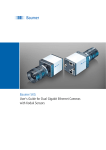
Baumer HXC Series
User's Guide for CameraLink® Cameras with CMOSIS Sensors
Table of Contents
1. General Information������������������������������������������������������������������������������������������������� 4
2. General safety instructions������������������������������������������������������������������������������������� 5
3. Intended Use������������������������������������������������������������������������������������������������������������� 5
4. General Description������������������������������������������������������������������������������������������������� 5
5. Camera Models��������������������������������������������������������������������������������������������������������� 6
5.1 HXC – Cameras with C-Mount�������������������������������������������������������������������������������� 6
5.2 HXC-F – Cameras with F-Mount����������������������������������������������������������������������������� 7
6. Product Specifications�������������������������������������������������������������������������������������������� 8
6.1 Sensor Specifications��������������������������������������������������������������������������������������������� 8
6.1.1 Quantum Efficiency for Baumer HXC Cameras����������������������������������������������� 8
6.1.2 Shutter�������������������������������������������������������������������������������������������������������������� 8
6.1.3 Digitization Taps����������������������������������������������������������������������������������������������� 9
6.2 Timings������������������������������������������������������������������������������������������������������������������ 10
6.2.1 Free Running Mode���������������������������������������������������������������������������������������� 10
6.2.2 Trigger Mode���������������������������������������������������������������������������������������������������11
6.3 Field of View Position�������������������������������������������������������������������������������������������� 15
6.4 Process- and Data Interface��������������������������������������������������������������������������������� 16
6.4.1 Pin-Assignment CameraLink® Interface��������������������������������������������������������� 16
6.4.2 Pin-Assignment Power Supply and Digital IOs���������������������������������������������� 17
6.4.3 LED Signaling������������������������������������������������������������������������������������������������� 17
6.5 Environmental Requirements�������������������������������������������������������������������������������� 18
6.5.1 Temperature and Humidity Range������������������������������������������������������������������ 18
6.5.2 Heat Transmission������������������������������������������������������������������������������������������ 18
6.5.3 Mechanical Tests�������������������������������������������������������������������������������������������� 19
7. Software������������������������������������������������������������������������������������������������������������������ 20
7.1 Baumer-GAPI�������������������������������������������������������������������������������������������������������� 20
8. Camera Functionalities������������������������������������������������������������������������������������������ 21
8.1 Image Acquisition�������������������������������������������������������������������������������������������������� 21
8.1.1 Image Format������������������������������������������������������������������������������������������������� 21
8.1.2 Pixel Format��������������������������������������������������������������������������������������������������� 22
8.1.3 Exposure Time����������������������������������������������������������������������������������������������� 24
8.1.4 Look-Up-Table������������������������������������������������������������������������������������������������ 25
8.1.5 Gamma Correction����������������������������������������������������������������������������������������� 25
8.1.6 Region of Interest (ROI)��������������������������������������������������������������������������������� 25
8.1.7 ROI Readout�������������������������������������������������������������������������������������������������� 26
8.1.8 Binning / Subsampling������������������������������������������������������������������������������������ 27
8.1.9 Brightness Correction (Binning Correction)���������������������������������������������������� 28
2
8.2 Color Adjustment – White Balance����������������������������������������������������������������������� 28
8.2.1 User-specific Color Adjustment���������������������������������������������������������������������� 28
8.2.2 One Push White Balance������������������������������������������������������������������������������� 28
8.3 Analog Controls����������������������������������������������������������������������������������������������������� 29
8.3.1 Offset / Black Level����������������������������������������������������������������������������������������� 29
8.3.2 Gain digital����������������������������������������������������������������������������������������������������� 29
8.4 Sequencer������������������������������������������������������������������������������������������������������������� 30
8.4.1 General Information���������������������������������������������������������������������������������������� 30
8.4.2 Examples�������������������������������������������������������������������������������������������������������� 31
8.4.3 Capability Characteristics of Baumer-GAPI Sequencer Module�������������������� 31
8.4.4 Double Shutter����������������������������������������������������������������������������������������������� 32
8.5 Process Interface�������������������������������������������������������������������������������������������������� 33
8.5.1 Digital IOs������������������������������������������������������������������������������������������������������� 33
8.5.2 Trigger Input / Trigger Delay��������������������������������������������������������������������������� 35
8.5.3 Trigger Source������������������������������������������������������������������������������������������������ 36
8.5.4 Debouncer������������������������������������������������������������������������������������������������������ 37
8.5.5 Flash Signal���������������������������������������������������������������������������������������������������� 37
8.5.6 Timer�������������������������������������������������������������������������������������������������������������� 38
8.6 User Sets�������������������������������������������������������������������������������������������������������������� 39
8.7 Factory Settings���������������������������������������������������������������������������������������������������� 39
9. CameraLink® Interface�������������������������������������������������������������������������������������������� 40
9.1 Channel Link and LVDS Technology��������������������������������������������������������������������� 40
9.2 Camera Signals���������������������������������������������������������������������������������������������������� 40
9.2.1 Serial Communication������������������������������������������������������������������������������������ 40
9.2.2 Camera Control���������������������������������������������������������������������������������������������� 41
9.2.3 Video Data������������������������������������������������������������������������������������������������������ 41
9.3 CameraLink® Taps������������������������������������������������������������������������������������������������� 42
9.3.1 Tap Configuration������������������������������������������������������������������������������������������� 42
9.3.2 Tap Geometry������������������������������������������������������������������������������������������������� 46
10.Lens install�������������������������������������������������������������������������������������������������������������� 48
11.Cleaning������������������������������������������������������������������������������������������������������������������ 49
12.Transport / Storage������������������������������������������������������������������������������������������������ 49
13.Disposal������������������������������������������������������������������������������������������������������������������ 50
14.Warranty Information��������������������������������������������������������������������������������������������� 50
15.Image Sensor Issues���������������������������������������������������������������������������������������������� 51
15.1 Black Sun Artifact������������������������������������������������������������������������������������������������ 51
15.2 Horizontal Line Artifact���������������������������������������������������������������������������������������� 51
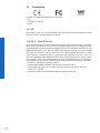
16.Conformity�������������������������������������������������������������������������������������������������������������� 52
16.1 CE����������������������������������������������������������������������������������������������������������������������� 52
16.2 FCC – Class B Device���������������������������������������������������������������������������������������� 52
3
1. General Information
Read these manual carefully and observe the notes and safety instructions!
Notice
This is the technical documentation for the Baumer HXC Series. The Baumer Camera
HXC 13 has it own technical documentation!
Thank you for purchase a camera of the Baumer family. This User´s Guide describes how
to connect, set up and use the camera.
Keep the User´s guide store in a safe place and transmit them to the eventually following
users. Please also note the provided technical data sheet.
Target group for this User´s Guide
This User's Guide is aimed at experienced business users, which want to integrate
camera(s) into a vision system.
Copyright
Any duplication or reprinting of this documentation, in whole or in part, and the reproduction of the illustrations even in modified form is permitted only with the written approval of
Baumer. This document is subject to change without notice.
Classification of the safety instructions
In the User´s Guide, the safety instructions are classified as follows:
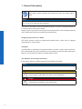
Notice
Gives helpful notes on operation or other general recommendations.
Pictogram
Pictogram
4
Caution
Indicates a possibly dangerous situation. If the situation is not avoided, slight
or minor injury could result or the device may be damaged.
Danger!
Indicates an immediate imminent danger. If the danger is not avoided, the
consequences are death or very serious injury.
2. General safety instructions
Observe the the following safety instructions when using the camera to avoid any damage
or injuries.
Danger!
Voltage on electronic components and power lines.
Voltage can be danderous.
The installation of electronic components only carried out by a qualified
electrician!
3. Intended Use
The camera is used to capture images that can be transferred over two CamerLink interfaces to a PC.
Notice
Use the camera only for its intended purpose! For any use that is not described in the
technical documentation poses dangers and will void the warranty. The risk has to be
borne solely by the unit´s owner.
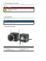
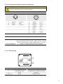
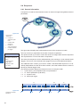
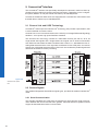
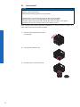
4. General Description
1
3
2
4
6
5
Nr.
Description
Nr.
Description
1
(respective) lens mount
4
Digial-IO supply
2
Power supply
5
CameraLink® Base socket
3
CameraLink® Full socket
6
Signaling-LED
5
5. Camera Models
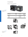
5.1 HXC – Cameras with C-Mount
Figure 1 ►
Front and rear view of
a Baumer HXC camera
with C-Mount
Camera Type
Sensor
Size
Resolution
Full
Frames
[max. fps]
HXC20
2/3"
2048x1088
337
HXC40
1"
2048x2048
180
HXC20c
2/3"
2048x1088
337
HXC40c
1"
2048x2048
180
Dimensions
36
37,4
6
36
26
52
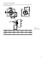
Figure 2 ►
Dimensions of a
Baumer HXC camera
with C-Mount.
36
36
26
52
16 x M3 depth 6
4 x M3 depth 6
26
36
UNC 1/4 20
5.2 HXC-F – Cameras with F-Mount
◄ Figure 3
Front view of a Baumer
HXC camera with FMount
Sensor
Size
Resolution
Full
Frames
[max. fps]
HXC20-F
2/3"
2048x1088
337
HXC40-F
1"
2048x2048
180
HXC20c-F
2/3"
2048x1088
337
HXC40c-F
1"
2048x2048
180
Camera Type
Dimensions
26
36
UNC 1/4 20
36
26
52
16 x M3 depth 6
37
36
26
52
◄ Figure 4
Dimensions of a
Baumer HXC-F
camera.
7
6. Product Specifications
6.1 Sensor Specifications
6.1.1 Quantum Efficiency for Baumer HXC Cameras
The quantum efficiency characteristics of monochrome (also in NIR) and color matrix sensors for Baumer HXC cameras are displayed in the following graphs. The characteristic
curves for the sensors do not take the characteristics of lenses and light sources without
filters into consideration, but are measured with an AR coated cover glass.
Figure 5 ►
Quantum efficiency for
Baumer HXC cameras.
Quantum Efficiency [%]
Quantum Efficiency [%]
Values relating to the respective technical data sheets of the sensors manufacturer.
NIR
350
450
550
650
HXC 20/40 (monochrome)
750
850
950
1050
Wave Length [nm]
350
450
550
650
HXC 20/40 (color)
750
850
950
1050
Wave Length [nm]
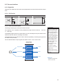
6.1.2 Shutter
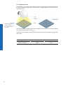
All cameras of the HXC series are equipped with a global shutter.
Figure 6 ►
Structure of an imaging sensor with global
shutter
Global shutter means that all pixels of the sensor are reset and afterwards exposed for a
specified interval (texposure).
For each pixel an adjacent storage circuit exists. Once the exposure time elapsed, the
information of a pixel is transferred immediately to its circuit and read out from there.
Due to the fact that photosensitive area gets "lost" by the implementation of the circuit
area, the pixels are equipped with microlenses, which focus the light on the pixel.
8
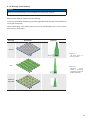
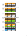
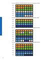
6.1.3 Digitization Taps
The CMOSIS sensors, employed in Baumer HXC cameras can be read out up to 16 channels in parallel.
Notice
More channels increase the speed (framerate), but more channels generate a higher
power.
Use only the maximum required number of channels!
Notice
Due to sensor characteristics in 12 bit mode only 2 or 4 channels are available.
Readout with 16 Channels
Readout with 4 Channels
Readout with 8 Channels
Readout with 2 Channels
◄ Figure 7
Digitization Tap of the
Baumer HXC Cameras
9
6.2 Timings
Notice
Overlapped mode can be switched off with setting the readout mode to sequential shutter instead of overlapped shutter.
The image acquisition consists of two seperate, successively processed components.
Exposing the pixels on the photosensitive surface of the sensor is only the first part of the
image acquisition. After completion of the first step, the pixels are read out.
The exposure time (texposure) can be adjusted by the user, however, the time needed for the
readout (treadout) is given by the particular sensor, image format and configuration.
Baumer HXC cameras can be operated with two modes, the Free Running Mode and the
Trigger Mode.
The cameras can be operated non-overlapped*) or overlapped. Depending on the mode
used, and the combination of exposure and readout time:
Non-overlapped Operation
Overlapped Operation
Here the time intervals are long enough
to process exposure and readout successively.
In this operation the exposure of a frame
(n+1) takes place during the readout of
frame (n).
Exposure
Exposure
Readout
Readout
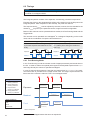
6.2.1 Free Running Mode
In the "Free Running" mode the camera records images permanently and sends them to
the PC. In order to achieve an optimal (with regard to the adjusted exposure time texposure
and image format) the camera is operated overlapped.
In case of exposure times equal to / less than the readout time (texposure ≤ treadout), the maximum frame rate is provided for the image format used. For longer exposure times the
frame rate of the camera is reduced. This is for overlapped mode.
Timings:
A - exposure time
frame (n) effective
B - image parameters frame (n) effective
C - exposure time
frame (n+1) effective
D - image parameters frame (n+1) effective
Exposure
texposure(n)
treadout(n)
Readout
Image parameters:
Offset
Gain
Mode
Partial Scan
tflash(n)
Flash
texposure(n+1)
tflash(n+1)
tflashdelay
tflash = texposure
10
*)
Non-overlapped means the same as sequential.
treadout(n+1)
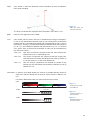
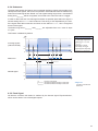
6.2.2 Trigger Mode
After a specified external event (trigger) has occurred, image acquisition is started. Depending on the interval of triggers used, the camera may operate non-overlapped or overlapped in this mode, when overlapped mode is enabled.
With regard to timings in the trigger mode, the following basic formulas need to be taken
into consideration:
Case
texposure < treadout
texposure > treadout
Formula
(1)
(2)
(3)
(4)
tearliestpossibletrigger(n+1) = treadout(n) - texposure(n+1)
tnotready(n+1) = texposure(n) + treadout(n) - texposure(n+1)
tearliestpossibletrigger(n+1) = texposure(n)
tnotready(n+1) = texposure(n)
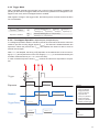
6.2.2.1 Overlapped Operation: texposure(n+2) = texposure(n+1)
In overlapped operation attention should be paid to the time interval where the camera is
unable to process occuring trigger signals (tnotready). This interval is situated between two
exposures. When this process time tnotready has elapsed, the camera is able to react to
external events again.
After tnotready has elapsed, the timing of (E) depends on the readout time of the current image (treadout(n)) and exposure time of the next image (texposure(n+1)). It can be determined by the
formulas mentioned above (no. 1 or 3, as is the case).
In case of identical exposure times, tnotready remains the same from acquisition to acquisition.
Trigger
tmin
ttriggerdelay
Exposure
texposure(n)
treadout(n)
Readout
TriggerReady
Flash
texposure(n+1)
treadout(n+1)
tnotready
tflash(n)
tflashdelay
tflash(n+1)
Timings:
A - exposure time
frame (n) effective
B - image parameters frame (n) effective
C - exposure time
frame (n+1) effective
D - image parameters frame (n+1) effective
E - earliest possible trigger
Image parameters:
Offset
Gain
Mode
Partial Scan
11
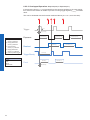
6.2.2.2 Overlapped Operation: texposure(n+2) > texposure(n+1)
If the exposure time (texposure) is increased form the current acquisition to the next acquisition, the time the camera is unable to process occuring trigger signals (tnotready) is scaled
down.
This can be simulated with the formulas mentioned above (no. 2 or 4, as is the case).
Trigger
tmin
ttriggerdelay
Timings:
A - exposure time
frame (n) effective
B - image parameters frame (n) effective
C - exposure time
frame (n+1) effective
D - image parameters frame (n+1) effective
E - earliest possible trigger
Image parameters:
Offset
Gain
Mode
Partial Scan
12
Exposure
texposure(n)
treadout(n)
Readout
TriggerReady
Flash
texposure(n+1)
treadout(n+1)
tnotready
tflash(n)
tflashdelay
texposure(n+2)
tflash(n+1)
6.2.2.3 Overlapped Operation: texposure(n+2) < texposure(n+1)
If the exposure time (texposure) is decreased from the current acquisition to the next acquisition, the time the camera is unable to process occuring trigger signals (tnotready) is scaled
up.
When decreasing the texposure such, that tnotready exceeds the pause between two incoming
trigger signals, the camera is unable to process this trigger and the acquisition of the image will not start (the trigger will be skipped).
Trigger
tmin
ttriggerdelay
Exposure
texposure(n)
treadout(n)
Readout
TriggerReady
Flash
texposure(n+1)
texposure(n+2
treadout(n+1)
tnotready
tflash(n)
tflash(n+1)
tflashdelay
Timings:
A - exposure time
frame (n) effective
B - image parameters frame (n) effective
C - exposure time
frame (n+1) effective
D - image parameters frame (n+1) effective
E - earliest possible trigger
F - frame not started /
trigger skipped
Image parameters:
Offset
Gain
Mode
Partial Scan
Notice
From a certain frequency of the trigger signal, skipping triggers is unavoidable. In general, this frequency depends on the combination of exposure and readout times and
shutter mode.
13
6.2.2.4 Non-overlapped Operation
If the period between two trigger pulses is long enough, so that the image acquisitions
(texposure + treadout) run successively, the camera operates non-overlapped. In the following
figure is the shutter mode set to overlapped.
Trigger
tmin
ttriggerdelay
Timings:
A - exposure time
frame (n) effective
B - image parameters frame (n) effective
C - exposure time
frame (n+1) effective
D - image parameters frame (n+1) effective
E - earliest possible trigger
Image parameters:
Offset
Gain
Mode
Partial Scan
14
Exposure
texposure(n)
treadout(n)
Readout
TriggerReady
Flash
texposure(n+1)
treadout(n+1)
tnotready
tflash(n)
tflashdelay
tflash(n+1)
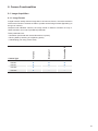
6.3 Field of View Position
The typical accuracy by assumption of the root mean square value is displayed in the
figures and the table below:
±ß
±YR
±YM
±XM
±X R
Photosensitive
surface of the
sensor
◄ Figure 8
Sensor accuracy of
Baumer HXC cameras.
±Z
Camera
Type
± xM,typ
[mm]
± yM,typ
[mm]
± xR,typ
[mm]
± yR,typ
[mm]
± βtyp
[°]
± ztyp
[mm]
HXC20
0,18
0,18
0,14
0,14
1,2
0,025
HXC40
0,18
0,18
0,14
0,14
1,2
0,025
15
6.4 Process- and Data Interface
6.4.1 Pin-Assignment CameraLink® Interface
Notice
CL
L FULL
Baumer
Type HXCXXx (xxxxxxx)
R1 0
S/N 000XXXXX
L BASE
BA
CL
The camera has two CameraLink sockets. To differentiate between CameraLink Base and CamerLink Full socket, please look at the label. You can
not use the CL Full socket alone!
Date / CameraLink® Full
1
GND
10
Z2-
19
Y3+
2
Y0-
11
ZCLK-
20
100 Ω Term.
3
Y1-
12
Z3-
21
Z0+
4
Y2-
13
GND
22
Z1+
5
YCLK-
14
GND
23
Z2+
6
Y3-
15
Y0+
24
ZCLK+
7
100 Ω Term.
16
Y1+
25
Z3+
8
Z0-
17
Y2+
26
GND
9
Z1-
18
YCLK+
CC2+
19
X3+
Data / Control / CameraLink® Base
16
1
GND
10
2
X0-
11
CC3-
20
SERTC-
3
X1-
12
CC4+
21
SERTFG+
4
X2-
13
GND
22
CC1+
5
XCLK-
14
GND
23
CC2-
6
X3-
15
X0+
24
CC3+
7
SERTC+
16
X1+
25
CC4-
8
SERTFG-
17
X2+
26
GND
9
CC1-
18
XCLK+
6.4.2 Pin-Assignment Power Supply and Digital IOs
Caution
A power supply with electrical isolation is required for proper operation of the
camera. Otherwise the device may be damaged.
M8 / 3 pins
M8 / 8 pins
6
3
1
(brown)
3
(blue)
4
(black)
4
7
3
1
4
1
5
8
2
Power VCC
1
(white)
Line 9
GND
2
(brown)
Line 1
not used
3
(green)
Line 0
4
(yellow)
GND
5
(grey)
6
(pink)
Uext
7
(blue)
Line 8
8
(red)
Line 2
Line 7
Power Supply
Power VCC
9,6 VDC ... 30 VDC
I
Mono8, CameraLink base, dual tap, 40 MHz; 190 mA .. 550 mA
Mono8, CameraLink full, 10 tap, 48 MHz; 200 mA .. 620 mA
Power consumption
approx. 5.5 Watt (with camera factory settings)
6.4.3 LED Signaling
1
2
LED
1
2
Signal
Meaning
green
Transmitting
red (yellow in both)
Configuration command processing
green
Power on
yellow
Readout active
17
6.5 Environmental Requirements
6.5.1 Temperature and Humidity Range*)
Temperature
Storage temperature
HXC20
-10°C ... +70°C ( +14°F ... +158°F)
HXC40
-10°C ... +70°C ( +14°F ... +158°F)
Operating temperature*
HXC20
+5°C ... +60°C (+41°F ... +140°F)
HXC40
Housing operating temperature
+5°C ... +60°C (+41°F ... +140°F)
**)***)
HXC20
max. +65°C (+149°F)
HXC40
max. +65°C (+149°F)
Internal operating temperature
HXC20
max. +60°C (+140°F)
HXC40
max. +60°C (+140°F)
Humidity
Storage and Operating Humidity
10% ... 90%
Non-condensing
Figure 10 ►
Temperature measurement points of Baumer
HXC cameras.
6.5.2 Heat Transmission
It is very important to provide adequate dissipation of heat, to ensure that the housing
temperature does not reach or exceed +65°C (+149°F). As there are numerous possibilities for installation, Baumer do not specifiy a specific method for proper heat dissipation,
but suggest the following principles:
▪▪ operate the cameras only in mounted condition
▪▪ mounting in combination with forced convection may provide proper heat dissipation
18
*)
**)
***)
Please refer to the respective data sheet.
Measured at temperature measurement point (T).
Housing temperature is limited by sensor specifications.
6.5.3 Mechanical Tests
Environmental
Testing
Standard
Parameter
Vibration, sinusodial
IEC 60068-2-6
Search for Resonance
10-2000 Hz
Amplitude underneath crossover
frequencies
1.5 mm
Acceleration
1g
Test duration
15 min
Frequency range
20-1000 Hz
Acceleration
10 g
Displacement
5.7 mm
Test duration
300 min
Puls time
11 ms / 6
ms
Acceleration
50 g / 100 g
Pulse Time
2 ms
Acceleration
80 g
Vibration,
broad band
Shock
Bump
IEC 600682-64
IEC 600682-27
IEC60068-229
19
7. Software
7.1 Baumer-GAPI
Baumer-GAPI stands for Baumer “Generic Application Programming Interface”. With this
API Baumer provides an interface for optimal integration and control of Baumer Gigabit
Ethernet (GigE) , Baumer CameraLink® and Baumer FireWire™ (IEEE1394) cameras.
This software interface allows changing to other camera models or interfaces. It also allows the simultaneous operation of Baumer cameras with Gigabit Ethernet, CameraLink®
and FireWire™ interfaces.
This GAPI supports Windows® (XP and Win7) and) operating systems in 32 bit, as well
as in 64 bit. It provides interfaces to several programming languages, such as C, C++
and the .NET™ Framework on Windows®, as well as Mono on Linux® operating systems,
which offers the use of other languages, such as e.g. C# or VB.NET.
To work with Baumer HXC Cameras you need the BGAPI V. 1.7.0 or newer.
Notice
There is currently no BGAPI version for Linux available with support for CameraLink®.
Notice
Please note the extra instructions to the software BGAPI. Specifically for CameraLink®
Cameras, the "User´s Guide CLConfig Tool".
20
8. Camera Functionalities
8.1 Image Acquisition
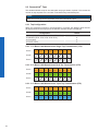
8.1.1 Image Format
A digital camera usually delivers image data in at least one format - the native resolution
of the sensor. Baumer cameras are able to provide several image formats (depending on
the type of camera).
Compared with standard cameras, the image format on Baumer cameras not only includes resolution, but a set of predefined parameter.
Camera Type
Full frame
Binning 2x1
Subsampling 2x2
These parameters are:
▪▪ Resolution (horizontal and vertical dimensions in pixels)
▪▪ Binning Mode (combining of neighboring pixels)
▪▪ Subsampling (not every pixel is read)
HXC20
■
■
■
HXC40
■
■
■
HXC20c
■
□
□
HXC40c
■
□
□
21
8.1.2 Pixel Format
On Baumer digital cameras the pixel format depends on the selected image format.
Mono 8
Mono 10
Mono 12
BayerRG8
BayerRG10
BayerRG12
8.1.2.1 Pixel Formats on Baumer HXC Cameras
HXC20
■
■
■
□
□
□
HXC40
■
■
■
□
□
□
HXC20c
□
□
□
■
■
■
HXC40c
□
□
□
■
■
■
Camera Type
Mono
Color
8.1.2.2 Definitions
Below is a general description of pixel formats. The table above shows, which camera
supports which format.
RAW:
Raw data format. Here the data are stored without processing.
Bayer:
Raw data format of color sensors.
Color filters are placed on these sensors in a checkerboard pattern, generally
in a 50% green, 25% red and 25% blue array.
Mono:
Monochrome. The color range of mono images consists of shades of a single
color. In general, shades of gray or black-and-white are synonyms for monochrome.
Figure 11 ►
Sensor with Bayer Pattern.
22
RGB:
Color model, in which all detectable colors are defined by three coordinates,
Red, Green and Blue.
◄ Figure 12
RBG color space displayed as color tube.
The three coordinates are displayed within the buffer in the order R, G, B.
BGR:
Here the color alignment mirrors RGB.
YUV:
Color model, which is used in the PAL TV standard and in image compression.
In YUV, a high bandwidth luminance signal (Y: luma information) is transmitted
together with two color difference signals with low bandwidth (U and V: chroma
information). Thereby U represents the difference between blue and luminance
(U = B - Y), V is the difference between red and luminance (V = R - Y). The third
color, green, does not need to be transmitted, its value can be calculated from
the other three values.
YUV 4:4:4
Here each of the three components has the same sample rate.
Therefore there is no subsampling here.
YUV 4:2:2
The chroma components are sampled at half the sample rate.
This reduces the necessary bandwidth to two-thirds (in relation to
4:4:4) and causes no, or low visual differences.
YUV 4:1:1
Here the chroma components are sampled at a quater of the
sample rate.This decreases the necessary bandwith by half (in
relation to 4:4:4).
Pixel depth: In general, pixel depth defines the number of possible different values for
each color channel. Mostly this will be 8 bit, which means 28 different "colors".
For RGB or BGR these 8 bits per channel equal 24 bits overall.
8 bit:
Byte 1
10 bit:
Byte 2
Byte 3
◄ Figure 13
Bit string of Mono 8 bit
and RGB 8 bit.
unused bits
Byte 1
12 bit:
Byte 2
unused bits
Byte 1
◄ Figure 14
Spreading of Mono 10
bit over 2 bytes.
◄ Figure 15
Spreading of Mono 12
bit over two bytes.
Byte 2
23
8.1.3 Exposure Time
On exposure of the sensor, the inclination of photons produces a charge separation on
the semiconductors of the pixels. This results in a voltage difference, which is used for
signal extraction.
Figure 16 ►
Incidence of light causes
charge separation on
the semiconductors of
the sensor.
The signal strength is influenced by the incoming amount of photons. It can be increased
by increasing the exposure time (texposure).
On Baumer HXC cameras, the exposure time can be set within the following ranges (step
size 1μsec):
Camera Type
HXC20 / HXC20c
HXC40 / HXC40c
24
texposure min
texposure max
4 μsec
1 sec
4 μsec
1 sec
8.1.4 Look-Up-Table
The Look-Up-Table (LUT) can only be used at monochrome cameras. It contains 212
(4096) values for the available levels of gray. These values can be adjusted by the user.
Notice
The LUT always calculates with 12 bit input and 12 bit output. In 8/10 bit mode, the lower
bits of the input values are equal zero but can be spread to full 12 bit because of digital
gain. Therefore, all values of the LUT have to be filled in.
H
8.1.5 Gamma Correction
With this feature, Baumer HXC cameras offer the possibility of compensating nonlinearity
in the perception of light by the human eye.
For this correction, the corrected pixel intensity (Y') is calculated from the original intensity
of the sensor's pixel (Yoriginal) and correction factor γ using the following formula (in oversimplified version):
γ
Y' = Yoriginal
8.1.6 Region of Interest (ROI)
0
E
▲ Figure 17
Non-linear perception of
the human eye.
H -Perception of bright-
ness
E - Energy of light
With this function it is possible to predefine a so-called Region of Interest (ROI) or Partial
Scan. The ROI is an area of pixels of the sensor. After image acquisition, only the information of these pixels is sent to the PC.
Therefore all the lines of the sensor need not be read out, which decreases the readout
time (treadout). This increases the frame rate.
This function is employed, when only a region of the field of view is of interest. It is coupled
to a reduction in resolution.
The ROI is specified by four values:
▪▪ Offset X
▪▪ Offset Y
▪▪ Size X
▪▪ Size Y
- x-coordinate of the first relevant pixel
- y-coordinate of the first relevant pixel
- horizontal size of the ROI
- vertical size of the ROI
Notice
The values of the Offset X and Size X must be a multible of 32!
The step size in Y direction is 1 pixel at monochrome cameras and 2 pixel at color cameras.
Start ROI
End ROI
◄ Figure 18
Parameters of the ROI.
25
8.1.7 ROI Readout
For the readout of the ROI, the horizontal subdivision of the sensor is unimportant – only
the vertical subdivision is of importance.
Start ROI
End ROI
Figure 19 ►
ROI: Readout
The readout is line based, which means always a complete line of pixels needs to be read
out and afterwards the irrelevant information is discarded.
End ROI
Start ROI
Figure 20 ►
ROI:
Discarded Information
26
8.1.8 Binning / Subsampling
Notice
Binning and Subsampling are only available at monochrome cameras.
Baumer HXC cameras support horizontal Binning.
In binning, horizontally neighboring pixels are aggregated and reported to the software as
one single "superpixel".
When subsampling, only certain pixels are read out. (Subsampling 2x2 = every second
pixel in every second line.)
Binning
Illustration
Example
without
◄ Figure 21
Full frame image, no
binning of pixels.
2x1
◄ Figure 22
Horizontal
binning
causes a horizontally
compressed image with
doubled brightness.
Subsampling 2x2
27
8.1.9 Brightness Correction (Binning Correction)
The summation of pixel values may cause an overload. To prevent this, binning correction
was introduced.
Binninig
2x1
Realization
2x1 binning takes place within the FPGA of the camera. The binning correction is realized by averaging the pixel values instead of simply adding
them.
8.2 Color Adjustment – White Balance
This feature is available on all color cameras of the Baumer HXC series.
White balance means independent adjustment of the three color channels, red,
green and blue by employing of a correction factor for each channel.
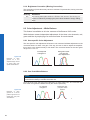
8.2.1 User-specific Color Adjustment
The user-specific color adjustment in Baumer color cameras facilitates adjustment of the
correction factors for each color gain. This way, the user is able to adjust the amplification of each color channel exactly to his needs. The correction factors for the color gains range from 1.0 to 4.0.
non-adjusted
histogramm
histogramm after
user-specific
color adjustment
Figure 23 ►
Examples of histogramms for a nonadjusted image and for
an image after userspecific white balance..
8.2.2 One Push White Balance
Notice
Due to the internal processing of the camera, One Push White Balance refers to the
current ROI but always considers the entire row.
Here, the three color spectrums are balanced to a single white point. The correction factors of the color gains are determined by the camera (one time).
non-adjusted
histogramm
Figure 24 ►
Examples of histogramms for a non-adjusted image and for an
image after "one push"
white balance.
28
histogramm after
„one push“ white
balance
8.3 Analog Controls
8.3.1 Offset / Black Level
On Baumer cameras, the offset (or black level) is adjustable from 0 to 255 LSB (always
related to 12 bit).
8.3.2 Gain digital
In industrial environments motion blur is unacceptable. Due to this fact exposure times
are limited. However, this causes low output signals from the camera and results in dark
images. To solve this issue, the signals can be amplified by a user-defined gain factor
within the camera. This gain factor is adjustable from 1.0 to 4.0.
Notice
Increasing the gain factor causes an increase of image noise and leads to missing
codes at Mono12, if the gain factor > 1.0
29
8.4 Sequencer
8.4.1 General Information
A sequencer is used for the automated control of series of images using different sets of
parameters.
n0
n1
A
m
B
Figure 25 ►
Flow chart of
sequencer.
m - number of sequence repeti-
tions
n - number of set
repetitions
o - number of
sets of parameters
z - number of frames
per trigger
Sequencer Parameter:
The mentioned sets of
parameter include the following:
▪▪ Exposure time
▪▪ Gain factor
▪▪ Repeat counter
▪▪ IO-Value
o
n2
C
z
nx-1
The figure above displays the fundamental structure of the sequencer module.
The loop counter (m) represents the number of sequence repetitions.
The repeat counter (n) is used to control the amount of images taken with the respective
sets of parameters. For each set there is a separate n.
The start of the sequencer can be realized directly (free running) or via an external event
(trigger). The source of the external event (trigger source) must be determined before.
The additional frame counter (z) is used to create a half-automated sequencer. It is absolutely independent from the other three counters, and used to determine the number of
frames per external trigger event.
The following timeline displays the temporal course of a sequence with:
▪▪ n = (A=5), (B=3), (C=2) repetitions per set of parameters
▪▪ o = 3 sets of parameters (A,B and C)
▪▪ m = 1 sequence and
▪▪ z = 2 frames per trigger
A
n=1
Figure 26 ►
Timeline for a single
sequence
30
n=2
z=2
B
n=3
n=4
z=2
n=5
n=1
z=2
n=2
C
n=3
z=2
n=1
n=2
z=2
t
8.4.2 Examples
8.4.2.1 Sequencer without Machine Cycle
C
C
Sequencer
Start
B
B
A
◄ Figure 27
Example for a fully automated sequencer.
A
The figure above shows an example for a fully automated sequencer with three sets of
parameters (A,B and C). Here the repeat counter (n) is set for (A=5), (B=3), (C=2) and the
loop counter (m) has a value of 2.
When the sequencer is started, with or without an external event, the camera will record
the pictures using the sets of parameters A, B and C (which constitutes a sequence).
After that, the sequence is started once again, followed by a stop of the sequencer - in this
case the parameters are maintained.
8.4.2.2 Sequencer Controlled by Machine Steps (trigger)
C
C
Sequencer
Start
B
B
A
A
Trigger
◄ Figure 28
Example for a half-automated sequencer.
The figure above shows an example for a half-automated sequencer with three sets of
parameters (A,B and C) from the previous example. The frame counter (z) is set to 2. This
means the camera records two pictures after an incoming trigger signal.
8.4.3 Capability Characteristics of Baumer-GAPI Sequencer Module
▪▪ up to 128 sets of parameters
▪▪ up to 4 billion loop passes
▪▪ up to 4 billion repetitions of sets of parameters
▪▪ up to 4 billion images per trigger event
▪▪ free running mode without initial trigger
31
8.4.4 Double Shutter
This feature offers the possibility of capturing two images in a very short interval. Depending on the application, this is performed in conjunction with a flash unit. Thereby the first
exposure time (texposure) is arbitrary and accompanied by the first flash. The second exposure time must be equal to, or longer than the readout time (treadout) of the sensor. Thus the
pixels of the sensor are recepitve again shortly after the first exposure. In order to realize
the second short exposure time without an overrun of the sensor, a second short flash
must be employed, and any subsequent extraneous light prevented.
Trigger
Flash
Exposure
Prevent Light
Figure 29 ►
Example of a double
shutter.
Readout
On Baumer TXG cameras this feature is realized within the sequencer.
In order to generate this sequence, the sequencer must be configured as follows:
Parameter
32
Setting:
Sequencer Run Mode
Once by Trigger
Sets of parameters (o)
2
Loops (m)
1
Repeats (n)
1
Frames Per Trigger (z)
2
8.5 Process Interface
8.5.1 Digital IOs
Cameras of the Baumer HXC series are equipped with three input lines and three output
lines.
8.5.1.1 IO Circuits
Output high active
Camera
Output low active
Customer Device
Camera
Customer Device
IO Power VCC
IO Power VCC
Input
Customer Device
Camera
DRV
RL
IOUT
RL
IOUT
IO GND
IO GND
IO GND
8.5.1.2 User Definable Inputs
The wiring of these input connectors is left to the user.
An exception is the compliance with predetermined high and low levels (0 .. 4.5V low,
11 .. 30V high).
The defined signals will have no direct effect, but can be analyzed and processed on the
software side and used for controlling the camera.
The employment of a so called "IO matrix" offers the possibility of selecting the signal and
the state to be processed.
On the software side the input signals are named "Line0", "Line1" and "Line2".
state selection
(software side)
▪▪ No need for a perfect
state high
Line0
(Input) Line0
alignment of an external
trigger sensor
state low
▪▪ Different objects can be
state high
(Input) Line1
Trigger Delay:
The trigger delay is a
flexible user-defined delay
between the given trigger
impulse and the image capture. The delay time can
be set between 0.0 μsec
and 2.0 sec with a stepsize
of 1 μsec. In the case of
multiple triggers during the
delay the triggers will be
stored and delayed, too.
The buffer is able to store
up to 512 trigger
signals during the delay.
Your benefits:
Line1
captured without hardware
changes
state low
state high
(Input) Line2
Line2
state low
IO Matrix
◄ Figure 30
IO matrix of the Baumer
HXC on input side.
33
8.5.1.3 Configurable Outputs
With this feature, Baumer offers the possibility of wiring the output connectors to internal
signals, which are controlled on the software side.
Hereby on cameras of the HXC series, 21 signal sources – subdivided into three categories – can be applied to the output connectors.
The first category of output signals represents a loop through of signals on the input side,
such as:
Signal Name
Explanation
Line0
Signal of input "Line0" is loopthroughed to this ouput
Line1
Signal of input "Line1" is loopthroughed to this ouput
Line2
Signal of input "Line2" iys loopthroughed to this ouput
FrameGrabberLine0
Signal of input "FrameGrabberLine0" is loopthroughed to
this ouput
FrameGrabberLine1
Signal of input "FrameGrabberLine1" is loopthroughed to
this ouput
FrameGrabberLine2
Signal of input "FrameGrabberLine2" is loopthroughed to
this ouput
FrameGrabberLine3
Signal of input "FrameGrabberLine3" is loopthroughed to
this ouput
Within the second category you will find signals that are created on camera side:
Signal Name
Explanation
FrameActive
The camera processes a Frame consisting of exposure
and readout
TriggerReady
Camera is able to process an incoming trigger signal
TriggerOverlapped
The camera operates in overlapped mode
TriggerSkipped
Camera rejected an incoming trigger signal
ExposureActive
Sensor exposure in progress
TransferActive
Image transfer via hardware interface in progress
state low
state high
(Output) Line 8
state low
state high
(Output) Line 9
Figure 31 ►
IO matrix of the Baumer
HXC on output side.
34
state low
IO Matrix
FrameActive
TriggerReady
TriggerOverlapped
TriggerSkipped
ExposureActive
TransferActive
nternal Signals
state high
(Output) Line 7
signal selection
(software side)
UserOutput0
UserOutput1
UserOutput2
Timer1Active
SequencerOutput0
SequencerOutput1
SequencerOutput2
User defined Signals
state selection
(software side)
Off
Line0
Line1
Line2
FrameGrabberLine0
FrameGrabberLine1
FrameGrabberLine2
FrameGrabberLine3
Loopthroughed Signals
Beside the 13 signals mentioned above, each output can be wired to a user-defined
signal ("UserOutput0", "UserOutput1", "UserOutput2", "SequenzerOut 0...2", "SW-Trigger", "Exposure Start", "Exposure End", "Frame Start", "Frame End") or disabled
("OFF").
8.5.2 Trigger Input / Trigger Delay
U
Trigger signals are used to synchronize the camera exposure and a machine cycle or, in
case of a software trigger, to take images at predefined time intervals. Different trigger
sources can be used:
30V
Line0
FrameGrabberLine1
11V
Line1
FrameGrabberLine2
4.5V
Line2
FrameGrabberLine3
FrameGrabberLine0
SW-Trigger
0
There are three types of modes. The timing diagrams for the three types you can see
below.
high
low
t
Figure 32 ▲
Trigger signal, valid for
Baumer cameras.
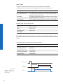
Normal Trigger with adjusted Exposure
Trigger (valid)
A
Camera in trigger
mode:
A - Trigger delay
B - Exposure time
C - Readout time
Exposure
B
Readout
C
Time
Pulse Width controlled Exposure
Trigger (valid)
Exposure
B
Readout
C
Time
Edge controlled Exposure
Trigger (valid)
Exposure
B
Readout
C
Time
35
able
logic
others
c
on
trol er
lectric se
m
pho
t
or
ns
oe
program
8.5.3 Trigger Source
Ha
a
rdw
re trigger
ger signal
trig
s
er
re trigg
twa
of
Figure 33 ►
Examples of possible
trigger sources.
Each trigger source has to be activated separately. When the trigger mode is activated,
the hardware trigger is activated by default.
36
8.5.4 Debouncer
The basic idea behind this feature was to seperate interfering signals (short peaks) from
valid square wave signals, which can be important in industrial environments. Debouncing
means that invalid signals are filtered out, and signals lasting longer than a user-defined
testing time tDebounceHigh will be recognized, and routed to the camera to induce a trigger.
In order to detect the end of a valid signal and filter out possible jitters within the signal, a
second testing time tDebounceLow was introduced. This timing is also adjustable by the user.
If the signal value falls to state low and does not rise within tDebounceLow , this is recognized
as end of the signal.
The debouncing times tDebounceHigh and tDebounceLow are adjustable from 0 to 5 msec in steps
of 1 μsec.
This feature is disabled by default.
Debouncer:
U
Please note that the edges
of valid trigger signals are
shifted by tDebounceHigh and
tDebounceLow!
Depending on these
two timings, the trigger
signal might be temporally
stretched or compressed.
30V
Incoming signals
(valid and invalid)
high
11V
4.5V
0
low
∆t1
∆t2
∆t3
∆t4
∆t5
t
∆t6
Debouncer
tDebounceHigh
U
t
tDebounceLow
30V
Filtered signal
11V
4.5V
high
low
0
t
∆tx
high time of the signal
tDebounceHigh user defined debouncer delay for state high
tDebounceLow user defined debouncer delay for state low
◄ Figure 34
Principle of the Baumer
debouncer.
8.5.5 Flash Signal
On Baumer cameras, this feature is realized by the internal signal "ExposureActive",
which can be wired to one of the digital outputs.
37
8.5.6 Timer
Timers were introduced for advanced control of internal camera signals.
On Baumer HXC cameras the timer configuration includes four components:
Setting
Description
TimerTriggerSource
This feature provides a source selection for each timer.
TimerTriggerActivation
This feature selects that part of the trigger signal (edges or
states) that activates the timer.
TimerDelay
This feature represents the interval between incoming trigger
signal and the start of the timer.
TimerDuration
By this feature the activation time of the timer is adjustable.
Different Timer sources can be used:
Line0
Exposure Start
Line1
Exposure End
Line2
Frame Start
TriggerSkipped
Frame End
SW-Trigger
For example the using of a timer allows you to control the flash signal in that way, that the
illumination does not start synchronized to the sensor exposure but a predefined interval
earlier.
For this example you must set the following conditions:
Setting
Value
TriggerSource
InputLine0
TimerTriggerSource
InputLine0
Outputline7 (Source)
Timer1Active
TimerTriggerActivation
Falling Edge
Trigger Polarity
Falling Edge
InputLine0
Exposure
Figure 35 ►
Possible Timer configuration on a Baumer
HXC canera.
38
Timer
ttriggerdelay
texposure
tTimerDelay
tTimerDuration
8.6 User Sets
Three user sets (1-3) are available for the Baumer cameras of the HXC series. The user
sets can contain the following information:
Parameter
Parameter
Binning Mode
Mirroring Control
CameraLink Control
Offset
Defectpixellist
Partial Scan
Digital I/O Settings
Pixelformat
Exposure Time
Readout Mode/Digitization Taps
Gain Factor
Testpattern
Look-Up-Table
Trigger Settings
Shutter Mode
Fixed Frame rate
Color Gains
Gamma
Speed Mode
IO-Settings
®
These user sets are stored within the camera and and cannot be saved outside the device.
By employing a so-called "user set default selector", one of the three possible user sets
can be selected as default, which means, the camera starts up with these adjusted parameters.
8.7 Factory Settings
The factory settings are stored in an additional parametrization set which is used by default. This settings are not editable.
39
9. CameraLink® Interface
The CameraLink® interface was specifically developed for cameras in machine vision applications and provides high transfer rates and low latency. Depending on the configuration (Base, Medium or Full) the transfer rate adds up to 800 MBytes/sec.
Cameras of the Baumer HXC series are equipped with a CameraLink® Full interface and
therewith able to transmit up to 800 MBytes/sec.
9.1 Channel Link and LVDS Technology
CameraLink® bases upon the Channel Link® technology, but provides a specification, that
is more beneficial for machine vision.
Channel Link® in turn is an advancement of the LDVS (Low Voltage Differential Signaling)
standard – a low power, high speed interface standard.
The Channel Link® technology consists of a transmitter receiver pair with 21, 28 or 48
single-ended data signals and a single-ended clock signal can be wired on transmitter
side. Within the transmitter the data is serialized with a ratio of 7:1. Afterwards the four resulting data streams and the clock signal are transferred via five LVDS pairs. On receiver
side the four LVDS data streams and the LVDS clock are reordered to parallel signals and
afterwards forwarded to further processing.
Figure 36 ►
Channel Link® operation.
9.2 Camera Signals
The standard designates three different signal types, provided via standard CameraLink®
cable:
9.2.1 Serial Communication
The standard regulates two LVDS pairs are allocated for asynchronous serial communication between the camera and the frame grabber. Cameras and frame grabbers should
support at least 9600 baud serial communication.
40
The following signals are designated:
Signal
Description
SerTFG
LVDS pair for serial communications to the frame grabber
SerTC
LVDS pair for serial communications to the camera
The serial interface must apply the following regulations:
▪▪ one start bit,
▪▪ one stop bit,
▪▪ no parity and
▪▪ no handshaking.
9.2.2 Camera Control
According to the CameraLink® standard four LVDS pairs have to be reserved for generalpurpose camera control. They are defined as frame grabber outputs and camera inputs.
The definition of these signals is left to the camera manufacturer.
Signal
Baumer Naming
Employment
Camera Control 1 (CC1) FrameGrabberLine0
Camera Control 2 (CC2) FrameGrabberLine1
Camera Control 3 (CC3) FrameGrabberLine2
On Baumer HXC cameras, the wiring
of these signals is arbitrary.
Camera Control 4 (CC4) FrameGrabberLine3
9.2.3 Video Data
The standard designates four signals (as well as the signal state) for the validation of
transmitted image data:
Signal
Description
FVAL
Frame Valid is defined high for valid lines.
LVAL
Line Valid is defined high for valid pixels.
DVAL
Data Valid is defined high for valid data.
Spare
Has been defined for future use.
41
9.3 CameraLink® Taps
The standard defines a tap as "the data path carrying a stream of pixels". This means the
number of taps equates to the number of simultaneously transferred pixel.
Notice
Please do not mix up sensor digitization taps and CameraLink® taps!
9.3.1 Tap Configuration
Within the subsequent sections, the transmission of images with different pixel formats
(bit depth) linked to the employment of different numbers of taps is displayed.
Configuration
Cables
CL Base (1T8, 2T8, 3T8, 1T10, 2T10, 1T12, 2T12)
1
CL Medium (3T10, 3T12, 4T8, 4T10 4T12)
2
CL Full (8T8)
2
CL Deca (10T8)
2
9.3.1.1 CL Base 8-bit Monochrome Single Tap Transmission (1T8)
Port A
Tap 1
Tap 1
Tap 1
Tap 1
Tap 1
Tap 1
Tap 1
Tap 1
bit 0
bit 1
bit 2
bit 3
bit 4
bit 5
bit 6
bit 7
Port B
Port C
9.3.1.2 CL Base 8-bit Monochrome Dual Tap Transmission (2T8)
Port A
Port B
Tap 1
Tap 1
Tap 1
Tap 1
Tap 1
Tap 1
Tap 1
Tap 1
bit 0
bit 1
bit 2
bit 3
bit 4
bit 5
bit 6
bit 7
Tap 2
Tap 2
Tap 2
Tap 2
Tap 2
Tap 2
Tap 2
Tap 2
bit 0
bit 1
bit 2
bit 3
bit 4
bit 5
bit 6
bit 7
Port C
9.3.1.3 CL Base 8-bit Monochrome Triple Tap Transmission (3T8)
Port A
Port B
Port C
42
Tap 1
Tap 1
Tap 1
Tap 1
Tap 1
Tap 1
Tap 1
Tap 1
bit 0
bit 1
bit 2
bit 3
bit 4
bit 5
bit 6
bit 7
Tap 2
Tap 2
Tap 2
Tap 2
Tap 2
Tap 2
Tap 2
Tap 2
bit 0
bit 1
bit 2
bit 3
bit 4
bit 5
bit 6
bit 7
Tap 3
Tap 3
Tap 3
Tap 3
Tap 3
Tap 3
Tap 3
Tap 3
bit 0
bit 1
bit 2
bit 3
bit 4
bit 5
bit 6
bit 7
9.3.1.4 CL Base 10-bit Monochrome Single Tap Transmission (1T10)
Port A
Port B
Tap 1
Tap 1
Tap 1
Tap 1
Tap 1
Tap 1
Tap 1
Tap 1
bit 0
bit 1
bit 2
bit 3
bit 4
bit 5
bit 6
bit 7
Tap 1
Tap 1
bit 8
bit 9
Port C
9.3.1.5 CL Base 10-bit Monochrome Dual Tap Transmission (2T10)
Port A
Port B
Port C
Tap 1
Tap 1
Tap 1
Tap 1
Tap 1
Tap 1
Tap 1
Tap 1
bit 0
bit 1
bit 2
bit 3
bit 4
bit 5
bit 6
bit 7
Tap 1
Tap 1
Tap 2
Tap 2
bit 8
bit 9
bit 8
bit 9
Tap 2
Tap 2
Tap 2
Tap 2
Tap 2
Tap 2
Tap 2
Tap 2
bit 0
bit 1
bit 2
bit 3
bit 4
bit 5
bit 6
bit 7
9.3.1.6 CL Base 12-bit Monochrome Single Tap Transmission (1T12)
Port A
Port B
Tap 1
Tap 1
Tap 1
Tap 1
Tap 1
Tap 1
Tap 1
Tap 1
bit 0
bit 1
bit 2
bit 3
bit 4
bit 5
bit 6
bit 7
Tap 1
Tap 1
Tap 1
Tap 1
bit 8
bit 9
bit 10
bit 11
Port C
9.3.1.7 CL Base 12-bit Monochrome Dual Tap Transmission (2T12)
Port A
Port B
Port C
Tap 1
Tap 1
Tap 1
Tap 1
Tap 1
Tap 1
Tap 1
Tap 1
bit 0
bit 1
bit 2
bit 3
bit 4
bit 5
bit 6
bit 7
Tap 1
Tap 1
Tap 1
Tap 1
Tap 2
Tap 2
Tap 2
Tap 2
bit 8
bit 9
bit 10
bit 11
bit 8
bit 9
bit 10
bit 11
Tap 2
Tap 2
Tap 2
Tap 2
Tap 2
Tap 2
Tap 2
Tap 2
bit 0
bit 1
bit 2
bit 3
bit 4
bit 5
bit 6
bit 7
9.3.1.8 CL Medium 10-bit Monochrome Triple Tap Transmission (3T10)
Port A
Port B
Port C
Tap 1
Tap 1
Tap 1
Tap 1
Tap 1
Tap 1
Tap 1
Tap 1
bit 0
bit 1
bit 2
bit 3
bit 4
bit 5
bit 6
bit 7
Tap 1
Tap 1
Tap 1
Tap 1
bit 8
bit 9
bit 8
bit 9
Tap 2
Tap 2
Tap 2
Tap 2
Tap 2
Tap 2
Tap 2
Tap 2
bit 0
bit 1
bit 2
bit 3
bit 4
bit 5
bit 6
bit 7
Tap 3
Tap 3
Tap 3
Tap 3
Tap 3
Tap 3
Tap 3
Tap 3
bit 2
bit 3
bit 4
bit 5
bit 6
bit 7
Port D
Port E
Port F
bit 0
bit 1
Tap 3
Tap 3
bit 8
bit 9
43
9.3.1.9 CL Medium 12-bit Monochrome Triple Tap Transmission (3T12)
Port A
Port B
Port C
Tap 1
Tap 1
Tap 1
Tap 1
Tap 1
Tap 1
Tap 1
Tap 1
bit 0
bit 1
bit 2
bit 3
bit 4
bit 5
bit 6
bit 7
Tap 1
Tap 1
Tap 1
Tap 1
Tap 2
Tap 2
Tap 2
Tap 2
bit 0
bit 1
bit 2
bit 3
bit 8
bit 9
bit 10
bit 11
Tap 2
Tap 2
Tap 2
Tap 2
Tap 2
Tap 2
Tap 2
Tap 2
bit 0
bit 1
bit 2
bit 3
bit 4
bit 5
bit 6
bit 7
Tap 3
Tap 3
Tap 3
Tap 3
Tap 3
Tap 3
Tap 3
Tap 3
bit 0
bit 1
bit 2
bit 3
bit 4
bit 5
bit 6
bit 7
Tap 3
Tap 3
Tap 3
Tap 3
bit 0
bit 1
bit 2
bit 3
Port D
Port E
Port F
9.3.1.10 CL Medium 8-bit Monochrome Quad Tap Transmission (4T8)
Port A
Port B
Port C
Port D
Tap 1
Tap 1
Tap 1
Tap 1
Tap 1
Tap 1
Tap 1
Tap 1
bit 0
bit 1
bit 2
bit 3
bit 4
bit 5
bit 6
bit 7
Tap 2
Tap 2
Tap 2
Tap 2
Tap 2
Tap 2
Tap 2
Tap 2
bit 0
bit 1
bit 2
bit 3
bit 4
bit 5
bit 6
bit 7
Tap 3
Tap 3
Tap 3
Tap 3
Tap 3
Tap 3
Tap 3
Tap 3
bit 0
bit 1
bit 2
bit 3
bit 4
bit 5
bit 6
bit 7
Tap 4
Tap 4
Tap 4
Tap 4
Tap 4
Tap 4
Tap 4
Tap 4
bit 0
bit 1
bit 2
bit 3
bit 4
bit 5
bit 6
bit 7
9.3.1.11 CL Medium 10-bit Monochrome Quad Tap Transmission (4T10)
Port A
Port B
Port C
Port D
Port E
Port F
Tap 1
Tap 1
Tap 1
Tap 1
Tap 1
Tap 1
Tap 1
Tap 1
bit 0
bit 1
bit 2
bit 3
bit 4
bit 5
bit 6
bit 7
Tap 1
Tap 1
Tap 2
Tap 2
bit 8
bit 9
bit 8
bit 9
Tap 2
Tap 2
Tap 2
Tap 2
Tap 2
Tap 2
Tap 2
Tap 2
bit 0
bit 1
bit 2
bit 3
bit 4
bit 5
bit 6
bit 7
Tap 4
Tap 4
Tap 4
Tap 4
Tap 4
Tap 4
Tap 4
Tap 4
bit 0
bit 1
bit 2
bit 3
bit 4
bit 5
bit 6
bit 7
Tap 3
Tap 3
Tap 3
Tap 3
Tap 3
Tap 3
Tap 3
Tap 3
bit 0
bit 1
bit 2
bit 3
bit 4
bit 5
bit 6
bit 7
Tap 3
Tap 3
Tap 4
Tap 4
bit 8
bit 9
bit 8
bit 9
9.3.1.12 CL Medium 12-bit Monochrome Quad Tap Transmission (4T12)
Port A
Port B
Port C
Port D
Port E
Port F
44
Tap 1
Tap 1
Tap 1
Tap 1
Tap 1
Tap 1
Tap 1
Tap 1
bit 0
bit 1
bit 2
bit 3
bit 4
bit 5
bit 6
bit 7
Tap 1
Tap 1
Tap 1
Tap 1
Tap 2
Tap 2
Tap 2
Tap 2
bit 8
bit 9
bit 10
bit 11
bit 8
bit 9
bit 10
bit 11
Tap 2
Tap 2
Tap 2
Tap 2
Tap 2
Tap 2
Tap 2
Tap 2
bit 0
bit 1
bit 2
bit 3
bit 4
bit 5
bit 6
bit 7
Tap 4
Tap 4
Tap 4
Tap 4
Tap 4
Tap 4
Tap 4
Tap 4
bit 0
bit 1
bit 2
bit 3
bit 4
bit 5
bit 6
bit 7
Tap 3
Tap 3
Tap 3
Tap 3
Tap 3
Tap 3
Tap 3
Tap 3
bit 0
bit 1
bit 2
bit 3
bit 4
bit 5
bit 6
bit 7
Tap 3
Tap 3
Tap 3
Tap 3
Tap 4
Tap 4
Tap 4
Tap 4
bit 8
bit 9
bit 10
bit 11
bit 8
bit 9
bit 10
bit 11
9.3.1.13 CL Full 8-bit Monochrome Eight Tap Transmission (8T8)
Port A
Port B
Port C
Port D
Port E
Port F
Port G
Port H
Tap 1
Tap 1
Tap 1
Tap 1
Tap 1
Tap 1
Tap 1
Tap 1
bit 0
bit 1
bit 2
bit 3
bit 4
bit 5
bit 6
bit 7
Tap 2
Tap 2
Tap 2
Tap 2
Tap 2
Tap 2
Tap 2
Tap 2
bit 0
bit 1
bit 2
bit 3
bit 4
bit 5
bit 6
bit 7
Tap 3
Tap 3
Tap 3
Tap 3
Tap 3
Tap 3
Tap 3
Tap 3
bit 0
bit 1
bit 2
bit 3
bit 4
bit 5
bit 6
bit 7
Tap 4
Tap 4
Tap 4
Tap 4
Tap 4
Tap 4
Tap 4
Tap 4
bit 0
bit 1
bit 2
bit 3
bit 4
bit 5
bit 6
bit 7
Tap 5
Tap 5
Tap 5
Tap 5
Tap 5
Tap 5
Tap 5
Tap 5
bit 0
bit 1
bit 2
bit 3
bit 4
bit 5
bit 6
bit 7
Tap 6
Tap 6
Tap 6
Tap 6
Tap 6
Tap 6
Tap 6
Tap 6
bit 0
bit 1
bit 2
bit 3
bit 4
bit 5
bit 6
bit 7
Tap 7
Tap 7
Tap 7
Tap 7
Tap 7
Tap 7
Tap 7
Tap 7
bit 0
bit 1
bit 2
bit 3
bit 4
bit 5
bit 6
bit 7
Tap 8
Tap 8
Tap 8
Tap 8
Tap 8
Tap 8
Tap 8
Tap 8
bit 0
bit 1
bit 2
bit 3
bit 4
bit 5
bit 6
bit 7
9.3.1.14 CL Deca 8-bit Monochrome Ten Tap Transmission (10T8)
Port A
Port B
Port C
Port D
Port E
Port F
Port G
Port H
Port I
Port J
Tap 1
Tap 1
Tap 1
Tap 1
Tap 1
Tap 1
Tap 1
Tap 1
bit 0
bit 1
bit 2
bit 3
bit 4
bit 5
bit 6
bit 7
Tap 2
Tap 2
Tap 2
Tap 2
Tap 2
Tap 2
Tap 2
Tap 2
bit 0
bit 1
bit 2
bit 3
bit 4
bit 5
bit 6
bit 7
Tap 3
Tap 3
Tap 3
Tap 3
Tap 3
Tap 3
Tap 3
Tap 3
bit 0
bit 1
bit 2
bit 3
bit 4
bit 5
bit 6
bit 7
Tap 4
Tap 4
Tap 4
Tap 4
Tap 4
Tap 4
Tap 4
Tap 4
bit 0
bit 1
bit 2
bit 3
bit 4
bit 5
bit 6
bit 7
Tap 5
Tap 5
Tap 5
Tap 5
Tap 5
Tap 5
Tap 5
Tap 5
bit 0
bit 1
bit 2
bit 3
bit 4
bit 5
bit 6
bit 7
Tap 6
Tap 6
Tap 6
Tap 6
Tap 6
Tap 6
Tap 6
Tap 6
bit 0
bit 1
bit 2
bit 3
bit 4
bit 5
bit 6
bit 7
Tap 7
Tap 7
Tap 7
Tap 7
Tap 7
Tap 7
Tap 7
Tap 7
bit 0
bit 1
bit 2
bit 3
bit 4
bit 5
bit 6
bit 7
Tap 8
Tap 8
Tap 8
Tap 8
Tap 8
Tap 8
Tap 8
Tap 8
bit 0
bit 1
bit 2
bit 3
bit 4
bit 5
bit 6
bit 7
Tap 7
Tap 7
Tap 7
Tap 7
Tap 7
Tap 7
Tap 7
Tap 7
bit 0
bit 1
bit 2
bit 3
bit 4
bit 5
bit 6
bit 7
Tap 8
Tap 8
Tap 8
Tap 8
Tap 8
Tap 8
Tap 8
Tap 8
bit 0
bit 1
bit 2
bit 3
bit 4
bit 5
bit 6
bit 7
45
9.3.2 Tap Geometry
Since frame grabbers possess the ability of image reconstruction from multi-tap cameras
"on-the-fly", the CameraLink® standards demands the specification of the used / supported tap geometries from the manufacturers of both, cameras and frame grabbers.
9.3.2.1 Single Tap Geometry
For single tap transmission the cameras of the Baumer HXC series employ the 1X-1Y tap
geometry:
Figure 37 ►
Tap geometry 1X-1Y.
The pixel information
is transmitted pixel-bypixel and line-by-line.
9.3.2.2 Dual Tap Geometry
For dual tap transmission the cameras of the Baumer HXC series employ the 1X2-1Y tap
geometry:
Figure 38 ►
Tap geometry 1X2-1Y.
9.3.2.3 Triple Tap Geometry
For triple tap transmission the cameras of the Baumer HXC series employ the 1X3-1Y tap
geometry:
Figure 39 ►
Tap geometry 1X3-1Y.
46
9.3.2.4 Quad, Eight and Ten Tap Geometry
For Quad, Eight and Ten tap transmission the cameras of the Baumer HXC series use the
same system.
◄ Figure 40
Tap geometry 1X4...101Y.
47
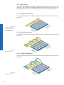
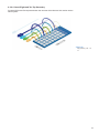
10. Lens install
Notice
Avoid contamination of the sensor and the lens by dust and airborne particles when
mounting a lens to the device!
Therefore the following points are very important:
▪▪ Install lenses in an environment that is as dust free as possible!
▪▪ Keep the dust covers on camera and lens as long as possible!
▪▪ Hold the camera downwards with unprotected sensor (or filter- /cover glass)!
▪▪ Avoid contact with any optical surface of the camera or lens!
At the example on the figures below the installation of C-mount objective is shown. At a
camera with F-Mount it is principle the same.
1. Turn the camera with the lens mount
to the bottom.
2. Unscrew the protective cap.
3. Screw the lens on the lens mount.
48
11. Cleaning
Cover glass
Notice
The sensor is mounted dust-proof. Remove of the cover glass for cleaning is not necessary.
Avoid cleaning the cover glass of the CCD sensor if possible. To prevent dust, follow the
instructions under "Install lens".
If you must clean it, use compressed air or a soft, lint free cloth dampened with a small
quantity of pure alcohol.
Housing
Caution!
volatile
solvents
Volatile solvents for cleaning.
Volatile solvents damage the surface of the camera.
Never use volatile solvents (benzine, thinner) for cleaning!
To clean the surface of the camera housing, use a soft, dry cloth. To remove persistent
stains, use a soft cloth dampened with a small quantity of neutral detergent, then wipe
dry.
12. Transport / Storage
Notice
Transport the camera only in the original packaging. When the camera is not installed,
then storage the camera in original packaging.
Storage Environment
Storage temperature
Storage Humidy
-10°C ... +70°C ( +14°F ... +158°F)
10% ... 90% non condensing
49
13. Disposal
Dispose of outdated products with electrical or electronic circuits, not in the
normal domestic waste, but rather according to your national law and the
directives 2002/96/EC and 2006/66/EC for recycling within the competent
collectors.
Through the proper disposal of obsolete equipment will help to save valuable resources and prevent possible adverse effects on human health and
the environment.
The return of the packaging to the material cycle helps conserve raw materials an reduces the production of waste. When no longer required, dispose
of the packaging materials in accordance with the local regulations in force.
Keep the original packaging during the warranty period in order to be able
to pack the device properly in the event of a warranty claim.
14. Warranty Information
Notice
There are no adjustable parts inside the camera!
In order to avoid the loss of warranty do not open the housing!
Notice
If it is obvious that the device is / was dismantled, reworked or repaired by other than
Baumer technicians, Baumer Optronic will not take any responsibility for the subsequent performance and quality of the device!
50
15. Image Sensor Issues
The integrated image sensors from CMOSIS exhibit effects which are described in more
detail here: http://www.cmosis.com/support/faq/. The most important are described below.
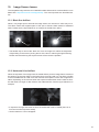
15.1 Black Sun Artifact
When a very bright spot is aimed at the image sensor, the “black sun” effect may occur.
The effect causes the brightest parts of the spot to become dark instead of saturated
white. Please see the figure below for an example of the black sun effect.
No Black Sun Artifact
with closed iris of the
lens and increased
exposure time
Black Sun
Effect
▪▪ The easiest way to remove the “black sun” from an image is to reduce the brightness
of light falling on the sensor (closing the iris of the lens or reducing the light intensity).
Please note that reducing the exposure time will not solve the problem.
15.2 Horizontal Line Artifact
When the exposure of an image frame is started while a previous image frame is read out
this action may become visible in the image frame currently read out. The effect is visible
in the line addressed for read-out at the moment the exposure of the next image frame
starts. Depending on the moment when the exposure starts within the line read-out time,
this will result in a bright or dark offset for the addressed line. See the figure below for an
example.
Horizontal
Line Artifact
▪▪ If exposure is longer than read-out time, the artifact will never be visible (there is no
line read out when exposure starts)
▪▪ Set the readout to "non overlapped"
51
16. Conformity
Cameras of the Baumer HXC family comply with:
▪▪ CE,
▪▪ FCC Part 15 Class B,
▪▪ RoHS
16.1 CE
We declare, under our sole responsibility, that the previously described Baumer HXC
cameras conform with the directives of the CE.
16.2 FCC – Class B Device
Note: This equipment has been tested and found to comply with the limits for a Class B
digital device, pursuant to part 15 of the FCC Rules. These limits are designed to provide reasonable protection against harmful interference in a residential environment. This
equipment generates, uses, and can radiate radio frequency energy and, if not installed
and used in accordance with the instructios, may cause harmful interference to radio
communications. However, there is no guarantee that interference will not occure in a
particular installation. If this equipment does cause harmful interference to radio or television reception, which can be determined by turning the equipment off an on, the user is
encouraged to try to correct the interference by one or more of the following measures:
▪▪ Reorient or relocate the receiving antenna.
▪▪ Increase the separation between the equipment and the receiver.
▪▪ Connect the equipment into an outlet on a circuit different from that to which the
receiver is connected.
▪▪ Consult the dealer or an experienced radio/TV technician for help.
52
53
Subject to change without notice. Printed in Germany 09/12 v1.4 11080602
Technical data has been fully checked, but accuracy of printed matter not guaranteed.
Baumer Optronic GmbH
Badstrasse 30
DE-01454 Radeberg, Germany
Phone +49 (0)3528 4386 0 · Fax +49 (0)3528 4386 86
[email protected] · www.baumer.com