1
Geant4 User's Guide
for Toolkit Developers
Version: geant4 9.0
Published 29 June, 2007
Geant4 Collaboration
Geant4 User's Guide for Toolkit Developers
by Geant4 Collaboration
Version: geant4 9.0
Published 29 June, 2007
Table of Contents
1. Introduction ............................................................................................................................ 1
1.1. Scope of this manual ...................................................................................................... 1
1.2. How to use this manual .................................................................................................. 1
1.3. User Requirements Document .......................................................................................... 1
2. Design and Function of Geant4 Categories ................................................................................... 2
2.1. Introduction .................................................................................................................. 2
2.2. Run ............................................................................................................................. 2
2.2.1. Design Philosophy ............................................................................................... 2
2.2.2. Class Design ...................................................................................................... 2
2.3. Event ........................................................................................................................... 2
2.3.1. Design Philosophy ............................................................................................... 2
2.3.2. Class Design ...................................................................................................... 2
2.4. Tracking ...................................................................................................................... 3
2.4.1. Design Philosophy ............................................................................................... 4
2.4.2. Class Design ...................................................................................................... 4
2.4.3. Tracking Algorithm ............................................................................................. 5
2.4.4. Interaction with Physics Processes .......................................................................... 6
2.4.5. Ordering of Methods of Physics Processes ............................................................... 8
2.5. Physics Processes .......................................................................................................... 8
2.5.1. Design Philosophy ............................................................................................... 8
2.5.2. Class Design ...................................................................................................... 9
2.6. Hits and Digitization ...................................................................................................... 9
2.6.1. Design Philosophy ............................................................................................... 9
2.6.2. Class Design ..................................................................................................... 10
2.7. Geometry ................................................................................................................... 11
2.7.1. Design Philosopy ............................................................................................... 11
2.7.2. Class Design ..................................................................................................... 11
2.7.3. Additional Geometry Diagrams ............................................................................ 13
2.8. Electromagnetic Fields .................................................................................................. 14
2.9. Particles ..................................................................................................................... 15
2.9.1. Design Philosophy ............................................................................................. 15
2.9.2. Class Design ..................................................................................................... 15
2.10. Materials ................................................................................................................... 17
2.10.1. Design Philosophy ........................................................................................... 17
2.10.2. Class Design ................................................................................................... 17
2.11. Global Usage ............................................................................................................. 18
2.11.1. Design Philosophy ........................................................................................... 18
2.11.2. Class Design ................................................................................................... 18
2.12. Visualisation .............................................................................................................. 21
2.12.1. Design Philosophy ........................................................................................... 21
2.12.2. The Graphics Interfaces .................................................................................... 21
2.12.3. The Geant4 Visualisation System ........................................................................ 22
2.12.4. Modeling sub-category ...................................................................................... 23
2.12.5. View parameters .............................................................................................. 24
2.12.6. Visualisation Attributes ..................................................................................... 24
2.13. Intercoms .................................................................................................................. 26
2.13.1. Design Philosophy ........................................................................................... 26
2.13.2. Class Design ................................................................................................... 26
3. Extending Toolkit Functionality ................................................................................................ 28
3.1. Geometry ................................................................................................................... 28
3.1.1. What can be extended ? ...................................................................................... 28
3.1.2. Adding a new type of Solid ................................................................................. 28
3.1.3. Modifying the Navigator ..................................................................................... 31
3.2. Electromagnetic Fields .................................................................................................. 31
3.2.1. Creating a New Type of Field .............................................................................. 31
iv
Geant4 User's Guide
for Toolkit Developers
3.3. Physics Processes ......................................................................................................... 34
3.4. Hadronic Physics ......................................................................................................... 34
3.4.1. Introduction ...................................................................................................... 34
3.4.2. Principal Considerations ..................................................................................... 34
3.4.3. Level 1 Framework - processes ............................................................................ 34
3.4.4. Level 2 Framework - Cross Sections and Models ..................................................... 35
3.4.5. Level 3 Framework - Theoretical Models ............................................................... 38
3.4.6. Level 4 Frameworks - String Parton Models and Intra-Nuclear Cascade ........................ 40
3.4.7. Level 5 Framework - String De-excitation} ............................................................ 41
3.5. Visualisation ............................................................................................................... 42
3.5.1. Creating a new graphics driver ............................................................................. 42
3.5.2. Enhanced Trajectory Drawing .............................................................................. 48
3.5.3. Trajectory Filtering ............................................................................................ 49
3.5.4. Other Resources ................................................................................................ 50
Bibliography ............................................................................................................................ 51
v
Chapter 1. Introduction
1.1. Scope of this manual
The User's Guide for Toolkit Developers provides detailed information about the design of Geant4 classes as well
as the information required to extend the current functionality of the Geant4 toolkit. This manual is designed to:
•
•
provide a repository of information for those who want to understand or refer to the detailed design of the
toolkit, and
provide details and procedures for extending the functionality of the toolkit so that experienced users may
contribute code which is consistent with the overall design of Geant4.
This manual is intended for developers and experienced users of Geant4. It is assumed that the reader is already
familiar with functionality of the Geant4 toolkit as explained in the ‘‘User's Guide For Application Developers",
and also has a working knowledge of programming using C++. A knowledge of object-oriented analysis and design
will also be useful in understanding this manual. It is also useful to consult the ‘‘Software Reference Manual''
which provides a list of Geant4 classes and their major methods.
Detailed discussions of the physics included in Geant4 are provided in the ‘‘Physics Reference Manual''.
1.2. How to use this manual
Part I: to understand the goal of the software design of Geant4, it is useful to begin by reading the User Requirements Document referred to in the next section.
Part II: ‘‘Design and Function of the Geant4 Categories'' provides detailed information about the design of each
class category and the classes in it. Before considering an extension of one of the toolkit categories, a detailed
understanding of that category is required.
Part III: ‘‘Extending Toolkit Functionality'' explains in some detail how to extend the functionality of Geant4.
Most of the class categories are covered and some, which are especially useful to most users, are covered in greater
detail.
It is not necessary to understand the entire manual before adding a new functionality. To add a new physics process,
for example, only the following items must be read and understood:
•
•
the design principle described in the ‘‘Physics processes'' chapter of Part II
techniques explained in the ‘‘Physics processes'' chapter of Part III.
1.3. User Requirements Document
At the beginning of Geant4 development, a set of user requirements was collected in order to inform the objectoriented analysis and design of the toolkit. The User Requirements Document follows the PSS-05 software engineering standards and is available at
http://cern.ch/geant4/OOAandD/URD.pdf .
This document provides a general description of the main capabilities and constraints of the toolkit. It also defines
three types of users characterized by their level of interaction with the system. Specific requirements are also listed
and classified.
[Status of this chapter]
24.06.05 - re-organized and re-written by D.H. Wright
1
Chapter 2.
Categories
Design and Function of Geant4
2.1. Introduction
Geant4 exploits advanced software engineering techniques based on the Booch/UML Object Oriented Methodology and follows the evolution of the ESA Software Engineering Standards for the development process. The
"spiral", or iterative, approach has been adopted. User requirements were collected in the initial phase and problem
domain decomposition, object-oriented methods, and CASE tools were used for analysis and design. This produced a clear hierarchical structure of sub-domains linked by a uni-directional flow of dependencies. This led to a
software product which is modular and flexible (a toolkit) and in which the physics implementation is transparent
and open to user validation of physics predictions. It allows the user to understand, customize and extend the
toolkit in all domains. At the same time the modular architecture allows the user to load only needed components.
2.2. Run
2.2.1. Design Philosophy
The run category manages collections of events that share a common beam and detector implementation.
2.2.2. Class Design
•
•
•
G4Run - This class represents a run. An object of this class is constructed and deleted by G4RunManager.
G4RunManager - the run controller class. Users must register detector construction, physics list and primary
generator action classes to it. G4RunManager or a derived class must be a singleton.
G4RunManagerKernel - provides control of the Geant4 kernel. This class is constructed by G4RunManager.
[Status of this chapter]
28.06.05 - under construction
December 2006 - Converted from latex to Docbook by K. Amako
2.3. Event
2.3.1. Design Philosophy
In high energy physics the primary unit of an experimental run is an event. An event consists of a set of primary
particles produced in an interaction, and a set of detector responses to these particles.
In Geant4, objects of the G4Event class are the primary units of a simulation run. Before the event is processed,
it contains primary vertices and primary particles produced by an external physics generator. After the event is
processed, it may also contain hits, digitizations ,and optionally, trajectories generated by the simulation. The
event category manages events and provides an abstract interface to external physics generators.
G4Event and its content vertices and particles are independent of other classes. This isolation allows Geant4-based
simulation programs to be independent of specific choices for physics generators and of specific solutions for
storing the ‘‘Monte Carlo truth''. G4Event avoids keeping any transient information which is not meaningful after
event processing is complete. Thus the user can store objects of this class for processing further down the program
chain. For performance reasons, G4Event and its content classes are not persistent. Instead the user must provide
the transient-to-persistent conversion.
2.3.2. Class Design
•
G4Event - This class represents an event. It is constructed and deleted by G4RunManager or its derived class.
2
Design and Function
of Geant4 Categories
•
•
G4EventManager - This class controls an event. It must be a singleton and should be constructed by
G4RunManager.
G4VPrimaryGenerator - the abstract base class of all of primary generators. This class has only one pure
virtual method, GeneratePrimaryVertex(), which takes a G4Event object, generates a primary vertex and associates primary particles with the vertex.
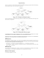
Booch diagrams for classes related to the event and event generator classes are shown in Figure 2.1 and Figure 2.2.
Figure 2.1. Event
Figure 2.2. Event Generator
[Status of this chapter]
27.06.05 design philosophy section added (from Geant4 general paper) by D.H. Wright
Dec. 2006 Conversion from latex to Docbook verson by K. Amako
2.4. Tracking
The tracking category manages the contribution of the processes to the evolution of a track's state and provides
information in sensitive volumes for hits and digitization.
3
Design and Function
of Geant4 Categories
2.4.1. Design Philosophy
It is well known that the overall performance of a detector simulation depends critically on the CPU time spent
propagating the particle through one step. The most important consideration in the object design of the tracking
category is maintaining high execution speed in the Geant4 simulation while utilizing the power of the object-oriented approach.
An extreme approach to the particle tracking design would be to integrate all functionalities required for the
propagation of a particle into a single class. This design approach looks object-oriented because a particle in the
real world propagates by itself while interacting with the material surrounding it. However, in terms of data hiding,
which is one of the most important ingredients in the object-oriented approach, the design can be improved.
Combining all the necessary functionalities into a single class exposes all the data attributes to a large number of
methods in the class. This is basically equivalent to using a common block in Fortran.
Instead of the 'big-class' approach, a hierarchical design was employed by Geant4. The hierarchical approach,
which includes inheritance and aggregation, enables large, complex software systems to be designed in a structured
way. The simulation of a particle passing through matter is a complex task involving particles, detector geometry,
physics interactions and hits in the detector. It is well-suited to the hierarchical approach. The hierarchical design
manages the complexity of the tracking category by separating the system into layers. Each layer may then be
designed independently of the others.
In order to maintain high-performance tracking, use of the inheritance ('is-a' relation) hierarchy in the tracking
category was avoided as much as possible. For example, track and particle classes might have been designed
so that a track 'is a' particle. In this scheme, however, whenever a track object is used, time is spent
copying the data from the particle object into the track object. Adopting the aggregation ('has-a' relation)
hierarchy requires only pointers to be copied, thus providing a performance advantage.
2.4.2. Class Design
Figure 2.3 shows a general overview of the tracking design in Unified Modelling Language Notation.
Figure 2.3. Tracking design
4
Design and Function
of Geant4 Categories
•
•
•
•
•
G4TrackingManager is an interface between the event and track categories and the tracking category. It handles the message passing between the upper hierarchical object, which is the event manager
(G4EventManagerz), and lower hierarchical objects in the tracking category. G4TrackingManager is
responsible for processing one track which it receives from the event manager.
G4TrackingManager aggregates the pointers to G4SteppingManager, G4Trajectory and
G4UserTrackingAction. It also has a 'use' relation to G4Track.
G4SteppingManager plays an essential role in particle tracking. It performs message passing to objects in
all categories related to particle transport, such as geometry and physics processes. Its public method Stepping() steers the stepping of the particle. The algorithm employed in this method is basically the same as
that in Geant3. The Geant4 implementation, however, relies on the inheritance hierarchy of the physics interactions. The hierarchical design of the physics interactions enables the stepping manager to handle them as
abstract objects. Hence, the manager is not concerned with concrete interaction objects such as bremsstrahlung
or pair creation. The actual invocations of various interactions during the stepping are done through a dynamic binding mechanism. This mechanism shields the tracking category from any change in the design of the
physics process classes, including the addition or subtraction of new processes.
G4SteppingManager also aggregates
• the pointers to G4Navigator from the geometry category, to the current G4Track, and
• the list of secondaries from the current track (through a G4TrackVector) to
G4UserSteppingAction and to G4VSteppingVerbose.
It also has a 'use' relation to G4ProcessManager and G4ParticleChange in the physics processes
class category.
G4Track - the class G4Track represents a particle which is pushed by G4SteppingManager. It holds
information required for stepping a particle, for example, the current position, the time since the start of stepping, the identification of the geometrical volume which contains the particle, etc. Dynamic information, such
as particle momentum and energy, is held in the class through a pointer to the G4DynamicParticle class.
Static information, such as the particle mass and charge is stored in the G4DynamicParticle class through
the pointer to the G4ParticleDefinition class. Here the aggregation hierarchical design is extensively
employed to maintain high tracking performance.
G4TrajectoryPoint and G4Trajectory - the class G4TrajectoryPoint holds the state of the particle
after propagating one step. Among other things, it includes information on space-time, energy-momentum and
geometrical volumes.
G4Trajectory aggregates all G4TrajectoryPoint objects which belong to the particle being propagated. G4TrackingManager takes care of adding the G4TrajectoryPoint to a G4Trajectory object
if the user requested it (see Geant4 User's Guide - For Application Developers. The life of a G4Trajectory
object spans an event, contrary to G4Track objects, which are deleted from memory after being processed.
G4UserTrackingAction and G4UserSteppingAction - G4UserTrackingAction is a base class from
which user actions at the beginning or end of tracking may be derived. Similarly, G4UserSteppingAction
is a base class from which user actions at the beginning or end of each step may be derived.
2.4.3. Tracking Algorithm
The key classes for tracking in Geant4 are G4TrackingManager and G4SteppingManager. The singleton
object "TrackingManager" from G4TrackingManager keeps all information related to a particular track, and
it also manages all actions necessary to complete the tracking. The tracking proceeds by pushing a particle by
a step, the length of which is defined by one of the active processes. The "TrackingManager" object delegates
management of each of the steps to the "SteppingManager" object. This object keeps all information related to
a particular step.
The public method ProcessOneTrack() in G4TrackingManager is the key to managing the tracking,
while the public method Stepping() is the key to managing one step. The algorithms used in these methods
are explained below.
ProcessOneTrack() in G4TrackingManager
1.
Actions before tracking the particle: Clear secondary particle vector
5
Design and Function
of Geant4 Categories
2.
3.
4.
5.
6.
7.
8.
Pre tracking user intervention process.
Construct a trajectory if it is requested
Give SteppingManager the pointer to the track which will be tracked
Inform beginning of tracking to physics processes
Track the particle Step-by-Step while it is alive
• Call Stepping method of G4SteppingManager
• Append a trajectory point to the trajectory object if it is requested
Post tracking user intervention process.
Destroy the trajectory if it was created
Stepping() in G4SteppingManager
1.
2.
3.
Initialize current step
If particle is stopped, get the minimum life time from all the at rest processes and invoke InvokeAtRestDoItProcs for the selected AtRest processes
If particle is not stopped:
• Invoke DefinePhysicalStepLength, that finds the minimum step length demanded by the active processes
• Invoke InvokeAlongStepDoItProcs
• Update current track properties by taking into account all changes by AlongStepDoIt
• Update the safety
• Invoke PostStepDoIt of the active discrete process.
• Update the track length
• Send G4Step information to Hit/Dig if the volume is sensitive
• Invoke the user intervention process.
• Return the value of the StepStatus.
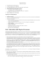
2.4.4. Interaction with Physics Processes
The interaction of the tracking category with the physics processes is done in two ways. First each process can limit
the step length through one of its three GetPhysicalInteractionLength() methods, AtRest, AlongStep,
or PostStep. Second, for the selected processes the DoIt (AtRest, AlongStep or PostStep) methods are invoked.
All this interaction is managed by the Stepping method of G4SteppingManager. To calculate the step length,
the DefinePhysicalStepLength() method is called. The flow of this method is the following:
•
•
•
Obtain maximum allowed Step in the volume define by the user through G4UserLimits.
The PostStepGetPhysicalInteractionLength of all active processes is called. Each process returns a step length
and the minimum one is chosen. This method also returns a G4ForceCondition flag, to indicate if the process is
forced or not: = Forced : Corresponding PostStepDoIt is forced. = NotForced : Corresponding PostStepDoIt is
not forced unless this process limits the step. = Conditionally : Only when AlongStepDoIt limits the step, corresponding PoststepDoIt is invoked. = ExclusivelyForced : Corresponding PostStepDoIt is exclusively forced.
All other DoIt including AlongStepDoIts are ignored.
The AlongStepGetPhysicalInteractionLength method of all active processes is called. Each process returns a
step length and the minimum of these and the This method also returns a fGPILSelection flag, to indicate if the
process is the selected one can be is forced or not: = CandidateForSelection: this process can be the winner. If
its step length is the smallest, it will be the process defining the step (the process = NotCandidateForSelection:
this process cannot be the winner. Even if its step length is taken as the smallest, it will not be the process
defining the step
The method G4SteppingManager::InvokeAlongStepDoIts() is in charge of calling the AlongStepDoIt methods of the different processes:
•
•
If the current step is defined by a 'ExclusivelyForced' PostStepGetPhysicalInteractionLength, no AlongStepDoIt method will be invoked
Else, all the active continuous processes will be invoked, and they return the ParticleChange. After it for each
process the following is executed:
• Update the G4Step information by using final state information of the track given by a physics process.
This is done through the UpdateStepForAlongStep method of the ParticleChange
6
Design and Function
of Geant4 Categories
•
•
Then for each secondary:
• It is checked if its kinetic energy is smaller than the energy threshold for the material. In this case the
particle is assigned a 0. kinetic energy and its energy is added as deposited energy of the parent track.
This check is only done if the flag ApplyCutFlag is set for the particle (by default it is set to 'false' for all
particles, user may change it in its G4VUserPhysicsList). If the track has the flag IsGoodForTracking
'true' this check will have no effect (used mainly to track particles below threshold)
• The parentID and the process pointer which created this track are set
• The secondary track is added to the list of secondaries. If it has 0. kinetic energy, it is only added if it
it invokes a rest process at the beginning of the tracking
The track status is set according to what the process defined
The method G4SteppingManager::InvokePostStepDoIts is on charge of calling the PostStepDoIt
methods of the different processes.
•
Invoke the PostStepDoIt methods of the specified discrete process (the one selected by the PostStepGetPhysicalInteractionLength, and they return the ParticleChange. The order of invocation of processes is inverse to
the order used for the GPIL methods. After it for each process the following is executed:
• Update PostStepPoint of Step according to ParticleChange
• Update G4Track according to ParticleChange after each PostStepDoIt
• Update safety after each invocation of PostStepDoIts
• The secondaries from ParticleChange are stored to SecondaryList
• Then for each secondary:
• It is checked if its kinetic energy is smaller than the energy threshold for the material. In this case the
particle is assigned a 0. kinetic energy and its energy is added as deposited energy of the parent track.
This check is only done if the flag ApplyCutFlag is set for the particle (by default it is set to 'false' for all
particles, user may change it in its G4VUserPhysicsList). If the track has the flag IsGoodForTracking
'true' this check will have no effect (used mainly to track particles below threshold)
• The parentID and the process pointer which created this track are set
• The secondary track is added to the list of secondaries. If it has 0. kinetic energy, it is only added if it
it invokes a rest process at the beginning of the tracking
• The track status is set according to what the process defined
The method G4SteppingManager::InvokeAtRestDoIts is called instead of the three above methods in
case the track status is fStopAndALive. It is on charge of selecting the rest process which has the shortest time
before and then invoke it:
•
•
•
To select the process with shortest tiem, the AtRestGPIL method of all active processes is called. Each process
returns an lifetime and the minimum one is chosen. This method returm also a G4ForceCondition flag, to
indicate if the process is forced or not: = Forced : Corresponding AtRestDoIt is forced. = NotForced : Corresponding AtRestDoIt is not forced unless this process limits the step.
Set the step length of current track and step to 0.
Invoke the AtRestDoIt methods of the specified at rest process, and they return the ParticleChange. The order
of invocation of processes is inverse to the order used for the GPIL methods.
After it for each process the following is executed:
• Set the current process as a process which defined this Step length.
• Update the G4Step information by using final state information of the track given by a physics process.
This is done through the UpdateStepForAtRest method of the ParticleChange.
• The secondaries from ParticleChange are stored to SecondaryList
• Then for each secondary:
• It is checked if its kinetic energy is smaller than the energy threshold for the material. In this case the
particle is assigned a 0. kinetic energy and its energy is added as deposited energy of the parent track.
This check is only done if the flag ApplyCutFlag is set for the particle (by default it is set to 'false' for all
particles, user may change it in its G4VUserPhysicsList). If the track has the flag IsGoodForTracking
'true' this check will have no effect (used mainly to track particles below threshold)
• The parentID and the process pointer which created this track are set
• The secondary track is added to the list of secondaries. If it has 0. kinetic energy, it is only added if it
it invokes a rest process at the beginning of the tracking
• The track is updated and its status is set according to what the process defined
7
Design and Function
of Geant4 Categories
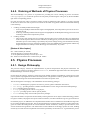
2.4.5. Ordering of Methods of Physics Processes
The ProcessManager of a particle is responsible for providing the correct ordering of process invocations.
G4SteppingManager invokes the processes at each phase just following the order given by the ProcessManager of the corresponding particle.
For some processes the order is important. Geant4 provides by default the right ordering. It is always possible
for the user to choose the order of process invocations at the initial set up phase of Geant4. This default ordering
is the following:
1.
2.
Ordering of GetPhysicalInteractionLength
• In the loop of GetPhysicalInteractionLength of AlongStepDoIt, the Transportation process has to be invoked at the end.
• In the loop of GetPhysicalInteractionLength of AlongStepDoIt, the Multiple Scattering process has to be
invoked just before the Transportation process.
Ordering of DoIts
• There is only some special cases. For example, the Cherenkov process needs the energy loss information
of the current step for its DoIt invocation. Therefore, the EnergyLoss process has to be invoked before the
Cherenkov process. This ordering is provided by the process manager. Energy loss information necessary
for the Cherenkov process is passed using G4Step (or the static dE/dX table is used together with the step
length information in G4Step to obtain the energy loss information). Any other?
[Status of this chapter]
Nov. 1998 created by K. Amako
10.06.02 partially re-written by D.H. Wright
14.11.02 updated and partially re-written by P. Arce
Dec. 2006 Converted from latex to Docbook by K. Amako
2.5. Physics Processes
2.5.1. Design Philosophy
The processes category contains the implementations of particle transportation and physical interactions. All
physics process conform to the basic interface G4VProcess, but different approaches have been developed for
the detailed design of each sub-category.
For the decay sub-category, the decays of all long-lived, unstable particles are handled by a single process. This
process gets the step length from the mean life of the particle. The generation of decay products requires a knowledge of the branching ratios and/or data distributions stored in the particle class.
The electromagnetic sub-category is divided further into the following packages:
•
•
•
•
•
•
standard: handling basic properties for electron, positron, photon and hadron interactions,
low energy: providing alternative models extended down to lower energies than the standard package,
muons: handling muon interactions,
x-rays: providing specific code for x-ray physics,
optical: providing specific code for optical photons,
utils: collecting utility classes used by the above packages.
It provides the features of openness and extensibilty resulting from the use of object-oriented technology; alternative physics models, obeying the same process abstract interface, are often available for a given type of interaction.
For hadronic physics, an additional set of implementation frameworks was added to accommodate the large number of possible modeling approaches. The top-level framework provides the basic interface to other Geant4 categories. It satisfies the most general use-case for hadronic shower simulations, namely to provide inclusive cross
sections and final state generation. The frameworks are then refined for increasingly specific use-cases, building
a hierarchy in which each level implements the interface specified by the level above it. A given hadronic process
8
Design and Function
of Geant4 Categories
may be implemented at any one of these levels. For example, the process may be implemented by one of several
models, and each of the models may in turn be implemented by several sub-models at the lower framework levels.
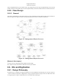
2.5.2. Class Design
2.5.2.1. General
The object-oriented design of the generic physics process G4VProcess and its relation to the process manager is
shown in Figure 2.4. Figure 2.5 shows how specific physics processes are related to G4VProcess.
Figure 2.4. Management of Physics Processes
Figure 2.5. Management of Physics Processes
[Status of this chapter]
27.06.05 section on design philosophy added by D.H. Wright
Dec. 2006 Conversion from latex to Docbook verson by K. Amako
2.6. Hits and Digitization
2.6.1. Design Philosophy
In Geant4 a hit is a snapshot of a physical interaction or an accumulation of interactions of a track or tracks in a
‘‘sensitive'' detector component. A digitization, or digit, represents a detector output, such as an ADC/TDC count
or a trigger signal. A digit is created from one or more hits and/or other digits.
9
Design and Function
of Geant4 Categories
Given the wide variety of Geant4 applications, ways of describing detector sensitivity and the quantities to be
stored in the hits and digits vary greatly. This category therefore provides only abstract classes for both detector
sensitivity and hits/digits. It also provides tools for organizing the hits/digits into collections.
2.6.2. Class Design
•
•
•
•
•
•
•
•
•
G4SensitiveDetectorManager - a list of G4SensitiveDetectors.
G4HitsStructure - a tree-like structure of G4Hit collections. Each branch represents the hits in given sub-detector. For example, the first level of branches may consist of a tracker, ECAL, and HCAL, while the second
level, in HCAL, consists of the barrel and endcaps. Finally the barrel may have phi-slices, Z-slices, etc.
G4VSensitiveDetector - an abstract class of all of sensitive volumes.
G4HitsCollection - a collection of hits. Instantiates an RWCollection class.
G4VHit - this class has all the information about a particular hit caused by a single step.
G4VDigitizer - the class of objects which transform the hits deposited by particles into digitizations.
G4DigitizerManager - the (single) object dispatching common messages to individual digitizers.
G4VDigi - an abstract (base) class for all G4 digitizations. This could be data as simple as a singe byte, or
as complex as an Ntuple.
G4DigiStructure - digitizations are organized as a structure, which could be anything between a single value
and an Ntuple.
The object-oriented design of the 'hit' related classes is shown in the following class diagrams. The diagrams are
described in the Booch notation. Figure 2.6 shows the general management of hit classes. Figure 2.7 shows the
OO design of user-related hit classes. Figure 2.8 shows the OO design of the readout geometry.
Figure 2.6. Overview of hit classes management
Figure 2.7. User hit classes
10
Design and Function
of Geant4 Categories
Figure 2.8. Readout geometry
[Status of this chapter]
27.06.05 section on design philosophy added (from Geant4 general paper) by D.H. Wright
Dec. 2006 Conversion from latex to Docbook verson by K. Amako
2.7. Geometry
2.7.1. Design Philosopy
The geometry category provides the ability to describe a geometrical structure and propagate particles efficiently
through it. This is done in part with the aid of two central concepts, the logical and physical volumes. A logical
volume represents a detector element of a given shape which may contain other volumes, and which may have
other attributes. It has access to other information which is independent of its phyisical location in the detector,
such as material and sensitive detector behavior. A physical volume represents the spatial positioning or placement
of the logical volume with respect to an enclosing mother (logical) volume. Thus a hierarchical tree structure of
volumes can be built with each volume containing smaller volumes (which may not overlap). Repetitive structures
can be represented by specialized physical volumes, such as replicas and parameterized placements, sometimes
resulting in a large savings in memory.
In Geant4 the logical volume has been refined by defining the shape as a separate entity, called a solid. Solids
with simple shapes, like rectilinear boxes, trapezoids, spherical or cylindrical sections or shells, each have their
properties coded separately, in accord with the concept of Constructed Solid Geometry (CSG). More complex
solids are defined by their bounding surfaces, which can be planes, second-order surfaces or higher-order B-spline
surfaces, and belong to the Boundary Representations (BREP) sub-category.
Another way to build solids is by boolean combination - union, intersection and subtraction. The elemental solids
should be CSGs.
Although a detector is naturally and best described as by a hierarchy of volumes, efficiency is not critically dependent on this. An optimization technique, called voxelization, allows efficient navigation even in ‘‘flat'' geometries,
typical of those produced by CAD systems.
2.7.2. Class Design
•
G4GeometryManager - responsible for managing ‘‘high level'' objects in the geometry subdomain, notably
including opening and closing (‘‘locking'') the geometry, and creating/deleting optimization information for
G4Navigator. The class is a "singleton".
11
Design and Function
of Geant4 Categories
•
•
•
•
•
•
•
•
•
•
•
•
•
•
•
•
•
•
•
•
•
•
•
G4LogicalVolumeStore - a container for optionally storing created logical volumes. It enables traversal of
all logical volumes by the UI/user/etc.
G4LogicalVolume - represents a leaf node or unpositioned subtree in the geometry hierarchy. It may have
daughters ascribed to it, and is also responsible for retrieval of the physical and tracking attributes of the
physical volume that it represents. These attributes include solid, material, magnetic field, and optionally user
limits, sensitive detectors, etc. Logical volumes are optionally entered into the G4LogicalVolumeStore.
G4MagneticField - a class responsible for the magnetic field in each volume, including the calculation of
particle trajectories along curved paths. In cases where the geometry step limits the particle's step, the distance
calculated is guaranteed to be the distance to a volume boundary.
G4Navigator - a class used by the tracking management, able to obtain/calculate tracking-time geometrical
information such as distance to the next volume, or to find the physical volume containing a given point in
the world reference system. The navigator maintains a transformation history and other information used to
optimize the tracking time performance.
G4NavigationHistory - responsible for maintenance of the history of the path taken through the geometrical
hierarchy. It is principally a utility class for use by G4Navigator.
G4NormalNavigation - a utility class for navigation in volumes containing only G4PVPlacement daughter
volumes.
G4ParameterisedNavigation - a utility class for navigation in volumes containing a single
G4PVParameterised volume for which voxels for the replicated volumes have been constructed.
G4VoxelNavigation - a utility class for navigation in volumes containing only G4PVPlacement daughter
volumes for which voxels have been constructed.
G4ReplicaNavigation - a utility class for navigation in volumes containing a single G4PVParameterised volume for which voxels for the replicated volumes have been constructed.
G4PhysicalVolumeStore - a container for optionally storing created physical volumes. It enables traversal
of all physical volumes by the UI/user/etc. All solids should be registered with G4PhysicalVolumeStore, and
removed on their destruction. It is intended principally for the UI browser.
G4VPhysicalVolume - a volume positioned within and relative to a given mother volume, and also represented
by a given logical volume. They are optionally entered into the G4PhysicalVolumeStore.
G4PVPlacement - a physical volume corresponding to a single touchable detector element, positioned within
and relative to a mother volume.
G4PVIndexed - a volume able to perform simple changes to its shape (corresponds to GSPOSP), and representing a single touchable detector element.
G4PVReplica - a physical volume representing many identically formed touchable detector elements, differing only in their positioning. The elements' positions are determined by means of a simple formula, and the
elements completely fill the containing mother volume.
G4PVParameterised - a physical volume representing many touchable detector elements differing in their
positioning and dimensions. Both are calculated by means of a G4VParameterisation object. Each element's
position is calculated as per G4PVReplica, and each element's shape can be modified by means of a user
supplied formula.
G4VPVParameterisation - a parameterisation class able to compute the transformation and, indirectly, the
dimensions of parameterised volumes, given a replication number.
G4SmartVoxelProxy - a class for proxying smart voxels. The class represents either a header (in turn refering
to more VoxelProxies) or a node. If created as a node, calls to GetHeader cause an exception, and likewise
GetNode when a header.
G4SmartVoxelHeader - represents a single axis of virtual division. Contains the individual divisions which
are potentially further divided along different axes.
G4SmartVoxelNode - a single virtual division, containing the physical volumes inside its boundaries and
those of its parents.
G4VoxelLimits - represents limitation/restrictions of space, where restrictions are only made perpendicular
to the cartesian axes.
G4RotationMatrixStore - a container for optionally storing created G4RotationMatrices.
G4SolidStore - a container for optionally storing created solids. It enables traversal of all/any solids by the
UI/user/etc. The class is a "singleton".
G4VSolid - position independent geometrical entities. They have only ‘shape', and encompass both CSG and
boundary representations. They are optionally entered into the G4SolidStore. This class defines, but does not
12
Design and Function
of Geant4 Categories
•
•
•
•
•
•
•
•
•
•
implement, functions to compute distances to/from the shape. Functions are also defined to check whether a
point is inside the shape, to return the surface normal of the shape at a given point, and to compute the extent
of the shape.
G4VSweptSolid - a solid created by performing a 3D transformation on a finite planar face.
G4HalfSpaceSolid - a solid created by the boolean AND of one or more half space surfaces.
G4BREPSolid - a solid created by an abitrary set of finite surfaces.
G4VTouchable - a class that maintains a ‘‘reference'' on a given touchable element of the detector - a kind of
bookmark. It enables a given detector element to be saved during tracking (in case of booleans/user code/etc.)
and the corresponding G4PhysicalVolume retrieved later, with its ‘‘state'' information (path through the tree)
optionally restored so that navigation can be restarted. G4Touchables provide fast access to the transformation
from the global reference system to that of the saved detector element.
G4TouchableHistory - object representing a touchable detector element, and its history in the geomtrical
hierarchy, including its net resultant local->global transform.
G4GRSSolid} - object representing a touchable solid. It maintains the association between a solid and its net
resultant local-to-global transform.
G4GRSVolume - object representing a touchable detector element. It maintains associations between a physical volume and its net resultant local-to-global transform.
G4TransformStore - a container for optionally storing created G4AffineTransform objects. It is responsible
for storing and providing access to transformations that are constant at tracking time.
G4AffineTransform - a class for geometric affine transformations. It supports efficient arbitrary rotation and
transformation of vectors and the computation of compound and inverse transformations. A ‘‘rotation flag'' is
maintained internally for greater computational efficiency for transforms that do not involve rotation.
G4UserLimits - responsible for user limits on step size, ascribable to individual volumes.
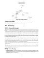
Figure 2.9 shows a general overview, in UML notation, of the geometry design. A detailed collection of class
diagrams from the geometry category is found in the Appendix.
Figure 2.9. Overview of the geometry
2.7.3. Additional Geometry Diagrams
Additional diagrams for the object-oriented design of the 'geometry' related classes are included here.
Figure 2.10 shows the class diagram for smart voxels. Figure 2.11 shows the class diagram for the navigator.
13
Design and Function
of Geant4 Categories
Figure 2.10. Class diagram for smart voxels
Figure 2.11. Class diagram for the navigator
[Status of this chapter]
27.06.05 subsection on design philosphy (from Geant4 general paper) added by D.H. Wright
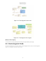
2.8. Electromagnetic Fields
The object-oriented design of the classes related to the electromagnetic field is shown in the class diagram of
Figure 2.12. The diagram is described in UML notation.
14
Design and Function
of Geant4 Categories
Figure 2.12. Electromagnetic Field
2.9. Particles
2.9.1. Design Philosophy
The particles category implements the facilities necessary to describe the physical properties of particles for the
simulation of particle-matter interactions. All particles are based on the G4ParticleDefinition class, which describes basic properties such as mass, charge, etc., and also allows the particle to carry a list of processes to which
it is sensitive. A first-level extension of this class defines the interface for particles that carry cuts information, for
example range cut versus energy cut equivalence. A set of virtual, intermediate classes for leptons, bosons, mesons,
baryons, etc., allows the implementation of concrete particle classes which define the actual particle properties
and, in particular, implement the actual range versus energy cuts equivalence. All concrete particle classes are
instantiated as singletons to ensure that all physics processes refer to the same particle properties.
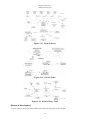
2.9.2. Class Design
The object-oriented design of the 'particles' related classes is shown in the following class diagrams. The diagrams
are described in the Booch notation. Figure 2.13 shows a general overview of the particle classes. Figure 2.14
shows classes related to the particle table. Figure 2.15 shows the classes related to the particle decay table.
15
Design and Function
of Geant4 Categories
Figure 2.13. Particle classes
Figure 2.14. Particle Table
Figure 2.15. Particle Decay Table
[Status of this chapter]
27.06.05 section on design philosophy added (from Geant4 general paper) by D.H. Wright
16
Design and Function
of Geant4 Categories
Dec. 2006 Conversion from latex to Docbook verson by K. Amako
2.10. Materials
2.10.1. Design Philosophy
The design of the materials category reflects what exists in nature: materials are made of a single element or a
mixture of elements, and elements are made of a single isotope or a mixture of isotopes. Because the physical
properties of materials can be described in a generic way by quantities which can be specified directly, such as
density, or derived from the element composition, only concrete classes are necessary in this category.
The material category implements the facilities necessary to describe the physical properties of materials for the
simulation of particle-matter interactions. Characteristics like radiation and interaction length, excitation energy
loss, coefficients in the Bethe-Bloch formula, shell correction factors, etc., are computed from the element, and
if necessary, the isotope composition.
The material category also implements facilities to describe surface properties used in the tracking of optical
photons.
2.10.2. Class Design
The object-oriented design of the 'materials' related classes is shown in the class diagram: Figure 2.16. The diagram
is described in the Booch notation.
Figure 2.16.
[Status of this chapter]
27.06.05 section on design philosophy add (from Geant4 general paper) by D.H. Wright
Dec. 2006 Conversion from latex to Docbook verson by K. Amako
17
Design and Function
of Geant4 Categories
2.11. Global Usage
2.11.1. Design Philosophy
The global category covers the system of units, constants, numerics and random number handling. It can be considered a place-holder for "general purpose" classes used by all categories defined in Geant4. No back-dependencies to other Geant4 categories affect the "global" domain. There are direct dependencies of the global category
on external packages, such as CLHEP, STL, and miscellaneous system utilities.
Within the management sub-category are ‘‘utility'' classes generally used within the Geant4 kernel. They are, for
the most part, uncorrelated with one another and include:
•
•
•
•
•
•
•
G4Allocator
G4FastVector
G4ReferenceCountedHandle
G4PhysicsVector, G4LPhysicsFreeVector, G4PhysicsOrderedFreeVector
G4Timer
G4UserLimits
G4UnitsTable
A general description of these classes is given in section 3.2 of the Geant4 User's Guide for Application Developers.
In applications where it is necessary to generate random numbers (normally from the same engine) in many different methods and parts of the program, it is highly desirable not to rely on or require knowledge of the global
objects instantiated. By using static methods via a unique generator, the randomness of a sequence of numbers
is best assured. Hence the use of a static generator has been introduced in the original design of HEPRandom as
a project requirement in Geant4.
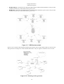
2.11.2. Class Design
Analysis and design of the HEPRandom module have been achieved following the Booch Object-Oriented methodology. Some of the original design diagrams in Booch notation are reported below. Figure 2.17 is a general picture
of the static class diagram.
•
•
•
•
•
•
•
•
•
•
HepRandomEngine - abstract class defining the interface for each Random engine. Its pure virtual methods
must be defined by its subclasses representing the concrete Random engines.
HepJamesRandom - class inheriting from HepRandomEngine and defining a flat random number generator
according to the algorithm described in "F.James, Comp.Phys.Comm. 60 (1990) 329". This class is instantiated
by default as the default random engine.
DRand48Engine - class inheriting from HepRandomEngine and defining a flat random number generator
according to the drand48() and srand48() system functions from the C standard library.
RandEngine - class inheriting from HepRandomEngine and defining a flat random number generator according to the rand() and srand() system functions from the C standard library.
RanluxEngine - class inheriting from HepRandomEngine and defining a flat random number generator according to the algorithm described in "F.James, Comp.Phys.Comm. 60 (1990) 329-344" and originally implemented in FORTRAN 77 as part of the MATHLIB HEP library. It provides 5 different "luxury" levels [0..4].
RanecuEngine - class inheriting from HepRandomEngine and defining a flat random number generator according to the algorithm RANECU originally written in FORTRAN 77 as part of the MATHLIB HEP library.
It uses a table of seeds which provides uncorrelated couples of seed values.
HepRandom - the main class collecting all the methods defining the different random generators applied to
HepRandomEngine. It is a singleton class which all the distribution classes derive from. This singleton is
instantiated by default.
RandFlat - distribution class for flat random number generation. It also provides methods to fill an array of
flat random values, given its size or shoot bits.
RandExponential - distribution class defining exponential random number distribution, given a mean. It also
provides a method to fill an array of flat random values, given its size.
RandGauss - distribution class defining Gauss random number distribution, given a mean or specifying also
a deviation. It also provides a method to fill an array of flat random values, given its size.
18
Design and Function
of Geant4 Categories
•
•
RandBreitWigner - distribution class defining the Breit-Wigner random number distribution. It also provides
a method to fill an array of flat random values, given its size.
RandPoisson - distribution class defining Poisson random number distribution, given a mean. It also provides
a method to fill an array of flat random values, given its size.
Figure 2.17. HEPRandom module
Figure 2.18 is a dynamic object diagram illustrating the situation when a single random number is thrown by the
static generator according to one of the available distributions. Only one engine is assumed to active at a time.
Figure 2.18. Shooting via the generator
19
Design and Function
of Geant4 Categories
Figure 2.19 illustrates a random number being thrown by explicitly specifying an engine which can be shared by
many distribution objects. The static interface is skipped here.
Figure 2.19. Shooting via distribution objects
Figure 2.20 illustrates the situation when many generators are defined, each by a distribution and an engine. The
static interface is skipped here.
Figure 2.20. Shooting with arbitrary engines
For detailed documentation about the HEPRandom classes see the CLHEP Reference Guide(http://cern.ch/clhep/
manual/RefGuide) or the CLHEP User Manua(http://cern.ch/clhep/manual/UserGuide).
Informations written in this manual are extracted from the original manifesto distributed with the HEPRandom
package (http://cern.ch/clhep/manual/UserGuide/Random/Random.html).
HEPNumerics
The HEPNumerics module includes a set of classes which implement numerical algorithms for general use in
Geant4. The User's Guide for Application Developers contains a description of each class. Most of the algorithms
were implemented using methods from the following books:
•
•
B.H. Flowers, "An introduction to Numerical Methods In C++", Claredon Press, Oxford 1995.
M. Abramowitz, I. Stegun, "Handbook of mathematical functions", DOVER Publications INC, New York
1965 ; chapters 9, 10, and 22.
HEPGeometry
Documentation for the HEPGeometry module is provided in the CLHEP Reference Guide(http://cern.ch/clhep/
manual/RefGuide) or the CLHEP User Manual(http://cern.ch/clhep/manual/UserGuide).
[Status of this chapter]
01.12.02 minor update by G. Cosmo
20
Design and Function
of Geant4 Categories
18.06.05 introductory paragraphs added and minor grammar changes by D.H. Wright
Dec. 2006 Conversion from latex to Docbook verson by K. Amako
2.12. Visualisation
2.12.1. Design Philosophy
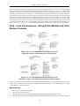
The visualisation category consists of the classes required to display detector geometry, particle trajectories, tracking steps, and hits. It also provides visualisation drivers, which are interfaces to external graphics systems.
A wide variety of user requirements went into the design of the visualisation category, for example:
•
•
•
•
•
•
•
very quick response in surveying successive events,
high-quality output for presentation and documentation,
flexible camera control for debugging detector geometry and physics,
selection of visualisable objects,
interactive picking of graphical objects for attribute editing or feedback to the associated data,
highlighting incorrect intersections of physical volumes,
co-working with graphical user interfaces.
Because it is very difficult to respond to all of these requirements with only one built-in visualiser, an abstract
interface was developed which supports several complementary graphics systems. Here the term graphics system
means either an application running as a process independent of Geant4 or a graphics library to be compiled with
Geant4. A concrete implementation of the interface is called a visualisation driver, which can use a graphics
library directly, communicate with an independent process via pipe or socket, or simply write an intermediate file
for a separate viewer.
2.12.2. The Graphics Interfaces
•
G4VVisManager: All user code writes to the graphics systems through this pure abstract interface. It contains
Draw methods for all the graphics primitives in the graphics_reps category (G4Polyline, G4Circle, etc.), geometry objects (through their base classes, G4VSolid, G4PhysicalVolume and G4LogicalVolume) and hits
and trajectories (through their base classes, G4VHit and G4VTrajectory).
Since this is an abstract interface, all user code must check that there exists a concrete instantiation of it. A
static method is provided, so a typical user code fragment is:
G4VVisManager* pVVisManager = G4VVisManager::GetConcreteInstance();
if(pVVisManager) {
pVVisManager->Draw(G4Circle...
...
Note that this allows the building an application without a concrete implementation, for example for a batch
job, even if some code, like the above, is still included. Most of the novice examples can be built this way
if G4VIS_NONE is specified.
•
The concrete implementation of this interface is hereafter referred to as the visualisation manager.
G4VGraphicsScene: The visualisation manager must also provide a concrete implementation of the subsidiary
interface, G4VGraphicsScene. It is only for use by the kernel and the modeling category. It offers direct access
to a ‘‘scene handler'' through a reference provided by the visualisation manager. It is described in more detail
in the section on extending the toolkit functionality.
The Geant4 distribution includes implementations of the above interfaces, namely G4VisManager and
G4VSceneHandler respectively, and their associated classes. These define further abstract base classes for visualisation drivers. Together they form the Geant4 Visualisation System. A variety of concrete visualisation drivers
are also included in the distribution. Details of how to implement a visualisation driver are given in Section 3.5. Of
21
Design and Function
of Geant4 Categories
course, it is always possible for a user to implement his or her own concrete implementations of G4VVisManager
and G4VGraphicsScene replacing the Geant4 Visualisation System altogether.
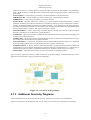
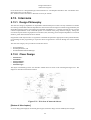
2.12.3. The Geant4 Visualisation System
The Geant4 Visualisation System consists of
•
•
•
•
•
•
G4VisManager: An implementation of the G4VVisManager interface. It manages multiple graphics systems
and defines three more concepts -- the scene (G4Scene), the scene handler (base class G4VSceneHandler,
itself a sub-class of G4VGraphicsScene) and the viewer (base class G4VViewer) -- see below. G4VisManager
is a singleton and an abstract class, requiring the user to derive from it a concrete visualisation manager
(G4VisExecutive is provided -- see below). Roles and structure of the visualisation manager are described in
Chapter 8 of the User's Guide for Application Developers.
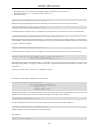
G4VisExecutive: A concrete visualisation manager that implements the virtual functions RegisterGraphicsSystems and RegisterModelFactories. These functions must be in the users' domain, since the graphics systems and models that are instantiated by them are, in many cases, provided by the user (graphics libraries,
etc.). It is therefore implemented as a .hh-.icc combination that is designed to be included in the users' code.
Of course, the user may write his or her own.
G4Scene The scene is a list if models for physical volumes, axes, hits, trajectories, etc. - see Section Section 2.12.4. They are distinguished according to their lifetime -- ‘‘run-duration'' for physical volumes, etc.,
‘‘end-of-event'' for hits and trajectories, etc. The end-of-event models are only to be used when the Geant4
state indicates the end of event has been reached. The scene has an extent (G4VisExtent), which is updated
by the scene when a new model is added (each model itself has an extent), and a ‘‘standard'' target point; these
are used to define the standard view -- see below. In addition, the scene keeps flags which indicate whether
end-of-event objects should be accumulated or refreshed for each event or run.
G4VGraphicsSystem: This is an abstract base class for scene handler and viewer factories. It is used by the
visualisation manager to create scene handlers and viewers on request.
G4VSceneHandler: A sub-class of G4VGraphicsScene, itself an abstract base class for specific scene handlers, whose job is to convert the scene into graphics-system-specific code for the viewer. For example, the
scene handler may create a graphical database, taking care to separate run-duration (persistent) and end-ofevent (transient) information (this is described further in Section 3.5.1.6.
G4VViewer: An abstract base class for specific viewers. Its job is to create windows or files and identify where
and how the final view should be rendered. It has view parameters (G4ViewParameters) which specify viewpoint direction, type of rendering (wireframe or surface), etc. It is the view's responsibility, noting the scene's
extent and target point, to choose a camera position and magnification that ensures that the scene is automatically and comfortably rendered in the viewing window. This is then the standard view, and any further operations requested by the user - zoom, pan, etc. - are relative to this standard view. The class G4ViewParameters
has utility routines to assist this procedure; it is strongly advised that toolkit developers writing a viewer should
study the G4ViewParameters class, whose header file contains much useful information (also preserved in the
Software Reference Manual).
The viewer is messaged by the vis manager when the user issues commands, such as /vis/viewer/refresh. This invokes methods such as SetView, ClearView and DrawView. A detailed description of the call
sequences is given in Section 3.5.1.2- Section 3.5.1.5.
Note there is no restriction on the number or type of scene handlers or viewers. There may be several scene
handlers processing the same or different scenes, each with several viewers (for example, the same scene from
differing viewpoints).
By defining a set of three C++ classes inheriting from the virtual base classes - G4VGraphicsSystem,
G4VSceneHandler and G4VViewer - an arbitrary graphics system can easily be plugged in to Geant4. The
plugged-in graphics system is then available for visualising detector simulations. Together, this set of three concrete classes is called a "visualisation driver". The DAWN-File driver, for example, is the interface to the Fukui
Renderer DAWN, and is implemented by the following set of classes:
1.
2.
G4DAWNFILE : public G4VGraphicsSystem for creation of the scene handlers and viewers
G4DAWNFILESceneHandler : public G4VSceneHandler for modeling 3D scenes
22
Design and Function
of Geant4 Categories
3.
G4DAWNFILEView : public G4VView for rendering 3D scenes
Several visualisation drivers are distributed with Geant4. They are complementary to each other in many aspects.
For details, see Chapter 8 of the User's Guide for Application Developers.
2.12.4. Modeling sub-category
•
G4VModel - a base class for visualisation models. A model is a graphics-system-independent description of
a Geant4 component.
The sub-category visualisation/modeling defines how to model a 3D scene for visualisation. The term "3D
scene" indicates a set of visualisable component objects put in a 3D world. A concrete class inheriting from
the abstract base class G4VModel defines a "model", which describes how to visualise the corresponding
component object belonging to a 3D scene. G4ModelingParameters defines various associated parameters.
For example, G4PhysicalVolumeModel knows how to visualise a physical volume. It describes a physical
volume and its daughters to any desired depth. G4HitsModel knows how to visualise hits. G4TrajectoriesModel
knows how to visualise trajectories.
The main task of a model is to describe itself to a 3D scene by giving a concrete implementation of the following
virtual method of G4VModel:
virtual void DescribeYourselfTo (G4VGraphicsScene&) = 0;
The argument class G4VGraphicsScene is a minimal abstract interface of a 3D scene for the Geant4 kernel
defined in the graphics_reps category. Since G4VSceneHandler and its concrete descendants inherit from
G4VGraphicsScene, the method DescribeYourselfTo() can pass information of a 3D scene to a visualisation
driver.
•
It is easy for a toolkit developer of Geant4 to add a new kind of visualisable component object. It is done by
implementing a new class inheriting from G4VModel.
G4VTrajectoryModel - an abstract base class for trajectory drawing models.
A trajectory model governs how an individual trajectory is drawn. Concrete models inheriting from
G4VTrajectoryModel must implement two pure virtual functions:
virtual void Draw(const G4VTrajectory&, G4int i_mode = 0) const = 0;
virtual void Print(std::ostream& ostr) const = 0;
•
See for example G4TrajectoryDrawByParticleID.
G4VModelFactory - an abstract base class for factories creating models and associated messengers.
It is not necessary to generate messengers for a trajectory model that will be constructed and configured directly
in compiled code. If the user requires model creation and configuration features through interactive commands,
however, there must be a mechanism to generate both models and their associated messengers. This is the
role of G4VModelFactory. Concrete factories inheriting from G4VModelFactory are responsible for creating
a concrete model and concrete messengers. To help ensure a type safe messenger to model interaction on the
command line, the messengers should inherit from G4VModelCommand.
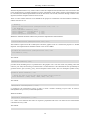
Concrete factories must implement one pure virtual function:
virtual ModelAndMessengers
Create(const G4String& placement, const G4String& modelName) = 0;
23
where placement indicates which directory space the commands should occupy. See for example
G4TrajectoryDrawByParticleIDFactory.
Design and Function
of Geant4 Categories
2.12.5. View parameters
View parameters such as camera parameters, drawing styles (wireframe/surface etc) are held by
G4ViewParameters. Each viewer holds a view parameters object which can be changed interactively and a default
object (for use in the /vis/viewer/reset command).
If a toolkit developer of Geant4 wants to add entries of view parameters, he should add fields and methods to
G4ViewParameters.
2.12.6. Visualisation Attributes
All drawable objects (should) have a method:
const G4VisAttributes* GetVisAttributes() const;
A drawable object might be:
•
•
a "visible" (i.e., inheriting G4Visible), such as a polyhedron, polyline, circle, etc. (note that text is a slightly
special case - see below) or
a solid whose vis attributes are held in its logical volume.
2.12.6.1. Finding the applicable vis attributes
This is an issue for all scene handlers. The scene handler is where the colour, style, auxiliary edge visibility, marker
size, etc., of individual drawable objects are needed.
2.12.6.1.1. Visibles
If the vis attributes pointer is zero, drivers should pick up the default vis attributes from the viewer:
const G4VisAttributes* pVisAtts = visible.GetVisAttributes();
if (!pVisAtts)
pVisAtts = fpViewer->GetViewParameters().GetDefaultVisAttributes();
where visible denotes any visible object (polyhedron, circle, etc.).
There is a utility function G4VViewer::GetApplicableVisAttributes which does this, so an alternative is:
const G4VisAttributes* pVisAtts =
fpViewer->GetApplicableVisAttributes(visible.GetVisAttributes());
Confusingly, there is a utility function G4VSceneHandler::GetColour which also does this, so if it's only colour
you need, the following suffices:
const G4Colour& colour GetColour(visible);
but equally well:
const G4VisAttributes* pVisAtts =
fpViewer->GetApplicableVisAttributes(visible.GetVisAttributes());
const G4Colour& colour pVisAtts->GetColour();
or even:
const G4VisAttributes* pVisAtts = visible.GetVisAttributes();
if (!pVisAtts)
pVisAtts = fpViewer->GetViewParameters().GetDefaultVisAttributes();
const G4Colour& colour pVisAtts->GetColour();
2.12.6.1.2. Text
Text is a special case because it has its own default vis attributes:
24
Design and Function
of Geant4 Categories
const G4VisAttributes* pVisAtts = text.GetVisAttributes();
if (!pVisAtts)
pVisAtts = fpViewer->GetViewParameters().GetDefaultTextVisAttributes();
const G4Colour& colour pVisAtts->GetColour();
and there is a utility function G4VSceneHandler::GetTextColour:
const G4Colour& colour GetTextColour(text);
2.12.6.1.3. Solids
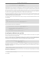
For specific solids, the G4PhysicalVolumeModel that provides the solids also provides, via PreAddSolid, a
pointer to its vis attributes. If the vis attribites pointer in the logical volume is zero, it provides a pointer to
the default vis attributes in the model, which in turn is (currently) provided by the viewer's vis attributes (see
G4VSceneHandler::CreateModelingParameters). So the vis attributes pointer is guaranteed to be pertinent.
If the concrete driver does not implement AddSolid for any particular solid, the base class converts it to primitives
(usually a G4Polyhedron) and again, the vis attributes pointer is guaranteed.
2.12.6.1.4. Drawing style
The drawing style is normally determined by the view parameters but for individual drawable objects it may be overridden by the forced drawing style flags in the vis attributes. A utility function
G4ViewParameters::DrawingStyle G4VSceneHandler::GetDrawingStyle is provided:
G4ViewParameters::DrawingStyle drawing_style = GetDrawingStyle(pVisAtts);
2.12.6.1.5. Auxiliary edges
Similarly, the visibility of auxiliary/soft edges is normally determined by the view parameters but may
be overridden by the forced auxiliary edge visible flag in the vis attributes. Again, a utility function
G4VSceneHandler::GetAuxEdgeVisible is provided:
G4bool isAuxEdgeVisible = GetAuxEdgeVisible (pVisAtts);
2.12.6.1.6. LineSegmentsPerCircle
Also, the precision of rendering curved edges in the polyhedral representation of volumes is normally determined by the view parameters but may be overridden by a forced attribute. A utility function that respects this,
G4VSceneHandler::GetNoOfSides, is provided. For example:
G4Polyhedron::SetNumberOfRotationSteps (GetNoOfSides (pVisAttribs));
2.12.6.1.7. Marker size
These have nothing to do with vis attributes; they are an extra property of markers, i.e., objects that inherit
G4VMarker (circles, squares, text, etc.). However, the algorithm for the actual size is quite complicated and a
utility function G4VSceneHandler::GetMarkerSize is provided:
MarkerSizeType sizeType;
G4double size = GetMarkerSize (text, sizeType);
sizeType is world or screen, signifying that the size is in world coordinates or screen coordinates respectively.
[Status of this chapter]
27.06.05 partially re-organized and section on design philosophy added (from Geant4 general paper) by D.H.
Wright
13.10.05 Section on vis attributes added by John Allison.
25
Design and Function
of Geant4 Categories
06.01.06 Re-write of ‘‘Design Philosphy'' and introduction of ‘‘The Graphics Interfaces'' and ‘‘The Geant4 Visualisation System'' by John Allison.
Dec. 2006 Conversion from latex to Docbook verson by K. Amako
2.13. Intercoms
2.13.1. Design Philosophy
The intercoms category implements an expandable command interpreter which is the key mechanism in Geant4
for realizing customizable and state-dependent user interactions with all categories without being perturbed by the
dependencies among classes. The capturing of commands is handled by a C++ abstract class G4UIsession. Various
concrete implementations of the command capturer are contained in the [user] interfaces category. Taking into
account the rapid evolution of graphical user interface (GUI) technology and consequent dependence on external
facilities, plural and extensible GUIs are offered.
Programmers need only know how to register the commands and parameters appropriate to their problem domain;
no knowledge of GUI programming is required to allow an application to use them through one of the available
GUIs.
The intercoms category also provides the virtual base classes
•
•
•
G4VVisManager,
G4VGraphicsScene, and
G4VGlobalFastSimulationManager.
2.13.2. Class Design
•
•
•
•
•
G4UISession G4UIBatch G4UICommand G4UIparameter G4UImessenger -
The object-oriented design of the 'user interface' related classes is shown in the class diagram Figure 2.21. The
diagram is described in the Booch notation.
Figure 2.21. Overview of intercom classes
[Status of this chapter]
27.06.05 design philosophy (from Geant4 general paper) and class design sections added by D.H. Wright
26
Design and Function
of Geant4 Categories
Dec. 2006 Conversion from latex to Docbook verson by K. Amako
27
Chapter 3. Extending Toolkit Functionality
3.1. Geometry
3.1.1. What can be extended ?
Geant4 already allows a user to describe any desired solid, and to use it in a detector description, in some cases,
however, the user may want or need to extend Geant4's geometry. One reason can be that some methods and types
in the geometry are general and the user can utilise specialised knowledge about his or her geometry to gain a
speedup. The most evident case where this can happen is when a particular type of solid is a key element for a
specific detector geometry and an investment in improving its runtime performance may be worthwhile.
To extend the functionality of the Geometry in this way, a toolkit developer must write a small number of methods
for the new solid. We will document below these methods and their specifications. Note that the implementation
details for some methods are not a trivial matter: these methods must provide the functionality of finding whether
a point is inside a solid, finding the intersection of a line with it, and finding the distance to the solid along any
direction. However once the solid class has been created with all its specifications fulfilled, it can be used like any
Geant4 solid, as it implements the abstract interface of G4VSolid.
Other additions can also potentially be achieved. For example, an advanced user could add a new way of creating
physical volumes. However, because each type of volume has a corresponding navigator helper, this would require
to create a new Navigator as well. To do this the user would have to inherit from G4Navigator and modify the
new Navigator to handle this type of volumes. This can certainly be done, but will probably be made easier to
achieve in the future versions of the Geant4 toolkit.
3.1.2. Adding a new type of Solid
We list below the required methods for integrating a new type of solid in Geant4. Note that Geant4's specifications for a solid pay significant attention to what happens at points that are within a small distance (tolerance,
kCarTolerance in the code) of the surface. So special care must be taken to handle these cases in considering all
different possible scenarios, in order to respect the specifications and allow the solid to be used correctly by the
other components of the geometry module.
Creating a derived class of G4VSolid
The solid must inherit from G4VSolid or one of its derived classes and implement its virtual functions.
Mandatory member functions you must define are the following pure virtual of G4VSolid:
EInside Inside(const G4ThreeVector& p)
G4double DistanceToIn(const G4ThreeVector& p)
G4double DistanceToIn(const G4ThreeVector& p, const G4ThreeVector& v)
G4ThreeVector SurfaceNormal(const G4ThreeVector& p)
G4double DistanceToOut(const G4ThreeVector& p)
G4double DistanceToOut(const G4ThreeVector& p, const G4ThreeVector& v,
const G4bool calcNorm=false,
G4bool *validNorm=0, G4ThreeVector *n)
G4bool CalculateExtent(const EAxis pAxis,
const G4VoxelLimits& pVoxelLimit,
const G4AffineTransform& pTransform,
G4double& pMin,
G4double& pMax) const
G4GeometryType GetEntityType() const
std::ostream& StreamInfo(std::ostream& os) const
They must perform the following functions
EInside Inside(const G4ThreeVector& p)
This method must return:
28
Extending Toolkit Functionality
•
•
•
kOutside if the point at offset p is outside the shape boundaries plus Tolerance/2,
kSurface if the point is <= Tolerance/2 from a surface, or
kInside otherwise.
G4ThreeVector SurfaceNormal(const G4ThreeVector& p)
Return the outwards pointing unit normal of the shape for the surface closest to the point at offset p.
G4double DistanceToIn(const G4ThreeVector& p)
Calculate distance to nearest surface of shape from an outside point p. The distance can be an underestimate.
G4double DistanceToIn(const G4ThreeVector& p, const G4ThreeVector& v)
Return the distance along the normalised vector v to the shape, from the point at offset p. If there is no intersection,
return kInfinity. The first intersection resulting from ‘leaving' a surface/volume is discarded. Hence, this is tolerant
of points on surface of shape.
G4double DistanceToOut(const G4ThreeVector& p)
Calculate distance to nearest surface of shape from an inside point. The distance can be an underestimate.
G4double DistanceToOut(const G4ThreeVector& p, const G4ThreeVector& v,
const G4bool calcNorm=false,
G4bool *validNorm=0, G4ThreeVector *n=0);
Return distance along the normalised vector v to the shape, from a point at an offset p inside or on the surface of
the shape. Intersections with surfaces, when the point is not greater than kCarTolerance/2 from a surface, must
be ignored.
If calcNorm is true, then it must also set validNorm to either
•
•
If calcNorm is false, then validNorm and n are unused.
G4bool CalculateExtent(const EAxis pAxis,
const G4VoxelLimits& pVoxelLimit,
const G4AffineTransform& pTransform,
G4double& pMin,
G4double& pMax) const
Calculate the minimum and maximum extent of the solid, when under the specified transform, and within the
specified limits. If the solid is not intersected by the region, return false, else return true.
G4GeometryType GetEntityType() const;
Provide identification of the class of an object (required for persistency and STEP interface).
std::ostream& StreamInfo(std::ostream& os) const
Should dump the contents of the solid to an output stream.
The method:
G4double GetCubicVolume()
29
Extending Toolkit Functionality
should be implemented for every solid in order to cache the computed value (and therefore reuse it for future calls
to the method) and to eventually implement a precise computation of the solid's volume. If the method will not
be overloaded, the default implementation from the base class will be used (estimation through a Monte Carlo
algorithm) and the computed value will not be stored.
There are a few member functions to be defined for the purpose of visualisation. The first method is mandatory,
and the next four are not.
// Mandatory
virtual void DescribeYourselfTo (G4VGraphicsScene& scene) const = 0;
// Not mandatory
virtual G4VisExtent GetExtent() const;
virtual G4Polyhedron* CreatePolyhedron () const;
virtual G4NURBS*
CreateNURBS
() const;
virtual G4Polyhedron* GetPolyhedron
() const;
What these methods should do and how they should be implemented is described here.
void DescribeYourselfTo (G4VGraphicsScene& scene) const;
This method is required in order to identify the solid to the graphics scene. It is used for the purposes of ‘‘double
dispatch''. All implementations should be similar to the one for G4Box:
void G4Box::DescribeYourselfTo (G4VGraphicsScene& scene) const
{
scene.AddSolid (*this);
}
The method:
G4VisExtent GetExtent() const;
provides extent (bounding box) as a possible hint to the graphics view. You must create it by finding a box that
encloses your solid, and returning a VisExtent that is created from this. The G4VisExtent must presumably be
given the minus x, plus x, minus y, plus y, minus z and plus z extents of this ‘‘box''. For example a cylinder can say
G4VisExtent G4Tubs::GetExtent() const
{
// Define the sides of the box into which the G4Tubs instance would fit.
return G4VisExtent (-fRMax, fRMax, -fRMax, fRMax, -fDz, fDz);
}
The method:
G4Polyhedron* CreatePolyhedron () const;
is required by the visualisation system, in order to create a realistic rendering of your solid. To create a
G4Polyhedron for your solid, consult G4Polyhedron.
While the method:
G4Polyhedron* GetPolyhedron () const;
is a ‘‘smart'' access function that creates on requests a polyhedron and stores it for future access and should be
customised for every solid.
The method:
30
Extending Toolkit Functionality
G4NURBS* CreateNURBS () const;
is not currently utilised, so you do not have to implement it.
3.1.3. Modifying the Navigator
For the vast majority of use-cases, it is not indeed necessary (and definitely not advised) to extend or modify the
existing classes for navigation in the geometry. A possible use-case for which this may apply, is for the description
of a new kind of physical volume to be integrated. We believe that our set of choices for creating physical volumes
is varied enough for nearly all needs. Future extensions of the Geant4 toolkit will probably make easier exchanging
or extending the G4Navigator, by introducing an abstraction level simplifying the customisation. At this time, a
simple abstraction level of the navigator is provided by allowing overloading of the relevant functionalities.
Extending the Navigator
The main responsibilities of the Navigator are:
•
•
locate a point in the tree of the geometrical volumes;
compute the length a particle can travel from a point in a certain direction before encountering a volume
boundary.
The Navigator utilises one helper class for each type of physical volume that exists. You will have to reuse the
helper classes provided in the base Navigator or create new ones for the new type of physical volume.
To extend G4Navigator you will have then to inherit from it and modify these functions in your ModifiedNavigator
to request the answers for your new physical volume type from the new helper class. The ModifiedNavigator
should delegate other cases to the Geant4's standard Navigator.
Replacing the Navigator
Replacing the Navigator is another possible operation. It is similar to extending the Navigator, in that any types
of physical volume that will be allowed must be handled by it. The same functionality is required as described
in the previous section.
However the amount of work is probably potentially larger, if support for all the current types of physical volumes
is required.
The Navigator utilises one helper class for each type of physical volume that exists. These could also potentially
be replaced, allowing a simpler way to create a new navigation system.
3.2. Electromagnetic Fields
3.2.1. Creating a New Type of Field
Geant4 currently handles magnetic and electric fields and, in future releases, will handle combined electromagnetic
fields. Fields due to other forces, not yet included in Geant4, can be provided by describing the new field and
the force it exerts on a particle passing through it. For the time being, all fields must be time-independent. This
restriction may be lifted in the future.
In order to accommodate a new type of field, two classes must be created: a field type and a class that determines
the force. The Geant4 system must then be informed of the new field.
A new Field class
A new type of Field class may be created by inheriting from G4Field
class NewField : public G4Field
{
public:
31
Extending Toolkit Functionality
void
GetFieldValue( const
double Point[3],
double *pField )=0;
}
and deciding how many components your field will have, and what each component represents. For example, three
components are required to describe a vector field while only one component is required to describe a scalar field.
If you want your field to be a combination of different fields, you must choose your convention for which field goes
first, which second etc. For example, to define an electromagnetic field we follow the convention that components
0,1 and 2 refer to the magnetic field and components 3, 4 and 5 refer to the electric field.
By leaving the GetFieldValue method pure virtual, you force those users who want to describe their field to create
a class that implements it for their detector's instance of this field. So documenting what each component means
is required, to give them the necessary information.
For example someone can describe DetectorAbc's field by creating a class DetectorAbcField, that derives from
your NewField
class DetectorAbcField : public NewField
{
public:
void MyFieldGradient::GetFieldValue( const double Point[3],
double *pField );
}
They then implement the function GetFieldValue
void
MyFieldGradient::GetFieldValue( const double Point[3],
double *pField )
{
// We expect pField to point to pField[9];
// This & the order of the components of pField is your own
// convention
// We calculate the value of pField at Point ...
}
A new Equation of Motion for the new Field
Once you have created a new type of field, you must create an Equation of Motion for this Field. This is required
in order to obtain the force that a particle feels.
To do this you must inherit from G4Mag_EqRhs and create your own equation of motion that understands your
field. In it you must implement the virtual function EvaluateRhsGivenB. Given the value of the field, this function
calculates the value of the generalised force. This is the only function that a subclass must define.
virtual void EvaluateRhsGivenB( const G4double y[],
const G4double B[3],
G4double dydx[] ) const = 0;
In particular, the derivative vector dydx is a vector with six components. The first three are the derivative of
the position with respect to the curve length. Thus they should set equal to the normalised velocity, which is
components 3, 4 and 5 of y.
(dydx[0], dydx[1], dydx[2]) = (y[3], y[4], y[5])
The next three components are the derivatives of the velocity vector with respect to the path length. So you should
write the "force" components for
dydx[3], dydx[4] and dydx[5]
for your field.
32
Extending Toolkit Functionality
Get a G4FieldManager to use your field
In order to inform the Geant4 system that you want it to use your field as the global field, you must do the following
steps:
1.
Create a Stepper of your choice:
yourStepper = new G4ClassicalRK( yourEquationOfMotion );
// or if your field is not smooth eg
//
new G4ImplicitEuler( yourEquationOfMotion );
2.
Create a chord finder that uses your Field and Stepper. You must also give it a minimum step size, below
which it does not make sense to attempt to integrate:
yourChordFinder= new G4ChordFinder( yourField,
yourMininumStep, // say 0.01*mm
yourStepper );
3.
Next create a G4FieldManager and give it that chord finder,
yourFieldManager= new G4FieldManager();
yourFieldManager.SetChordFinder(yourChordFinder);
4.
Finally we tell the Geometry that this FieldManager is responsible for creating a field for the detector.
G4TransportationManager::GetTransportationManager()
-> SetFieldManager( yourFieldManager );
Changes for non-electromagnetic fields
If the field you are interested in simulating is not electromagnetic, another minor modification may be required.
The transportation currently chooses whether to propagate a particle in a field or rectilinearly based on whether the
particle is charged or not. If your field affects non-charged particles, you must inherit from the G4Transportation
and re-implement the part of GetAlongStepPhysicalInteractionLength that decides whether the particles is affected
by your force.
In particular the relevant section of code does the following:
// Does the particle have an (EM) field force exerting upon it?
//
if( (particleCharge!=0.0) ){
fieldExertsForce= this->DoesGlobalFieldExist();
// Future: will/can also check whether current volume's field is Zero or
// set by the user (in the logical volume) to be zero.
}
and you want it to ask whether it feels your force. If, for the sake of an example, you wanted to see the effects of
gravity on a heavy hypothetical particle, you could say
// Does the particle have my field's force exerted on it?
//
if (particle->GetName() == "VeryHeavyWIMP") {
fieldExertsForce= this->DoesGlobalFieldExist(); // For gravity
}
After doing all these steps, you will be able to see the effects of your force on a particle's motion.
[Status of this chapter]
10.06.02 partially re-written by D.H. Wright
33
Extending Toolkit Functionality
14.11.02 spell check by P. Arce
3.3. Physics Processes
Adding a new electromagnetic process. Adding a new hadronic process.
[Status of this chapter]
27.06.05 under construction
Dec. 2006 Conversion from latex to Docbook verson by K. Amako
3.4. Hadronic Physics
3.4.1. Introduction
Optimal exploitation of hadronic final states played a key role in successes of all recent collider experiment in
HEP, and the ability to use hadronic final states will continue to be one of the decisive issues during the analysis
phase of the LHC experiments. Monte Carlo programs like Geant4 facilitate the use of hadronic final states, and
have been developed for many years.
We give an overview of the Object Oriented frameworks for hadronic generators in Geant4, and illustrate the
physics models underlying hadronic shower simulation on examples, including the three basic types of modeling;
data-driven, parametrisation-driven, and theory-driven modeling, and their possible realisations in the Object Oriented component system of Geant4. We put particular focus on the level of extendibility that can and has been
achieved by our Russian dolls approach to Object Oriented design, and the role and importance of the frameworks
in a component system.
3.4.2. Principal Considerations
The purpose of this section is to explain the implementation frameworks used in and provided by Geant4 for
hadronic shower simulation as in the 1.1 release of the program. The implementation frameworks follow the Russian dolls approach to implementation framework design. A top-level, very abstracting implementation framework
provides the basic interface to the other Geant4 categories, and fulfils the most general use-case for hadronic shower simulation. It is refined for more specific use-cases by implementing a hierarchy of implementation frameworks,
each level implementing the common logic of a particular use-case package in a concrete implementation of the
interface specification of one framework level above, this way refining the granularity of abstraction and delegation. This defines the Russian dolls architectural pattern. Abstract classes are used as the delegation mechanism 1 .
All framework functional requirements were obtained through use-case analysis. In the following we present for
each framework level the compressed use-cases, requirements, designs including the flexibility provided, and illustrate the framework functionality with examples. All design patterns cited are to be read as defined in [ Gamma1995 ].
3.4.3. Level 1 Framework - processes
There are two principal use-cases of the level 1 framework. A user will want to choose the processes used for his
particular simulation run, and a physicist will want to write code for processes of his own and use these together
with the rest of the system in a seamless manner.
Requirements
1.
2.
Provide a standard interface to be used by process implementations.
Provide registration mechanisms for processes.
1
The same can be achieved with template specialisations with slightly improved CPU performance but at the cost of significantly more
complex designs and, with present compilers, significantly reduced portability.
34
Extending Toolkit Functionality
Design and interfaces
Both requirements are implemented in a sub-set of the tracking-physics interface in Geant4}. The class diagram
is shown in Figure 3.1.
Figure 3.1. Level 1 implementation framework of the hadronic category of GEANT4.
All processes have a common base-class G4VProcess, from which a set of specialised classes are derived. Three
of them are used as base classes for hadronic processes for particles at rest (G4VRestProcess), for interactions
in flight (G4VDiscreteProcess), and for processes like radioactive decay where the same implementation
can represent both these extreme cases (G4VRestDiscrete-Process).
Each of these classes declares two types of methods; one for calculating the time to interaction or the physical
interaction length, allowing tracking to request the information necessary to decide on the process responsible
for final state production, and one to compute the final state. These are pure virtual methods, and have to be
implemented in each individual derived class, as enforced by the compiler.
Framework functionality
The functionality provided is through the use of process base-class pointers in the tracking-physics interface, and
the G4Process-Manager. All functionality is implemented in abstract, and registration of derived process
classes with the G4Process-Manager of an individual particle allows for arbitrary combination of both Geant4
provided processes, and user-implemented processes. This registration mechanism is a modification on a Chain
of Responsibility. It is outside the scope of the current paper, and its description is available from G4Manual.
3.4.4. Level 2 Framework - Cross Sections and Models
At the next level of abstraction, only processes that occur for particles in flight are considered. For these, it is easily
observed that the sources of cross sections and final state production are rarely the same. Also, different sources
will come with different restrictions. The principal use-cases of the framework are addressing these commonalities.
A user might want to combine different cross sections and final state or isotope production models as provided
by Geant4, and a physicist might want to implement his own model for particular situation, and add cross-section
data sets that are relevant for his particular analysis to the system in a seamless manner.
Requirements
1.
2.
Flexible choice of inclusive scattering cross-sections.
Ability to use different data-sets for different parts of the simulation, depending on the conditions at the point
of interaction.
35
Extending Toolkit Functionality
3.
4.
5.
6.
7.
8.
9.
Ability to add user-defined data-sets in a seamless manner.
Flexible, unconstrained choice of final state production models.
Ability to use different final state production codes for different parts of the simulation, depending on the
conditions at the point of interaction.
Ability to add user-defined final state production models in a seamless manner.
Flexible choice of isotope production models, to run in parasitic mode to any kind of transport models.
Ability to use different isotope production codes for different parts of the simulation, depending on the conditions at the point of interaction.
Ability to add user-defined isotope production models in a seamless manner.
Design and interfaces
The above requirements are implemented in three framework components, one for cross-sections, final state production, and isotope production each. The class diagrams are shown in Figure 3.2 for the cross-section aspects,
Figure 3.3 for the final state production aspects, and figure Figure 3.4 for the isotope production aspects.
Figure 3.2. Level 2 implementation framework of the
hadronic category of Geant4; cross-section aspect.
Figure 3.3. Level 2 implementation framework of the
hadronic category of Geant4; final state production aspect.
36
Extending Toolkit Functionality
Figure 3.4. Level 2 implementation framework of the
hadronic category of Geant4; isotope production aspect
The three parts are integrated in the G4Hadronic-Process class, that serves as base-class for all hadronic
processes of particles in flight.
Cross-sections
Each hadronic process is derived from G4Hadronic-Process}, which holds a list of ‘‘cross section data sets''. The term ‘‘data set'' is representing an object that encapsulates methods and data for calculating total
cross sections for a given process in a certain range of validity. The implementations may take any form. It
can be a simple equation as well as sophisticated parameterisations, or evaluated data. All cross section data
set classes are derived from the abstract class G4VCrossSection-DataSet}, which declares methods that
allow the process inquire, about the applicability of an individual data-set through IsApplicable(const
G4DynamicParticle*, const G4Element*), and to delegate the calculation of the actual cross-section
value through GetCrossSection(const G4DynamicParticle*, const G4Element*).
Final state production
The G4HadronicInteraction base class is provided for final state generation. It declares a minimal interface of only one pure virtual method: G4VParticleChange* ApplyYourself(const G4Track &,
G4Nucleus &)}. G4HadronicProcess provides a registry for final state production models inheriting
from G4Hadronic-Interaction. Again, final state production model is meant in very general terms. This
can be an implementation of a quark gluon string model [QGSM], a sampling code for ENDF/B data formats [
ENDFForm ], or a parametrisation describing only neutron elastic scattering off Silicon up to 300~MeV.
Isotope production
For isotope production, a base class (G4VIsotope-Production) is provided. It declares a method
G4IsoResult * GetIsotope(const G4Track &, const G4Nucleus &) that calculates and
returns the isotope production information. Any concrete isotope production model will inherit from this class,
and implement the method. Again, the modeling possibilities are not limited, and the implementation of concrete
production models is not restricted in any way. By convention, the GetIsotope method returns NULL, if the
model is not applicable for the current projectile target combination.
Framework functionality:
Cross Sections
G4HadronicProcess provides registering possibilities for data sets. A default is provided covering all possible
conditions to some approximation. The process stores and retrieves the data sets through a data store that acts
like a FILO stack (a Chain of Responsibility with a First In Last Out decision strategy). This allows the user to
37
Extending Toolkit Functionality
map out the entire parameter space by overlaying cross section data sets to optimise the overall result. Examples
are the cross sections for low energy neutron transport. If these are registered last by the user, they will be used
whenever low energy neutrons are encountered. In all other conditions the system falls back on the default, or
data sets with earlier registration dates. The fact that the registration is done through abstract base classes with
no side-effects allows the user to implement and use his own cross sections. Examples are special reaction cross
sections of #0-nuclear interactions that might be used for #/#' analysis at LHC to control the systematic error.
Final state production
The G4HadronicProcess class provides a registration service for classes deriving from G4Hadronic-Interaction, and delegates final state production to the applicable model. G4Hadronic-Interactionprovides the functionality needed to define and enforce the applicability of a particular model. Models inheriting from
G4Hadronic-Interaction can be restricted in applicability in projectile type and energy, and can be activated/deactivated for individual materials and elements. This allows a user to use final state production models in
arbitrary combinations, and to write his own models for final state production. The design is a variant of a Chain of
Responsibility. An example would be the likely CMS scenario - the combination of low energy neutron transport
with a quantum molecular dynamics [QMD], invariant phase space decay [CHIPS], and fast parametrised models
for calorimeter materials, with user defined modeling of interactions of spallation nucleons with the most abundant
tracker and calorimeter materials.
Isotope production
The G4HadronicProcess by default calculates the isotope production information from the final state given by the transport model. In addition, it provides a registering mechanism for isotope production models that
run in parasitic mode to the transport models and inherit from G4VIsotope-Production. The registering
mechanism behaves like a FILO stack, again based on Chain of Responsibility. The models will be asked for
isotope production information in inverse order of registration. The first model that returns a non-NULL value
will be applied. In addition, the G4Hadronic-Process provides the basic infrastructure for accessing and
steering of isotope-production information. It allows to enable and disable the calculation of isotope production
information globally, or for individual processes, and to retrieve the isotope production information through the
G4IsoParticleChange * GetIsotopeProductionInfo()} method at the end of each step. The
G4HadronicProcess is a finite state machine that will ensure the GetIsotope-ProductionInfo returns a non-zero value only at the first call after isotope production occurred. An example of the use of this functionality is the study of activation of a Germanium detector in a high precision, low background experiment.
3.4.5. Level 3 Framework - Theoretical Models
Figure 3.5. Level 3 implementation framework of the
hadronic category of Geant4; theoretical model aspect.
Geant4 provides at present one implementation framework for theory driven models. The main use-case is that of
a user wishing to use theoretical models in general, and to use various intra-nuclear transport or pre-compound
models together with models simulating the initial interactions at very high energies.
Requirements
1.
Allow to use or adapt any string-parton or parton transport [VNI],
38
Extending Toolkit Functionality
2.
3.
4.
5.
6.
7.
8.
Allow to adapt event generators, ex. [PYTHIA7], state production in shower simulation.
Allow for combination of the above with any intra-nuclear transport (INT).
Allow stand-alone use of intra-nuclear transport.
Allow for combination of the above with any pre-compound model.
Allow stand-alone use of any pre-compound model.
Allow for use of any evaporation code.
Allow for seamless integration of user defined components for any of the above.
Design and interfaces
To provide the above flexibility, the following abstract base classes have been implemented:
•
•
•
•
G4VHighEnergyGenerator
G4VIntranuclearTransportModel
G4VPreCompoundModel
G4VExcitationHandler
In addition, the class G4TheoFS-Generator is provided to orchestrate interactions between these classes. The
class diagram is shown in Figure 3.5.
G4VHighEnergy-Generator serves as base class for parton transport or parton string models, and for
Adapters to event generators. This class declares two methods, Scatter, and GetWoundedNucleus.
The base class for INT inherits from G4Hadronic-Interaction, making any concrete implementation usable as a stand-alone model. In doing so, it re-declares the ApplyYourself interface of G4Hadronic-Interaction, and adds a second interface, Propagate, for further propagation after high energy interactions.
Propagate takes as arguments a three-dimensional model of a wounded nucleus, and a set of secondaries with
energies and positions.
The base class for pre-equilibrium decay models, G4VPre-CompoundModel, inherits from G4HadronicInteraction, again making any concrete implementation usable as stand-alone model. It adds a pure virtual
DeExcite method for further evolution of the system when intra-nuclear transport assumptions break down.
DeExcite takes a G4Fragment, the Geant4 representation of an excited nucleus, as argument.
The base class for evaporation phases, G4VExcitation-Handler, declares an abstract method, BreakItUP(), for compound decay.
Framework functionality
The G4TheoFSGenerator class inherits from G4Hadronic-Interaction, and hence can be registered as a model for final state production with a hadronic process. It allows a concrete implementation of
G4VIntranuclear-TransportModel and G4VHighEnergy-Generator to be registered, and delegates initial interactions, and intra-nuclear transport of the corresponding secondaries to the respective classes.
The design is a complex variant of a Strategy. The most spectacular application of this pattern is the use of partonstring models for string excitation, quark molecular dynamics for correlated string decay, and quantum molecular
dynamics for transport, a combination which promises to result in a coherent description of quark gluon plasma
in high energy nucleus-nucleus interactions.
The class G4VIntranuclearTransportModel provides registering mechanisms for concrete implementations of G4VPreCompound-Model, and provides concrete intra-nuclear transports with the possibility of delegating pre-compound decay to these models.
G4VPreCompoundModel provides a registering mechanism for compound decay through the
G4VExcitation-Handler interface, and provides concrete implementations with the possibility of delegating the decay of a compound nucleus.
The concrete scenario of G4TheoFS-Generator using a dual parton model and a classical cascade, which
in turn uses an exciton pre-compound model that delegates to an evaporation phase, would be the following:
G4TheoFS-Generator receives the conditions of the interaction; a primary particle and a nucleus. It asks the
39
Extending Toolkit Functionality
dual parton model to perform the initial scatterings, and return the final state, along with the by then damaged
nucleus. The nucleus records all information on the damage sustained. G4TheoFS-Generator forwards all
information to the classical cascade, that propagates the particles in the already damaged nucleus, keeping track of
interactions, further damage to the nucleus, etc.. Once the cascade assumptions break down, the cascade will collect
the information of the current state of the hadronic system, like excitation energy and number of excited particles,
and interpret it as a pre-compound system. It delegates the decay of this to the exciton model. The exciton model
will take the information provided, and calculate transitions and emissions, until the number of excitons in the
system equals the mean number of excitons expected in equilibrium for the current excitation energy. Then it hands
over to the evaporation phase. The evaporation phase decays the residual nucleus, and the Chain of Command rolls
back to G4TheoFS-Generator, accumulating the information produced in the various levels of delegation.
3.4.6. Level 4 Frameworks - String Parton Models and IntraNuclear Cascade
Figure 3.6. Level 4 implementation framework of the
hadronic category of Geant4; parton string aspect.
Figure 3.7. Level 4 implementation framework of the
hadronic category of Geant4; intra-nuclear transport aspect.
The use-cases of this level are related to commonalities and detailed choices in string-parton models and cascade
models. They are use-cases of an expert user wishing to alter details of a model, or a theoretical physicist, wishing
to study details of a particular model.
Requirements
1.
2.
3.
4.
Allow to select string decay algorithm
Allow to select string excitation.
Allow the selection of concrete implementations of three-dimensional models of the nucleus
Allow the selection of concrete implementations of final state and cross sections in intra-nuclear scattering.
40
Extending Toolkit Functionality
Design and interfaces
To fulfil the requirements on string models, two abstract classes are provided, the G4VParton-StringModel and the G4VString-Fragmentation. The base class for parton string models, G4VParton-StringModel, declares the GetStrings() pure virtual method. G4VString-Fragmentation, the pure abstract
base class for string fragmentation, declares the interface for string fragmentation.
To fulfill the requirements on intra-nuclear transport, two abstract classes are provided, G4V3DNucleus, and
G4VScatterer. At this point in time, the usage of these intra-nuclear transport related classes by concrete codes
is not enforced by designs, as the details of the cascade loop are still model dependent, and more experience has to
be gathered to achieve standardisation. It is within the responsibility of the implementers of concrete intra-nuclear
transport codes to use the abstract interfaces as defined in these classes.
The class diagram is shown in Figure 3.6 for the string parton model aspects, and in Figure 3.7 for the intra-nuclear
transport.
Framework functionality
Again variants of Strategy, Bridge and Chain of Responsibility are used. G4VParton-StringModel implements the initialisation of a three-dimensional model of a nucleus, and the logic of scattering. It delegates secondary
production to string fragmentation through a G4VString-Fragmentation pointer. It provides a registering
service for the concrete string fragmentation, and delegates the string excitation to derived classes. Selection of
string excitation is through selection of derived class. Selection of string fragmentation is through registration.
3.4.7. Level 5 Framework - String De-excitation}
Figure 3.8. Level 5 implementation framework of the
hadronic category of Geant4; string fragmentation aspect.
The use-case of this level is that of a user or theoretical physicist wishing to understand the systematic effects
involved in combining various fragmentation functions with individual types of string fragmentation. Note that this
framework level is meeting the current state of the art, making extensions and changes of interfaces in subsequent
releases likely.
Requirements
1.
Allow the selection of fragmentation function.
Design and interfaces
A base class for fragmentation functions, G4VFragmentation-Function}, is provided. It declares the GetLightConeZ() interface.
41
Extending Toolkit Functionality
Framework functionality
The design is a basic Strategy. The class diagram is shown in Figure 3.8. At this point in time, the usage of
the G4VFragmentation-Function is not enforced by design, but made available from the G4VStringFragmentation to an implementer of a concrete string decay. G4VString-Fragmentation provides a
registering mechanism for the concrete fragmentation function. It delegates the calculation of zf of the hadron to
split of the string to the concrete implementation. Standardisation in this area is expected.
3.5. Visualisation
This Chapter is intended to be read after Chapter Section 2.12 on Visualisation object oriented design in Part II.
Many of the concepts used here are defined there, and it strongly recommended that a writer of a new visualisation
driver or trajectory drawer reads Chapter Section 2.12 first. The class structure described there is summarised in
Figure 3.9.
Figure 3.9. Geant Visualisation System Class Diagram
3.5.1. Creating a new graphics driver
To create a new graphics driver for Geant4, it is necessary to implement a new set of three classes derived from
the three base classes, G4VGraphicsSystem, G4VSceneHandler and G4VViewer.
3.5.1.1. A useful place to start
A skeleton set of classes is included in the code distribution in the visualisation category under subdirectory
visualisation/XXX (but they are not default-registered graphics systems 2
There are several sets of classes, described in more detail below. A recommended approach is to copy the files
that best match your graphics system to a new subdirectory with a name that suits your graphics system .
Then
1.
2.
3.
4.
5.
6.
Change the name of the files (change the code -- XXX or XXXFile, etc., as chosen -- to something that suits
your graphics system ).
Change XXX similarly in all files.
Change XXX similarly in name := G4XXX in GNUmakefile.
Add your new subdirectory to SUBDIRS and SUBLIBS in visualisation/GNUmakefile.
Look at the code and use it to build your visualisation driver. You might also find it useful to look at ASCIITree (and VTree) as an example of a minimal graphics driver . Look at FukuiRenderer as an example
of a driver which implements AddSolid methods for some solids. Look at OpenGL as an example of a
driver which implements a graphical database (display lists) and the machinery to decide when to rebuild.
(OpenGL is complicated by the proliferation of combinations of the use or not of display lists for three window systems, X-windows, X with motif (interactive), Microsoft Windows (Win32), a total of six combinations, and much use is made of inheritance to avoid code duplication.)
If it requires external libraries, introduce two new environment variables G4VIS_BUILD_XXX_DRIVER
and G4VIS_USE_XXX (where XXX is your choice as above) and make the modifications to:
2
To do this,simply instantiate and register, for example: visManager->RegisterGraphicsSystem(new G4XXX) before visManager->Initialise().
42
Extending Toolkit Functionality
•
•
•
source/visualization/management/include/G4VisExecutive.icc
config/G4VIS_BUILD.gmk
config/G4VIS_USE.gmk
3.5.1.1.1. Graphics driver templates in the XXX sub-category
You may use the following templates to help you get started writing a graphics driver . (The word ‘‘template'' is
used in the ordinary sense of the word; they are not C++ templates.)
•
•
•
•
G4XXX, G4XXXSceneHandler, G4XXXViewer Templates for the simplest possible graphics driver .
These would be suitable for an ‘‘immediate'' driver, i.e., one which renders each object immediately to a screen.
Of course, if the view needs re-drawing, as, for example, after a change of viewpoint, the viewer requests a
re-issue of drawn objects.
G4XXXFile, G4XXXFileSceneHandler, G4XXXFileViewer Templates for a file-writing graphics
driver. The particular features are: delayed opening of the file on receipt of the first item; rewinding file on
ClearView (to simulate the clearing of views and prevent the duplication of material in the file); closing of the
file on ShowView, which may also trigger the launch of a browser. There are various degrees of sophistication
in, for example, the allocation of filenames -- see FukuiRenderer or HepRepFile.
These templates also show the use of a specific AddSolid function whereby the specific parameters, for
example, the dimensions of a G4Box, can be accessed.
G4XXXStored, G4XXXStoredSceneHandler, G4XXXStoredViewer Templates for a graphics
driver with a store/database. The advantage of a store is that the view can be refreshed, for example, from
a different viewpoint, without a need to recompute. It is up to the viewer to decide when a re-computation
is necessary. They also show how to distinguish between permanent and transient objects -- see also Section
Section 3.5.1.6.
G4XXXSG, G4XXXSGSceneHandler, G4XXXSGViewer Templates for a sophisticated graphics driver
with a scene graph. The scene graph, following Open Inventor parlance, is a tree of objects that dictates the
order in which the objects are rendered. It obviously lends itself to the rendering of the Geant4 geometry
hierarchy. For example, the Open Inventor driver draws only the top level volumes unless made invisible by
picking. Thus the user can unwrap a branch of the geometry level by level. This has performance benefits and
gives the user significant and useful control over the view. These classes show how to make a scene graph of
drawn volumes, i.e., the set of volumes that have not been culled. (Normally, volumes marked invisible are
culled, i.e., not drawn. Also, the user may wish to limit the number of drawn volumes for performance reasons.)
The drivers also have to process non-geometry items and distinguish between transient and permanent objects
as above.
3.5.1.2. Important Command Actions
To help understand how the Geant4 Visualization System works, here are a few important function invocation
sequences that follow user commands. For an explanation of the commands themselves, see command guidance or
the Control section of the Application Developers Guide. For a fuller explanation of the functions, see appropriate
base class head files or Software Reference Manual.
•
/vis/viewer/clear
viewer->ClearView();
viewer->FinishView();
•
// Clears buffer or rewinds file.
// Swaps buffer (double buffer systems).
/vis/viewer/flush
/vis/viewer/refresh
/vis/viewer/update
•
/vis/viewer/rebuild
viewer->SetNeedKernelVisit(true);
43
Extending Toolkit Functionality
•
/vis/viewer/refresh If the view is ‘‘auto-refresh'', this command is also invoked after /vis/viewer/create, /vis/viewer/rebuild or a change of view parameters (/vis/viewer/set/..., etc.).
viewer->SetView();
viewer->ClearView();
viewer->DrawView();
•
Sets camera position, etc.
Clears buffer or rewinds file.
Draws to screen or writes to
file/socket.
/vis/viewer/update
viewer->ShowView();
•
//
//
//
//
// Activates interactive windows or
// closes file and/or triggers
// post-processing.
/vis/scene/notifyHandlers For each viewer of the current scene, the equivalent of
/vis/viewer/refresh
If ‘‘flush'' is specified on the command line, the equivalent of
/vis/viewer/update
/vis/scene/notifyHandlers is also invoked after a change of scene (/vis/scene/add/..., etc.).
3.5.1.3. What happens in DrawView?
This depends on the viewer. Those with their own graphical database, for example, OpenGL's display lists or Open
Inventor's scene graph, do not need to re-traverse the scene unless there has been a significant change of view
parameters. For example, a mere change of viewpoint requires only a change of model-view matrix whilst a change
of rendering mode from wireframe to surface might require a rebuild of the graphical database. A rebuild of the
run-duration (persistent) objects in the scene is called a ‘‘kernel visit''; the viewer prints ‘‘Traversing scene data...''.
Note that end-of-event (transient) objects are only rebuilt at the end of an event or run, under control of the visualisation manager. Smart scene handlers keep them in separate display lists so that they can be rebuilt separately
from the run-duration objects - see Section 3.5.1.6.
•
Integrated
viewers
with
no
graphical
G4OpenGLImmediateXViewer::DrawView().
NeedKernelVisit();
ProcessView();
FinishView();
•
database
example,
// Always need to visit G4 kernel.
Integrated
viewers
with
graphical
G4OpenGLStoredXViewer::DrawView().
database
KernelVisitDecision(); // Private function containing...
if significant change of view parameters...
NeedKernelVisit();
ProcessView();
FinishView();
•
For
File-writing viewers For example, G4DAWNFILEViewer::DrawView().
NeedKernelVisit();
ProcessView();
Note that viewers needing to invoke FinishView must do it in DrawView.
44
For
example,
Extending Toolkit Functionality
3.5.1.4. What happens in ProcessView?
ProcessView is inherited from G4VViewer:
void
//
//
//
//
//
if
G4VViewer::ProcessView() {
If ClearStore has been requested, e.g., if the scene has changed,
of if the concrete viewer has decided that it necessary to visit
the kernel, perhaps because the view parameters have changed
drastically (this should be done in the concrete viewer's
DrawView)...
(fNeedKernelVisit) {
fSceneHandler.ProcessScene(*this);
fNeedKernelVisit = false;
}
}
3.5.1.5. What happens in ProcessScene?
ProcessScene is inherited from G4VSceneHandler}. It causes a traversal of the run-duration models in the
scene. For drivers with graphical databases, it causes a rebuild (ClearStore). Then for the run-duration models:
fReadyForTransients = false;
BeginModeling();
for each run-duration model...
pModel -> DescribeYourselfTo(*this);
EndModeling();
fReadyForTransients = true;
(A second pass is made on request -- see G4VSceneHandler::ProcessScene.) The use of fReadyForTransients is described in Section 3.5.1.6.
What happens then depends on the type of model:
•
G4AxesModel G4AxesModel::DescribeYourselfTo simply calls sceneHandler.AddPrimitive
methods directly.
sceneHandler.BeginPrimitives();
sceneHandler.AddPrimitive(x_axis);
sceneHandler.EndPrimitives();
•
// etc.
Most other models are like this, except for the following...
G4PhysicalVolumeModel The geometry is descended recursively, culling policy is enacted, and for each
accepted (and possibly, clipped) solid:
sceneHandler.PreAddSolid(theAT, *pVisAttribs);
pSol->DescribeYourselfTo(sceneHandler);
// For example, if pSol points to a G4Box...
|-->G4Box::DescribeYourselfTo(G4VGraphicsScene& scene){
scene.AddSolid(*this);
}
sceneHandler.PostAddSolid();
The scene handler may implement the virtual function { AddSolid(const G4Box&)}, or inherit:
void G4VSceneHandler::AddSolid(const G4Box& box) {
RequestPrimitives(box);
}
RequestPrimitives converts the solid into primitives (G4Polyhedron) and invokes AddPrimitive:
45
Extending Toolkit Functionality
BeginPrimitives(*fpObjectTransformation);
pPolyhedron = solid.GetPolyhedron();
AddPrimitive(*pPolyhedron);
EndPrimitives();
The resulting default sequence for a G4PhysicalVolumeModel is shown in Figure 3.10.
DrawView();
|-->ProcessView();
|-->ProcessScene();
|-->BeginModeling();
|-->pModel -> DescribeYourselfTo(*this);
|
|-->sceneHandler.PreAddSolid(theAT, *pVisAttribs);
|
|-->pSol->DescribeYourselfTo(sceneHandler);
|
|
|-->sceneHandler.AddSolid(*this);
|
|
|-->RequestPrimitives(solid);
|
|
|-->BeginPrimitives (*fpObjectTransformation);
|
|
|-->pPolyhedron = solid.GetPolyhedron();
|
|
|-->AddPrimitive(*pPolyhedron);
|
|
|-->EndPrimitives();
|
|-->sceneHandler.PostAddSolid();
|-->EndModeling();
Figure 3.10. The default sequence for a G4PhysicalVolumeModel}
Note the sequence of calls at the core:
sceneHandler.PreAddSolid(theAT, *pVisAttribs);
pSol->DescribeYourselfTo(sceneHandler);
|-->sceneHandler.AddSolid(*this);
|-->RequestPrimitives(solid);
|-->BeginPrimitives (*fpObjectTransformation);
|-->pPolyhedron = solid.GetPolyhedron();
|-->AddPrimitive(*pPolyhedron);
|-->EndPrimitives();
sceneHandler.PostAddSolid();
is reduced to
sceneHandler.PreAddSolid(theAT, *pVisAttribs);
pSol->DescribeYourselfTo(sceneHandler);
|-->sceneHandler.AddSolid(*this);
sceneHandler.PostAddSolid();
if the scene handler implements its own AddSolid. Moreover, the sequence
BeginPrimitives (*fpObjectTransformation);
AddPrimitive(*pPolyhedron);
EndPrimitives();
•
can be invoked without a prior PreAddSolid, etc. The flag fProcessingSolid will be false for the last
case. The possibility of any or all of these three scenarios occurring, for both permanent and transient objects,
affects the implementation of a scene handler if there is any attempt to build a graphical database. This is
reflected in the templates XXXStored and XXXSG described in Section 3.5.1.1.1. Transients are discussed
in Section 3.5.1.6.
G4TrajectoriesModel At end of event, the trajectory
container is unpacked and, for each trajectory,
46
sceneHandler.AddCompound called. The scene handler may implement this virtual function or inherit:
Extending Toolkit Functionality
}
Similarly, the user may implement DrawTrajectory or inherit:
void G4VTrajectory::DrawTrajectory(G4int i_mode) const {
G4VVisManager* pVVisManager = G4VVisManager::GetConcreteInstance();
if (0 != pVVisManager) {
pVVisManager->DispatchToModel(*this, i_mode);
}
}
Thence, the Draw method of the current trajectory model is invoked (see Section 3.5.2 for details on trajectory
models), which in turn, invokes Draw methods of the visualisation manager. The resulting default sequence
for a G4TrajectoriesModel is shown in Figure 3.11.
DrawView();
|-->ProcessView();
|-->ProcessScene();
|-->BeginModeling();
|-->pModel -> DescribeYourselfTo(*this);
|
|-->AddCompound(trajectory);
|
|-->trajectory.DrawTrajectory(...);
|
|-->DispatchToModel(...);
|
|-->model->Draw(...);
|
|-->G4VisManager::Draw(...);
|
|-->BeginPrimitives(objectTransform);
|
|-->AddPrimitive(...);
|
|-->EndPrimitives();
|-->EndModeling();
Figure 3.11. The default sequence for a G4PhysicalVolumeModel}
3.5.1.6. Dealing with transient objects
Any visualisable object not defined in the run-duration part of a scene is treated as ‘‘transient''. This includes
trajectories, hits or anything drawn by the user through the G4VVisManager user-level interface (unless as
part of a run-duration model implementation). A flag, fReadyForTransients}, is maintained by the scene
handler. In fact, its normal state is true, and only temporarily, during handling of the run-duration part of the
scene, is it set to false -- see description of ProcessScene, Section 3.5.1.5.
If the driver supports a graphical database, it is smart to distinguish transient and permanent objects. In this case,
every Add method of the scene handler must be transient-aware. In some cases, it is enough to open a graphical data base component in BeginPrimitives, fill it in AddPrimitive and close it appropriately in EndPrimitives. In others, initialisation is done in BeginModeling and consolidation in EndModeling -- see
G4OpenGLStoredSceneHandler. If any AddSolid method is implemented, then the graphical data base
component should be opened in PreAddSolid, protecting against double opening, for example,
void G4XXXStoredSceneHandler::BeginPrimitives
(const G4Transform3D& objectTransformation) {
G4VSceneHandler::BeginPrimitives(objectTransformation);
// If thread of control has already passed through PreAddSolid,
// avoid opening a graphical data base component again.
if (!fProcessingSolid) {
for other solids.
The reason for this distinction is that at end of run the user typically wants to display trajectories on a view of the
detector, then, at the end of the next event 3 , erase the old and see new trajectories. The visualisation manager
messages the scene handler with ClearTransientStore just before drawing the trajectories to achieve this.
3
There is an option to accumulate trajectories across events and runs -- see commands /vis/scene/endOfEventAction and /vis/
scene/endOfRunAction.
47
Extending Toolkit Functionality
If the driver does not have a graphical database or does not distinguish between transient and persistent objects, it
must emulate ClearTransientStore. Typically, it must erase everything, including the detector, and re-draw
the detector and other run-duration objects, ready for the transients to be added. File-writing drivers must rewind
the output file. Typically:
void G4HepRepFileSceneHandler::ClearTransientStore() {
G4VSceneHandler::ClearTransientStore();
// This is typically called after an update and before drawing hits
// of the next event. To simulate the clearing of "transients"
// (hits, etc.) the detector is redrawn...
if (fpViewer) {
fpViewer -> SetView();
fpViewer -> ClearView();
fpViewer -> DrawView();
}
}
ClearView rewinds the output file and DrawView re-draws the detector, etc. (For smart drivers, DrawView
is smart enough to know not to redraw the detector, etc., unless the view parameters have changed significantly
-- see Section 3.5.1.3)
3.5.1.7. More about scene models
Scene models conform to the G4VModel abstract interface. Available models are listed and described there in
varying detail. Section 3.5.1.5 describes their use in some common command actions.
In the design of a new model, care should be taken to handle the possibility that the G4ModelingParameters
pointer is zero. Currently the only use of the modeling parameters is to communicate the culling policy. Most
models, therefore, have no need for modeling parameters.
3.5.2. Enhanced Trajectory Drawing
3.5.2.1. Creating a new trajectory model
New trajectory models must inherit from G4VTrajectoryModel and implement these pure virtual functions:
virtual void Draw(const G4VTrajectory&, G4int i_mode = 0,
const G4bool& visible = true) const = 0;
virtual void Print(std::ostream& ostr) const = 0;
To use the new model directly in compiled code, simply register it with the G4VisManager, eg:
G4VisManager* visManager = new G4VisExecutive;
visManager->Initialise();
// Create custom model
MyCustomTrajectoryModel* myModel =
new MyCustomTrajectoryModel("custom");
// Configure it if necessary then register with G4VisManager
...
visManager->RegisterModel(myModel);
3.5.2.2. Adding interactive functionality
Additional classes need to be written if the new model is to be created and configured interactively:
•
Messenger classes
Messengers to configure the model should inherit from G4VModelCommand. The concrete trajectory model
type should be used for the template parameter, eg:
48
Extending Toolkit Functionality
class G4MyCustomModelCommand
: public G4VModelCommand<G4TrajectoryDrawByParticleID> {
...
};
•
A number of general use templated commands are available in G4ModelCommandsT.hh.
Factory class
A factory class responsible for the model and associated messenger creation must also be written. The factory
should inherit from G4VModelFactory. The abstract model type should be used for the template parameter, eg:
class G4TrajectoryDrawByChargeFactory
: public G4VModelFactory<G4VTrajectoryModel> {
...
};
The model and associated messengers should be constructed in the Create method. Optionally, a context object
can also be created, with its own associated messengers. For example:
ModelAndMessengers
G4TrajectoryDrawByParticleIDFactory::
Create(const G4String& placement, const G4String& name)
{
// Create default context and model
G4VisTrajContext* context = new G4VisTrajContext("default");
G4TrajectoryDrawByParticleID* model =
new G4TrajectoryDrawByParticleID(name, context);
// Create messengers for default context configuration
AddContextMsgrs(context, messengers, placement+"/"+name);
// Create messengers for drawer
messengers.push_back(new
G4ModelCmdSetStringColour<G4TrajectoryDrawByParticleID>
(model, placement));
messengers.push_back(new
G4ModelCmdSetDefaultColour<G4TrajectoryDrawByParticleID>
(model, placement));
messengers.push_back(new
G4ModelCmdVerbose<G4TrajectoryDrawByParticleID>
(model, placement));
return ModelAndMessengers(model, messengers);
}
The new factory must then be registered with the visualisation manager. This should be done by overriding the
G4VisManager::RegisterModelFactory method in a subclass. See, for example, the G4VisManager implementation:
G4VisExecutive::RegisterModelFactories()
{
...
RegisterModelFactory(new G4TrajectoryDrawByParticleIDFactory());
}
3.5.3. Trajectory Filtering
3.5.3.1. Creating a new trajectory filter model
New trajectory filters must inherit at least from G4VFilter. The models supplied with the Geant4 distribution
inherit from G4SmartFilter, which implements some specialisations on top of G4VFilter. The models implement
these pure virtual functions:
49
Extending Toolkit Functionality
// Evaluate method implemented in subclass
virtual G4bool Evaluate(const T&) = 0;
// Print subclass configuration
virtual void Print(std::ostream& ostr) const = 0;
To use the new filter model directly in compiled code, simply register it with the G4VisManager, eg:
G4VisManager* visManager = new G4VisExecutive;
visManager->Initialise();
// Create custom model
MyCustomTrajectoryFilterModel* myModel =
new MyCustomTrajectoryFilterModel("custom");
// Configure it if necessary then register with G4VisManager
...
visManager->RegisterModel(myModel);
3.5.3.2. Adding interactive functionality
Additional classes need to be written if the new model is to be created and configured interactively. The mechanism
is exactly the same as that used to create enchanced trajectory drawing models and associated messengers. See the
filter factories in G4TrajectoryFilterFactories for example implementations.
3.5.4. Other Resources
The following sections contain various information for extending other class functionalities of Geant4 visualisation:
•
•
User's Guide for Application Developers, Chapter 8 - Visualization
User's Guide for Toolkit Developers, Object-oriented Analysis and Design of Geant4 Classes, Section 2.12.
[Status of this chapter]
03.12.05 ‘‘Enhanced Trajectory Drawing'' added by Jane Tinsley.
03.12.05 ‘‘Creating a new visualisation driver'' (from Part II) by John Allison.
09.01.06 ‘‘Creating a new visualisation driver'' considerably expanded by John Allison.
20.06.06 Some sections improved or added from draft vis paper. John Allison.
Dec. 2006 Conversion from latex to Docbook verson by K. Amako
50
Bibliography
[ Gamma1995 ] E. Gamma. Design Patterns . Addison-Wesley Professional Computing Series . 1995 .
[QGSM] Kaidalov A. B., Ter-Martirosyan. Phys. Lett.. B117 (1982) 247.
[ ENDFForm ] Data Formats and Procedures for the Evaluated Nuclear Data File . National Nuclear Data
Center, Brookhaven National Laboratory, Upton, NY, USA. .
[QMD] “For example: VUU and (R)QMD model of high-energy heavy ion collisions ”. H. Stocker et al.. Nucl.
Phys.. A538, 53c-64c (1992).
[CHIPS] P.V. Degtyarenko, M.V. Kossov, H.P. Wellisch. Eur. Phys J.. A 8, 217-222 (2000).
[VNI] Klaus Geiger. Comput. Phys. Commun.. 104, 70-160 (1997). Brookhaven. BNL-63762.
[PYTHIA7] “Pythia version 7-0.0 -- a proof-of-concept version”. M. Bertini, L. Lonnblad, T. Sjorstrand. . LU-TP
00-23, hep-ph/0006152. May 2000.
51