1
TMS320C3x/C4x
Assembly Language Tools
User’s Guide
Literature Number: SPRU035D
June 1998
Printed on Recycled Paper
IMPORTANT NOTICE
Texas Instruments and its subsidiaries (TI) reserve the right to make changes to their products or to discontinue
any product or service without notice, and advise customers to obtain the latest version of relevant information
to verify, before placing orders, that information being relied on is current and complete. All products are sold
subject to the terms and conditions of sale supplied at the time of order acknowledgement, including those
pertaining to warranty, patent infringement, and limitation of liability.
TI warrants performance of its semiconductor products to the specifications applicable at the time of sale in
accordance with TI’s standard warranty. Testing and other quality control techniques are utilized to the extent
TI deems necessary to support this warranty. Specific testing of all parameters of each device is not necessarily
performed, except those mandated by government requirements.
CERTAIN APPLICATIONS USING SEMICONDUCTOR PRODUCTS MAY INVOLVE POTENTIAL RISKS OF
DEATH, PERSONAL INJURY, OR SEVERE PROPERTY OR ENVIRONMENTAL DAMAGE (“CRITICAL
APPLICATIONS”). TI SEMICONDUCTOR PRODUCTS ARE NOT DESIGNED, AUTHORIZED, OR
WARRANTED TO BE SUITABLE FOR USE IN LIFE-SUPPORT DEVICES OR SYSTEMS OR OTHER
CRITICAL APPLICATIONS. INCLUSION OF TI PRODUCTS IN SUCH APPLICATIONS IS UNDERSTOOD TO
BE FULLY AT THE CUSTOMER’S RISK.
In order to minimize risks associated with the customer’s applications, adequate design and operating
safeguards must be provided by the customer to minimize inherent or procedural hazards.
TI assumes no liability for applications assistance or customer product design. TI does not warrant or represent
that any license, either express or implied, is granted under any patent right, copyright, mask work right, or other
intellectual property right of TI covering or relating to any combination, machine, or process in which such
semiconductor products or services might be or are used. TI’s publication of information regarding any third
party’s products or services does not constitute TI’s approval, warranty or endorsement thereof.
Copyright 1998, Texas Instruments Incorporated
Preface
Read This First
About This Manual
The TMS320C3x/C4x Assembly Language Tools User’s Guide tells you how
to use these assembly language tools:
-
Assembler
Archiver
Linker
Hex conversion utility
Before you can use this book, you should read the TMS320C3x/C4x Code
Generation Tools Getting Started Guide to install the assembly language
tools.
How to Use This Manual
The goal of this book is to help you learn how to use the Texas Instruments
assembly language tools specifically designed for the TMS320C3x/C4x
floating-point DSPs. This book is divided into four distinct parts:
- Part I: Introductory Information gives you an overview of the assembly
language development tools and also discusses common object file
format (COFF) which helps you to use the TMS320C3x and TMS320C4x
tools more efficiently. Read Chapter 2 before using the assembler and
linker.
- Part II: Assembler Description contains detailed information about
using the assembler. This section explains how to invoke the assembler
and discusses source statement format, valid constants and expressions,
assembler output, and assembler directives.
- Part III: Additional Assembly Language Tools describes in detail each
of the tools provided with the assembler to help you create assembly
language source files. For example, Chapter 8 explains how to invoke the
linker, how the linker operates, and how to use linker directives.
Chapter 10 explains how to use the hex conversion utility.
iii
How to Use This Manual/Notational Conventions
- Part IV: Reference Material provides supplementary information. This
section contains technical data about the internal format and structure of
COFF object files. It discusses symbolic debugging directives that the
TMS320C3x/C4x C compiler uses. Finally, it includes sample linker
command files, assembler and linker error messages, and a glossary.
Notational Conventions
This document uses the following conventions.
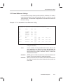
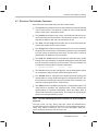
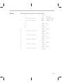
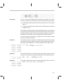
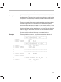
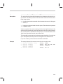
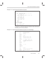
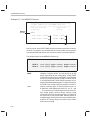
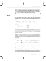
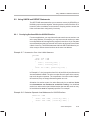
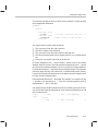
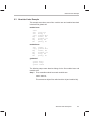
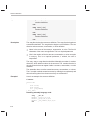
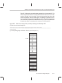
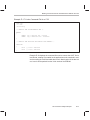
- Program listings, program examples, and interactive displays are shown
in a special typeface similar to a typewriter’s. Examples use a bold
version of the special typeface for emphasis; interactive displays use a
bold version of the special typeface to distinguish commands that you
enter from items that the system displays (such as prompts, command
output, error messages, etc.).
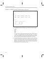
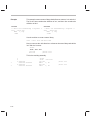
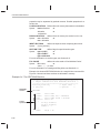
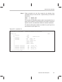
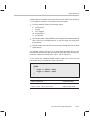
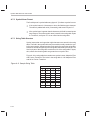
Here is a sample program listing:
0011
0012
0013
0014
0005
0005
0005
0006
0001
0003
0006
.field
.field
.field
.even
1, 2
3, 4
6, 3
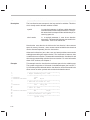
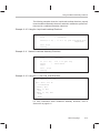
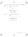
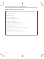
- In syntax descriptions, the instruction, command, or directive is in a bold
typeface font and parameters are in an italic typeface. Portions of a syntax
that are in bold should be entered as shown; portions of a syntax that are
in italics describe the type of information that should be entered. Here is
an example of command line syntax:
asm30 filename
Here asm30 is a command. The command invokes the assembler and
has one parameter, indicated by filename. When you invoke the
assembler, you supply the name of the file that the assembler uses as
input.
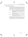
- Square brackets ( [ and ] ) identify an optional parameter. If you use an
optional parameter, you specify the information within the brackets; you
don’t enter the brackets themselves. Here’s an example of an instruction
that has an optional parameter:
hex30 [–options] filename
The hex30 command has two parameters. The first parameter, –options,
is optional. Since options is plural, you may select several options. The
second parameter, filename, is required.
iv
Notational Conventions
Square brackets are also used as part of the pathname specification for
VMS pathnames; in this case, the brackets are actually part of the
pathname (they are not optional).
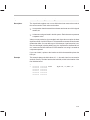
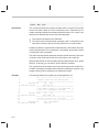
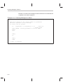
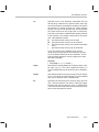
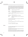
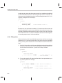
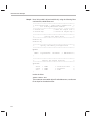
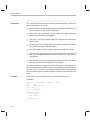
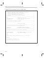
- In assembler syntax statements, column one is reserved for the first
character of a label or symbol. If the label or symbol is optional, it is usually
not shown. If it is a required parameter, then it will be shown starting
against the left margin of the shaded box, as in the example below. No
instruction, command, directive, or parameter, other than a symbol or
label, should begin in column one.
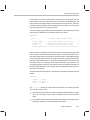
symbol .usect ”section name”, size in bytes
The symbol is required for the .usect directive and must begin in column
one. The section name must be enclosed in quotes, and the section size in
bytes must be separated from the section name by a comma.
- Braces ( { and } ) indicate a list. The symbol | (read as or) separates items
within the list. Here’s an example of a list:
{ * | *+ | *– }
This provides three choices: *, *+, or *–.
Unless the list is enclosed in square brackets, you must choose one item
from the list.
- Some directives can have a varying number of parameters. For example,
the .byte directive can have up to 100 parameters. The syntax for this
directive is:
.byte value1 [, ... , valuen ]
This syntax shows that .byte must have at least one value parameter, but
you have the option of supplying additional value parameters, separated
by commas.
Read This First
v
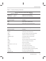
Related Documentation From Texas Instruments
Related Documentation From Texas Instruments
The following books describe the TMS320C3x/C4x and related support tools.
To obtain a copy of any of these TI documents, call the Texas Instruments
Literature Response Center at (800) 477–8924. When ordering, please
identify the book by its title and literature number.
TMS320C3x/C4x Code Generation Tools Getting Started Guide (literature
number SPRU119) describes how to install the TMS320C3x/C4x
assembly language tools and the C compiler. Installation instructions are
included for MS–DOS, Windows 3.x, Windows NT, Windows 95,
SunOS, Solaris, and HP–UX systems.
TMS320C3x/C4x Optimizing C Compiler User’s Guide (literature number
SPRU034) describes the TMS320 floating-point C compiler. This C
compiler accepts ANSI standard C source code and produces TMS320
assembly language source code for the ’C3x and ’C4x generations of
devices.
TMS320C3x C Source Debugger User’s Guide (literature number
SPRU053) tells you how to invoke the ’C3x emulator, evaluation module,
and simulator versions of the C source debugger interface. This book
discusses various aspects of the debugger interface, including window
management, command entry, code execution, data management, and
breakpoints. It also includes a tutorial that introduces basic debugger
functionality.
TMS320C4x C Source Debugger User’s Guide (literature number
SPRU054) tells you how to invoke the ’C4x emulator and simulator
versions of the C source debugger interface. This book discusses
various aspects of the debugger interface, including window
management, command entry, code execution, data management, and
breakpoints. It also includes a tutorial that introduces basic debugger
functionality.
TMS320C3x User’s Guide (literature number SPRU031) describes the ’C3x
32-bit floating-point microprocessor (developed for digital signal
processing as well as general applications), its architecture, internal
register structure, instruction set, pipeline, specifications, and DMA and
serial port operation. Software and hardware applications are included.
TMS320C32 Addendum to the TMS320C3x User’s Guide (literature
number SPRU132) describes the TMS320C32 floating-point
microprocessor (developed for digital signal processing as well as
general applications). Discusses its architecture, internal register
structure, specifications, and DMA and serial port operation. Hardware
applications are also included.
vi
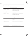
Related Documentation From Texas Instruments
TMS320C4x User’s Guide (literature number SPRU063) describes the ’C4x
32-bit floating-point processor, developed for digital signal processing as
well as parallel processing applications. Covered are its architecture,
internal register structure, instruction set, pipeline, specifications, and
operation of its six DMA channels and six communication ports.
Parallel Processing with the TMS320C4x (literature number SPRA031)
describes parallel processing and how the ’C4x can be used in parallel
processing. Also provides sample parallel processing applications.
TMS320C4x General-Purpose Applications User’s Guide (literature
number SPRU159) describes software and hardware applications for
the ’C4x processor. Also includes development support information,
parts lists, and XDS510 emulator design considerations.
TMS320C30 Evaluation Module Technical Reference (literature number
SPRU069) describes board-level operation of the TMS320C30 EVM.
Digital Signal Processing Applications With the TMS320C30 Evaluation
Module Selected Application Notes (literature number SPRA021)
contains useful information for people who are preparing and debugging
code. The book gives additional information about the TMS320C30
EVM, as well as C coding tips.
TMS320 DSP Development Support Reference Guide (literature number
SPRU011) describes the TMS320 family of digital signal processors and
the tools that support these devices. Included are code-generation tools
(compilers, assemblers, linkers, etc.) and system integration and debug
tools (simulators, emulators, evaluation modules, etc.). Also covered are
available documentation, seminars, the university program, and factory
repair and exchange.
Digital Signal Processing Applications with the TMS320 Family, Volumes
1, 2, and 3 (literature numbers SPRA012, SPRA016, SPRA017)
Volumes 1 and 2 cover applications using the ’C10 and ’C20 families of
fixed-point processors. Volume 3 documents applications using both
fixed-point processors, as well as the ’C30 floating-point processor.
TMS320 DSP Designer’s Notebook: Volume 1 (literature number
SPRT125) presents solutions to common design problems using ’C2x,
’C3x, ’C4x, ’C5x, and other TI DSPs.
TMS320 Third-Party Support Reference Guide (literature number
SPRU052) alphabetically lists over 100 third parties that provide various
products that serve the family of ’320 digital signal processors. A myriad
of products and applications are offered—software and hardware
development tools, speech recognition, image processing, noise
cancellation, modems, etc.
Read This First
vii
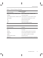
Trademarks
Trademarks
HP-UX is a trademark of Hewlett-Packard Company.
MS-DOS is a registered trademark of Microsoft Corporation.
PC-DOS is a trademark of International Business Machines Corporation.
Solaris is a trademark of Sun Microsystems, Inc.
SunOS is a trademark of Sun Microsystems, Inc.
UNIX is a registered trademark in the United States and other countries,
licensed exclusively through X/Open Company Limited.
XDS is a trademark of Texas Instruments Incorporated.
viii
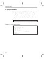
If You Need Assistance
If You Need Assistance . . .
-
World-Wide Web Sites
TI Online
Semiconductor Product Information Center (PIC)
DSP Solutions
320 Hotline On-linet
-
http://www.ti.com
http://www.ti.com/sc/docs/pic/home.htm
http://www.ti.com/dsps
http://www.ti.com/sc/docs/dsps/support.htm
North America, South America, Central America
Product Information Center (PIC)
(972) 644-5580
TI Literature Response Center U.S.A.
(800) 477-8924
Software Registration/Upgrades
(214) 638-0333
Fax: (214) 638-7742
U.S.A. Factory Repair/Hardware Upgrades
(281) 274-2285
U.S. Technical Training Organization
(972) 644-5580
DSP Hotline
(281) 274-2320
Fax: (281) 274-2324
DSP Modem BBS
(281) 274-2323
DSP Internet BBS via anonymous ftp to ftp://ftp.ti.com/pub/tms320bbs
-
Europe, Middle East, Africa
European Product Information Center (EPIC) Hotlines:
Multi-Language Support
+33 1 30 70 11 69
Deutsch
+49 8161 80 33 11 or +33 1 30 70 11 68
English
+33 1 30 70 11 65
Francais
+33 1 30 70 11 64
Italiano
+33 1 30 70 11 67
EPIC Modem BBS
+33 1 30 70 11 99
European Factory Repair
+33 4 93 22 25 40
Europe Customer Training Helpline
-
Email: [email protected]
Fax: +33 1 30 70 10 32 Email: [email protected]
Fax: +49 81 61 80 40 10
Asia-Pacific
Literature Response Center
+852 2 956 7288
Fax: +852 2 956 2200
Hong Kong DSP Hotline
+852 2 956 7268
Fax: +852 2 956 1002
Korea DSP Hotline
+82 2 551 2804
Fax: +82 2 551 2828
Korea DSP Modem BBS
+82 2 551 2914
Singapore DSP Hotline
Fax: +65 390 7179
Taiwan DSP Hotline
+886 2 377 1450
Fax: +886 2 377 2718
Taiwan DSP Modem BBS
+886 2 376 2592
Taiwan DSP Internet BBS via anonymous ftp to ftp://dsp.ee.tit.edu.tw/pub/TI/
-
Japan
Product Information Center
+0120-81-0026 (in Japan)
+03-3457-0972 or (INTL) 813-3457-0972
DSP Hotline
+03-3769-8735 or (INTL) 813-3769-8735
DSP BBS via Nifty-Serve
Type “Go TIASP”
-
Fax: +0120-81-0036 (in Japan)
Fax: +03-3457-1259 or (INTL) 813-3457-1259
Fax: +03-3457-7071 or (INTL) 813-3457-7071
Documentation
When making suggestions or reporting errors in documentation, please include the following information that is on the title
page: the full title of the book, the publication date, and the literature number.
Mail: Texas Instruments Incorporated
Email: [email protected]
Technical Documentation Services, MS 702
P.O. Box 1443
Houston, Texas 77251-1443
Note:
When calling a Literature Response Center to order documentation, please specify the literature number of the
book.
Read This First
ix
Contents
Contents
1
Introduction . . . . . . . . . . . . . . . . . . . . . . . . . . . . . . . . . . . . . . . . . . . . . . . . . . . . . . . . . . . . . . . . . . . . . 1-1
Provides an overview of the assembly language development tools, installation information,
and a walkthrough.
1.1
1.2
2
Software Development Tools Overview . . . . . . . . . . . . . . . . . . . . . . . . . . . . . . . . . . . . . . . . 1-2
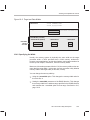
Tools Descriptions . . . . . . . . . . . . . . . . . . . . . . . . . . . . . . . . . . . . . . . . . . . . . . . . . . . . . . . . . . 1-3
Introduction to Common Object File Format . . . . . . . . . . . . . . . . . . . . . . . . . . . . . . . . . . . . . . . 2-1
Discusses the basic COFF concept of sections and how they can help you use the assembler
and linker more efficiently. Common Object File Format, or COFF, is the object file format used
by the TMS320 family floating-point tools. Read Chapter 2 before using the assembler and
linker.
2.1
2.2
2.3
2.4
2.5
2.6
2.7
2.8
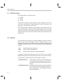
COFF File Types . . . . . . . . . . . . . . . . . . . . . . . . . . . . . . . . . . . . . . . . . . . . . . . . . . . . . . . . . . . 2-2
Sections . . . . . . . . . . . . . . . . . . . . . . . . . . . . . . . . . . . . . . . . . . . . . . . . . . . . . . . . . . . . . . . . . . . 2-2
How the Assembler Handles Sections . . . . . . . . . . . . . . . . . . . . . . . . . . . . . . . . . . . . . . . . . 2-4
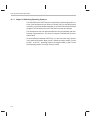
2.3.1 Uninitialized Sections . . . . . . . . . . . . . . . . . . . . . . . . . . . . . . . . . . . . . . . . . . . . . . . . 2-4
2.3.2 Initialized Sections . . . . . . . . . . . . . . . . . . . . . . . . . . . . . . . . . . . . . . . . . . . . . . . . . . . 2-5
2.3.3 Named Sections . . . . . . . . . . . . . . . . . . . . . . . . . . . . . . . . . . . . . . . . . . . . . . . . . . . . . 2-6
2.3.4 Subsections . . . . . . . . . . . . . . . . . . . . . . . . . . . . . . . . . . . . . . . . . . . . . . . . . . . . . . . . 2-8
2.3.5 Section Program Counters . . . . . . . . . . . . . . . . . . . . . . . . . . . . . . . . . . . . . . . . . . . . 2-8
2.3.6 An Example That Uses Sections Directives . . . . . . . . . . . . . . . . . . . . . . . . . . . . . 2-9
How the Linker Handles Sections . . . . . . . . . . . . . . . . . . . . . . . . . . . . . . . . . . . . . . . . . . . . 2-12
2.4.1 Default Allocation . . . . . . . . . . . . . . . . . . . . . . . . . . . . . . . . . . . . . . . . . . . . . . . . . . . 2-12
2.4.2 Placing Sections in the Memory Map . . . . . . . . . . . . . . . . . . . . . . . . . . . . . . . . . . 2-15
Relocation . . . . . . . . . . . . . . . . . . . . . . . . . . . . . . . . . . . . . . . . . . . . . . . . . . . . . . . . . . . . . . . . 2-18
Runtime Relocation . . . . . . . . . . . . . . . . . . . . . . . . . . . . . . . . . . . . . . . . . . . . . . . . . . . . . . . . 2-20
Loading a Program . . . . . . . . . . . . . . . . . . . . . . . . . . . . . . . . . . . . . . . . . . . . . . . . . . . . . . . . 2-21
Symbols in a COFF File . . . . . . . . . . . . . . . . . . . . . . . . . . . . . . . . . . . . . . . . . . . . . . . . . . . . 2-22
2.8.1 External Symbols . . . . . . . . . . . . . . . . . . . . . . . . . . . . . . . . . . . . . . . . . . . . . . . . . . . 2-22
2.8.2 The Symbol Table . . . . . . . . . . . . . . . . . . . . . . . . . . . . . . . . . . . . . . . . . . . . . . . . . . 2-22
xi
Contents
3
Assembler Description . . . . . . . . . . . . . . . . . . . . . . . . . . . . . . . . . . . . . . . . . . . . . . . . . . . . . . . . . . . 3-1
Tells you how to invoke the assembler and discusses source statement format, valid constants
and expressions, and assembler output.
3.1
3.2
3.3
3.4
3.5
3.6
3.7
3.8
3.9
3.10
3.11
3.12
xii
Assembler Overview . . . . . . . . . . . . . . . . . . . . . . . . . . . . . . . . . . . . . . . . . . . . . . . . . . . . . . . . 3-2
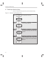
Assembler Development Flow . . . . . . . . . . . . . . . . . . . . . . . . . . . . . . . . . . . . . . . . . . . . . . . . 3-3
Invoking the Assembler . . . . . . . . . . . . . . . . . . . . . . . . . . . . . . . . . . . . . . . . . . . . . . . . . . . . . . 3-4
Porting Upward Compatible Code . . . . . . . . . . . . . . . . . . . . . . . . . . . . . . . . . . . . . . . . . . . . 3-6
Naming Alternate Directories for Assembler Input . . . . . . . . . . . . . . . . . . . . . . . . . . . . . . . 3-7
3.5.1 –i Assembler Option . . . . . . . . . . . . . . . . . . . . . . . . . . . . . . . . . . . . . . . . . . . . . . . . . 3-7
3.5.2 Environment Variable (A_DIR) . . . . . . . . . . . . . . . . . . . . . . . . . . . . . . . . . . . . . . . . 3-8
Source Statement Format . . . . . . . . . . . . . . . . . . . . . . . . . . . . . . . . . . . . . . . . . . . . . . . . . . 3-10
3.6.1 Label Field . . . . . . . . . . . . . . . . . . . . . . . . . . . . . . . . . . . . . . . . . . . . . . . . . . . . . . . . 3-10
3.6.2 Mnemonic Field . . . . . . . . . . . . . . . . . . . . . . . . . . . . . . . . . . . . . . . . . . . . . . . . . . . . 3-11
3.6.3 Operand Field . . . . . . . . . . . . . . . . . . . . . . . . . . . . . . . . . . . . . . . . . . . . . . . . . . . . . . 3-11
3.6.4 Comment Field . . . . . . . . . . . . . . . . . . . . . . . . . . . . . . . . . . . . . . . . . . . . . . . . . . . . . 3-11
Constants . . . . . . . . . . . . . . . . . . . . . . . . . . . . . . . . . . . . . . . . . . . . . . . . . . . . . . . . . . . . . . . . 3-12
3.7.1 Binary Integers . . . . . . . . . . . . . . . . . . . . . . . . . . . . . . . . . . . . . . . . . . . . . . . . . . . . . 3-12
3.7.2 Octal Integers . . . . . . . . . . . . . . . . . . . . . . . . . . . . . . . . . . . . . . . . . . . . . . . . . . . . . . 3-12
3.7.3 Decimal Integers . . . . . . . . . . . . . . . . . . . . . . . . . . . . . . . . . . . . . . . . . . . . . . . . . . . 3-12
3.7.4 Hexadecimal Integers . . . . . . . . . . . . . . . . . . . . . . . . . . . . . . . . . . . . . . . . . . . . . . . 3-13
3.7.5 Character Constants . . . . . . . . . . . . . . . . . . . . . . . . . . . . . . . . . . . . . . . . . . . . . . . . 3-13
3.7.6 Floating-Point Constants . . . . . . . . . . . . . . . . . . . . . . . . . . . . . . . . . . . . . . . . . . . . 3-13
3.7.7 Assembly-Time Constants . . . . . . . . . . . . . . . . . . . . . . . . . . . . . . . . . . . . . . . . . . . 3-14
Character Strings . . . . . . . . . . . . . . . . . . . . . . . . . . . . . . . . . . . . . . . . . . . . . . . . . . . . . . . . . . 3-15
Symbols . . . . . . . . . . . . . . . . . . . . . . . . . . . . . . . . . . . . . . . . . . . . . . . . . . . . . . . . . . . . . . . . . . 3-16
3.9.1 Labels . . . . . . . . . . . . . . . . . . . . . . . . . . . . . . . . . . . . . . . . . . . . . . . . . . . . . . . . . . . . 3-16
3.9.2 Constants . . . . . . . . . . . . . . . . . . . . . . . . . . . . . . . . . . . . . . . . . . . . . . . . . . . . . . . . . 3-16
3.9.3 Symbolic Constants . . . . . . . . . . . . . . . . . . . . . . . . . . . . . . . . . . . . . . . . . . . . . . . . . 3-17
3.9.4 Substitution Symbols . . . . . . . . . . . . . . . . . . . . . . . . . . . . . . . . . . . . . . . . . . . . . . . . 3-18
Expressions . . . . . . . . . . . . . . . . . . . . . . . . . . . . . . . . . . . . . . . . . . . . . . . . . . . . . . . . . . . . . . . 3-20
3.10.1 Floating-Point Expressions . . . . . . . . . . . . . . . . . . . . . . . . . . . . . . . . . . . . . . . . . . 3-20
3.10.2 Floating-Point to Integer Conversions . . . . . . . . . . . . . . . . . . . . . . . . . . . . . . . . . 3-21
3.10.3 Operators . . . . . . . . . . . . . . . . . . . . . . . . . . . . . . . . . . . . . . . . . . . . . . . . . . . . . . . . . 3-22
3.10.4 Expression Overflow or Underflow . . . . . . . . . . . . . . . . . . . . . . . . . . . . . . . . . . . . 3-22
3.10.5 Well-Defined Expressions . . . . . . . . . . . . . . . . . . . . . . . . . . . . . . . . . . . . . . . . . . . 3-22
3.10.6 Conditional Expressions . . . . . . . . . . . . . . . . . . . . . . . . . . . . . . . . . . . . . . . . . . . . . 3-23
3.10.7 Relocatable Symbols and Legal Expressions . . . . . . . . . . . . . . . . . . . . . . . . . . . 3-23
Source Listings . . . . . . . . . . . . . . . . . . . . . . . . . . . . . . . . . . . . . . . . . . . . . . . . . . . . . . . . . . . . 3-25
Cross-Reference Listings . . . . . . . . . . . . . . . . . . . . . . . . . . . . . . . . . . . . . . . . . . . . . . . . . . . 3-27
Contents
4
Assembler Directives . . . . . . . . . . . . . . . . . . . . . . . . . . . . . . . . . . . . . . . . . . . . . . . . . . . . . . . . . . . . 4-1
Describes the directives according to function, and lists the directives in alphabetical order.
4.1
4.2
4.3
4.4
4.5
4.6
4.7
4.8
4.9
4.10
5
Instruction Set . . . . . . . . . . . . . . . . . . . . . . . . . . . . . . . . . . . . . . . . . . . . . . . . . . . . . . . . . . . . . . . . . . 5-1
Summarizes the TMS320C3x and TMS320C4x instruction sets alphabetically and according
to function, with information on addressing modes, optional syntaxes, condition codes and
flags, abbreviations and symbols.
5.1
5.2
5.3
6
Directives Summary . . . . . . . . . . . . . . . . . . . . . . . . . . . . . . . . . . . . . . . . . . . . . . . . . . . . . . . . 4-2
Directives That Define Sections . . . . . . . . . . . . . . . . . . . . . . . . . . . . . . . . . . . . . . . . . . . . . . 4-6
Directives That Initialize Constants . . . . . . . . . . . . . . . . . . . . . . . . . . . . . . . . . . . . . . . . . . . . 4-7
Directives That Align the Section Program Counter . . . . . . . . . . . . . . . . . . . . . . . . . . . . . 4-10
Directives That Format the Output Listing . . . . . . . . . . . . . . . . . . . . . . . . . . . . . . . . . . . . . 4-11
Directives That Reference Other Files . . . . . . . . . . . . . . . . . . . . . . . . . . . . . . . . . . . . . . . . 4-13
Conditional Assembly Directives . . . . . . . . . . . . . . . . . . . . . . . . . . . . . . . . . . . . . . . . . . . . . 4-14
Assembly-Time Symbol Directives . . . . . . . . . . . . . . . . . . . . . . . . . . . . . . . . . . . . . . . . . . . 4-15
Miscellaneous Directives . . . . . . . . . . . . . . . . . . . . . . . . . . . . . . . . . . . . . . . . . . . . . . . . . . . 4-16
Directives Reference . . . . . . . . . . . . . . . . . . . . . . . . . . . . . . . . . . . . . . . . . . . . . . . . . . . . . . . 4-17
Using the Instruction Set Summary . . . . . . . . . . . . . . . . . . . . . . . . . . . . . . . . . . . . . . . . . . . 5-2
5.1.1 Addressing Modes . . . . . . . . . . . . . . . . . . . . . . . . . . . . . . . . . . . . . . . . . . . . . . . . . . . 5-2
5.1.2 Optional Syntax . . . . . . . . . . . . . . . . . . . . . . . . . . . . . . . . . . . . . . . . . . . . . . . . . . . . . 5-3
5.1.3 Condition Codes and Flags . . . . . . . . . . . . . . . . . . . . . . . . . . . . . . . . . . . . . . . . . . . 5-4
5.1.4 Symbols and Abbreviations . . . . . . . . . . . . . . . . . . . . . . . . . . . . . . . . . . . . . . . . . . . 5-6
Functional Summary of the Instruction Set . . . . . . . . . . . . . . . . . . . . . . . . . . . . . . . . . . . . . 5-8
5.2.1 Load-and-Store Instructions . . . . . . . . . . . . . . . . . . . . . . . . . . . . . . . . . . . . . . . . . . 5-8
5.2.2 Arithmetic Instructions . . . . . . . . . . . . . . . . . . . . . . . . . . . . . . . . . . . . . . . . . . . . . . . 5-10
5.2.3 Logic Instructions . . . . . . . . . . . . . . . . . . . . . . . . . . . . . . . . . . . . . . . . . . . . . . . . . . . 5-11
5.2.4 Program-Control Instructions . . . . . . . . . . . . . . . . . . . . . . . . . . . . . . . . . . . . . . . . . 5-11
5.2.5 Interlocked-Operation Instructions . . . . . . . . . . . . . . . . . . . . . . . . . . . . . . . . . . . . 5-12
5.2.6 Conversion Instructions . . . . . . . . . . . . . . . . . . . . . . . . . . . . . . . . . . . . . . . . . . . . . 5-13
5.2.7 Three-Operand Instructions . . . . . . . . . . . . . . . . . . . . . . . . . . . . . . . . . . . . . . . . . . 5-13
5.2.8 Parallel Instructions . . . . . . . . . . . . . . . . . . . . . . . . . . . . . . . . . . . . . . . . . . . . . . . . . 5-14
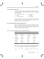
5.2.9 TMS320C4x-Only Instructions . . . . . . . . . . . . . . . . . . . . . . . . . . . . . . . . . . . . . . . . 5-18
5.2.10 LDP and LDPK Instructions . . . . . . . . . . . . . . . . . . . . . . . . . . . . . . . . . . . . . . . . . . 5-19
Instruction Set Summary Table . . . . . . . . . . . . . . . . . . . . . . . . . . . . . . . . . . . . . . . . . . . . . . 5-20
Macro Language . . . . . . . . . . . . . . . . . . . . . . . . . . . . . . . . . . . . . . . . . . . . . . . . . . . . . . . . . . . . . . . . 6-1
Describes an easy way to create your own instructions to better automate repetitive machine
tasks. Included is information on macro directives and substitution symbols used as macro
parameters.
6.1
6.2
Using Macros . . . . . . . . . . . . . . . . . . . . . . . . . . . . . . . . . . . . . . . . . . . . . . . . . . . . . . . . . . . . . . 6-2
Defining Macros . . . . . . . . . . . . . . . . . . . . . . . . . . . . . . . . . . . . . . . . . . . . . . . . . . . . . . . . . . . . 6-3
Contents
xiii
Contents
6.3
6.4
6.5
6.6
6.7
6.8
6.9
6.10
7
Archiver Description . . . . . . . . . . . . . . . . . . . . . . . . . . . . . . . . . . . . . . . . . . . . . . . . . . . . . . . . . . . . . 7-1
Contains instructions for invoking the archiver, creating new archive libraries and modifying
existing libraries.
7.1
7.2
7.3
8
Archiver Development Flow . . . . . . . . . . . . . . . . . . . . . . . . . . . . . . . . . . . . . . . . . . . . . . . . . . 7-2
Invoking the Archiver . . . . . . . . . . . . . . . . . . . . . . . . . . . . . . . . . . . . . . . . . . . . . . . . . . . . . . . . 7-3
Archiver Examples . . . . . . . . . . . . . . . . . . . . . . . . . . . . . . . . . . . . . . . . . . . . . . . . . . . . . . . . . . 7-5
Linker Description . . . . . . . . . . . . . . . . . . . . . . . . . . . . . . . . . . . . . . . . . . . . . . . . . . . . . . . . . . . . . . . 8-1
Describes the process of creating executable modules by combining COFF object files;
describes how to invoke and use the linker, and presents a detailed example.
8.1
8.2
8.3
xiv
Macro Parameters/Substitution Symbols . . . . . . . . . . . . . . . . . . . . . . . . . . . . . . . . . . . . . . . 6-5
6.3.1 Substitution Symbols . . . . . . . . . . . . . . . . . . . . . . . . . . . . . . . . . . . . . . . . . . . . . . . . . 6-5
6.3.2 Directives That Define Substitution Symbols . . . . . . . . . . . . . . . . . . . . . . . . . . . . 6-6
6.3.3 Built-In Substitution Functions . . . . . . . . . . . . . . . . . . . . . . . . . . . . . . . . . . . . . . . . . 6-7
6.3.4 Recursive Substitution Symbols . . . . . . . . . . . . . . . . . . . . . . . . . . . . . . . . . . . . . . . 6-9
6.3.5 Forced Substitution . . . . . . . . . . . . . . . . . . . . . . . . . . . . . . . . . . . . . . . . . . . . . . . . . . 6-9
6.3.6 Accessing Individual Characters of Subscripted Substitution Symbols . . . . . 6-10
6.3.7 Substitution Symbols as Local Variables in Macros . . . . . . . . . . . . . . . . . . . . . . 6-12
Macro Libraries . . . . . . . . . . . . . . . . . . . . . . . . . . . . . . . . . . . . . . . . . . . . . . . . . . . . . . . . . . . . 6-13
Using Conditional Assembly in Macros . . . . . . . . . . . . . . . . . . . . . . . . . . . . . . . . . . . . . . . 6-14
Using Labels in Macros . . . . . . . . . . . . . . . . . . . . . . . . . . . . . . . . . . . . . . . . . . . . . . . . . . . . . 6-16
Producing Messages in Macros . . . . . . . . . . . . . . . . . . . . . . . . . . . . . . . . . . . . . . . . . . . . . 6-17
Formatting the Output Listing . . . . . . . . . . . . . . . . . . . . . . . . . . . . . . . . . . . . . . . . . . . . . . . . 6-19
Using Recursive and Nested Macros . . . . . . . . . . . . . . . . . . . . . . . . . . . . . . . . . . . . . . . . . 6-20
Macro Directives Summary . . . . . . . . . . . . . . . . . . . . . . . . . . . . . . . . . . . . . . . . . . . . . . . . . 6-22
Linker Development Flow . . . . . . . . . . . . . . . . . . . . . . . . . . . . . . . . . . . . . . . . . . . . . . . . . . . . 8-2
Invoking the Linker . . . . . . . . . . . . . . . . . . . . . . . . . . . . . . . . . . . . . . . . . . . . . . . . . . . . . . . . . . 8-4
Linker Options . . . . . . . . . . . . . . . . . . . . . . . . . . . . . . . . . . . . . . . . . . . . . . . . . . . . . . . . . . . . . 8-6
8.3.1 Relocation Capability (–a and –r Options) . . . . . . . . . . . . . . . . . . . . . . . . . . . . . . . 8-7
8.3.2 Disable Merge of Symbolic Debugging Information (–b Option) . . . . . . . . . . . . 8-9
8.3.3 C Language Options (–c and –cr Options) . . . . . . . . . . . . . . . . . . . . . . . . . . . . . . 8-9
8.3.4 Define an Entry Point (–e global symbol Option) . . . . . . . . . . . . . . . . . . . . . . . . . 8-9
8.3.5 Set Default Fill Value (–f cc Option) . . . . . . . . . . . . . . . . . . . . . . . . . . . . . . . . . . . 8-10
8.3.6 Make All Global Symbols Static (–h Option) . . . . . . . . . . . . . . . . . . . . . . . . . . . . 8-10
8.3.7 Keep a Global Symbol (–g symbol Option) . . . . . . . . . . . . . . . . . . . . . . . . . . . . . 8-11
8.3.8 Define Heap Size
(–heap size, –heap8 size, and –heap16 size Options) . . . . . . . . . . . . . . . . . . . 8-11
8.3.9 Alter the Library Search Algorithm (–i dir & –l filename/C_DIR) . . . . . . . . . . . 8-12
8.3.10 –i Linker Option . . . . . . . . . . . . . . . . . . . . . . . . . . . . . . . . . . . . . . . . . . . . . . . . . . . . 8-13
8.3.11 Environment Variable (C_DIR or A_DIR) . . . . . . . . . . . . . . . . . . . . . . . . . . . . . . . 8-13
8.3.12 Create a Map File (–m filename Option) . . . . . . . . . . . . . . . . . . . . . . . . . . . . . . . 8-14
8.3.13 Name an Output Module (–o filename Option) . . . . . . . . . . . . . . . . . . . . . . . . . . 8-14
8.3.14 Specify a Quiet Run (–q Option) . . . . . . . . . . . . . . . . . . . . . . . . . . . . . . . . . . . . . . 8-14
Contents
8.4
8.5
8.6
8.7
8.8
8.9
8.10
8.11
8.12
8.13
8.14
8.15
8.3.15 Strip Symbolic Information (–s Option) . . . . . . . . . . . . . . . . . . . . . . . . . . . . . . . .
8.3.16 Define Stack Size (–stack size Option) . . . . . . . . . . . . . . . . . . . . . . . . . . . . . . . .
8.3.17 Introduce an Unresolved Symbol (–u symbol Option) . . . . . . . . . . . . . . . . . . . .
8.3.18 COFF Format Version (–vn Option) . . . . . . . . . . . . . . . . . . . . . . . . . . . . . . . . . . .
8.3.19 Warning Switch (–w Option) . . . . . . . . . . . . . . . . . . . . . . . . . . . . . . . . . . . . . . . . .
8.3.20 Exhaustively Read Libraries (–x option) . . . . . . . . . . . . . . . . . . . . . . . . . . . . . . .
Linker Command Files . . . . . . . . . . . . . . . . . . . . . . . . . . . . . . . . . . . . . . . . . . . . . . . . . . . . .
Object Libraries . . . . . . . . . . . . . . . . . . . . . . . . . . . . . . . . . . . . . . . . . . . . . . . . . . . . . . . . . . .
The MEMORY Directive . . . . . . . . . . . . . . . . . . . . . . . . . . . . . . . . . . . . . . . . . . . . . . . . . . . .
8.6.1 Default Memory Model . . . . . . . . . . . . . . . . . . . . . . . . . . . . . . . . . . . . . . . . . . . . . .
8.6.2 MEMORY Directive Syntax . . . . . . . . . . . . . . . . . . . . . . . . . . . . . . . . . . . . . . . . . .
The SECTIONS Directive . . . . . . . . . . . . . . . . . . . . . . . . . . . . . . . . . . . . . . . . . . . . . . . . . . .
8.7.1 Default Sections Configuration . . . . . . . . . . . . . . . . . . . . . . . . . . . . . . . . . . . . . . .
8.7.2 SECTIONS Directive Syntax . . . . . . . . . . . . . . . . . . . . . . . . . . . . . . . . . . . . . . . . .
8.7.3 Specifying the Address of Output Sections (Allocation) . . . . . . . . . . . . . . . . . .
8.7.4 Specifying Input Sections . . . . . . . . . . . . . . . . . . . . . . . . . . . . . . . . . . . . . . . . . . . .
Specifying a Section’s Runtime Address . . . . . . . . . . . . . . . . . . . . . . . . . . . . . . . . . . . . . .
8.8.1 Specifying Two Addresses . . . . . . . . . . . . . . . . . . . . . . . . . . . . . . . . . . . . . . . . . . .
8.8.2 Uninitialized Sections . . . . . . . . . . . . . . . . . . . . . . . . . . . . . . . . . . . . . . . . . . . . . . .
8.8.3 Referring to a Load Address by Using the .label Directive . . . . . . . . . . . . . . . .
Using UNION and GROUP Statements . . . . . . . . . . . . . . . . . . . . . . . . . . . . . . . . . . . . . . .
8.9.1 Overlaying Sections With the UNION Directive . . . . . . . . . . . . . . . . . . . . . . . . .
8.9.2 Grouping Output Sections Together . . . . . . . . . . . . . . . . . . . . . . . . . . . . . . . . . . .
Overlay Pages . . . . . . . . . . . . . . . . . . . . . . . . . . . . . . . . . . . . . . . . . . . . . . . . . . . . . . . . . . . .
8.10.1 Using the MEMORY Directive to Define Overlay Pages . . . . . . . . . . . . . . . . . .
8.10.2 Using Overlay Pages With the SECTIONS Directive . . . . . . . . . . . . . . . . . . . .
8.10.3 Page Definition Syntax . . . . . . . . . . . . . . . . . . . . . . . . . . . . . . . . . . . . . . . . . . . . . .
Default Allocation . . . . . . . . . . . . . . . . . . . . . . . . . . . . . . . . . . . . . . . . . . . . . . . . . . . . . . . . . .
8.11.1 Allocation Algorithm . . . . . . . . . . . . . . . . . . . . . . . . . . . . . . . . . . . . . . . . . . . . . . . . .
8.11.2 General Rules for Output Sections . . . . . . . . . . . . . . . . . . . . . . . . . . . . . . . . . . . .
Special Section Types (DSECT, COPY, and NOLOAD) . . . . . . . . . . . . . . . . . . . . . . . . .
Assigning Symbols at Link Time . . . . . . . . . . . . . . . . . . . . . . . . . . . . . . . . . . . . . . . . . . . . .
8.13.1 Syntax of Assignment Statements . . . . . . . . . . . . . . . . . . . . . . . . . . . . . . . . . . . .
8.13.2 Assigning the SPC to a Symbol . . . . . . . . . . . . . . . . . . . . . . . . . . . . . . . . . . . . . .
8.13.3 Assignment Expressions . . . . . . . . . . . . . . . . . . . . . . . . . . . . . . . . . . . . . . . . . . . .
8.13.4 Symbols Defined by the Linker . . . . . . . . . . . . . . . . . . . . . . . . . . . . . . . . . . . . . . .
Creating and Filling Holes . . . . . . . . . . . . . . . . . . . . . . . . . . . . . . . . . . . . . . . . . . . . . . . . . .
8.14.1 Initialized and Uninitialized Sections . . . . . . . . . . . . . . . . . . . . . . . . . . . . . . . . . .
8.14.2 Creating Holes . . . . . . . . . . . . . . . . . . . . . . . . . . . . . . . . . . . . . . . . . . . . . . . . . . . . .
8.14.3 Filling Holes . . . . . . . . . . . . . . . . . . . . . . . . . . . . . . . . . . . . . . . . . . . . . . . . . . . . . . .
8.14.4 Explicit Initialization of Uninitialized Sections . . . . . . . . . . . . . . . . . . . . . . . . . . .
Partial (Incremental) Linking . . . . . . . . . . . . . . . . . . . . . . . . . . . . . . . . . . . . . . . . . . . . . . . .
Contents
8-14
8-15
8-15
8-16
8-16
8-17
8-18
8-21
8-23
8-23
8-23
8-27
8-27
8-27
8-29
8-32
8-35
8-35
8-36
8-36
8-39
8-39
8-41
8-42
8-42
8-44
8-45
8-47
8-47
8-48
8-49
8-50
8-50
8-50
8-51
8-53
8-54
8-54
8-54
8-56
8-57
8-58
xv
Contents
8.16
8.17
9
Linking C Code . . . . . . . . . . . . . . . . . . . . . . . . . . . . . . . . . . . . . . . . . . . . . . . . . . . . . . . . . . . .
8.16.1 Runtime Initialization . . . . . . . . . . . . . . . . . . . . . . . . . . . . . . . . . . . . . . . . . . . . . . . .
8.16.2 Object Libraries and Runtime Support . . . . . . . . . . . . . . . . . . . . . . . . . . . . . . . . .
8.16.3 Setting the Size of the Stack and Heap Sections . . . . . . . . . . . . . . . . . . . . . . . .
8.16.4 Autoinitialization (ROM and RAM Models) . . . . . . . . . . . . . . . . . . . . . . . . . . . . .
8.16.5 The –c and –cr Linker Options . . . . . . . . . . . . . . . . . . . . . . . . . . . . . . . . . . . . . . .
Linker Example . . . . . . . . . . . . . . . . . . . . . . . . . . . . . . . . . . . . . . . . . . . . . . . . . . . . . . . . . . . .
8-60
8-60
8-60
8-61
8-61
8-63
8-64
Absolute Lister Description . . . . . . . . . . . . . . . . . . . . . . . . . . . . . . . . . . . . . . . . . . . . . . . . . . . . . . 9-1
Explains how to invoke the absolute lister to obtain a listing of the absolute addresses of an
object file.
9.1
9.2
9.3
Producing an Absolute Listing . . . . . . . . . . . . . . . . . . . . . . . . . . . . . . . . . . . . . . . . . . . . . . . . 9-2
Invoking the Absolute Lister . . . . . . . . . . . . . . . . . . . . . . . . . . . . . . . . . . . . . . . . . . . . . . . . . . 9-3
Absolute Lister Example . . . . . . . . . . . . . . . . . . . . . . . . . . . . . . . . . . . . . . . . . . . . . . . . . . . . . 9-5
10 Hex Conversion Utility Description . . . . . . . . . . . . . . . . . . . . . . . . . . . . . . . . . . . . . . . . . . . . . . 10-1
Tells you how to use the hex conversion utility to translate a COFF object file into one of several
standard ASCII hexadecimal formats suitable for loading into an EPROM programmer.
10.1
10.2
10.3
10.4
10.5
10.6
10.7
10.8
xvi
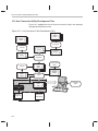
Hex Conversion Utility Development Flow . . . . . . . . . . . . . . . . . . . . . . . . . . . . . . . . . . . . . 10-2
Invoking the Hex Conversion Utility . . . . . . . . . . . . . . . . . . . . . . . . . . . . . . . . . . . . . . . . . . 10-3
Using Command Files . . . . . . . . . . . . . . . . . . . . . . . . . . . . . . . . . . . . . . . . . . . . . . . . . . . . . . 10-6
Creating a Compatible File Format . . . . . . . . . . . . . . . . . . . . . . . . . . . . . . . . . . . . . . . . . . . 10-7
10.4.1 Defining Input Data in the ’C32 . . . . . . . . . . . . . . . . . . . . . . . . . . . . . . . . . . . . . . . 10-8
10.4.2 Specifying the Width . . . . . . . . . . . . . . . . . . . . . . . . . . . . . . . . . . . . . . . . . . . . . . . . 10-9
10.4.3 Partitioning Data Into Output Files . . . . . . . . . . . . . . . . . . . . . . . . . . . . . . . . . . . 10-12
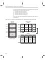
10.4.4 A Memory Configuration Example . . . . . . . . . . . . . . . . . . . . . . . . . . . . . . . . . . . 10-14
10.4.5 Specifying Word Order for Output Files . . . . . . . . . . . . . . . . . . . . . . . . . . . . . . . 10-14
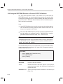
Using the ROMS Directive to Specify Memory Configuration . . . . . . . . . . . . . . . . . . . 10-16
10.5.1 When to Use the ROMS Directive . . . . . . . . . . . . . . . . . . . . . . . . . . . . . . . . . . . 10-18
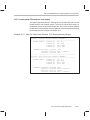
10.5.2 An Example of the ROMS Directive . . . . . . . . . . . . . . . . . . . . . . . . . . . . . . . . . . 10-19
10.5.3 Creating Map Files and the –map option . . . . . . . . . . . . . . . . . . . . . . . . . . . . . . 10-21
Using the SECTIONS Directive to Convert COFF File Sections . . . . . . . . . . . . . . . . . 10-22
Output Filenames . . . . . . . . . . . . . . . . . . . . . . . . . . . . . . . . . . . . . . . . . . . . . . . . . . . . . . . . . 10-24
Image Mode and the –fill Option . . . . . . . . . . . . . . . . . . . . . . . . . . . . . . . . . . . . . . . . . . . . 10-26
10.8.1 The –image Option . . . . . . . . . . . . . . . . . . . . . . . . . . . . . . . . . . . . . . . . . . . . . . . . 10-26
10.8.2 Specifying a Fill Value . . . . . . . . . . . . . . . . . . . . . . . . . . . . . . . . . . . . . . . . . . . . . . 10-27
10.8.3 Steps to Follow in Image Mode . . . . . . . . . . . . . . . . . . . . . . . . . . . . . . . . . . . . . . 10-27
Contents
10.9
Building a Boot-Table From an On-Chip Boot Loader . . . . . . . . . . . . . . . . . . . . . . . . . .
10.9.1 Description of the Boot Table . . . . . . . . . . . . . . . . . . . . . . . . . . . . . . . . . . . . . . . .
10.9.2 The Boot Table Format . . . . . . . . . . . . . . . . . . . . . . . . . . . . . . . . . . . . . . . . . . . . .
10.9.3 How to Build the Boot Table . . . . . . . . . . . . . . . . . . . . . . . . . . . . . . . . . . . . . . . . .
10.9.4 Booting From a Device Peripheral . . . . . . . . . . . . . . . . . . . . . . . . . . . . . . . . . . .
10.9.5 Setting the Entry Point for the Boot Table . . . . . . . . . . . . . . . . . . . . . . . . . . . . .
10.9.6 Setting Control Registers . . . . . . . . . . . . . . . . . . . . . . . . . . . . . . . . . . . . . . . . . . .
10.9.7 Creating a Boot Loader Table for the ’C31 . . . . . . . . . . . . . . . . . . . . . . . . . . . .
10.9.8 TMS320C32 Boot Loader Table Generation . . . . . . . . . . . . . . . . . . . . . . . . . . .
10.9.9 TMS320C4x Boot Loader Table Generation . . . . . . . . . . . . . . . . . . . . . . . . . . .
10.10 Controlling the ROM Device Address . . . . . . . . . . . . . . . . . . . . . . . . . . . . . . . . . . . . . . . .
10.10.1 Controlling the Starting Address . . . . . . . . . . . . . . . . . . . . . . . . . . . . . . . . . . . . .
10.10.2 Controlling the Address Increment Index . . . . . . . . . . . . . . . . . . . . . . . . . . . . .
10.10.3 Dealing With Address Holes . . . . . . . . . . . . . . . . . . . . . . . . . . . . . . . . . . . . . . . .
10.11 Description of the Object Formats . . . . . . . . . . . . . . . . . . . . . . . . . . . . . . . . . . . . . . . . . . .
10.11.1 ASCII-Hex Object Format (–a Option) . . . . . . . . . . . . . . . . . . . . . . . . . . . . . . . .
10.11.2 Intel MCS-86 Object Format (–i Option) . . . . . . . . . . . . . . . . . . . . . . . . . . . . . .
10.11.3 Motorola-S Object Format (–m1, –m2, –m3 Options) . . . . . . . . . . . . . . . . . . .
10.11.4 TI-Tagged Object Format (–t Option) . . . . . . . . . . . . . . . . . . . . . . . . . . . . . . . . .
10.11.5 Extended Tektronix Object Format (–x Option) . . . . . . . . . . . . . . . . . . . . . . . .
10.12 Hex Conversion Utility Error Messages . . . . . . . . . . . . . . . . . . . . . . . . . . . . . . . . . . . . . .
A
10-28
10-28
10-28
10-29
10-31
10-31
10-31
10-32
10-34
10-37
10-39
10-39
10-41
10-42
10-43
10-44
10-45
10-46
10-47
10-48
10-49
Common Object File Format . . . . . . . . . . . . . . . . . . . . . . . . . . . . . . . . . . . . . . . . . . . . . . . . . . . . . . A-1
Contains supplemental technical data about the internal format and structure of COFF object
files.
A.1
A.2
A.3
A.4
A.5
A.6
A.7
How the COFF File Is Structured . . . . . . . . . . . . . . . . . . . . . . . . . . . . . . . . . . . . . . . . . . . . . A-2
A.1.1 Impact of Switching Operating Systems . . . . . . . . . . . . . . . . . . . . . . . . . . . . . . . . A-4
File Header Structure . . . . . . . . . . . . . . . . . . . . . . . . . . . . . . . . . . . . . . . . . . . . . . . . . . . . . . . A-5
Optional File Header Format . . . . . . . . . . . . . . . . . . . . . . . . . . . . . . . . . . . . . . . . . . . . . . . . . A-6
Section Header Structure . . . . . . . . . . . . . . . . . . . . . . . . . . . . . . . . . . . . . . . . . . . . . . . . . . . . A-7
Structuring Relocation Information . . . . . . . . . . . . . . . . . . . . . . . . . . . . . . . . . . . . . . . . . . . A-10
Line-Number Table Structure . . . . . . . . . . . . . . . . . . . . . . . . . . . . . . . . . . . . . . . . . . . . . . . . A-12
Symbol Table Structure and Content . . . . . . . . . . . . . . . . . . . . . . . . . . . . . . . . . . . . . . . . . A-14
A.7.1 Special Symbols . . . . . . . . . . . . . . . . . . . . . . . . . . . . . . . . . . . . . . . . . . . . . . . . . . . A-16
A.7.2 Symbol Name Format . . . . . . . . . . . . . . . . . . . . . . . . . . . . . . . . . . . . . . . . . . . . . . . A-18
A.7.3 String Table Structure . . . . . . . . . . . . . . . . . . . . . . . . . . . . . . . . . . . . . . . . . . . . . . . A-18
A.7.4 Storage Classes . . . . . . . . . . . . . . . . . . . . . . . . . . . . . . . . . . . . . . . . . . . . . . . . . . . . A-19
A.7.5 Symbol Values . . . . . . . . . . . . . . . . . . . . . . . . . . . . . . . . . . . . . . . . . . . . . . . . . . . . . A-20
A.7.6 Section Number . . . . . . . . . . . . . . . . . . . . . . . . . . . . . . . . . . . . . . . . . . . . . . . . . . . . A-21
A.7.7 Type Entry . . . . . . . . . . . . . . . . . . . . . . . . . . . . . . . . . . . . . . . . . . . . . . . . . . . . . . . . . A-21
A.7.8 Auxiliary Entries . . . . . . . . . . . . . . . . . . . . . . . . . . . . . . . . . . . . . . . . . . . . . . . . . . . . A-23
Contents
xvii
Contents
B
Symbolic Debugging Directives . . . . . . . . . . . . . . . . . . . . . . . . . . . . . . . . . . . . . . . . . . . . . . . . . . B-1
Lists several directives that the TMS320 floating-point C compiler uses for symbolic debugging.
C
Assembler Error Messages . . . . . . . . . . . . . . . . . . . . . . . . . . . . . . . . . . . . . . . . . . . . . . . . . . . . . . . C-1
Lists the fatal, nonfatal and macro error messages that the assembler issues.
D
Linker Error Messages . . . . . . . . . . . . . . . . . . . . . . . . . . . . . . . . . . . . . . . . . . . . . . . . . . . . . . . . . . . D-1
Lists all the types of error messages issued by the linker, including syntax and command errors,
allocation errors and I/O errors.
E
Hex Conversion Utility Examples . . . . . . . . . . . . . . . . . . . . . . . . . . . . . . . . . . . . . . . . . . . . . . . . . E-1
Illustrates command file development for a variety of memory systems and situations.
E.1
E.2
E.3
E.4
E.5
E.6
E.7
E.8
F
xviii
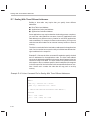
Building a Command File for Two 16-Bit EPROMs . . . . . . . . . . . . . . . . . . . . . . . . . . . . . . E-3
Building a Command File for Booting From the ’C4x Communications Port . . . . . . . . . E-9
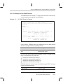
Building a Command File to Convert Code for a ’C32 . . . . . . . . . . . . . . . . . . . . . . . . . . . E-15
Building a Command File for a Four 8-Bit EPROM System . . . . . . . . . . . . . . . . . . . . . . E-20
Avoiding Holes Between Multiple Sections . . . . . . . . . . . . . . . . . . . . . . . . . . . . . . . . . . . . E-21
Building a Command File for a ’C31 Serial Port Boot Load . . . . . . . . . . . . . . . . . . . . . . E-23
Dealing With Three Different Addresses . . . . . . . . . . . . . . . . . . . . . . . . . . . . . . . . . . . . . . E-24
Building a Command File to Generate a Boot Table for the ’C32 . . . . . . . . . . . . . . . . . E-26
Glossary . . . . . . . . . . . . . . . . . . . . . . . . . . . . . . . . . . . . . . . . . . . . . . . . . . . . . . . . . . . . . . . . . . . . . . . . F-1
Explains the terms and phrases and acronyms used in this book.
Figures
Figures
1–1
2–1
2–2
2–3
2–4
2–5
3–1
4–1
4–2
4–3
7–1
8–1
8–2
8–3
8–4
8–5
8–6
8–7
8–8
8–9
8–10
8–11
9–1
9–2
9–3
10–1
10–2
10–3
10–4
10–5
10–6
10–7
10–8
10–9
10–10
10–11
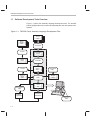
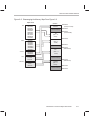
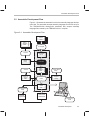
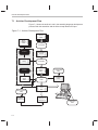
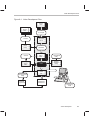
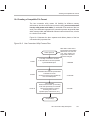
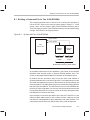
TMS320 Family Assembly Language Development Flow . . . . . . . . . . . . . . . . . . . . . . . . . . . 1-2
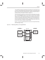
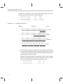
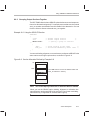
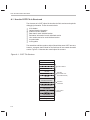
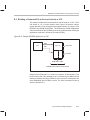
Partitioning Memory Into Logical Blocks . . . . . . . . . . . . . . . . . . . . . . . . . . . . . . . . . . . . . . . . . . 2-3
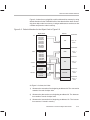
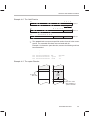
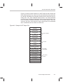
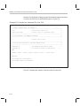
Object Code Generated by Example 2–1 . . . . . . . . . . . . . . . . . . . . . . . . . . . . . . . . . . . . . . . . 2-11
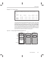
Default Allocation for the Object Code in Figure 2–2 . . . . . . . . . . . . . . . . . . . . . . . . . . . . . . 2-13
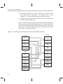
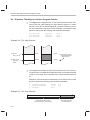
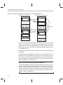
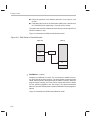
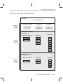
Combining Input Sections From Two Files (Default Allocation) . . . . . . . . . . . . . . . . . . . . . 2-14
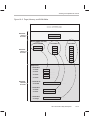
Rearranging the Memory Map From Figure 2–3 . . . . . . . . . . . . . . . . . . . . . . . . . . . . . . . . . . 2-17
Assembler Development Flow . . . . . . . . . . . . . . . . . . . . . . . . . . . . . . . . . . . . . . . . . . . . . . . . . . 3-3
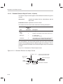
The .align Directive . . . . . . . . . . . . . . . . . . . . . . . . . . . . . . . . . . . . . . . . . . . . . . . . . . . . . . . . . . . 4-18
The .space Directive . . . . . . . . . . . . . . . . . . . . . . . . . . . . . . . . . . . . . . . . . . . . . . . . . . . . . . . . . . 4-62
The .usect Directive . . . . . . . . . . . . . . . . . . . . . . . . . . . . . . . . . . . . . . . . . . . . . . . . . . . . . . . . . . 4-71
Archiver Development Flow . . . . . . . . . . . . . . . . . . . . . . . . . . . . . . . . . . . . . . . . . . . . . . . . . . . . 7-2
Linker Development Flow . . . . . . . . . . . . . . . . . . . . . . . . . . . . . . . . . . . . . . . . . . . . . . . . . . . . . . 8-3
Memory Map Defined in Example 8–3 . . . . . . . . . . . . . . . . . . . . . . . . . . . . . . . . . . . . . . . . . . 8-26
Section Allocation Defined by Example 8–4 . . . . . . . . . . . . . . . . . . . . . . . . . . . . . . . . . . . . . . 8-29
Runtime Execution of Example 8–6 . . . . . . . . . . . . . . . . . . . . . . . . . . . . . . . . . . . . . . . . . . . . . 8-38
Memory Allocation for Example 8–7 and Example 8–8 . . . . . . . . . . . . . . . . . . . . . . . . . . . . 8-40
Section Allocation Defined by Example 8–9 . . . . . . . . . . . . . . . . . . . . . . . . . . . . . . . . . . . . . . 8-41
Overlay Pages Defined by Example 8–10 . . . . . . . . . . . . . . . . . . . . . . . . . . . . . . . . . . . . . . . 8-43
RAM Model of Autoinitialization . . . . . . . . . . . . . . . . . . . . . . . . . . . . . . . . . . . . . . . . . . . . . . . . 8-62
ROM Model of Autoinitialization . . . . . . . . . . . . . . . . . . . . . . . . . . . . . . . . . . . . . . . . . . . . . . . . 8-63
Linker Command File, demo.cmd . . . . . . . . . . . . . . . . . . . . . . . . . . . . . . . . . . . . . . . . . . . . . . 8-65
Output Map File, demo.map . . . . . . . . . . . . . . . . . . . . . . . . . . . . . . . . . . . . . . . . . . . . . . . . . . . 8-66
Absolute Lister Development Flow . . . . . . . . . . . . . . . . . . . . . . . . . . . . . . . . . . . . . . . . . . . . . . 9-2
module1.lst . . . . . . . . . . . . . . . . . . . . . . . . . . . . . . . . . . . . . . . . . . . . . . . . . . . . . . . . . . . . . . . . . . . 9-9
module2.lst . . . . . . . . . . . . . . . . . . . . . . . . . . . . . . . . . . . . . . . . . . . . . . . . . . . . . . . . . . . . . . . . . . 9-10
Hex Conversion Utility Development Flow . . . . . . . . . . . . . . . . . . . . . . . . . . . . . . . . . . . . . . . 10-2
Hex Conversion Utility Process Flow . . . . . . . . . . . . . . . . . . . . . . . . . . . . . . . . . . . . . . . . . . . 10-7
Target and Data Widths . . . . . . . . . . . . . . . . . . . . . . . . . . . . . . . . . . . . . . . . . . . . . . . . . . . . . . . 10-9
Target, Data, and Memory Widths . . . . . . . . . . . . . . . . . . . . . . . . . . . . . . . . . . . . . . . . . . . . . 10-11
Target, Memory, and ROM Widths . . . . . . . . . . . . . . . . . . . . . . . . . . . . . . . . . . . . . . . . . . . . . 10-13
’C3x/’C4x Memory Configuration Example . . . . . . . . . . . . . . . . . . . . . . . . . . . . . . . . . . . . . . 10-14
Varying the Word Order . . . . . . . . . . . . . . . . . . . . . . . . . . . . . . . . . . . . . . . . . . . . . . . . . . . . . . 10-15
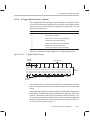
The infile.out File from Example 10–1 Partitioned Into Eight Output Files . . . . . . . . . . . 10-20
ASCII-Hex Object Format . . . . . . . . . . . . . . . . . . . . . . . . . . . . . . . . . . . . . . . . . . . . . . . . . . . . 10-44
Intel Hex Object Format . . . . . . . . . . . . . . . . . . . . . . . . . . . . . . . . . . . . . . . . . . . . . . . . . . . . . . 10-45
Motorola-S Format . . . . . . . . . . . . . . . . . . . . . . . . . . . . . . . . . . . . . . . . . . . . . . . . . . . . . . . . . . 10-46
Contents
xix
Figures
10–12
10–13
A–1
A–2
A–3
A–4
A–5
A–6
A–7
A–8
A–9
E–1
E–2
E–3
E–4
E–5
E–6
E–7
E–8
E–9
xx
TI-Tagged Object Format . . . . . . . . . . . . . . . . . . . . . . . . . . . . . . . . . . . . . . . . . . . . . . . . . . . . . 10-47
Extended Tektronix Hex Object Format . . . . . . . . . . . . . . . . . . . . . . . . . . . . . . . . . . . . . . . . 10-48
COFF File Structure . . . . . . . . . . . . . . . . . . . . . . . . . . . . . . . . . . . . . . . . . . . . . . . . . . . . . . . . . . . A-2
Sample COFF Object File . . . . . . . . . . . . . . . . . . . . . . . . . . . . . . . . . . . . . . . . . . . . . . . . . . . . . . A-3
An Example of Section Header Pointers for the .text Section . . . . . . . . . . . . . . . . . . . . . . . . A-9
Line-Number Blocks . . . . . . . . . . . . . . . . . . . . . . . . . . . . . . . . . . . . . . . . . . . . . . . . . . . . . . . . . . A-12
Line-Number Entries Example . . . . . . . . . . . . . . . . . . . . . . . . . . . . . . . . . . . . . . . . . . . . . . . . . A-13
Symbol Table Contents . . . . . . . . . . . . . . . . . . . . . . . . . . . . . . . . . . . . . . . . . . . . . . . . . . . . . . . A-14
Symbols for Blocks . . . . . . . . . . . . . . . . . . . . . . . . . . . . . . . . . . . . . . . . . . . . . . . . . . . . . . . . . . . A-17
Symbols for Functions . . . . . . . . . . . . . . . . . . . . . . . . . . . . . . . . . . . . . . . . . . . . . . . . . . . . . . . . A-17
Sample String Table . . . . . . . . . . . . . . . . . . . . . . . . . . . . . . . . . . . . . . . . . . . . . . . . . . . . . . . . . . A-18
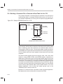
System With Two 16-bit EPROMs . . . . . . . . . . . . . . . . . . . . . . . . . . . . . . . . . . . . . . . . . . . . . . . E-3
Linker Command File for Two 16-bit EPROMs . . . . . . . . . . . . . . . . . . . . . . . . . . . . . . . . . . . . E-4
Data From Output File resulting from Example E–2 . . . . . . . . . . . . . . . . . . . . . . . . . . . . . . . . E-7
A Sample EPROM System for a ’C4x . . . . . . . . . . . . . . . . . . . . . . . . . . . . . . . . . . . . . . . . . . . . E-9
Data From Output File (boot.tbl) resulting from Example E–5 . . . . . . . . . . . . . . . . . . . . . . E-13
Sample EPROM System for a ’C32 . . . . . . . . . . . . . . . . . . . . . . . . . . . . . . . . . . . . . . . . . . . . . E-15
Data from Hex Output File (tutor3.hex) Resulting From Example E–8 . . . . . . . . . . . . . . . E-19
Sample EPROM System for a ’C32 . . . . . . . . . . . . . . . . . . . . . . . . . . . . . . . . . . . . . . . . . . . . . E-26
Output File for Example 8 (example8.hex) Resulting From Example E–18 . . . . . . . . . . . E-30
Tables
Tables
3–1
3–2
3–3
4–1
5–1
5–2
5–3
5–4
5–5
5–6
5–7
5–8
5–9
5–10
5–11
5–12
6–1
6–2
6–3
6–4
6–5
6–6
8–1
8–2
10–1
10–2
10–3
10–4
A–1
A–2
A–3
A–4
A–5
A–6
A–7
A–8
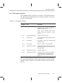
Operators . . . . . . . . . . . . . . . . . . . . . . . . . . . . . . . . . . . . . . . . . . . . . . . . . . . . . . . . . . . . . . . . . . . 3-22
Expressions With Absolute and Relocatable Symbols . . . . . . . . . . . . . . . . . . . . . . . . . . . . . 3-23
Symbol Attributes . . . . . . . . . . . . . . . . . . . . . . . . . . . . . . . . . . . . . . . . . . . . . . . . . . . . . . . . . . . . 3-28
Directives Summary . . . . . . . . . . . . . . . . . . . . . . . . . . . . . . . . . . . . . . . . . . . . . . . . . . . . . . . . . . . 4-2
Indirect Addressing . . . . . . . . . . . . . . . . . . . . . . . . . . . . . . . . . . . . . . . . . . . . . . . . . . . . . . . . . . . . 5-3
Condition Codes and Flags . . . . . . . . . . . . . . . . . . . . . . . . . . . . . . . . . . . . . . . . . . . . . . . . . . . . . 5-5
Instruction Symbols . . . . . . . . . . . . . . . . . . . . . . . . . . . . . . . . . . . . . . . . . . . . . . . . . . . . . . . . . . . 5-6
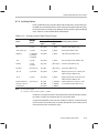
Summary of Load-and-Store Instructions . . . . . . . . . . . . . . . . . . . . . . . . . . . . . . . . . . . . . . . . . 5-9
Summary of Arithmetic Instructions . . . . . . . . . . . . . . . . . . . . . . . . . . . . . . . . . . . . . . . . . . . . . 5-10
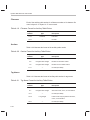
Summary of Logical Instructions . . . . . . . . . . . . . . . . . . . . . . . . . . . . . . . . . . . . . . . . . . . . . . . 5-11
Summary of Program-Control Instructions . . . . . . . . . . . . . . . . . . . . . . . . . . . . . . . . . . . . . . . 5-11
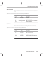
Summary of Interlocked-Operation Instructions . . . . . . . . . . . . . . . . . . . . . . . . . . . . . . . . . . 5-12
Summary of Conversion Instructions . . . . . . . . . . . . . . . . . . . . . . . . . . . . . . . . . . . . . . . . . . . . 5-13
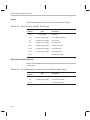
Summary of Three-Operand Instructions . . . . . . . . . . . . . . . . . . . . . . . . . . . . . . . . . . . . . . . . 5-14
Summary of Parallel Instructions . . . . . . . . . . . . . . . . . . . . . . . . . . . . . . . . . . . . . . . . . . . . . . . 5-16
Summary of TMS320C4x-Only Instructions . . . . . . . . . . . . . . . . . . . . . . . . . . . . . . . . . . . . . . 5-18
Function Definitions . . . . . . . . . . . . . . . . . . . . . . . . . . . . . . . . . . . . . . . . . . . . . . . . . . . . . . . . . . . 6-8
Creating Macros . . . . . . . . . . . . . . . . . . . . . . . . . . . . . . . . . . . . . . . . . . . . . . . . . . . . . . . . . . . . . 6-22
Manipulating Substitution Symbols . . . . . . . . . . . . . . . . . . . . . . . . . . . . . . . . . . . . . . . . . . . . . 6-22
Conditional Assembly . . . . . . . . . . . . . . . . . . . . . . . . . . . . . . . . . . . . . . . . . . . . . . . . . . . . . . . . . 6-22
Producing Assembly-Time Messages . . . . . . . . . . . . . . . . . . . . . . . . . . . . . . . . . . . . . . . . . . . 6-23
Formatting the Listing . . . . . . . . . . . . . . . . . . . . . . . . . . . . . . . . . . . . . . . . . . . . . . . . . . . . . . . . . 6-23
Linker Options Summary . . . . . . . . . . . . . . . . . . . . . . . . . . . . . . . . . . . . . . . . . . . . . . . . . . . . . . . 8-6
Operators in Assignment Expressions . . . . . . . . . . . . . . . . . . . . . . . . . . . . . . . . . . . . . . . . . . 8-52
Basic Options . . . . . . . . . . . . . . . . . . . . . . . . . . . . . . . . . . . . . . . . . . . . . . . . . . . . . . . . . . . . . . . 10-4
Boot-Loader Utility Options . . . . . . . . . . . . . . . . . . . . . . . . . . . . . . . . . . . . . . . . . . . . . . . . . . . 10-29
Control Register Options . . . . . . . . . . . . . . . . . . . . . . . . . . . . . . . . . . . . . . . . . . . . . . . . . . . . . 10-32
Options for Specifying Hex Conversion Formats . . . . . . . . . . . . . . . . . . . . . . . . . . . . . . . . . 10-43
File Header Contents . . . . . . . . . . . . . . . . . . . . . . . . . . . . . . . . . . . . . . . . . . . . . . . . . . . . . . . . . . A-5
File Header Flags (Bytes 18 and 19) . . . . . . . . . . . . . . . . . . . . . . . . . . . . . . . . . . . . . . . . . . . . . A-6
Optional File Header Contents . . . . . . . . . . . . . . . . . . . . . . . . . . . . . . . . . . . . . . . . . . . . . . . . . . A-6
Section Header Contents for COFF 0 and COFF1 Files . . . . . . . . . . . . . . . . . . . . . . . . . . . . A-7
Section Header Contents for COFF2 Files . . . . . . . . . . . . . . . . . . . . . . . . . . . . . . . . . . . . . . . . A-7
Section Header Flags . . . . . . . . . . . . . . . . . . . . . . . . . . . . . . . . . . . . . . . . . . . . . . . . . . . . . . . . . . A-8
Relocation Entry Contents . . . . . . . . . . . . . . . . . . . . . . . . . . . . . . . . . . . . . . . . . . . . . . . . . . . . . A-10
Relocation Types (Bytes 8 and 9) . . . . . . . . . . . . . . . . . . . . . . . . . . . . . . . . . . . . . . . . . . . . . . A-11
Contents
xxi
Tables
A–9
A–10
A–11
A–12
A–13
A–14
A–15
A–16
A–17
A–18
A–19
A–20
A–21
A–22
A–23
A–24
A–25
A–26
A–27
xxii
Line-Number Entry Format . . . . . . . . . . . . . . . . . . . . . . . . . . . . . . . . . . . . . . . . . . . . . . . . . . . .
Symbol Table Entry Contents . . . . . . . . . . . . . . . . . . . . . . . . . . . . . . . . . . . . . . . . . . . . . . . . . .
Special Symbols in the Symbol Table . . . . . . . . . . . . . . . . . . . . . . . . . . . . . . . . . . . . . . . . . . .
Symbol Storage Classes . . . . . . . . . . . . . . . . . . . . . . . . . . . . . . . . . . . . . . . . . . . . . . . . . . . . . .
Special Symbols and Their Storage Classes . . . . . . . . . . . . . . . . . . . . . . . . . . . . . . . . . . . . .
Symbol Values and Storage Classes . . . . . . . . . . . . . . . . . . . . . . . . . . . . . . . . . . . . . . . . . . .
Section Numbers . . . . . . . . . . . . . . . . . . . . . . . . . . . . . . . . . . . . . . . . . . . . . . . . . . . . . . . . . . . .
Basic Types . . . . . . . . . . . . . . . . . . . . . . . . . . . . . . . . . . . . . . . . . . . . . . . . . . . . . . . . . . . . . . . . .
Derived Types . . . . . . . . . . . . . . . . . . . . . . . . . . . . . . . . . . . . . . . . . . . . . . . . . . . . . . . . . . . . . . .
Auxiliary Symbol Table Entries Format . . . . . . . . . . . . . . . . . . . . . . . . . . . . . . . . . . . . . . . . . .
Filename Format for Auxiliary Table Entries . . . . . . . . . . . . . . . . . . . . . . . . . . . . . . . . . . . . . .
Section Format for Auxiliary Table Entries . . . . . . . . . . . . . . . . . . . . . . . . . . . . . . . . . . . . . . .
Tag Name Format for Auxiliary Table Entries . . . . . . . . . . . . . . . . . . . . . . . . . . . . . . . . . . . . .
End-of-Structure Format for Auxiliary Table Entries . . . . . . . . . . . . . . . . . . . . . . . . . . . . . . .
Function Format for Auxiliary Table Entries . . . . . . . . . . . . . . . . . . . . . . . . . . . . . . . . . . . . . .
Array Format for Auxiliary Table Entries . . . . . . . . . . . . . . . . . . . . . . . . . . . . . . . . . . . . . . . . .
End-of-Blocks and Functions Format for Auxiliary Table Entries . . . . . . . . . . . . . . . . . . . .
Beginning-of-Blocks and Functions Format for Auxiliary Table Entries . . . . . . . . . . . . . . .
Structure, Union, and Enumeration Names Format for Auxiliary Table Entries . . . . . . . .
A-12
A-15
A-16
A-19
A-20
A-20
A-21
A-22
A-22
A-23
A-24
A-24
A-24
A-25
A-25
A-26
A-26
A-27
A-27
Examples
Examples
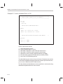
2–1
2–2
2–3
3–1
3–2
4–1
4–2
4–3
4–4
4–5
4–6
4–7
4–8
6–1
6–2
6–3
6–4
6–5
6–6
6–7
6–8
6–9
6–10
6–11
6–12
6–13
6–14
6–15
6–16
8–1
8–2
8–3
8–4
8–5
8–6
8–7
Using Section Directives . . . . . . . . . . . . . . . . . . . . . . . . . . . . . . . . . . . . . . . . . . . . . . . . . . . . . . 2-10
MEMORY and SECTIONS Directives for Figure 2–5 . . . . . . . . . . . . . . . . . . . . . . . . . . . . . . 2-16
Code That Generates Relocation Entries . . . . . . . . . . . . . . . . . . . . . . . . . . . . . . . . . . . . . . . . 2-18
An Assembler Listing . . . . . . . . . . . . . . . . . . . . . . . . . . . . . . . . . . . . . . . . . . . . . . . . . . . . . . . . . 3-26
An Assembler Cross-Reference Listing . . . . . . . . . . . . . . . . . . . . . . . . . . . . . . . . . . . . . . . . . 3-27
Initialization Directives . . . . . . . . . . . . . . . . . . . . . . . . . . . . . . . . . . . . . . . . . . . . . . . . . . . . . . . . . 4-8
The .field Directive . . . . . . . . . . . . . . . . . . . . . . . . . . . . . . . . . . . . . . . . . . . . . . . . . . . . . . . . . . . . 4-9
The .space Directive . . . . . . . . . . . . . . . . . . . . . . . . . . . . . . . . . . . . . . . . . . . . . . . . . . . . . . . . . . . 4-9
The .align Directive . . . . . . . . . . . . . . . . . . . . . . . . . . . . . . . . . . . . . . . . . . . . . . . . . . . . . . . . . . . 4-10
The .even Directive . . . . . . . . . . . . . . . . . . . . . . . . . . . . . . . . . . . . . . . . . . . . . . . . . . . . . . . . . . . 4-10
The .even Directive . . . . . . . . . . . . . . . . . . . . . . . . . . . . . . . . . . . . . . . . . . . . . . . . . . . . . . . . . . . 4-32
The .field Directive . . . . . . . . . . . . . . . . . . . . . . . . . . . . . . . . . . . . . . . . . . . . . . . . . . . . . . . . . . . 4-36
Defining Two Uninitialized, Named Sections . . . . . . . . . . . . . . . . . . . . . . . . . . . . . . . . . . . . . 4-71
Macro Definition, Call, and Expansion . . . . . . . . . . . . . . . . . . . . . . . . . . . . . . . . . . . . . . . . . . . 6-4
Calling a Macro With Varying Numbers of Arguments . . . . . . . . . . . . . . . . . . . . . . . . . . . . . . 6-6
Using the .asg Directive . . . . . . . . . . . . . . . . . . . . . . . . . . . . . . . . . . . . . . . . . . . . . . . . . . . . . . . . 6-7
Using the .eval Directive . . . . . . . . . . . . . . . . . . . . . . . . . . . . . . . . . . . . . . . . . . . . . . . . . . . . . . . 6-7
Using Built-In Substitution Symbol Functions to Redefine an Instruction . . . . . . . . . . . . . . 6-8
Recursive Substitution . . . . . . . . . . . . . . . . . . . . . . . . . . . . . . . . . . . . . . . . . . . . . . . . . . . . . . . . . 6-9
Using the Forced Substitution Operator . . . . . . . . . . . . . . . . . . . . . . . . . . . . . . . . . . . . . . . . . 6-10
Using Subscripted Substitution Symbols . . . . . . . . . . . . . . . . . . . . . . . . . . . . . . . . . . . . . . . . 6-11
Using Subscripted Substitution Symbols to Find Substrings . . . . . . . . . . . . . . . . . . . . . . . . 6-11
Using the .loop/.break/.endloop Directives . . . . . . . . . . . . . . . . . . . . . . . . . . . . . . . . . . . . . . . 6-15
Nested Conditional Assembly Directives . . . . . . . . . . . . . . . . . . . . . . . . . . . . . . . . . . . . . . . . 6-15
Using the .if, .else, and .endif Directives . . . . . . . . . . . . . . . . . . . . . . . . . . . . . . . . . . . . . . . . . 6-15
Unique Labels in a Macro . . . . . . . . . . . . . . . . . . . . . . . . . . . . . . . . . . . . . . . . . . . . . . . . . . . . . 6-16
Producing Messages in a Macro . . . . . . . . . . . . . . . . . . . . . . . . . . . . . . . . . . . . . . . . . . . . . . . 6-18
Using Nested Macros . . . . . . . . . . . . . . . . . . . . . . . . . . . . . . . . . . . . . . . . . . . . . . . . . . . . . . . . . 6-20
Using Recursive Macros . . . . . . . . . . . . . . . . . . . . . . . . . . . . . . . . . . . . . . . . . . . . . . . . . . . . . . 6-21
An Example of a Linker Command File . . . . . . . . . . . . . . . . . . . . . . . . . . . . . . . . . . . . . . . . . . 8-18
A Command File With Linker Directives . . . . . . . . . . . . . . . . . . . . . . . . . . . . . . . . . . . . . . . . . 8-19
The MEMORY Directive . . . . . . . . . . . . . . . . . . . . . . . . . . . . . . . . . . . . . . . . . . . . . . . . . . . . . . 8-24
The SECTIONS Directive . . . . . . . . . . . . . . . . . . . . . . . . . . . . . . . . . . . . . . . . . . . . . . . . . . . . . 8-28
The Most Common Method of Specifying Section Contents . . . . . . . . . . . . . . . . . . . . . . . . 8-32
Copying a Section From ROM to RAM . . . . . . . . . . . . . . . . . . . . . . . . . . . . . . . . . . . . . . . . . . 8-37
Illustrates the Form of the UNION Statement . . . . . . . . . . . . . . . . . . . . . . . . . . . . . . . . . . . . 8-39
Contents
xxiii
Examples
8–8
8–9
8–10
8–11
10–1
10–2
10–3
10–4
10–5
10–6
E–1
E–2
E–3
E–4
E–5
E–6
E–7
E–8
E–9
E–10
E–11
E–12
E–13
E–14
E–15
E–16
E–17
E–18
xxiv
Illustrates Separate Load Addresses for UNION Sections . . . . . . . . . . . . . . . . . . . . . . . . . 8-39
Using the GROUP Directive . . . . . . . . . . . . . . . . . . . . . . . . . . . . . . . . . . . . . . . . . . . . . . . . . . . 8-41
Overlay Pages . . . . . . . . . . . . . . . . . . . . . . . . . . . . . . . . . . . . . . . . . . . . . . . . . . . . . . . . . . . . . . . 8-43
SECTIONS Directive Definition for Figure 8–7 . . . . . . . . . . . . . . . . . . . . . . . . . . . . . . . . . . . 8-44
A ROMS Directive Example . . . . . . . . . . . . . . . . . . . . . . . . . . . . . . . . . . . . . . . . . . . . . . . . . . 10-19
Map File Output from Example 10–1 Showing Memory Ranges . . . . . . . . . . . . . . . . . . . 10-21
Using the TMS320C31 Boot Loader . . . . . . . . . . . . . . . . . . . . . . . . . . . . . . . . . . . . . . . . . . . 10-33
Using the TMS320C32 Boot Loader . . . . . . . . . . . . . . . . . . . . . . . . . . . . . . . . . . . . . . . . . . . 10-36
Using the ’C4x Boot Loader . . . . . . . . . . . . . . . . . . . . . . . . . . . . . . . . . . . . . . . . . . . . . . . . . . 10-38
Hex Command File For Hole Avoidance . . . . . . . . . . . . . . . . . . . . . . . . . . . . . . . . . . . . . . . . 10-42
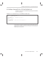
Sample ASM Code . . . . . . . . . . . . . . . . . . . . . . . . . . . . . . . . . . . . . . . . . . . . . . . . . . . . . . . . . . . . E-2
Command File for Two 16-bit EPROMs . . . . . . . . . . . . . . . . . . . . . . . . . . . . . . . . . . . . . . . . . . E-6
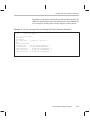
Hex Conversion Map File Resulting From Example E–2 . . . . . . . . . . . . . . . . . . . . . . . . . . . . E-8
Linker Command File for Booting From the ’C4x COMM Port . . . . . . . . . . . . . . . . . . . . . . E-10
Command File for Booting From the ’C4x COMM Port . . . . . . . . . . . . . . . . . . . . . . . . . . . . E-12
Map File Resulting From Example E–5 . . . . . . . . . . . . . . . . . . . . . . . . . . . . . . . . . . . . . . . . . . E-14
Linker Command File for a ’C32 . . . . . . . . . . . . . . . . . . . . . . . . . . . . . . . . . . . . . . . . . . . . . . . . E-16
Sample Hex Command File for a ’C32 . . . . . . . . . . . . . . . . . . . . . . . . . . . . . . . . . . . . . . . . . . E-18
Code for Four 8-Bit EPROM Files . . . . . . . . . . . . . . . . . . . . . . . . . . . . . . . . . . . . . . . . . . . . . . E-20
Linker Command File for Avoiding Holes: Method One . . . . . . . . . . . . . . . . . . . . . . . . . . . . E-21
Hex Conversion Utility Command File for Avoiding Holes: Method One . . . . . . . . . . . . . . E-22
Linker Command File for Avoiding Holes: Method Two . . . . . . . . . . . . . . . . . . . . . . . . . . . . E-22
Hex Conversion Utility Command File for Avoiding Holes: Method Two . . . . . . . . . . . . . . E-22
Command File for a ’C31 SERIAL Port Boot Load . . . . . . . . . . . . . . . . . . . . . . . . . . . . . . . . E-23
Linker Command File for Dealing With Three Different Addresses . . . . . . . . . . . . . . . . . . E-24
Hex Command File for Dealing With Three Different Addresses . . . . . . . . . . . . . . . . . . . . E-25
Linker Command File for a ’C32 . . . . . . . . . . . . . . . . . . . . . . . . . . . . . . . . . . . . . . . . . . . . . . . . E-27
Hex Command File For a ’C32 Boot Table . . . . . . . . . . . . . . . . . . . . . . . . . . . . . . . . . . . . . . . E-28
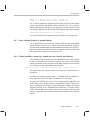
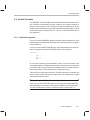
Chapter 1
Introduction
The TMS320C3x/C4x DSPs are supported by the following assembly
language tools:
-
Assembler
Archiver
Linker
Hex conversion utility
This chapter shows how these tools fit into the general software tools development flow and gives a brief description of each tool. For convenience, it also
summarizes the C compiler and debugging tools; however, the compiler and
debugger are not shipped with the assembly language tools. For detailed
information on the compiler and debugger and for complete descriptions of the
TMS320C3x/C4x devices, refer to books listed in Related Documentation
From Texas Instruments, page vi.
The assembly language tools create and use object files in common object file
format (COFF) to facilitate modular programming. Object files contain separate blocks (called sections) of code and data that you can load into TMS320
memory spaces. You can program the TMS320 devices more efficiently if you
have a basic understanding of COFF. Chapter 2, Introduction to Common
Object File Format, discusses this object format in detail.
Topic
Page
1.1
Software Development Tools Overview . . . . . . . . . . . . . . . . . . . . . . . . . 1-2
1.2
Tools Descriptions . . . . . . . . . . . . . . . . . . . . . . . . . . . . . . . . . . . . . . . . . . . . 1-3
Introduction
1-1
Software Development Tools Overview
1.1 Software Development Tools Overview
Figure 1–1 shows the assembly language development flow. The shaded
portion highlights the most common development path; the other portions are
optional.
Figure 1–1. TMS320 Family Assembly Language Development Flow
C
Source
Files
Macro
Source
Files
C Compiler
Archiver
Macro
Library
Archiver
Library of
Object
Files
Hex Conversion
Utility
EPROM
Programmer
Assembler
Source
Assembler
COFF
Object
Files
Linker
Library Build
Utility
Runtime
Support
Library
Executable
COFF
File
TMS320C3x
TMS320C4x
Debugging
Tools
1-2
Tools Descriptions
1.2 Tools Descriptions
- The C compiler translates C source code into TMS320C3x or
TMS320C4x assembly language source code. The C compiler is not included as part of the assembly language tools package.
- The assembler translates assembly language source files into machine
language object files. Source files can contain instructions, assembler
directives, and macro directives. You can use assembler directives to control various aspects of the assembly process, such as the source listing
format, data alignment, and section content.
- The linker combines object files into a single executable object module.
As it creates the executable module, it performs relocation and resolves
external references. The linker accepts relocatable COFF object files (created by the assembler) as input. It also accepts archiver library members
and output modules created by a previous linker run. Linker directives
allow you to combine object file sections, bind sections or symbols to addresses or within memory ranges, and define or redefine global symbols.
- The archiver allows you to collect a group of files into a single archive file.
For example, you can collect several macros together into a macro library.
The assembler will search through the library and use the members that
are called as macros by the source file. You can also use the archiver to
collect a group of object files into an object library. The linker will include
the members in the library that resolve external references during the link.
- The absolute lister accepts linked object files as input and creates .abs
files as output. You assemble .abs files to produce a listing that contains
absolute rather than relative addresses. Without the absolute lister, producing such a listing would be tedious and require many manual operations.
- The main purpose of this development process is to produce a module that
can be executed in a system that contains a TMS320 device. There are
several debugging tools available for the various TMS320 devices:
J
The simulator is a software program that simulates TMS320 instructions. The simulator can execute linked COFF object modules. The
simulator is not included with the assembly language package.
J
The XDS (extended development support) emulator is a real–time,
in-circuit emulator with the same screen–oriented interface as the
software simulator. The emulator is not included with the assembly
language package.
Introduction
1-3
Tools Descriptions
J
The evaluation module (EVM) is a low-cost development board that
provides full-speed in-circuit emulation and hardware debugging. The
EVM is available now for the TMS320C3x devices and will be available soon for the TMS320C4x devices.
J
The C source debugger is a software interface to the simulator, emulator, and EVM.
- The TMS320C3x/4x devices accept COFF files as input, but most
EPROM programmers do not. The hex conversion utility converts a
COFF object file into TI–tagged, Intel, Motorola S1/S2/S3, or Tektronix
object format. The converted file can be downloaded to an EPROM
programmer.
1-4
Chapter 2
Introduction to Common Object File Format
The assembler and linker create object files that can be executed by a
TMS320C3x/C4x device. The format that these object files are in is called
common object file format, or COFF.
COFF makes modular programming easier because it encourages you to
think in terms of blocks of code and data when you write an assembly language
program. These blocks are known as sections. Both the assembler and the
linker provide directives that allow you to create and manipulate sections.
In addition to this chapter, Appendix A details COFF object file structure. For
example, it describes the fields in a file header and the structure of a symbol
table entry. Appendix A is useful mainly for those of you who are interested in
the internal format of object files.
Topic
Page
2.1
COFF File Types . . . . . . . . . . . . . . . . . . . . . . . . . . . . . . . . . . . . . . . . . . . . . . 2-2
2.2
Sections . . . . . . . . . . . . . . . . . . . . . . . . . . . . . . . . . . . . . . . . . . . . . . . . . . . . . 2-2
2.3
How the Assembler Handles Sections . . . . . . . . . . . . . . . . . . . . . . . . . . 2-4
2.4
How the Linker Handles Sections . . . . . . . . . . . . . . . . . . . . . . . . . . . . . 2-12
2.5
Relocation . . . . . . . . . . . . . . . . . . . . . . . . . . . . . . . . . . . . . . . . . . . . . . . . . . . 2-18
2.6
Runtime Relocation . . . . . . . . . . . . . . . . . . . . . . . . . . . . . . . . . . . . . . . . . . 2-20
2.7
Loading a Program . . . . . . . . . . . . . . . . . . . . . . . . . . . . . . . . . . . . . . . . . . . 2-21
2.8
Symbols in a COFF File . . . . . . . . . . . . . . . . . . . . . . . . . . . . . . . . . . . . . . . 2-22
Introduction to Common Object File Format
2-1
COFF File Types
2.1 COFF File Types
The following types of COFF files exist:
- COFF0
- COFF1
- COFF2
Each COFF file type has a different header format. The data portions of the
COFF files are identical. For details about the COFF file structure, see
Appendix A, Common Object File Format.
The TMS320C3x/C4x assembler and C compiler create COFF2 files. The
linker can read and write all types of COFF files. By default, the linker creates
COFF2 files. Use the –v linker option to specify a different format. The linker
supports COFF0 and COFF1 files for older versions of the assembler and C
compiler only.
2.2 Sections
The smallest unit of an object file is called a section. A section is a block of
code or data that will ultimately occupy contiguous space in the
TMS320C3x/C4x memory map. Each section of an object file is separate and
distinct from the other sections. COFF object files always contain three default
sections:
.text
usually contains executable code.
.data
usually contains initialized data.
.bss
usually reserves space for uninitialized variables.
In addition, the assembler and linker allow you to create, name, and link
named sections that are used similarly to the .data, .text, and .bss sections.
It is important to note that there are two basic types of sections:
Initialized sections
contain data or code. The .text and .data sections
are initialized; named sections created with the
.sect and .asect assembler directives are also initialized.
Uninitialized sections reserve space in the memory map for uninitialized
data. The .bss section is uninitialized; named sections created with the .usect assembler directive
are also uninitialized.
2-2
Sections
The assembler provides several directives that allow you to associate various
portions of code and data with the appropriate sections. The assembler builds
these sections during the assembly process, creating an object file that is organized similarly to the object file shown in Figure 2–1.
One of the linker’s functions is to relocate sections into the target memory map;
this is called allocation. Because most systems contain several different
types of memory, using sections can help you to use target memory more efficiently. All sections are independently relocatable; you can place different sections into various blocks of target memory. For example, you can define a section that contains an initialization routine and then allocate the routine into a
portion of the memory map that contains EPROM.
Figure 2–1 shows the relationship between sections in an object file and a hypothetical target memory.
Figure 2–1. Partitioning Memory Into Logical Blocks
Initialized
Program Memory
Object File
Uninitialized
Data Memory
External
EPROM
.data
on-chip
RAM
External
EPROM
.text
.bss
Introduction to Common Object File Format
2-3
How the Assembler Handles Sections
2.3 How the Assembler Handles Sections
The assembler identifies the portions of an assembly language program that
belong in a section. The assembler has six directives that support this function:
-
.bss
.usect
.text
.data
.sect
.asect
The .bss and .usect directives create uninitialized sections; the .text, .data,
.sect, and .asect directives create initialized sections.
Note:
Default Section Directive
If you don’t use any of the sections directives, the assembler assembles
everything into the .text section.
2.3.1
Uninitialized Sections
Uninitialized sections reserve space in TMS320C3x/C4x memory; they are
usually allocated into RAM. These sections have no actual contents in the
object file; they simply reserve memory. A program can use this space at run
time for creating and storing variables.
Uninitialized data areas are built by using the .bss and .usect assembler
directives. The .bss directive reserves space in the .bss section. The .usect
directive reserves space in a specific uninitialized named section. Each time
you invoke the .bss directive, the assembler reserves more space in the .bss
section. Each time you invoke the .usect directive, the assembler reserves
more space in the specified named section.
The syntax for each directive is
.bss symbol, size in words
symbol .usect ”section name ”, size in words [alignment flag]
2-4
How the Assembler Handles Sections
symbol
points to the first byte reserved by this invocation of the .bss
or .usect directive. The symbol corresponds to the name of
the variable for which you’re reserving space. It can be referenced by any other section and can also be declared as
a global symbol (with the .global assembler directive).
size
is an absolute expression. The .bss directive reserves size
words in the .bss section; the .usect directive reserves size
words in section name. There is no default size for the .bss
section.
section name
tells the assembler which named section to reserve space
in. For more information about named sections, refer to
subsection 2.3.3.
blocking flag
is an optional parameter. If present and nonzero, the flag
means that this section will be blocked. Blocking is an address alignment mechanism similar to alignment, but
weaker. It means a section is guaranteed not to cross a
page boundary (128 words) if it is smaller than a page, and
to start on a page boundary if it is larger than a page. This
blocking applies to the section, not to the object declared
with this instance of the .usect directive.
alignment flag
is an optional parameter. If present and nonzero, the section will be aligned to a long word boundary.
The .text, .data, .sect, and .asect directives tell the assembler to stop
assembling into the current section and begin assembling into the indicated
section. The .bss and .usect directives, however, do not end the current
section and begin a new one; they simply escape from the current section
temporarily. The .bss and .usect directives can appear anywhere in an initialized section without affecting the contents of the initialized section.
2.3.2
Initialized Sections
Initialized sections contain executable code or initialized data. The contents
of these sections are stored in the object file and placed in TMS320C3x/C4x
memory when the program is loaded. Each initialized section is separately
relocatable and may reference symbols that are defined in other sections. The
linker automatically resolves these section-relative references.
Introduction to Common Object File Format
2-5
How the Assembler Handles Sections
Three directives tell the assembler to place code or data into a section. The
syntax for each directive is
.text
.data
.sect ”section name” [, value]
When the assembler encounters one of these directives, it stops assembling
into the current section; the directive acts as an implied “end current section”
command. The assembler then assembles subsequent code into the section
designated by the directive until it encounters another .text, .data, or .sect
directive.
Sections are built up through an iterative process. For example, when the assembler first encounters a .data directive, the .data section is empty. The statements following this first .data directive are assembled into the .data section
(until the assembler encounters a .text, .sect, or .asect directive). If the assembler encounters subsequent .data directives, it adds the statements following
these .data directives to the statements that are already in the .data section.
This creates a single .data section that can be allocated contiguously into
memory.
2.3.3
Named Sections
Named sections are sections that you create. You can use them like the default
.text, .data, and .bss sections, but they are assembled separately from the default sections.
For example, repeated use of the .text directive builds up a single .text section
in the object file. When linked, this .text section is allocated into memory as a
single unit. Suppose there is a portion of executable code (perhaps an initialization routine) that you don’t want allocated with .text. If you assemble this
segment of code into a named section, it will be assembled separately from
.text, and you will be able to allocate it into memory separately from .text. Note
that you can also assemble initialized data that is separate from the .data section, and you can reserve space for uninitialized variables that is separate from
the .bss section.
Three directives let you create named sections:
- The .usect directive creates sections that are used like the .bss section.
These sections reserve space in RAM for variables.
- The .sect directive creates sections that can contain code or data, similar
to the default .text and .data sections. The .sect directive creates named
sections with relocatable addresses.
2-6
How the Assembler Handles Sections
The syntax for each directive is:
symbol .usect “section name”, size in words [, alignment flag]
.sect “section name”[, value]
The section name parameter is the name of the section. Section names are
significant to 8 characters. You can create up to 32,767 separate named sections.
Each time you invoke one of these directives with a new name, you create a
new named section. Each time you invoke one of these directives with a name
that was already used, the assembler assembles code or data (or reserves
space) into the section with that name. You cannot use the same names with
different directives. That is, you cannot create a section with the .usect directive and then try to use the same section with .sect.
Introduction to Common Object File Format
2-7
How the Assembler Handles Sections
2.3.4
Subsections
Subsections are smaller sections within larger sections. Like sections, subsections can be manipulated by the linker. Subsections give you tighter control
of the memory map. You can create subsections by using the .sect or .usect
directive. The syntax for a subsection name is:
section name:subsection name
A subsection is identified by the base section name followed by a colon, then
the name of the subsection. A subsection can be allocated separately or
grouped with other sections using the same base name. For example, to
create a subsection called _func within the .text section, enter the following:
.sect ”.text:_func”
You can allocate _func separately or within all the .text sections.
You can create two types of subsections:
- Initialized subsections are created using the .sect directive. See subsec-
tion 2.3.2, Initialized Sections, on page 2-5.
- Uninitialized subsections are created using the .usect directive. See
subsection 2.3.1, Uninitialized Sections, on page 2-4.
Subsections are allocated in the same manner as sections. See Section 8.7,
The SECTIONS Directive, on page 8-27 for more information.
2.3.5
Section Program Counters
The assembler maintains a separate program counter for each section. These
program counters are known as section program counters, or SPCs.
An SPC represents the current address within a section of code or data.
Initially, the assembler sets each SPC to 0. As the assembler fills a section with
code or data, it increments the appropriate SPC. If you resume assembling into
a section, the assembler remembers the appropriate SPC’s previous value
and continues incrementing the SPC at that point.
The assembler treats each section as if it begins at address 0; the linker relocates each section according to its final location in the memory map.
2-8
How the Assembler Handles Sections
2.3.6
An Example That Uses Sections Directives
Figure 2–1 shows how you can build COFF sections incrementally, using the
sections directives to swap back and forth between the different sections. You
can use sections directives to
- Begin assembling into a section for the first time, or
- Continue assembling into a section that already contains code. In this
case, the assembler simply appends the new code to the code that is already in the section.
The format in this example is a listing file. Example 2–1 shows how the SPCs
are modified during assembly. A line in a listing file has four fields:
Field 1
contains the source code line counter.
Field 2
contains the section program counter.
Field 3
contains the object code.
Field 4
contains the original source statement.
Introduction to Common Object File Format
2-9
How the Assembler Handles Sections
Example 2–1. Using Section Directives
1
2
3
4
5
6
7
8
9
10
11
12
13
14
15
16
17
18
19
20
21
22
23
24
25
26
27
28
29
30
31
32
33
34
35
36
37
38
39
40
41
42
43
44
45
46
47
48
49
50
51
52
53
54
55
00000000
00000000
00000001
00000002
00000000
00000001
**********************************************
** Reserve space in .bss for two variables **
***********************************************
.bss
var1,1
.bss
buffer, 10
00000003
***********************************************
**
Still in data
**
***********************************************
ptr
.word
0123h
00000000
00000000
00000001
00000002
00000002
00000003
00000004
00000004
00000004
00000005
00000006
00000123
0869000a
08610000
02412001
6e46fffe
15210000–
000000aa
000000bb
000000cc
**********************************************
**
Assemble code into .text section
**
**********************************************
.text
add:
LDI
10,AR1
LDI
0,R1
aloop:
ADDI
*AR0++,R1
DBNZ
AR1,aloop
STI
R1,@var1
**********************************************
**
Assemble another initialized table **
**
into the data section
**
**********************************************
.data
ivals .word
0AAh, 0BBh, 0CCh
00000000
00000001
**********************************************
** Define another section for more variables**
***********************************************
var2
.usect
”newvars”,1
inbuf .usect
”newvars”,7
00000005
00000005
00000006
00000007
00000007
00000008
00000009
*********************************************
** Assemble more code into .text section
**
**********************************************
.text
mpy:
LDI
10,AR1
LDI
0,R1
mloop:
MPYI
*AR0++,R1
DBNZ
AR1,mloop
STI
R1,@var2
00000000
00000000
00000001
Field 1 Field 2
2-10
00000011
00000022
00000033
**********************************************
** Assemble an initialized table into data **
**********************************************
.data
coeff .word
011h, 022h, 033h
0869000a
08610000
0ac12001
6e46fffe
15210000–
00000000’
00000005’
Field 3
**********************************************
** Define a nameed section for int. vectors **
**********************************************
.sect
”vectors”
.word
add,mpy
Field 4
How the Assembler Handles Sections
As Figure 2–2 shows, the file in Example 2–1 creates five sections:
.text
contains 10 words of object code.
.data
contains 7 words of object code.
vectors
is a named section created with the .sect directive; it contains 2
words of initialized data.
.bss
reserves 11 words in memory.
newvars
is a named section created with the .usect directive; it reserves
8 words in memory.
The second column shows the object code that is assembled into these sections; the first column shows the source statements that generated the object
code.
Figure 2–2. Object Code Generated by Example 2–1
Line Numbers
Object Code
Section
21
22
24
25
26
44
45
47
48
49
0869000A
08610000
02412001
6E46FFFE
15210000
0869000A
0861000A
0AC12001
6E46FFFE
15210000
.text section
5
5
5
15
33
37
33
00000011
00000022
00000033
00000123
000000AA
000000BB
000000CC
.data section
55
55
00000000
00000005
vectors
9, 10
No data
11 words
reserved
.bss
37, 38
No data 8
words
reserved
newvars
Introduction to Common Object File Format
2-11
How the Linker Handles Sections
2.4 How the Linker Handles Sections
The linker has two main functions in regard to sections. First, the linker uses
the sections in COFF object files as building blocks; it combines input sections
(when more than one file is being linked) to create output sections in an executable COFF output module. Second, the linker chooses memory addresses
for the output sections.
The linker provides two directives that support these functions:
- The MEMORY directive allows you to define the memory map of a target
system. You can name portions of memory and specify their starting addresses and their lengths.
- The SECTIONS directive tells the linker how to combine input sections
and where to place the output sections in memory.
It is not always necessary to use linker directives. If you don’t use them, the
linker uses the target processor’s default allocation algorithm described in
subsection 2.4.1. When you do use linker directives, you must specify them
in a linker command file.
Refer to the following sections for more information about linker command files
and linker directives:
Section
Page
8.4 Linker Command Files . . . . . . . . . . . . . . . . . . . . . . . . . . . . . . . . . . . . . 8-18
8.6 The MEMORY Directive . . . . . . . . . . . . . . . . . . . . . . . . . . . . . . . . . . . 8-23
8.7 The SECTIONS Directive . . . . . . . . . . . . . . . . . . . . . . . . . . . . . . . . . . 8-27
8.11 Default Allocation . . . . . . . . . . . . . . . . . . . . . . . . . . . . . . . . . . . . . . . . . 8-47
2.4.1
Default Allocation
You can link files without specifying a MEMORY or SECTIONS directive. The
linker uses a default model to combine sections (if necessary) and allocate
them into memory. When using the default model, the linker
1) Assumes that memory begins at address 0h.
2) Assumes that 232 words are available to allocate object code into.
3) Allocates .text into memory, beginning at address 0.
4) Allocates .data into memory, immediately following .text.
5) Allocates .bss into memory, immediately following .data.
6) Allocates all named sections into memory, immediately following .bss.
Named sections are allocated in the order that they’re encountered in the
input files.
2-12
How the Linker Handles Sections
Figure 2–3 shows how a single file would be allocated into memory by using
default allocation for the TMS320C3x/C4x. Note that the linker does not actually place object code into memory; it assigns addresses to sections so that
a loader can place the code in memory.
Figure 2–3. Default Allocation for the Object Code in Figure 2–2
Section
Object Code
.text
.data
vectors
.bss
newvars
00000000h
0869000A
08610000
02412001
6E46FFFE
15210000
0869000A
0861000A
0AC12001
6E46FFFE
15210000
.text
size = 10
words
0000000Ah
00000011
00000022
00000033
00000123
000000AA
000000BB
000000CC
size = 7
words
.data
00000011h
size = 11
words
.bss
00000000
00000005
No data
11 words
reserved
0000001Ch
No data
8 words
reserved
newvars
size = 8
words
vectors
00000024h
size = 2
words
As Figure 2–3 shows, the linker:
1) Allocates the .text section first, beginning at address 0h. The .text section
contains 10 words of object code.
2) Allocates the .data section next, beginning at address Ah. The .data section contains 7 words of object code.
3) Allocates the .bss section third, beginning at address 11h. The .bss section reserves 11 words in memory.
Introduction to Common Object File Format
2-13
How the Linker Handles Sections
4) Allocates the named section, newvars, at address 1Ch. (newvars was the
first named section encountered in the original input file. See
Example 2–1.) The newvars section reserves 8 words in memory.
5) Allocates the named section vectors at address 24h. The vectors section
contains 2 words of object code.
Figure 2–4 shows a simple example of how two files would be linked together.
When you link several files using the default algorithm, the linker combines all
input sections that have the same name into one output section that has this
same name. For example, the linker combines the .text sections from two input
files to create one .text output section.
Figure 2–4. Combining Input Sections From Two Files (Default Allocation)
file1.obj
.text
file1
.text
.data
file2
.text
.bss
file1
.data
newvars
(named section)
file2.obj
.text
file2
.data
file1
.bss
file2
.bss
.data
file1
newvars
.bss
file2
newvars
vectors
(named section)
newvars
(named section)
2-14
Memory
file2
vectors
How the Linker Handles Sections
In Figure 2–4, file1.obj and file2.obj each contain the .text, .data, and .bss
default sections and a named section called newvars; file2.obj also contains
a named section called vectors. As Figure 2–4 shows, the linker:
1) Combines file1.text with file2.text to form one .text output section. The
.text output section is allocated at address 0h.
2) Combines file1 .data with file2 .data to form the .data output section. The
.data output section is allocated following the .text output section.
3) Combines file1.bss with file2.bss to form the .bss output section. The .bss
output section is allocated following the .data output section.
4) Combines file1 newvars with file2 newvars to form the newvars output
section. (The newvars section is the first named section that is encountered during the link, so it is allocated before the second named section,
vectors.) The newvars output section is allocated following the .bss output
section.
5) Allocates the vectors section from file2 after the newvars section.
For more information about default allocation algorithms, refer to Section 8.11
on page 8-47.
2.4.2
Placing Sections in the Memory Map
Figure 2–3 and Figure 2–4 illustrate the linker’s default methods for combining
sections and allocating them into memory. Sometimes you may not want to
use the default setup. For example, you may not want to combine all of the .text
sections into a single .text section. Or, you might want a named section placed
at address 40h instead of the .text section. Most memory maps are composed
of various types of memories (DRAM, ROM, EPROM, etc.) in varying
amounts; you may want to place a section in a particular type of memory.
The next two illustrations show another possible combination of the sections
from Figure 2–3:
Example 2–2 contains linker MEMORY and SECTIONS definitions.
Figure 2–5 shows how the sections from Example 2–2 are allocated into the
memory map.
Introduction to Common Object File Format
2-15
How the Linker Handles Sections
Example 2–2. MEMORY and SECTIONS Directives for Figure 2–5
/**********************************************************/
/* Linker command file
****/
/**********************************************************/
MEMORY
{
VECS:
ROM:
RAM0:
RAM1:
}
origin
origin
origin
origin
=
=
=
=
00000000h
00000040h
00801000h
00801400h
length
length
length
length
=
=
=
=
40h
FC0h
400h
400h
SECTIONS
{
vectors
: load = 0000000h
.text : load = ROM
.data : load = ROM
.bss
: load = RAM0
newvars:load = RAM1
}
- The MEMORY directive in Example 2–2 defines four memory ranges:
VECS
ROM
RAM0
RAM1
The origin for each of these ranges identifies the range’s starting address
in memory. The length specifies the length of the range. For example,
memory range RAM0, with starting address 00801000h and length 400h,
defines the addresses 00801000h through 008013FFh in memory.
- The SECTIONS directive in Example 2–2 defines the order in which the
sections are allocated into memory. The vectors section must begin at
address 0. Both .text and .data are allocated into the ROM area that was
defined by the MEMORY directive. The .bss section is allocated into
RAM0, and newvars is allocated into RAM1.
2-16
How the Linker Handles Sections
Figure 2–5. Rearranging the Memory Map From Figure 2–3
Object Code
.text
.data
vectors
.bss
newvars
0869000A
08610000
02412001
6E46FFFE
15210000
0869000A
0861000A
0AC12001
6E46FFFE
15210000
00000011
00000022
00000033
00000123
000000AA
000000BB
000000CC
00000000
00000005
No data
11 words
reserved
No data 8
words
reserved
Section
vectors
2 words
00000000h
(interrupt vectors)
00000002h
unused memory
.text
.text
(size = 10
words)
00000040h
(internal ROM)
0000004Ah
.data
(size = 7
words)
00000051h
unused memory
.bss
00801000h
(RAM block0)
(size = 11
words)
unused memory
newvars
(size = 8
words)
00801400h
(RAM block1)
00801408h
unused memory
00801800h
Introduction to Common Object File Format
2-17
Relocation
2.5 Relocation
The assembler treats each section as if it begins at address 0. All relocatable
symbols (labels) are relative to address 0 in their sections. Of course, all
sections can’t actually begin at address 0 in memory, so the linker relocates
sections by:
- Allocating sections into the memory map so that they begin at the
appropriate address
- Adjusting symbol values to correspond to the new section addresses
- Adjusting references to relocated symbols to reflect the adjusted symbol
values
The linker uses relocation entries to adjust references to symbol values. The
assembler creates a relocation entry each time a relocatable symbol is referenced. The linker then uses these entries to patch the references after the
symbols are relocated. Example 2–3 contains a code segment that generates
relocation entries.
Example 2–3. Code That Generates Relocation Entries
1
2
3
4
5
00000000
00000000
00000001
00000002
.ref
X
.text
60FFFFFF!
BR
X
; Generates a relocation entry
08200002’
LDI
@Y,R0 ; Generates a relocation entry
06000000 Y: IDLE
In Example 2–3, both symbols X and Y are relocatable. X is defined in some
other module; Y is defined in the .text section of this module. When assembled,
X has a value of 0 (the assembler assumes all undefined external symbols
have values of 0) and Y has a value of 2 (relative to address 0 in the .text section). The assembler generates two relocation entries, one for X and one for
Y. The reference to X is an external reference (indicated by the ! character in
the listing). The reference to Y is to an internally defined relocatable symbol
(indicated by the ’ character in the listing).
After linking, suppose that X is relocated to address 100h. Suppose also that
the .text section is relocated to begin at address 200h; Y now has a relocated
value of 204h. The linker uses the two relocation entries to patch the two references in the object code:
60000000 BR
08200002 LDI
2-18
X
becomes
@Y,R0 becomes
60000100
08200202
Relocation
Each section in a COFF object file has a table of relocation entries. The table
contains one relocation entry for each relocatable reference in the section. The
linker usually removes relocation entries after it uses them. This prevents the
output file from being relocated again (if it is relinked or when it is loaded). A
file that contains no relocation entries is an absolute file (all of its addresses
are absolute addresses). If you want the linker to retain relocation entries,
invoke the linker with the –r option.
Introduction to Common Object File Format
2-19
Runtime Relocation
2.6 Runtime Relocation
It may be necessary or desirable at times to load code into one area of memory
and run it in another. For example, you may have performance critical code in
a ROM-based system. The code must be loaded into ROM but would run much
faster if it were in RAM.
The linker provides a simple way to specify this. In the SECTIONS directive,
you can optionally direct the linker to allocate a section twice: once to set its
load address, and again to set its run address.
Use the load keyword for the load address and the run keyword for the run
address.
The load address determines where a loader will place the raw data for the
section. Any references to the section (such as labels in it) refer to its run address. The application must copy the section from its load address to its run
address; this does not happen automatically just because you specify a separate run address.
If you provide only one allocation (either load or run) for a section, the section
is allocated only once and will load and run at the same address. If you provide
both allocations, the section is actually allocated as if it were two different sections of the same size.
Uninitialized sections (such as .bss) are not loaded, so the only address of significance is the run address. The linker allocates uninitialized sections only
once: if you specify both run and load addresses, the linker warns you and ignores the load address.
For a complete description of runtime relocation, see Section 8.8 on
page 8-35.
2-20
Loading a Program
2.7 Loading a Program
The linker produces executable COFF object modules. An executable object
file has the same COFF format as object files that are used as linker input; however, the sections in an executable object file are combined and relocated to
fit into target memory.
In order to run a program, the data in the executable object module must be
transferred, or loaded, into target system memory.
Several methods can be used for loading a program, depending on the execution environment. Some of the more common situations are listed below.
- The TMS320C3x/C4x debugging tools, including the software simulator,
XDS emulator, and software development system, have built-in loaders.
Each of these tools has a LOAD command that invokes a COFF loader;
the loader reads the executable file and copies the program into target
memory.
- If you are using a ROM- or EPROM-based system, you can use the object
format converter, which is shipped as part of the assembly language package, to convert the executable COFF object module into one of several
hexadecimal object file formats. You can then use the converted file with
an EPROM programmer to burn the program into an EPROM.
- Some TMS320C3x/C4x programs are loaded under the control of an oper-
ating system or monitor software running directly on the target system. In
this type of application, the target system usually has an interface to the
file system on which the executable module is stored. You must write a
custom loader for this type of system. Refer to Appendix A for supplementary information about the internal format of COFF object files. The loader
must comprehend the file system (in order to access the file) as well as the
memory organization of the target system (to load the program into memory).
Source code for the TMS320C3x/C4x COFF loader is available through the
TI DSP bulletin board (call the DSP hotline listed in the front of this manual for
instructions). This loader provides all the basic mechanisms for reading a
TMS320C3x/C4x COFF file and loading it into a target system. A simple interface allows customization to fit the requirements of most applications.
Introduction to Common Object File Format
2-21
Symbols in a COFF File
2.8 Symbols in a COFF File
A COFF file contains a symbol table that stores information about symbols in
the program. The linker uses this table when it performs relocation. Debugging
tools can also use the symbol table to provide symbolic debugging.
2.8.1
External Symbols
External symbols are symbols that are defined in one module and referenced
in another module. You can use the .global directive to identify symbols as
external. In a source module, an external symbol can be either a ref or def:
Defined (DEF)
Defined in the current module and used in another
module
Referenced (REF) Referenced in the current module, but defined in another module
The following code segment illustrates these definitions.
x:
.global
.global
LDI
LDI
x
y
R0,R1
@y,R0
;
;
;
;
DEF of x
REF of y
Define x
Reference y
The .global definition of x says that it is an external symbol defined in this module and that other modules can reference x. The .global definition of y says that
it is an undefined symbol that is defined in some other module.
The assembler places both x and y in the object file’s symbol table. When the
file is linked with other object files, the entry for x defines unresolved references to x from other files. The entry for y causes the linker to look through the
symbol tables of other files for y’s definition.
The linker must match all references with corresponding definitions. If the
linker cannot find a symbol’s definition, it prints an error message about the
unresolved reference. This type of error prevents the linker from creating an
executable object module.
2.8.2
The Symbol Table
The assembler always generates an entry in the symbol table when it encounters an external symbol (both definitions and references). The assembler also
creates special symbols that point to the beginning of each section; the linker
uses these symbols to relocate references to other symbols in a section.
The assembler does not usually create symbol table entries for any other type
of symbol, because the linker does not use them. For example, labels are not
included in the symbol table unless they are declared with .global. For symbolic debugging purposes, it is sometimes useful to have entries in the symbol
table for each symbol in a program. To accomplish this, invoke the assembler
with the –s option.
2-22
Chapter 3
Assembler Description
The assembler translates assembly-language source files into object files.
These files are in common object file format (COFF), which is discussed in
Chapter 2 and Appendix A. Source files can contain the following assembly
language elements:
Assembler directives
described in Chapter 4
Assembly language instructions
described in Chapter 5
Macro directives
described in Chapter 6
Topic
Page
3.1
Assembler Overview . . . . . . . . . . . . . . . . . . . . . . . . . . . . . . . . . . . . . . . . . . 3-2
3.2
Assembler Development Flow . . . . . . . . . . . . . . . . . . . . . . . . . . . . . . . . . . 3-3
3.3
Invoking the Assembler . . . . . . . . . . . . . . . . . . . . . . . . . . . . . . . . . . . . . . . 3-4
3.4
Porting Upward Compatible Code . . . . . . . . . . . . . . . . . . . . . . . . . . . . . . 3-6
3.5
Naming Alternate Directories for Assembler Input . . . . . . . . . . . . . . . 3-7
3.6
Source Statement Format . . . . . . . . . . . . . . . . . . . . . . . . . . . . . . . . . . . . . 3-10
3.7
Constants . . . . . . . . . . . . . . . . . . . . . . . . . . . . . . . . . . . . . . . . . . . . . . . . . . . 3-12
3.8
Character Strings . . . . . . . . . . . . . . . . . . . . . . . . . . . . . . . . . . . . . . . . . . . . 3-15
3.9
Symbols . . . . . . . . . . . . . . . . . . . . . . . . . . . . . . . . . . . . . . . . . . . . . . . . . . . . 3-16
3.10 Expressions . . . . . . . . . . . . . . . . . . . . . . . . . . . . . . . . . . . . . . . . . . . . . . . . . 3-20
3.11 Source Listings . . . . . . . . . . . . . . . . . . . . . . . . . . . . . . . . . . . . . . . . . . . . . . 3-25
3.12 Cross-Reference Listings . . . . . . . . . . . . . . . . . . . . . . . . . . . . . . . . . . . . . 3-27
Assembler Description
3-1
Assembler Overview
3.1 Assembler Overview
The assembler does the following:
- Processes the source statements in a text file to produce a relocatable
object file
- Produces a source listing (if requested) and provides you with control over
this listing
- Allows you to segment your code into sections and maintain an SPC
(section program counter) for each section of object code
- Defines and references global symbols and appends a cross-reference
listing to the source listing (if requested)
- Assembles conditional blocks
- Supports macros, allowing you to define macros inline or in a library
- Allows you to assemble TMS320C3x and TMS320C4x code
3-2
Assembler Development Flow
3.2 Assembler Development Flow
Figure 3–1 illustrates the assembler’s role in the assembly language development flow. The assembler accepts assembly language source files as input.
The TMS320C3x/C4x floating-point assembler also accepts assembly
language files created by the TMS320C3x/C4x C compiler.
Figure 3–1. Assembler Development Flow
C
Source
Files
Macro
Source
Files
C Compiler
Archiver
Macro
Library
Archiver
Library of
Object
Files
Hex Conversion
Utility
EPROM
Programmer
Assembler
Source
Assembler
COFF
Object
Files
Linker
Library Build
Utility
Runtime
Support
Library
Executable
COFF
File
TMS320C3x
TMS320C4x
Debugging
Tools
Assembler Description
3-3
Invoking the Assembler
3.3 Invoking the Assembler
To invoke the assembler, enter the following:
asm30 [input file [object file [listing file] ] ] [–options]
asm30
is the command that invokes the assembler.
input file
names the assembly language source file. If you do not supply
an extension for input file, the assembler assumes that the input file has the default extension .asm. If you do not supply an
input filename when you invoke the assembler, the assembler
will prompt you for one.
object file
names the object file that the assembler creates. If you do not
supply an extension, the assembler uses .obj as a default extension. If you do not supply an object file, the assembler creates a file that uses the input file name with the .obj extension.
listing file
names the optional listing file that the assembler can create.
If you do not supply a name for a listing file, the assembler does
not create one unless you use the –l option. In this case, the
assembler uses the input filename and, if you do not supply an
extension, the assembler uses .lst as a default extension.
options
identify the assembler options that you want to use.
Options are not case sensitive and can appear anywhere on
the command line, following the command. Precede each option with a hyphen (–). You can string the options together; for
example, –lc is equivalent to –l –c. Note that the assembler accepts –mbir, which is equivalent to –mb –mi –mr. However, it
will not accept –mbirq, because the “q” is read as –mq and not
as –q. The valid assembler options are as follows:
3-4
–a
creates an absolute listing. When you use
–a, the assembler does not produce an object file. The –a option is used in conjunction
with the absolute lister.
–c
makes case insignificant in the assembly
language files. For example, –c will make
the symbols ABC and abc equivalent. If you
do not use this option, case is significant
(default).
–dname[=def ]
predefines the constant name for the assembler.
This
is
equivalent
to
inserting #define name def at the top of
each source file. If the optional def is
omitted, –dname sets name equal to 1.
Invoking the Assembler
–i
specifies a directory where the assembler
can find files named by the .copy, .include,
or .mlib directives. The format of the –i option is –ipathname. You can specify up to 10
directories in this manner; each pathname
must be preceded by the –i option.
–l
(lowercase “L”) produces a listing file.
–mb
predefines the .BIGMODEL symbol. This
option is used when assembly code will be
linked with a C module that uses the large
memory runtime model.
–mi
predefines the .C30INTERRUPT symbol.
This option is used when the assembly
code will be used with code compiled with
the shell’s –mi option.
–mr
predefines the .REGPARM symbol. This
option is used when assembly code will be
linked with a C module that uses the register-argument runtime model.
–mx
predefines the .TMX320C40 symbol. This
option is used to support legacy assembly
code and may be removed in a future release.
–q
(quiet) suppresses the banner and all progress information.
–s
puts all defined symbols in the object file’s
symbol table. The assembler usually puts
only global symbols into the symbol table.
When you use –s, symbols that are defined
as labels or as assembly-time constants are
also placed in the symbol table. See also
subsection 2.8.2 on page 2-22.
–uname
overrides any –d options for the specified
constant and undefines the predefined
constant name.
Assembler Description
3-5
Porting
Compatible Code
InvokingUpward
the Assembler/Porting
Upward Compatible Code
–v
specifies a version. The version tells the assembler
which
of
the
following
TMS320C3x/C4x devices it should produce
code for (The default is –v30):
–v30 selects the TMS320C30
–v31 selects the TMS320C31
–v32 selects the TMS320C32
–v40 selects the TMS320C40
–v44 selects the TMS320C44
–msrevx
the x = 1, 2, 3, etc.
specifies the silicon revision of the target
chip to enable additional functionality for
more recent silicon releases. Used in conjunction with –v flag.
Example:
–msrev6 –v31: enable new (1996) ’C31
parallel instructions
–msrev2 –v32: enable new (1996) ’C32
parallel instructions
–x
produces a cross-reference table and appends it to the end of the listing file. If you do
not request a listing file, the assembler creates one anyway, but the listing contains
only the cross-reference table.
3.4 Porting Upward Compatible Code
The floating-point processors in the TMS320C3x/C4x family are upwardly
source code compatible. For example, code originally written for the
TMS320C30 can be assembled for the TMS320C40 with –v40 assembler option. The –v version option is explained in detail on page 3-6.
All of the processors are capable of handling upwardly ported code as long as
the target processor’s number is the same as or greater than the original target
processor. Porting code downward, however, produces undefined results; in
most cases the code will fail to assemble.
The TMS320C3x and TMS320C4x families are not object code compatible.
Code for the ’C3x must be reassembled in order to run on a ’C4x and vice
versa.
3-6
Naming Alternate Directories for Assembler Input
3.5 Naming Alternate Directories for Assembler Input
The .copy, .include, and .mlib directives tell the assembler to use code from
external files. The .copy and .include directives tell the assembler to read
source statements from another file, and the .mlib directive names a library
that contains macro functions. Chapter 4, Assembler Directives, contains examples of the .copy, .include, and .mlib directives. The syntax for these directives is
.copy ”filename”
.include ”filename”
.mlib ”filename”
The filename names a copy/include file that the assembler reads statements
from or a macro library that contains macro definitions. The filename may be
a complete pathname or a filename with no path information. If you provide a
pathname, the assembler uses that path and does not look for the file in any
other directories. If you do not provide path information, the assembler
searches for the file in the following directories:
1) The directory that contains the current source file. The current source file
is the file being assembled when the .copy, .include, or .mlib directive is
encountered.
2) Any directories named with the –i assembler option.
3) Any directories set with the environment variable A_DIR.
You can augment the assembler’s directory search algorithm by using the –i
assembler option or the environment variable.
3.5.1
–i Assembler Option
The –i assembler option names an alternate directory that contains copy/
include files or macro libraries. The format of the –i option is as follows:
asm30 –ipathname source filename
You can use up to 10 –i options per invocation; each –i option names one pathname. In assembly source, you can use the .copy, .include, or .mlib directive
without specifying any path information. If the assembler doesn’t find the file
in the directory that contains the current source file, it searches the paths provided by the –i options.
Assembler Description
3-7
Naming Alternate Directories for Assembler Input
For example, assume that a file called source.asm is in the current directory;
source.asm contains the following directive statement:
.copy ”copy.asm”
Pathname for copy.asm
Invocation Command
DOS
c:\dsp\files\copy.asm
asm30 –ic:\dsp\files source.asm
UNIX
/dsp/files/copy.asm
asm30 –i/dsp/files source.asm
The assembler first searches for copy.asm in the current directory because
source.asm is in the current directory. Then, the assembler searches in the directory named with the –i option.
3.5.2
Environment Variable (A_DIR)
An environment variable is a system symbol that you define and assign a string
to. The assembler uses the environment variable A_DIR to name alternate directories that contain copy/include files or macro libraries. The command for
assigning the environment variable is as follows:
Invocation Command
DOS
set
UNIX
setenv A_DIR ”pathname;another pathname ... ”
A_DIR=pathname;another pathname ...
The pathnames are directories that contain copy/include files or macro libraries. You can separate the pathnames with a semicolon or with blanks. In assembly source, you can use the .copy, .include, or .mlib directive without specifying any path information. If the assembler doesn’t find the file in the directory
that contains the current source file or in directories named by –i, it searches
the paths named by the environment variable.
3-8
Naming Alternate Directories for Assembler Input
For example, assume that a file called source.asm contains these statements:
.copy ”copy1.asm”
.copy ”copy2.asm”
Pathname
Invocation Command
DOS
c:\320\files\copy1.asm
c:\dsys\copy2.asm
set A_DIR=c:\dsys
asm30 –ic:\320\files source.asm
UNIX
/320/files/copy1.asm
/dsys/copy2.asm
set A_DIR /dsys
asm30 –i/320/files source.asm
The assembler first searches for copy1.asm and copy2.asm in the current
directory because source.asm is in the current directory. Then, the assembler
searches in the directory named with the –i option and finds copy1.asm. Finally, the assembler searches the directory named with A_DIR and finds
copy2.asm.
Note that the environment variable remains set until you reboot the system or
reset the variable by entering one of these commands:
DOS
set
A_DIR=
UNIX
unsetenv
A_DIR
Assembler Description
3-9
Source Statement Format
3.6 Source Statement Format
TMS320C3x/C4x assembly language source programs consist of source
statements that can contain assembler directives, assembly language instructions, macro directives, and comments. Source statement lines can be as long
as the source file format allows, but the assembler reads up to 200 characters
per line. If a statement contains more than 200 characters, the assembler truncates the line and issues a warning.
The next several lines show examples of source statements:
SYM1 .set
Begin: ADDI
LDI
0A5h
; Symbol SYM = 0A5h
SYM+5,R1 ; Add (SYM+5) to the contents of R1
R1,R2
; Move contents of R1 to R2
A source statement can contain four ordered fields. The general syntax for
source statements is as follows:
[label ] [:]
mnemonic
[operand list ]
[;comment ]
Follow these guidelines:
- All statements must begin with a label, a blank, an asterisk, or a semicolon.
- Labels are optional; if used, they must begin in column 1.
- One or more blanks must separate each field. Note that tab characters are
equivalent to blanks.
- Comments are optional. Comments that begin in column 1 can begin with
an asterisk or a semicolon (* or ;), but comments that begin in any other
column must begin with a semicolon.
3.6.1
Label Field
Labels are optional for all assembly language instructions and for most (but
not all) assembler directives. When used, a label must begin in column 1 of
a source statement. A label can contain up to 32 alphanumeric characters (A–
Z, a–z, 0–9, _, and $). Labels are case sensitive, and the first character cannot
be a number. A label can be followed by a colon (:); the colon is not treated as
part of the label name. If you don’t use a label, then the first character position
must contain a blank, a semicolon, or an asterisk.
When you use a label, its value is the current value of the section program
counter (the label points to the statement it’s associated with). If, for example,
you use the .word directive to initialize several words, a label would point to
the first word. In the following example, the label Start has the value 40h.
3-10
Source Statement Format
.
.
.
2
3
0000003F
* Assume some other code was assembled
00000040 0000000A Start: .word 0Ah,3,7
00000041 00000003
00000042 00000007
A label on a line by itself is a valid statement. It assigns the current value of
the section program counter to the label; this is equivalent to the following
directive statement:
label .set
$
;
$ provides the current value of the SPC
When a label appears on a line by itself, it points to the instruction on the next
line (the SPC is not incremented):
5
6
3.6.2
00000050
00000050 08010000
Here:
LDI R0, R1
Mnemonic Field
The mnemonic field follows the label field. The mnemonic field cannot start in
column 1, or it would be interpreted as a label. The mnemonic field can contain
one of the following opcodes:
- Machine-instruction mnemonic (such as ADDI, MPYF, LDI)
- Assembler directive (such as .data, .list, .set)
- Macro directive (such as .macro, .loop, .endloop)
- A macro invocation
3.6.3
Operand Field
The operand field is a list of operands that follow the mnemonic field. An
operand can be a constant (see Section 3.7), a symbol (see Section 3.9), or
a combination of constants and symbols in an expression. You must separate
operands with commas.
3.6.4
Comment Field
A comment can begin in any column and extends to the end of the source line.
A comment can contain any ASCII character, including blanks. Comments are
printed in the assembly source listing, but they do not affect the assembly.
A source statement that contains only a comment is valid. If it begins in column
1, it can start with a ; or a *. Comments that begin anywhere else on the line
must begin with a ;. The * symbol identifies a comment only if it appears in column 1.
Assembler Description
3-11
Constants
3.7 Constants
The assembler supports seven types of constants:
-
Binary integer constants
Octal integer constants
Decimal integer constants
Hexadecimal integer constants
Floating-point constants
Character constants
Assembly-time constants
The assembler maintains each constant internally as a 32-bit quantity. Note
that constants are not sign extended. For example, the constant 0FFFFH is
equal to 0000FFFF16 or 65,53510; it does not equal –1.
3.7.1
Binary Integers
A binary integer constant is a string of up to 32 binary digits (0s and 1s) followed by the suffix B (or b). If less than 32 digits are specified, the assembler
right-justifies the value and zero-fills the unspecified bits. Examples of valid
binary constants include:
3.7.2
00000000B
Constant equal to 0
0100000b
Constant equal to 3210 or 2016
01b
Constant equal to 1
11111000B
Constant equal to 24810 or 0F816
Octal Integers
An octal integer constant is a string of up to 11 octal digits (0 through 7) followed
by the suffix Q (or q). Examples of valid octal constants include:
3.7.3
10Q
Constant equal to 8
100000Q
Constant equal to 32,76810 or 800016
226Q
Constant equal to 15010 or 9616
Decimal Integers
A decimal integer constant is a string of decimal digits, ranging from
–2,147,483,647 to 4,294,967,295. Examples of valid decimal constants
include:
3-12
1000
Constant equal to 100010 or 3E816
–32768
Constant equal to –32,76810 or 800016
25
Constant equal to 2510 or 1916
Constants
3.7.4
Hexadecimal Integers
A hexadecimal integer constant is a string of up to 8 hexadecimal digits followed by the suffix H (or h). Hexadecimal digits include the decimal values 0–9
and the letters A–F and a–f. A hexadecimal constant must begin with a decimal
value (0–9). If less than 8 hexadecimal digits are specified, the assembler
right-justifies the bits. Examples of valid hexadecimal constants include:
78h
Constant equal to 12010 or 007816
0Fh
Constant equal to 1510 or 000F16
37ACH Constant equal to 14,25210 or 37AC16
3.7.5
Character Constants
A character constant is a string of 1 to 4 characters enclosed in single quotes.
The characters are represented internally as 8-bit ASCII characters. Two consecutive single quotes are required to represent each single quote within a
character constant. A character constant consisting only of two single quotes
(no letter) is valid and is assigned the value 0. If more than one character is
specified, the assembler packs them into a 32-bit word, starting with the leastsignificant byte. If fewer than four characters is specified, the assembler rightjustifies the bits. Examples of valid character constants include:
’ab’
Represented internally as 0000626116
’C’
Represented internally as 0000004316
’’’D’
Represented internally as 0000442716
’abcd’ Represented internally as 6463626116
Note the difference between character constants and character strings
(Section 3.8 discusses character strings). A character constant represents a
single integer value; a string is a list of characters.
3.7.6
Floating-Point Constants
A floating-point constant is a string of decimal digits, followed by an optional
decimal point, fractional portion, and exponent portion. The syntax for a
floating-point number is:
[ +|– ] [ nnn ] . [ nnn [ E|e [ +|– ] nnn ] ]
where nnn is a string of decimal digits. A floating-point constant may be preceded with a + or a –. You must specify a decimal point; for example, 3.e5 is
valid, but 3e5 is illegal. The exponent indicates a power of 10.
Assembler Description
3-13
Constants
Valid floating-point constants include:
3.0
3.14
.3
–0.314e13
+314.59e–2
For more information about floating-point format, refer to the TMS320C3x
User’s Guide and the TMS320C4x User’s Guide.
3.7.7
Assembly-Time Constants
If you use the .set directive to assign a constant value to a symbol, the symbol
becomes an assembly-time constant. In order to use this constant in expressions, the value that is assigned to it must be absolute. For example:
sym
.set
LDI
3
sym,R0
; Load the constant 3 into R0
If you assign a floating-point constant to a symbol, then the symbol can be
used only as a floating-point constant. Similarly, if you assign an integer constant to a symbol, then the symbol can be used only as an integer constant.
The following example is illegal:
sym
.set
LDF
3
sym,R0
; Integer constant
; Invalid – floating-point
; constant required
You can also use the .set directive to assign symbolic constants for register
names. In this case, the symbol becomes a synonym for the register:
sym
3-14
.set
LDI
R0
10,sym
Character Strings
3.8 Character Strings
A character string is a string of characters enclosed in double quotes. Double
quotes that are part of character strings are represented by two consecutive
double quotes. The maximum length of a string varies and is defined for each
directive that requires a character string. Characters are represented internally as 8-bit ASCII characters.
These are examples of valid character strings:
”sample program”
defines a 14-character string, sample program
”PLAN ””C”””
defines an 8-character string, PLAN ”C”
Character strings are used for the following:
- Filenames as in .copy ”filename”
- Section names as in .sect ”section name”
- Data initialization directives as in .byte ”charstring”
- Operand of .string directive
Assembler Description
3-15
Symbols
3.9 Symbols
Symbols are used as labels, constants, and substitution symbols. A symbol
name is a string of up to 32 alphanumeric characters (A–Z, a–z, 0–9, $, and
_ ). The first character in a symbol cannot be a number; symbols cannot contain embedded blanks. The symbols you define are case sensitive; for
example, the assembler recognizes ABC, Abc, and abc as three unique symbols. You can override case sensitivity with the –c assembler option. This type
of symbol is valid only during the assembly in which it is defined, unless you
use the .global directive to declare it as an external symbol.
Note:
If You Use the –c Option
If you use the –c option, the assembler translates all symbols to uppercase.
If other modules that reference these symbols were not also assembled with
the –c option, the linker may fail to match global symbols.
3.9.1
Labels
Symbols that are used as labels become symbolic addresses that are associated with locations in the program. A label used locally within a file must be
unique. Mnemonic opcodes and assembler directive names (without the ‘.’
prefix) are valid label names.
Labels can also be used as the operand of a .global, .ref, .def, or .bss directive;
for example,
label2
3.9.2
.global
label1
nop
add
b
label1
label2
Constants
Symbols can be set to constant values. By using constants, you can equate
meaningful names with constant values. The .set and .struct/.tag/.endstruct
directives enable you to set constants to symbolic names. Symbolic constants
cannot be redefined. The following example shows how these directives can
be used:
3-16
Symbols
K
.set
maxbuf .set
1024
2*K
; constant definitions
item
.struct
.int value
.int delta
i_len .endstruct
array .tag
.bss
LDI
;
;
;
;
item structure definition
constant offsets value = 0
constant offsets delta = 1
constant offset i_len = 2
item
; array declaration
array, i_len*K
R0, array.delta ; array+1
The assembler also has several predefined symbolic constants; these are discussed in the next section.
3.9.3
Symbolic Constants
The assembler has several predefined symbols, including the following:
- $, the dollar sign character, represents the current value of the section
program counter (SPC).
- Register symbols:
AR0–AR7
IR0
BK
IR1
DP
PC
and, for the ’C3x only;
IF
IE
plus, for the ’C4x only;
R8–R11
DIE
TVTP
RE
RC
RS
R0–R7
SP
ST
IOF
IIE
IIF
IVTP
- Version symbols are predefined assembler constants that you can use
to direct the assembler to produce code for various target processors. Use
the version symbols with the target version switch or the .version directive.
Symbols
.TMS320xx
.C3X or .C3x
.C30
.C31
.C32
.C4X or .C4x
.C40
.C44
Value
30, 31, 32, 40, or 44
1 or 0
1 or 0
1 or 0
1 or 0
1 or 0
1 or 0
1 or 0
Description
set according to –v flag
1 if –v30, –v31, or –v32
1 if –v30
1 if –v31
1 if –v32
1 if –v40 or –v44
1 if –v40
1 if –v44
Assembler Description
3-17
Symbols
The following symbols are currently supported, but are obsolete and will
be removed in a later release:
Symbols
.TMS320C30
.TMS320C31
.TMS320C32
.TMS320C40
.TMS320C44
Value
1 or 0
1 or 0
1 or 0
1 or 0
1 or 0
Description
1 if –v30, –v31, or –v32
1 if –v31
1 if –v32
1 if –v40 or –v44
1 if –v44
The .TMS320xx constant is set to the value of the version switch. For
example, if the assembler is invoked with the following command
asm30 –v30 filename
then .TMS320xx equals 30.
You can use the version symbols to direct the assembler to produce code
for specific target devices. For example, the following code can produce
code for differing target devices, depending on how you invoked the assembler.
.if.TMS320xx = 30
.
.
.endif
.if.C40
.
.
.endif
- C Compiler Model Symbols are predefined assembler constants corre-
sponding to the code generation model of the C compiler. You can use
these to vary the source code to correctly interface to C code.
Symbols
.REGPARM
.BIGMODEL
3.9.4
Value
1 or 0
1 or 0
Description
1 if –mr option used
1 if –mb option used
Substitution Symbols
Symbols can be assigned a string value (variable). This enables you to alias
strings of text by equating them to symbolic names. Symbols that represent
text strings are called substitution symbols. When the assembler encounters
a substitution symbol, its string value is substituted for the symbol name. Unlike symbolic constants, substitution symbols can be redefined.
A string can be assigned to a substitution symbol anywhere within a program;
for example,
.asg
.asg
LDI
3-18
”ar3”,
FP
; frame pointer
”*–FP(2)”,PARM1
PARM1, R0
; expands to LDI *–FP(2), R0
Symbols
When you are using macros, substitution symbols are important because
macro parameters are actually substitution symbols that are assigned a macro
argument. The following code shows how substitution symbols are used in
macros:
SUMI
.macro src1,src2,dest
LDI
src1,dest
ADDI src2,dest
.endm
invocation:
SUMI
@a, @b, R4
For more information about macros, refer to Chapter 6.
Assembler Description
3-19
Expressions
3.10 Expressions
An expression is an integer or floating-point constant, a symbol equated to an
integer or floating-point value, or a series of constants and symbols separated
by arithmetic operators. The range of valid expression values is
–2,147,483,647 to 4,294,967,295 (–(231–1) to (232–1)).
Three factors influence the order of expression evaluation:
Parentheses
Expressions that are enclosed in parentheses are
always evaluated first.
Example: 8/(4/2) = 4, but 8/4/2 = 1
Note that you cannot substitute braces ( { } ) or
brackets ( [ ] ) for parentheses.
Precedence groups
Operators (listed in Table 3–1) are divided into
four precedence groups. When the order of expression evaluation is not determined by parentheses, the highest-precedence operation is
evaluated first.
Example: 8 + 4/2 = 10 (4/2 is evaluated first)
Left-to-right evaluation
When parentheses and precedence groups do not
determine the order of expression evaluation, the
expressions are evaluated from left to right; note
that the highest precedence group is evaluated
from right to left.
Example: 8/4*2 = 4, but 8/(4*2) = 1
3.10.1 Floating-Point Expressions
A floating-point constant is a string of decimal digits, followed by a decimal
point, a fractional portion, and an exponent portion.
The syntax for a floating-point constant is as follows:
[ +|– ] nnn.nnn [ E|e [ +|– ] nnn ]
nnn is a string of decimal digits.
Floating-point constants may be preceded by a + or a – sign; + is the default.
Floating-point constants may be assigned to symbols with the .set directive.
Symbols equated to floating-point values may be used freely in place of
floating-point constants.
3-20
Expressions
A floating-point expression is an expression with at least one floating-point
value in it. You can use a floating-point expression as an operand for the .set,
.float, and .double directives, and for any instruction that expects a floatingpoint value as an operand. Integer values used in floating-point expressions
are converted to floating-point values automatically by the assembler. If you
use a floating-point expression in an instruction that expects an integer value,
the assembler will generate an error. You cannot use bitwise operators in
floating-point expressions. Floating-point expressions can be converted to
Integers using one of the conversion functions.
Here are some examples of legal floating-point expressions:
Examples
flt1
.set
1.23
This example attaches the constant 1.23 to the symbol flt1. This symbol
can be used in another floating-point expression:
flt2
.float 6.57 – flt1
After this example is executed, flt2 is the symbolic address of the value
5.34 in memory.
3.10.2 Floating-Point to Integer Conversions
The assembler provides four built-in functions which round floating-point
values to integer values:
$trunc returns the result of the expression rounded towards zero.
$round returns the result of the expression rounded to the nearest integer.
$floor returns the largest integer that is not greater than the expression.
$ceil
returns the smallest integer that is not less than the expression.
Each function returns a signed integer value. Here are some examples that
use floating-point to integer conversions:
Examples
flt1
flt2
flt3
.set
.set
.set
1.23
3.45/flt1
flt2 * $ceil(flt1)
This example attaches a value roughly equal to 5.61 to flt3.
Assembler Description
3-21
Expressions
3.10.3 Operators
Table 3–1 lists the operators that can be used in expressions. They are listed
according to precedence group.
Table 3–1. Operators
Group 1 (Highest Precedence)
Right-to-Left Evaluation
+
–
~
Unary plus (positive expression)
Unary minus (negative expression)
1s complement
Group 2
Left-to-Right Evaluation
*
/
%
<<
>>
Notes:
Multiplication
Division
Modulo
Left shift
Right shift
Group 3
Left-to-Right Evaluation
+
–
^
|
&
||
&&
Addition
Subtraction
Bitwise exclusive-OR
Bitwise OR
Bitwise AND
Logical OR
Logical AND
Group 4 (Relational Operators) Left-to-Right Evaluation
<
>
<=
>=
=
!=
Less than
Greater than
Less than or equal to
Greater than to equal to
(==) Equal to
Not equal to
1) Operators within parentheses ( ) indicate an alternate form.
2) Bitwise operations on floating-point constants will cause an error
3.10.4 Expression Overflow or Underflow
The assembler checks for overflow and underflow conditions when arithmetic
operations are performed at assembly time. The assembler will issue a Value
Truncated warning whenever an overflow or underflow occurs. The assembler
does not check for overflow or underflow in multiplication.
3.10.5 Well-Defined Expressions
Some assembler directives require well-defined expressions as operands.
Well-defined expressions contain only symbols or assembly-time constants
that are defined before they are encountered in the expression. The evaluation
of a well-defined expression must be absolute. This is an example of a welldefined expression:
1000h+X
3-22
X has been previously defined as an absolute symbol.
Expressions
3.10.6 Conditional Expressions
The assembler supports relational operators that can be used in any expression; they are especially useful for conditional assembly. Relational operators
include the following:
>=
==
<=
Greater than or equal to
Equal
Less than or equal to
!=
<
>
Not equal to
Less than
Greater than
These operations have the lowest precedence; however, each has the same
precedence within the group, so they are evaluated left to right. Conditional
expressions evaluate to 1 if true and 0 if false.
3.10.7 Relocatable Symbols and Legal Expressions
Table 3–2 summarizes valid operations on absolute, relocatable, and external
symbols. An expression cannot multiply or divide by a relocatable or external
symbol. An expression cannot contain unresolved symbols that are
relocatable with respect to different sections.
Table 3–2. Expressions With Absolute and Relocatable Symbols
If A is...
and
absolute
absolute
absolute
absolute
absolute
external
external
illegal
absolute
relocatable
relocatable
illegal
relocatable
absolute
relocatable
relocatable
relocatable
relocatable
illegal
absolute †
relocatable
external
illegal
illegal
external
absolute
external
external
external
relocatable
illegal
illegal
B is...
A+B is...
A–B is...
external
illegal
illegal
external
† A and B must be in the same section; otherwise, this is illegal.
Here are some examples of expressions that use relocatable and absolute
symbols. These examples use four symbols that are defined as follows:
intern_1:
LAB1:
intern_2:
.global extern_1
.word 1234
.set
2
;Defined in an external module
;Relocatable, defined in current module
;absolute
;Relocatable, defined in current module
Assembler Description
3-23
Expressions
- Example 1
The statements in this example use an absolute symbol, LAB1. The first
statement puts the value 51 into register R0, the second statement puts
the value 8033h in R0, and the third puts 27 in memory address 8033h.
LDI
LDI
LAB1 + ((4+3) * 7), AR0
LAB1 + 4 + 3 * 7, AR0
; AR0 = 51
; AR0 = 27
- Example 2
All legal expressions can be reduced to one of two forms:
relocatable symbol ± absolute symbol
or
absolute value
Unary operators can be applied only to absolute values; they cannot be
applied to relocatable symbols. Expressions that cannot be reduced to
contain only one relocatable symbol are illegal. The first statement in the
following example is legal; the statements that follow it are invalid.
LDI
LDI
LDI
LDI
LDI
extern_1 – 10, AR0 ;Legal
10–extern_1, AR0
;Can’t negate reloc. symbol
–(intern_1), AR0
;Can’t negate reloc. symbol
extern_1/10, AR0
;/isn’t an additive operator
intern_1 + extern_1, AR0 ; Multiple relocatables
- Example 3
The first statement below is legal; although intern_1 and intern_2 are
relocatable, their difference is absolute because they’re in the same
section. Subtracting one relocatable symbol from another reduces the
expression to absolute value + relocatable symbol which is relocatable.
The second statement is illegal because the sum of two relocatable
symbols is not an absolute value.
LDI
LDI
intern_1 – intern_2 + extern_1,AR0
intern_1 + intern_2 + extern_1,AR0
; Legal
; Illegal
- Example 4
An external symbol’s placement in an expression is important to expression evaluation. Although the statement below is similar to the first
statement in the previous example, it is illegal. This is because of left-toright operator precedence; the assembler attempts to add intern_1 to
extern_1.
LDI
3-24
intern_1 + extern_2 – intern_2,AR0
; Illegal
Source Listings
3.11 Source Listings
A source listing shows source statements and the object code they produce.
To obtain a listing file, invoke the assembler with the –l (lowercase “L”) option.
At the top of each source listing page are two banner lines, a blank line, and
a title line. Any title supplied by a .title directive is printed on this line; a page
number is printed to the right of the title. If you don’t use the .title directive, the
title area is left blank. The assembler inserts a blank line below the title line.
Each line in the source file may produce a line in the listing file that shows a
source statement number, an SPC value, the object code assembled, and the
source statement. A source statement may produce more than one word of
object code. The assembler lists the SPC value and object code on a separate
line for each additional word. Each additional line is listed immediately following the source statement line.
Field 1
Source Statement Number
Line Number
The source statement number is a decimal number. The assembler
numbers source lines as it encounters them in the source file; some
statements increment the line counter but are not listed (for example, .title statements and statements following a .nolist are not
listed). The difference between two consecutive source line numbers indicates the number of statements in the source file that are
not listed.
Include File Letter
The assembler may precede a line with a letter; the letter indicates
that the line is assembled from an include file.
Nesting Level Number
The assembler may precede a line with a number; the number indicates the nesting level of macro expansions and loop blocks.
Field 2
Section Program Counter
This field contains the section program counter, or SPC, value
(hexadecimal). Each section (.text, .data, .bss, and named sections) maintains a separate SPC. Some directives do not affect the
SPC; they leave this field blank.
Assembler Description
3-25
Source Listings
Field 3
Field 4
Object Code
This field contains the hexadecimal representation of the object
code. All machine instructions and directives use this field to list
object code. This field also indicates the relocation type by appending one of the following characters to the end of the field:
!
undefined external reference
’
.text relocatable
”
.data relocatable
+
.sect relocatable
–
.bss, .usect relocatable
^
.asect relocatable
Source Statement Field
This field contains the characters of the source statement as they
were scanned by the assembler. The assembler accepts a
maximum line length of 200 characters. Spacing in this field is determined by the spacing in the source statement.
Example 3–1 shows an example of an assembler listing with each of the four
fields identified.
Example 3–1. An Assembler Listing
TMS320C3x/4x COFF Assembler
Version x.xx
Wed Jan 22 10:59:27 1997
Copyright (c) 1987–1997 Texas Instruments Incorporated
PAGE
2
3
4
5
6
7
8
9
10
11
12
13
14
15
16
17
18
19
20
21
22
23
24
25
26
27
28
29
30
*******************************************************
* TMS320C30 32x32 Integer Multiply
*
*
*
* Inputs: x in R0, y in R1
*
*
AR0 points to 2 words of temporary memory
*
*
*
* Outputs: x * y in R0
*
*
*
* Operation:
*
*
Let x0 = 8 MSBs of x, y0 = 8 MSBs of y
*
*
*
*
result = (x0 * y) + (y0 * x) + xy
*
*******************************************************
.global mpy32
00000000
00000000
mpy32:
C20100C0
||
00000001
00000002
00000003
00000004
00000005
03E0FFE8
03E1FFE8
0AC00001
0AC1C000
880800C0
00000006
00000007
00000008
03E20018
02000002
78800000
||
Field 1 Field 2
3-26
1
Field 3
STI
STI
ASH
ASH
MPYI
MPYI
MPYI
ADDI
ASH
ADDI
RETS
.end
R0,*AR0
R1,*+AR0
–24,R0
–24,R1
*+AR0,R0
*AR0,R1
*AR0,*+AR0,R0
R0,R1,R2
24,R2
R2,R0
Field 4
;
;
;
;
;
;
;
;
;
;
save x
save y
x0 into R0
y0 into R1
mpy upper bytes: x0 * y
y0 * x
mpy lower words
add product MSBs
shift back to top of word
add to LSBs
Cross-Reference Listings
3.12 Cross-Reference Listings
A cross-reference listing shows symbols and their definitions. To obtain a
cross-reference listing, invoke the assembler with the –x option or use the
.option directive. The assembler will append the cross-reference to the end of
the source listing.
Example 3–2. An Assembler Cross-Reference Listing
TMS320C3x/4x COFF Assembler
Version x.xx
Wed Jan 22 10:59:27 1997
Copyright (c) 1987–1997 Texas Instruments Incorporated
PAGE
3
LABEL
VALUE
DEFN
REF
K16
K24
K32
K8
KFLOAT
ext
0000AABB
00AABBCC
AABBCCDD
000000AA
E5541885
REF
0007
0008
0009
0006
0010
label0
00000002+
0019
label1
00000003’
0028
0041
0049
0057
0071
0065
0011
0058
0028
0074
0027
0073
0026
0072
0036
0034
0042
0050
0044
0052
0060
0035
0043
0051
0059
label
column contains each symbol that was defined or referenced
during the assembly.
value
column contains a 8-digit hexadecimal number, which is the
value assigned to the symbol or a name that describes the
symbol’s attributes. A value may also be followed by a character
that describes the symbol’s attributes. Table 3–3 lists these
characters and names.
definition
(DEFN) column contains the statement number that defines the
symbol. This column is blank for undefined symbols.
reference
(REF) column lists the line numbers of statements that reference
the symbol. A blank in this column indicates that the symbol was
never used.
Assembler Description
3-27
Cross-Reference Listings
Table 3–3. Symbol Attributes
Character or Name
3-28
Meaning
REF
External reference (global symbol)
UND
Undefined
‘
Symbol defined in a .text section
”
Symbol defined in a .data section
+
Symbol defined in a .sect section
–
Symbol defined in a .bss or .usect section
Chapter 4
Assembler Directives
Assembler directives supply program data and control the assembly process.
Assembler directives allow you to:
- Assemble code and data into specified sections
- Reserve space in memory for uninitialized variables
- Control the appearance of listings
- Initialize memory
- Assemble conditional blocks
- Define global variables
- Specify libraries that the assembler can obtain macros from
- Examine symbolic debugging information
This section is divided into two parts: the first part (Sections 4.1 through 4.9)
describes the directives according to function, and the second part
(Section 4.10) is an alphabetical reference. This section includes:
Topic
Page
4.1
Directives Summary . . . . . . . . . . . . . . . . . . . . . . . . . . . . . . . . . . . . . . . . . . . 4-2
4.2
Directives That Define Sections . . . . . . . . . . . . . . . . . . . . . . . . . . . . . . . . 4-6
4.3
Directives That Initialize Constants . . . . . . . . . . . . . . . . . . . . . . . . . . . . . 4-7
4.4
Directives That Align the Section Program Counter . . . . . . . . . . . . . 4-10
4.5
Directives That Format the Output Listing . . . . . . . . . . . . . . . . . . . . . . 4-11
4.6
Directives That Reference Other Files . . . . . . . . . . . . . . . . . . . . . . . . . 4-13
4.7
Conditional Assembly Directives . . . . . . . . . . . . . . . . . . . . . . . . . . . . . . 4-14
4.8
Assembly-Time Symbol Directives . . . . . . . . . . . . . . . . . . . . . . . . . . . . 4-15
4.9
Miscellaneous Directives . . . . . . . . . . . . . . . . . . . . . . . . . . . . . . . . . . . . . 4-16
4.10 Directives Reference . . . . . . . . . . . . . . . . . . . . . . . . . . . . . . . . . . . . . . . . . 4-17
Assembler Directives
4-1
Directives Summary
4.1 Directives Summary
Table 4–1 summarizes the assembler directives. All source statements that
contain a directive may have a label and a comment. To improve readability,
they are not shown as part of the directive’s syntax.
Table 4–1. Directives Summary
Directives That Define Sections
Mnemonic and Syntax
Description
.asect ”section name”, address
Assemble into an absolute named (initialized) section (This
directive is obsolete)
.bss symbol, size in words [, blocking flag]
Reserve size words in the .bss (uninitialized data) section
.data
Assemble into the .data (initialized data) section
.sect ”section name”
Assemble into a named (initialized) section
.text
Assemble into the .text (executable code) section
symbol .usect ”section name”, size in words,
[blocking flag]
Reserve size words in a named (uninitialized) section
Directives That Initialize Constants (Data and Memory)
Mnemonic and Syntax
Description
.byte value1 [, ... , valuen ]
Initialize one or more successive bytes in the current section
.double value1 [, ... , valuen ]
Initialize one or more 32-bit, TMS320 single precision,
floating-point constants
.field value [, size in bits]
Initialize a variable-length field
.float value1 [, ... , valuen ]
Initialize one or more 32-bit, TMS320 single precision,
floating-point constants
.hword value1 [, ... , valuen ]
Initialize one or more 16-bit (half-word) values
.ieee value1 [, ... , valuen ]
Initialize one or more 32-bit, single precision, IEEE floatingpoint constant
.int value1 [, ... , valuen ]
Initialize one or more16-bit integers
.ldouble value
Initialize a 40-bit long double extended precision floatingpoint constant in a compiler supported format
.long value1 [, ... , valuen ]
Initialize one or more 32-bit integers
.sfloat value1 [, ... , valuen ]
(C32 only) Initialize one or more 32-bit, single precision,
TMS320 floating-point constants
.space size in bits
Reserve size bits in the current section; a label points to the
beginning of the reserved space
4-2
Directives Summary
Table 4–1. Directives Summary (Continued)
Directives That Initialize Constants (Data and Memory)
Mnemonic and Syntax
Description
.string ”string1 ” [, ... , ”stringn ”]
Initialize one or more text strings
.word value1 [, ... , valuen ]
Initialize one or more 16-bit integers
Directives That Align the Section Program Counter (SPC)
Mnemonic and Syntax
Description
.align
Align the SPC on a page boundary
.even
Align the SPC on an even word boundary
Directives That Format the Output Listing
Mnemonic and Syntax
Description
.drlist
Enable listing of all directive lines (default)
.drnolist
Inhibit listing of certain directive lines
.fclist
Allow false conditional code block listing (default)
.fcnolist
Inhibit false conditional code block listing
.length page length
Set the page length of the source listing
.list
Restart the source listing
.mlist
Allow macro listings and loop blocks (default)
.mnolist
Inhibit macro listings and loop blocks
.nolist
Stop the source listing
.option {B | D | F | L | M | T | X}
Select output listing options
.page
Eject a page in the source listing
.sslist
Allow expanded substitution symbol listing
.ssnolist
Inhibit expanded substitution symbol listing (default)
.title ”string”
Print a title in the listing page heading
.width page width
Set the page width of the source listing
Assembler Directives
4-3
Directives Summary
Table 4–1. Directives Summary (Continued)
Directives That Reference Other Files
Mnemonic and Syntax
Description
.copy [”]filename[”]
Include source statements from another file
.def symbol1 [, ... , symboln ]
Identify one or more symbols that are defined in the current
module and used in other modules
.global symbol1 [, ... , symboln ]
Identify one or more global (external) symbols
.include [”]filename[”]
Include source statements from another file
.mlib [”]filename[”]
Define macro library
.ref symbol1 [, ... , symboln ]
Identify one or more symbols that are used in the current module but defined in another module
Conditional Assembly Directives
Mnemonic and Syntax
Description
.break [well-defined expression]
End .loop assembly if condition is true. The .break construct
is optional.
.else
Assemble code block if the .if condition is false. The .else
construct is optional.
.elseif well-defined expression
Assemble code block if the .if condition is false and the .elseif
condition is true. The .elseif construct is optional.
.endif
End .if code block
.endloop
End .loop code block
.if well-defined expression
Assemble code block if the condition is true
.loop [well-defined expression]
Begin repeatable assembly of a code block
4-4
Directives Summary
Table 4–1. Directives Summary (Concluded)
Assembly-Time Symbols
Mnemonic and Syntax
Description
.asg [”] character string [”], substitution symbol
Assign a character string to a substitution symbol
.endstruct
End structure definition
.eval well-defined expression, substitution symbol
Perform arithmetic on numeric substitution symbols
.label ”symbol”
Define a load-time relocatable label in a section
.set
Equate a value with a symbol
.struct
Begin structure definition
.tag
Assign structure attributes to a label
Miscellaneous Directives
Mnemonic and Syntax
Description
.emsg string
Send user-defined error messages to the output device
.end
End program
.mmregs
Enter memory-mapped registers into symbol table
.mmsg string
Send user-defined messages to the output device
.regalias
Use Fn registers as aliases for Rn registers
.version generation #number
Set processor version
.wmsg string
Send user-defined warning messages to the output device
Assembler Directives
4-5
Directives That Define Sections
4.2 Directives That Define Sections
Six directives associate the various portions of an assembly language
program with the appropriate sections:
- The .bss directive reserves space in the .bss section for variables.
- The .usect directive reserves space in an uninitialized named section.
The .usect directive is similar to the .bss directive, but it allows you to reserve space separately from the .bss section.
- The .text directive identifies portions of code in the .text section. The .text
section usually contains executable code.
- The .data directive identifies portions of code in the .data section. The
.data section usually contains initialized data.
- The .sect directive defines initialized named sections, and associates
subsequent code or data with that section. Named sections are initialized
and contain code or data.
- The .asect directive creates initialized named sections that have absolute
addresses. You can use the .label directive to define labels with absolute
addresses.
Chapter 2 discusses COFF sections in detail.
4-6
Directives That Initialize Constants
4.3 Directives That Initialize Constants
Several directives assemble values into the current section:
- The .byte directive places one or more 8-bit values into consecutive words
of the current section. This directive is similar to .word, except that the
width of each value is restricted to 8 bits.
- The .hword directive places one or more 16-bit half-word values into con-
secutive words in the current section. This directive is similar to .word, except that the width of each value is restricted to 16 bits.
- The .word, .int, and .long directives place one or more 32-bit values into
consecutive locations in the current section.
- The .string directive places 8-bit characters from one or more character
strings into the current section. This directive is similar to .byte, except that
four 8-bit values are packed into each word. The last word in a string is
padded with null characters (0s) if necessary.
- The .float and .double directives calculate the single-precision (32-bit)
floating-point representations of specified floating-point values and store
them in consecutive words in the current section. Here’s an example of a
.float directive and the object code that it generates:
5
00000003 0274ED91
.float
7.654
- The .ieee directive is like the .float directive, but the floating-point values
are converted to single-precision IEEE floating-point format.
- The .ldouble directive calculates the extended–precision floating-point
representation of a long double floating-point constant and stores it into
two consecutive 32-bit words in the current section. Each constant is converted to a floating-point value in 40-bit format.
- The .sfloat directive is available only with the –v32 assembler option. The
.sfloat directive calculates the single-precision (32-bit) floating-point
representations of specified floating-point values and stores them in
consecutive words in the current section. The format is the normal singleprecision format right shifted by 16 bits.
Note: How the Initializing Directives Function in a .struct/.endstruct
Sequence
The .byte, .word, .int, .long, .string, .float, ieee, .sfloat, and .field directives
do not initialize memory when they are part of a .struct/.endstruct sequence;
rather, they define a member’s size. For more information about the
.struct/.endstruct directives, refer to Section 4.8.
Assembler Directives
4-7
Directives That Initialize Constants
Example 4–1 compares the .byte, .hword, .word, and .string directives; for this
example, assume the following code was assembled:
1
2
3
4
00000000
00000001
00000002
00000003
000000AB
0000CDEF
89ABCDEF
706C6568
.byte
.hword
.word
.string
0ABh
0CDEFh
089ABCDEFh
”help”
Example 4–1. Initialization Directives
Word
Contents
Code
31
1
0
0
0
0
0
0
0
A
B
.byte 0ABh
1 byte
2
0
0
0
0
C
D
E
F
.hword
0CDEFh
F
.word
089ABCDEFh
2 bytes (half word)
3
8
9
A
B
C
D
E
whole word
4
70
6C
65
68
p
l
e
h
.string
”help”
- The .field directive places a single value into a specified number of bits
in the current word, starting with the least significant bits of the word. You
can pack multiple fields into a single word; the assembler will not increment the SPC until a word is filled.
Example 4–2 shows how fields are packed into a word. For this example,
assume the following code has been assembled; notice that the SPC
doesn’t change (the fields are packed into the same word):
6
7
8
4-8
00000004 00000003
00000004 00000083
00000004 00002083
.field
.field
.field
3,4
8,5
16,7
Directives That Initialize Constants
Example 4–2. The .field Directive
31
31
31
3
2
1
0
0
0
1
1
.field 3,4
4 bits
8
7
6
5
4
0
1
0
0
0
0
0
1
1
.field 8, 5
0
1
0
0
0
0
0
1
1
.field 16,7
15 14 13 12 11 10 9
0
0
1
0
0
0
0
- The .space directive reserves a specified number of words in the current
section. The assembler fills these reserved words with 0s.
Example 4–3 shows the .space directive; assume the following code has
been assembled:
.
.
.
154 0000027A 080F000C LDI
155 0000027B 00000000 .space
156 00000296 0000000F .word
AR4,AR7
27
15
Example 4–3. The .space Directive
LDI AR4, AR7
(a) Current
SPC 27Ah
LDI AR4, AR7
27
words
of 0’s
.word 15
(b) New SPC = 296h
after assembling a
.space 27 directive
Assembler Directives
4-9
Directives That Align the Section Program Counter
4.4 Directives That Align the Section Program Counter
- The .align directive aligns the SPC on a 32-word (20 hex) boundary. This
ensures that the code following the .align directive begins on a cache
boundary. If the SPC is already aligned at a 32-word boundary, then it is
not incremented and .align has no effect. Example 4–4 shows the .align
directive; assume that the following code has been assembled:
202 00000C11
201 00000C11
203 00000C20
00000004
00000000
00000003
.byte 4
.align
.byte 3
Example 4–4. The .align Directive
(a) Current
SPC = 0C11h
0C11h
0C11h
(b) next cache
boundary =
0C20h
0C20h
0C20h
(b) New SPC = 0C20h
after assembling an
.align directive
- The .even directive aligns the SPC so that it points to the next full word.
You should use .even between field directives when you want the next field
to start in a new word. Any unused bits in the current word are filled with
0s.
Example 4–5 shows the effect of assembling a .even directive after a .field
directive. Assume the following code has been assembled:
6
7
8
00000004 00000003
00000004 00000083
00000005
.field
.field
.even
3,4
8,5
Example 4–5. The .even Directive
31
0
0 0 0 0 0 0 0 0 0 0 0 0 0 0 0 0 0 0 0 0 0 0 0 0 1 0 0 0 0 0 1 1
These bits are filled with 0s
after assembling a .even directive
4-10
These bits were filled
by .field directives
Directives That Format the Output Listing
4.5 Directives That Format the Output Listing
Several directives format the listing file:
- The source code contains a listing of false conditional blocks that do not
generate code. The .fclist and .fcnolist directives turn this listing on and
off. You can use the .fclist directive to list false conditional blocks exactly
as they appear in the source code. You can use the .fcnolist directive to
list only the conditional blocks that are actually assembled.
- The .drlist and .drnolist directives turn the printing of directive lines to the
listing file on and off. You can use the .drnolist directive to inhibit the
printing of the following directives:
.asg
.break
.emsg
.eval,
.fclist
.fcnolist
.length
.mmsg
.mlist
.mnolist
.sslist,
.ssnolist
.var
.width
.wmsg
- The .length directive controls the page length of the listing file. You can
use this directive to adjust listings for various output devices.
- The .width directive controls the page width of the listing file. You can use
this directive to adjust listings for various output devices.
- The .list and .nolist directives turn the output listing on and off. You can
use the .nolist directive to stop the assembler from printing selected
source statements in the listing file. Use the .list directive to turn the listing
back on.
- The .mlist and .mnolist directives allow and inhibit macro expansion list-
ings.
- The .option directive controls several features in the listing file. This direc-
tive has several operands:
B
Limits the listing of .byte directives to one line.
H
Limits the listing of .hword directives to one line.
F
Resets the B, H, L, M, and T options.
L
Limits the listing of .long, .int, and .word directives to one line.
M
Limits macro expansions to one line.
T
Limits the listing of .string directives to one line.
X
Produces a cross-reference listing of symbols. (You can also obtain a cross-reference listing by invoking the assembler with the -x
option.)
- The .page directive causes a page eject in the output listing.
Assembler Directives
4-11
Directives That Format the Output Listing
The .sslist and .ssnolist directives allow and inhibit substitution symbol
expansion listing. These directives are useful for debugging substitution
symbols outside of macros.
The .title directive supplies a title that the assembler prints on the second
line of each page.
4-12
Directives That Reference Other Files
4.6 Directives That Reference Other Files
These directives supply information for or about other files:
- The .copy and .include directives tell the assembler to begin reading
source statements from another file. When the assembler is finished reading the source statements in the copy/include file, it resumes reading
source statements from the current file. The statements read from a
copied file are printed in the listing file; the statements read from an included file are not printed in the listing file.
- The .global directive declares a symbol to be external so that it is available
to other modules at link time. The .global directive does double duty, acting
as a .def for defined symbols and as a .ref for undefined symbols. Note that
the linker will resolve an undefined global symbol only if it is used in the
program.
- The .def directive identifies a symbol that is defined in the current module
and can be used by other modules. The assembler puts the symbol in the
symbol table.
- The .ref directive identifies a symbol that is used in the current module but
defined in another module. The assembler marks the symbol as an undefined external symbol and puts it in the object symbol table so that the
linker can resolve its definition.
- The .mlib directive supplies the assembler with the name of an archive
library that contains macro definitions. When the assembler encounters
a macro that is not defined in the current module, it will then be able to
search for it in the specified macro library.
Assembler Directives
4-13
Conditional Assembly Directives
4.7 Conditional Assembly Directives
Conditional assembly directives enable you to instruct the assembler to
assemble certain sections of code according to a true or false evaluation of an
expression. Two sets of directives allow you to assemble conditional blocks of
code:
- The .if/.elseif/.else/.endif directives tell the assembler to conditionally
assemble a block of code according to the evaluation of an expression.
.if expression
Marks the beginning of a conditional block and
assembles code if the .if condition is true.
.elseif expression
Marks a block of code to be assembled if .if is false
and .elseif is true.
.else
Marks a block of code to be assembled if .if is false.
.endif
Marks the end of a conditional block and terminates
the block.
- The .loop/.break/.endloop directives tell the assembler to repeatedly
assemble a block of code according to the evaluation of an expression.
.loop expression
Marks the beginning a repeatable block of code.
.break expression
Continue to repeatedly assemble when the .break
expression is false. Go to code immediately after
.endloop if expression is true.
.endloop
Marks the end of a repeatable block.
The assembler supports several relational operators that are especially useful
for conditional expressions. For more information about relational operators,
refer to Section 3.10 on page 3-20.
4-14
Assembly-Time Symbol Directives
4.8 Assembly-Time Symbol Directives
These directives equate meaningful symbol names to constant values or
strings.
- The .set directive sets a constant value to a symbol. The symbol is stored
in the symbol table and cannot be redefined; for example,
bval
.set 0100h
.word bval, bval*2, bval+12
LDI
bval, R0
Note that the .set directive produces no object code.
- The .struct/.endstruct directives set up C-like structure definitions, and
the .tag directive assigns the C-like structure characteristics to a label.
The .struct/.endstruct directives enable you to set up a C-like structure
definition so that similar elements can be grouped together. Element offset
calculation is then left up to the assembler. The .struct/.endstruct directives do not allocate memory. They simply create a symbolic template that
can be used repeatedly.
The .tag directive assigns structure characteristics to a label. This
simplifies the symbolic representation and also provides the ability to define structures that contain other structures.The .tag directive does not
allocate memory, and the structure tag (stag) must be defined before it is
used.
type
x
y
t_len
.struct
.int
.int
.endstruct
;
;
;
;
coord
.tag
; associate coord w/ structure type
type
structure tag definition
member x offset = 0
member y offset = 1
end structure, symbol t_len = 2
ADDI @coord.y, R0
.bss
coord, t_len ; actual memory allocation
- The .asg directive assigns a text string to a substitution symbol. The value
is stored in the substitution symbol table. When the assembler encounters
a substitution symbol, it replaces the symbol with its character string value.
Substitution symbols can be redefined.
.asg
”10, 20, 30, 40”, coefficients
.word coefficients
- The .eval directive evaluates an expression, translates the results into a
text string and assigns the string to a substitution symbol. This directive
is most useful for manipulating counters; for example,
.asg
.eval
1 , x
x+1, x
; assigns “1” to x
; assigns “2” to x
Assembler Directives
4-15
Miscellaneous Directives
4.9 Miscellaneous Directives
This section discusses miscellaneous directives.
- The .version directive is the same as the –v assembler option. This tells
the assembler which generation processor the code is for. Valid
generation numbers are 30 and 40. The default is 30. The .version directive must appear before any other instruction or directive, or else an error
will occur.
- The .end directive terminates assembly. It should be the last source
statement of a program. This directive has the same effect as an end-offile.
- The .regalias directive allows Fn registers to be used as aliases for Rn
registers.
These three directives enable you to produce your own error and warning
messages:
- The .emsg directive sends error messages to the standard output device.
The .emsg directive generates errors in the same manner as the assembler does, incrementing the error count and preventing the assembler from
producing an object file.
- The .wmsg directive sends warning messages to the standard output de-
vice. The .wmsg directive functions in the same manner as the .emsg
directive but increments the warning count.
- The .mmsg directive sends assembly-time messages to the standard out-
put device. The .mmsg directive functions in the same manner as the
.emsg and .wmsg directives but does not set the error count or the warning
count, and does not prevent an object file from being produced.
4-16
Directives Reference
4.10 Directives Reference
The remainder of this chapter is a reference. Generally, the directives are
organized alphabetically, one directive per page; however, related directives
(such as .if/.else/.endif) are presented together on one page. Here’s an alphabetical table of contents for the directives reference:
Directive
Page
.align . . . . . . . . . . . . . . . . . . . . .
.asect . . . . . . . . . . . . . . . . . . . . .
.asg . . . . . . . . . . . . . . . . . . . . . .
.break . . . . . . . . . . . . . . . . . . . .
.bss . . . . . . . . . . . . . . . . . . . . . .
4-18
4-19
4-20
4-50
4-22
.byte . . . . . . . . . . . . . . . . . . . . . .
.copy . . . . . . . . . . . . . . . . . . . . .
.data . . . . . . . . . . . . . . . . . . . . . .
.def . . . . . . . . . . . . . . . . . . . . . . .
.double . . . . . . . . . . . . . . . . . . . .
.drlist . . . . . . . . . . . . . . . . . . . . .
4-23
4-24
4-26
4-39
4-37
4-27
.drnolist . . . . . . . . . . . . . . . . . . .
.else . . . . . . . . . . . . . . . . . . . . . .
.elseif . . . . . . . . . . . . . . . . . . . . .
.emsg . . . . . . . . . . . . . . . . . . . . .
.end . . . . . . . . . . . . . . . . . . . . . .
4-27
4-42
4-42
4-29
4-31
.endloop . . . . . . . . . . . . . . . . . .
.endif . . . . . . . . . . . . . . . . . . . . .
.endstruct . . . . . . . . . . . . . . . . .
.equ . . . . . . . . . . . . . . . . . . . . . .
.eval . . . . . . . . . . . . . . . . . . . . . .
Directive
Page
.ldouble . . . . . . . . . . . . . . . . . . .
.length . . . . . . . . . . . . . . . . . . . .
.list . . . . . . . . . . . . . . . . . . . . . . .
.long . . . . . . . . . . . . . . . . . . . . . .
4-46
4-47
4-48
4-44
.loop . . . . . . . . . . . . . . . . . . . . . .
.mlib . . . . . . . . . . . . . . . . . . . . . .
.mlist . . . . . . . . . . . . . . . . . . . . .
.mmsg . . . . . . . . . . . . . . . . . . . .
.mnolist . . . . . . . . . . . . . . . . . . .
4-50
4-52
4-54
4-29
4-54
.newblock . . . . . . . . . . . . . . . . .
.nolist . . . . . . . . . . . . . . . . . . . . .
.option . . . . . . . . . . . . . . . . . . . .
.page . . . . . . . . . . . . . . . . . . . . .
.ref . . . . . . . . . . . . . . . . . . . . . . .
.regalias . . . . . . . . . . . . . . . . . . .
4-55
4-48
4-56
4-58
4-39
4-59
4-50
4-42
4-65
4-61
4-20
.sect . . . . . . . . . . . . . . . . . . . . . .
.set . . . . . . . . . . . . . . . . . . . . . . .
.sfloat . . . . . . . . . . . . . . . . . . . . .
.space . . . . . . . . . . . . . . . . . . . .
.sslist . . . . . . . . . . . . . . . . . . . . .
.ssnolist . . . . . . . . . . . . . . . . . . .
4-60
4-61
4-37
4-62
4-63
4-63
.even . . . . . . . . . . . . . . . . . . . . .
.fclist . . . . . . . . . . . . . . . . . . . . .
.fcnolist . . . . . . . . . . . . . . . . . . .
.field . . . . . . . . . . . . . . . . . . . . . .
.float . . . . . . . . . . . . . . . . . . . . . .
4-32
4-33
4-33
4-34
4-37
.string . . . . . . . . . . . . . . . . . . . . .
.struct . . . . . . . . . . . . . . . . . . . . .
.tab . . . . . . . . . . . . . . . . . . . . . . .
.tag . . . . . . . . . . . . . . . . . . . . . . .
.text . . . . . . . . . . . . . . . . . . . . . .
4-23
4-65
4-67
4-65
4-68
.global . . . . . . . . . . . . . . . . . . . .
.hword . . . . . . . . . . . . . . . . . . . .
.ieee . . . . . . . . . . . . . . . . . . . . . .
.if . . . . . . . . . . . . . . . . . . . . . . . .
.include . . . . . . . . . . . . . . . . . . .
.int . . . . . . . . . . . . . . . . . . . . . . .
4-39
4-41
4-37
4-42
4-24
4-44
.title . . . . . . . . . . . . . . . . . . . . . .
.usect . . . . . . . . . . . . . . . . . . . . .
.version . . . . . . . . . . . . . . . . . . .
.width . . . . . . . . . . . . . . . . . . . . .
.wmsg . . . . . . . . . . . . . . . . . . . .
.word . . . . . . . . . . . . . . . . . . . . .
4-69
4-70
4-72
4-47
4-29
4-44
.label . . . . . . . . . . . . . . . . . . . . . 4-45
Assembler Directives
4-17
Syntax
Description
.align
The .align directive aligns the section program counter on the next 32-word
boundary. If necessary, the assembler inserts words containing NOPs. If more
than 4 NOPs are inserted, the assembler also inserts a branch instruction
around the NOPs to the next instruction. This directive is useful for aligning
code on a cache boundary.
Using the .align directive has two effects:
- The assembler aligns the SPC on a 32-word boundary within the current
section.
- The assembler sets a flag that forces the linker to align the entire section
on a 32-word boundary. This ensures that individual alignments remain intact when a section is loaded into memory.
Example
This example aligns the SPC on the next 32-word boundary to ensure that the
code that follows it will start on a cache boundary. Figure 4–1 shows how this
code aligns the SPC.
1 00000000 08010000
2
3 00000020 08020001 x:
4 00000021 08030002
LDI
.align
LDI
LDI
R0,R1
R1,R2
R2,R3
Figure 4–1. The .align Directive
LDI R0, R1
(a)
Current
SPC = 0h
(b)
next cache
boundary =
20h
0h
20h
LDI R0,
R1
B 20
NOP
NOP
NOP
…
LDI R0, R1 0h
B 20
NOP
NOP
NOP
…
20h
LDI R1, R2
LDI R2, R3
(a) LDI R0, R1
22h
(b) .align
(c) LDI R1,
R2
LDI R2, R3
4-18
.asect ”section name”, address
Syntax
Description
The .asect directive defines a named section whose addresses are absolute
with respect to address. This command is obsolete. Any section can now be
loaded and run at two separate addresses using the linker. The command
functions as before for compatibility.
section name
a required parameter that identifies the name of the
absolute section. It be enclosed in double quotes.
address
a required parameter that identifies the section’s absolute
starting address in target memory, which is required the first
time you assemble into a specific absolute section. If you
use .asect to continue an assembly into an a section that
contains code, you cannot use the address parameter.
Absolute sections are useful for loading sections of code from off-chip memory
into faster on-chip memory. In order to use an absolute section, you must know
which location you want the section to execute from and specify it as the
address parameter.
Most sections directives create sections with relocatable addresses. The
starting SPC value for these sections is always zero; the linker then relocates
them where appropriate. The starting SPC value for an absolute section,
however, is the specified address. The addresses of all code assembled into
an absolute section are offsets from the specified address. The linker does
relocate sections defined with .asect; however, any labels defined within an
absolute section retain their absolute (runtime) addresses. Thus, references
to these labels refer to their runtime addresses, even though the section is not
initially loaded at its runtime address.
All labels in an absolute section have absolute addresses. The .label directive
creates labels with relocatable addresses; this allows you to define a symbol
that points to the section’s loadtime location in off-chip memory.
Note that after you define a section with .asect, you can use the .sect directive
later in the program to continue assembling code into the absolute section.
Note:
The .asect Directive Is Obsolete
The .asect directive is obsolete because the linker’s SECTIONS directive
now allows separate load and run addresses for any section. The .asect
directive is fully functional to allow compatibility with previous versions of the
assembler. For more information, refer to Section 8.7 on page 8-27.
4-19
Syntax
.asg [”]character string[”], substitution symbol
.eval well-defined expression, substitution symbol
Description
The .asg directive assigns character strings to substitution symbols. Substitution symbols are stored in the substitution symbol table.
The .asg directive can be used in many of the same ways as the .set directive,
but while .set assigns a constant value (cannot be redefined) to a symbol, .asg
assigns a string (can be redefined) to a substitution symbol.
The .eval directive performs arithmetic on substitution symbols. This directive
evaluates the expression and assigns the string value of the result to the substitution symbol. The .eval directive is especially useful as a counter in
.loop/.endloop blocks.
character string
Is assigned to the substitution symbol by the
assembler. The quotation marks are optional. If
there are no quotation marks, the assembler
reads characters up to the first comma and
removes leading and trailing blanks. In either
case, a character string is read and assigned to
the substitution symbol.
substitution symbol
Is a required parameter that must be a valid symbol name. The substitution symbol may be 32
characters long and must begin with a letter.
Remaining characters of the symbol can be a
combination of alphanumeric characters, underscores, and dollar signs. When the assembler
encounters a substitution symbol in a source
statement, it substitutes the assigned string for
the symbol and rescans the line. In this way, substitution symbols provide a general text replacement mechanism.
well-defined expression Is an alphanumeric expression consisting of
legal values that have been previously defined,
so that the result is an absolute.
4-20
Example
This example shows how .asg and .eval can be used.
1
2
3
4 00000000 02400302
#
5 00000001 02400301
6
7
8
9
10
11
1
#
1
#
1
#
1
#
1
#
1
#
1
#
1
#
1
#
1
#
00000002 00000001
00000003 00000002
00000004 00000003
00000005 00000004
00000006 00000005
.sslist
.asg
.asg
ADDI
ADDI
ADDI
AR3, FP
R0, TEMP
*+FP(2), TEMP
*+AR3(2), R0
*+AR3(1), R0
.asg
0,x
.loop
5
.eval
x+1,
.word x
.endloop
.eval
x+1,
.eval
0+1,
.word x
.word 1
.eval
x+1,
.eval
1+1,
.word x
.word 2
.eval
x+1,
.eval
2+1,
.word x
.word 3
.eval
x+1,
.eval
3+1,
.word x
.word 4
.eval
x+1,
.eval
4+1,
.word x
.word 5
x
x
x
x
x
x
x
x
x
x
x
4-21
Syntax
Description
.bss symbol, size in words
The .bss directive reserves space in the .bss section for variables. This directive is usually used to allocate variables in RAM.
symbol
Is a required parameter. It defines a label that points
to the first location reserved by the directive. The symbol name should correspond to the variable that you’re
reserving space for.
size in words
Is a required parameter; it must be an absolute
expression. The assembler allocates size words in the
.bss section. There is no default size.
Note that the .usect directive is similar to the .bss directive; it also reserves
space in memory. However, .usect creates named uninitialized sections that
can be allocated separately from the .bss section.
Other section directives (.text, .data, .sect, and .asect) end the current section
and begin assembling into another section. The .bss directive, however, does
not affect the current section. The assembler assembles the .bss directive and
then resumes assembling code into the current section. For more information
about COFF sections, see Chapter 2.
Example
1
2
3
4
5
6
7
8
9
10
11
12
13
14
15
16
17
This example uses the .bss directive to allocate space for the variable array.
The symbol array points to 100 words of uninitialized space (the .bss SPC =
0). Note that symbols declared with the .bss directive can be referenced in the
same manner as other symbols and can also be declared external.
*****************************************
* Begin assembling into .text
*
*****************************************
00000000
.text
00000000 08010000
LDI
R0,R1
*****************************************
* Allocate 100 words in .bss
*
*****************************************
00000000
.bss
array,100
*****************************************
* Still in .text
*
*****************************************
00000001 08020001
LDI
R1,R2
*****************************************
* Declare external .bss symbol
*
*****************************************
.global array
4-22
.byte value1 [, ... , valuen ]
Syntax
Description
The .byte directive places one or more 8-bit values into consecutive words in
the current section. Each value can be either:
- An expression that the assembler evaluates and treats as an 8-bit signed
number, or
- A character string enclosed in double quotes. Each character represents
a separate value.
Values are not packed or sign extended; each byte value occupies the least
significant 8 bits of a full 32-bit word. The assembler truncates values that are
greater than 8 bits. You can define up to 100 values per .byte instruction, however, the line length, including label (if any), the .byte directive itself and all values, cannot exceed 200 characters. Each character in a string is counted as
a separate operand.
If you use a label, it points to the location at which the assembler places the
first byte.
Example
This example places the 8-bit values 10, –1, abc and a into four consecutive
words in memory. The label strx has the value 64h, which is the location of the
first initialized word.
1
2
00000064
00000065
00000066
00000067
00000068
00000069
0000000A strx:
000000FF
00000061
00000062
00000063
00000061
.byte 10,–1,”abc”,’a’
4-23
Syntax
.copy [”]filename[”]
.include
Description
[”]filename[”]
The .copy and .include directives tell the assembler to read source statements
from a different file. The statements that are assembled from a copy file are
printed in the assembly listing. The statements that are assembled from an included file are not printed in the assembly listing, regardless of the number of
.list/.nolist directives that are assembled. The assembler:
1) Stops assembling statements in the current source file,
2) Assembles the statements in the copied/included file, and
3) Resumes assembling statements in the main source file, starting with the
statement that follows the .copy or .include directive.
The filename is a required parameter that names a source file; the filename
may be enclosed in double quotes. The filename must follow operating system
conventions. You can specify a full pathname (for example, .copy
c:\dsp\file1.asm). If you do not specify a full pathname, the assembler
searches for the file in:
1) The directory that contains the current source file.
2) Any directories named with the -i assembler option.
3) Any directories specified by the environment variable A_DIR.
For more information about the -i option and the environment variable, see
Section 3.5, Naming Alternate Directories for Assembler Input, on page 3-7.
The .copy and .include directives may be nested within a file being copied or
included. The assembler limits this type of nesting to ten levels; the host operating system may set additional restrictions. The assembler precedes the line
numbers of copied files with a letter code to identify the level of copying. An
A indicates the first copied file, B indicates a second copied file, etc.
Example 1
This example uses the .copy directive to read and assemble source statements from other files, then resumes assembling into the current file.
The original file, copy.asm, contains a .copy statement copying the file
byte.asm. When copy.asm assembles, the assembler copies byte.asm into its
place in the listing (note listing below). The copy file byte.asm contains a .copy
statement for a second file, word.asm.
When it encounters the .copy statement for word.asm, the assembler switches
to word.asm to continue copying and assembling. Then the assembler returns
to its place in byte.asm to continue copying and assembling. After completing
assembly of byte.asm, the assembler returns to copy.asm to assemble its
remaining statement.
4-24
copy.asm
byte.asm
word.asm
.space 29
.copy byte.asm
** Back in copy.asm
.string ”done”
** In byte.asm
.byte 32,1+’A’
.copy ”word.asm”
** Back in byte.asm
.byte 67h + 3q
** In word.asm
.word 0ABCDh, 56q
This is the listing file:
A
A
A
B
B
A
A
Example 2
1 00000000 00000000
2
1
2 0000001d 00000020
0000001e 00000042
3
1
2 0000001f 0000abcd
00000020 0000002e
4
5 00000021 0000006a
3
4 00000022 656e6f64
.space 29
.copy byte.asm
** In byte.asm
.byte 32,1+’A’
.copy ”word.asm”
** In word.asm
.word 0ABCDh, 56q
** Back in byte.asm
.byte 67h + 3q
** Back in copy.asm
.string ”done”
This example uses the .include directive to read and assemble source statements from other files, then resumes assembling into the current file.
include.asm
byte2.asm
word2.asm
.space 29
.include byte2.asm
** Back in include.asm
.string ”done”
** In byte2.asm
.byte 32,1+’A’
.include ”word2.asm”
** Back in byte2.asm
.byte 67h + 3q
** In word2.asm
.word 0ABCDh, 56q
This is the listing file:
1 00000000 00000000
.space 29
2
.include byte2.asm
3
** Back in include.asm
4 00000022 656e6f64
.string ”done”
4-25
Syntax
.data
Description
The .data directive tells the assembler to begin assembling source code into
the .data section; .data becomes the current section. The .data section is normally used to contain tables of data or preinitialized variables.
Chapter 2 provides a detailed explanation about COFF sections.
Note that the assembler assumes that .text is the default section. Therefore,
at the beginning of an assembly, the assembler assembles code into the .text
section unless you specify an explicit section control directive.
Example
1
2
3
4
5
6
7
8
9
10
11
12
13
14
15
This example assembles code into the .data and .text sections.
00000000
00000000 00000000
00000000
00000000 00800000
000000cc
000000cc ffffffff
16 000000cd 000000ff
17
18
19
20
21
22
23
24
25
26
27
28
4-26
000000ce 08010000
00000001
00000001 08010000
000000cf
**************************************
** Reserve space in .data
**
**************************************
.data
.space 0CCh
**************************************
**
Assemble into .text
**
**************************************
.text
ABSI
R0
**************************************
**
Assemble into .data
**
**************************************
table: .data
.word
–1
; Assemble 32–bit
; constant into .data
.byte
0FFh
; Assemble 8–bit
; constant into .data
LDI
R0,R1 ; Assemble code into .data
**************************************
**
Assemble into .text
**
**************************************
.text
LDI
R0,R1
**************************************
**
Resume assembling into .data**
**
at address 0CFh
**
**************************************
.data
Syntax
.drlist
.drnolist
Description
The .drlist directive causes the assembler to print to the listing file all directives
lines. By default the assembler behaves as if you had used .drlist. The .drnolist
directive suppress the printing of the followings directives in the listing file:
.asg
.break
.emsg
.eval
Example
.fclist
.fcnolist
.length
.mlist
.mmsg
.mnolist
.sslist
.ssnolist
.var
.wmsg
.width
This example shows how .drnolist inhibits the listing of the above named directives. By default, the assembler behaves as if you had used .drlist.
Source file:
*
*
*
.drlist/.drnolist example
.length 65
.width 85
.asg
0, x
.loop
2
.eval
x+1, x
.endloop
.drnolist
.length 55
.width 95
.asg
1, x
.loop
3
.eval
x+1, x
.endloop
4-27
Listing file:
*
1
2
.drlist/.drnolist example
3
4
5
6
7
8
9
1
1
10
12
16
17
18
4-28
*
*
.length 65
.width 85
.asg
0, x
.loop
2
.eval
x+1, x
.endloop
.eval
0+1, x
.eval
1+1, x
.loop
3
.eval
x+1, x
.endloop
.emsg string
Syntax
.mmsg string
.wmsg string
Description
Use these directives to produce your own error and warning messages. Note
that the assembler tracks the number of errors and warnings it encounters and
prints these numbers on the last line of the listing file.
- The .emsg directive sends error messages to the standard output device.
The .emsg directive generates errors in the same manner as the assembler does, incrementing the error count and preventing the assembler from
producing an object file.
- The .wmsg directive sends warning messages to the standard output de-
vice. The .wmsg directive functions in the same manner as the .emsg
directive but increments the warning count.
- The .mmsg directive sends assembly-time messages to the standard out-
put device. The .mmsg directive functions in the same manner as the
.emsg and .wmsg directives but does not set the error count or the warning
count, and does not prevent the assembler from producing an object file.
Example
In this example, the macro MSG_EX requires one parameter. The first time the
macro is invoked it has a parameter, PARAM, and it assembles normally. The
second time, the parameter is missing and an error is generated.
Source file:
MSG_EX
.macro a
.if
$symlen(a) = 0
.emsg ”ERROR –– MISSING PARAMETER”
.else
ADDI
@a, R4
.endif
.endm
.global param
MSG_EX param
MSG_EX
4-29
Listing file:
1
2
3
4
5
6
7
8
9
10 00000000
1
1
1
1
1
MSG_EX
00000000 02240000!
11
12 00000001
1
1
********* USER ERROR
1
1
1
13
1 Error,
–
.macro a
.if
$symlen(a) = 0
.emsg ”ERROR –– MISSING PARAMETER”
.else
ADDI
@a, R4
.endif
.endm
.global
MSG_EX
.if
.emsg
.else
ADDI
.endif
param
param
$symlen(a) = 0
”ERROR –– MISSING PARAMETER”
@param, R4
MSG_EX
.if
$symlen(a) = 0
.emsg ”ERROR –– MISSING PARAMETER”
ERROR –– MISSING PARAMETER
.else
ADDI
@a, R4
.endif
No Warnings
The following message is sent to standard output when the file is assembled:
”emsg.asm” line 12: ** USER ERROR **
ERROR –– MISSING PARAMETER
1 Error,
No Warnings
Errors in source – Assembler Aborted
4-30
Syntax
Description
.end
The .end directive is an optional directive that terminates assembly. It should
be the last source statement of a program. The assembler will ignore any
source statements that follow an .end directive.
Note that this directive has the same effect as an end-of-file.
Note:
Use .endm to End a Macro
Do not use the .end directive to terminate a macro; use the .endm macro
directive instead.
Example
This example shows how the .end directive terminates assembly. If any source
statements follow the .end directive, the assembler ignores them.
1
2
3
4
5
6
7
0000
000F
0000
0013
0014
0015
CE1B
000F
6000
Start: .space
temp
.set
.bss
ABS
ADD
SACL
.end
300
15
loc1,48h
temp
loc1
4-31
Syntax
Description
.even
The .even directive aligns the section program counter (SPC) on the next full
word. When you use the .field directive, you can follow it with the .even directive. This forces the assembler to write out a partially filled word before initializing fields in the next word. The assembler will fill the unused bits with 0s. If the
SPC is already on a word boundary (no word is partially filled), .even has no
effect.
All directives that initialize memory other than .field (such as .word and .float)
perform an implicit .even. Therefore, it is necessary to use .even only after a
.field directive, and only when word alignment is required for another immediately following .field directive.
Note that when you use .even in a .struct/.endstruct sequence, .even aligns
structure members; it does not initialize memory. For more information about
.struct/.endstruct, refer to Section 4.8.
Example
1
2
3
4
Here’s an example of the .even directive. Word 0 is initialized with several
fields; the .even directive causes the next field to be placed in word 1.
00000000 00000003
00000000 0000002f
00000001
00000001 00000007
.field
.field
.even
.field
03h,2
0Bh,5
07h,3
;
;
;
;
Initialize a 2–bit field
Initialize a 5–bit field
Write out the word
field is in the next word
Example 4–6 shows how this example initializes word 0. The first 7 bits are initialized by .field directives; the remaining bits are set to 0 by the .even directive. The next 3-bit .field goes into word 1.
Example 4–6. The .even Directive
15
0
0 0 0 1 1 1 1 0 0 1 0 0 0 0
Filled by
the .even
directive
4-32
Filled by the .field directives
1
1
Syntax
.fclist
.fcnolist
Description
Two directives enable you to control the listing of false conditional blocks.
- The .fclist directive allows the listing of conditional blocks that do not pro-
duce code (false blocks). By default, the assembler behaves as if you had
used .fclist.
- The .fcnolist directive inhibits the listing of false conditional blocks. Only
code in the conditional block that actually assembles appears in the listing.
The .if, .elseif, .else, and .endif directives do not appear.
Example
This example shows the assembly language file and the listing file for code
with and without the conditional blocks listed. This is the unassembled file:
Source file:
a
b
.set 1
.set 0
.fclist
.if
ADDI
.else
ADDI
.endif
; list false
; conditional blocks
a
5, R0
5*10, R0
.fcnolist
.if
ADDI
.else
ADDI
.endif
; do not list
a
5, R0
5*10, R0
Listing file:
1
00000001 a
2
00000000 b
3
4
5
6
7 00000000 02600005
8
9
10
11
12
13
15 00000001 02600005
.set
1
.set
0
.fclist
.if
ADDI
.else
ADDI
.endif
a
5, R0
5*10, R0
.fcnolist
ADDI
; list false
; conditional blocks
; do not list
5, R0
4-33
Syntax
Description
.field value [, size in bits]
The .field directive initializes multiple-bit fields within a single word of memory.
This directive has two operands:
- The value is a required parameter; it is an expression that is evaluated and
placed in the field. If the value is relocatable, size must be 32.
- The size is an optional parameter; it specifies a number from 1–32, which
is the number of bits the field consists of. If you do not specify a size, the
assembler uses a default size of 32 bits. Note that the assembler will truncate the value if you specify a field that is not wide enough to contain the
value. For example, .field 3,1 will cause the assembler to truncate the value 3 to1; the assemble also prints the message:
***warning – value truncated.
Successive field directives pack values into the specified number of bits in the
current word. Fields are packed starting at the least significant part of the word,
moving toward the most significant part as more fields are added. If the assembler encounters a field size that does not fit into the current word, it writes out
the word, increments the SPC, and begins packing fields into the next word.
You can use the .even directive to force the next .field directive to begin packing into a new word. If you use a label, it points to the word that contains the
field.
Note also that when you use .field in a .struct/.endstruct sequence, .field defines a member’s size; it does not initialize memory. For more information
about .struct/.endstruct, refer to Section 4.8.
4-34
Example
1
2
3
4
5
6
7
8
9
10
11
12
13
14
15
16
17
18
19
20
21
22
This example shows how fields are packed into a word. Notice that the SPC
does not change until a word is filled and the next word is begun.
00000000
00000000
00000001
00000001
00000002
***************************************
* Initialize a 24–bit field
*
***************************************
00bbccdd
.field 0BBCCDDh,24
***************************************
* Initialize a 5–bit field
*
***************************************
0abbccdd
.field 0Ah,5
***************************************
* Initialize a 4–bit field (new) word *
***************************************
0000000c
.field 0Ch,4
***************************************
* Initialize a 3–bit field
*
***************************************
0000001c x:
.field 01h,3
****************************************
* Initialize a 32–bit relocatable
*
* field in the next word
*
****************************************
00000001’
.field x
Example 4–7 shows how the directives in this example affect memory.
4-35
Example 4–7. The .field Directive
Word
Code
31 30 29 28 27 26 25 24 23 22 21 20 19 18 17 16 15 14 13 12 11 10 9 8 7 6 5 4 3 2 1 0
(a) 0
1 0 1 1 1 0 1 11 1 0 0 1 1 0 0 1 1 0 1 1 1 0 1
.field 0BBCCDDh, 24
24-bit field
31 30 29 28 27 26 25 24 23 22 21 20 19 18 17 16 15 14 13 12 11 10 9 8 7 6 5 4 3 2 1 0
(b) 0
0 1 0 1 0 1 0 1 1 1 0 1 1 1 1 0 0 1 1 0 0 1 1 0 1 1 1 0 1
.field 0Ah, 5
5-bit field
24-bit field
31 30 29 28 27 26 25 24 23 22 21 20 19 18 17 16 15 14 13 12 11 10 9 8 7 6 5 4 3 2 1 0
(c) 0
0 0 0 0 1 0 1 0 1 0 1 1 1 0 1 1 1 1 0 0 1 1 0 0 1 1 0 1 1 1 0 1
.field 0Ch, 4
31 30 29 28 27 26 25 24 23 22 21 20 19 18 17 16 15 14 13 12 11 10 9 8 7 6 5 4 3 2 1 0
1
1 1 0 0
4-bit field
31 30 29 28 27 26 25 24 23 22 21 20 19 18 17 16 15 14 13 12 11 10 9 8 7 6 5 4 3 2 1 0
(d) 1
0 0 1 1 1 0 0
.field 01h, 3
3-bit field
31 30 29 28 27 26 25 24 23 22 21 20 19 18 17 16 15 14 13 12 11 10 9 8 7 6 5 4 3 2 1 0
(e) 1
0 0 0 0 0 0 0 0 0 0 0 0 0 0 0 0 0 0 0 0 0 0 0 0 0 0 0 1 1 1 0 0
31 30 29 28 27 26 25 24 23 22 21 20 19 18 17 16 15 14 13 12 11 10 9 8 7 6 5 4 3 2 1 0
2
4-36
0 0 0 0 0 0 0 0 0 0 0 0 0 0 0 0 0 0 0 0 0 0 0 0 0 0 0 0 0 0 0 1
.field x
Syntax
.float
value1 [, ... , valuen ]
.double value1 [, ... , valuen ]
.ieee value1 [, ... , valuen ]
.sfloat value1 [, ... , valuen ]
Description
The .float directive places the floating-point representation of one or more
floating-point constants into successive words in the current section. Each
value must be either a floating-point constant or a symbol that has been
equated to a floating-point constant. Each constant is converted to a floatingpoint value in TMS320 single-precision (32-bit) format.
The .double directive behaves just like the .float; it is generated by the
compiler for double variables.
The .ieee directive (available with the –v40 assembler option) also behaves
like the .float except that the value is converted to IEEE single-precision
(32-bit) format.
The IEEE floating-point format consists of three fields:
- A 1-bit sign field (s)
- An 8-bit biased exponent (exponent)
4-37
- A 23-bit normalized mantissa (mantissa)
31
s
30
23
22
exponent
16
mantissa
15
0
mantissa
value + (* 1) s
(1.0 ) 0.mantissa)
2 exponent*127
The .sfloat directive is available only with the –v32 assembler option. The
.sfloat directive places the floating-point representation of one or more
floating-point constants into successive words in the current section. Each
value must be either a floating-point constant or a symbol that has been
equated to a floating-point constant. The format is the normal single-precision
format right-shifted by 16 bits so that:
-
Bits 31 through 16 are zero
Bits 15 through 8 are the 8-bit exponent
Bit 7 is the sign bit
Bits 6 through 0 are the 7-bit mantissa
15
8
exponent
7
s
6
0
mantissa
The .sfloat directive can be used to place floating point values into 16-bit
external memory. When the values are loaded into the CPU registers (LDF),
4-38
the number will be loaded in the upper 16-bits with the lower 16-bits set to 0.
See page 4-2 of the 1995 TMS320C32 Addendum to the TMS320C3x User’s
Guide for more information.
Note that when you use .float in a .struct/.endstruct sequence, .float defines
a member’s size; it does not initialize memory. For more information about
.struct/.endstruct, refer to Section 4.8.
Example
Here are some examples of the .float directive.
1 00000000 53fba6af
2 00000001 01400000
3 00000002 06760000
00000003 ff000000
4
0003243f PI:
5
0002b7e1 E:
6 00000004 01490fd0
00000005 012df84d
.float
.float
.float
–1.0e25
3
123, 0.5
.set
.set
.float
3.14159
2.71828
PI,E
4-39
Syntax
.global
.def
symbol1 [, ... , symboln ]
symbol1 [, ... , symboln ]
.ref symbol1 [, ... , symboln ]
Description
The .global, .def, and .ref directives identify global symbols, which are defined
externally, or can be referenced externally.
- The .def directive identifies a symbol that is defined in the current module
and can be accessed by other files. The assembler places this symbol in
the the symbol table.
- The .ref directive identifies a symbol that is used in the current module but
defined in another module. The linker resolves this symbol’s definition at
link time.
- The .global directive acts as a .ref or a .def, as needed.
A global symbol is defined in the same manner as any other symbol; that is,
it appears as a label or is defined by the .set, .bss, or .usect directive. As with
all symbols, if a global symbol is defined more than once, the linker issues a
multiple-definition error. Note that .ref always creates an entry for a symbol,
whether the module uses the symbol or not; .global, however, creates a symbol table entry only if the module actually uses the symbol.
A symbol may be declared global for two reasons:
1) If the symbol is not defined in the current module (including macro, .copy,
and include files), the .global or .ref directive tells the assembler that the
symbol is defined in an external module. This prevents the assembler from
issuing an unresolved reference error. At link time, the linker looks for the
symbol’s definition in other modules.
2) If the symbol is defined in the current module, the .global or .def directive
declares that the symbol and its definition can be used externally in other
modules. These types of references are resolved at link time.
Example
This example uses four files:
- file1.lst and file3.lst are equivalent. Both files define the symbol Init and
make it available to other modules; both files use the external symbols x,
y, and z. file1.lst uses the .global directive to identify these global symbols;
file3.lst uses .ref and .def to identify the symbols.
- file2.lst and file4.lst are equivalent. Both files define the symbols x, y, and
z and make them available to other modules; both files use the external
symbol Init. file2.lst uses the .global directive to identify these global symbols; file4.lst uses .ref and .def to identify the symbols.
4-40
file1.lst:
.global
.global
Init:
LDI
.word
Init
x, y, z
; Global symbol defined in this file
; Global symbols defined file2.lst
; Symbol definition
R0,R1
x
;
;
;
.
.
.
.end
file2.lst:
.global x, y, z
.global Init
x: .set 1
y: .set 2
z: .set x + y
.word Init
; Global symbols defined this file
; Global symbol defined in file1.lst
; Symbol definitions
;
;
;
.
.
.
.end
file3.lst:
.def
.ref
Init:
LDI
.word
Init
x, y, z
; Global symbol defined in this file
; Global symbols defined in file4.lst
; Symbol definition
R0,R1
x
;
;
;
.
.
.
.end
file4.lst:
.def
.ref
x: .set
y: .set
z: .set
.word
x, y, z
Init
1
2
x + y
Init
; Global symbols defined in this file
; Global symbol defined in file3.lst
; Symbol definitions
;
;
;
.
.
.
.end
4-41
.hword value1 [, ... , valuen ]
Syntax
Description
The .hword directive places one or more 16-bit values into consecutive words
in the current section. Each value may be either:
- An expression that the assembler evaluates and treats as a 16-bit signed
number, or
- A character string enclosed in double quotes. Each character represents
a separate value.
Values are not packed or sign extended; each value occupies the least significant 16 bits of a full 32-bit word.
The assembler truncates any value that is greater than 16 bits. The .hword directive can have up to 100 operands, but they must fit on a single line.
If you use a label, it points to the location of the first word that is initialized.
Example
This example assembles several 16-bit values into words in the current section. The label vlist has the value 6Ah, which is the location of the first initialized
word.
1
2
3
4
5
4-42
0000006A
0000006B
0000006C
0000006D
0000006E
0000006F
0000000A vlist: .hword 10,–1,”abc”,’ab’
0000FFFF
00000061
00000062
00000063
00006261
.if well-defined expression
Syntax
assemble code block when the expression is true
.elseif well-defined expression
assemble code block when the .if expression is false
and the .elseif expression is true
.else
assemble code block when the expression is false
.endif
terminate condition block
Description
Four directives provide conditional assembly:
- The .if directive marks the beginning of a conditional block. The
expression is a required parameter.
J
If the expression evaluates to true (nonzero), then the assembler assembles the code that follows it (up to an .elseif, an .else, or an .endif).
J
If the expression evaluates to false (0), then the assembler assembles
code that follows a .elseif (if present), a else (if present), or a .endif (if
no .elseif or .else is present).
- The .elseif directive identifies a block of code to be assembled when the
.if expression is false (0) and the .elseif expression is true (nonzero). When
the .elseif expression is false, the assembler continues to a .else (if present) or an .endif. The .elseif directive is optional in the conditional block;
if an expression is false and there is no .elseif statement, the assembler
continues with the code that follows a .else (if present) or a .endif.
- The .else directive identifies a block of code that the assembler assembles
when the .if expression is false (0). This directive is optional in the conditional block; if an expression is false and there is no .else statement, then
the assembler continues with the code that follows the .endif.
- The .endif directive terminates a conditional block.
The .elseif and .else directives can be used in the same conditional assembly
block and can be used more than once within a conditional assembly block.
For information on the conditional operators that the assembler supports, refer
to subsection 3.10.6, Conditional Expressions, on page 3-23.
4-43
Example
Here are some examples of conditional assembly:
1
00000001 sym1
2
00000002 sym2
3
00000003 sym3
4
00000004 sym4
5
If_4:
6 00000000 00000004
7
8
9
10
If_5:
11 00000001 0000000a
12
13
14
15
If_6:
16
17
18
19
20
If_7:
21
22
23
24
4-44
.set
.set
.set
.set
.if
.byte
.else
.byte
.endif
.if
.byte
.else
.byte
.endif
.if
.byte
17
.byte
.endif
.if
.byte
.ifelse
.endif
1
2
3
4
sym4 = sym2 * sym2
sym4
; equal values
sym2 * sym2
; unequal values
sym1 <= 10
10
; less than/equal
sym1
; greater than
sym3 * sym2 != sym4 + sym2
sym3 * sym2
; unequal values
.else
sym4 + sym2
; equal values
sym1 = 2
sym1
sym2 + sym3
Syntax
.int
.long
value1 [, ... , valuen ]
value1 [, ... , valuen ]
.word value1 [, ... , valuen ]
Description
The .int , .long, and .word directives are equivalent; they place one or more
values into consecutive 32-bit fields in the current section. Each value is either:
- An expression that the assembler evaluates and treats as a 32-bit signed
value, or
- A character string enclosed in double quotes. Each character represents
a separate value.
The values can be either absolute or relocatable expressions. If an expression
is relocatable, the assembler generates a relocation entry that refers to the appropriate symbol; the linker can then correctly patch (relocate) the reference.
This allows you to initialize memory with pointers to variables or labels.
You can use as many values as fit on a single line. If you use a label, it points
to the first word that is initialized.
Example 3
5
6
00000070
00000071
00000072
00000073
00000074
00000075
00000076
00000077
Example 4
1
00000000
00000001
Example 5
1
00000000
00000001
00000002
00000003
00000004
This example uses the .int directive to initialize words. Notice that the symbol
symptr puts the symbol’s address in the object code and generates a relocatable reference (indicated by the ’ character appended to the object word).
08010000 symptr LDI
0000000A
.int
00000070’
FFFFFFFF
00000061
00000062
00000063
00636261
R0,R1
10,symptr,–1,”abc”,’abc’
This example initializes two 32-bit fields and defines DAT1 to point to the first
location. The contents of the resulting 32-bit fields are FFFFABCDh and 141h.
FFFFABCD
00000141
DAT1: .long
0FFFFABCDH,’A’+100h
This example initializes five words. The symbol WordX points to the first word.
00000C80
00004242
FFFFB9BF
0000F410
00000041
WordX: .word 3200,1+’AB’,–’AF’,0F410h,’A’
4-45
Syntax
Description
.label
symbol
The .label directive defines a special symbol that refers to the loadtime address rather than the runtime address within the current section. Most sections
created by the assembler have relocatable addresses. The assembler assembles each section as if they start at zero, and the linker relocates them to
the address at which they load and run.
For some applications, it is desirable to have a section load at one address and
run at a different address. For example, you may wish to load a block of performance-critical code into slower off-chip memory to save space, and then move
the code to high-speed on-chip memory to run it.
Such a section is assigned two addresses at link time: a load address and a
separate run address. All labels defined in the section are relocated to refer
to the runtime address so that references to the section (such as branches)
are correct when the code runs.
The .label directive creates a special “label” that refers to the loadtime address. This is useful primarily so that the code that relocates the section knows
where the section was loaded. For example:
;–––––––––––––––––––––––––––––––––––––––––––––
; .label Example
;–––––––––––––––––––––––––––––––––––––––––––––
.sect ”.examp”
.label examp_load
; load address of section
start:
; run address of section <code>
finish:
; run address of section end
.label examp_end
; load address of section end
For more information about assigning runtime and loadtime addresses in the
linker, refer to Section 8.8 on page 8-35.
4-46
Syntax
.ldouble
Description
value
The .ldouble directive places the floating-point representation of a long double
floating-point constant into two consecutive 32-bit words in the current section.
The value must be a floating-point constant. Each constant is converted to a
floating-point value in 40-bit LDF/LDI format with a 24-bit overlap.
32 bits of first word
39
31
7
0
32 bits of second word
Example
Here are some examples of the .ldouble directive.
1 00000
00002
00004
00006
2 00008
0000a
0000c
0000e
3 00010
00012
00014
00016
4
c520
8b2a
2c28
0291
4008
0000
0000
0000
405e
c000
0000
0000
.ldouble
–1.0e25
.ldouble
3
.ldouble
123
To load an .ldouble value, execute a LDF and then an LDI into the same data
register from successive memory locations:
LDF
LDI
@var,R0
@var+1,R0
;Load upper bits
;Load lower bits
The LDF must be performed first, as it clears the lower 8 bits of the register.
4-47
Syntax
.length
.width
Description
page length
page width
The .length directive sets the page length of the output listing file. It affects the
current page and following pages; you can reset the page length with another
.length directive.
- Default length: 60 lines
- Minimum length: 20 lines
- Maximum length: 32,767 lines
The .width directive sets the page width of the output listing file. It affects the
next line assembled and following lines; you can reset the page width with another .width directive.
- Default width: 80 characters
- Minimum width: 80 characters
- Maximum width: 200 characters
Note that the width refers to a full line in a listing file; the line counter value, SPC
value, and object code are counted as part of the width of a line. Comments
and other portions of a source statement that extend beyond the page width
are truncated in the listing.
The assembler does not list the .width and .length directives.
Example
The following example sets the page length and page width to various values.
TMS320C3x/4x COFF Assembler
Version x.xx
Wed Feb
Copyright (c) 1987–1997 Texas Instruments Incorporated
***** Length and Width *****
2
3
4
5
6
7
8
9
10
11
12
13
14
15
16
4-48
1 09:55:52 1997
PAGE
*************************************************
** The page length is limited to 60
**
** lines per page. The page width is
**
** limited to 80 characters per line.
**
*************************************************
.length 60
.width 80
*************************************************
** The page length is limited to 50
**
** lines per page. The page width is
**
** limited to 200 characters per line.
**
*************************************************
.length 50
.width 200
1
Syntax
.list
.nolist
Description
The .nolist directive suppresses the source listing output until a .list directive
is encountered. The .list directive tells the assembler to resume printing the
source listing after it has been stopped by a .nolist directive. By default, the
assembler acts as if a .list directive had been specified. The .nolist directive
can be used to reduce assembly time and the size of the source listing; it can
be used in macro definitions to inhibit the listing of the macro expansion.
Description
The .nolist directive suppresses the source listing output until a .list directive
is encountered. The .list directive tells the assembler to resume printing the
source listing after it has been stopped by a .nolist directive. By default, the
assembler behaves as if a .list directive has been specified. The .nolist directive can be used to reduce assembly time and the size of the source listing;
it is frequently used in macro definitions to inhibit the listing of the macro expansion.
The assembler does not print the .list or .nolist directives or the source statements that appear after a .nolist directive; however, it continues to increment
the line counter. You can nest the .list/.nolist directives; each .nolist needs a
matching .list to restore the listing. At the beginning of an assembly, the assembler acts as if it has assembled a .list directive.
Note:
Using the .list Directive Without Requesting a Listing File
If you don’t request a listing file when you invoke the assembler, the assembler ignores the .list directive.
Example
This example uses the .copy directive to insert source statements from another file. The first time this directive is encountered, the assembler lists the
copied source lines in the listing file. The second time .copy is encountered the
assembler does not list the copied source lines, because a .nolist directive was
assembled. Note that the .nolist, the second .copy, and .list directives do not
appear in the listing file; note also that the line counter is incremented even
when source statements are not listed.
Source file:
.copy
byte.asm
.nolist
.copy
byte.asm
.list
* Back in original file
.string ”Done”
4-49
Listing file:
A
A
1
1
2
5
6
4-50
.copy
byte.asm
** IN BYTE.ASM (copy file)
00000000 00000020
.byte 32, 1+ ’A’
00000001 00000042
* Back in original file
00000004 656e6f44
.string ”Done”
.loop [well-defined expression]
Syntax
repeatedly assemble code block
.break [well-defined expression]
assemble repeatedly while the .break expression is false
(zero); go to code following .endloop if true (nonzero)
.endloop
execute when .break directive is true (nonzero) or when
number of loops performed equals loop count given
by .loop
Description
Three directives enable you to repeatedly assemble a block of code:
- The .loop directive begins a repeatable block of code. The optional expres-
sion evaluates to the loop count (the number of loops to be performed).
If there is no expression, the loop count defaults to 1024, unless the assembler first encounters a .break directive with an expression that is true
(nonzero) or omitted.
- The .break directive is optional, along with its expression. When the
expression is false (0), the loop continues. When the expression is true
(nonzero), or omitted, the assembler breaks the loop and assembles the
code after the .endloop directive.
- The .endloop directive terminates a repeatable block of code.
Example
This example illustrates how these directives can be used with the .eval directive. The following assembly language code generates the listing shown on the
next page.
Source file:
coef
.eval
.loop
0, x
;coefficient table
.word
x * 2
.eval
x + 1, x
.break x = 6
.endloop
4-51
Listing file:
1
2
3
4
5
6
7
1
1
1
1
1
1
1
1
1
1
1
1
1
1
1
1
1
1
1
1
1
1
1
1
4-52
coef
.eval
.loop
0, x
;coefficient table
.word
x * 2
.eval
x + 1, x
.break x = 6
.endloop
00000000 00000000
.word
.eval
.break
0 * 2
0 + 1, x
1 = 6
00000001 00000002
.word
.eval
.break
1 * 2
1 + 1, x
2 = 6
00000002 00000004
.word
.eval
.break
2 * 2
2 + 1, x
3 = 6
00000003 00000006
.word
.eval
.break
3 * 2
3 + 1, x
4 = 6
00000004 00000008
.word
.eval
.break
4 * 2
4 + 1, x
5 = 6
00000005 0000000a
.word
.eval
.break
5 * 2
5 + 1, x
6 = 6
Syntax
Description
.mlib [ ” ]filename[ ” ]
The .mlib directive provides the assembler with the name of a macro library.
A macro library is a collection of files that contain macro definitions. These files
are bound into a single file (called an archive or library) by the archiver. Each
file in a macro library may contain one macro definition that corresponds to the
name of the file. Note that:
- Macro library members must be source files (not object files).
- The filename of a macro library member must be the same as the macro
name, and its extension must be .asm.
The filename must follow host operating system conventions; it may be enclosed in double quotes. You can specify a full pathname (for example, .mlib
C:\dsp\macs.lib). If you do not specify a full pathname, the assembler
searches for the file in:
1) The directory that contains the current source file.
2) Any directories named with the -i assembler option.
3) Any directories specified by the environment variable A_DIR.
For more information about the -i option and the environment variable, see
Section 3.5, Naming Alternate Directories for Assembler Input, on page 3-7.
When the assembler encounters an .mlib directive, it opens the library and creates a table of its contents. The assembler enters the names of the individual
library members into the opcode table as library entries; this redefines any existing opcodes or macros that have the same name. If one of these macros is
called, the assembler extracts the entry from the library and loads it into the
macro table. The assembler expands the library entry in the same manner as
other macros, but it does not place the source code into the listing. Only macros that are actually called from the library are extracted.
4-53
Example
This example creates a macro library that defines two macros, inc1 and dec1.
The file inc1.asm contains the definition of inc1, and dec1.asm contains the
definition of dec1.
inc1.asm
dec1.asm
** Macro for incrementing a register **
inc1
.macro reg
ADDI
1, reg
.endm
** Macro for decrementing a register **
dec1
.macro reg
SUBI
1, reg
.endm
Use the archiver to create a macro library:
ar30 –a mac inc1.asm dec1.asm
Now you can use the .mlib directive to reference the macro library and call the
inc1 and dec1 macros:
.mlist
.mlib ”mac.lib”
inc1 R0
;macro call
dec1 R1
;macro call
This is the resulting assembly:
1
1
4-54
1
2
3 00000000
00000000 02600001
4 00000001
00000001 18610001
.mlist
.mlib
”mac.lib”
inc1 R0
ADDI
1, R0
dec1 R1
SUBI
1, R1
;macro call
;macro call
Syntax
.mlist
.mnolist
Description
Two directives provide you with the ability to control the listing of macro expansions in the listing file:
- The .mlist directive allows macro expansions in the listing file (default.)
- The .mnolist directive inhibits macro expansions in the listing file.
By default, all macro expansions are listed. The line counter restarts counting
at 1 during a macro expansion; it resumes counting from its previous value
when the macro expansion is complete.
This example defines a macro named str_3. The first time the macro is called,
the macro expansion is listed (by default). The second time the macro is called,
the macro expansion is not listed because a .mnolist directive was assembled.
The third time the macro is called, the macro expansion is again listed because
a .mlist directive was assembled.
Example
1
1
1
2
3
4
5 00000000
00000000
00000001
00000002
6
7 00000003
8
9 0000000a
0000000a
0000000b
0000000c
0000000d
0000000e
0000000f
str_3
67646572
6e656572
65756c62
6f727548
63694d6e
61676968
7075536e
6f697265
00000072
.macro parm1, parm2, parm3
.string ”:parm1:”, ”:parm2:”, ”:parm3:”
.endm
str_3
”red”, ”green”, ”blue”
.string ”red”, ”green”, ”blue”
.mnolist
str_3
”Raphael”, ”Michelangelo”, ”Donatello”
.mlist
str_3
”Huron”, ”Michigan”, ”Superior”
.string ”Huron”, ”Michigan”, ”Superior”
4-55
Syntax
Description
.newblock
The .newblock directive undefines any local labels currently defined. A local
label, by nature, is temporary; the .newblock directive resets local labels and
terminates their scope.
A local label is a label in the form $n, where n is a single decimal digit. A local
label, like other labels, points to an instruction byte. Unlike other labels, local
labels cannot be used in expressions; they can be used only as the operand
in 8-bit jump instructions. Local labels are not included in the symbol table.
After a local label has been defined and (perhaps) used, you should use the
.newblock directive to reset it. Note that the .text, .data, and .sect directives
also reset local labels and that local labels that are defined within an include
file are not valid outside of the include file.
Example
This example shows how the local label $1 is declared, reset, and then declared again.
1 00000
2 00002
3 00004
00006
4 00008
5
6 0000a
7 0000c
8 0000e
9
4-56
0223 Label1: mov
r2, r3
’c401
bne
$1
1a03
mov
#–1, r3
ffff
6031 $1
cmp
r3, r1
.newblock
; undefine $1
’c400
bne
$1
8213
inc
r3
3034 $1
add
r3, r4
Syntax
Description
.option
option list
The .option directive selects several options for the assembler output listing.
The option list is a list of options separated by commas; each option selects
a listing feature. Valid options include:
B
Limits the listing of .byte directives to one line.
F
Resets the B, M, T, and W options.
H
Limit the listing of .hword directives to one line.
L
Limit the listing of .long, .int, and .word directives to one line.
M
Turns off macro expansions in the listing.
T
Limits the listing of .string directives to one line.
X
Produces a symbol cross-reference listing.
Options are not case sensitive.
4-57
Example
This example limits the listings of the .byte, .hword, .long, .word, .int, and
.string directives to one line each.
1
2
3
4
5
6
7
8
9
10
11
12
13
4-58
0000
0003
0007
bd
15aa
59
000a
000b
000c
14 000d
000f
15 0011
0012
0013
16
17
18
19
20
21
22
23 0014
0015
0016
24 0017
0019
25 001b
001c
001d
26
bd
b0
05
15aa
0078
59
45
53
bd
b0
05
15aa
0078
59
45
53
****************************************
* Limit the listing of .byte, .word, *
* .string directives to 1 line each
*
****************************************
.option B, W, T
.byte
–’C’, 0B0h, 5
.word
5546, 78h
.string ”YES”
****************************************
* Reset the listing options
*
****************************************
.option F
.byte
–’C’, 0B0h, 5
.word
5546, 78h
.string ”YES”
****************************************
* Use the A option to ignore all
*
* other options and directives
*
****************************************
.option A
.nolist
.option B, W, T
.byte
–’C’, 0B0h, 5
.word
5546, 78h
.string ”YES”
.list
Syntax
.page
Description
The .page directive produces a page eject in the listing file. The source statement is not printed in the source listing, but the line counter is incremented.
Using the .page directive to divide the source listing into logical divisions improves program readability.
Example
This example causes the assembler to begin a new page of the source listing.
This is the source file:
.title ”**** The PAGE DIRECTIVE ****”
.string ”Page 1”
.page
;the directive won’t be printed
.string ”Page 2”
This is the listing file:
TMS320C3x/4x COFF Assembler
Version x.xx
Wed Feb
Copyright (c) 1987–1997 Texas Instruments Incorporated
**** The PAGE DIRECTIVE ****
2 00000000 65676150
00000001 00003120
PAGE
1
.string ”Page 1”
TMS320C3x/4x COFF Assembler
Version x.xx
Wed Feb
Copyright (c) 1987–1997 Texas Instruments Incorporated
**** The PAGE DIRECTIVE ****
4 00000002 65676150
00000003 00003220
5
1 11:09:27 1997
1 11:09:27 1997
PAGE
2
.string ”Page 2”
4-59
Syntax
Description
.regalias
The .regalias directive allows registers named Fn to be aliases for
floating-point versions of Rn data registers. This type of aliasing makes
floating-point operations more obvious within the assembly code.
This directive should be placed near the beginning of an assembly file. The
assembler does not accept F register aliasing by default, since you may have
existing code that uses F aliases for other purposes.
The code generator uses this directive in every file it creates, because it always
refers to F registers in floating-point instructions.
Example
The code below displays assembly instructions without F aliasing:
addi
sti
addf
stf
fix
r1,r2,r3
r3,@C1
r4,r5,r6
r6,@C2
r3,r3
Here is the equivalent code that includes the .regalias directive and F aliasing:
.regalias
addi
r1,r2,r3
sti
r3,@C1
addf
f4,f5,f6
stf
f6,@C2
fix
f3,r3
4-60
.sect ”section name” [, value]
Syntax
Description
The .sect directive defines named sections that are used like the default .text
and .data sections. The .sect directive begins assembling source code into the
named section. Named sections can be used for data or code that must be allocated into memory separately from .text or .data.
The section name identifies a section that the assembler assembles code into.
The name is significant to 8 characters and may be enclosed in quotes.
Note that the .asect directive is similar to the .sect directive; however, .asect
creates a named section that has absolute addresses. If you use the .asect
directive to define an absolute named section, you can use the .sect directive
later in the program to continue assembling code into the absolute section.
Chapter 2 provides additional information about named sections.
Example
1
2
3
4
5
6
7
8
9
10
11
12
13
14
15
16
17
18
19
This example defines a section, Sym_Defs, and assembles code into it.
00000000
00000000 07020001
00000001 07040003
00000000
00000000 0148f5c3
00000001 0000000f
00000002 07060005
00000002
00000002 080a0009
00000003 00000003
00000004 00000004
******************************************
** Begin assembling into .text
**
******************************************
.text
LDF
R1,R2
LDF
R3,R4
******************************************
** Begin assembling into Sym_.Defs
**
******************************************
.sect
”Sym_Defs”
.float 3.14
.hword 0Fh
LDF
R5,R6
******************************************
** Resume assembling into .text
**
******************************************
.text
LDI
AR1,AR2
.byte
3,4
20
******************************************
21
** Resume assembling into Sym_.Defs
**
22
******************************************
23 00000003
.sect
”Sym_Defs”
24 00000003 aabbccdd
.long
0aabbccddh
4-61
symbol .set value
Syntax
symbol .equ value
Description
The .set and .equ directives equate a constant value to a symbol. The symbol
can then be used in place of a value in assembly source. This allows you to
equate meaningful names with constants and other values. The .set and .equ
directives are identical and can be used interchangeably.
- The symbol must appear in the label field.
- The value must be a well-defined expression; that is, all symbols in the
expression must have been previously defined in the current module.
Undefined symbols or symbols that are defined later in the module cannot be
used in the expression. If the expression is relocatable, the symbol to which
it is assigned is also relocatable.
The value of the expression appears in the object field of the listing. This value
is not part of the actual object code and is not written to the output file.
Symbols defined with .set can be made externally visible with the .def or .global
directive. In this way you can define “global” absolute constants.
The .asg directive can be used in many of the same ways as the .set directive,
but while .set assigns a constant value (cannot be redefined) to a symbol, .asg
assigns a string (can be redefined) to a substitution symbol.
Example
This example shows how symbols can be assigned with .set.
1
*******************************************
2
** Equate symbol FP with register AR3
**
3
*******************************************
4
0000000b FP
.set
AR3
5 00000000 0840c300
LDI *FP, R0
6
*******************************************
7
** Set symbol ”count” to an integer and **
8
** use it as an immediate operand
**
9
*******************************************
10
0000012c count
.set
300
11 00000001 0860012c
LDI count, R0
12
*******************************************
13
** Set PI and use it as a constant
**
14
*******************************************
15
0003243f PI
.equ 3.141592654
16 00000002 01490fdb
.float PI
4-62
.space size in words
Syntax
Description
The .space directive reserves size number of words in the current section and
fills them with 0s. The section program counter is incremented to point to the
word following the reserved space.
The .space directive is equivalent to size number of .word 0 directives.
Example
This example reserves 100 0-filled words in the .text section. Note that the
SPC equals 03h before the .space directive is assembled; after the .space directive is assembled, the SPC is incremented to equal 067h.
1
*****************************************
2
* Begin assembling into .text
*
3
*****************************************
4 00000000
.text
5 00000000 0000000a
.word
0Ah, 0Bh
00000001 0000000b
6 00000002 00305241
.string ”AR0”
7
*****************************************
8
* Reserve a block of 100 words in .text *
9
*****************************************
10 00000003 00000000 Sp_X:
.space 100
11 00000067 0000000c
.word
0Ch
; Still in .text
12 00000068 00000003’
.word
Sp_X
13
Figure 4–2. The .space Directive
0h
0000000A
0000000B
00305241
3h
100 words
reserved
67h
0000000C
4-63
Syntax
.sslist
.ssnolist
Description
Two directives enable you to control substitution symbol expansion in the listing file:
- The .sslist directive allows substitution symbol expansion in the listing file.
The expanded line appears below the actual source line.
- The .ssnolist directive inhibits substitution symbol expansion in the listing
file.
By default, all substitution symbol expansion in the listing file is inhibited. The
lines with the pound (#) character denote expanded substitution symbols.
Example
This example shows code that by default (.ssnolist directive) inhibits the listing
of substitution symbol expansion, and it shows the .sslist directive assembled,
which tells the assembler to list substitution symbol code expansion.
1
1
1
1
#
1
#
1
#
4-64
1 00000000
2 00000001
3
4
5
6
7
8
9 00000000
00000000
00000001
00000002
10
11 00000003
00000003
ADDTWO
08200000–
02200001–
152098ea
08210000–
00000004 02210001–
00000005 152198ea
.bss
.bss
.macro
LDI
ADDI
STI
.endm
x, 1
y, 1
a, b, reg
@a, reg
@b, reg
reg, @98EAh
ADDTWO
LDI
ADDI
STI
.sslist
ADDTWO
LDI
LDI
ADDI
ADDI
STI
STI
x,y,R0
@x, R0
@y, R0
R0, @98EAh
x,y,R1
@a, reg
@x, R1
@b, reg
@y, R1
reg, @98EAh
R1, @98EAh
.string ”string1 ” [, ... , ”stringn ”]
Syntax
Description
The .string directive places 8-bit characters from a character string into the current section. The data is packed so that each word contains four 8-bit values.
Each string is either:
- An expression that the assembler will evaluate and treat as a 32-bit signed
number, or
- A character string enclosed in double quotes. Each character represents
a separate value.
Values are packed into words, starting with the least significant byte of the
word and moving toward the most significant portion as more bytes are added.
Any unused space is padded with null bytes (0s). This directive differs from
.byte in that .byte does not pack values into words.
The assembler truncates any values that are greater than 8 bits. You may have
up to 100 operands, but they must fit on a single source statement line.
If you use a label, it points to the first word that is initialized.
Example
This example places 8-bit values into words in the current section.
1
2
3
4
00000000
00000001
00000002
00000003
00000004
44434241
54535251
73756F48
006E6F74
00000030
Str_3:
.string
.string
.string
”ABCD”
51h, 52h, 53h, 54h
”Houston”
.string
36 + 12
4-65
Syntax
Description
[ stag ]
[ mem0 ]
[ mem1 ]
.
.
[ memn ]
.
[ memN ]
[ size ]
.struct
element
element
.
.
.tag stag
.
element
.endstruct
[ expr ]
[ expr0 ]
[ expr1 ]
.
.
[ exprn ]
.
[ exprN ]
label
.tag
stag
The .struct directive assigns symbolic offsets to the elements of a data structure definition. This enables you to group similar data elements together and
then let the assembler do the element offset calculation. This is similar to a C
structure or a Pascal record. The .struct directive does not allocate any
memory; it merely creates a symbolic template that can be used repeatedly.
The .tag directive gives structure characteristics to a label, simplifying the symbolic representation and providing the ability to define structures that contain
other structures. .tag does not allocate memory. The structure tag (stag) of a
.tag directive must have been previously defined.
[ stag ]
Is the structure’s tag. Its value is associated with the beginning of
the structure. If no stag is present, this tells the assembler to put the
structure members in the global symbol table with their value being
their absolute offset from the top of the structure.
[ expr ]
Is an expression indicating the beginning offset of the structure.
Structures default to start at 0.
[ memn ] Is a label for a member of the structure. This label is absolute and
equates to the present offset from the beginning of the structure.
A label for a member structure cannot be declared global.
4-66
element
Is one of the following descriptors: .string, .byte, .word, .float, .tag,
.struct, and .field. All of these, except .tag, are typical directives that
initialize memory. Following a .struct directive, these directives describe the structure element’s size. They do not allocate memory.
A .tag directive is a special case because a stag must be specified
(as in the definition).
[ exprn ]
Is an expression for the number of elements described. This value
defaults to 1. Note that a .string element is considered to be one
byte in size, and a .field element is one bit.
[ size ]
Is a label for the total size of the structure.
Note:
The Types of Directives That Can Appear in a struct/.endstruct
Sequence
The only directives that can appear in a .struct/.endstruct sequence are
element descriptors, conditional assembly directives, and the .align
directive, which aligns the member offsets on byte boundaries. Note that
empty structures are illegal.
Example 1
Example 2
Example 3
Example 4
1
2
3
4
5
6 0000
7
8 0000
6
7
8
9
10
11
12 0000
13
14 0000
15 0003
16
1
2
3
4
5
6
1
2
3
4
5
6
7
8
9
10
11 0000
12
13 0000
14 0003
0000
0000
0001
0002
real_rec
nom
den
real_len
–8a0001
.struct
.byte
.byte
.endstruct
mov
;
;
;
;
stag
member1 = 0
member2 = 1
real_len = 2
&real+real_rec.den, A ; access
.bss real, real_len
0000
0000
0002
0004
cplx_rec
reali
imagi
cplx_len
.struct
.tag real_rec
.tag real_rec
.endstruct
complex .tag
.bss
–8a0002
–8d0001
mov
cmp
;
;
;
;
&complex.imagi.nom, A
&complex.reali.den, A
x
y
z
0000
0000
0040
0040
0041
0042
0043
bit_rec.struct ; stag
stream .string 64
bit7
.field 7
bit1
.field 1
bit5
.field 5
x_int .byte
bit_len.endstruct
–8a0040
237f
stag
member1 = 0
member2 = 2
cplx_len = 4
cplx_rec
complex, cplx_len ; allocate
0000
0000
0000
0001
0002
.struct
bits
; allocate
; no stag puts memNs into
; global symbol table
; create 3 dim templates
.byte
.byte
.byte
.endstruct
.tag
.bss
bit_rec
bits, bit_len
mov &bits.bit7, A ; load field
and #7fh, A
; mask off garbage
4-67
.tab size
Syntax
Description
The .tab directive defines the tab size. Tabs encountered in the source input
will be translated to size spaces in the listing. The default tab size is eight.
Example
Each of the following lines consists of a single tab character followed by a NOP
instruction, another tab, and a comment.
1
2
3
4
5
6
7
8
9
10
11
12
13
4-68
00000000 0c800000
00000001 0c800000
00000002 0c800000
00000003 0c800000
00000004 0c800000
00000005 0c800000
00000006 0c800000
00000007 0c800000
00000008 0c800000
; default tab size
nop
;no–op
nop
;no–op
nop
;no–op
.tab 4
nop ;no–op
nop ;no–op
nop ;no–op
.tab 16
nop
nop
nop
;no–op
;no–op
;no–op
Syntax
.text
Description
The .text directive tells the assembler to begin assembling into the .text section, which typically contains executable code. The section program counter
is set to 0 if nothing has yet been assembled into the .text section. If code has
already been assembled into the .text section, the section program counter resumes its previous value in the section.
Note that the assembler assumes that .text is the default section. Therefore,
at the beginning of an assembly, the assembler assembles code into the .text
section unless you specify one of the other initialized-section directives (.data,
.sect, or .asect).
For more information about COFF sections, see Chapter 2.
Example
This example assembles code into the .text and .data sections. The .text section contains bytes 1, 2, 3, and 4, and the .data section contains bytes 5, 6, 7,
and 8.
1
2
3
4 00000000 00000001
5 00000001 00000002
00000002 00000003
6
7
8
9 00000000
10 00000000 00000007
00000001 00000008
11
12
13
14 00000003
15 00000003 00000004
16
*****************************************
** .text section (default)
**
*****************************************
.byte
1
.byte
2,3
*****************************************
** switch to .data
**
*****************************************
.data
.byte
7,8
*****************************************
** Resume assembling into .text
**
*****************************************
.text
.byte
4
4-69
Syntax
Description
.title
”string”
The .title directive supplies a title that is printed in the heading on each listing
page. The source statement itself is not printed, but the line counter is incremented. The string is a quote-enclosed title of up to 50 characters. If you supply more than 50 characters, the assembler truncates the string and issues a
warning.
The assembler prints the title on the page that follows the directive, and on subsequent pages until another .title directive is processed. If you want a title on
the first page of a listing, then the first source statement must be a .title directive.
Example
This example prints the title **** Floating Point Routines **** in the page headings of the source listing.
Source file:
.title
”**** Floating Point Routines ****”
Listing file:
TMS320C3x/4x COFF Assembler
Version x.xx
Wed Feb
Copyright (c) 1987–1997 Texas Instruments Incorporated
**** Floating Point Routines ****
4-70
1 11:09:27 1997
PAGE
1
Syntax
Description
symbol .usect ”section name”, size in words [, word alignment flag]
The .usect directive reserves space for variables in an uninitialized, named
section. This directive is similar to the .bss directive; both simply reserve space
for data and have no contents. However, .usect defines additional sections
that can be placed anywhere in memory, independently of the .bss section.
- The symbol points to the first location reserved by this invocation of the
.usect directive. The symbol corresponds to the name of the variable that
you’re reserving space for.
- Only the first 8 characters of the section name are significant. The section
name may be enclosed in quotes. This parameter names the uninitialized
section.
- The size is an expression that defines the number of words that will be re-
served in section name.
Other sections directives (.text, .data, .sect, and .asect) end the current section and tell the assembler to begin assembling into another section. The
.usect and the .bss directives, however, do not affect the current section. The
assembler assembles the .usect and the .bss directives and then resumes assembling into the current section.
You can repeat the .usect directive to define more than one variable in the
specified section. Variables that can be located contiguously in memory can
be defined in the same section by using multiple .usect directives with the
same section name.
For more information about COFF sections, see Chapter 2.
Example
This example uses the .usect directive to define two uninitialized, named sections, var1 and var2. The symbol ptr points to the first word reserved in the var1
section. The symbol array points to the first word in a block of 100 words reserved in var1, and dflag points to the first word in a block of 50 words in var1.
The symbol vec points to the first word reserved in the var2 section.
Figure 4–3 on page 4-72 shows how this example reserves space in two
uninitialized sections, var1 and var2.
4-71
Example 4–8. Defining Two Uninitialized, Named Sections
1
2
3
4
5
6
7
8
9
10
11
12
13
14
15
16
17
18
19
20
21
22
23
24
25
26
27
28
29
00000000
00000000
00000000
00000001
00000001
00000065
00000002
00000000
00000003
***************************************
* Assemble into .text
*
***************************************
.text
08010000
LDI
R0,R1
***************************************
* Reserve 1 word in var1
*
***************************************
ptr
.usect ”var1”, 1
***************************************
* Reserve 100 more words in var1
*
***************************************
array
.usect ”var1”, 100
08020001
LDI
R1,R2
; Still in .text
***************************************
* Reserve 50 more words in var1
*
***************************************
dflag
.usect ”var1”, 50
08030002
LDI
R2,R3
; Still in .text
***************************************
* Reserve 100 words in var2
*
***************************************
vec
.usect ”var2”, 100
08200000–
LDI
@vec,R0 ; Still in .text
***************************************
* Declare an external .usect symbol
*
***************************************
.global array
Figure 4–3. The .usect Directive
section var1
ptr
1 word
section var2
vec
array
100 words
100 words
100 words reserved in var2
dflag
50 words
151 words reserved in var1
4-72
Syntax
.version generation number
Description
The .version directive tells the assembler which generation processor this
code is for. Valid generation numbers are 30, 31, 32, 40 and 44. The default
is 30.The version directive must appear before an instruction or directive, or
else an error will occur. The version directive can be used instead of the –v
command line option.
Example
In this example, the code will always be assembled and linked for the ’C40 processor unless overridden by a –v command line option:
.version 40
; target is TMS320C40
ADDI 5, *+AR0(5), R0
4-73
Chapter 5
Instruction Set
The TMS320C3x/C4x assembler supports a base set of general-purpose
instructions as well as arithmetic instructions that are particularly suited for
digital signal processing and other numeric-intensive applications.
This chapter does not cover topics such as opcodes or instruction timing; the
TMS320C3x User’s Guide and TMS320C4x User’s Guide discuss the
instruction set in detail. Those user’s guides also contain an alphabetical presentation, which is similar to the directives reference in Chapter 4 of this book.
This chapter provides a general summary of the TMS320C3x and
TMS320C4x instruction sets:
- Section 5.1 lists information that will help you use the instruction set,
including addressing modes, optional syntaxes, condition codes and
flags, and abbreviations and symbols.
- Section 5.2 describes the instructions according to function.
- Section 5.3 contains the instruction set summary table, which provides
each instruction’s syntax, operation, and description.
Topic
Page
5.1
Using the Instruction Set Summary . . . . . . . . . . . . . . . . . . . . . . . . . . . . . 5-2
5.2
Functional Summary of the Instruction Set . . . . . . . . . . . . . . . . . . . . . . 5-8
5.3
Instruction Set Summary Table . . . . . . . . . . . . . . . . . . . . . . . . . . . . . . . . 5-20
Instruction Set
5-1
Using the Instruction Set Summary
5.1 Using the Instruction Set Summary
This section summarizes addressing modes, optional syntaxes, condition
codes and flags, and symbols and abbreviations used in the summary table.
5.1.1
Addressing Modes
The TMS320C3x and TMS320C4x User’s Guides discuss addressing modes
in detail. In some cases, the addressing modes are different for the
TMS320C30 and TMS320C40:
- General addressing modes
Register mode: The operand is a CPU register. For floating-point
operations, use an extended register, (R0–R7) (R0–R11 on the C40). For
integer operations, use any register.
Direct mode:. The operand is the contents of a 32-bit address, specified
by @addr. The 16 MSBs of the address are specified by the DP register;
the 16 LSBs are specified by the instruction word. On the C30, addresses
are limited to 24 bits.
Indirect mode: An auxiliary register contains the address of the operand.
Table 5–1 lists the various forms that indirect operands may take. The
displacement may be specified as a value from 0–255 or as one of the
index registers (IR0 or IR1).
It is not necessary to specify the displacement if it is 1, because the
assembler assumes a default displacement of 1. For example, *++ARn is
equivalent to *++ARn(1).
Short immediate mode: The operand is a 16-bit immediate value. Short
immediate operands may be signed integers, unsigned integers, or
floating-point values, depending on the instruction.
- Three-operand addressing modes
All three-operand instructions are written OP3 src2, src1, dest
OP
opcode, 3 is optional
src2, src1
operands (see Table 5–1 for legal combinations)
dest
destination register
Register mode: Same as for general addressing modes. Must be R0–R7
for floating-point operations.
Indirect mode with 1-bit displacement: Same as for general addressing
modes, except the displacement is limited to 0, 1, IR0, or IR1.
5-2
Using the Instruction Set Summary
Immediate mode (C40 Only): The operand is a 5-bit signed integer
constant in the range –16 to15. This mode is available for integer operations only.
Indirect mode with 5-bit displacement (C40 only): *+AR (0 to 31)
- Parallel addressing modes
Register mode: The operand is an extended register (R0–R7). In some
cases, only R0/R1 or R2/R3 can be used as an operand.
Indirect mode: Same as for general addressing modes, except that the
displacement is limited to 0, 1, IR0, or IR1.
- Conditional-branch addressing modes
Register mode: The contents of the register are loaded into the PC.
PC-relative mode: A signed 16-bit or 24-bit displacement (LSBs of the
instruction word) is added to the PC. The destination address is usually
specified as a label; the assembler calculates the displacement.
Table 5–1. Indirect Addressing
Operand
Description
*ARn
Indirect with no displacement
*+ARn(disp)
Indirect with predisplacement or preindex add
*–ARn(disp)
Indirect with predisplacement or preindex subtract
*++ARn(disp)
Indirect with predisplacement or preindex add and modification
*– –ARn(disp)
Indirect with predisplacement or preindex subtract and modification
*ARn++(disp)[%] †
Indirect with postdisplacement or postindex add and modification
*ARn– –(disp)[%] †
Indirect with postdisplacement or postindex subtract and modification
*ARn++(IR0)B
Indirect with postindex (IR0) and bit-reversed modification
† Optional circular modification (specified by %)
5.1.2
Optional Syntax
The assembler allows a relaxed syntax form for several instructions. These
optional forms simplify the assembly language so that you can ignore specialcase syntax for some instructions.
- If the source and destination register are the same, you need specify the
register only once. Instructions that can use this optional syntax include:
ABSF, ABSI, FIX, FLOAT, NEGB, NEGF, NEGI, NORM, NOT, RND,
RCPF, RSQRF, TOIEEE, FRIEEE, SIGI. For example,
Instruction Set
5-3
Using the Instruction Set Summary
can be written as
ABSI R0,R0
ABSI R0
- You can omit the displacement for indirect operands; the assembler will
assume a displacement of 1. Instructions that use general addressing
modes, three-operand addressing modes, or parallel addressing modes
may have indirect address operands. For example,
LDI *AR0++(1),R0
can be written as
LDI *AR0++,R0
- Immediate-mode operands can be written with an @ symbol. The branch
and call instructions can use this optional syntax. For example,
can be written as
BR label
BR @label
- All 3-operand instructions can be written without the 3. For example,
ADDI3 R0,R1,R2
can be written as
ADDI R0,R1,R2
- All conditional instructions accept the suffix U to indicate unconditional
operation. Also, the U can be omitted from unconditional short branch
instructions. For example,
can be written as
BU label
B label
- Labels can be written with or without a trailing colon. For example,
label0:
NOP
can be written as
label0
NOP
- STIK can be written as STI:
STIK 5, *AR1
can be written as
STI 5, *AR1
- Any commutative 3-operand instruction can be written with the operands
in any order. This applies to ADDC, ADDI, MPYI, AND, OR, XOR, ADDF,
MPYF, MPYSHI, MPYUI, TSTB.
ADDI3 10,*AR3++(1),R2
5.1.3
can be written as
ADDI *AR3+(1),10,R2
Condition Codes and Flags
The TMS320C3x/C4x assembler provides 20 condition codes (00000 –10100
excluding 01011) and seven condition flags for use with the conditional instructions, such as RETScond or LDFcond.
The conditions include signed and unsigned comparisons, comparisons to
zero, and comparisons based on the status of individual condition flags. Note
that all conditional instructions can accept the suffix U to indicate unconditional
operation.
The seven condition flags supply information about properties of the result of
arithmetic and logical instructions. The condition flags are stored in the status
5-4
Using the Instruction Set Summary
register (ST) and are affected by an instruction according to the SET COND
bit of the status register.
Table 5–2 summarizes the condition codes and flags:
Table 5–2. Condition Codes and Flags
Unconditional Compares
Condition
Code
U
00000
Description
Unconditional
Flag
Don’t care
Unsigned Compares
LO
LS
HI
HS
EQ
NE
00001
00010
00011
00100
00101
00110
Lower than
Lower than or same as
Higher than
Higher than or same as
Equal to
Not Equal to
C
C OR Z
∼C AND ∼Z
∼C
Z
∼Z
Signed Compares
L
LE
GT
GE
EQ
NE
00111
01000
01001
01010
00101
00110
Less than
Less than or equal to
Greater than
Greater than or equal to
Equal to
Not equal to
Z
NZ
P
N
NN
00101
00110
01001
00111
01010
Zero
Not zero
Positive
Negative
Nonnegative
N
N OR Z
∼N AND ∼Z
∼N
Z
∼Z
Compare to Zero
Z
∼Z
∼N AND ∼Z
N
∼N
Instruction Set
5-5
Using the Instruction Set Summary
Table 5–2 Condition Codes and Flags (Continued)
Compare to Condition Flags
NN
N
NZ
Z
NV
V
NUF
UF
NC
C
NLV
LV
NLUF
LUF
ZUF
Note:
5.1.4
01010
00111
00110
00101
01100
01101
01110
01111
00100
00001
10000
10001
10010
10011
10100
Nonnegative
Negative
Nonzero
Zero
No overflow
Overflow
No underflow
Underflow
No carry
Carry
No latched overflow
Latched overflow
No latched floating-point underflow
Latched floating-point underflow
Zero or floating-point underflow
∼N
N
∼Z
Z
∼V
V
∼UF
UF
∼C
C
∼LV
LV
∼LUF
LUF
Z OR UF
The ∼ means logical complement .
Symbols and Abbreviations
Table 5–3 lists the symbols and abbreviations used in the individual instruction
descriptions.
Table 5–3. Instruction Symbols
5-6
Symbol
Meaning
src
src1
src2
src3
src4
Source operand
Source operand 1
Source operand 2
Source operand 3
Source operand 4
dst
dst1
dst2
disp
cond
count
Destination operand
Destination operand 1
Destination operand 2
Displacement
Condition
Shift count
G
T
P
B
General addressing modes
Three-operand addressing modes
Parallel addressing modes
Conditional-branch addressing modes
Using the Instruction Set Summary
Table 5–3 Instruction Symbols (Continued)
Symbol
Meaning
ARn
IRn
Rn
RC
RE
RS
ST
Auxiliary register n
Index register n
Register address n
Repeat count register
Repeat end address register
Repeat start address register
Status register
C
GIE
N
PC
RM
SP
Carry bit
Global interrupt enable bit
Trap vector
Program counter
Repeat mode flag
System stack pointer
|x|
x→y
x(man)
x(exp)
Absolute value of x
Assign the value of x to destination y
Mantissa field (sign + fraction) of x
Exponent field of x
Instruction Set
5-7
Functional Summary of the Instruction Set
5.2 Functional Summary of the Instruction Set
The TMS320C3x/C4x instruction set is exceptionally well-suited to digital signal processing and other numeric-intensive applications. All instructions are
a single machine word long, and most instructions take a single cycle to execute.
The instruction set contains 135 instructions organized into the following
functional groups:
Subject
Page
Load and Store . . . . . . . . . . . . . . . . . . . . . . . . . . . . . . . . . . . . . . . . . . . . . . . . . 5-8
Arithmetic . . . . . . . . . . . . . . . . . . . . . . . . . . . . . . . . . . . . . . . . . . . . . . . . . . . . . 5-10
Logic . . . . . . . . . . . . . . . . . . . . . . . . . . . . . . . . . . . . . . . . . . . . . . . . . . . . . . . . . 5-11
Program Control . . . . . . . . . . . . . . . . . . . . . . . . . . . . . . . . . . . . . . . . . . . . . . . 5-11
Interlocked Operations . . . . . . . . . . . . . . . . . . . . . . . . . . . . . . . . . . . . . . . . . 5-12
Conversion . . . . . . . . . . . . . . . . . . . . . . . . . . . . . . . . . . . . . . . . . . . . . . . . . . . 5-13
Three Operand . . . . . . . . . . . . . . . . . . . . . . . . . . . . . . . . . . . . . . . . . . . . . . . . 5-13
Parallel . . . . . . . . . . . . . . . . . . . . . . . . . . . . . . . . . . . . . . . . . . . . . . . . . . . . . . . 5-14
TMS320C40 only . . . . . . . . . . . . . . . . . . . . . . . . . . . . . . . . . . . . . . . . . . . . . . 5-18
LDP and LDPK Instructions . . . . . . . . . . . . . . . . . . . . . . . . . . . . . . . . . . . . . 5-19
5.2.1
Load-and-Store Instructions
The TMS320C3x and TMS320C4x support 23 load and store instructions,
which are summarized in Table 5–4. These instructions:
- Load a word from memory into a register,
- Store a word from a register into memory, or
- Manipulate data on the system stack.
Two of these instructions can load data conditionally. This is useful for locating
the maximum or minimum value in a data set. See the TMS320C4x User’s
Guide for more information about the condition codes.
5-8
Functional Summary of the Instruction Set
Table 5–4. Summary of Load-and-Store Instructions
Instruction
Description
’C4x Only
LBb
Load byte (signed)
√
LBUb
Load byte (unsigned)
√
LDA
Load address register
√
LDE
Load floating-point exponent
LDF
Load floating-point value
LDFcond
Load floating-point value conditionally
LDHI
Load 16-bit unsigned immediate into 16 MSBs
LDI
Load integer
LDIcond
Load integer conditionally
LDM
Load floating-point mantissa
LDPE
Load integer,
primary register to expansion file register
√
LDPK
Load DP register immediate
√
LHW
Load half-word signed
√
LHUw
Load half-word unsigned
√
LWLct
Load word left-shifted
√
LWRct
Load word right-shifted
√
POPF
Pop floating-point value from stack
PUSH
Push integer on stack
PUSHF
Push floating-point value on stack
STF
Store floating-point value
STI
Store integer
STIK
Store integer immediate
√
√
Instruction Set
5-9
Functional Summary of the Instruction Set
5.2.2
Arithmetic Instructions
The TMS320C3x and TMS320C4x support a complete set of arithmetic instructions. These instructions provide integer operations, floating-point
operations, and multiprecision arithmetic. Table 5–5 summarizes these instructions.
Table 5–5. Summary of Arithmetic Instructions
Instruction
Description
ABSF
Absolute value of a floating-point number
ABSI
Absolute value of an integer
ADDC †
Add integers with carry
ADDF †
Add floating-point values
ADDI †
Add integers
ASH †
Arithmetic shift
CMPF †
Compare floating-point values
CMPI †
Compare integers
FIX
Convert floating-point value to integer
FLOAT
Convert integer to floating-point value
MPYF †
Multiply floating-point values
MPYI †
Multiply integers
MPYSHI † Multiply signed integers; store 32 MSB product
√
MPYUHI † Multiply unsigned integers; store 32 MSB product
√
NEGB
Negate integer with borrow
NEGF
Negate floating-point value
NEGI
Negate integer
NORM
Normalize floating-point value
RCPR
Reciprocal of floating point
RND
Round floating-point value
RSQRF
Reciprocal of square root, floating point
SUBB †
Subtract integers with borrow
SUBC
Subtract integers conditionally
SUBF †
Subtract floating-point values
SUBRB
Subtract reverse-integer with borrow
SUBRF
Subtract reverse floating-point value
SUBRI
Subtract reverse integer
† Two- and three-operand versions
5-10
’C4x Only
√
√
Functional Summary of the Instruction Set
5.2.3
Logic Instructions
The TMS320C3x and TMS320C4x support a complete set of logical instructions, which are summarized in Table 5–6.
Table 5–6. Summary of Logical Instructions
Instruction
Description
AND †
Bitwise logical AND
ANDN †
Bitwise logical AND with complement
LSH †
Logical shift
NOT
Bitwise logical complement
OR †
Bitwise logical OR
ROL
Rotate left
ROLC
Rotate left through carry
ROR
Rotate right
RORC
Rotate right through carry
TSTB †
Test bit fields
XOR †
Bitwise exclusive OR
’C4x Only
† Two- and three-operand versions
5.2.4
Program-Control Instructions
The program-control instruction group consists of all of those instructions (23)
that affect program flow. The repeat mode allows repetition of a block of code
(RPTB) or of a single line of code (RPTS). Both standard and delayed
(single-cycle) branching are supported. Several of the program control instructions are capable of conditional operations. Table 5–7 lists the program control
instructions.
Table 5–7. Summary of Program-Control Instructions
Instruction
Description
’C4x Only
Bcond
Branch conditionally (standard)
BcondAF
Branch conditionally delayed and annul if false
√
BcondAT
Branch conditionally delayed and annul if true
√
BcondD
Branch conditionally, delayed
BR
Branch unconditionally, standard
BRD
Branch unconditionally, delayed
CALL
Call subroutine
CALLcond
Call subroutine conditionally
DBcond
Decrement and branch conditionally, standard
Instruction Set
5-11
Functional Summary of the Instruction Set
Table 5–7 Summary of Program-Control Instructions(Continued)
5.2.5
Instruction
Description
DBcond[D]
Decrement and branch conditionally, delayed
IDLE
Idle until interrupt
IDLE2
Low–power idle
LAJ
Link and jump
√
LAJcond
Link and jump conditional
√
LATcond
Link and trap conditional
√
LOPOWER
Divide clock by 16 (’C31 only)
MAXSPEED
Restore clock to regular speed (’C31 only)
NOP
No operation
RETIcond
Return from interrupt conditionally
RETIcondD
Return from trap or interrupt, delayed
RETScond
Return from subroutine conditionally
RPTB
Repeat block of instructions
RPTBD
Repeat block, delayed
RPTS
Repeat single instruction
SWI
Software interrupt
TRAPcond
Trap conditionally
’C4x Only
√
√
Interlocked-Operation Instructions
The
interlocked-operations
instructions
support
multiprocessor
communication and the use of external signals to allow for powerful
synchronization mechanisms. They also guarantee the integrity of the
communication and result in a high-speed operation. Table 5–8 lists the interlocked-operation instructions.
Table 5–8. Summary of Interlocked-Operation Instructions
5-12
Instruction
Description
LDFI
Load floating-point value, interlocked
LDII
Load integer, interlocked
SIGI
Signal, interlocked
STFI
Store floating-point value, interlocked
STII
Store integer, interlocked
’C4x Only
Functional Summary of the Instruction Set
5.2.6
Conversion Instructions
The TMS320C40 supports two floating-point format conversion instructions:
Table 5–9. Summary of Conversion Instructions
5.2.7
Instruction
Description
’C4x Only
FRIEEE
Convert IEEE floating-point format to
2s-complement floating-point format
√
TOIEEE
Convert 2s-complement format to
IEEE floating-point format
√
Three-Operand Instructions
Most instructions have only two operands; however, several arithmetic and
logical instructions have three-operand versions. Three-operand instructions
allow the TMS320C3x/C4x to read two operands from memory or the register
file in a single cycle. The following differentiates the two- and three-operand
instructions:
- Two-operand instructions have a single source operand (or shift count)
and a destination operand.
- Three-operand instructions may have two source operands (or one
source operand and a count operand) and a destination operand. A
source operand may be a memory word or a register. The destination of
a three-operand instruction is always a register.
Table 5–10 lists the instructions that have three-operand versions. Note that
the 3 in the mnemonic can be omitted from three-operand instructions.
Instruction Set
5-13
Functional Summary of the Instruction Set
Table 5–10. Summary of Three-Operand Instructions
5.2.8
Instruction
Description
’C4x Only
ADDC3
Add with carry
ADDF3
Add floating-point values
ADDI3
Add integers
AND3
Bitwise logical AND
ANDN3
Bitwise logical AND with complement
ASH3
Arithmetic shift
CMPF3
Compare floating-point values
CMPI3
Compare integers
LSH3
Logical shift
MPYF3
Multiply floating-point values
MPYI3
Multiply integers
MPYSHI3
Multiply signed integer; store 32-MSB product
√
MPYUHI3
Multiply unsigned integer; store 32-MSB product
√
OR3
Bitwise logical OR
SUBB3
Subtract integers with borrow
SUBF3
Subtract floating-point values
SUBI3
Subtract integers
TSTB3
Test bit fields
XOR3
Bitwise exclusive-OR
Parallel Instructions
Some of the TMS320 instructions can occur in pairs that will be executed in
parallel. Table 5–11 lists the valid instruction pairs. These parallel
instructions allow:
- Parallel loading of register,
- Parallel arithmetic operations, and
- Arithmetic or logical instructions that can be used in parallel with a store
instruction.
Each instruction in a pair is entered as a separate source statement; the second instruction must be preceded by two vertical bars (||). This example
shows the syntax for parallel instructions:
label:
ADDI3 R0,*AR0,R1
|| STI
R4,*+AR11.
; Part 1 (label is
; optional)
; Part 2
Note that the first instruction in the pair may have a label, but the second instruction cannot have a label.
5-14
Functional Summary of the Instruction Set
The assembler allows several relaxed syntax forms for parallel instructions:
- The vertical bars can be placed in column 1 or anywhere between column
1 and the mnemonic. Here is another example of valid syntax for parallel
instructions:
label:
MPYI3 R0,*AR1,R0
|| ADDI3 *AR2,R1,R2
- The instructions in a parallel instruction pair may be specified in either or-
der. For instance, the preceding example could also be specified as:
label:
ADDI3 *AR2,R1,R2
|| MPYI3 R0,*AR1,R0
- Alternate forms of the parallel/load and store/store instructions allow you
to explicitly specify the execution order. These have the same syntax as
the normal forms but the mnemonics are suffixed with “1” and “2”. For example, this is the normal form:
STI
|| STI
R0,*AR4
R1,*AR4
; executes second
; executes first
can be written as
STI1
|| STI2
R0,*AR4
R1,*AR4
; executes first
; executes second
- If one of the instructions in a pair uses a three-operand instruction, you can
omit the 3 for that instruction.
MPYI3 R0,*AR1,R0
|| ADDI3 *AR2,R1,R2
can be
written as
MPYI
|| ADDI
R0,*AR1,R0
*AR2,R1,R2
- All commutative operations can be written in either order. For example,
ADDI
*AR0,R1,R2
can be written as
ADDI
R1,*AR0,R2
- The third operand of a three-operand instruction specifies a destination
register. You can omit the third operand if it is the same as the second operand. This allows you to use three-operand instructions that look like twooperand instructions. For example,
can be
ADDI *AR0,R2
written as MPYI *AR1,R0
- Instructions that can use the preceding two syntaxes include:
ADDC3 AND3
LSH3
OR3
SUBI3
ADDF3
ANDN3 MPYF3 SUBB3
XOR3
ADDI3
ASH3
MPYI3
Note that all registers are read at the beginning of the execution cycle and
loaded at the end of the execution cycle. If an instruction in a pair reads a register and another instruction writes to the same register, then the former instruction uses the contents of the register before it is modified by the latter instruction.
ADDI3 *AR0,R2,R2
MPYI3 *AR1,R0,R0
Instruction Set
5-15
Functional Summary of the Instruction Set
Table 5–11. Summary of Parallel Instructions
Parallel Arithmetic With Store Instructions
5-16
Mnemonic
Description
ABSF || STF
Absolute value of a floating-point number
and store floating-point value
ABSI || STI
Absolute value of an integer and store integer
ADDF3 || STF
Add floating-point values and store floating-point
value
ADDI3 || STI
Add integers and store integer
AND3 || STI
Bitwise logical-AND and store integer
ASH3 || STI
Arithmetic shift and store integer
FIX || STI
Convert floating-point to integer and store integer
FLOAT || STF
Convert integer to floating-point value
and store floating-point value
FRIEEE || STF
Convert IEEE floating point format and store
LDF || STF
Load floating-point value and store floating-point
value
LDI || STI
Load integer and store integer
LSH3 || STI
Logical shift and store integer
MPYF3 || STF
Multiply floating-point values and store floatingpoint value
MPYI3 || STI
Multiply integer and store integer
NEGF || STF
Negate floating-point value and store floating-point
value
NEGI || STI
Negate integer and store integer
NOT3 || STI
Complement value and store integer
OR3 || STI
Bitwise logical-OR value and store integer
STF || STF
Store floating-point values
STI || STI
Store integers
SUBF3 || STF
Subtract floating-point value and store floatingpoint value
TOIEEE || STF
Convert to IEEE format and store
SUB3 || STI
Subtract integer and store integer
XOR3 || STI
Bitwise exclusive-OR values and store integer
’C4x Only
√
√
Functional Summary of the Instruction Set
Table 5–11. Summary of Parallel Instructions (Continued)
Parallel Load Instructions
Mnemonic
Description
LDF || LDF
Load floating-point
LDI || LDI
Load integer
’C4x Only
Parallel Multiply and Add/Subtract Instructions
Mnemonic
Description
MPYF3 || ADDF3
Multiply and add floating-point
MPYF3 || SUBF3
Multiply and subtract floating-point
MPYI3 || ADDI3
Multiply and add integer
MPYI3 || SUBI3
Multiply and subtract integer
’C4x Only
Instruction Set
5-17
Functional Summary of the Instruction Set
5.2.9
TMS320C4x-Only Instructions
Some of the instructions work only on the TMS320C4x. Table 5–12 lists these
instructions.
Table 5–12. Summary of TMS320C4x-Only Instructions
5-18
Instruction
Description
BcondAF
Branch conditionally delayed and annul if false
BcondAT
Branch conditionally delayed and annul if true
FRIEEE
Convert from IEEE format
FRIEEE||STF
Parallel FRIEEE and STF
LAJ
Link and Jump (Single-cycle subroutine call)
LAJcond
Link and jump conditionally (Single-cycle subroutine call)
LATcond
Link and trap conditional delayed (delayed conditional trap)
LBb
Load sign-extended byte
LBUb
Load unsigned byte
LDA
Load address register (faster than LDI for select registers)
LDEP
Load integer from expansion register file to primary register file
LDHI
Load 16 MSBs with 16-bit immediate
LDPE
Load integer from primary register file to expansion register file
LDPK
Load data-page pointer immediate
LHw
Load sign-extended half-word
LHUw
Load unsigned half-word
LWLct
Load word left-shifted (ct = no. of bytes to shift left, 1, 2, or 3)
LWRct
Load word right-shifted (ct = no. of bytes to shift right, 1, 2, or 3)
MBct
Merge byte left-shifted (ct = no. of bytes to shift left, 1, 2, or 3)
MHct
Merge half-word left-shifted (ct = no. of bytes to shift left)
MPYSHI
Multiply signed integer and produce 32 MSBs
MPYSHI3
Multiply signed integer and produce 32 MSBs (3 operand)
MPYUHI
Multiply unsigned integer and produce 32 MSBs
MPYUHI3
Multiply unsigned integer and produce 32 MSBs (3 operand)
Functional Summary of the Instruction Set
Table 5–12. Summary of TMS320C4x-Only Instructions (Continued)
Instruction
Description
RCPF
Reciprocal of floating-point value
RETIcondD
Return from interrupt conditionally or trap conditionally delayed
RPTBD
Repeat block delayed
RSQRF
Reciprocal of the square root of a floating-point value
STIK
Store integer immediate value
TOIEEE
Convert to IEEE format
TOIEEE||STF
Parallel TOIEEE and STF
5.2.10 LDP and LDPK Instructions
The LDP (load data page pointer) and LDPK (load data page pointer, immediate) instructions are special forms of the LDI (load integer) instruction.
LDP enables you to load a register (usually the DP register) with the page number of a relocatable address. A page number is represented by the eight MSBs
of a 24-bit address. The page number is combined with the 16 LSBs of an instruction word to form a direct address.
LDP is a pseudo-op on the C4x only. If the destination register is the DP (default value), this instruction actually generates an LDPK instruction. Otherwise, it generates an LDIU instruction. Since the ’C30 does not have an LDPK
instruction, LDP always generates an LDIU instruction.
LDPK allows you to load a 16-bit unsigned immediate value into the DP register. The value is loaded and ready for the next instruction for immediate addressing.
Instruction Set
5-19
Instruction Set Summary Table
5.3 Instruction Set Summary Table
Description
Syntax
ABSF src,dst
[ABSF dst ]
Absolute Value of a Floating-Point Number
Operation: |src| → dst
Load the absolute value of the source operand into the destination register.
The operands are floating-point numbers.
ABSI src,dst
[ABSI dst ]
Absolute Value of an Integer
Operation: |src| → dst
Load the absolute value of the source operand into the destination register.
The operands are signed integers.
ADDC src,dst
Add Integers With Carry
Operation: src + dst + C → dst
Add the contents of the source operand, the destination register, and the carry
bit together, and store the sum in the destination register. The operands are
signed integers.
ADDC3 src2,src1,dst
[ADDC src2,src1,dst ]
Add Integers With Carry (3-Operand)
Operation: src1 + src2 + C → dst
Add source 1, source 2, and the carry bit together, and store the sum in the
destination register. The operands are signed integers.
ADDF src,dst
Add Floating-Point Values
Operation: src + dst → dst
Add the contents of the source operand to the contents of destination register
and store the result in the destination register. The operands are floating-point
numbers.
ADDF3
[ADDF
src2,src1,dst
src2,src1,dst ]
Add Floating-Point Values (3-Operand)
Operation: src1 + src2 → dst
Add source 1 and source 2 together and store the sum in the destination register. The operands are floating-point numbers.
ADDI src,dst
Add Integers
Operation: src + dst → dst
Add the source operand to the contents of the destination register and store
the sum in the destination register. The operands are signed integers.
ADDI3
[ADDI
src2,src1,dst
src2,src1,dst ]
Add Integers (3-Operand)
Operation: src1 + src2 → dst
Add source 1 and source 2 together and store the sum in the destination register. The operands are signed integers.
5-20
’C4x
Only
Instruction Set Summary Table
Description
Syntax
AND
[AND
src,dst
src,dst ]
’C4x
Only
Bitwise Logical AND
Operation: dst AND src → dst
Perform a bitwise logical AND of the source operand and the destination
register and store the result in the destination register. The operands are unsigned integers.
AND3
[AND
src2,src1,dst
src2,src1,dst ]
Bitwise Logical AND (3-Operand)
Operation: src1 AND src2 → dst
Perform a bitwise logical AND of source 1 and source 2 and store the result
in the destination register. All the operands are signed integers.
ANDN src, dst
Bitwise Logical AND With Complement
Operation: dst AND ~ src → dst
Perform a bitwise logical AND of the destination register and the bitwise logical complement (~) of the source operand, and store the result into the destination register. Both operands are unsigned integers.
ANDN3
[ANDN
src2,src1,dst
src2,src1,dst ]
Bitwise Logical ANDN (3-Operand)
Operation: src1 AND ~ src2 → dst
Perform a bitwise logical AND of source operand 1 and the bitwise logical
complement (~) of the source operand 2, and store the result into the destination register. All the operands are signed integers.
ASH count,dst
Arithmetic Shift
Operation: If count ≥ 0
dst << count → dst
Else
dst >> |count| → dst
The seven LSBs of count are used to generate the 2s-complement shift count
(up to 32 bits).
If count > 0, left-shift the contents of the destination register by count. Low-order bits are filled with 0s, and high-order bits are shifted out through the carry
bit.
If count < 0, right-shift the contents of the destination register by the absolute
value of count. High-order bits are sign-extended as they are right-shifted, and
low-order bits are shifted out through the carry bit.
If count = 0, no shift is performed and the carry bit is set to 0.
Both operands are signed integers.
Instruction Set
5-21
Instruction Set Summary Table
Description
Syntax
ASH3
[ASH
count,src,dst
count,src,dst ]
’C4x
Only
Arithmetic Shift (3-Operand)
Operation: If count ≥ 0
src << count → dst
Else
src >> |count| → dst
The seven LSBs of count are used to generate the 2s-complement shift count
(up to 32 bits).
If count > 0, left-shift the source operand by count. Low-order bits will be filled
with 0s, and high-order bits are shifted out through the carry bit.
If count < 0, right-shift the contents of the destination register by the absolute
value of count. High-order bits are sign-extended as they are right-shifted, and
low-order bits are shifted out through the carry bit.
If count = 0, no shift is performed and the carry bit is set to 0.
Bcond
[Bcond
src
@src]
Branch Conditionally (Standard)
Operation: If cond = true
If src is a register, src → PC
If src is in PC-relative mode, displacement + PC + 1 → PC
Else, continue
Performs a branch if the condition is true.
If the source operand is a register, its contents are loaded into the PC. If the
source operand is expressed in PC-relative mode, the assembler generates
a displacement: displacement = label – (PC of branch instruction +1). The displacement is stored as a 16-bit signed integer in the 16 least significant bits
of the branch instruction word. This displacement is added to the PC of the
branch instruction + 1 to generate the new PC.
The TMS320C40 provides 20 condition codes for use with this instruction.
See the TMS320C4x User’s Guide for more information.
Bcond AF src
Branch Conditionally Delayed and Annul if False
Operation: If cond = true
If src is a register, src → PC
If src is in PC-relative mode, src + PC of branch + 3 → PC
Else
If cond is false
annul execute phase results of next three instructions
and continue
If the condition is true, the instruction performs a branch and the next three
instructions. If the condition is false, the instruction annuls the effect of the execute phase of the next three instructions and continues.
If the source operand is a register, its contents are loaded into the PC. If the
source operand is an immediate value, then the sum of the PC (of the branch
instruction) + 3 and the src are loaded into the PC.
The three instructions following the BcondAF instruction may not modify the
program flow.
5-22
√
Instruction Set Summary Table
Description
Syntax
Bcond AT src
’C4x
Only
√
Branch Conditionally Delayed and Annul if True
Operation: If cond = true
If src is a register, src → PC
annul execute phase results of next three instructions
If src is in PC-relative mode, src + PC of branch + 3 → PC
annul execute phase results of next three instructions
Else, continue
If the condition is true, the instruction performs a branch and annuls the effect
of the execute phase of the next three instructions.
If the source operand is a register, its contents are loaded into the PC. If the
source operand is an immediate value, then the sum of the PC (of the branch
instruction) + 3 and the src are loaded into the PC.
The three instructions following the BcondAT instruction may not modify the
program flow.
Bcond D src
[Bcond D @src]
Branch Conditionally (Delayed)
Operation: If cond = true
If src is a register, src → PC
If src is in PC-relative mode, displacement + PC + 3 → PC
Else, continue
Performs a delayed branch that allows the three instructions after the delayed
branch to be fetched before the condition is true if the condition is true.
If the source operand is expressed as a register, its contents are loaded into
the PC. If the source operand is expressed in PC-relative mode, the assembler generates a displacement: displacement = label – (PC of branch instruction +1). The displacement is stored as a 16-bit signed integer in the 16 least
significant bits of the branch instruction word.
The three instructions following the BcondD instruction may not modify the
program flow.
BR
[BR
src
@src]
Branch Unconditionally
Operation: src → PC
PC + 1 + src → PC
C3x
C4x
Performs an unconditional branch. The source operand is a 24-bit signed integer for the ’C4x only (in the PC-concatenation addressing mode). The source
operand is a 24-bit unsigned address for the ’C3x.
BRD
[BRD
src
@src]
Branch Unconditionally Delayed
Operation: src → PC
PC + 3 + src → PC
C3x
C4x
Perform an unconditional branch. The source operand is a 24-bit signed integer for the ’C4x only (in the PC-concatenation addressing mode). The source
operand is a 24-bit unsigned address for the ’C3x.
Instruction Set
5-23
Instruction Set Summary Table
Description
Syntax
CALL
[Call
src
@src]
Call Subroutine
Operation: Next PC → *(++SP)
PC + 1 + src → PC
src → PC
C4x
C3x
Calls a subroutine. The next PC value is pushed onto the system stack. The
source operand + 1 + PC (of the call) is loaded into the PC. The source operand is a 24-bit signed immediate value for the ’C4x only. The source operand
is a 24-bit unsigned address for the ’C3x.
CALLcond src
[Callcond @src]
Call Subroutine Conditionally
Operation: If cond = true
Next PC → *++SP
If src is a register, src → PC
If src is in PC-relative mode, displacement + PC + 1 → PC
Else, continue
Call a subroutine if the condition is true.
If the source operand is expressed as a register, its contents are loaded into
the PC. If the source operand is expressed in PC-relative mode, the assembler generates a displacement: displacement = label – (PC of branch instruction +1). The displacement is stored as a 16-bit signed integer in the 16 LSBs
of the branch instruction word. The displacement is added to the PC of the call
instruction + 1 to generate the new PC.
The TMS320C40 provides 20 condition codes for use with this instruction.
See the TMS320C4x User’s Guide for more information.
CMPF src,dst
Compare Floating-Point Values
Operation: dst – src
Compare the source and destination operands by subtracting the source from
the destination. The result of the subtraction is not stored; this is a nondestructive compare. Both operands are floating-point numbers.
CMPF3
[CMPF
src2,src1
src2,src1]
Compare Floating-Point Values (3-Operand)
Operation: src1 – src2
Compare the source operands by subtracting source 2 from source 1. The result of the subtraction is not stored; this is a nondestructive compare. Both operands are floating-point numbers.
CMPI src,dst
Compare Integers
Operation: dst – src
Compare the source and destination operands by subtracting the source from
the destination. The result of the subtraction is not stored; this is a nondestructive compare. Both operands are integers.
5-24
’C4x
Only
Instruction Set Summary Table
Description
Syntax
CMPI3
[CMPI
src2,src1
src2,src1]
’C4x
Only
Compare Integers (3-Operand)
Operation: src1 – src2
Compare the two source operands by subtracting source 2 from source 1. The
result of the subtraction is not stored; this is a nondestructive compare. Both
operands are integers.
DBcond ARn,src
[DBcond ARn,@src]
Decrement and Branch Conditionally (Standard)
Operation: ARn – 1 → ARn
If cond = true and ARn ≥ 0
If src is a register, src → PC
If src is in PC-relative mode, displacement + PC + 1 → PC
Else, continue
Decrement the specified auxiliary register and branch if the condition is true
and the specified auxiliary register is not zero. (Executes in four cycles.) The
auxiliary register is treated as a 24-bit signed integer (32 for ’C4x).
If the source operand is expressed as a register, its contents are loaded into
the PC. If the source operand is expressed in PC-relative mode, the assembler generates a displacement: displacement = label – (PC of branch instruction + 1). The displacement is stored as a 16-bit signed integer in the 16 least
significant bits of the branch instruction word. The displacement is added to
the PC of the call instruction + 1 to generate the new PC.
DBcond D ARn,src
[DBcond ARn,@src]
Decrement and Branch Conditionally (Delayed)
Operation: ARn – 1 → ARn
If cond = true and ARn ≥ 0
If src is a register, src → PC
If src is in PC-relative mode, displacement + PC + 3 → PC
Else, continue
Decrement the specified auxiliary register and branch if the condition is true
and the specified auxiliary register is not zero. The auxiliary register is treated
as a 24-bit signed integer (32 for ’C4x).
If the source operand is expressed as a register, its contents are loaded into
the PC. If the source operand is expressed in PC-relative mode, the assembler generates a displacement: displacement = label – (PC of branch instruction + 3). The displacement is stored as a 16-bit signed integer in the 16 least
significant bits of the branch instruction word. The displacement is added to
the PC of the call instruction + 3 to generate the new PC.
The three instructions following the DBcondD instruction may not modify the
program flow.
FIX
[FIX
src,dst
dst ]
Convert Floating-Point Value to Integer
Operation: fix(src) → dst
Convert a floating-point operand to the nearest integer that is less than or
equal to its absolute value and load the result into the destination register.
Instruction Set
5-25
Instruction Set Summary Table
Description
Syntax
FLOAT
[FLOAT
src,dst
dst ]
’C4x
Only
Convert Integer to Floating-Point Value
Operation: float(src) → dst
Convert an integer into a floating-point value and load the result into the destination register.
FRIEEE
src,dst
Convert From IEEE Format
Operation: convert src from IEEE → dst
Convert the source operand from a IEEE floating-point format to the 2s-complement floating-point format, and store the result into the destination (extended-precision) register. The source operand comes from memory. The converted result is stored as a single-precision floating-point number.
IACK src
Interrupt Acknowledge
Operation: Perform a dummy read operation with IACK = 0.
At end of dummy read, set IACK = 1.
Perform a dummy read operation with IACK = 0. IACK is set to 1 at the end
of the dummy read. This instruction can be used to generate an external interrupt acknowledge.
If the specified address is off-chip, the processor reads the data at that
address. Then, the IACK signal and the address can be used to signal an interrupt acknowledge to external devices. The data read by the processor is not
used.
IDLE
Idle Until Interrupt
Operation: 1 → ST(GIE)
Next PC → PC
Idle until interrupt
Load the next PC value into the PC, and the CPU idles until an interrupt is received. When an interrupt is received, the contents of the PC are pushed onto
the system stack.
IDLE2
Low–power Idle (’C31, ’C40, ’C44 only)
Operation: 1 → ST(GIE)
Next PC → PC
Idle until interrupt
Performs the same function as IDLE, except that it removes the functional
clock input from the internal device. This allows for extremely low power
mode. The PC is incremented once, and the device remains in an idle state
until one of the external interrupts (INT0–3) is asserted.
5-26
√
Instruction Set Summary Table
Description
Syntax
LAJ src
’C4x
Only
√
Link and Jump
Operation: PC of LAJ + 4 → R31 (extended-precision register R11)
src [ + 3 + PC of LAJ] → PC
Performs a single-cycle subroutine call. The three instructions following the
LAJ instruction are performed. The return address (address of LAJ instruction
+ 4) is placed in extended-precision register R11. The source operand is a
24-bit signed integer (in the PC-concatenation addressing mode).
The three instructions following the DBcondD instruction may not modify the
program flow.
LAJcond src
√
Link and Jump Conditionally
Operation: If cond = true
If src is a register
PC of LAJcond + 4 → extended-precision register R11
src → PC
If src is in PC-relative mode
PC of LAJcond + 4 → extended-precision register R11
src + PC of LAJ + 3 → PC
Else, continue
Performs a conditional single-cycle subroutine call. The three instructions following the LAJcond instruction are performed. The return address (address
of LAJ instruction + 4) is placed in extended-precision register R11.
The three instructions following the LAJcond instruction may not modify the
program flow.
LATcond N
√
Link and Trap Conditionally
Operation: If cond = true
[ST(GIE) → ST (PGIE)
ST(CF) → ST(PCF)]
0 → ST(GIE)
1 → ST(CF)
PC of LATcond + 4 → R31 (extend-precision register R11)
trap vector N → PC
Else, continue
Performs a delayed conditional trap. If you nest the traps, you may have to
save the status register before executing LATcond.
If the condition is true:
GIE and CF are saved in PGIE and PCF in the status register,
all interrupts are disabled,
the cache is frozen,
the contents of the PC (of LATcond + 4) are placed in R31, and
the PC is loaded with the contents of the specified trap vector (N).
If the condition is not true, then normal execution continues.
The three instructions following LATcond are fetched and executed. None of
these three instructions may modify the program flow.
Instruction Set
5-27
Instruction Set Summary Table
Description
Syntax
LBb(0,1,2,3) src,dst
’C4x
Only
√
Load Byte, Signed
Operation: sign-extended byte (0,1,2,3) of src → dst
Sign-extend and right-shift the specified byte of the source operand, and then
load it into the 8 LSBs of the destination register. The source operand is
signed.
LBUb(0,1,2,3) src,dst
√
Load Byte, Unsigned
Operation: byte (0,1,2,3) of src → dst
Right-shift the specified byte of the source operand and load it into the 8 LSBs
of the destination register. The source operand is unsigned.
LDA src,dst
Load Address Register
√
Operation: src → dst
Load the source operand into the destination register. The destination register
may be any of these address registers: AR0–AR7, IR0, IR1, DP, BK, or SP.
The load is finished by the end of the read phase of the pipeline; therefore,
LDA is one cycle faster than LDI for loading these registers. All the operands
are treated as signed integers.
LDE src,dst
Load Floating-Point Exponent
Operation: src(exponent) → dst(exponent)
Load the exponent portion of a word into the exponent field of an extendedprecision register. The operands are floating-point values.
LDEP src,dst
Load Integer From Expansion-Register File to Primary-Register File
Operation: src → dst
Load the source operand (from expansion-register file) into the destination
register (from the primary-register file). The destination register is an integer.
LDF src,dst
Load Floating-Point
Operation: src → dst
Load the source operand into the destination operand. Both operands are assumed to be floating-point numbers.
LDFcond src,dst
Load Floating-Point, Conditionally
Operation: If cond = true
src → dst
Else, dst is not changed
If the specified condition is true, load the source operand into the destination
operand. If the condition is false, the value is not loaded. Both operands are
assumed to be floating-point numbers.
5-28
√
Instruction Set Summary Table
Description
Syntax
LDFI src,dst
’C4x
Only
Load Floating-Point Value, Interlocked
Operation: Signal interlocked operation
src → dst
Load the source operand into the destination register. An interlocked operation is signaled over the LOCK and LLOCK pins. Only direct and indirect
modes are allowed. The operands are floating-point values.
LDHI src,dst
√
Load 16 MSBs With 16-Bit Immediate
Operation: src → 16 MSBs of dst
0 → 16 LSBs of dst
Load the 16-bit unsigned immediate value into the 16 MSBs of the destination
register. Load 0 into the 16 LSBs of the destination register. The destination
register is an integer.
LDI src,dst
Load Integer
Operation: src → dst
Load the contents of the source operand into the destination register. The operands are signed integers.
LDIcond src,dst
Load Integer Conditionally
Operation: If cond = true
src → dst
Else, dst is not changed
If the specified condition is true, load the contents of the source operand into
the destination register. If the condition is false, the source operand is not
loaded. The operands are signed integers.
The TMS320C40 provides 20 condition codes for use with this instruction.
See the TMS320C4x User’s Guide for more information.
LDII src,dst
Load Integer, Interlocked
Operation: Signal interlocked operation
src → dst
The source operand is loaded into the destination register, and an interlocked
operation is signaled over the LOCK and LLOCK pins. Only direct and indirect
modes are allowed. The operands are signed integers.
LDM src,dst
Load Floating-Point Mantissa
Operation: src(mantissa) → dst(mantissa)
Load the mantissa field of the source operand into the mantissa field of an the
destination register. The source and destination operands are floating-point
numbers.
Instruction Set
5-29
Instruction Set Summary Table
Description
Syntax
LDP src,dst
’C4x
Only
Load Data Page Pointer
Operation: src → DP
LDP is an alternate form of LDI, except that LDP is always in the immediate
addressing mode. The source operand field contains the 16 MSBs of the absolute value 32-bit source address. These 16 bits are loaded into the 16 LSBs
of the data page pointer.
LDPE src,dst
Load Integer From Primary-Register File to Expansion-Register File
√
Operation: src → dst
Load the source operand (from the primary-register file) into the destination
(from the expansion-register file). The destination register is an integer.
LDPK src,dst
Load Data Page Pointer Immediate
√
Operation: src → DP
Load the 16-bit unsigned immediate into the DP register. This operation is
completed by the end of the read phase of the pipeline; thus, the value loaded
is ready for the next instruction for direct addressing.
LHw(0,1) src,dst
Load Half-Word
√
Operation: sign-extended half-word (0,1) of src → dst
The specified half-word of the source operand is sign-extended and rightshifted into the 16 LSBs of the destination register. The half-word is signed.
LHUw(0,1) src,dst
Load Half-Word Unsigned
Operation: unsigned half-word (0,1) of src → dst
The specified half-word of the source operand (unsigned) is right-shifted into
the 16 LSBs of the destination register. The half-word is unsigned.
LOPOWER
Divide Clock by 16 (’C31 only)
Operation: H1/16 → H1
The device continues to execute instructions, but at the reduced rate of the
CLKIN frequency divided by 16. This allows for low–power operations. See
also MAXSPEED.
5-30
√
Instruction Set Summary Table
Description
Syntax
LSH count,dst
’C4x
Only
Logical Shift
Operation: If count > 0
dst << count → dst
Else,
dst >> |count| → dst
The seven LSBs of count are used to generate the 2s-complement shift count
(up to 32 bits).
If count is greater than zero, left-shift the contents of the destination register
by count. Low-order bits are filled with 0s, and high-order bits are shifted out
through the carry bit.
If count is less than zero, right-shift the contents of the destination register by
the absolute value of count. High-order bits are filled with 0s, and low-order
bits are shifted out through the carry bit.
If count is equal to zero, no shift is performed and the carry bit is set to 0.
The count operand is a signed integer; dst is an unsigned integer.
LSH3
[LSH
count,src,dst
count,src,dst ]
Logical Shift (3-Operand)
Operation: If count > 0
src << count → dst
Else,
src >> |count| → dst
The seven LSBs of count are used to generate the 2s-complement shift count
(up to 32 bits).
If count is greater than zero, left-shift the source operand by count. Low-order
bits are filled with 0s, and high-order bits are shifted out through the carry bit.
The result is stored in the destination register.
If count is less than zero, right-shift the source operand by the absolute value
of count. High-order bits are filled with 0s, and low-order bits are shifted out
through the carry bit.
If count is equal to zero, no shift is performed and the carry bit is set to 0.
The count operand is a signed integer; the source operand is an unsigned
integer. The result is stored in the destination register.
LWLct(0,1,2,3) src,dst
√
Load Word Left-Shifted
Operation: src << (0,1,2,3) and merged with dst → dst
The source operand is left-shifted the specified number of bytes and merged
with the bytes of the destination register that are below the left-shifted LSBs
of the source register.
LWRct(0,1,2,3) src,dst
√
Load Word Right-Shifted
Operation: src >> (0,1,2,3) and merged with dst → dst
The source operand is right-shifted the specified number of bytes and merged
with the bytes of the destination register that are below the right-shifted LSBs
of the source register.
Instruction Set
5-31
Instruction Set Summary Table
Description
Syntax
MAXSPEED
’C4x
Only
Restore Clock to Regular Speed (’C31 only)
Operation: H1 → H1
Exits LOPOWER power–down mode. The ’LC31 resumes full–speed operation during the read phase of this instruction. See also LOPOWER.
MBct(0,1,2,3) src,dst
Merge Byte
√
Operation: 8 LSBs of src << (0,1,2,3) bytes merged with dst → dst
The 8 LSBs of source operand are left-shifted the specified number of bytes
and merged with the destination register.
MHct(0,1) src,dst
Merge Half-Word
Operation: 16 LSBs of src << (0,1) half-words merged with dst → dst
The 16 LSBs of source operand are left-shifted the specified number of halfwords and merged with the destination register.
MPYF src,dst
Multiply Floating-Point Values
Operation: src × dst → dst
Multiply the source operand by the contents of the destination operand and
store the result in the destination register. The source operand is a single-precision floating-point number, and the destination is an extended-precision
floating-point number.
MPYF3
[MPYF
src2,src1,dst
src2,src1,dst ]
Multiply Floating-Point Values (3-Operand)
Operation: src1 × src2 → dst
Multiply source 1 by source 2 and store the result in the destination register.
All the operands are extended-precision floating-point numbers.
MPYI src,dst
Multiply Integers
Operation: src × dst → dst
Multiply the source operand by the contents of the destination operand and
store the result in the destination register. The source and destination operands are 32-bit signed integers for the ’C4x and 24-bit signed integers for the
’C3x. The result is a 64-bit integer. The output to the destination register is the
32 LSBs of the product.
MPYI3
[MPYI
src2,src1,dst
src2,src1,dst ]
Multiply Integers (3-Operand)
Operation: src1 × src2 → dst
Multiply source 1 by source 2 and store the result in the destination register.
The source operands are 32-bit signed integers for the ’C4x, 24-bit signed integers for the ’C3x. The result is a 64-bit integer. The output to the destination
register is the 32 LSBs of the product.
5-32
√
Instruction Set Summary Table
Description
Syntax
MPYSHI src,dst
’C4x
Only
√
Multiply Signed Integers and Produce 32 MSBs
Operation: dst × src → dst
Multiply the source operand by the destination operand and store the 32
MSBs of the result in the destination register. Both operands are 32-bit signed
integers. The result is a 64-bit integer. The output to the destination register
is the 32 MSBs of the product.
MPYISHI3 src2,src1,dst
Multiply Signed Integers and Produce 32 MSBs (3 Operand)
√
Operation: src1 × src2 → dst
Multiply source 1 by source 2 and store the 32 MSBs of the result in the destination register. The source operands are 32-bit signed integers. The result is
a 64-bit signed integer. The output to the destination register is the 32 MSBs
of the product.
MPYUHI src,dst
√
Multiply Unsigned Integers and Produce 32 MSBs
Operation: dst × src → dst
Multiply the source operand by the destination operand and store the 32
MSBs of the result in the destination register. Both operands are 32-bit unsigned integers. The result is a 64-bit unsigned integer. The output to the destination register is the 32 MSBs of the product.
MPYUHI3 src1, src2, dst
Multiply Unsigned Integers and Produce 32 MSBs, 3 Operand
√
Operation: src1 × src2 → dst
Multiply source 1 by source 2 and store the 32 MSBs of the result in the destination register. The source operands are 32-bit unsigned integers. The result
is a 64-bit unsigned integer. The output to the destination register is the 32
MSBs of the product.
NEGB
[NEGB
src,dst
dst ]
Negate Integer With Borrow
Operation: 0 – src – C → dst
Subtract the source operand from zero, subtract the carry bit from that result,
and load the final result into the destination register. The operands are signed
integers.
NEGF
[NEGF
src,dst
dst ]
Negate Floating-Point Value
Operation: 0 – src → dst
Load the difference between 0 and the source operand into the extended-precision register. The operands are floating-point numbers.
NEGI
[NEGI
src,dst
dst ]
Negate Integer
Operation: 0 – src → dst
Load the difference between 0 and the source operand into the destination
register. The operands are signed integers.
Instruction Set
5-33
Instruction Set Summary Table
Description
Syntax
NOP
[NOP src]
No Operation
Operation: No ALU or multiplier operations.
ARn is modified if src is specified in indirect mode.
If the source operand is specified in the indirect mode, the specified addressing operation is performed and a dummy memory read occurs. If the source
operand is omitted, no operation is performed.
NORM
[NORM
src,dst
dst ]
Normalize Floating-Point Value
Operation: normalize(src) → dst
Normalize a floating-point number and load the result into an extended-precision register.
NOT src,dst
[NOT dst ]
Bitwise Logical Complement
Operation: ~src → dst
Load the bitwise logical complement (~) of the source operand into the destination register. The operands are unsigned integers.
OR src,dst
Bitwise Logical OR
Operation: dst OR src → dst
Load the bitwise logical OR between the source and the destination into the
destination register. The operands are unsigned integers.
OR3
[OR
src2,src1,dst
src2,src1,dst ]
Bitwise Logical OR (3-Operand)
Operation: src1 OR src2 → dst
Load the bitwise logical OR between source 1 and source 2 into the destination register. The operands are unsigned integers.
POP dst
Pop Integer From Stack
Operation: *SP-- → dst
Pop the contents of the top of the system stack into the destination register.
The top of the stack is an integer.
POPF dst
Pop Floating-Point Value From Stack
Operation: *SP-- → dst
Pop the contents of the top of the system stack into the destination register.
The top of the stack is a floating-point number.
PUSH src
Push Integer Onto Stack
Operation: src → *++SP
Push the contents of the source register onto the top of the system stack. The
value pushed on the stack is a signed integer.
5-34
’C4x
Only
Instruction Set Summary Table
Description
Syntax
PUSHF src
’C4x
Only
Push Floating-Point Value on Stack
Operation: src → *++SP
Push the contents of an extended-precision register onto the top of the system
stack. The value pushed on the stack is a floating-point number.
RCPF src,dst
√
Reciprocal Floating-Point Value
Operation: 16-bit reciprocal of src → dst
Load the 16-bit approximation of the reciprocal of the source operand into the
destination register. Both operands are floating-point numbers.
RETIcond
Return From Interrupt Conditionally or Trap Conditionally
Operation: If cond = true
*(SP--) → PC
ST(PGIE) → ST(GIE)
ST(PCF) → ST(CF)
Else, continue
Performs a return from an interrupt or a trap. If the condition is true, pop the
top of the stack to the PC, copy GIE to PGIE, and copy CF to PCF. If the condition is false, continue normal operation.
RETIcond D
Return From Interrupt Conditionally or Trap Conditionally Delayed
Operation: If cond = true
*(SP--) → PC
ST(PGIE) → ST(GIE)
ST(PCF) → ST(CF)
Else, continue
Performs a delayed return from an interrupt or a trap. If the condition is true,
pop the top of the stack to the PC, copy GIE to PGIE, and copy CF to PCF.
Because this is a delayed return, the three instructions following RETIcond D
are fetched and executed. If the condition is false, continue normal operation.
The three instructions following the RETIcond D instruction may not modify
the program flow.
RETScond
[RETS]
Return From Subroutine Conditionally
Operation: If cond = true
*SP-- → PC
Else, continue
Perform a conditional return. If the condition is true, pop the top of the system
stack into the PC.
The TMS320C40 provides 20 condition codes for use with this instruction.
See the TMS320C4x User’s Guide for more information.
RND
[RND
src,dst
dst ]
Round Floating-Point Value
Operation: round(src) → dst
Round the source operand to the nearest single-precision floating-point number and load it into an extended-precision destination register.
Instruction Set
5-35
Instruction Set Summary Table
Description
Syntax
ROL dst
Rotate Left
Operation: dst is left-rotated 1 bit → dst
Rotate the contents of the destination register left one bit and store the result
back into the destination register. The carry bit is set to the original value of
the MSB.
ROLC dst
Rotate Left Through Carry
Operation: dst is left-rotated 1 bit through carry → dst
Rotate the contents of the destination register left one bit through the carry bit
and store the result back into the destination register. The carry bit is set to
the original value of the MSB, and the new LSB value is set to the original value
of the carry bit.
ROR dst
Rotate Right
Operation: dst is right-rotated 1 bit through carry bit → dst
Rotate the contents of the destination register right one bit and store the result
back into the destination register. The carry bit is set to the original value of
the LSB.
RORC dst
Rotate Right Through Carry
Operation: dst is right-rotated 1 bit through carry → dst
Rotate the contents of the destination register right one bit through the carry
bit and store the result back into the destination register. The carry bit is set
to the original value of the LSB, and the new MSB value is set to the original
value of the carry bit.
RPTB src
Repeat Block of Instructions
Operation: If src is an immediate value
src + PC + 1 → RE
Else if src is a register
src → RE
1 → ST(RM)
next PC → RS
Repeats a block of instructions a number of times without penalty for looping.
Activates the block-repeat mode for updating the PC. The source operand can
be a 24-bit immediate value or a 32-bit register that is loaded into the repeat
end address (RE) register. The RM (repeat mode) status bit is set to 1, and
the address of the next instruction is loaded into the repeat start address (RS)
register.
5-36
’C4x
Only
Instruction Set Summary Table
Description
Syntax
RPTBD src
’C4x
Only
√
Repeat Block of Instructions Delayed
Operation: if src is an immediate value
src + PC + 1 → RE
else if src is a register
src → RE
1 → ST(RM)
PC of RPTBD + 4 → RS
Repeats a block of instructions a number of times without penalty for looping.
Activates the block-repeat mode for updating the PC. The source operand can
be a 24-bit immediate value or a 32-bit register that is loaded into the repeat
end address (RE) register. The RM (repeat mode) status bit is set to 1, and
the address of the next instruction + 3 is loaded into the repeat start address
(RS) register.
The three instructions following the RPTBD instruction may not modify the
program flow, nor may the instructions be part of the block that is repeated and
cannot modify RC, RS, or RE.
RPTS src
Repeat Single Instruction
Operation: src → RC
1 → ST(RM)
1→S
next PC → RS
next PC → RE
Repeat a single instruction by the number in the RC (repeat counter) register.
The source operand is loaded into the RC (repeat counter) register. A one is
written into the repeat mode bit (RM) of the status register (ST) A one is also
written into the repeat single bit (S). This indicates that the program fetches
are to be performed only from the instruction register. The next PC is loaded
into the repeat start address (RS) and repeat end address (RE) registers.
RSQRF src,dst
√
Reciprocal of Square Root Floating-Point
Operation: 16-bit reciprocal of the square root of src → dst
Load the 16-bit approximation of the reciprocal of the square root of the source
operand into the destination register. The source operand is positive; the operation for negative inputs is undefined. Both operands are floating-point numbers.
SIGI src,dst
SIGI
’C4x
’C3x
Signal and Read Integer Interlocked
Operation: LOCK (or LLOCK) pin brought low
src → dst
LOCK (or LLOCK) pin brought high
An interlocked operation is signaled using the appropriate bus-lock signal
(LOCK or LLOCK) if and only if external memory access is performed. After
the read, the bus-lock signal is deasserted. If an internal memory access is
performed, SIGI will perform the read but will not assert a bus-lock signal. The
source and destination operands are signed integers. Operation differs for
’C3x. Refer to TMS320C3x User’s Guide.
Instruction Set
5-37
Instruction Set Summary Table
Description
Syntax
STF src,dst
’C4x
Only
Store Floating-Point Value
Operation: src → dst
Store the contents of the source register into the destination memory location.
The operands are floating-point values.
STFI src,dst
Store Floating-Point Value, Interlocked
Operation: src → dst
Signal end of interlocked operation
Store the contents of the source register into the destination memory location.
An interlocked operation is signaled over LOCK and LLOCK. The operands
are floating-point values.
STI src,dst
Store Integer
Operation: src → dst
Store the contents of the source register into the destination memory location.
The operands are signed integers.
STII src,dst
Store Integer, Interlocked
Operation: src → dst
Signal end of interlocked operation
The contents of the source operand are stored at the destination. An interlocked operation is signaled over LOCK and LLOCK. The operands are
signed integers.
STIK src,dst
Store Integer Immediate Value
Operation: src → dst
Store the 5-bit signed integer (in the source register field) into the destination
memory location. The operands are signed integers.
SUBB src,dst
Subtract Integers With Borrow
Operation: dst – src – C → dst
Subtract the source operand from the destination register, subtract the carry
bit from the result, and load the final result into the destination register. The
operands are signed integers.
SUBB3
[SUBB
src2,src1,dst
src2,src1,dst ]
Subtract Integers With Borrow (3-Operand)
Operation: src1 – src2 – C → dst
Subtract source operand 2 from source operand 1, subtract the carry bit from
the result, and load the final result into the destination register. The operands
are signed integers.
5-38
√
Instruction Set Summary Table
Description
Syntax
SUBC src,dst
’C4x
Only
Subtract Integers Conditionally
Operation: If dst – src > 0
(dst – src << 1) OR 1 → dst
Else
dst <<1 → dst
If the difference between the destination and the source operands is greater
than or equal to 0, then shift the difference left 1 bit, set the LSB to 1, and store
the result in the destination register.
If the difference between the destination and source is less than zero, left-shift
the contents of the destination register by 1 bit.
The operands are signed integers.
SUBF src,dst
Subtract Floating-Point Values
Operation: dst – src → dst
Subtract the source operand from the contents of the destination operand and
store the result in the destination register. Both operands are floating-point
numbers.
SUBF3
[SUBF
src2,src1,dst
src2,src1,dst ]
Subtract Floating-Point Values (3-Operand)
Operation: src1 – src2→ dst
Subtract source 2 from source 1 and store the result in the destination register.
All the operands are floating-point numbers.
SUBI src,dst
Subtract Integers
Operation: dst – src → dst
Subtract the source operand from the contents of the destination register and
store the result in the destination register. Both operands are signed integers.
SUBI3
[SUBI
src2,src1,dst
src2,src1,dst ]
Subtract Integers (3-Operand)
Operation: src1 – src2 → dst
Subtract source 2 from source 1 and store the result in the destination register.
All the operands are signed integers.
SUBRB src,dst
Subtract Reverse Integer With Borrow
Operation: src – dst – C → dst
Subtract the destination register from the source register, subtract the carry
bit from the result, and load the final result into the destination register. Both
operands are signed integers.
SUBRF src,dst
Subtract Reverse Floating-Point Value
Operation: src – dst → dst
Subtract the contents of the destination register from the source operand and
store the result into the destination register. Both operands are floating-point
numbers.
Instruction Set
5-39
Instruction Set Summary Table
Description
Syntax
SUBRI src,dst
’C4x
Only
Subtract Reverse Integer
Operation: src – dst → dst
Subtract the contents of the destination register from the source operand and
store the result into the destination register. Both operands are signed integers.
SWI
Software Interrupt
Operation: Perform emulator interrupt sequence.
Performs an emulator interrupt. This is a reserved instruction and should not
be used in normal programming.
TOIEEE src,dst
Convert To IEEE Format
Operation: convert src to IEEE → dst
Convert the source operand (single-precision floating-point) from 2s-complement floating-point format to IEEE floating-point format, and store the result
into the 32 MSBs of the destination register. You can use STF to store the result in memory.
TRAPcond N
[TRAP N]
Trap Conditionally
Operation: if cond is true
[ST(GIE) → ST (PGIE)
ST(CF) → ST(PCF)]
0 → ST(GIE)
1 → ST(CF)
next PC → *(++SP)
trap vector N → PC
Else, continue
Performs a conditional trap. If you nest the traps, you may have to save the
status register before executing TRAPcond N.
If the condition is true:
GIE and CF are saved in PGIE and PCF in the status register,
all interrupts are disabled,
the cache is frozen,
the contents of the PC are pushed on the system stack, and
PC is loaded with the contents of the specified trap vector (N).
If the condition is false, then continue normal operation.
TSTB src,dst
Test Bit Fields
Operation: dst AND src
Perform a bitwise logical AND of the source and destination and set the appropriate flags on the result. This is a nondestructive compare; the results of the
compare are not stored. The operands are unsigned integers.
5-40
√
Instruction Set Summary Table
Description
Syntax
TSTB3
[TSTB
src1,src2
src1,src2]
’C4x
Only
Test Bit Fields (3-Operand)
Operation: src1 AND src2
Perform a bitwise logical AND of source 1 and source 2 and set the appropriate flags on the result. This is a nondestructive compare; the results of the
compare are not stored. The source operands are signed integers.
XOR src,dst
Bitwise Exclusive OR
Operation: dst XOR src → dst
Perform a bitwise exclusive OR of the source and destination operands and
store the result in the destination register. The operand are unsigned integers.
XOR3
[XOR
src2,src1,dst
src2,src1,dst ]
Bitwise Exclusive OR (3-Operand)
Operation: src1 XOR src2 → dst
Perform a bitwise exclusive OR of source 1 and source 2 and store the result
in the destination register. The source operands are signed integers.
Instruction Set
5-41
Chapter 6
Macro Language
The TMS320C3x/C4x assembler supports a macro language that enables you
to create your own “instructions”. This is especially useful when a program
executes a particular task several times. The macro language enables you to
do the following:
- Define your own macros and redefine existing macros,
- Simplify long or complicated assembly code,
- Access macro libraries created with the archiver,
- Define conditional and repeatable blocks within a macro,
- Manipulate strings within a macro, and
- Control expansion listing.
This chapter discusses the following topics:
Topic
Page
6.1
Using Macros . . . . . . . . . . . . . . . . . . . . . . . . . . . . . . . . . . . . . . . . . . . . . . . . . 6-2
6.2
Defining Macros . . . . . . . . . . . . . . . . . . . . . . . . . . . . . . . . . . . . . . . . . . . . . . 6-3
6.3
Macro Parameters/Substitution Symbols . . . . . . . . . . . . . . . . . . . . . . . . 6-5
6.4
Macro Libraries . . . . . . . . . . . . . . . . . . . . . . . . . . . . . . . . . . . . . . . . . . . . . . 6-13
6.5
Using Conditional Assembly in Macros . . . . . . . . . . . . . . . . . . . . . . . . 6-14
6.6
Using Labels in Macros . . . . . . . . . . . . . . . . . . . . . . . . . . . . . . . . . . . . . . . 6-16
6.7
Producing Messages in Macros . . . . . . . . . . . . . . . . . . . . . . . . . . . . . . . 6-17
6.8
Formatting the Output Listing . . . . . . . . . . . . . . . . . . . . . . . . . . . . . . . . . 6-19
6.9
Using Recursive and Nested Macros . . . . . . . . . . . . . . . . . . . . . . . . . . 6-20
6.10 Macro Directives Summary . . . . . . . . . . . . . . . . . . . . . . . . . . . . . . . . . . . 6-22
Macro Language
6-1
Using Macros
6.1 Using Macros
Programs often contain routines that are executed several times. Instead of
repeating the source statements for a routine, you can define the routine as
a macro, then call the macro in the places where you would normally repeat
the routine. This simplifies and shortens your source program.
If you want to call a macro several times, but with different data each time, you
can assign parameters to a macro. This enables you to pass different information to the macro each time you call it. The macro language supports a special
symbol called a substitution symbol, which is used for macro parameters.
In this chapter, we use the terms macro parameters and substitution symbols
interchangeably.
Using a macro is a three-step process.
Step 1: Define the macro. You must define macros before you can use them
in your program. There are two methods for defining macros:
- Macros can be defined at the beginning of a source file or in an
.include/.copy file. Refer to Section 6.2 for more information.
- Macros can also be defined in a macro library. A macro library
is a collection of files in archive format, created by the archiver.
Each member of the archive file (macro library) may contain one
macro definition corresponding to the member name. You can
access a macro library by using the .mlib directive. Macro libraries are discussed in Section 6.4 on page 6-13.
Step 2: Call the macro. After you have defined a macro, you can call it by
using the macro name as an opcode in the source program. This is
referred to as a macro call.
Step 3: Expand the macro. The assembler expands your macros when the
source program calls them. During expansion, the assembler
passes arguments by variable to the macro parameters, replaces
the macro call statement with the macro definition, then assembles
the source code. By default, the macro expansions are printed in the
listing file. You can turn off expansion listing by using the .mnolist
directive. For more information, refer to Section 6.8 on page 6-19.
When the assembler encounters a macro definition, it places the macro name
in the opcode table. This redefines any previously defined macro, library entry,
directive, or instruction mnemonic that has the same name as the encountered
macro. This allows you to expand the functions of directives and instructions,
as well as add new instructions.
6-2
Defining Macros
6.2 Defining Macros
You can define a macro anywhere in your program, but you must define the
macro before you can use it. Macros can be defined at the beginning of a
source file or in an .include/.copy file; they can also be defined in a macro
library. For more information about macro libraries, refer to Section 6.4 on
page 6-13.
The contents of a macro definition must be contained in the same file. Macro
definitions can be nested, and they can call other macros. Nested macros are
discussed in Section 6.9 on page 6-20.
macname
.macro [parameter1 ] [, ... , parametern ]
model statements or macro directives
[.mexit]
.endm
macname
names the macro. You must place the name in the
source statement’s label field. Only the first 32
characters of a macro name are significant. The
assembler places the macro name in the internal
opcode table, replacing any instruction or previous
macro definition with the same name.
.macro
is a directive that identifies the source statement as
the first line of a macro definition. You must place
.macro in the opcode field.
[parameters]
are optional substitution symbols that appear as
operands for the .macro directive. Parameters are
discussed in Section 6.3, page 6-5.
model statements
are instructions or assembler directives that are
executed each time the macro is called.
macro directives
are used to control macro expansion.
[.mexit]
functions as a “goto .endm”. The .mexit directive is
useful when error testing confirms that macro expansion will fail.
.endm
terminates the macro definition.
Macro Language
6-3
Defining Macros
The following example shows the definition, call, and expansion of a macro.
Example 6–1. Macro Definition, Call, and Expansion
Macro Definition: The following code defines a macro, add4, with 4 parameters:
6
7
8
9
10
11
12
13
14
15
16
17
18
19
ADD4
.MACRO
!
!
!
!
p1, p2, p3, p4
; macro definition
add4 p1, p2, p3, p4
p4 = p1 + p2 + p3 + p4
requires R0
LDI
ADDI
ADDI
ADDI
STI
p4,
p1,
p2,
p3,
R0,
R0
R0
R0
R0
p4
.ENDM
Macro Call: The following code calls the ADD4 macro with 4 arguments:
22 00000000 ADD4
@l1,@l2,@l3,@l4 ; macro invocation
Macro Expansion: The following code shows the substitution of the macro
definition for the macro call. The assembler passes the arguments (supplied
in the macro call) by variable to the parameters (substitution symbols).
1
1
1
1
1
1
1
1
00000000
00000001
00000002
00000003
00000004
08200003–
02200000–
02200001–
02200002–
15200003–
LDI
ADDI
ADDI
ADDI
STI
@l4,R0
@l1,R0
@l2,R0
@l3,R0
R0,@l4
If you want to include comments with your macro definition but don’t want
those comments to appear in the macro expansion, use an exclamation point
to precede your comments. If you do want your comments to appear in the
macro expansion, use an asterisk or semicolon. For more information about
macro comments, refer to Section 6.7 on page 6-17.
6-4
Macro Parameters/Substitution Symbols
6.3 Macro Parameters/Substitution Symbols
If you want to call a macro several times, but with different data each time, you
can assign parameters to the macro. The macro language supports a special
symbol, called a substitution symbol, which is used for macro parameters.
6.3.1
Substitution Symbols
Macro parameters are substitution symbols. Substitution symbols are symbols that represent a character string. Besides being used as macro
parameters, these symbols can also be manipulated by .asg or .eval, outside
of macros, to equate a character string to a symbol name.
Valid substitution symbols may be 32 characters long and must begin with a
letter. The remainder of the symbol can be a combination of alphanumeric
characters, underscores, and dollar signs.
Substitution symbols used as macro parameters are local to the macro they
are defined in. You can define up to 32 local substitution symbols (including
substitution symbols defined with the .var directive) per macro. For more
information about the .var directive, refer to page 6-12.
During macro expansion, the assembler passes arguments by variable to the
macro parameters. The character-string equivalent of each argument is
assigned to the corresponding parameter. Parameters without corresponding
arguments are set to the null string. If the number of arguments exceeds the
number of parameters, the last parameter is assigned the character-string
equivalent of all remaining arguments.
If you pass a list of arguments to one parameter, or if you pass a comma or
semicolon to a parameter, you must surround the arguments with quotation
marks.
At assembly time, the assembler first replaces the substitution symbol with its
corresponding character string, then translates the source code into object
code.
Macro Language
6-5
Macro Parameters/Substitution Symbols
Example 6–2 shows the expansion of a macro with varying numbers of arguments.
Example 6–2. Calling a Macro With Varying Numbers of Arguments
Macro Definition
Parms .macro a,b,c
;
a = :a:
;
b = :b:
;
c = :c:
.endm
Calling the Macro, Parms
6.3.2
;
;
;
Parms 100,label
a = 100
b = label
c = ” ”
Parms 100,label,x,y
; a = 100
; b = label
; c = x,y
;
;
;
Parms 100, , x
a = 100
b = ” ”
c = x
Parms ”100,200,300”,x,y
; a= 100,200,300
; b = x
; c = y
;
;
;
Parms ”””string”””,x,y
a = ”string”
b = x
c = y
Directives That Define Substitution Symbols
You can manipulate substitution symbols with the .asg and .eval directives.
- The .asg directive assigns a character string to a substitution symbol.
The syntax of the .asg directive is:
.asg [”]character string[”], substitution symbol
The quotation marks are optional. If there are no quotation marks, the
assembler reads characters up to the first comma and removes leading
and trailing blanks. In either case, a character string is read and assigned
to the substitution symbol.
6-6
Macro Parameters/Substitution Symbols
Example 6–3 shows character strings being assigned to substitution symbols.
Example 6–3. Using the .asg Directive
.asg
.asg
.asg
.asg
R1, RETURN
; return register
IR0, INDEX0
; index register
”””Version 4.0”””, version
”p1, p2, p3”, list
- The .eval directive performs arithmetic on numeric substitution symbols.
The syntax of the .eval directive is:
.eval well-defined expression, substitution symbol
The .eval directive evaluates the expression and assigns the string value
of the result to the substitution symbol. If the expression is not well defined,
the assembler generates an error and assigns the null string to the symbol.
Example 6–4 shows arithmetic being performed on substitution symbols.
Example 6–4. Using the .eval Directive
.asg
.loop
.word
.eval
.endloop
1,counter
100
counter
counter + 1,counter
In Example 6–4, the .asg directive could be replaced with the .eval directive
(.eval 1, counter) without changing the output. In simple cases like this,
you can use .eval and .asg interchangeably. However, if you want to calculate
a value from an expression, you must use the .eval directive.
The .asg directive only assigns a character string to a substitution symbol,
while the .eval directive evaluates an expression and then assigns the character string equivalent to a substitution symbol.
6.3.3
Built-In Substitution Functions
The following built-in substitution symbol functions enable you to make decisions based on the string value of substitution symbols. These functions always return a value, and they can be used in expressions. Built-in substitution
symbol functions are especially useful in conditional assembly expressions.
Parameters to these functions are substitution symbols or character-string
constants.
Macro Language
6-7
Macro Parameters/Substitution Symbols
In Table 6–1, a and b are parameters that represent substitution symbols or
character string constants. The term string, used below, refers to the string
value of the parameter.
Table 6–1. Function Definitions
Function
Return Value
$symlen(a)
length of string a
$symcmp(a,b)
< 0 if a < b
> 0 if a > b
0 if a = b
$firstch(a,ch)
index of the first occurrence of character constant ch
in string a
$lastch(a,ch)
index of the last occurrence of character constant ch
in string a
$isdefed(a)
1 if string a is defined in the symbol table
0 if string a is not defined in the symbol table
$ismember(a,b)
top member of list b is assigned to string a
0 if b is a null string
$iscons(a)
1 if string a is a binary constant
2 if string a is an octal constant
3 if string a is a hexadecimal constant
4 if string a is a character constant
5 if string a is a decimal constant
$isname(a)
1 if string a is a valid symbol name
0 if string a is not a valid symbol name
$isreg(a)
1 if string a is a valid predefined register name
0 if string a is not a valid predefined register name
Example 6–5 shows built-in substitution symbol functions.
Example 6–5. Using Built-In Substitution Symbol Functions to Redefine an Instruction
PUSHX .MACRO
list
!
! Push more than one item
! $ismember removes the first item in the list
.var item
.loop
.break ($ismember(item, list) = 0)
PUSH item
.endloop
.ENDM
6-8
Macro Parameters/Substitution Symbols
6.3.4
Recursive Substitution Symbols
When the assembler encounters a substitution symbol, it attempts to
substitute the corresponding character string. If that string is also a substitution
symbol, the assembler performs substitution again. The assembler continues
doing this until it encounters a token that is not a substitution symbol or until
it encounters a substitution symbol that it has already encountered during this
evaluation.
In Example 6–6, the x is substituted for z; z is substituted for y; and y is
substituted for x. The assembler recognizes this as infinite recursion and
ceases substitution.
Example 6–6. Recursive Substitution
.asg
.asg
.asg
add
6.3.5
”x”,z
”z”,y
”y”,x
x
;
;
;
;
declare z
declare y
declare x
recursive
and assign z = ”x”
and assign y = ”z”
and assign x = ”y”
expansion
Forced Substitution
In some cases, substitution symbols are not recognizable to the assembler.
The forced substitution operator, which is a set of colons, enables you to force
the substitution of a symbol’s character string. Simply surround a symbol with
colons to force the substitution. Do not include any spaces between the colons
and the symbol.
The syntax for the forced substitution operator is:
:symbol:
The assembler expands substitution symbols surrounded by colons before it
expands any other substitution symbols.
You can use the forced substitution operator only inside macros, and you
cannot nest a forced substitution operator within another forced substitution
operator.
Macro Language
6-9
Macro Parameters/Substitution Symbols
Example 6–7. Using the Forced Substitution Operator
force .macro x
.asg
.loop 8
0,x
;.loop/.endloop are discussed
;on page 6-14
AUX:x: .set x
.eval x+1,x
.endloop
.endm
The force macro would generate the following source code:
AUX0
AUX1
.
.
.
AUX7
6.3.6
.set
.set
0
1
.set
7
Accessing Individual Characters of Subscripted Substitution Symbols
In a macro, you can access the individual characters (substrings) of a
substitution symbol with subscripted substitution symbols. You must use the
forced substitution operator for clarity. You can access substrings in two ways.
- :symbol (well-defined expression):
This method of subscripting evaluates to a character string with one character.
- :symbol (well-defined expression1 , well-defined expression2 ):
In this method, expression1 represents the substring’s starting position,
and expression2 represents the substring’s length. You can specify
exactly where to begin subscripting and the exact length of the resulting
character string. The index of substring characters begins with 1, not 0.
Example 6–8 and Example 6–9 show built-in substitution symbol functions
used with subscripted substitution symbols.
6-10
Macro Parameters/Substitution Symbols
Example 6–8. Using Subscripted Substitution Symbols
MODE .MACRO in, out
!
! Parse addressing mode
.if
($symcmp(”:in(1):”, ”*”) = 0)
.asg ”IND”, out
.elseif ($symcmp(”:in(1):”, ”@”) = 0)
.asg ”DIR”, out
.elseif $isreg(in)
.asg ”REG”, out
.elseif $isname(in)
.asg ”DIR”, out
.endif
.ENDM
Invocation of MODE:
.asg
MODE
”NONE”, type
*+ar7,type
In Example 6–8, subscripted substitution symbols are used to determine the
addressing mode of a macro parameter.
Example 6–9. Using Subscripted Substitution Symbols to Find Substrings
substr
.macro
.var
.if
.eval
.endif
.eval
.eval
.eval
.eval
.loop
.break
.asg
.if
.eval
.break
.else
.eval
.endif
.endloop
.endm
start,strg1,strg2,pos
len1,len2,i,tmp
$symlen(start) = 0
start,1
.asg
.asg
substr
.word
0,pos
”ar1 ar2 ar3 ar4”,regs
1,”ar2”,regs,pos
pos
; pos has value 5
0,pos
1,i
$symlen(strg1),len1
$symlen(strg2),len2
i = (len2 – len1 + 1)
”:strg2(i,len1):”,tmp
$symcmp(strg1,tmp) = 0
i,pos
i + 1,i
Macro Language
6-11
Macro Parameters/Substitution Symbols
In Example 6–9, the subscripted substitution symbol is used to find a substring
strg1 beginning at position start in the string strg2. The position of the substring
strg1 is assigned to the substitution symbol pos.
6.3.7
Substitution Symbols as Local Variables in Macros
If you want to use substitution symbols as local variables within a macro, you
can use the .var directive to define up to 32 local macro substitution symbols
(including parameters) per macro. The .var directive creates temporary substitution symbols with the initial value of the null string. These symbols are not
passed in as parameters, and, after expansion, these symbols are lost.
.var
.var
sym1 [,sym2 ] ... [,symn ]
sym1 [,sym2 ] ... [,symn ]
The .var directive is used in Example 6–9.
6-12
Macro Libraries
6.4 Macro Libraries
One of the ways you can define macros is in a macro library. A macro library
is a collection of files that contain macro definitions. You must use the archiver
to collect these files, or members, into a single file (called an archive). Each
member of a macro library contains one macro definition. The files in a macro
library must be unassembled source files. The macro name and the member
name must be the same, and the macro filename’s extension must be .asm.
For example,
Macro Name
Filename in Macro Library
simple
simple.asm
mode
mode.asm
You can access the macro library by using the .mlib assembler directive.
.mlib macro library filename
When the assembler encounters an .mlib directive, it opens the library and
creates a table of its contents. The assembler enters the names of the
individual members within the library into the opcode tables as library entries;
this redefines any existing opcodes or macros that have the same name. If one
of these macros is called, the assembler extracts the entry from the library and
loads it into the macro table. The assembler expands the library entry in the
same manner as other macros. You can control the listing of library entry expansions with the .mlist directive. For more information about the .mlist
directive, refer to Section 6.8 on page 6-19. Only macros that are actually
called from the library are extracted, and they are extracted only once. For
more information about the .mlib directive, refer to page 4-53.
You can create a macro library with the archiver by simply including the desired
files in an archive. A macro library is no different from any other archive, except
that the assembler expects the macro library to contain macro definitions. The
assembler expects only macro definitions in a macro library; putting object
code or miscellaneous source files into the library may produce undesirable
effects.
Macro Language
6-13
Using Conditional Assembly in Macros
6.5 Using Conditional Assembly in Macros
The conditional assembly directives are .if/.elseif/.else/.endif and
.loop/.break/.endloop. They can be nested within each other up to 32 levels
deep. The format of a conditional block is
.if well-defined expression
code block to execute when the .if expression is true (nonzero)
[.elseif well-defined expression]
code block to execute when the if expression is false and the .elseif
expression is true (nonzero)
[.else]
code block to execute when the .if expression and the
expression are false (zero)
.elseif
.endif
The .elseif and .else directives are optional, and they can be used more than
once within a conditional assembly code block. When they are omitted, and
when the .if expression is false (zero), the assembler continues to the code
following the .endif directive.
The .loop/.break/.endloop directives enable you to assemble a code block
repeatedly. The format of a repeatable block is
.loop [well-defined expression]
code block to repeatedly assemble
[.break [well-defined expression]]
continue to repeatedly assemble when the .break expression is false
(zero)
.endloop
code block to execute when the .break expression is true (nonzero)
or when the .break expression is omitted and the loop count equals
expression.
The .loop directive’s optional expression evaluates to the loop count. If the
expression is omitted, the loop count defaults to 1024, unless the assembler
encounters a .break directive.
The .break directive and its expression are optional. If the expression evaluates to false, the loop continues. The assembler breaks the loop when the
.break expression evaluates to true or when the .break expression is omitted
and the loop count equals expression. When the loop is broken, the assembler
continues with the code after the .endloop directive.
6-14
Using Conditional Assembly in Macros
The following examples show the .loop/.break/.endloop directives, properly
nested conditional assembly directives, and built-in substitution symbol functions used in a conditional assembly code block.
Example 6–10. Using the .loop/.break/.endloop Directives
.asg
1,x
.loop
;
.break (x == 10) ;
*
”infinite”
if x == 10, quit loop/break with
expression
.eval x+1,x
.endloop
Example 6–11. Nested Conditional Assembly Directives
.asg
1,x
.loop
;
.if (x == 10) ;
.break
;
.endif
”infinite”
if x == 10 quit loop
force break
.eval
x+1,x
.endloop
Example 6–12. Using the .if, .else, and .endif Directives
ADDK3 .MACRO k, src, dst
!
! dst = dst + src +k
.if.tms320C30
LDIsrc, dst
ADDI k, dst
.else
ADDI k, src, dst
.endif
.ENDM
For more information about conditional assembly directives, refer to
Section 6.5 on page 6-14.
Macro Language
6-15
Using Labels in Macros
6.6 Using Labels in Macros
All labels in an assembly language program must be unique. This includes
labels in macros. If a macro is expanded more than once, its labels are defined
more than once. Defining a label more than once is illegal. The macro
language provides a method of defining labels in macros so that the labels are
unique. Simply follow the label with a question mark, and the assembler will
replace the question mark with a unique number. When the macro is expanded, you will not see the unique number in the listing file. Your label will appear
with the question mark like it did in the macro definition. The syntax for a unique
label is:
label ?
The following figure shows unique label generation in a macro.
Example 6–13. Unique Labels in a Macro
MIN.MACRO src, dst
!
! dst = minimum(src, dst)
CMPI
BHS
LDI
src, dst
L?
src, dst
L?
; unique label
.ENDM
MINR0, R1
6-16
Producing Messages in Macros
6.7 Producing Messages in Macros
The macro language supports three directives that enable you to define your
own assembly-time error and warning messages. These directives are especially useful when you want to create messages specific to your needs. The
last line of the listing file shows the error and warning counts. These counts
alert you to problems in your code and are especially useful during debugging.
.emsg
sends error messages to the listing file. The .emsg directive generates errors in the same manner as the assembler does, incrementing the error count and preventing the assembler from producing an object file.
.wmsg
sends warning messages to the listing file. The .wmsg directive
functions in the same manner as the .emsg directive but also increments the warning count.
.mmsg
sends warnings or assembly-time messages to the listing file.
The .mmsg directive functions in the same manner as the .emsg
directive but does not set the error count.
Macro comments are comments that appear in the definition of the macro but
do not show up in the expansion of the macro. An exclamation point in column
1 identifies a macro comment. If you want your comments to appear in the
macro expansion, precede your comment with an asterisk or semicolon.
Macro Language
6-17
Producing Messages in Macros
Example 6–14 shows user messages in macros and macro comments that will
not appear in the macro expansion.
Example 6–14. Producing Messages in a Macro
TEST .MACRO
x,y
!
! This macro checks for the correct number of parameters.
! The macro generates an error message
! if x and y are not present.
!
.if
($symlen(x) == 0|$symlen(y) == 0)
; Test for
; proper input
.emsg ”ERROR – missing parameter in call to TEST”
.mexit
.else
.
.
.endif
.if
.
.
.endif
.endm
1 error, no warnings
6-18
Formatting the Output Listing
6.8 Formatting the Output Listing
Macros, substitution symbols, and conditional assembly directives may hide
information. You may need to see this hidden information, so the macro language supports an expanded listing capability.
By default, the assembler shows macro expansions and false conditional
blocks in the list output file. You may want to turn this listing off or on within your
listing file. The assembler provides three sets of directives that enable you to
control the listing of this information.
- Macro and Loop Expansion Listing
.mlist
expands macros and .loop/.endloop blocks. The .mlist
directive prints to the listing all code encountered in those
blocks. By default, the assembler behaves as if you had used
.mlist.
.mnolist
suppresses the listing expansion of macros and .loop/
.endloop blocks.
- False Conditional Block Listing
.fclist
causes the assembler to print to the listing file all false conditional blocks that do not generate code. Conditional blocks
appear in the listing exactly as they appear in the source
code. By default, the assembler behaves as if you had used
.fclist.
.fcnolist
suppresses the listing of false conditional blocks. Only the
code in conditional blocks that actually assembles appears in
the listing. The .if, .elsif, .else, and .endif directives do not
appear in the listing.
- Substitution Symbol Expansion Listing
.sslist
expands substitution symbols in the listing. This is useful for
debugging the expansion of substitution symbols. The
expanded line appears below the actual source line.
.ssnolist
turns off substitution symbol expansion in the listing. By
default, the assembler behaves as if you had used .ssnolist.
Macro Language
6-19
Using Recursive and Nested Macros
6.9 Using Recursive and Nested Macros
The macro language supports recursive and nested macro calls. This means
that you can call other macros from inside a macro definition. When you use
nested macros, you can call different macros from your macro definition. You
can nest macros up to 32 levels deep. When you use recursive macros, you
call a macro from its own definition (the macro calls itself).
When you create recursive or nested macros, you should pay close attention
to the arguments that you pass to macro parameters because the assembler
uses dynamic scoping for parameters. This means that the called macro uses
the environment of the macro from which it was called.
In the following example of nested macros, notice that the y in the in_block
macro hides the y in the out_block macro. However, the x and z from the
out_block macro are accessible to the in_block macro.
Example 6–15. Using Nested Macros
in_block .macro y,a
.
.
.endm
; visible parameters are y,a and
;
x,z from the calling macro
out_block .macro x,y,z
.
; visible parameters are x,y,z
.
in_block x,y ; macro call with x and y as
;
arguments
.
.
.endm
out_block
; macro call
In the following example of recursive macros, the fact macro produces assembly code necessary to calculate the factorial of n where n is an immediate
value. The fact macro stores that value at data memory address loc. The fact
macro accomplishes this by calling fact1, which calls itself recursively.
6-20
Using Recursive and Nested Macros
Example 6–16. Using Recursive Macros
FACT .MACRO n, reg
!
! Compute factorial
! n
= integer constant
! reg = dst register
.if
n < 2
LDI
1, reg
.else
LDI
n, reg
.eval n–1, n
FACT1
.endif
.ENDM
FACT1 .MACRO
!
! Use calling environment of FACT macro
.if
n > 1
MPYI n, reg
.eval n–1,n
FACT1
.endif
; RECURSIVE CALL
.ENDM
Invocation of FACT:
FACT 7, R0
Macro Language
6-21
Macro Directives Summary
6.10 Macro Directives Summary
Table 6–2. Creating Macros
Mnemonic and Syntax
Description
macname .macro [parameter1 ]...[,parametern ]
Define macro
.mlib filename
Identify library containing macro definitions
.mexit
Go to .endm
.endm
End macro definition
Table 6–3. Manipulating Substitution Symbols
Mnemonic and Syntax
Description
.asg [“]character string[”], substitution symbol
Assign character string to substitution symbol
.eval well-defined expression, substitution symbol
Perform arithmetic on numeric substitution symbols
.var substitution symbol [1 ...,substitution symboln ]
Define local macro symbols
Table 6–4. Conditional Assembly
Description
Mnemonic and Syntax
.if well-defined expression
Assemble code block if the condition is true
.elseif well-defined expression
Assemble code block if the .if condition is false and the
.elseif condition is true. The .elseif construct is optional.
.else
Assemble code block if the .if condition is false. The
.else construct is optional.
.endif
End .if code block
.loop [well-defined expression]
Begin repeatable assembly of a code block
.break [well-defined expression]
End .loop assembly if condition is true. The .break
construct is optional.
.endloop
End .loop code block
6-22
Macro Directives Summary
Table 6–5. Producing Assembly-Time Messages
Description
Mnemonic and Syntax
.emsg
Send error message to standard output
.wmsg
Send warning message to standard output
.mmsg
Send assembly-time message to standard output
Table 6–6. Formatting the Listing
Description
Mnemonic and Syntax
.fclist
Allow false conditional code block listing (default)
.fcnolist
Inhibit false conditional code block listing
.mlist
Allow macro listings (default)
.mnolist
Inhibit macro listings
.sslist
Allow expanded substitution symbol listing
.ssnolist
Inhibit expanded substitution symbol listing (default)
Macro Language
6-23
Chapter 7
Archiver Description
The TMS320C3x/C4x archiver lets you combine several individual files into a
single file called an archive or a library. Each file within the archive is called
a member. Once you have created an archive, you can use the archiver to add
more files to the library, delete or replace existing members, or extract members.
You can build libraries out of any type of files. Both the assembler and the linker
accept archive libraries as input; the assembler can use libraries that contain
individual source files, and the linker can use libraries that contain individual
object files.
One of the most useful applications of the archiver is to build a library of object
modules. For example, you could write several arithmetic routines, assemble
them, and then use the archiver to collect the object files into a single, logical
group. You can then specify an object library as linker input. The linker will
search through the library and include any members that resolve external references.
You can also use the archiver to build macro libraries. You can create several
separate source files, each of which contains a single macro, and then use the
archiver to collect these macros into a single, functional group. The .mlib
assembler directive lets you specify the name of a macro library to the
assembler; during the assembly process, the assembler will search the specified library for the macros that you call. Chapter 6 discusses macros and macro
libraries in detail.
These are the topics covered in this chapter:
Topic
Page
7.1
Archiver Development Flow . . . . . . . . . . . . . . . . . . . . . . . . . . . . . . . . . . . . 7-2
7.2
Invoking the Archiver . . . . . . . . . . . . . . . . . . . . . . . . . . . . . . . . . . . . . . . . . 7-3
7.3
Archiver Examples . . . . . . . . . . . . . . . . . . . . . . . . . . . . . . . . . . . . . . . . . . . . 7-5
Archiver Description
7-1
Archiver Development Flow
7.1 Archiver Development Flow
Figure 7–1 shows the archiver’s role in the assembly language development
process. Both the assembler and the linker accept libraries as input.
Figure 7–1. Archiver Development Flow
C
Source
Files
Macro
Source
Files
C Compiler
Archiver
Macro
Library
Archiver
Library of
Object
Files
Hex Conversion
Utility
EPROM
Programmer
7-2
Assembler
Source
Assembler
COFF
Object
Files
Linker
Library Build
Utility
Runtime
Support
Library
Executable
COFF
File
TMS320C3x
TMS320C4x
Debugging
Tools
Invoking the Archiver
7.2 Invoking the Archiver
The archiver can be invoked with command line options:
ar30 [–]command [option] libname [filename1 ... filenamen ]
or with a command file:
ar30 @command_file
ar30
is the command that invokes the archiver.
libname
names an archive library. If you don’t specify an extension for
libname, the archiver uses the default extension .lib.
filename
names individual member files that are associated with the
library. If you don’t specify an extension for a filename, the
archiver uses the default extension .obj.
command
tells the archiver how to manipulate the library members. A
command can be preceded by an optional hyphen. You must
use one of the following commands when you invoke the
archiver, but you can use only one command per invocation.
–a
adds the specified files to the library. Note that this
command does not replace an existing member that
has the same name as an added file; it simply appends new members to the end of the archive. It is
possible to have several members with the same
name in an archive. If you want to replace existing
members, use the r command.
–d
deletes the specified members from the library.
–r
replaces the specified members in the library. If you
don’t specify any filenames, the archiver replaces the
library members with files of the same name in the
current directory. If the specified file is not found in the
library, the archiver adds it instead of replacing it.
–t
prints a table of contents of the library. If you specify
filenames, only those files are listed. If you don’t specify any filenames, the archiver lists all library members.
Archiver Description
7-3
Invoking the Archiver
–u
only replaces the specified members in the library if
the replacements are newer (have a more recent
modification date). This command should be used in
conjunction with the r command.
–x
extracts the specified files. If you don’t specify member names, the archiver extracts all library members.
When the archiver extracts a member, it simply copies
the member into the current directory; it doesn’t remove it from the library.
In addition to one of the commands, you can specify the following options:
–e
tells the archiver not to use the default extension .obj
for member names.
–q
(quiet) suppresses the banner and status messages.
–s
prints a list of the global symbols that are defined in the
library. (This option is valid only with the –a, –r, and –d
commands.)
–v
(verbose) provides a file-by-file description of the
creation of a new library from an old library and its
constituent members.
When invoking the archiver with a command file, the @ character must be specified before the command file name. The command file can specify archiver
commands, options, library names, and file names. Comments can only appear in the command file on a separate line beginning with a semicolon (;). The
command file should be of the form:
; comments
[command][option][...]
libname
filename1
.
.
filenamen
Note:
Naming Library Members
It is possible (but not desirable) for a library to contain several members with
the same name. If you attempt to delete, replace, or extract a member, and
the library contains more than one member with the specified name, then the
archiver deletes, replaces, or extracts the first member with that name.
7-4
Archiver Examples
7.3 Archiver Examples
Here are some examples of using the archiver.
- Example 1
This example creates a library called function.lib that contains the files
sine.obj, cos.obj, and flt.obj.
ar30 –a function sine cos flt
TMS320C3x/4x Archiver
Version x.xx
Copyright (c) 1987–1997 Texas Instruments Incorporated
==>
new archive ’function.lib’
==>
building archive ’function.lib’
Because these examples use the default extensions (.lib for the library and
.obj for the members), it is not necessary to specify them.
- Example 2
You can print a table of contents of function.lib with the –t option:
ar30 –t function
TMS320C3x/4x Archiver
Version x.xx
Copyright (c) 1987–1997 Texas Instruments Incorporated
FILE NAME
SIZE DATE
––––––––––––––––– ––––– –––––––––––––––––––––––
sine.obj
248
Mon Nov 19 01:25:44 1997
cos.obj
248
Mon Nov 19 01:25:44 1997
flt.obj
248
Mon Nov 19 01:25:44 1997
- Example 3
You can explicitly specify extensions if you don’t want the archiver to use
the default extensions; for example:
ar30 –av function.fn sine.asm cos.asm flt.asm
TMS320C3x/4x Archiver
Version x.xx
Copyright (c) 1987–1997 Texas Instruments Incorporated
==>
add ’sine.asm’
==>
add ’cos.asm’
==>
add ’flt.asm’
==>
building archive ’function.fn’
This creates a library called function.fn that contains the files sine.asm,
cos.asm, and flt.asm. (–v is the verbose option.)
- Example 4
If you want to add new members to the library, specify
ar30 –as function tan.obj arctan.obj area.obj
TMS320C3x/4x Archiver
Version x.xx
Copyright (c) 1987–1997 Texas Instruments Incorporated
==>
symbol defined: ’K2’
==>
symbol defined: ’Rossignol’
==>
building archive ’function.lib’
Archiver Description
7-5
Archiver Examples
Because this example doesn’t specify an extension for the libname, the
archiver adds the files to the library called function.lib. If function.lib didn’t
exist, the archiver would create it. (The –s option tells the archiver to list the
global symbols that are defined in the library.)
- Example 5
If you want to modify a member in a library, you can extract it, edit it, and
replace it. In this example, assume there’s a library named macros.lib that
contains the members push.asm, pop.asm, and swap.asm.
ar30 –x macros push.asm
The archiver makes a copy of push.asm and places it in the current directory; it doesn’t remove push.asm from the library, though. Now you can edit
the extracted file. To replace the copy of push.asm that’s in the library with
the edited copy, enter
ar30 –r macros push.asm
7-6
Chapter 8
Linker Description
The TMS320C3x/C4x linker creates executable modules by combining COFF
object files. As the linker combines object files, it performs the following tasks:
- It allocates sections into the target system’s configured memory.
- It relocates symbols and sections to assign them to final addresses.
- It resolves undefined external references between input files.
The linker supports a command language that controls memory configuration,
output section definition, and address binding. The language supports
expression assignment and evaluation and provides two powerful directives,
MEMORY and SECTIONS, that allow you to:
-
Define a memory model that conforms to target system memory,
Combine object file sections,
Allocate sections into specific areas of memory, and
Define or redefine global symbols at link time.
Topic
8.1
8.2
8.3
8.4
8.5
8.6
8.7
8.8
8.9
8.10
8.11
8.12
8.13
8.14
8.15
8.16
8.17
Page
Linker Development Flow . . . . . . . . . . . . . . . . . . . . . . . . . . . . . . . . . . . . . . 8-2
Invoking the Linker . . . . . . . . . . . . . . . . . . . . . . . . . . . . . . . . . . . . . . . . . . . . 8-4
Linker Options . . . . . . . . . . . . . . . . . . . . . . . . . . . . . . . . . . . . . . . . . . . . . . . . 8-6
Linker Command Files . . . . . . . . . . . . . . . . . . . . . . . . . . . . . . . . . . . . . . . 8-18
Object Libraries . . . . . . . . . . . . . . . . . . . . . . . . . . . . . . . . . . . . . . . . . . . . . . 8-21
The MEMORY Directive . . . . . . . . . . . . . . . . . . . . . . . . . . . . . . . . . . . . . . . 8-23
The SECTIONS Directive . . . . . . . . . . . . . . . . . . . . . . . . . . . . . . . . . . . . . . 8-27
Specifying a Section’s Runtime Address . . . . . . . . . . . . . . . . . . . . . . . 8-35
Using UNION and GROUP Statements . . . . . . . . . . . . . . . . . . . . . . . . . 8-39
Overlay Pages . . . . . . . . . . . . . . . . . . . . . . . . . . . . . . . . . . . . . . . . . . . . . . . 8-42
Default Allocation . . . . . . . . . . . . . . . . . . . . . . . . . . . . . . . . . . . . . . . . . . . . 8-47
Special Section Types (DSECT, COPY, and NOLOAD) . . . . . . . . . . . 8-49
Assigning Symbols at Link Time . . . . . . . . . . . . . . . . . . . . . . . . . . . . . . 8-50
Creating and Filling Holes . . . . . . . . . . . . . . . . . . . . . . . . . . . . . . . . . . . . 8-54
Partial (Incremental) Linking . . . . . . . . . . . . . . . . . . . . . . . . . . . . . . . . . . 8-58
Linking C Code . . . . . . . . . . . . . . . . . . . . . . . . . . . . . . . . . . . . . . . . . . . . . . 8-60
Linker Example . . . . . . . . . . . . . . . . . . . . . . . . . . . . . . . . . . . . . . . . . . . . . . 8-64
Linker Description
8-1
Linker Development Flow
8.1 Linker Development Flow
Figure 8–1 illustrates the linker’s role in the assembly language development
process. The linker accepts several types of files as input, including object
files, command files, libraries, and partially linked files. The linker creates an
executable COFF object module that can be downloaded to one of several development tools or executed by a TMS320C3x/C4x device.
Input files generated by TMS320C3x/C4x tools can be created on any supported host machine and then linked by the TMS320C3x/C4x linker on a
different machine. For example, an input file assembled by the
TMS320C3x/C4x assembler on a PC can be linked by the TMS320C3x/C4x
linker on a SPARCstation. If a TMS320C3x/C4x tool was not used to create
an input file, the file must have the appropriate byte–swapping done before it
can be linked on a different machine.
8-2
Linker Development Flow
Figure 8–1. Linker Development Flow
C
Source
Files
Macro
Source
Files
C Compiler
Archiver
Macro
Library
Archiver
Library of
Object
Files
Hex Conversion
Utility
EPROM
Programmer
Assembler
Source
Assembler
COFF
Object
Files
Linker
Library Build
Utility
Runtime
Support
Library
Executable
COFF
File
TMS320C3x
TMS320C4x
Debugging
Tools
Linker Description
8-3
Invoking the Linker
8.2 Invoking the Linker
The general syntax for invoking the linker is:
lnk30 [–options] filename1 ... filenamen
lnk30
is the command that invokes the linker.
options
can appear anywhere on the command line or in a linker
command file. (Options are discussed in Section 8.3.)
filenames
can be object files, linker command files, or archive libraries.
The default extension for all input files is .obj ; any other extension must be explicitly specified. The linker can determine
whether the input file is an object file or an ASCII file that contains linker commands. The default output filename is a.out.
There are three methods for invoking the linker:
- Specify options and filenames on the command line. This example links
two files, file1.obj and file2.obj, and uses the –o option to create an output
module named link.out.
lnk30 file1.obj file2.obj –o link.out
- Enter the lnk30 command with no filenames and no options; the linker will
prompt for them:
Command files :
Object files [.obj] :
Output files [ ] :
Options :
For command files, enter one or more command file names.
For object files, enter one or more object file names. The default extension
is .obj. Separate the filenames with spaces or commas; if the last
character is a comma, the linker will prompt for an additional line of object
file names.
The output file is the name of the linker output module. This overrides any
–o options entered with any of the other prompts. If there are no –o options
and you do not answer this prompt, the linker will create an object file with
the default filename of a.out.
The options prompt is for additional options, although you can also enter
options in a command file. Enter them with hyphens, just as you would on
the command line.
- Put filenames and options in a linker command file. For example, assume
the file linker.cmd contains the following lines:
–o link.out
file1.obj
file2.obj
8-4
Invoking the Linker
Now you can invoke the linker from the command line; specify the command file name as an input file:
lnk30 linker.cmd
When you use a command file, you can also specify other options and files
on the command line. For example, you could enter:
lnk30 –m link.map linker.cmd file3.obj
The linker reads and processes a command file as soon as it encounters it
on the command line, so it links the files in this order: file1.obj, file2.obj, and
file3.obj. This example creates an output file called link.out and a map file
called link.map.
Note:
Version Number Not Required for Linker
The linker does not have a version option to specify the target CPU. The
target CPU type is encoded in the object files and the linker automatically
links for the correct processor. The linker will issue an error message if you
attempt to link object files assembled for different processors.
Linker Description
8-5
Linker Options
8.3 Linker Options
Linker options control linking operations. They can be placed on the command
line or in a command file. All linker options must be preceded by a hyphen (–).
The order in which options are specified is unimportant, except for the –l and
–i options. Options are separated from arguments (if they have them) by an
optional space. Table 8–1 summarizes the linker options.
Table 8–1. Linker Options Summary
Option
8-6
Description
–a
Produce an absolute, executable module. This is the default; if neither
–a nor –r is specified, the linker acts as if –a is specified.
–ar
Produce a relocatable, executable object module.
–b
The linker will not merge any duplicate symbol table entries that may exist from multiple files. This has the effect of making the linker run faster
at the expense of a larger COFF output file.
–c
Use linking conventions defined by the ROM autoinitialization model of
the C compiler.
–cr
Use linking conventions defined by the RAM autoinitialization model of
the C compiler.
–e
Defines a global symbol that specifies the primary entry point for the output module.
–f fill value
Set the default fill value for holes within output sections; fill value is a
4-byte constant.
–g symbol
Maintain the specified symbol as a global symbol, regardless of the use
of the –h option.
–h
Make all global symbols static.
–heap size
Set heap size (for the C memory pool command malloc()) to size words
and define the global symbol _SYSMEM_SIZE to specify heap size.
Default = 1K words
–heap8 size
Set the size for the ’C32’s 8–bit memory heap, and define the global
symbol _SYSMEM8_SIZE to that value. The size and the symbol are
used by the 8–bit memory routines. Defaults to 0 words and an undefined symbol if the 8–bit memory routines are not used.
–heap16 size
Set the size for the ’C32’s 16–bit memory heap, and define the global
symbol _SYSMEM16_SIZE to that value. The size and the symbols are
used by the 16–bit memory routines. Defaults to 0 words and an undefined symbol if the 16–bit memory routines are not used.
–i dir
Alter the library-search algorithm to look in dir before looking in the
default location. This option must appear before the –l option.
–l filename †
Name an archive library file as linker input; filename is an archive library
name.
–m filename †
Produce a map or listing of the input and output sections, including
holes, and place the listing in filename.
–o filename †
Name the executable output module. The default filename is a.out.
Linker Options
–q
Request a quiet run (suppress the banner). Must be the first argument
on the command line.
–r
Retain relocation entries in the output module.
–s
Strip symbol table information and line number entries from the output
modules.
–stack size
Sets C system stack size to size words and defines a global symbol that
specifies the stack size. Default = 1K words
–u symbol
Place an unresolved external symbol into the output module’s symbol
table.
–vn
Generate version n COFF format, where n is 0, 1, or 2. The default is
2.
–w
Generate a warning when an output section that is not specified with the
SECTIONS directive is created.
–x
Forces rereading of libraries. Resolves “back” references.
† The filename must follow operating system conventions
8.3.1
Relocation Capability (–a and –r Options)
One of the tasks the linker performs is relocation. Relocation is the process of
adjusting all references to a symbol when the symbol’s address changes. The
linker supports two options (–a and –r) that allow you to choose whether you
will produce an absolute or a relocatable output module. Default is –a.
- Producing an Absolute Output Module (–a Option)
When you use the –a option without the –r option, the linker produces an
executable, absolute output module. Absolute files contain no relocation
entries. Executable files contain the following:
J
special symbols defined by the linker (subsection 8.13.4 on page 8-53
describes these symbols),
J an optional header that describes information such as the program
entry point, and
J no unresolved references.
This example links file1.obj and file2.obj and creates an absolute output
module called a.out:
lnk30 –a file1.obj file2.obj
- Producing a Relocatable Output Module (–r Option)
When you use the –r option without the –a option, the linker retains relocation entries in the output module. If the output module will be relocated (at
loadtime) or relinked (by another linker execution), use –r to retain the relocation entries.
The linker produces an unexecutable file when you use the –r option without –a. A file that is not executable does not contain special linker symbols
Linker Description
8-7
Linker Options
or an optional header. The file may contain unresolved references, but
these references do not prevent creation of an output module.
This example links file1.obj and file2.obj and creates a relocatable output
module called a.out:
lnk30 –r file1.obj file2.obj
The output file a.out can be relinked with other object files or relocated at
loadtime. (Linking a file that will be relinked with other files is called partial
linking. For more information, see Section 8.15 on page 8-58.)
- Producing an Executable Relocatable Output Module (–ar)
If you invoke the linker with both the –a and –r options, the linker produces
an executable, relocatable object module. The output file contains the
special linker symbols and an optional header. All symbol references are
resolved (this is normal for a relocatable file); however, the relocation
information is retained.
This example links file1.obj and file2.obj and creates an executable,
relocatable output module called xr.out:
lnk30 –ar file1.obj file2.obj –o xr.out
Note that you can string the options together (lnk30 –ar) or you can enter
them separately (lnk30 –a –r).
- Relocating or Relinking an Absolute Output Module
The linker issues a warning message (but continues executing) when it
encounters a file that contains no relocation or symbol table information.
Relinking an absolute file can be successful only if each input file contains
no information that needs to be relocated (that is, each file has no
unresolved references and is bound to the same virtual address that it was
bound to when the linker created it).
8-8
Linker Options
8.3.2
Disable Merge of Symbolic Debugging Information (–b Option)
By default, the linker eliminates duplicate entries of symbolic debugging
information. Such duplicate information is commonly generated when a C program is compiled for debugging. For example:
– [ header.h ] –
typedef struct
{
<define some structure members>
} XYZ;
– [ fl.c ] –
#include “header.h”
...
– [ f2.c ] –
#include “header.h”
...
When these files are compiled for debugging, both f1.obj and f2.obj will have
symbolic debugging entries to describe type XYZ. For the final output file, only
one set of these entries is necessary. The linker will eliminate the duplicate entries automatically.
Using the –b option causes the linker to keep such duplicate entries. Keeping
these entries allows the linker to run faster and use less machine memory at
the expense of producing a larger COFF output file.
8.3.3
C Language Options (–c and –cr Options)
The –c and –cr options cause the linker to use linking conventions that are
required by the TMS320C3x/C4x C compiler.
- The –c option tells the linker to use the ROM autoinitialization model.
- The –cr option tells the linker to use the RAM autoinitialization model.
For more information about linking C code, see Section 8.16 on page 8-60.
8.3.4
Define an Entry Point (–e global symbol Option)
The memory address that a program begins executing from is called the entry
point. When a loader loads a program into target memory, the program
counter must be initialized to the entry point; the PC then points to the beginning of the program.
The linker can assign one of four possible values to the entry point. These values are listed below in the order in which the linker tries to use them. If you use
Linker Description
8-9
Linker Options
one of the first three values, it must be an external symbol in the symbol table.
Possible entry point values include:
- The value specified by the –e option. The syntax is –e global symbol where
global symbol defines the entry point and must appear as an external symbol in one of the input files to be linked.
- The value of symbol _c_int00 (if present). _c_int00 must be the entry
point if you are linking code produced by the C compiler.
- The value of symbol _main (if present).
- Zero (default value).
This example links file1.obj and file2.obj and sets the entry point to the value
of the symbol begin. This symbol must be defined as external in file1 or file2.
lnk30 –e begin file1.obj file2.obj
8.3.5
Set Default Fill Value (–f cc Option)
The –f option fills the holes formed within output sections or initializes uninitialized sections when they are combined with initialized sections. This allows you
to initialize memory areas during link time without reassembling a source file.
The argument cc is a 4-byte constant (up to eight hexadecimal digits). If you
do not use –f, the linker uses 0 as the default fill value.
This example fills holes with the hexadecimal value AABBCCDDh:
lnk30 –f 0AABBCCDDh file1.obj file2.obj
For more information about holes, see Section 8.14 on page 8-54.
8.3.6
Make All Global Symbols Static (–h Option)
The –h option makes output global symbols static. This is useful when you are
using partial linking to link related object files into self-contained modules, then
relinking the modules into a final system. If there are global symbols in one
module that have the same name as global symbols in other modules, but you
want to treat them as separate symbols, use the –h option when building the
modules. The global symbols in the modules, which would normally be visible
to the other modules and cause possible redefinition problems in the final link,
are made static so that they are not visible to the other modules.
For example, assume b1.obj, b2.obj, and b3.obj are related and reference a
global variable GLOB. Also assume that d1.obj, d2.obj, and d3.obj are related
and also reference a separate global variable GLOB. You can link the related
files with the following commands:
8-10
Linker Options
lnk30 –h –r b1.obj b2.obj b3.obj –o bpart.out
lnk30 –h –r d1.obj d2.obj d3.obj –o dpart.out
The –h option guarantees that bpart.out and dpart.out will not have global
symbols and therefore two distinct versions of GLOB exist. The –r option is
used to allow bpart.out and dpart.out to retain their relocation entries. These
two partially linked files can then be safely linked with the following command:
lnk30 bpart.out dpart.out –o system.out
For more information about partial linking, see Section 8.15 on page 8-58.
8.3.7
Keep a Global Symbol (–g symbol Option)
The –g option allows you to keep the named symbol as a non–static global
symbol, despite the use of the –h option. This allows the sharing of specific
symbols across multiple object files with variables of the same name. Any symbols of the specified name will be visible to all modules, and an error will result
if the symbol has a definition in more than one file.
8.3.8
Define Heap Size (–heap size, –heap8 size, and –heap16 size Options)
The TMS320C3x/C4x C compiler uses an uninitialized section called .sysmem
for the C runtime memory pool used by malloc(). You can set the size of this
memory pool at link time by using the –heap option. Specify the size in words
as a four byte constant immediately after the option:
lnk30 –heap 0x4000 /* defines a 256K byte heap (.sysmem section)*/
The linker creates the .sysmem section only if there is a .sysmem section in
an input file.
The linker also creates a global symbol _ _SYSMEM_SIZE and assigns it a
value equal to the size of the heap. The default size is 1K words.
To support the TMS320C32, the ’C3x runtime support library adds 8-bit and
16-bit versions of the dynamic memory management functions. These functions are analogous to the 32-bit versions described in Chapter 5, Runtime
Support Functions, of the TMS320C3x/C4x Optimizing C Compiler User’s
Guide. The only difference is that the 8-bit and 16-bit versions allocate space
from the .sysm8 and .sysm16 uninitialized sections rather than the .sysmem
section.
Linker Description
8-11
Linker Options
void
void
void
void
void
void
*calloc8(size_t _num, size_t _size);
free8(void *_ptr);
*malloc8(size_t _size);
*bmalloc8(size_t _size);
minit8(void);
*realloc8(void *_ptr, size_t _size);
void
void
void
void
void
void
*calloc16(size_t _num, size_t _size);
free16(void *_ptr);
*malloc16(size_t _size);
*bmalloc16(size_t _size);
minit16(void);
*realloc16(void *_ptr, size_t _size);
The sizes of the .sysm8 and .sysm16 sections can be set by using the –heap8
and –heap16 linker options, respectively. If the memory management functions are used but the –heap8 and –heap16 options are not used, the default
size of each heap is 1K words. If the memory management functions are not
used, the linker will not allocate the .sysm8 and .sysm16 sections. If the
sections are created, the linker sets the constant heap size values in the
_SYSMEM8_SIZE and _SYSMEM16_SIZE symbols, respectively. The
stdlib.h header file should be included in any file that uses these new functions.
For more information about linking C code, see Section 8.16 on page 8-60.
8.3.9
Alter the Library Search Algorithm (–i dir & –l filename/C_DIR)
Usually when you want to specify a library input, you simply enter the library
name as you would any other input filename; the linker looks for the library in
the current directory. For example, suppose the current directory contains the
library object.lib. Assume that this library defines symbols that are referenced
in the file file1.obj. This is how you link the files:
lnk30 file1.obj object.lib
If you want to use a library that is not in the current directory, use the –l (lowercase “L”) linker option. The syntax for this option is –l filename. The filename
is the name of an archive library; the space between –l and the filename is optional.
You can augment the linker’s directory search algorithm by using the –i linker
option or the environment variable. The linker searches for any file specified
with –l in the following order:
1) It searches directories named with the –i linker option.
2) It searches directories named with the environment variable C_DIR.
3) If C_DIR is not set, it searches directories named with the assembler’s environment variable, A_DIR.
4) It searches the current directory.
8-12
Linker Options
8.3.10 –i Linker Option
The –i option names an alternate directory that contains object libraries. The
syntax for this option is –i dir. dir names a directory that contains object libraries; the space between –i and the directory name is optional. When the linker
is searching for object libraries named with the –l option, it searches through
directories named with –i first. Each –i option specifies only one directory, but
you can use several –i options per invocation. When you use the –i option to
name an alternate directory, it must precede the –l option on the command line
or in a command file.
As an example, assume that there are two archive libraries called r.lib and
lib2.lib. The table below shows the directories that r.lib and lib2.lib reside in,
how to set environment variable, and how to use both libraries during a link.
Select the row for your operating system:
Sample Pathname
Invocation Command
DOS
\c30 and \c302
lnk30 f1.obj f2.obj –i\c30 –i\c302 –l r.lib –l lib2.lib
UNIX
/c30 and /c302
lnk30 f1.obj f2.obj –i/c30 –i/c302 –l r.lib –l lib2.lib
8.3.11 Environment Variable (C_DIR or A_DIR)
An environment variable is a system symbol that you define and assign a string
to. The linker uses an environment variable named C_DIR to name alternate
directories that contain object libraries. The command for assigning the environment variable is:
Sample Pathname
Invocation Command
DOS
\dsp and \dsp2
set
C_DIR=\dsp;\dsp2
lnk30 f1.obj f2.obj –l r.lib –l lib2.lib
UNIX
/dsp and /dsp2
setenv C_DIR /dsp:/dsp2
lnk30 f1.obj f2.obj –l r.lib –l lib2.lib
The pathnames are directories that contain object libraries. Use the –l option
on the command line or in a command file to tell the linker which libraries to
search for.
The assembler uses an environment variable named A_DIR to name alternate
directories that contain copy/include files or macro libraries. If C_DIR is not set,
the linker will search for object libraries in the directories named with A_DIR.
Section 8.5 (page 8-21) contains more information about object libraries.
Linker Description
8-13
Linker Options
8.3.12 Create a Map File (–m filename Option)
The –m option creates a link map listing and puts it in filename. This map describes:
- Memory configuration
- Input and output section allocation
- The addresses of external symbols after they have been relocated
The map file contains the name of the output module and the entry point; it may
also contain up to three tables:
- A table showing the memory configuration, if any nondefault memory is
specified.
- A table showing the linked addresses of each output section and the input
sections that make up the output sections.
- A table showing each external symbol and its address. This table has two
columns: the left column contains the symbols sorted by name, and the
right column contains the symbols sorted by address.
This example links file1.obj and file2.obj and creates a map file called map.out:
lnk30 file1.obj file2.obj –m map.out
Section 8.17 (page 8-64) shows an example of a map file.
8.3.13 Name an Output Module (–o filename Option)
The linker creates an executable output module. If you do not specify a filename for the output module, the linker gives it the default name a.out. If you
want to the output module to have another name, use the –o option. The filename is the new output module name.
This example links file1.obj and file2.obj and creates an output module named
run.out:
lnk30 –o run.out file1.obj file2.obj
8.3.14 Specify a Quiet Run (–q Option)
The –q option suppresses the linker’s banner when –q is the first option on the
command line or in a command file. This option is useful for batch operation.
8.3.15 Strip Symbolic Information (–s Option)
The –s option creates a smaller output module by omitting symbol table information and line number entries. The –s option is useful for production applications when you must create the smallest possible output module.
8-14
Linker Options
This example links file1.obj and file2.obj and places them in an output module,
stripped of line numbers and symbol table information, named nolink.out:
lnk30 –o nolink.out –s file1.obj file2.obj
Note that using the –s option limits later use of a symbolic debugger and may
prevent a file from being relinked.
8.3.16 Define Stack Size (–stack size Option)
The TMS320C3x/C4x C compiler uses an uninitialized section, .stack, to
allocate space for the runtime stack. You can set the size of the .stack section
at link time with the –stack option. Specify the size in words as a constant
immediately after the option:
lnk30 –stack 0x1000 /* defines a 4K stack (.stack section) */
If you specified a different stack size in an input section, the input section stack
size is ignored. Any symbols defined in the input section remain valid; only the
stack size will be different.
When the linker defines the .stack section, it also defines a global symbol,
_ _STACK_SIZE, and assigns it a value equal to the size of the section. The
default stack size is 1K words.
8.3.17 Introduce an Unresolved Symbol (–u symbol Option)
The –u option introduces an unresolved symbol into the linker’s symbol table.
This forces the linker to search through a library and include the module that
defines the symbol. Note that the linker must encounter the –u option before
it links in the member that defines the symbol.
For example, suppose a library named sym.lib contains a member that defines
the symbol symtab; none of the object files you are linking reference to symtab.
However, suppose you plan to relink the output module, and you would like to
include the library member that defines symtab in this link. Using the –u option
as shown below forces the linker to search sym.lib for the member that defines
symtab and to link in the member.
lnk30 –u symtab file1.obj file2.obj sym.lib
If you do not use –u, this member would not be included because there is no
explicit reference to it from file1.obj or file2.obj.
Linker Description
8-15
Linker Options
8.3.18 COFF Format Version (–vn Option)
The –v option allows you to specify the version of COFF used in the created
executable. n can be 0, 1, or 2, with 2 as the default. Previous versions of the
tools supported only COFF version 0. This option is available for backward
compatibility and may be removed in a future release. For a description of
COFF, see Appendix A.
The COFF version used to create the executable must also be supported by
any debugger or simulator used. Note that the current simulators only support
COFF version 0. The following debuggers support COFF versions 1 and 2:
Debugger
Version
C3x XDS510
5.20
C3x EVM
5.20
C4x XDS510
2.50
If you are not using using one of these debuggers, you must use the –v0 option
when creating your final executable. To attain a debugger or simulator, see the
Microprocessor Development Systems Customer Support Guide provided
with this product.
8.3.19 Warning Switch (–w Option)
The –w option generates a warning message if an output section is created
that is not explicitly specified with the SECTIONS directive. For example:
– [ fl.asm ] –
.sect “xsect”
.word 0
– [ link.cmd ] –
SECTIONS
{
<no output section specifications reference xsect>
}
The linker creates an output section called xsect that consists of the input section xsect from other object files; the linker then uses the default allocation
rules to allocate this output section into memory. If you used the –w switch
when linking, the preceding example would generate the message:
>> warning: creating output section xsect without SECTIONS specification
8-16
Linker Options
8.3.20 Exhaustively Read Libraries (–x option)
The linker normally reads input files, archive libraries included, only once when
they are encountered on the command line or in the command file. When an
archive is read, any members that resolve references to undefined symbols
are included in the link. If an input file later references a symbol defined in a
previously read archive library (this is called a back reference), the reference
will not be resolved.
You can force the linker to repeatedly reread all libraries with the –x option. The
linker will continue to reread libraries until no more references can be resolved.
For example, if a.lib contains a reference to a symbol defined in b.lib, and b.lib
contains a reference to a symbol defined in a.lib, you can resolve the mutual
dependencies by listing one of the libraries twice, as in:
lnk30 –la.lib –lb.lib –la.lib
or you can force the linker to do it for you:
lnk30 –x –la.lib –lb.lib
Linker Description
8-17
Linker Command Files
8.4 Linker Command Files
Linker command files allow you to put linking information in a file; this is useful
when you often invoke the linker with the same information. Linker command
files are also useful because they allow you to use the MEMORY and
SECTIONS directives to customize your application. You must use these directives in a command file; you cannot use them on the command line.
Command files are ASCII files that contain one or more of the following:
- Input filenames, which specify object files, archive libraries, or other com-
mand files. (If a command file calls another command file as input, this
statement must be the last statement in the calling command file. The
linker does not return from called command files.)
- Linker options, which can be used in the command file in the same manner
that they are used on the command line.
- The MEMORY and SECTIONS linker directives. The MEMORY directive
allows you to specify the target memory configuration. The SECTIONS directive controls how sections are built and allocated.
- Assignment statements, which define and assign values to global
symbols.
To invoke the linker with a command file, enter the lnk30 command and follow
it with the name of the command file:
lnk30 command file name
The linker processes input files in the order that it encounters them. If the linker
recognizes a file as an object file, it links the file. Otherwise, it assumes that
a file is a command file and begins reading and processing commands from
it. Note that command filenames are upper/lower-case sensitive, regardless
of the system used.
Example 8–1 shows a sample linker command file called link.cmd.
(Subsection 2.4.2 on page 2-15 contains another example of a linker command file.)
Example 8–1. An Example of a Linker Command File
/*****************************************************/
/*
Sample Linker Command File
*/
/*****************************************************/
a.obj
/* First input filename
*/
b.obj
/* Second input filename
*/
–o prog.out
/* Option to specify output file
*/
–m prog.map
/* Option to specify map file
*/
8-18
Linker Command Files
Example 8–1 contains only filenames and options. (Note that you can place
comments in a command file by delimiting them with /* and */.) To invoke the
linker with this command file, enter:
lnk30 link.cmd
You can also place other parameters on the command line when you use a
command file:
lnk30 –r link.cmd c.obj d.obj
The linker processes the command file as soon as it encounters it, so a.obj and
b.obj are linked into the output module before c.obj and d.obj.
You can also specify multiple command files. If, for example, you have a file
called names.lst that contains filenames and another file called dir.cmd that
contains linker directives, you can enter:
lnk30 names.lst dir.cmd
A command file can call another command file; this type of nesting is limited
to 16 levels. If a command file names another command file as input, this statement must be the last statement in the calling command file.
Blanks and blank lines that appear in a command file are insignificant except
as delimiters. This also applies to the format of linker directives in a command
file. Example 8–2 shows a sample command file that contains linker directives. (Linker directive formats are discussed in later sections.)
Example 8–2. A Command File With Linker Directives
/**********************************************************************/
/*
Sample Linker Command File with Directives
*/
/**********************************************************************/
a.obj b.obj c.obj
/* Input filenames
*/
–o prog.out –m prog.map
/* Options
*/
MEMORY
{
RAM: o = 100h
ROM: o = 01000h
}
SECTIONS
{
.text:
.data:
.bss: > RAM
}
/* MEMORY directive
*/
1 = 0100h
1 = 0100h
/* SECTIONS directive
*/
> ROM
> ROM
Linker Description
8-19
Linker Command Files
Note:
Command Files Are Always Case Sensitive
Within a command file, all filenames are case sensitive, even on systems
where case sensitivity does not apply to filenames (DOS,VMS.) If an input
file appears more than once in a command file, its case must be the same
in all instances.
The following names are reserved as key words for linker directives. Do not
use them as symbol or section names in a command file.
Reserved Keywords
align
attr
ATTR
ALIGN
block
BLOCK
COPY
DSECT
f
fill
FILL
8-20
GROUP
l (lowercase “L”)
len
length
LENGTH
load
LOAD
MEMORY
NOLOAD
o
org
origin
ORIGIN
page
PAGE
run
RUN
SECTIONS
type
TYPE
UNION
Object Libraries
8.5 Object Libraries
An object library is a partitioned archive file that contains complete object files
as members. Usually, a group of related modules are grouped together into
a library. When you specify an object library as linker input, the linker includes
any members of the library that define existing unresolved symbol references.
You can use the TMS320C3x/C4x archiver to build and maintain archive
libraries; Chapter 7 contains more information about the archiver.
Using object libraries can reduce linking time and can reduce the size of the
executable module. If a normal object file is specified at link time, it is linked
whether it is used or not; however, if that same file is placed in an archive
library, it is included only if it is referenced.
The order in which libraries are specified is important because the linker
includes only those members that resolve symbols that are undefined when
the library is searched. The same library can be specified as often as necessary; it is searched each time it is included. An alternative is to use the –x
option, which continually searches all libraries until all references are resolved.
A library has a table that lists all external symbols defined in the library; the
linker searches through the table until it determines that it cannot use the
library to resolve any more references.
The following example links several object files and libraries; assume the following:
- Input files f1.obj and f2.obj both reference an external function named
-
clrscr.
Input file f1.obj references the symbol origin.
Input file f2.obj references the symbol fillclr.
Library libc.lib, member 0, contains a definition of origin.
Library liba.lib, member 3, contains a definition of fillclr.
Member 1 of both libraries defines clrscr.
If you enter
lnk30 f1.obj liba.lib f2.obj libc.lib
then:
- Member 1 of liba.lib satisfies both references to clrscr, because the library
is searched and clrscr is defined before f2.obj references it.
- Member 0 of libc.lib satisfies the reference to origin.
- Member 3 of liba.lib satisfies the reference to fillclr.
Linker Description
8-21
Object Libraries
If, however, you enter:
lnk30 f1.obj f2.obj libc.lib liba.lib
then the references to clrscr are satisfied by member 1 of libc.lib.
If none of the linked files reference symbols defined in a library, you can use
the –u option to force the linker to include a library member. The next example
creates an undefined symbol rout1 in the linker’s global symbol table:
lnk30 –u rout1 libc.lib
If any members of libc.lib define rout1, then the linker includes those members.
Note that it is not possible to control the allocation of individual library members; members are allocated according to the SECTIONS directive default allocation algorithm.
Subsection 8.3.9 (page 8-12) describes methods for specifying directories that
contain object libraries.
8-22
The MEMORY Directive
8.6 The MEMORY Directive
The linker determines where output sections should be allocated into memory;
the linker must have a model of target memory to accomplish this task. The
MEMORY directive allows you to specify a model of target memory, so you can
define the types of memory your system contains and the address ranges they
occupy. The linker maintains the model as it allocates output sections, and
uses the model to determine which memory locations in the target system can
be used for object code.
The memory configurations of TMS320 systems differ from application to application. The MEMORY directive allows you to specify a variety of configurations to meet all applications. After you use the MEMORY directive to define
a memory model, you can use the SECTIONS directive to allocate output sections into defined memory.
8.6.1
Default Memory Model
If you do not use the MEMORY directive, the linker uses a default memory
model that is based on the TMS320C3x/C4x architecture. This model assumes that the full 32-bit address space (232 locations) is present in the system
and available for use.
8.6.2
MEMORY Directive Syntax
The MEMORY directive identifies ranges of memory that are physically present in the target system and can be used by a program. Each memory range
has a name, a starting address, and a length.
When you use the MEMORY directive, be sure to identify all the memory
ranges that are available to load object code into. Memory that is defined by
the MEMORY directive is configured memory; any memory that you do not explicitly account for with the MEMORY directive is unconfigured memory. The
linker does not place any part of a program into unconfigured memory. You can
represent nonexistent memory spaces by simply not including an address
range in a MEMORY directive statement.
The MEMORY directive is specified in a command file by the word MEMORY
(uppercase), followed by a list of memory range specifications enclosed in
braces. The MEMORY directive in Example 8–3 defines a system that has 4K
words of ROM at address 0 and 8K of RAM at address 0E000h.
Linker Description
8-23
The MEMORY Directive
Example 8–3. The MEMORY Directive
/*************************************************/
/* Sample command file with MEMORY directive
*/
/*************************************************/
file1.obj file2.obj
/* Input files
*/
–o prog.out
/* Options
*/
MEMORY
directive
MEMORY
{
ROM: origin = 00000h
,
length = 1000h
RAM: origin = 0E000h
,
length = 2000h
}
origins
lengths
Now you could use the SECTIONS directive to tell the linker where to link the
sections. For example, you could allocate the .text and .data sections into the
area named ROM and allocate the .bss section into the area named RAM.
The general syntax for the MEMORY directive is:
MEMORY
{
PAGE 0 :
name 1 [(attr)] :origin = constant, length = constant
PAGE n :
name n [(attr)] :origin = constant, length = constant
}
8-24
PAGE
identifies a memory space. You can specify up to 255
pages, depending on your configuration; usually, PAGE
0 specifies program memory, and PAGE 1 specifies data
memory. If you do not specify a PAGE, the linker acts as
if you specified PAGE 0. Each PAGE represents a completely independent address space. Configured memory
on PAGE 0 can overlap configured memory on PAGE 1.
name
Names a memory range. A memory name may be 1 to
8 characters; valid characters include A–Z, a–z, $, ., and
_. The names have no special significance to the linker;
they simply identify memory ranges. Memory range
names are internal to the linker and are not retained in
the output file or in the symbol table. Memory ranges on
separate pages can have the same name; within a page,
however, all memory ranges must have unique names
and must not overlap.
The MEMORY Directive
attr
Specifies one to four attributes associated with the
named range. Attributes are optional; when used, they
must be enclosed in parentheses. Attributes can restrict
the allocation of output sections into certain memory
ranges. If you do not use any attributes, you can allocate
any output section into any range with no restrictions.
Any memory for which no attributes are specified (including all memory in the default model) has all four attributes. Valid attributes include:
R
W
X
I
specifies that the memory can be read
specifies that the memory can be written to
specifies that the memory can contain executable
code
specifies that the memory can be initialized
If you do not specify any attributes for a memory
range, then the range has all four attributes. All memory in the default model has all four attributes. The following example defines a memory range that is readable and executable:
MEMORY
{ ROM (RX) : o = 0, l = 01000h }
origin
Specifies the starting address of a memory range; enter
as origin, org, or o. The value, specified in bytes, is a
16-bit constant and may be decimal, octal, or hexadecimal.
length
Specifies the length of a memory range; enter as length,
len, or l. The value, specified in bytes, is a 16 bit constant
and may be decimal, octal, or hexadecimal.
fill
Specifies a fill character for the memory range; enter as
fill or f. Fills are optional. The value is a two-byte integer
constant and may be decimal, octal, or hexadecimal.
The fill value will be used to fill areas of the memory range
that are not allocated to a section.
Linker Description
8-25
The MEMORY Directive
Figure 8–2 illustrates the memory map defined by Example 8–3.
Figure 8–2. Memory Map Defined in Example 8–3
Memory
0h
ÉÉÉÉÉÉ
ÉÉÉÉÉÉ
ÉÉÉÉÉÉ
ÉÉÉÉÉÉ
ÉÉÉÉÉÉ
ROM
1000h
unconfigured
0E000h
RAM
10000h
Unconfigured
0FFFFFFh
8-26
The SECTIONS Directive
8.7 The SECTIONS Directive
The SECTIONS directive tells the linker how to combine sections from input
files into sections in the output module and where to place the output sections
in memory. In summary, the SECTIONS directive:
- Describes how input sections are combined into output sections,
- Defines output sections in the executable program,
- Specifies where output sections are placed in memory (in relation to each
other and to the entire memory space), and
- Permits renaming of output sections.
8.7.1
Default Sections Configuration
If you do not specify a SECTIONS directive, the linker uses a default algorithm
for combining and allocating the sections. Section 8.11 (page 8-47) describes
this algorithm in detail.
8.7.2
SECTIONS Directive Syntax
Note:
Compatibility With Previous Versions
In previous versions of the linker, many of these constructs were specified
differently. The linker accepts any of the older forms.
The SECTIONS directive is specified in a command file by the word
SECTIONS (uppercase), followed by a list of output section specifications enclosed in braces.
The general syntax for the SECTIONS directive is:
SECTIONS
{
name : [ property, property, property, ... ]
name : [ property, property, property, ... ]
name : [ property, property, property, ... ]
}
Each section specification, beginning with name, defines an output section.
(An output section is a section in the output file.) After the section name is a
list of properties that define the sections contents and how it is allocated. The
Linker Description
8-27
The SECTIONS Directive
properties may be separated by optional commas. Possible properties for a
section are:
LOAD ALLOCATION Defines where in memory the section is to be loaded.
or
Syntax: load = allocation
allocation
or
> allocation
RUN ALLOCATION
defines where in memory the section is to be run.
Syntax: run = allocation
or
run > allocation
INPUT SECTIONS
defines the input sections comprising the section.
Syntax: { input_sections }
SECTION TYPE
defines flags for special section types.
Syntax: type = COPY
or
type = DSECT
or
type = NOLOAD
For more information on section types, see Section 8.12.
FILL VALUE
defines the value used to fill uninitialized ”holes”
or
Syntax: fill = value
name: ... { ... } = value
For more information on creating and filling holes, see Section 8.14.
Example 8–4 shows a SECTIONS directive in a sample linker command file.
Figure 8–3 shows how these sections are allocated in memory.
Example 8–4. The SECTIONS Directive
/***********************************************/
/* Sample command file with SECTIONS directive */
/***********************************************/
file1.obj file2.obj
/* Input files */
–o prog.out
/* Options
*/
SECTIONS
directive
section
specifications
8-28
SECTIONS
{
.text:
load = ROM
.const: load = ROM, run = 0809800h
.bss:
load = RAM, block = 010000h
vectors: load = 0h
{
t1.obj(.intvec1)
t2.obj(.intvec2)
endvec = .;
}
.data:
align = 32
}
The SECTIONS Directive
Figure 8–3 shows the five output sections defined by the sections directive in
Example 8–4; .vectors, .text, .const, .bss, and .data.
Figure 8–3. Section Allocation Defined by Example 8–4
00h
ROM
.vectors
– bound at 0
The .vectors section is composed of the .intvec1
section from t1.obj and the .intvec2 section from
t2.obj.
.text
– allocated in ROM
The .text section combines the .text sections from
file1.obj and file2.obj. The linker combines all sections named .text into this section.
.const
– allocated in ROM
The .const section combines the .const sections
from file1.obj and file2.obj. The application must
relocate the section to run at 0809800h.
ÉÉÉÉÉÉÉ
ÉÉÉÉÉÉÉ
ÉÉÉÉÉÉÉ
RAM
8.7.3
.bss
– allocated in RAM
.data
– aligned on
32-bit boundary
ÉÉÉÉÉÉÉ
ÉÉÉÉÉÉÉ
ÉÉÉÉÉÉÉ
ÉÉÉÉÉÉÉ
The .bss section combines the .bss sections from
file1.obj and file2.obj. The .bss section is blocked
into a space in RAM that is 10000h words long.
The .data section combines the .data sections from
file1.obj and file2.obj. The linker will place it anywhere there is space for it (in RAM in this illustration)
and align it to a 32-bit boundary.
Specifying the Address of Output Sections (Allocation)
The linker assigns each output section two locations in target memory: the location where the section will be loaded and the location where it will be run.
Usually, these are the same and you can think of each section as having only
a single address. In any case, the process of locating the output section in the
target’s memory and assigning its address(es) is called allocation. For more
information about using separate load and run allocation, see Section 8.8 on
page 8-35.
If you do not tell the linker how a section is to be allocated, it uses a default
algorithm to allocate the section. Generally, the linker puts sections wherever
they fit into configured memory. You can override this default allocation for a
section by defining it within a SECTIONS directive and providing instructions
on how to allocate it.
Linker Description
8-29
The SECTIONS Directive
You control allocation by specifying one or more allocation parameters. Each
parameter consists of a keyword, an optional equals sign or greater-than sign,
and a value optionally enclosed in parentheses. If load and run allocation is
separate, all parameters following the keyword LOAD apply to load allocation,
and those following RUN apply to run allocation. Possible allocation parameters are:
BINDING
allocates a section at a specific address
.text: load = 0x1000
MEMORY
allocates the section into a range defined in the MEMORY directive with the specified name or attributes
.text: load > ROM
ALIGNMENT
specifies that the section should start on an address boundary
.text: align = 0x100
BLOCKING
provides another method of section alignment
.text: block(0x10000)
PAGE
specifies the memory page to be used (see Section 8.10 on
page 8-42)
.text: PAGE 0
For the load (usually the only) allocation, you may simply use a greater-than
sign and omit the LOAD keyword:
.text: > ROM
.text: > 0x1000
.text: {...} > ROM
If more than one parameter is used, you can string them together as follows:
.text: > ROM align 16 page 2
Or if you prefer, use parentheses for readability:
.text: load = (ROM align(16) page (2))
Binding
You can supply a specific starting address for an output section by following
the section name with an address:
.text: 0x1000
This example specifies that the .text section must begin at location 1000h. The
binding address must be a 32-bit constant.
Output sections can be bound anywhere in configured memory (assuming
there is enough space), but they cannot overlap. If there is not enough space
to bind a section to a specified address, the linker issues an error message.
8-30
The SECTIONS Directive
Note:
Binding and Alignment or Named Memory Are Incompatible
You cannot bind a section to an address if you use alignment or named memory. If you try to do this, the linker issues an error message.
Memory
You can allocate a section into a memory range that is defined by the
MEMORY directive. This example names ranges and links sections into them:
MEMORY
{
ROM (RIX) : origin = 0h,
length = 1000h
RAM (RWIX): origin = 3000h, length = 1000h
}
SECTIONS
{
.text :
> ROM
.data ALIGN(64) :
> RAM
.bss :
> RAM
}
In this example, the linker places .text into the area called ROM. The .data and
.bss output sections are allocated into RAM. You can align a section within a
named memory range; the .data section is aligned on a 64-word boundary
within the RAM range.
Similarly, you can link a section into an area of memory that has particular
attributes. To do this, specify a set of attributes (enclosed in parentheses) instead of a memory name. Using the same MEMORY directive declaration, you
can specify:
SECTIONS
{
.text:
.data:
.bss :
> (X)
> (RI)
> (RW)
/* .text ––> executable memory
*/
/* .data ––> read or init memory
*/
/* .bss ––> read or write memory */
}
In this example, the .text output section can be linked into either the ROM or
RAM area because both areas have the X attribute. The .data section can also
go into either ROM or RAM because both areas have the R and I attributes.
The .bss output section, however, must go into the RAM area because only
RAM is declared with the W attribute.
You cannot control where in a named memory range a section is allocated, although the linker uses lower memory addresses first and avoids fragmentation
Linker Description
8-31
The SECTIONS Directive
when possible. In the preceding examples, assuming no other sections had
been bound to addresses that would interfere with this allocation process, the
.text section would start at address 0. If a section must start on a specific address, use binding instead of named memory.
Alignment and Blocking
You can tell the linker to place an output section at an address that falls on an
n-word boundary, where n is a power of 2. For example,
.text: load = align(32)
allocates .text so that it falls on a cache boundary.
Blocking is a weaker form of alignment. As with alignment, n must be a power
of 2. For example,
bss: load = block(0x10000)
tells the linker to
- Make sure that the output section does not cross a 0x10000 page if it is
smaller than 0x10000 in length, or
- Make sure that it is aligned to start at the beginning of a 0x10000 page if
it is larger than 0x10000 in length.
The block keyword does not tell the linker to make sure that the output section
is not longer than 0x10000.
You can use alignment or blocking alone or in conjunction with a memory area,
but alignment and blocking cannot be used together.
8.7.4
Specifying Input Sections
An input section specification identifies the sections from input files that are
combined to form an output section. The linker combines input sections by
concatenating them in the order in which they are specified. The size of an output section is the sum of the sizes of the input sections that make up the output
section.
Example 8–5 shows the most common type of section specification; note that
no input sections are listed.
Example 8–5. The Most Common Method of Specifying Section Contents
SECTIONS
{
.text:
.data:
.bss:
}
8-32
The SECTIONS Directive
In Example 8–5, the linker takes all the .text sections from the input files and
combines them into the .text output section. The linker concatenates the .text
input sections in the order that it encounters them in the input files. The linker
performs similar operations with the .data and .bss sections. You can use this
type of specification for any output section.
You can explicitly specify the input sections that form an output section. Each
input section is identified by its filename and section name:
SECTIONS
{
.text :
{
f1.obj(.text)
/*
f2.obj(sec1)
/*
f3.obj
/*
f4.obj(.text,sec2)
}
}
/* Build .text output section
*/
Link .text section from f1.obj
Link sec1 section from f2.obj
Link ALL sections from f3.obj
/* Link .text and sec2 from f4.obj
*/
*/
*/
*/
Note that it is not necessary for input sections to have the same name as each
other or as the output section they become part of. If a file is listed with no sections, all of its sections are included in the output section. If any additional input
sections have the same name as an output section but are not explicitly specified by the SECTIONS directive, they are automatically linked in at the end of
the output section. For example, if the linker found more .text sections in the
preceding example, and these .text sections were not specified anywhere in
the SECTIONS directive, then the linker would concatenate these extra sections after f4.obj(sec2).
The specifications in Example 8–5 are actually a shorthand method for the following:
SECTIONS
{
.text: { *(.text) }
.data: { *(.data) }
.bss: { *(.bss) }
}
The *(.text) means the unallocated .text sections from all the input files.
This format is useful when:
- You want the output section to contain all input sections that have a certain
name, but the output section name is different from the input sections’
name.
- You want the linker to allocate the input sections before it processes addi-
tional input sections or commands within the braces.
Linker Description
8-33
The SECTIONS Directive
Here’s an example that uses this method:
SECTIONS
{
.text :
{
abc.obj(xqt)
*(.text)
.data :
}
{
*(.data)
fil.obj(table)
}
}
In this example, the .text output section contains a named section xqt from file
abc.obj, which is followed by all the .text input sections. The .data section contains all the .data input sections, followed by a named section table from the
file fil.obj. Note that this method includes all the unallocated sections. For example, if one of the .text input sections was already included in another output
section when the linker encountered *(.text), the linker could not include
that first .text input section in the second output section.
8-34
Specifying a Section’s Runtime Address
8.8 Specifying a Section’s Runtime Address
It may be necessary or desirable at times to load code into one area of memory
and run it in another. For example, you may have performance-critical code
in a ROM-based system. The code must be loaded into ROM but would run
much faster if it were in RAM.
The linker provides a simple way to specify this. In the SECTIONS directive,
you can optionally direct the linker to allocate a section twice: once to set its
load address and again to set its run address. For example:
.fir: load = ROM, run = RAM
Use the load keyword for the load address and the run keyword for the run address.
8.8.1
Specifying Two Addresses
The load address determines where a loader will place the raw data for the
section. Any references to the section (such as labels in it) refer to its run address. The application must copy the section from its load address to its run
address; this does not happen automatically just by specifying a separate run
address.
If you provide only one allocation (either load or run) for a section, the section
is allocated only once and will load and run at the same address. If you provide
both allocations, the section is actually allocated as if it were two different sections of the same size. This means that both allocations occupy space in the
memory map and cannot overlay each other or other sections. (The UNION
directive provides a way to overlay sections; see subsection 8.9.1.)
If either the load or run address has additional parameters, such as alignment
or blocking, list them after the appropriate keyword. Everything having to do
with allocation after the keyword load affects the load address until the keyword run is seen, after which everything affects the run address. The load and
run allocations are completely independent, so any qualification of one (such
as alignment) has no effect on the other. You may also specify run first, then
load. Use parentheses to improve readability. Examples:
.data: load = ROM, align = 32, run = RAM
(align applies only to load )
.data: load = (ROM align 32), run = RAM
(identical to previous example)
.data: run
load
=
=
RAM, align 32,
align 16
(align 32 in RAM for run, align 16 anywhere for load)
Linker Description
8-35
Specifying a Section’s Runtime Address
8.8.2
Uninitialized Sections
Uninitialized sections (such as .bss) are not loaded, so the only address of significance is the run address. The linker allocates uninitialized sections only
once: if you specify both run and load addresses, the linker warns you and ignores the load address. Otherwise, if you specify only one address, the linker
treats it as a run address, regardless of whether you call it load or run. Examples:
.bss: load = 0x1000, run = RAM
A warning is issued, load is ignored, space is allocated in RAM. All of the following examples have the same effect. The .bss section is allocated in RAM.
.bss: load = RAM
.bss: run = RAM
.bss: > RAM
8.8.3
Referring to a Load Address by Using the .label Directive
Any reference to a normal symbol in a section refers to its runtime address.
However, it may be necessary at runtime to refer to a load-time address. In
particular, the code that copies a section from its load address to its run address must know where it was loaded. The .label directive in the assembler
defines a special type of symbol that refers to the load address of the section.
Thus, whereas normal symbols are relocated with respect to the run address,
.label symbols are relocated with respect to the load address. For more information on the .label directive, see page 4-46.
Note:
The .asect Directive Is Obsolete
Allowing separate allocation of run addresses in the linker makes the .asect
directive obsolete. Any .asect section can be written as a normal section
(with .sect) and given an absolute run address at link time. However, the
.asect directive continues to work exactly as before and can still be used.
Also, the .label directive in an asect works exactly as it did before: it defines
a relocatable symbol. Now, however, .label can ALSO be used in ANY section to define a (relocatable) symbol that refers to the load address.
8-36
Specifying a Section’s Runtime Address
Example 8–6. Copying a Section From ROM to RAM
;––––––––––––––––––––––––––––––––––––––––––––––––
; define a section to be copied from ROM to RAM
;––––––––––––––––––––––––––––––––––––––––––––––––
.sect ”.fir”
.label fir_src
; load address of section
fir:
; run address of section
<code here>
; code for the section
.label fir_end
; load address of section end
;––––––––––––––––––––––––––––––––––––––––––––––––
; copy .fir section into on–chip RAM
;––––––––––––––––––––––––––––––––––––––––––––––––
.text
src
.word fir_src
; src = load address
dest
.word fir
; run address
||
LDI
LDI
LDI
RPTS
LDI
STI
@src,AR0
; fetch load address
@dest,AR1
; fetch run address
*AR0++,R0
; block copy
fir_end – fir_src –1
*AR0++,R0
R0,AR1++
;––––––––––––––––––––––––––––––––––––––––––––––––
; jump to section, now on–chip
;––––––––––––––––––––––––––––––––––––––––––––––––
CALL
fir
; jump to (runtime) address
Linker Command File
/**********************************************************/
/* PARTIAL LINKER COMMAND FILE FOR FIR EXAMPLE
*/
/**********************************************************/
MEMORY
{
ROM: origin = 01000h,
length = 0F000h
RAM: origin = 0809800h, length = 0400h
}
SECTIONS
{
.text: load = ROM
.fir: load = ROM, run = RAM
}
Figure 8–4 illustrates the runtime execution of this example.
Linker Description
8-37
Specifying a Section’s Runtime Address
Figure 8–4. Runtime Execution of Example 8–6
ROM
.text
fir_src:
fir_end:
.fir (loads here)
ÉÉÉÉÉÉ
ÉÉÉÉÉÉ
ÉÉÉÉÉÉ
RAM
fir:
.fir (relocated to
run here)
ÉÉÉÉÉÉ
ÉÉÉÉÉÉ
ÉÉÉÉÉÉ
8-38
Application copies
section at runtime
Using UNION and GROUP Statements
8.9 Using UNION and GROUP Statements
Two SECTIONS statements allow you to conserve memory by GROUPing or
UNIONing output sections together. Unioning sections causes the linker to allocate the same run address to the sections. Grouping sections causes the
linker to allocate them contiguously in memory.
8.9.1
Overlaying Sections With the UNION Directive
For some applications, you may wish to allocate more than one section to run
at the same address; for example, you may have several routines you want
in on-chip RAM at various stages of the program’s execution. Or you may want
several data objects that you know will not be active at the same time to share
a block of memory. The UNION statement within the SECTIONS directive provides a way to allocate several sections at the same run address.
Example 8–7. Illustrates the Form of the UNION Statement
SECTIONS
{
.text: load = ROM
UNION: run = RAM
{
.bss1: { file1.obj(.bss) }
.bss2: { file2.obj(.bss) }
}
.bss3: run = RAM { globals.obj(.bss) }
}
In Example 8–7, the .bss sections from file1.obj and file2.obj are allocated at
the same address in RAM. The union occupies as much space in the memory
map as its largest component. The components of a union remain independent sections; they are simply allocated together as a unit.
Allocation of a section as part of a union affects only its run address. Under
no circumstances can sections be overlaid for loading. If an initialized
section is a union member (an initialized section has raw data, such as .text),
its load allocation must be separately specified. For example:
Example 8–8. Illustrates Separate Load Addresses for UNION Sections
UNION run = RAM
{
.text1: load = ROM, { file1.obj(.text) }
.text2: load = ROM, { file2.obj(.text) }
}
Linker Description
8-39
Using UNION and GROUP Statements
Figure 8–5. Memory Allocation for Example 8–7 and Example 8–8
Illustration of Example 8–7
Illustration of Example 8–8
ROM
ROM
.text
.text 1 (load)
Sections cannot
load as a union.
ÉÉÉÉÉÉ
ÉÉÉÉÉÉ
ÉÉÉÉÉÉ
RAM
.bss2
.bss1
.text 2 (load)
ÉÉÉÉÉÉ
ÉÉÉÉÉÉ
ÉÉÉÉÉÉ
Sections
can
run as a union.
This is runtime
allocation only.
copies at runtime
RAM
.text 2 (run)
.text 1 (run)
.bss3
ÉÉÉÉÉÉ
ÉÉÉÉÉÉ
ÉÉÉÉÉÉ
ÉÉÉÉÉÉ
ÉÉÉÉÉÉ
ÉÉÉÉÉÉ
Since the .text sections contain data, they cannot load as a union, although
they can be run as a union. Therefore, they each require their own load address. If you fail to provide a load allocation for an initialized section within a
UNION, the linker issues a warning and allocates load space anywhere it fits
in configured memory.
Uninitialized sections do not require load addresses. Uninitialized sections are
not loaded.
The UNION statement applies only to allocation of run addresses, so it is redundant to specify a load address for the union itself. For purposes of allocation, the union is treated as an uninitialized section: any one allocation specified is considered a run address, and if both are specified, the linker issues a
warning and ignores the load address.
Note:
Unions and Overlay Pages Are Not the Same
The UNION capability and the overlay page capability (Section 8.10) may
sound similar, since they both deal with “overlays”. They are, in fact, quite
different. UNION allows multiple sections to be overlaid within the same
memory space. Overlay pages, on the other hand, define multiple memory
spaces. It is possible to use the page facility to approximate the function of
UNION, but this is cumbersome.
8-40
Using UNION and GROUP Statements
8.9.2
Grouping Output Sections Together
The SECTIONS directive has a GROUP option that forces several output sections to be allocated contiguously. For example, assume that a section named
term_rec contains a termination record for a table in the .data section. You can
force the linker to allocate .data and term_rec together:
Example 8–9. Using the GROUP Directive
SECTIONS
{
.text
.bss
GROUP 1000h :
*/
{
.data
term_rec
}
}
/* Normal output section
*/
/* Normal output section
*/
/* Specify a group of sections
/* First section in the group
*/
/* Allocated immediately after .data */
You can use binding, alignment, or named memory to allocate a GROUP in the
same manner as a single output section, as shown in Figure 8–6.
Figure 8–6. Section Allocation Defined by Example 8–9
00h
.text
1000h
.data
term_rec
The .data section is bound to address 1000h and
term_rec follows it in memory.
.bss
Note:
You Cannot Specify Addresses for Sections Within a GROUP
When you use the GROUP option, binding, alignment, or allocation into
named memory can be specified for the group only. You cannot use binding,
named memory, or alignment for sections within a group.
Linker Description
8-41
Overlay Pages
8.10 Overlay Pages
Some target systems use an overlay memory configuration in which all or part
of the memory space is overlaid by shadow memory. This allows the system
to map different banks of physical memory in and out of a single address range
in response to hardware selection signals. In this situation, multiple areas of
physical memory overlay each other at one address. You may want the linker
to load various output sections into each of these areas or into areas that are
not mapped at loadtime.
The linker supports this feature by providing overlay pages. Overlay pages
allow you to define a memory model that has multiple address spaces. To the
linker, each possible overlay configuration represents a separate address
space. Each address range is treated as a separate page and must be configured separately with the MEMORY directive. You can then use the
SECTIONS directive to specify which sections will be mapped into various
pages.
8.10.1 Using the MEMORY Directive to Define Overlay Pages
Each separately configured address space is called a page. To the linker, each
page represents a completely separate memory that has the full 32-bit range
of addressable locations. This allows you to link two or more sections at the
same (or overlapping) addresses if they are on different pages.
Pages are numbered sequentially, beginning with 0. Page 0 represents the
normal address space of the TMS320C3x/C4x. The default memory model resides entirely on page 0. If a memory range is specified without a page number,
the linker assumes it is in page 0. This allows you to ignore the page feature
for most cases; usually, all sections can be linked in page 0 with no overlays.
For example, assume that your system can select among three 4K-word long
banks of physical memory to map into the address space from 1000h to 2000h.
Although only one bank can be selected at a time, you can initialize each bank
with different data. Assume you have three output sections called sect0, sect1,
and sect2 that must be linked into the three banks of memory. This is how you
would use the MEMORY directive to obtain this configuration:
8-42
Overlay Pages
Example 8–10. Overlay Pages
/******************************************************/
/* Example of MEMORY directive with overlay pages */
/******************************************************/
MEMORY
{
PAGE 0 : ROM
: origin =
0h,
length = 1000h
RAM
: origin =
100000h, length = 0F0000
0h
OVR_MEM : origin = 1000h, length = 1000h
PAGE 1 : OVR_MEM : origin = 1000h, length = 1000h
PAGE 2 : OVR_MEM : origin = 1000h, length = 1000h
}
This example defines three separate address spaces. Page 0 is the normal
address space of the TMS320C3x/C4x. It contains the memory ranges ROM
and RAM; suppose they represent all the memory in the normal address
space. Page 0 also contains the first bank of overlay memory (OVR_MEM).
The other two address spaces contain only the additional banks of overlay
memory, both labeled OVR_MEM. Note that all three OVR_MEM ranges cover
the same address range. This is possible because each range is on a different
page and therefore represents a different memory space.
Figure 8–7. Overlay Pages Defined by Example 8–10
PAGE 0
0000h
0FFFh
1000h
1FFFh
PAGE 1
PAGE 2
Overlay 1
(sect1)
Overlay 2
(sect2)
ROM
(.text)
Overlay 0
(sect0)
100000h
RAM
(.data, .bss)
0FFFFF0h
Linker Description
8-43
Overlay Pages
8.10.2 Using Overlay Pages With the SECTIONS Directive
The SECTIONS directive allows you to tell the linker which page an output section should be linked into. Each output section of the program is assigned a
page as well as an address. You can assign an output section to an overlay
page by following the section specification with the PAGE option and a page
number. Assume the use of the MEMORY directive from Example 8–10, the
SECTIONS definition would be:
Example 8–11. SECTIONS Directive Definition for Figure 8–7
SECTIONS
{
.text:
.data:
.bss :
sect0:
sect1:
sect2:
load
load
load
load
load
load
=
=
=
=
=
=
ROM
RAM
RAM
OVR_MEM, page = 0
OVR_MEM, page = 1
OVR_MEM, page = 2
/*
/*
/*
/*
/*
/*
Link
Link
Link
Link
Link
Link
.text in ROM on page 0
.data in RAM on page 0
.bss in RAM on page 0
sect0 into bank 0
sect1 into bank 1
sect2 into bank 2
*/
*/
*/
*/
*/
*/}
If you don’t specify a page number for an output section, the linker assumes
page 0. In this example, .text, .data, and .bss are all linked into the named
memory areas on page 0. (The PAGE 0 could have been omitted from the
sect0 definition as well.)
The PAGE specifications for sect0, sect1, and sect2 tell the linker to link these
output sections into the corresponding overlay pages. As a result, they all are
linked to address 1000h, but in different memory spaces. When the program
is loaded, a loader can configure hardware in such a way that each of these
sections is loaded into the appropriate bank of memory.
Within a page, you can bind output sections or use named memory areas in
the usual way. In the preceding example, notice how sect1 is allocated into the
memory range OVR_MEM. This allows you to define the allocation of sections
within a page, just as you can in a single memory space.
8-44
Overlay Pages
For example, the following statement:
sect1 : load = 1200h, page = 1
links sect1 at address 1200h in page 1. You can also use page as a “qualifier”
on the address. For example:
sect1 : load = (1200 PAGE 1)
If you do not specify any binding or named memory range for the section, the
linker allocates the section into the page wherever it can (just as it normally
does with a single memory space). For example, sect2 could also be specified
as:
sect2 : PAGE 2
Because OVR_MEM is the only memory on page 2, it is not necessary (but
acceptable) to specify = OVR_MEM for the section.
8.10.3 Page Definition Syntax
As illustrated in the preceding examples, overlay pages are specified in the
MEMORY directive by using the following syntax:
MEMORY
{
PAGE 0 : memory range
memory range
PAGE n : memory range
memory range
}
Each page is introduced by the keyword PAGE and a page number, followed
by a colon and a list of memory ranges the page contains. Memory ranges are
specified in the normal way. You can define up to 255 overlay pages. Because
each page represents a completely independent address space, memory
ranges on different pages can have the same name. Configured memory on
any page can overlap configured memory on any other page. Within a single
page, however, all memory ranges must have unique names and must not
overlap.
Linker Description
8-45
Overlay Pages
Any memory ranges listed outside the scope of a PAGE specification default
to page 0. Consider the following example:
MEMORY
{
PAGE 1:
ROM
EPROM
RAM
XROM
XRAM
:
:
:
:
:
org
org
org
org
org
=
0h
= 1000h
= 2000h
=
0h
= 2000h
len
len
len
len
len
= 1000h
= 1000h
= 0E000h
= 1000h
= 0E000h
}
The memory ranges ROM, EPROM, and RAM are all on page 0 (because no
page is specified). XROM and XRAM are on page 1. Note that XROM on page
1 overlays ROM on page 0, and XRAM on page 1 overlays RAM on page 0.
In the output link map (obtained with the –m linker option), the listing of the
memory model is keyed by pages. This provides you with an easy method of
verifying that you specified the memory model correctly. Also, the listing of output sections has a PAGE column that identifies the memory space into which
each section will be loaded.
8-46
Default Allocation
8.11 Default Allocation
The MEMORY and SECTIONS directives provide flexible methods for building, combining, and allocating sections. However, any memory locations or
sections that you choose not to specify must still be handled by the linker.
Within the specifications you supply, the linker uses default algorithms to build
and allocate sections. Subsections 8.11.1 and 8.11.2 describe default allocation algorithms.
8.11.1 Allocation Algorithm
If you do not use the MEMORY directive the linker assumes that the full 32-bit
address space is configured and allocates output sections into memory, beginning at address 0.
If you do not use the SECTIONS directive, the linker allocates the output sections as though the following SECTIONS directive was specified:
SECTIONS
{
.text :
.data :
.bss :
}
All .text input sections are concatenated to form a .text output section in the
executable output file. All .data input sections are combined to form a .data output section, and all .bss sections are combined to form a .bss output section.
Each output section is then allocated into configured memory.
If the input files contain named sections, the linker links them in after the .bss
section. Input sections that have the same name are combined into a single
output section with this name.
Note:
Using the SECTIONS Directive Affects Allocation
When you use the SECTIONS directive, the linker performs no part of the
default allocation. Allocation is performed according to the rules specified by
the SECTIONS directive and the rules discussed in subsection 8.11.2.
Linker Description
8-47
Default Allocation
8.11.2 General Rules for Output Sections
An output section can be formed in one of two ways:
Rule 1
As the result of a SECTIONS directive definition.
Rule 2
By combining input sections with the same names into output sections that are not defined in a SECTIONS directive.
If an output section is formed as a result of a SECTIONS directive (rule 1), this
definition completely determines its contents. (See Section 8.7, page 8-27, for
examples of how to specify the contents of output sections.)
An output section can also be formed when input sections are encountered
that are not specified by any SECTIONS directive (rule 2). In this case, the
linker combines all such input sections that have the same name into an output
section with this name. For example, suppose that the files f1.obj and f2.obj
both contain named sections called Vectors and that the SECTIONS directive
does not define an output section to contain them. The linker will combine the
two Vectors sections from the input files into a single output section named
Vectors, allocate it into memory, and include it in the output file.
After the linker determines the composition of all the output sections, it must
allocate them into configured memory. The MEMORY directive specifies
which portions of memory are configured, or if there is no MEMORY directive,
the linker uses the default configuration.
The linker’s allocation algorithm attempts to minimize memory fragmentation.
This allows memory to be used more efficiently and increases the probability
that your program will fit into memory. This is the algorithm:
1) Any output section for which you have listed a specific binding address is
placed in memory at that address.
2) Any output section that is included in a specific named memory range or
that has memory attribute restrictions is allocated. Each output section is
placed into the first available space within the named area, considering
alignment where necessary.
3) Any remaining sections are allocated in the order in which they were defined. Sections not defined in a SECTIONS directive are allocated in the
order in which they were encountered. Each output section is placed into
the first available memory space, considering alignment or blocking where
necessary.
8-48
Special Section Types (DSECT, COPY, and NOLOAD)
8.12 Special Section Types (DSECT, COPY, and NOLOAD)
You can assign three special types to output sections: DSECT, COPY, and
NOLOAD. These types affect the way that the section is treated when it is
linked and loaded. You can assign a type to a section by using the type property
in the section definition. For example:
SECTIONS
{
sec1: load = 200000h, type = DSECT {f1.obj}
sec2: load = 400000h, type = COPY
{f2.obj}
sec3: load = 600000h, type = NOLOAD
{f3.obj}
}
- The DSECT type creates a dummy section with the following qualities:
J
It is not included in the output section memory allocation. It takes up no
memory and is not included in the memory map listing.
J
It can overlay other output sections, other DSECTs, and unconfigured
memory.
J
Global symbols defined in a dummy section are relocated normally.
They appear in the output module’s symbol table with the same value
they would have if the DSECT had actually been loaded. These symbols can be referenced by other input sections.
J
Undefined external symbols found in a DSECT cause specified
archive libraries to be searched.
J
The section’s contents, relocation information, and line number information are not placed in the output module.
In the preceding example, none of the sections from f1.obj are allocated,
but all the symbols are relocated as though the sections were linked at address 200000h. The other sections can refer to any of the global symbols
in sec1.
- A COPY section is similar to a DSECT section, except that its contents and
associated information are written to the output module. The .cinit section
that contains initialization tables for the C compiler has this attribute under
the RAM model.
- A NOLOAD section differs from a normal output section in one respect: the
section’s contents, relocation information, and line number information
are not placed in the output module. The linker allocates space for the section, the section is listed in the memory map listing, etc.
Linker Description
8-49
Assigning Symbols at Link Time
8.13 Assigning Symbols at Link Time
Linker assignment statements allow you to define external (global) symbols
and assign values to them at link time. You can use this feature to assign an
allocation-dependent value to a variable or a pointer.
8.13.1 Syntax of Assignment Statements
The syntax of assignment statements in the linker is similar to that of C assignment statements:
symbol = expression; Assigns the value of expression to symbol
symbol += expression; Adds the value of expression to symbol
symbol –= expression; Subtracts the value of expression from symbol
symbol *= expression; Multiplies symbol by expression
symbol /= expression; Divides symbol by expression
The symbol should be defined externally in the program. If it is not, the linker
defines a new symbol and enters it into the symbol table. The expression must
follow the rules defined in subsection 8.13.3. Assignment statements must be
terminated with a semicolon.
The linker processes assignment statements after it allocates all the output
sections. Thus, if an expression contains a symbol, the address used for that
symbol reflects the symbol’s address in the executable output file.
For example, suppose a program reads data from one of two tables identified
by two external symbols, Table1 and Table2. The program uses the symbol
cur_tab as the address of the current table; cur_tab must point to either Table1
or Table2. You could accomplish this in the assembly code, but you would need
to reassemble the program in order to change tables. Instead, you can use a
linker assignment statement to assign cur_tab at link time:
prog.obj
/* Input file
*/
cur_tab = Table1; /* Assign cur_tab to one of the tables */
8.13.2 Assigning the SPC to a Symbol
A special symbol, denoted by a dot (.), represents the current value of the SPC
during allocation. The linker’s dot (.) symbol is analogous to the assembler’s
dollar sign ($) symbol. The dot (.) symbol can be used only in assignment
8-50
Assigning Symbols at Link Time
statements within a SECTIONS directive, because dot (.) is meaningful only
during allocation, and the SECTIONS directive controls the allocation process.
For example, suppose a program needs to know the address of the beginning
of the .data section. You can create an external undefined variable called
Dstart in the program by using the .global directive. Then, assign the value of
“.” to Dstart:
SECTIONS
{
.text:
.data: { Dstart = .; } /* Dstart = current SPC value */
.bss :
}
This defines Dstart to be the ultimate linked address of the .data section. The
linker will relocate all references to Dstart. If the section has separate load and
run addresses, “.” refers to the run address.
A special type of assignment assigns a value to the “.” symbol. This adjusts
the location counter within an output section and creates a hole between two
input sections. Any value assigned to “.” to create a hole is relative to the beginning of the section, not to the address actually represented by “.”. Assignments
to “.” and holes are described in Section 8.14.
8.13.3 Assignment Expressions
These rules apply to linker expressions:
- Expressions can contain global symbols, constants, and the C language
operators listed in Table 8–2.
- All numbers are treated as long (32-bit) integers.
- Constants are identified in the same manner as they are by the assembler.
That is, numbers are recognized as decimals unless they have a suffix (H
or h for hexadecimal and Q or q for octal). C language prefixes are also
recognized (0 for octal and 0x for hex). Hexadecimal constants must begin
with a digit. No binary constants are allowed.
- Symbols within an expression have only the value of the symbol’s
address. No type checking is performed.
- Linker expressions can be absolute or relocatable. If an expression con-
tains any relocatable symbols (and zero or more constants or absolute
symbols), it is relocatable. Otherwise, the expression is absolute. If a symbol is assigned the value of a relocatable expression, the symbol is
Linker Description
8-51
Assigning Symbols at Link Time
relocatable; if assigned the value of an absolute expression, the symbol
is absolute.
The linker supports the C language operators listed in Table 8–2 in order of
precedence. Operators in the same group have the same precedence.
Besides the operators listed in Table 8–2, the linker also has an align operator
that allows a symbol to be aligned on an n-word boundary within an output section (n is a power of 2). For example, the expression:
. = align(16);
aligns the SPC within the current section on the next 16-word boundary. Because the align operator is a function of the current SPC, it can be used only
in the same context as “.” — that is, within a SECTIONS directive.
Table 8–2. Operators in Assignment Expressions
Group 1 (Highest Precedence)
!
~
–
Logical not
Bitwise not
Negative
Group 6
&
Group 2
*
/
%
Multiplication
Division
Mod
Group 7
|
Group 3
+
–
Addition
Minus
>>
<<
Arithmetic right shift
Arithmetic left shift
==
!=
>
<
<=
>=
8-52
Equal to
Not equal to
Greater than
Less than
Less than or equal to
Greater than or equal to
Bitwise OR
Group 8
&&
Group 4
Group 5
Bitwise AND
Logical AND
Group 9
||
Logical OR
Group 10 (Lowest Precedence)
=
+=
–=
*=
/=
Assignment
A+=B →
A–=B →
A*=B →
A/=B →
A=A+B
A=A–B
A=A*B
A=A/B
Assigning Symbols at Link Time
8.13.4 Symbols Defined by the Linker
The linker automatically defines six symbols that a program can use at runtime
to determine where a section is linked. These symbols are external, so they
appear in the link map. They can be accessed in any assembly language module if they are declared with a .global directive.
Values are assigned to these symbols as follows:
.text
is assigned the first address following the .text output section. (It
marks the beginning of executable code.)
etext
is assigned the first address following the .text output section. (It
marks the end of executable code.)
.data
is assigned the first address following the .data output section. (It
marks the beginning of initialized data tables.)
edata is assigned the first address following the .data output section. (It
marks the end of initialized data tables.)
.bss
is assigned the first address of the .bss output section. (It marks the
beginning of uninitialized data.)
end
is assigned the first address following the .bss output section. (It
marks the end of uninitialized data.)
Symbols Defined Only for C Support (–c or –cr option)
cinit
is assigned the first address of the .cinit section (–l for
–cr).
_ _STACK_SIZE
is assigned the size of the .stack section.
_ _SYSMEM_SIZE
is assigned the size of the .sysmem section.
_SYSMEM8_SIZE
is assigned the size of the .sysm8 section (’C32 only).
_SYSMEM16_SIZE is assigned the size of the .sysm16 section (’C32 only).
Linker Description
8-53
Creating and Filling Holes
8.14 Creating and Filling Holes
The linker provides you with the ability to create areas within output sections
that have nothing linked into them. These areas are called holes. In special
cases, uninitialized sections can also be treated as holes. This section describes how the linker handles such holes and how you can fill holes (and
uninitialized sections) with a value.
8.14.1 Initialized and Uninitialized Sections
There are two rules to remember about the contents of an output section. An
output section contains either:
- An output section contains raw data for the entire section, or
- An output section contains no raw data.
A section that has raw data is referred to as initialized. This means that the
object file contains the actual memory image contents of the section. When the
section is loaded, this image is loaded into memory at the section’s specified
starting address. The .text and .data sections always have raw data if anything
was assembled into them. Named sections defined with the .sect or .asect assembler directives also have raw data.
By default, the .bss section and .usect sections have no raw data (they are
uninitialized). They occupy space in the memory map but have no actual contents. Uninitialized sections typically reserve space in RAM for variables. In the
object file, an uninitialized section has a normal section header and may have
symbols defined in it; however, no memory image is stored in the section.
8.14.2 Creating Holes
You can create a hole in an initialized output section. A hole is created when
you force the linker to leave extra space between input sections when building
an output section. When such a hole is created, the linker must follow the first
guideline and supply raw data for the hole.
Holes can be created only within output sections. There can also be space between output sections, but such spaces are not holes. There is no way to fill
or initialize the space between output sections.
To create a hole in an output section, you must use a special type of linker assignment statement within an output section definition. The assignment statement modifies the SPC (denoted by “.”) by adding to it, assigning a greater
value to it, or aligning it on an address boundary. The operators, expressions,
and syntax of assignment statements are described in Section 8.13 (page
8-50).
8-54
Creating and Filling Holes
The following example shows how holes can be created in output sections
using assignment statements:
SECTIONS
{
outsect:
{
file1.obj(.text)
. += 100h;
/* Create a hole with size 100h
file2.obj(.text)
. = align(16);
/* Create a hole to align the SPC
file3.obj
}
}
*/
*/
The output section outsect is built as follows:
-
The .text section from file1.obj is linked in.
The linker creates a 256-word hole.
The .text section from file2.obj is linked in after the hole.
The linker creates another hole by aligning the SPC on a 16-word boundary.
- Finally, the .text section from file3.obj is linked in.
All values assigned to the “.” symbol within a section refer to the relative
address within the section. The linker handles assignments to the “.” symbol
as if the section started at address 0 (even if you specify a binding address).
Consider the statement . = align(16) in the preceding example. This statement
effectively aligns file3.obj .text to start on a 16-word boundary within outsect.
If outsect is ultimately allocated to start on an address that is not aligned, then
file3.text will not be aligned either.
Expressions that decrement “.” are illegal. For example, it is invalid to use the
–= operator in an assignment to “.”. The most common operators used in
assignments to “.” are += and align.
If an output section contains all input sections of a certain type (such as .text),
you can use the following statements to create a hole at the beginning or end
of the output section:
.text:
.data:
{ .+= 100h; }
{
*(.data)
. += 100h; }
/* Hole at the beginning
*/
/* Hole at the end
*/
Linker Description
8-55
Creating and Filling Holes
Another way to create a hole in an output section is to combine an uninitialized
section with initialized sections to form a single output section. In this case, the
linker treats the uninitialized section as a hole and supplies data for it. An example of creating a hole in this way is:
SECTIONS
{
outsect:
{
file1.obj(.text)
file1.obj(.bss)
}
}
/* This becomes a hole */
Because the .text section has raw data, all of outsect must also contain raw
data (first guideline). Therefore, the uninitialized .bss section becomes a hole.
Note that uninitialized sections become holes only when they are combined
with initialized sections. If multiple uninitialized sections are linked together,
the resulting output section is also uninitialized.
8.14.3 Filling Holes
Whenever there is a hole in an initialized output section, the linker must supply
raw data to fill it. The linker fills holes with a 4-byte fill value that is replicated
through memory until it fills the hole. The linker determines the fill value as follows:
1) If the hole is formed by combining an uninitialized section with an initialized
section, you can specify a fill value for that specific initialized section. Follow the section name with an = symbol and a 4-byte constant:
SECTIONS
{
outsect:
{
file1.obj(.text)
file2.obj(.bss) = 0FFh
}
}
/* Fill this hole
/* with 000000FFh
*/
*/
2) You can also specify a fill value for all the holes in an output section by using the fill keyword. For example,
SECTIONS
{
outsect:fill = 0FF00h /* fills holes with 0FF00h */
{
. += 10h;
/* This creates a hole
*/
file1.obj(.text)
file1.obj(.bss)
/* This creates another hole */
}
}
8-56
Creating and Filling Holes
3) If you do not specify an initialization value for a hole, the linker fills the hole
with the value specified with –f. For example, suppose the command file
link.cmd contains the following SECTIONS directive:
SECTIONS
{
.text: { .= 100; }
}
/* Create a 100-word hole*/
Now invoke the linker with the –f option:
lnk30 –f 0FFFFFFFFh link.cmd
This fills the hole with 0FFFFFFFFh.
4) If you do not invoke the linker with –f, the linker fills holes with 0s.
Whenever a hole is created and filled in an initialized output section, the hole
is identified in the link map along with the value the linker uses to fill it.
8.14.4 Explicit Initialization of Uninitialized Sections
An uninitialized section becomes a hole only when it is combined with an initialized section. When uninitialized sections are combined with each other, the
resulting output section remains uninitialized and has no raw data in the output
file.
However, you can force the linker to initialize an uninitialized section simply by
specifying an explicit fill value for it in the SECTIONS directive. This causes
the entire section to have raw data (the fill value). For example,
SECTIONS
{
.bss: fill = 11223344h
}
Note:
/* Fills .bss with 11223344h
*/
Filling Sections
Because filling a section (even with 0s) causes raw data to be generated for
the entire section in the output file, your output file will be very large if you
specify fill values for large sections or holes.
Linker Description
8-57
Partial (Incremental) Linking
8.15 Partial (Incremental) Linking
An output file that has been linked can be linked again with additional modules.
This is known as partial linking or incremental linking. Partial linking allows
you to partition large applications, link each part separately, and then link all
the parts together to create the final executable program.
Follow these guidelines for producing a file that you will relink:
- Intermediate files must have relocation information. Use the –r option
when you link the file the first time.
- Intermediate files must have symbolic information. By default, the linker
retains symbolic information in its output. Do not use the –s option if you
plan to relink a file, because –s strips symbolic information from the output
module.
- Intermediate link steps should be concerned only with the formation of out-
put sections and not with allocation. All allocation, binding, and MEMORY
directives should be performed in the final link.
- If the intermediate files have global symbols that have the same name as
global symbols in other files and you wish them to be treated as static (visible only within the intermediate file), you must link the files with the –h option (See subsection 8.3.6 on page 8-10.)
- If you are linking C code, don’t use –c or –cr until the final link step. Every
time you invoke the linker with the –c or –cr option the linker will attempt
to create an entry point.
The following example shows how you can use partial linking:
Step 1: Link the file file1.com; use the –r option to retain relocation information in the output file tempout1.out.
lnk30 –r –o tempout1 file1.com
file1.com contains:
SECTIONS
{
ss1: {
f1.obj
f2.obj
.
.
.
fn.obj
}
}
8-58
Partial (Incremental) Linking
Step 2: Link the file file2.com; use the –r option to retain relocation information in the output file tempout2.out.
lnk30 –r –o tempout2 file2.com
file2.com contains:
SECTIONS
{
ss2: {
g1.obj
g2.obj
.
.
.
gn.obj
}
}
Step 3: Link tempout1.out and tempout2.out:
lnk30 –m final.map –o final.out tempout1.out tempout2.out
Linker Description
8-59
Linking C Code
8.16 Linking C Code
The TMS320C3x/C4x C compiler produces assembly language source code
that can be assembled and linked. For example, a C program consisting of
modules prog1, prog2, etc., can be assembled and then linked to produce an
executable file called prog.out:
lnk30 –c –o prog.out prog1.obj prog2.obj ... rts.lib
The –c option tells the linker to use special conventions that are defined by the
C environment. The archive library rts.lib contains C runtime support functions.
For more information about C, including the runtime environment and runtime
support functions, see the TMS320C3x/C4x Optimizing C Compiler User’s
Guide.
8.16.1 Runtime Initialization
All C programs must be linked with an object module called boot.obj, which
contains code and data for initializing the runtime environment.
When a program begins running, this code is executed first and performs the
following actions:
- Sets up the system stack
- Processes the runtime initialization table and autoinitializes global variables (in the ROM model).
- Disables interrupts and calls _main
The runtime support source library, rts.src, contains boot.obj. You can:
- Use the archiver to extract boot.obj from the library and then link it in directly, or
- Include a library created from rts.src (such as rts30.lib or rts40.lib) as an
input file, and the linker will extract boot.obj when you use the –c or –cr
option.
8.16.2 Object Libraries and Runtime Support
The TMS320C3x/C4x Optimizing C Compiler User’s Guide describes additional runtime support functions that are included in rts.src. If your program
uses any of these functions, you must link a library created from rts.src with
your object files.
You can also create your own object libraries and link them. The linker will include and link only those modules in a library that resolve undefined
references.
8-60
Linking C Code
8.16.3 Setting the Size of the Stack and Heap Sections
For 32–bit memory widths, C uses the uninitialized section called .sysmem
for the memory pool used by malloc().
For the ’C32’s 8–bit and 16–bit memory widths, the uninitialized sections
.sysm8 and .sysm16 are used for the memory pool used by malloc8() and
malloc16(), respectively.
In any memory width, the uninitialized section called .stack is used for the
memory pool used by the runtime stack.
You can set the size of these sections by using the –heap, –heap8, –heap16,
or –stack option and specifying the size of the section as a four byte constant
immediately after the option. The default size for the .stack and .heap sections
is 1K words.
The .sysm8 and .sysm16 sections are not created unless the 8–bit or 16–bit
memory allocation functions are used in the executable. In this case, the
sections default to 1K 8–bit words or 1K 16–bit words, respectively. Specifying
the –heap8 or –heap16 option when the memory functions are not used has
no effect.
If the –w option has been specified, a warning will be issued when one of these
sections is created with its default size.
8.16.4 Autoinitialization (ROM and RAM Models)
The C compiler produces tables of data that are used to autoinitialize global
variables. These are contained in a special section called .cinit. The initialization tables can be used for autoinitialization in either of two ways.
- RAM Model (–cr option)
Variables are initialized at loadtime. This can enhance performance by reducing boot time and can save memory used by the initialization tables.
(Note that you must use a smart loader to take advantage of the RAM
model of autoinitialization.)
When you use –cr, the linker marks the .cinit section with a special attribute. This attribute tells the linker not to load the .cinit section into memory.
The linker also sets the cinit symbol to –1; this informs the C boot routine
that initialization tables are not present in memory. Thus, no runtime initialization is performed at boot time.
When the program is loaded, the loader must be able to:
J
Detect the presence of the .cinit section in the object file.
Linker Description
8-61
Linking C Code
J
Detect the presence of the attribute that tells it not to copy the .cinit
section.
J
Understand the format of the initialization tables (this is described in
the TMS320C3x/C4x Optimizing C Compiler User’s Guide).
The loader then uses the initialization tables directly from the object file to
initialize variables in .bss.
Figure 8–8 illustrates the RAM autoinitialization model.
Figure 8–8. RAM Model of Autoinitialization
Memory
Object File
.cinit
loader
.bss
- ROM Model (–c option)
Variables are initialized at runtime. The .cinit section is loaded into memory along with all the other sections. The linker defines a special symbol
called cinit that points to the beginning of the tables in memory. When the
program begins running, the C boot routine copies data from the tables
into the specified variables in the .bss section. This allows initialization
data to be stored in ROM and then copied to RAM each time the program is
started.
Figure 8–9 illustrates the ROM autoinitialization model.
8-62
Linking C Code
Figure 8–9. ROM Model of Autoinitialization
Memory
Object File
.cinit
loader
initialization
tables
(possibly ROM)
boot
routine
.bss
8.16.5 The –c and –cr Linker Options
The following list outlines what happens when you invoke the linker with the
–c or –cr option.
- The symbol _c_int00 is defined as the program entry point. _c_int00 is the
start of the C boot routine in boot.obj; referencing _c_int00 ensures that
boot.obj will automatically be linked in from the runtime support library.
- The .cinit output section is padded with a termination record so that the
boot routine (ROM model) or the loader (RAM model) knows when to stop
reading the initialization tables.
- In the ROM model (–c option), the linker defines the symbol cinit as the
starting address of the .cinit section. The C boot routine uses this symbol
as the starting point for autoinitialization.
- In the RAM model (–cr option):
J
The linker sets the symbol cinit to –1. This indicates that the initialization tables are not in memory, so no initialization is performed at boot
time.
J
The STYP_COPY flag (010h) is set in the .cinit section header.
STYP_COPY is the special attribute that tells the loader to perform
autoinitialization directly and not to load the .cinit section into memory.
The linker does not allocate space in memory for the .cinit section.
Linker Description
8-63
Linker Example
8.17 Linker Example
This example links three object files named demo.obj, fft.obj, and tables.obj
and creates a program called demo.out. The symbol SETUP is the program
entry point.
Assume that target memory has the following configuration:
Address Range:
000000h to 000FFFh
809800h to 809BFFh
809C00h to 809FFFh
80A000h to 10087FFh
Contents:
4K on-chip ROM
Internal RAM block B0
Internal RAM block B1
External RAM
The output sections are constructed from the following input sections:
- A set of interrupt vectors from section int_vecs in the file tables.obj must
be linked at address 0 in ROM.
- Executable code, contained in the .text sections of demo.obj and fft.obj,
must also be linked into ROM.
- Two tables of coefficients, which are in the .data sections of the files
tables.obj and fft.obj, must be linked into RAM block B0. The remainder
of block B0 must be initialized to the value 0FFCC1122h.
- The .bss section from fft.obj, which contains variables, must be linked into
block B1 of data RAM. The unused part of this RAM must be initialized to
0FFFFFFFFh.
- The .bss section from demo.obj, which contains buffers and variables,
must be linked into external RAM.
Figure 8–10 shows the linker command file for this example; Figure 8–11
shows the map file.
8-64
Linker Example
Figure 8–10. Linker Command File, demo.cmd
/********************************************************************************/
/****
Specify Linker Options
****/
/********************************************************************************/
–e SETUP
–o demo.out
–m demo.map
/*
/*
/*
Define the entry point
Name the output file
Create a load map
*/
*/
*/
/********************************************************************************/
/****
Specify the Input Files
****/
/********************************************************************************/
demo.obj
fft.obj
tables.obj
/********************************************************************************/
/****
Specify the Memory Configuration
****/
/********************************************************************************/
MEMORY
{
ROM:
origin = 0000000h
length = 01000h
RAM_B0: origin = 0809800h
length = 0400h
RAM_B1: origin = 0809C00h
length = 0400h
RAM
origin = 080A000h
length = 07FE800h
}
/********************************************************************************/
/****
Specify the Output Section
****/
/********************************************************************************/
SECTIONS
{
text: load = ROM
/* Link all .text sections into ROM
*/
int_vecs: load = 0h
/* Link interrupts at 0
*/
.data: load = RAM_B0
{
tables.obj(.data)
fft.obj(.data)
. = 400h;
}, fill = 0FFCC1122h
/* Link the .data sections into B0
*/
/*
/*
/*
/*
*/
*/
*/
*/
.data input section
.data input section
Create a hole to end of block
and fill with 0FFCC1122h
fftvars: load = RAM_B1
{
fft.obj(.bss)
}, fill = 0FFFFFFFFh
/* Create a new fftvars section
*/
/* link into B1 and fill w/0FFFFFFFFh
*/
.bss: load = RAM
/* Link all remaining .bss sections
*/
}
/********************************************************************************/
/****
End of Command File
****/
/********************************************************************************/
Invoke the linker with the following command:
lnk30 demo.cmd
This creates the map file shown in Figure 8–11 and an output file called
demo.out that can be run on the TMS320C3x.
Linker Description
8-65
Linker Example
Figure 8–11.Output Map File, demo.map
*****************************************************
TMS320C3x/4x COFF Linker
Version x.xx
*****************************************************
OUTPUT FILE NAME:
<demo.out>
ENTRY POINT SYMBOL: ”SETUP” address: 00000028
MEMORY CONFIGURATION
name
––––––––
ROM
RAM_B0
RAM_B1
RAM
origin
––––––––
00000000
00809800
00809c00
0080a000
length
–––––––––
000001000
000000400
000000400
0007fe800
attributes
––––––––––
RWIX
RWIX
RWIX
RWIX
fill
––––––––
SECTION ALLOCATION MAP
output
section
––––––––
text
int_vecs
.data
fftvars
page
––––
0
0
0
0
attributes/
input sections
––––––––––––––––
UNINITIALIZED
origin
––––––––––
00000000
length
––––––––––
00000000
00000000
00000000
00000028
00000028
tables.obj (int_vecs)
00809800
00809800
00809864
00809878
00000400
00000064
00000014
00000388
tables.obj (.data)
fft.obj (.data)
––HOLE–– [fill = ffcc1122]
00809c00
00809c00
00000080
00000080
fft.obj (.bss) [fill = ffffffff]
.bss
0
0080a000
0080a000
00000020
00000020
.text
0
00000028
00000028
00000116
000000ff
000000ee
00000011
UNINITIALIZED
demo.obj (.bss)
demo.obj (.text)
fft.obj (.text)
GLOBAL SYMBOLS
address
––––––––
0080a000
00809800
00000028
00000028
00809864
00809c00
00809c00
0080a020
00000127
00000116
00000047
000000ec
00809800
0080a000
name
––––
.bss
.data
.text
SETUP
coeff
data_in
edata
end
etext
fft
main
sub
tables
vars
[14 symbols]
8-66
address
––––––––
00000028
00000028
00000047
000000ec
00000116
00000127
00809800
00809800
00809864
00809c00
00809c00
0080a000
0080a000
0080a020
name
––––
.text
SETUP
main
sub
fft
etext
tables
.data
coeff
edata
data_in
vars
.bss
end
Chapter 9
Absolute Lister Description
The absolute lister is a debugging tool that accepts linked object files as input
and creates .abs files as output. These .abs files can be assembled to produce
a listing that shows the absolute addresses of object code. Manually, this could
be a tedious process requiring many operations; however, the absolute lister
utility performs these operations automatically.
Topic
Page
9.1
Producing an Absolute Listing . . . . . . . . . . . . . . . . . . . . . . . . . . . . . . . . . 9-2
9.2
Invoking the Absolute Lister . . . . . . . . . . . . . . . . . . . . . . . . . . . . . . . . . . . 9-3
9.3
Absolute Lister Example . . . . . . . . . . . . . . . . . . . . . . . . . . . . . . . . . . . . . . . 9-5
Absolute Lister Description
9-1
Producing an Absolute Listing
9.1
Producing an Absolute Listing
Figure 9–1 illustrates the steps required to produce an absolute listing.
Figure 9–1. Absolute Lister Development Flow
Step 1:
ÍÍ
ÍÍ
ÍÍ
ÍÍ
ÍÍ
ÍÍ
ÍÍ
ÍÍ
ÍÍ
ÍÍ
ÍÍ
ÍÍ
ÍÍ
ÍÍ
ÍÍ
ÍÍ
ÍÍ
ÍÍ
ÍÍ
Assembler
source file
First, assemble a source file.
Assembler
Object
file
Step 2:
Link the resulting object file.
Linker
Linked object
file
Step 3:
Absolute
lister
Invoke the absolute lister; use the linked object
file as input. This creates a file with an .abs
extension.
.abs
file
Step 4:
Assembler
Absolute
listing
9-2
Finally, assemble the .abs file; you must
invoke the assembler with the –a option. This
produces a listing file that contains absolute
addresses.
Invoking the Absolute Lister
9.2
Invoking the Absolute Lister
The syntax for invoking the absolute lister is:
abs30 [–options ] input file
abs30
is the command that invokes the absolute lister.
options
identifies the absolute lister options that you want to use.
Options are not case sensitive and can appear anywhere on the
command line following the command. Precede each option
with a hyphen (–). The absolute lister options are as follows:
–e
enables you to change the default naming conventions
for filename extensions on assembly files, C source files,
and C header files. The three options are listed below.
- –ea [.]asmext
- –ec [.]cext
- –eh [.]hext
for assembly files (default is .asm)
for C source files (default is .c)
for C header files (default is .h)
The “.” in the extensions and the space between the
option and the extension are optional.
–q
input file
(quiet) suppresses the banner and all progress information.
names the linked object file. If you do not supply an extension,
the absolute lister assumes that the input file has the default
extension .out. If you do not supply an input filename when you
invoke the absolute lister, the absolute lister will prompt you for
one.
The absolute lister produces an output file for each file that was linked. These
files are named with the input filenames and an extension of .abs. Header files,
however, do not generate a corresponding .abs file.
Assemble these files with the –a assembler option as follows to create the
absolute listing:
asm30 –a filename.abs
The –e options affect both the interpretation of filenames on the command line
and the names of the output files. They should always precede any filename
on the command line.
Absolute Lister Description
9-3
Invoking the Absolute Lister
The –e options are particularly useful when:
- the linked object file is created from C files compiled with the debugging
option (–g compiler option) and
- the source files do not use the standard extensions (.c for C source files,
.h for header files, and .asm for assembly files).
The absolute lister uses file extensions to determine how to treat the source
files listed in the linked object file.
For example, suppose the C source file hello.csr is compiled with debugging
set; this generates the assembly file hello.s. hello.csr also includes hello.hsr.
Assuming the executable file created is called hello.out, the following
command will generate the proper .abs file:
abs30 –ea s –ec csr –eh hsr hello.out
With the –e options appropriately specified in this example, the absolute lister
will:
- recognize hello.hsr as a header file and therefore not create an .abs file
for it
- create hello.abs for the hello.csr file
- use the .copy directive within the hello.abs file to include assembly file
hello.s, rather than hello.asm
Note that you need to use the –k compiler option when compiling the original
source file so that you retain the assembly files for inclusion when you reassemble the .abs files.
9-4
Absolute Lister Example
9.3
Absolute Lister Example
This example uses three source files. module1.asm and module2.asm both
include the file globals.def.
module1.asm
.text
.bss
.bss
.copy
ldp
ldi
ldp
ldi
array,100
dflag, 2
globals.def
offset, DP
@offset, R1
dflag, DP
@dflag, R1
module2.asm
.bss
.copy
ldp
ldi
ldp
ldi
offset, 2
globals.def
offset, DP
@offset, R1
array, DP
@array, R1
globals.def
.global dflag
.global array
.global offset
The following steps create absolute listings for the files module1.asm and
module2.asm:
Step 1: First, assemble module1.asm and module2.asm:
asm30 module1
asm30 module2
This creates two object files called module1.obj and module2.obj.
Absolute Lister Description
9-5
Absolute Lister Example
Step 2: Next, link module1.obj and module2.obj. using the following linker
command file, called bttest.cmd:
/************************************************/
/* File bttest.cmd –– COFF linker command file */
/*
for linking TMS320C3x modules
*/
/*********************************** ************/
–o bttest.out
/* Name the output file */
–m bttest.map
/* Create an output map */
/************************************************/
/*
Specify the Input Files
*/
/************************************************/
module1.obj
module2.obj
/************************************************/
/*
Specify the Memory Configurations
*/
/************************************************/
MEMORY
{
RAM0: org=0x809800 len=0x400 /* RAM BLOCK 0*/
RAM1: org=0x809c00 len=0x400 /* RAM BLOCK 1*/
}
/************************************************/
/*
Specify the Output Sections
*/
/************************************************/
SECTIONS
{
.data: > RAM0
/* Initialize Data
*/
.text: > RAM0
/* Variables
*/
.bss:
> RAM1
/* Code
*/
}
Invoke the linker:
lnk30 bttest.cmd
This creates an executable object file called bttest.out; use this new
file as input for the absolute lister.
9-6
Absolute Lister Example
Step 3: Now, invoke the absolute lister:
abs30 bttest.out
This creates two files called module1.abs and module2.abs:
module1.abs:
array
dflag
offset
.data
edata
.bss
end
.text
etext
.nolist
.setsym
.setsym
.setsym
.setsym
.setsym
.setsym
.setsym
.setsym
.setsym
.setsect
.setsect
.setsect
.list
.text
.copy
000809800h
000809864h
000809866h
000809800h
000809800h
000809800h
000809868h
0008098c00h
0008098c08h
”.text”,0008098c00h
”.data”,000809800h
”.bss”,000809800h
”module1.asm”
module2.abs:
array
dflag
offset
.data
edata
.bss
end
.text
etext
.nolist
.setsym
.setsym
.setsym
.setsym
.setsym
.setsym
.setsym
.setsym
.setsym
.setsect
.setsect
.setsect
.list
.text
.copy
000809800h
000809864h
000809866h
000809800h
000809800h
000809800h
000809868h
0008098c00h
0008098c08h
”.text”,0008098c04h
”.data”,000809800h
”.bss”,000809866h
”module2.asm”
Absolute Lister Description
9-7
Absolute Lister Example
These files contain the following information that the assembler
needs when you invoke it in step 4:
- They contain .setsym directives, which equate values to global
symbols. Both files contain global equates for the symbol dflag.
The symbol dflag was defined in the file globals.def, which was
included in module1.asm and module2.asm.
- They contain .setsect directives, which define the absolute
addresses for sections.
- They contain .copy directives, which tell the assembler which
assembly language source file to include.
The .setsym and .setsect directives are not useful in normal assembly; they are useful only for creating absolute listings.
9-8
Absolute Lister Example
Step 4: Finally, assemble the .abs files created by the absolute lister
(remember that you must use the –a option when you invoke the
assembler):
asm30
asm30
–a
–a
module1.abs
module2.abs
This creates two listing files called module1.lst and module2.lst; no
object code is produced. These listing files are similar to normal listing files; however, the addresses shown are absolute addresses.
The absolute listing files created are module1.lst (see Figure 9–2)
and module2.lst (see Figure 9–3).
Figure 9–2. module1.lst
TMS320C3x/C4x COFF Assembler
Version x.xx
Wed Oct 16 12:00:05 1997
Copyright (c) 1987–1997
Texas Instruments Incorporated
module1.abs
A
A
A
A
B
B
B
B
A
A
A
A
15
16
1
2
3
4
1
2
3
4
5
6
7
8
PAGE
00809c00
.text
.copy
”module1.asm”
.text
.bss
array, 100
.bss
dflag, 2
.copy globals.def
.global dflag
.global array
.global offset
00809c00
00809800
00809864
00809c00
00809c01
00809c02
00809c03
1
08700080!
08219866!
08700080–
08219864–
ldp
ldi
ldp
ldi
offset, DP
@offset, R1
dflag, DP
@dflag, R1
No Errors, No Warnings
Absolute Lister Description
9-9
Absolute Lister Example
Figure 9–3. module2.lst
TMS320C3x/C4x COFF Assembler
Version x.xx
Wed Oct 16 12:00:17 1997
Copyright (c) 1987–1997
Texas Instruments Incorporated
module2.abs
A
A
B
B
B
B
A
A
A
A
15
16
1
2
1
2
3
4
3
4
5
6
PAGE
00809c04
.text
.copy
.bss
.copy
.global
.global
.global
00809866
00809c04
00809c05
00809c06
00809c07
08700080–
08219866–
08700080!
08219800
No Errors, No Warnings
9-10
ldp
ldi
ldp
ldi
”module2.asm”
offset, 2
globals.def
dflag
array
offset
offset, DP
@offset, R1
array, DP
@array, R1
1
Chapter 10
Hex Conversion Utility Description
The TMS320C3x/C4x assembler and linker create object files that are in
common object file format (COFF), a binary object file format that encourages
modular programming and provides flexible methods for managing code
segments.
Most EPROM programmers do not accept COFF object files as input. The hex
conversion utility translates a COFF object file into one of several standard
ASCII hexadecimal formats, suitable for loading into an EPROM programmer.
The utility is also useful in other applications that require a hexadecimal
translation of a COFF object file (for example, debuggers and loaders). This
utility also supports the on-chip boot loader built into the ’C3x or ’C4x,
automating the code creation process for the ’C3x and ’C4x.
The hex conversion utility can produce these output file formats:
- ASCII-Hex, supporting 16-bit addresses
- Extended Tektronix Hexadecimal (Tektronix), supporting 32-bit addresses
- Intel MCS-86 Hexadecimal (Intel) supporting 32-bit addresses
- Motorola Exorciser (Motorola-S), supporting 16-bit, 24-bit, and 32-bit
addresses
- Texas Instruments SDSMAC (TI-Tagged), supporting 16-bit addresses
Topic
10.1
10.2
10.3
10.4
10.5
10.6
10.7
10.8
10.9
10.10
10.11
10.12
Page
Hex Conversion Utility Development Flow . . . . . . . . . . . . . . . . . . 10-2
Invoking the Hex Conversion Utility . . . . . . . . . . . . . . . . . . . . . . . . 10-3
Using Command Files . . . . . . . . . . . . . . . . . . . . . . . . . . . . . . . . . . . . . 10-6
Creating a Compatible File Format . . . . . . . . . . . . . . . . . . . . . . . . . 10-7
Using the ROMS Directive to Specify Memory
Configuration . . . . . . . . . . . . . . . . . . . . . . . . . . . . . . . . . . . . . . . . . . . 10-16
Using the SECTIONS Directive to Convert COFF File
Sections . . . . . . . . . . . . . . . . . . . . . . . . . . . . . . . . . . . . . . . . . . . . . . . . 10-22
Output Filenames . . . . . . . . . . . . . . . . . . . . . . . . . . . . . . . . . . . . . . . . 10-24
Image Mode and the –fill Option . . . . . . . . . . . . . . . . . . . . . . . . . . 10-26
Building a Boot Table From an On-Chip Boot Loader . . . . . . . 10-28
Controlling the ROM Device Address . . . . . . . . . . . . . . . . . . . . . . 10-39
Description of the Object Formats . . . . . . . . . . . . . . . . . . . . . . . . 10-43
Hex Conversion Utility Error Messages . . . . . . . . . . . . . . . . . . . . 10-49
Hex Conversion Utility Description
10-1
Hex Conversion Utility Development Flow
10.1 Hex Conversion Utility Development Flow
Figure 10–1 highlights the role of the hex conversion utility in the assembly
language development process.
Figure 10–1. Hex Conversion Utility Development Flow
C
Source
Files
Macro
Source
Files
C Compiler
Archiver
Assembler
Source
Assembler
Source
Macro
Library
Assembler
Archiver
Library of
Object
Files
Hex Conversion
Utility
EPROM
Programmer
10-2
COFF
Object
Files
Library-Build
Utility
RuntimeSupport
Library
Linker
Executable
COFF
File
TMS320C3x
TMS320C4x
Debugging
Tools
Invoking the Hex Conversion Utility
10.2 Invoking the Hex Conversion Utility
Invoking the Hex Conversion Utility From the Command Line
To invoke the hex conversion utility, enter:
hex30 [–options] filename
hex30
is the command that invokes the hex conversion utility.
–options
supply additional information that controls the hex conversion
process. You can use options on the command line or in a command file.
- All options are preceded by a dash and are not case-
sensitive.
- Several options have an additional parameter that must be
separated from the option by at least one space.
- Options with multicharacter names must be spelled exactly
as shown in this document; no abbreviations are allowed.
- Options are not affected by the order in which they are
used. The exception to this rule is the –q option, which must
be used before any other options.
filename
names a COFF object file or a command file (for more information on command files, see Section 10.3, page 10-6).
Table 10–1 lists basic options and also bootloader options for the ’C3x and
’C4x on-chip bootloaders. The bootloader is discussed in more detail on page
10-28.
Hex Conversion Utility Description
10-3
Invoking the Hex Conversion Utility
Table 10–1. Basic Options
10-4
General
Options
Option
Description
Page
Control overall
operation
–map filename
Generate a map file
10-21
–o filename
Specify an output filename
10-24
–q
Run quietly (when used, it
must appear before other
options)
10-6
Image Options
Option
Description
Page
Allow you to
create a continucontinu
ous image of a
range of target
memory.
–byte
Number bytes sequentially
10-41
–fill value
Fill holes with value (default
value =0)
10-26
–image
Specify image mode
10-26
–zero
Reset the address origin to
zero
10-40
Memory
Options
Option
Description
Page
Allow you to configure the
memory widths
for output files.
–datawidth value
Define the logical data word
width (default = 32 bits)
10-8
–memwidth
value
Define the system memory
word width (default 32)
10-9
–order {LS | MS}
Specify the memory
word ordering
10-14
–romwidth value
Specify the ROM
device width (default depends on format used)
10-12
Format Options
Option
Description
Page
Allow yyou to
specify the output format
format.
–a
ASCII-Hex format
10-44
–i
Intel format
10-45
–m1
Motorola-S1 format
10-46
–m2 or –m
Motorola-S2 format
10-46
–m3
Motorola-S3 format
10-46
–t
TI-Tagged format
10-47
–x
Tektronix format
10-48
Invoking the Hex Conversion Utility
Table 10–1. Basic Options (Continued)
Bootloader
Options
Allow you to
control the ’C3x
and ’C4x on-chip
bootloaders
Option
Description
–boot
Convert all sections into boot- 10-29
able form (use instead of a
SECTIONS directive)
–bootorg value
Specify the source address of 10-31
the boot loader table
–bootpage value
Specify the target page num- 10-30
ber of the boot loader table
–cg value
Set the primary bus global 10-32
control register (’C31 only)
–cg value
Set the global memory config- 10-37
uration register (’C4x only)
–cl value
Set the local memory configu- 10-37
ration register (’C4x only)
–e value
Specify the PC value after 10-31
loading
–iack value
Specify the IACK memory 10-37
location (’C4x only)
–ivtp value
Set the interrupt vector table 10-37
pointer (’C4x only)
–tvtp value
Set the trap vector table point- 10-37
er (’C4x only)
–iostrb value
Set the IOSTRB control regis- 10-34
ter (’C32 only)
–strb0 value
Set the STRB0 control regis- 10-34
ter (’C32 only)
–strb1 value
Set the STRB1 control regis- 10-34
ter (’C32 only)
Hex Conversion Utility Description
Page
10-5
Using Command Files
10.3 Using Command Files
Using a command file is useful if you plan to invoke the utility more than once
with the same input files and options. It is also useful if you want to use the
ROMS and SECTIONS hex conversion utility directives to customize the conversion process.
Command files are ASCII files that contain one or more of the following:
- Options and filenames. These are specified in a command file in exactly
the same manner as on the command line.
- ROMS directives. The ROMS directive defines the physical memory con-
figuration of your system as a list of address-range parameters.
- SECTIONS directives. The SECTIONS directive specifies which sec-
tions from the COFF object file should be selected. You can also use this
directive to identify specific sections that will be initialized by an on-chip
boot loader. For more information about the ROMS or SECTIONS directives, see Section 10.5 or 10.6, respectively. For more information on the
on-chip boot loader, see Section 10.9, page 10-28.
- Comments. You can add comments to your command file by using the /*
and */ delimiters. For example: /* this is a comment */
To invoke the utility and use the options you defined in a command file, enter:
hex30 commandfilename
You can also specify other options and files on the command line. You could
invoke the utility using both a command file and command line options:
hex30 firmware.cmd –map firmware.mxp
The order in which these options and file names appear is not important. The
utility reads all input from the command line and all information from the
command file before starting the conversion process. However, if you are using the –q option, it must appear as the first option on the command line or in
a command file.
The –q option suppresses the utility’s normal banner and progress
information.
hex30 –t firmware –o firm.lsb –o firm.msb
10-6
Creating a Compatible File Format
10.4 Creating a Compatible File Format
The hex conversion utility means full flexibility for different memory
architectures. In order to use the hex conversion utility, you must understand
how the utility treats word widths. [A word width is the number of bits in a
word.] Four widths are important in the conversion process: target width, data
width, memory width, and ROM width. When we refer to these terms, we refer
to a word of such a width.
Figure 10–2 illustrates the three separate and distinct phases of the hex
conversion utility’s process flow.
Figure 10–2. Hex Conversion Utility Process Flow
COFF Input File
Phase I
Phase II
Phase III
Raw data in COFF files is
represented in target-widthsized words. For ’C3x and
’C4x, this is 32 bits. The
target width is fixed and
cannot be changed.
The utility truncates the raw data
in the COFF file to the size specified
by the datawidth option
The
datawidth-sized internal representation
is divided into words
according to the the size specified by
the –memwidth option.
The memwidthsized words are broken up according
to the size specified by the romwidth
option and are written to a file(s)
according to the format
specified (Intel, Tektronix hex, etc.).
–datawidth
–memwidth
–romwidth
Output File(s)
Hex Conversion Utility Description
10-7
Creating a Compatible File Format
- Target Width. Target width is the unit size (in bits) of raw data fields in the
COFF file. This corresponds to the size of an opcode on the target processor. The width is fixed for each target and cannot be changed. The ’C3x
and ’C4x are 32 bits wide.
- Data Width. Data width is the logical width (in bits) of the data words
stored in a particular section of a COFF file.
- Memory Width. Memory width is the physical width (in bits) of the memory
system.
- ROM width. The ROM width specifies the physical width (in bits) of each
ROM device and corresponding output file (usually one byte or eight bits).
10.4.1 Defining Input Data in the ’C32
Usually, the data width is the same as the target width. In the ’C32, however,
data words can be narrower than the width of the processor.
Do not change the data width unless you are using the ’C32 processor.
The ’C32 processor can access values narrower than the processor
target width. The ’C32 device can access data that is 8, 16, or 32 bits wide.
The hex conversion utility can extract the appropriate number of bits from the
COFF file for each data word and store only those bits, even though the COFF
file uses 32 bits to store each data word. The hex conversion utility simply truncates the COFF word to the specified length, preserving only the least significant bits of the COFF word.
You can change the data width by:
- Using the –datawidth option. This changes the size of data words inside
all sections in a COFF file. For example, –datawidth 8 changes the size
of the data words to 8 bits.
- Setting the data width parameter of the SECTIONS directive. This
changes the size of data words for the specific section and overrides the
–datawidth option for that section. Refer to Section 10.6 for details.
Figure 10–3 shows how the data width is related to the target width.
10-8
Creating a Compatible File Format
Figure 10–3. Target and Data Widths
Source File
Target Width = 32 (fixed)
.word 0AABBCCDDh
.word 011223344h
. . .
0AABBCCDDh
011223344h
. . .
}row data in COFF file
Data Widths (variable)
–datawidth 32 (default)
Data After
Phase I
of hex30
AABBCCDD
11223344
. . .
–datawidth 16
CCDD
3344
. . .
–datawidth 8
DD
44
. . .
10.4.2 Specifying the Width
Usually, the memory system is physically the same width as the target
processor width: a 32-bit processor has a 32-bit memory architecture.
However, some applications, such as boot loaders, require target words to be
broken up into multiple, consecutive, narrower memory words.
Moreover, with certain processors like the ’C32, the memory width can be narrower than the target width. In that case, the hex conversion utility defaults
memory width to the target width (in this case, 32 bits).
You can change the memory width by:
- Using the –memwidth option. This changes the memory width value for
the entire file, or
- Setting the memwidth parameter of the ROMS directive. This changes
the memory width for the address range specified in the ROMS directive
and overrides the –memwidth option for that range. See Section 10.5,
page 10-16.
Hex Conversion Utility Description
10-9
Creating a Compatible File Format
The value used must be a power of two greater than or equal to eight.
You should change the memory width default value of 32 only in exceptional
situations:
Single target words broken into consecutive, narrower memory words.
Situations in which memory words are narrower than target words are most
common when you use on-chip boot loaders—several of which support booting from narrower memory. For example, a 32-bit TMS320C31 can be booted
from 8-bit memory, with each 32-bit value occupying four memory locations
(this would be specified as –memwidth 8).
Figure 10–4 demonstrates how the memory width is related to the target width.
10-10
Creating a Compatible File Format
Figure 10–4. Target, Data, and Memory Widths
Source File
.word 0AABBCCDDh
.word 011223344h
. . .
Data Widths (variable)
Data After
Phase I
of hex30
–datawidth 32 (default)
AABBCCDDh
11223344h
. . .
–datawidth 16
CCDDh
3344h
. . .
–datawidth 8
DDh
44h
. . .
Memory Widths (variable)
Data Width = 32
Data After
Phase II
of hex30
–memwidth 32 (default)
–memwidth 16
–memwidth 8
AABBCCDD
CCDD
DD
11223344
AABB
CC
3344
BB
1122
. . .
AA
. . .
44
33
22
11
. . .
Memory Widths (variable)
Data Width = 16
Data After
Phase III
of hex30
–memwidth 32 (default)
–memwidth 16
–memwidth 8
CCDD3344
CCDD
DD
3344
CC
. . .
44
. . .
33
. . .
Hex Conversion Utility Description
10-11
Creating a Compatible File Format
10.4.3 Partitioning Data Into Output Files
The ROM width determines how the hex conversion utility partitions the data
into output files. After the target words are mapped to the memory words, the
memory words are broken into one or more output files. The number of output
files is determined by the following formula:
number of files = memory width ROM width
where memory width > ROM width
For example, for a memory width of 32, you could specify a ROM width value
of 32 and get a single output file containing 32-bit words. Or you can use a
ROM width value of 16 to get two files, each containing 16 bits of each word.
The default ROM width that the hex conversion utility uses depends on the output format:
- All hex formats except TI-Tagged are oriented as lists of 8-bit bytes; the
default ROM width for these formats is 8 bits.
- TI’s format is 16-bit; the default ROM width for TI-Tagged format is 16 bits.
Note:
The TI Format is 16 Bits Wide
You cannot change the ROM width of the TI-Tagged format. The TI-Tagged
format supports a 16-bit ROM width only.
You can change the ROM width by:
- Using the –romwidth option. This changes the ROM width value for the
entire COFF file
- Setting the romwidth parameter of the ROMS directive. Setting this
parameter changes the ROM width value for a specific ROM address
range and overrides the –romwidth option for that range. See Section
10.5, page 10-16.
For both, use a value that is a multiple of eight and power of two.
If you select a ROM width that is wider than the natural size of the output format
(16 bits for TI-Tagged or 8 bits for all others), the utility simply writes multibyte
fields into the file.
Figure 10–5 illustrates how the target, memory, and ROM widths are related
to one another.
10-12
Creating a Compatible File Format
Figure 10–5. Target, Memory, and ROM Widths
Source File
.word 0AABBCCDDh
.word 011223344h
. . .
Data Width = 32
Data After
Phase I
of hex30
0AABBCCDDh
011223344h
. . .
Memory Widths (variable)
Data After
Phase II
of hex30
–memwidth 32
–memwidth 16
AABBCCDD
11223344
. . .
CCDD
AABB
3344
1122
. . .
Output Files
–romwidth 8
–o file.b0
–o file.b2
DD 44 . . .
CC 33 . . .
BB 22 . . .
–o file.b3
AA 11 . . .
–o file.b1
Data After
PhaseIII
of hex30
–memwidth 8
DD
CC
BB
AA
44
33
22
11
. . .
–romwidth 16
–o file.wrd
CCDDAABB33441122
–romwidth 8
–o file.b0
DD BB 44 22
. . .
–o file.b1
CC AA 33 11
. . .
–romwidth 8
–o file.byt
DDCCBBAA44332211
. . .
. . .
Hex Conversion Utility Description
10-13
Creating a Compatible File Format
10.4.4 A Memory Configuration Example
Figure 10–6 shows a typical memory configuration example. This memory
system consists of two 128K x 16-bit ROM devices.
Figure 10–6. ’C3x/’C4x Memory Configuration Example
Data Width = 32 Bits
Lower 16 Bits (data)
AABBCCDDh
Upper 16 Bits (data)
CPU
’C3x/’C4x
Source File
word AABBCCDDh
AABBh
CCDDh
128K x 16
ROM0
128K x 16
ROM1
ROM Width
16 Bits
ROM Width
16 Bits
System Memory Width 32 Bits
10.4.5 Specifying Word Order for Output Files
When memory words are narrower than target words (memory width < 32) target words are split into multiple consecutive memory words. There are two
ways to split a wide word into consecutive memory locations in the same hex
conversion utility output file:
- –order MS specifies big-endian ordering, in which the most significant
part of the wide word occupies the first of the consecutive locations
- –order LS specifies little-endian ordering, in which the the least
significant part occupies the first location
10-14
Creating a Compatible File Format
By default, the utility uses little-endian format, because the ’C3x/’C4x boot
loaders expect the data in this order. Unless you are using your own boot loader program, avoid using –order MS.
Note:
When the –order Option Applies
- This option applies only when you use a memory width with a value less
than 32. Otherwise, the –order is ignored.
- The option does not affect the way memory words are split into output
files. Think of the files as a set: the set contains a least significant file and
a most significant file. When you list filenames for a set of files, you always
list the least significant first, regardless of the –order option.
Figure 10–7 demonstrates how –order LS and –order MS affect the conversion process. (This figure, and Figure 10–5, explain the condition of the data
in the hex conversion utility output files.)
Figure 10–7. Varying the Word Order
Source File
.word 0AABBCCDDh
.word 011223344h
. . .
Target Width = 32 (fixed)
0AABBCCDDh
011223344h
. . .
Memory Widths (variable)
–memwidth 16
–order LS (default)
CCDD
AABB
3344
1122
. . .
–memwidth 16
–order MS
AABB
CCDD
1122
3344
. . .
–memwidth 8
–order LS (default)
DD
CC
BB
AA
44
33
22
11
. . .
–memwidth 8
–order MS
AA
BB
CC
DD
11
22
33
44
. . .
Hex Conversion Utility Description
10-15
Using the ROMS Directive to Specify Memory Configuration
10.5 Using the ROMS Directive to Specify Memory Configuration
The ROMS directive specifies the physical memory configuration of your
system as a list of address-range parameters.
Each address range will produce one set of files containing the hex conversion
utility output data corresponding to that address range. Each file will then be
used to program a single ROM device.
The ROMS directive is similar to the MEMORY directive of the TMS320 linker:
both define the memory map of the target address space. Each line entry in
the ROMS directive defines a specific address range. The general syntax is:
ROMS
{
[PAGE n:]
romname: [origin=value,] [length=value,] [romwidth=value,]
[memwidth=value,] [fill=value,]
[files={filename1, filename2, ...}]
romname: [origin=value,] [length=value,] [romwidth=value,]
[memwidth=value,] [fill=value,]
[files={filename1, filename2, ...}]
...
}
10-16
ROMS
begins the directive definition.
PAGE
identifies a memory space for processors that use multiple
address spaces or memory overlay pages. Each memory
range you define after the PAGE command belongs to that
page until you specify another page. If you don’t include PAGE,
all ranges belong to page 0. Note that the ’C3x/’C4x processors
do not offer multiple address spaces.
romname
identifies a memory range. The name of the memory range
may be one to eight characters in length. The name has no
significance to the program; it simply identifies the range. (Duplicate memory range names are allowed.)
origin
specifies the starting address of a memory range. It may be
typed as origin, org, or o. The associated value must be a
decimal, octal, or hexadecimal constant. If you omit the origin
value, the origin defaults to 0.
Using the ROMS Directive to Specify Memory Configuration
The following table summarizes the notation you can use to specify a decimal,
octal, or hexadecimal constant:
Constant
Notation
Example
Hexadecimal
0x prefix or h suffix
0x77 or 077h
Octal
0 prefix
077
Decimal
No prefix or suffix
77
length
specifies the length of a memory range as a physical length of
the ROM device. It may be entered as length, len, or l. The value must be a decimal, octal, or hexadecimal constant. If you
omit the length value, it defaults to fill the rest of the address
space.
romwidth
specifies the physical ROM width of this range in bits (see page
10-12). Any value you specify here overrides the –romwidth option. The value must be a decimal, octal, or hexadecimal
constant that is a power of two greater than or equal to eight.
memwidth
specifies the memory width of this range in bits (see page
10-9). Any value you specify here overrides the –memwidth
option. The value must be a decimal, octal, or hexadecimal
constant that is a power of two greater than or equal to eight.
When using –memwidth, you must also specify the paddr parameter for each section in the SECTIONS directive.
fill
specifies a fill value to use for this range. In image mode, the
hex conversion utility uses this value to fill any holes between
sections in a range. The value must be a decimal, octal, or
hexadecimal constant with a width equal to the target width.
Any value you specify here overrides the –fill option. [You must
also use the –image option when using fill.] See page 10-26.
files
identify the names of the output files that correspond to this
range. Enclose the list of names in curly braces and order them
from least significant to most significant output file.
The number of file names should equal the number of output
files that the range will generate. The utility warns you if you list
too many or too few filenames.
Unless you are using the –image option, all of the parameters defining a range
are optional. A range with no origin or length defines the entire address space.
In image mode, an origin and length are required for all ranges. The commas
and equals signs are also optional.
Ranges on the same page must not overlap and must be listed in order of
ascending address.
Hex Conversion Utility Description
10-17
Using the ROMS Directive to Specify Memory Configuration
10.5.1 When to Use the ROMS Directive
If you don’t use a ROMS directive, the utility defines a single default range that
includes the entire program address space (PAGE 0). This is equivalent to a
ROMS directive with a single range without origin or length.
Use the ROMS Directive when you want to:
- Program large amounts of data into fixed-size ROMs. When you speci-
fy memory ranges corresponding to the length of your ROMs, the utility automatically breaks the output into blocks that fit into the ROMs.
- Restrict output to certain segments. You can also use the ROMS direc-
tive to restrict the conversion to a certain segment or segments of the target address space. The utility does not convert the data that falls outside
of the ranges defined by the ROMS directive. Sections can span range
boundaries; the utility splits them at the boundary into multiple ranges. If
a section falls completely outside any of the ranges you define, the utility
does not convert that section and issues no messages or warnings. In this
way, you can exclude sections without listing them by name with the
SECTIONS directive. However, if a section falls partially in a range and
partially in unconfigured memory, the utility issues a warning and converts
only the part within the range.
- Use the –image option. When you use this option, you must use a ROMS
directive. Each range is filled completely so that each output file in a range
contains data for the whole range. Gaps before, between or after sections
are filled with the fill value from the ROMS directive, with the value specified with the –fill option, or with the default value of zero.
10-18
Using the ROMS Directive to Specify Memory Configuration
10.5.2 An Example of the ROMS Directive
The ROMS directive in Example 10–1 shows how 16K words of 32-bit memory
could be partitioned for eight 8K x 8-bit EPROMs.
Example 10–1. A ROMS Directive Example
/***************************************************/
/* Sample command file with ROMS directive
*/
/***************************************************/
infile.out
–image
–memwidth 32
ROMS
{
EPROM1: org = 04000h, len = 02000h, romwidth = 8
files = { rom4000.b0, rom4000.b1,
rom4000.b2, rom4000.b3 }
EPROM2: org = 06000h, len = 02000h, romwidth = 8,
fill = 0FFh,
files = { rom6000.b0, rom6000.b1,
rom6000.b2, rom6000.b3 }
}
In this example, EPROM1 defines the address range from 4000h through
5FFFh. The range contains the following sections:
This section
Has this range
.text
4000h through 487Fh
.data
5B80H through 5FFFh
The rest of the range is filled with 0h (the default fill value). The data from this
range is converted into four output files:
-
rom4000.b0 contains bits 0 through 7
rom4000.b1 contains bits 8 through 15
rom4000.b2 contains bits 16 through 23
rom4000.b3 contains bits 24 through 31
EPROM2 defines the address range from 6000h through 7FFFh. The range
contains the following section:
This section
Has this range
.data
6000h through 633Fh
.table
6700h through 7C7Fh
Hex Conversion Utility Description
10-19
Using the ROMS Directive to Specify Memory Configuration
The rest of the range is filled with 0FFh (from the specified fill value). The data
from this range is converted into four output files:
-
rom6000.b0 contains bits 0 through 7
rom6000.b1 contains bits 8 through 15
rom6000.b2 contains bits 16 through 23
rom6000.b0 contains bits 24 through 31
Figure 10–8 shows how the ROMS directive partitions the infile.out file into
eight output files.
Figure 10–8. The infile.out File from Example 10–1 Partitioned Into Eight Output Files
COFF FILE:
OUTPUT FILES:
EPROM1
rom4000.b0 rom4000.b1 rom4000.b2 rom4000.b3
infile.out
04000h
.text
04000h
(org)
0487Fh
04880h
05B80h
.data
0633Fh
06700h
ÉÉÉÉ
ÉÉÉÉÉÉÉÉ
ÉÉÉÉ
ÉÉÉÉ
ÉÉÉÉÉÉÉÉ
ÉÉÉÉ
ÉÉÉÉ
ÉÉÉÉÉÉÉÉ
ÉÉÉÉ
.text
05B80h
05FFFh
.text
.text
.text
0h
0h
0h
0h
.data
.data
.data
.data
width = 8 bits
len = 2000h (8K)
EPROM2
rom6000.b0 rom6000.b1 rom6000.b2 rom6000.b3
.table
06000h
06340h
06700h
07C7Fh
memwidth = 32 bits
ÉÉÉÉ
ÉÉÉÉÉÉÉÉ
ÉÉÉÉ
ÉÉÉÉ
ÉÉÉÉ
.data
0Fh
0h
.data
0Fh
0h
.data
0Fh
0h
.data
FFh
.table
.table
.table
.table
ÉÉÉÉ
ÉÉÉÉÉÉÉÉ
ÉÉÉÉ
07C80h
07FFFh
10-20
0h
0h
0h
FFh
Using the ROMS Directive to Specify Memory Configuration
10.5.3 Creating Map Files and the –map option
The map file (specified with the –map option) is very useful when you use the
ROMS directive with multiple ranges. The map file shows each range, its
parameters, names of associated output files, and a list of contents (section
names and fill values) broken down by address. Here’s a segment of the map
file resulting from the example in Example 10–1.
Example 10–2. Map File Output from Example 10–1 Showing Memory Ranges
–––––––––––––––––––––––––––––––––––––––––––––––––––––
00004000..00005fff Page=0 Width=8 ”EPROM1”
–––––––––––––––––––––––––––––––––––––––––––––––––––––
OUTPUT FILES:
rom4000.b0
[b0..b7]
rom4000.b1
[b8..b15]
rom4000.b2
[b16..b23]
rom4000.b3
[b24..b31]
CONTENTS: 00004000..0000487f .text
00004880..00005b7f FILL = 00000000
00005b80..00005fff .data
–––––––––––––––––––––––––––––––––––––––––––––––––––––
00006000..00007fff Page=0 Width=8 ”EPROM2”
–––––––––––––––––––––––––––––––––––––––––––––––––––––
OUTPUT FILES:
rom6000.b0
[b0..b7]
rom6000.b1
[b8..b15]
rom6000.b2
[b16..b23]
rom6000.b3
[b24..b31]
CONTENTS: 00006000..0000633f
00006340..000066ff
00006700..00007c7f
00007c80..00007fff
.data
FILL = 000000ff
.table
FILL = 000000ff
Hex Conversion Utility Description
10-21
Using the SECTIONS Directive to Convert COFF File Sections
10.6 Using the SECTIONS Directive to Convert COFF File Sections
You may convert specific sections of the COFF file by name with the
SECTIONS directive. You can also specify those sections you want the utility
to configure for loading from an on-chip boot loader, and those sections that
you wish to locate in ROM at a different address than the load address specified in the linker command file.
If you:
- Use a SECTIONS directive, the utility converts only the sections that you
list in the directive; the utility ignores any other sections in the COFF file
that you don’t specify in the directive.
- Don’t use a SECTIONS directive, the utility converts any initialized section
that falls within the configured memory. TMS320C3x/C4x compilergenerated initialized sections include: .text, .const, and .cinit.
Note:
Sections Generated by the C Compiler
Uninitialized sections are never converted, whether or not you specify them
in a SECTIONS directive. TMS320C3x/C4x compiler uninitialized sections
include: .bss, .stack, and .sysmem.
Use the SECTIONS directive in a command file. (For more information about
using a command file, see Section 10.3, page 10-6.) The general syntax for
the SECTIONS directive is:
SECTIONS
{
sname: [paddr=value] [datawidth=value],
sname: [paddr=boot]
sname [ = boot ],
...
}
10-22
SECTIONS
begins the directive definition.
sname
identifies a section in the COFF input file. If you specify a
section that doesn’t exist, the utility issues a warning and
ignores the name.
datawidth=value
specifies the logical width of the data in the section (see
page 10-8).
Using the SECTIONS Directive to Convert COFF File Sections
paddr=value
specifies the physical ROM address at which this section
should be located. This value overrides the section load address given by the linker. (Refer to Section 10.10).This value must be a decimal, octal, or hexadecimal constant; it can
also be the word boot to indicate a boot table section for use
with the on-chip boot loader. [Boot sections have a physical
address determined both by the target processor type and
by the various boot-loader-specific command line options.]
If your file contains multiple sections, and if one section
uses a –paddr option, then all sections must use a –paddr
option.
= boot
configures a section for loading by the on-chip boot loader.
This is equivalent to using paddr=boot.
The commas are optional. For more similarity with the linker’s SECTIONS
directive, you can use colons after the section names and in place of the equals
sign on the boot keyboard. For example,
SECTIONS { .text: .data: boot }
SECTIONS { .text, .data = boot }
are equivalent.
For example, suppose a COFF file contains six initialized sections: .text, .data,
.const, .vectors, .coeff, and .tables. If you want only .text and .data to be converted, use a SECTIONS directive to specify this:
SECTIONS { .text, .data }
To configure both of these sections for boot loading, add the boot keyword:
SECTIONS { .text = boot, .data = boot }
Note:
Using the –boot Option and the SECTIONS Directive
When you use the SECTIONS directive with the on-chip boot loader, note
that the –boot option is ignored. You must explicitly specify any boot sections
in the SECTIONS directive. For more information about –boot and other
command line options associated with the on-chip boot loader, see
Table 10–2, Boot Loader Utility Options, page 10-29.
Hex Conversion Utility Description
10-23
Output Filenames
10.7 Output Filenames
When the hex conversion utility translates your COFF object file into a data format, it partitions the data into one or more output files. When multiple files are
formed by splitting data into byte-wide or word-wide files, filenames are always
assigned in order from least to most significant. This is true regardless of target
or COFF endian ordering, or of any –order option.
Assigning Output Filenames
The hex conversion utility follows this sequence when assigning output filenames:
1) It looks for the ROMS directive. If the file is associated with a range in
the ROMS directive, and you have included a list of files (files = {. . .}) on
that range, the utility takes the filename from the list.
For example, assume that the target data is 32-bit words being converted
to four files, eight bits wide. To name the output files using the ROMS directive, you could use specify:
ROMS
{
RANGE1: romwidth=8, files={ xyz.b0 xyz.b1 xyz.b2 xyz.b3}
}
The utility creates the output files by writing the least significant bits (LSBs)
to xyz.b0 and the most significant bits (MSBs) to xyz.b3.
2) It looks for the –o options. The hex conversion utility often splits the
target data from the COFF object file on byte, word, or half-word boundaries. It also partitions the data into files of fixed length according to the
configuration you specify. This results in multiple output files. You can
specify names for the output files by using the –o option. The following line
has the same effect as the example above using the ROMS directive:
–o xyz.b0 –o xyz.b1 –o xyz.b2 –o xyz.b3
Note that if both the ROMS directive and –o options are used together, the
ROMS directive overrides the –o options.
3) It assigns a default filename. If you specify no file names or fewer names
than output files, the utility assigns a default filename.
10-24
Output Filenames
A default filename consists of the base name from the COFF input file plus a
2- to 3-character extension. The extension has three parts:
- A format character, based on the output format:
a
i
t
m
x
for ASCII-Hex
for Intel
for TI-Tagged
for Motorola-S
for Tektronix
- The range number in the ROMS directive. Ranges are numbered starting
with 0. If there is no ROMS directive, or only one range, the utility omits
this character.
- The file number in the set of files for the range, starting with 0 for the least
significant file.
For example, assume coff.out is for a 32-bit target processor and you are
creating Intel-format output. With no output file names specified, the utility produces four output files named coff.i0, coff.i1, coff.i2, and coff.i3:
If you include the following ROMS directive when you invoke the hex
conversion utility, you would have eight output files:
ROMS
{
range1: o = 1000h 1 = 1000h
range2: o = 2000h 1 = 1000h
}
These Output Files
Contain this data
coff.i00, coff.i01, coff.i02, and coff.i03
1000h through 1FFFh
coff.i10, coff.i11, coff.i12, and coff.i13
2000h through 2FFFh
Hex Conversion Utility Description
10-25
Image Mode and the –fill Option
10.8 Image Mode and the –fill Option
This section explains the advantages of operating in image mode, and details
the method of producing output files with a precise, continuous image of a
target memory range.
10.8.1 The –image Option
With the –image option, the utility generates a memory image by completely
filling all of the mapped ranges specified in the ROMS directive.
A COFF file consists of blocks of memory (sections) with assigned memory
locations. Typically, all sections are not adjacent: there are gaps between
sections in the address space for which there is no data. When such a file is
converted without the use of image mode, the hex conversion utility bridges
these gaps by using the address records in the output file to skip ahead to the
start of the next section. In other words, there may be discontinuities in the output file addresses. Some EPROM programmers do not support address discontinuities.
In image mode, there are no discontinuities. Each output file contains a
continuous stream of data that corresponds exactly to an address range in target memory. Any gaps before, between, or after sections are filled with a fill
value that you supply.
An output file converted by using image mode still has address records
because many of the hex formats require an address on each line. However,
in image mode, these addresses will always be contiguous.
Note:
Defining the Ranges of Target Memory
If you use image mode, you must also use a ROMS directive. In image mode,
each output file corresponds directly to a range of target memory. You must
define the ranges. If you don’t supply the ranges of target memory, the utility
tries to build a memory image of the entire target processor address
space—potentially a huge amount of output data. To prevent this situation,
the utility requires you to explicitly restrict the address space with the ROMS
directive.
10-26
Image Mode and the –fill Option
10.8.2 Specifying a Fill Value
The –fill option specifies a value for filling the holes between sections. The fill
value must be specified as an integer constant following the –fill option. The
width of the constant is assumed to be that of a word on the target processor.
For example, on the ’C3x, specifying –fill 0FFFFh results in a fill pattern of
0000FFFFh. The constant value is not sign-extended.
Note:
If You Do Not Specify A Value With The Fill Option
The hex conversion utility uses a default fill value of 0 if you don’t specify a
value with the fill option. The –fill option is valid only when you use –image;
otherwise it is ignored.
10.8.3 Steps to Follow in Image Mode
Step 1: Define the ranges of target memory with a ROMS directive (see
Section 10.5).
Step 2: Invoke the hex conversion utility with the –image option. You can optionally use the –byte option to number the bytes sequentially and
the –zero option to reset the address origin to zero for each output
file. If you don’t specify a fill value with the ROMS directive and you
want a value other than the default, use the –fill option.
Hex Conversion Utility Description
10-27
Building a Boot-Table From an On-Chip Boot Loader
10.9 Building a Boot-Table From an On-Chip Boot Loader
Some DSP devices such as the ’C31, ’C32, and ’C4x have a built-in boot
loader that initializes memory with one or more blocks of code or data. The
boot loader uses a special table (a boot table) stored in memory (such as
EPROM) or loaded from a device peripheral (such as a serial or communications port) to initialize the code or data. The hex conversion utility supports the
boot loader by automatically building the boot table.
10.9.1 Description of the Boot Table
The input for a boot loader is called the boot table (also known as a source
program). The boot table contains records that instruct the on-chip loader to
copy blocks of data contained in the table to specified destination addresses.
Some boot tables also contain values for initializing various processor control
registers. The boot table can be stored in memory or read in through a device
peripheral.
The hex conversion utility automatically builds the boot table for the boot loader. Using the utility, you specify the COFF sections you want the boot loader
to initialize, the table location, and the values for any control registers. The hex
conversion utility identifies the target device type from the COFF file, builds a
complete image of the table according to the format required by that device,
and converts it into hexadecimal in the output files. Then, you can burn the
table into ROM or load it by other means.
Boot loaders support loading from memory that is narrower than the normal
width of memory. For example, you can boot a 32-bit TMS320C31,
TMS320C32, or TMS320C40 from a single eight-bit EPROM by using the
–memwidth option to configure the width of the boot table. The hex conversion
utility automatically adjusts the table’s format and length.
10.9.2 The Boot Table Format
The boot table format includes a header record containing the width of the
table and possibly some values for various control registers. Each subsequent
block has a header containing the size and destination address of the block
followed by data for the block. Multiple blocks can be entered; a termination
block follows the last block. Finally, the table can have a footer containing more
control register values. Refer to the boot-loader section in the specific device
user’s guide for more information.
10-28
Building a Boot-Table From an On-Chip Boot Loader
10.9.3 How to Build the Boot Table
Table 10–2 summarizes the hex conversion utility options available for the
boot loader. You can choose from these options in addition to the options listed
in Table 10–1, page 10-4.
Table 10–2. Boot-Loader Utility Options
Option
Description
–boot
Convert all sections into bootable form (use instead of a
SECTIONS directive)
–bootorg value
Specify the source address of the boot loader table
–bootpage value
Specify the target page number of the boot loader table
–cg value
Set the primary bus global control register (’C31 only)
–cg value
Set the global memory configuration register (’C4x only)
–cl value
Set the local memory configuration register (’C4x only)
–e value
Specify the PC value after loading
–iack value
Specify the IACK memory location (’C4x only)
–ivtp value
Set the interrupt vector table pointer (’C4x only)
–tvtp value
Set the trap vector table pointer (’C4x only)
–iostrb value
Set the IOSTRB control register (’C32 only)
–strb0 value
Set the STRB0 control register (’C32 only)
–strb1 value
Set the STRB1 control register (’C32 only)
To build the boot table, follow these steps below:
Step 1: Link the file. Each block of the boot table data corresponds to an
initialized section in the COFF file. Uninitialized sections are not converted by the hex conversion utility, see Section 10.6, page 10-22.
When you select a section for placement in a boot-loader table, the
hex conversion utility places its load address in the destination
address field for the block in the boot table. The section content is
then treated as raw data for that block.
Step 2: Identify the bootable sections. You can use the –boot option to tell
the hex conversion utility to configure all sections for boot loading.
Or you can use a SECTIONS directive with the utility to select specific sections to be configured. Refer to Section 10.6. Note that if you
use a SECTIONS directive, the –boot option is ignored.
Hex Conversion Utility Description
10-29
Building a Boot-Table From an On-Chip Boot Loader
Step 3: Set the ROM address of the boot table. Use the –bootorg option
to set the source address of the complete table. For example, if you
are using the ’C4x and booting from memory location 40000000h,
specify –bootorg 40000000h. The address field in the the hex
conversion utility output file will then start at 4000000h.
If you use –bootorg SERIAL or –bootorg COMM, or if you do not use
the –bootorg option at all, the utility places the table at the origin of
the first memory range in a ROMS directive. If you do not use a
ROMS directive, the table will start at the first section load address.
There is also a –bootpage option for starting the table somewhere
other than page 0.
Step 4: Set boot-loader-specific options, such as entry point, memory
control registers, as needed.
Step 5: Describe your system memory configuration. Refer to Section
10.4, page 10-7, and Section 10.5, page 10-16 for details.
The complete boot table is similar to a single section containing all of the header records and data for the boot loader. The address of this “section” is the boot
table origin. As part of the normal conversion process, the hex conversion utility converts the boot table to hexadecimal format and maps it into the output
files like any other section.
Be sure to leave room in the memory map for the boot table, especially when
you are using the ROMS directive. The boot table cannot overlap other nonboot sections or unconfigured memory. Usually, this is not a problem; typically,
a portion of memory in your system is reserved for the boot table. Simply configure this memory as one or more ranges in the ROMS directive, and use the
–bootorg option to specify the starting address.
10-30
Building a Boot-Table From an On-Chip Boot Loader
10.9.4 Booting From a Device Peripheral
You can choose to boot from a serial or other port by using the SERIAL or
COMM keyword with the –bootorg option. Your selection of a keyword depends on the target device and the channel you want to use. For example, to
boot a ’C31 or ’C32 from its serial port, specify –bootorg SERIAL on the
command line or in a command file. To boot a TMS320C4x from one of its communication ports, specify –bootorg COMM.
Notes:
q
Possible Memory Conflicts When you boot from a device peripheral,
the boot table is not actually in memory; it is being received through the
device peripheral. However, as explained in Step Three, page 10-30, a
memory address is assigned.
q
Why the System Might Require an EPROM Format for a Peripheral
Boot Loader Address In a typical system, a parent processor boots a
a child processor through that child’s peripheral. The boot loader table
itself may occupy space in the memory map of the child processor. The
EPROM format and ROMS directive address used correspond to the
one used by the parent processor, not the one that is used by the child.
10.9.5 Setting the Entry Point for the Boot Table
After completing the boot load process, program execution starts at the
address of the first block loaded (default entry point). By using the –e option
with the hex conversion utility, you can set the entry point to a different address.
For example, if you want your program to start running at address 0123456h
after loading, specify –e 0123456h on the command line or in a command file.
The value must be a constant; the hex conversion utility cannot evaluate
symbolic expressions, like c_int00 (default entry point assigned by the
C compiler). You can determine the –e address by looking at the map file
that the linker generates.
When you use the –e option, the utility builds a dummy block of length 1 and
data value 0 that loads at the specified address. Your blocks follow this dummy
block. Since the dummy block is boot-loaded first, the dummy value of 0 is
overwritten by the subsequent blocks. Then, the boot loader jumps to its address after the boot load is completed.
10.9.6 Setting Control Registers
In addition to loading data into memory, some boot loaders can also initialize
processor control registers from values in the boot table. The hex conversion
utility provides special options that you can use to set the values for these registers. Table 10–3 lists the control register options. Each of these options
requires a constant value as its argument.
Hex Conversion Utility Description
10-31
Building a Boot-Table From an On-Chip Boot Loader
Table 10–3. Control Register Options
Option
Register
–cg value
Primary bus global control register (’C31 and ’C32 only)
–cg value
Global memory configuration register (’C4x only)
–cl value
Local memory configuration register (’C4x only)
–iack value
IACK memory location (’C4x only)
–ivtp value
Interrupt vector table pointer (’C4x only)
–tvtp value
Trap vector table pointer (’C4x only)
–iostrb value
IOSTRB control register (’C32 only)
–strb0 value
STRB0 control register (’C32 only)
–strb1 value
STRB1 control register (’C32 only)
10.9.7 Creating a Boot Loader Table for the ’C31
The ’C31 boot loader has two modes: external memory and serial port.
External memory can be 8, 16, or 32 bits wide. The serial port assumes 32-bit
burst mode. The ’C31 can boot multiple blocks, so you can specify more than
one section to boot. (For detailed information on the ’C31 boot loader, refer to
the TMS320C3x User’s Guide.) Furthermore, you can use the –e option to set
the entry point where execution begins after loading ends.
Booting From External Memory
If you are booting from external memory, the boot table has a two-word header:
- The first word defines the width of the memory, which the utility sets to the
memory width selected. (Refer to Section 10.4, page 10-7.)
- The second word is the primary memory configuration register value,
which you can set with the –cg option. Because the memory configuration
register controls how external memory is being accessed, a –cg with an
incorrect value may cause problems in the boot load process.
Following the header are blocks of data, each preceded with a size and destination address. A size field of 0 terminates the list. If the memory width is less
than 32, the data must be ordered from least to most significant. The
conversion utility automatically builds the table in the correct format.
To configure one or more sections to boot from external memory, link each section with a load address equal to its destination address. Refer to page 10-29
for details on the basic steps to follow to build a boot-loader table.
10-32
Building a Boot-Table From an On-Chip Boot Loader
Booting From a Serial Port
Booting from the serial port is similar to booting from external memory. Here,
however, you specify –bootorg SERIAL. In serial mode, the two-word boot
table header is omitted and the table immediately starts with the size of the first
block. Refer to page 10-31.
An Example: Booting the ’C31 From Memory
Suppose you want to boot the ’C31 from a 16-bit memory system at location
1000h with the following conditions:
- The 16-bit memory system consists of two side-by-side 8K x 8-bit
EPROMs, specified in the ROMS directive.
- You have three sections to load: .text, .cinit, and .const, specified in the
SECTIONS directive.
- You want the program to start running at address 0809802h after loading
(use –e 0809802h).
- You want to set the primary bus control register to zero wait-states, no
bank switching and external ready.
Example 10–3 uses the ROMS directive to define the EPROMs as memory
ranges and the –image option to fill all 8K locations of each output file.
Example 10–3. Using the TMS320C31 Boot Loader
/***************************************************************/
/* Sample command file for C31 EPROM Boot
*/
/***************************************************************/
abc.out
/* input file
*/
–i
/* Intel format
*/
–memwidth 16
/* 16-bit memory system
*/
–bootorg 1000h
/* location of the external boot memory
*/
–cg 0h
/*primary bus configuration
*/
ROMS
{
EPROM: org = 01000h, len = 02000h, romwidth = 8,/* 8K x 8
*/
files = { abc.lsb, abc.msb }
}
SECTIONS {
.text: BOOT, .cinit: BOOT, .const: BOOT }
This example produces two output files, one for each EPROM, each containing 8-bit wide data. If you want a single output file with all 16 bits (one single
8K x 16-bit ROM device used), use ROMwidth=16 instead of ROMwidth = 8.
Hex Conversion Utility Description
10-33
Building a Boot-Table From an On-Chip Boot Loader
10.9.8 TMS320C32 Boot Loader Table Generation
The ’C32 boot loader has two modes: external memory and serial port. External memory can be 8, 16, or 32 bits wide. The serial port assumes 32-bit burst
mode. The ’C32 can boot multiple blocks, so you can specify more than one
section to boot. Furthermore, you can use the –e option to set the entry point
where execution begins after loading ends. For more detailed information on
the ’C32 boot loader, refer to the TMS320C3x User’s Guide and the ’C32
User’s Guide.
Booting From External Memory
If you are booting from external memory, the boot table has a four-word
header:
- The first word defines the width of the memory system, which the utility
sets to the memory width selected, as explained in Section 10.4, page
10-7.
- The second word is the configuration value for the IOSTRB control
register, which you can set with the –iostrb option.
- The third word is the configuration value for the STRB0 control register,
which you can set with the –strb0 option.
- The fourth word is the configuration value for the STRB1 control register,
which you can set with the –strb1 option.
Following the header are blocks of data, each block preceded with a header
that defines a size, a destination address, and a strobe-control register value.
A size field of zero terminates the list. If the memory width is less than 32, the
data is ordered from least to most significant. If the data width is less than 32
for any section in the boot table, only the least significant datawidth bits are
stored in the output files. The conversion utility automatically builds the table
in the correct format.
To configure one or more sections to boot from external memory, link each section with a load address equal to its destination address. Refer to page 10-29
for the steps required in boot-loader table generation.
If there are multiple data widths in the boot table, you can use the data width
parameter of the SECTIONS directive to specify data width, or the –datawidth
option to specify the global data width. The data width for any section containing code or address values must always be set to 32. Otherwise, the
boot loading process may fail.
10-34
Building a Boot-Table From an On-Chip Boot Loader
Booting From a Serial Port
Booting from the serial port is similar. Specify –bootorg SERIAL. In serial
mode, the first word of the boot table header is omitted and the table
immediately starts with the configuration value for the IOSTRB control register.
Booting the ’C32 from Memory
Suppose you want to boot the ’C32 from 16-bit memory at location 1000h with
the following conditions:
- The 16-bit memory consists of two side-by-side 8K x 8 EPROMs, specified
in the ROMS directive.
- You have four sections to load:
Section
Data width
.text
32
.cinit
32
.const
32
.userdata
8
- The program will start running at 0809802h after loading (use –e
0809802h).
- You want to set the IOSTRB global control register to 0 wait state
- You want to set STRB0 to 0 wait state, no bank switching, external ready,
and 32-bit data width in 32-bit wide memory
- You want to set STRB1 to 0 wait state, no bank switching, external ready
and 8-bit data in 8-bit wide memory.
Example 10–4 shows a command file that uses the ROMS directive to define
the EPROMs as a memory range and the –image option to fill all 8K locations
of each output file.
Hex Conversion Utility Description
10-35
Building a Boot-Table From an On-Chip Boot Loader
Example 10–4. Using the TMS320C32 Boot Loader
/************************************************************/
/* Sample command file for C32 EPROM Boot
*/
/************************************************************/
abc.out
/* input file
*/
–i
/* Intel format
*/
–memwidth 16
/* 16-bit memory
*/
–bootorg 1000h
/* external memory boot
*/
–iostrb 0h
/* IOSTRB configuration
*/
–strb0 0F0000h
/* STRBO configuration
*/
–strb1 050000h
/* STRB1 configuration
*/
ROMS
{
EPROM: org = 01000h, len = 02000h, romwidth = 8,/* 8K x 8 */
files = { abc.lsb, abc.msb }
}
SECTIONS {
.text: BOOT
.cinit: BOOT
.const: BOOT
.userdata: BOOT
datawidth = 8
}
This example produces two output files, one for each EPROM, each containing 8-bit wide data. If you want a single output file with all 16 bits, use
ROMwidth = 16 instead of ROMwidth = 8.
10-36
Building a Boot-Table From an On-Chip Boot Loader
10.9.9 TMS320C4x Boot Loader Table Generation
The ’C4x boot loader can boot through either external memory or one of the
communication ports. External memory can be 8, 16, or 32 bits wide. The communication ports are 8-bit channels that use internal buffering to effect 32-bit
transfers. The ’C4x can boot multiple blocks, so you can specify more than one
section to boot. Furthermore, you can use the –e option to set the entry point
where execution begins after loading ends. Refer to the TMS320C4x User’s
Guide for details on boot loader operation.
Booting From External Memory
The boot table has a three-word header:
- The first word defines the width of the memory, which the utility sets to the
memory width value. See Section 10.4.
- The second and third words are the configuration values for global and
local memory, which you can set with the –cg and –cl options, respectively.
Following the header are blocks of data, each preceded with a size and destination address. A size field of 0 terminates the list. Following the table are
three more configuration values for the IVTP register, TVTP register, and IACK
memory location. You can set these with the –ivtp, –tvtp, and –iack options.
If the memory width is less than 32, the partial words are ordered from least
to most significant. The hex conversion utility automatically builds the table in
the correct format.
To configure one or more sections to boot from external memory, link each
section with a load address equal to its destination address. Refer to page
10-29 for the basic steps to follow when building a boot loader table. For information on how to describe your external memory system, refer to Section
10.7, page 10-24.
Booting From a Communications Port
Booting from a communications port is similar to booting from external
memory. Simply specify –bootorg COMM. In comm port mode, the first word
of the boot table header (the memory width) is omitted. Refer to page 10-31
for more information.
Hex Conversion Utility Description
10-37
Building a Boot-Table From an On-Chip Boot Loader
An Example: Booting a ’C4x From a Communications Port
Suppose you want to boot a ’C4x child processor from a communications port
connected to a parent C4x processor. The following conditions apply:
- You want to set the child global memory control register to a 1D78C9F0h
value.
- You want to set the child local memory control register to a 1D739250h
value.
- You want to set the location of the interrupt vector table and the trap vector
table of the child processor in location 2ff800h.
- You want all of the initialized sections to boot automatically (use –boot).
- You want the program to start running in the child processor at 40000000h
after loading (use –e 40000000h).
- The parent processor will have the child boot loader table information
stored in its own memory at address 0x300000 (one single eight-bit ROM
device)
The command file is shown in Example 10–5.
Example 10–5. Using the ’C4x Boot Loader
/*****************************************************************************/
/* Sample command file for C40 COMM Boot
*/
/*****************************************************************************/
abc.out
/* input file (child processor executable)
*/
–o abc.i
/* output file (parent processor ROM)
*/
–i
/* Intel format (parent processor)
*/
–memwidth 8
/* parent processor memory system width
*/
–romwidth 8
/* physical width of each ROM device
*/
–boot
/* boot all initialized sections of the child processor */
–bootorg COMM
/* boot from comm port (child processor)
*/
–cg 01D7BC9F0h
/* global memory config (child processor)
*/
–cl 01D739250h
/* local memory config (child processor)
*/
–ivtp 02FF800h
/* IVTP
–tvtp 02FF800h
/* TVTP
–iack 0300000h
/* IACK
ROMS
{
EPROM: org= 0300000h, len =
}
initializer (child processor)
initializer (child processor)
memory location (child processor)
*/
*/
*/
2000h
*/
/* parent memory
This example produces a single file, called abc.i, to be burned in the parent
processor EPROM, with a list of bytes; four per word. If you want the file to contain 32-bit words instead, use –memwidth 32 and –romwidth 32.
10-38
Controlling the ROM Device Address
10.10 Controlling the ROM Device Address
The hex conversion utility output address field corresponds to the ROM device
address. The EPROM programmer burns the data in the location specified by
the hex conversion utility output file address field. The hex conversion utility
offers some mechanisms to control the starting address in ROM of each section and/or control the address index used to increment the address field. However many EPROM programmers offer direct control of the location in ROM
in which the data is burned.
10.10.1 Controlling the Starting Address
Depending on the condition of the boot loader, the the hex conversion utility
output file controlling mechanisms are different.
- Non Boot-loader mode
The address field of the hex conversion utility output file is controlled by the
following mechanisms listed from low to high priority:
1. The linker command file:
By default, the address field of a the hex conversion utility output file
is a function of the load address (as given in the linker command file)
and the hex conversion utility parameter values. The relationship is
summarized as follows:
out_file_addr† = load_addr (data_width mem_width)
out_file_addr
The address of the output file.
load_addr
The linker-assigned load address
data_width
Data width can be specified by the –datawidth
command or the datawidth option inside the
SECTIONS directive. See Section 10.4.
mem_width
The memory width of the memory system. You
can specify the memory width by the –memwidth
command or the memwidth option inside the
ROMS directive. See Section 10.4.
† If paddr is not specified
Consider the value of data width divided by memory width a
correction factor for address generation. If data width is larger than
memory width, then the correction factor expands the address
space.
Hex Conversion Utility Description
10-39
Controlling the ROM Device Address
For example, if the load address is 0x1 and datawidth divided by
memory width is 4, the output file address field would be 0x4. The
data is split into four consecutive locations of size memory width.
When data width is less than memory width, then the correction factor compresses the address space.
For example, assume that a section in the COFF input file contains
four words of 8-bit data width with linker-assigned load addresses of
0x0, 0x1, 0x2, and 0x3, respectively. If memory width is equal to 32,
then data width divided by memory width is equal to 1/4. Therefore,
the four 8-bit data words will be packed into one single 32-bit memory
word with an address of 0x0. (Notice that the address is truncated
to an integer.)
2. The –paddr option inside the SECTIONS directive:
When –paddr is specified for a section, the hex conversion utility bypasses the section load address and places the section in the
address specified by –paddr. The relation between the hex conversion utility output file address field and –paddr can be summarized
as follows:
out_file_addr† = paddr_val + ( load_addr – sect_beg_load_addr ) (data_width mem_width)
out_file_addr
The address of the output file
paddr_val
The value supplied with the –paddr option inside
the SECTIONS directive
sec_beg_load Section beginning load address assigned by
_addr
linker
†If paddr is specified
The value of data width divided by memory width is a correction factor for address generation. The load address – section beginning
load address factor is an offset from the beginning of the section.
3. The zero option
When you use the –zero option, the utility resets the address origin
to zero for each output file. Since each file starts at zero and counts
upward, any address records represent offsets from the beginning
of the file (the address within the ROM) rather than actual target addresses of the data.
You must use this option in conjunction with the –image option to
force the starting address in each output file to be zero. If you specify
the –zero option without the –image option, the utility issues a warning and ignores the option.
10-40
Controlling the ROM Device Address
- Boot-Loader Mode
In the boot-loader case, the hex conversion utility places the different
COFF sections inside the boot loader table in consecutive memory locations. Each COFF section becomes a boot loader table block whose destination address is equal to the section linker-assigned load address.
The address field of the the hex conversion utility output file is not related to
the section load addresses assigned by the linker. The address fields are
simply offsets to the beginning of the table, multiplied by the correction factor (data width divided by memory width, as previously explained.)
The beginning of the boot loader table defaults to the linked load address
of the first bootable section in the COFF input file, unless you use one of
the following mechanisms, listed here from low- to high-priority. Higher
priority mechanisms override the values set by low priority options in the
overlapping range.
1. The ROM origin specified in the ROMS directive:
The hex conversion utility places the boot loader table at the origin
of the first memory range in a ROMS directive.
2. The –bootorg option:
The hex conversion utility places the boot loader table at the address
specified by the –bootorg option if you select boot loading from
memory. Neither –bootorg COMM nor –bootorg SERIAL affect the
address field.
10.10.2 Controlling the Address Increment Index
By default, the hex conversion utility increments the output file address field
based on memory width value. If the memory width equals 16 bits, the address
will increment based on how many 16-bit words are present in each line of the
output file.
- The –byte option
Some EPROM programmers may require the address field of the hex conversion utility output file increments in a byte basis. If you use the –byte
option, the output file address is incremented once for each byte. In an example in which the starting address is 0h and the first line contains eight
words, with –byte, the second line would start at address 32 (020h). The
data is the the same; –byte affects only the calculation of the output file
address field, not the actual target processor address of the converted
data.
The –byte option causes the address records in an output file to refer to
byte locations within the file, whether the target processor is byteaddressable or not.
Hex Conversion Utility Description
10-41
Controlling the ROM Device Address
10.10.3 Dealing With Address Holes
When memory width is different from data width, the automatic multiplication
of the load address by the correction factor might create holes at the beginning
of a section or between sections.
For example, assume you wanted to load a COFF section (.sec1) at address
0x0100 of an 8-bit EPROM. If you specify the load address in the linker command file at location 0x100, the hex conversion utility will multiply the address
by four (data width divided by memory width = 32/8 = 4), giving the output file
a starting address of 0x400. Unless you control the starting address of the
EPROM with your EPROM programmer, you could create holes within the
EPROM. The EPROM will burn the data starting at location 0x400 instead of
0x100. You can solve this by:
- Using the paddr command parameter of the SECTIONS directive.
This forces a section to start at the provided value. Example 10–6 shows a
hex command file that can be used to avoid the hole at the beginning of
.sec1.
Example 10–6. Hex Command File For Hole Avoidance
–i
a.out
–map a.map
ROMS
{
ROM : org = 0x0100, length = 0x200, romwidth = 8, memwidth = 8,
}
SECTIONS
{
sec1: paddr = 0x100
}
Note:
Conditions for Using the paddr Parameter
If one section uses a paddr parameter, then all sections must use the paddr
parameter.
- Using the bootorg command line, or using the ROMS origin option
As described on page 10-42, the EPROM address of the entire boot-loader table can be controlled by the –bootorg option or by the ROMs directive.
10-42
Description of the Object Formats
10.11 Description of the Object Formats
The hex conversion utility converts a COFF object file into one of five object
formats that most EPROM programmers accept as input: ASCII-Hex, Intel
MCS-86, Motorola-S, Extended Tektronix, and TI-Tagged. This section describes each object format.
You can use one of the options in Table 10–4 to specify the hex format you
want to use for the output files.
- If you use more than one of these options, the last one you list overrides
the others.
- The default output format is Tektronix (–x option).
Table 10–4. Options for Specifying Hex Conversion Formats
Address
Bits
Default
Width
ASCII-Hex
16
8
–i
Intel
32
8
–m1
Motorola-S1
16
8
–m2 or –m
Motorola-S2
24
8
–m3
Motorola-S3
32
8
–t
TI-Tagged
16
16
–x
Tektronix
32
8
Option
Format
–a
Address bits determine how many bits of the address information the format
supports. The formats with 16-bit addresses only support addresses up to
64K. The utility truncates target addresses to fit in the number of bits available.
The default width determines the default output width of the format. You can
change the default width by using the –romwidth option or by specifying the
–romwidth option in the ROMS directive. You cannot change the default width
of the TI-Tagged format. The TI-Tagged format supports a 16-bit width only.
Note:
Using the Intel Format
The Intel format has been extended to support 32-bit addresses. Special linear address records (record type = 04h) are used to represent the upper 16
bits of any address requiring more than 16 bits.
Hex Conversion Utility Description
10-43
Description of the Object Formats
10.11.1 ASCII-Hex Object Format (–a Option)
The ASCII-Hex object format supports 16-bit addresses. The format consists
of a byte stream with bytes separated by spaces. Figure 10–9 illustrates the
ASCII-Hex format.
Figure 10–9. ASCII-Hex Object Format
Nonprintable
Start Code
Address
Nonprintable
End Code
^B $AXXXX,
XX XX XX XX XX XX XX XX XX XX. . .^C
Data Byte
The file begins with an ASCII STX character (ctrl-B, 02h) and ends with an
ASCII ETX character (ctrl-C, 03h). Address records are indicated with
$AXXXX, where XXXX is a four-digit (16-bit) hexadecimal address. The address records are present only in the following situations:
- When discontinuities occur
- When the byte stream does not begin at address 0
You can avoid all discontinuities and any address records by using the –image
and –zero options. This creates output that is simply a list of byte values.
10-44
Description of the Object Formats
10.11.2 Intel MCS-86 Object Format (–i Option)
The Intel object format supports 16-bit addresses and 32-bit extended
addresses. Intel format consists of a nine-character (four-field) prefix, which
defines the start of record, byte count, load address, and record type, and a
two-character checksum suffix.
The 9-character prefix represents three record types:
Record Type
Description
00
Data record
01
End-of-file record
04
Extended linear address record
Record type 00, the data record, begins with a colon ( : ) and is followed by the
byte count, the address of the first data byte, the record type (00), and the
checksum. Note that the address is the least significant 16 bits of a 32-bit address; this value is concatenated with the value from the most recent 04
(extended linear address) record to create a full 32-bit address. The checksum
is the 2s complement (in binary form) of the preceding bytes in the record, including byte count, address, and data bytes.
Record type 01, the end-of-file record, also begins with a colon ( : ), followed
by the byte count, the address, the record type (01), and the checksum.
Record type 04, the extended linear address record, is used to specify the
upper 16 address bits. It begins with a colon ( : ), followed by the byte count,
a dummy address of 0h, the record type (04), the most significant 16 bits of the
address, and the checksum. The subsequent address fields in the data records contain the least significant bits of the address.
Figure 10–10 illustrates the Intel hex object format.
Figure 10–10. Intel Hex Object Format
Address
Start
Character
Most Significant 16 Bits
Checksum
:02000004FFEEE0
:10334400112233445566778899FFFFFFFFFFFFFFFF
:10000000FFFFFFFFFFFFFFFFFFFFFFFFFFFFFFFF00
:10001000FFFFFFFFFFFFFFFFFFFFFFFFFFFFFFFFF0
:10002000FFFFFFFFFFFFFFFFFFFFFFFFFFFFFFFFE0
:10003000FFFFFFFFFFFFFFFFFFFFFFFFFFFFFFFFD0
:00000001FF
Byte
Count
Extended Linear
Address Record
Data
Records
End-of-File
Record
Checksum
Record
Type
Hex Conversion Utility Description
10-45
Description of the Object Formats
10.11.3 Motorola-S Object Format (–m1, –m2, –m3 Options)
The Motorola S1, S2 and S3 formats support 16-bit (S1), 24-bit (S2), and 32-bit
(S3) addresses. The formats consist of a start-of-file (header) record, data records, and an end-of-file (termination) record. Each record is made up of five
fields: record type, byte count, address, data, and checksum. The record types
are:
Record Type
Description
S0
Header record
S1
Code/data record for 16-bit addresses (S1 format)
S2
Code/data record for 24-bit addresses (S2 format)
S3
Code/data record for 32-bit addresses (S3 format)
S7
Termination record for 32-bit addresses (S3 format)
S8
Termination record for 24-bit addresses (S2 format)
S9
Termination record for 16-bit addresses (S1 format)
The byte count is the character pair count in the record, excluding the type and
byte count itself.
The checksum is the least significant byte of the 1s complement of the sum
of the values represented by the pairs of characters making up the byte count,
address, and the code/data fields.
Figure 10–11 illustrates the tag characters in Motorola-S object formats.
Figure 10–11. Motorola-S Format
Type
S00B00004441544120492F4FF3
S1130000FFFFFFFFFFFFFFFFFFFFFFFFFFFFFFFFFC
S1130010FFFFFFFFFFFFFFFFFFFFFFFFFFFFFFFFED
S1130020FFFFFFFFFFFFFFFFFFFFFFFFFFFFFFFFDC
S1130030FFFFFFFFFFFFFFFFFFFFFFFFFFFFFFFFCC
S1130040FFFFFFFFFFFFFFFFFFFFFFFFFFFFFFFFBC
S9030000FC
Byte
Count
Checksum
Address
10-46
Header
Record
Data
Records
Termination
Record
Description of the Object Formats
10.11.4 TI-Tagged Object Format (–t Option)
The TI-Tagged object format supports 16-bit addresses. It consists of a startof-file record, data records, and end-of-file record. Each of the data records is
made up of a series of small fields and is signified by a tag character. The significant tag characters are:
Tag Character
Description
K
followed by the program identifier
7
followed by a checksum
8
followed by a dummy checksum (ignored)
9
followed by a 16-bit load address
B
followed by a data word (four characters)
F
identifies the end of a data record
*
followed by a data byte (two characters)
Figure 10–12 illustrates the tag characters in TI-Tagged object format.
Figure 10–12. TI-Tagged Object Format
Program
Identifier
Tag Characters
K000COFFTOTI
90000BFFFFBFFFFBFFFFBFFFFBFFFFBFFFFBFFFFBFFFF7F234F
90020BFFFFBFFFFBFFFFBFFFFBFFFFBFFFFBFFFFBFFFF7F400F
90040BFFFFBFFFFBFFFFBFFFFBFFFFBFFFFBFFFFBFFFF7F3FFF
90050BFFFFBFFFFBFFFFBFFFFBFFFFBFFFFBFFFFBFFFF7F3FDF
:
End of File
Record
Load
Address
Data
Words
Data
Records
Checksum
In the example above, each of the lines begin with a load address. Note that
this is not always the case; a line can begin with a data word (specified by the
B tag).
If any data fields appear before the first address, the first field is assigned address 0000h. Address fields may be expressed for any data byte, but none is
required. The checksum field, which is preceded by the tag character 7, is a
2s complement of the sum of the 8-bit ASCII values of characters, beginning
with the first tag character and ending with the checksum tag character (7 or
8). The end-of-file record is a colon ( : ).
Hex Conversion Utility Description
10-47
Description of the Object Formats
10.11.5 Extended Tektronix Object Format (–x Option)
The Tektronix object format supports 32-bit addresses and has two types of
records:
data record
contains the header field, the load address, and the
object code.
termination record signifies the end of a module.
The header field in the data record contains the following information:
Number of
ASCII
Characters
Item
Description
%
1
Data type is Extended Tektronix hex format
Block
length
2
Number of characters in the record, minus the %
Block type
1
6 = data record
8 = termination record
Checksum
2
A two-digit hex sum modulo 256 of all values in the
record except the % and the checksum itself.
The load address in the data record specifies where the object code will be
located. The first digit specifies the address length; this is always 8. The remaining characters of the data record contain the object code, two characters
per byte.
Figure 10–13 illustrates the Tektronix object format.
Figure 10–13. Extended Tektronix Hex Object Format
Checksum: 21h =
Block Length
15h = 21
Header
Character
1+5+6+8+1+0+0+0+0+0+0+0+
2+0+2+0+2+0+2+0+2+0+2+0
Object Code: 6 bytes
%15621810000000202020202020
Load Address: 10000000h
Block Type:
6 (data)
10-48
Length of
Load Address
Hex Conversion Utility Error Messages
10.12 Hex Conversion Utility Error Messages
section mapped to reserved memory message
Description A section or a boot-loader table is mapped into a reserved
memory area as listed in the processor memory map.
Action
Correct section or boot-loader address. For valid memory locations, refer to the user’s guide for the specific processor .
sections overlapping
Description Two or more COFF section load addresses overlap or a boot
table address overlaps another section.
Action
This problem may be caused by an incorrect translation from
load address to hex output file address that is performed by the
hex conversion utility when memory width is less than data
width. Refer to Section 10.4, page 10-7 and Section 10.10,
page 10-39.
unconfigured memory
Description This error could have one of two causes:
Action
J
The COFF file contains a section whose load address falls
outside the memory range defined in the ROMS directive.
J
The boot-loader table address is not within the memory
range defined by the ROMS directive.
Correct your ROM range as defined in your ROMS directive to
cover the memory range as needed, or modify the section load
address or boot-loader table address. Remember that if the
ROMS directive is not used, the memory range defaults to the
entire processor address space. For this reason, removing the
ROMS directive could also be a workaround.
Hex Conversion Utility Description
10-49
Running Title—Attribute Reference
Appendix
AppendixAA
Common Object File Format
The TMS320C3x/C4x assembler and linker create object files that are in common object file format (COFF). COFF is an implementation of an object file format of the same name that was developed by AT&T for use on UNIX-based
systems. This object file format has been chosen because it encourages modular programming and provides more powerful and flexible methods for managing code segments and target system memory.
One of the basic COFF concepts is sections. Chapter 2, Introduction to Common Object File Format, discusses COFF sections in detail. If you understand
section operation, you will be able to use the TMS320 assembly language
tools more efficiently.
This appendix contains technical details about COFF object file structure.
Most of this information pertains to the symbolic debugging information that
is produced by the TMS320C3x/C4x C compiler. The main purpose of this appendix is to provide supplementary information for those of you who are interested in the internal format of COFF object files.
Topics in this appendix include:
Topic
Page
A.1
How the COFF File Is Structured . . . . . . . . . . . . . . . . . . . . . . . . . . . . . . . A-2
A.2
File Header Structure . . . . . . . . . . . . . . . . . . . . . . . . . . . . . . . . . . . . . . . . . . A-5
A.3
Optional File Header Format . . . . . . . . . . . . . . . . . . . . . . . . . . . . . . . . . . . A-6
A.4
Section Header Structure . . . . . . . . . . . . . . . . . . . . . . . . . . . . . . . . . . . . . . A-7
A.5
Structuring Relocation Information . . . . . . . . . . . . . . . . . . . . . . . . . . . . A-10
A.6
Line-Number Table Structure . . . . . . . . . . . . . . . . . . . . . . . . . . . . . . . . . . A-12
A.7
Symbol Table Structure and Content . . . . . . . . . . . . . . . . . . . . . . . . . . A-14
Chapter Title—Attribute Reference
A-1
How the COFF File is Structured
A.1 How the COFF File Is Structured
The elements of a COFF object file describe the file’s sections and symbolic
debugging information. These elements include:
-
A file header
Optional header information
A table of section headers
Raw data for each initialized section
Relocation information for each initialized section
Line number entries for each initialized section
A symbol table
A string table
The assembler and linker produce object files with the same COFF structure;
however, a program that is linked for the final time will not contain relocation
entries. Figure A–1 illustrates the overall object file structure.
Figure A–1. COFF File Structure
file header
optional file header
section 1 header
section headers
section n header
section 1
raw data
section n
raw data
raw data
(executable code
and initialized data)
section 1
relocation information
section n
relocation information
relocation
information
section 1
line numbers
line number
entries
section n
line numbers
symbol table
string table
A-2
How the COFF File is Structured
Figure A–2 shows a typical example of a COFF object file that contains the
three default sections, .text, .data, and .bss, and a named section (referred to
as <named>). By default, the tools place sections into the object file in the following order: .text, .data, initialized named sections, .bss, and uninitialized
named sections. Although uninitialized sections have a section headers, they
have no raw data, relocation information, or line number entries. This is because the .bss and .usect directives simply reserve space for uninitialized
data; uninitialized sections contain no actual code.
Figure A–2. Sample COFF Object File
file header
.text
section header
.data
section header
section headers
.bss
section header
<named> section
section header
.text
raw data
.data
raw data
raw data
<named> section
raw data
.text
relocation information
.data
relocation information
relocation
information
<named> section
relocation information
.text
line numbers
.data
line numbers
line number
entries
<named> section
line numbers
symbol table
string table
Common Object File Format
A-3
How the COFF File is Structured
A.1.1 Impact of Switching Operating Systems
The TMS320C3x/C4x COFF files are recognized by all operating system versions of the development tools. When you switch from one operating system
to another, only the file header information in the COFF files needs to be byte
swapped. The raw data in the COFF files does not need any changes.
The development tools can detect the difference in the file headers and automatically compensate for it. This is true if using only TMS320C3x/C4x development tools.
To tell the difference between COFF files, you can look at the magic number
in the optional file header. Bytes 0 and 1 contain the magic number. For the
SunOSt or HP-UXt operating systems, the magic number is 108h. For the
DOS operating system, the magic number is 801h.
A-4
File Header Structure
A.2 File Header Structure
The file header contains 20 (COFF 0) or 22 (COFF 1 and 2) bytes of information that describe the general format of an object file. Table A–1 shows the
structure of the file header.
Table A–1. File Header Contents
Byte
Numbers
0–1
Type
Description
Unsigned short integer
COFF 0: Contains magic number (093h) to
indicate the file can be executed in a
TMS320C3x/C4x system.
COFF 1 and 2: Contains COFF version
number, either 0c1h (COFF1) or 0c2h
(COFF 2)
2–3
Unsigned short integer
Number of section headers
4–7
Long integer
Time and date stamp; indicates when the file
was created
8–11
Long integer
File pointer; contains the symbol table’s
starting address
12–15
Long integer
Number of entries in the symbol table
16–17
Unsigned short integer
Number of bytes in the optional header. This
field is either 0 or 28; if it is 0, there is no optional file header.
18–19
Unsigned short integer
Flags (see Table A–2)
20–21
Unsigned short integer
Included for COFF 1 and 2 only. Contains
magic number (093h) to indicate the file
can be executed in a TMS320C3x/C4x
system.
Table A–2 lists the flags that can appear in bytes 18 and 19 of the file header.
Any number and combination of these flags can be set at the same time (for
example, if bytes 18 and 19 are set to 0003h, F_RELFLG and F_EXEC are
both set).
Common Object File Format
A-5
Optional
FileStructure/Optional
Header Format File Header Format
File Header
Table A–2. File Header Flags (Bytes 18 and 19)
Mnemonic
Flag
Description
F_VERS0
0000h
TMS320C30/C31 object code
F_RELFLG
0001h
Relocation information was stripped from the file
F_EXEC
0002h
The file is executable (it contains no unresolved external
references)
F_LNNO
0004h
Line numbers were stripped from the file
F_LSYMS
0008h
Local symbols were stripped from the file
F_VERS1
0010h
TMS320C40/C44 object code
F_VERS2
0020h
TMS320C32 object code
F_LITTLE
0100h
Object data LSB first
A.3 Optional File Header Format
The linker creates the optional file header and uses it to perform relocation at
download time. Partially linked files do not contain optional file headers.
Table A–3 illustrates the optional file header format.
Table A–3. Optional File Header Contents
Byte
Number
A-6
Type
Description
0–1
Short integer
Magic number (0108h)
2–3
Short integer
Version stamp
4–7
Long integer
Size (in words) of executable code
8–11
Long integer
Size (in words) of initialized data
12–15
Long integer
Size (in bits) of uninitialized data
16–19
Long integer
Entry point
20–23
Long integer
Beginning address of executable code
24–27
Long integer
Beginning address of initialized data
Section Header Structure
A.4 Section Header Structure
COFF object files contain a table of section headers that specify where each
section begins in the object file. Each section has its own section header. The
COFF0, COFF1, and COFF2 file types contain different section header information. Table A–4 shows the section header contents for COFF0 and COFF1
files. Table A–5 shows the section header contents for COFF2 files.
Table A–4. Section Header Contents for COFF 0 and COFF1 Files
Byte
Number
Type
Description
0–7
Character
8-character section name, padded with nulls
8–11
Long integer
Section’s physical address
12–15
Long integer
Section’s virtual address
16–19
Long integer
Section size in words
20–23
Long integer
File pointer to raw data
24–27
Long integer
File pointer to relocation entries
28–31
Long integer
File pointer to line number entries
32–33
Unsigned short integer
Number of relocation entries
34–35
Unsigned short integer
Number of line number entries
36–37
Unsigned short integer
Flags (see Table A–6)
38
Character
Reserved
39
Unsigned character
Memory page number
Table A–5. Section Header Contents for COFF2 Files
Byte
Type
Description
0–7
Character
8-character section name, padded with nulls
8–11
Long integer
Section’s physical address
12–15
Long integer
Section’s virtual address
16–19
Long integer
Section size in words
20–23
Long integer
File pointer to raw data
24–27
Long integer
File pointer to relocation entries
28–31
Long integer
File pointer to line-number entries
32–35
Unsigned long
Number of relocation entries
36–39
Unsigned long
Number of line-number entries
40–43
Unsigned long
Flags (see Table A–6)
44–45
Short
Reserved
46–47
Unsigned short
Memory page number
Common Object File Format
A-7
Section Header Structure
Table A–6 lists the flags that can appear in the section header.
Table A–6. Section Header Flags
Mnemonic
Flag
Description
STYP_REG
0000h
Regular section (allocated, relocated, loaded)
STYP_DSECT
0001h
Dummy section (relocated, not allocated, not loaded)
STYP_NOLOAD
0002h
Noload section (allocated, relocated, not loaded)
STYP_GROUP
0004h
Grouped section (formed from several input sections)
STYP_PAD
0008h
Padding section (loaded, not allocated, not relocated)
STYP_COPY
0010h
Copy section (relocated, loaded, but not allocated; relocation and line-number entries are processed normally)
STYP_TEXT
0020h
Section that contains executable code
STYP_DATA
0040h
Section that contains initialized data
STYP_BSS
0080h
Section that contains uninitialized data
STYP_ALIGN
0700h
Section that is aligned on a page boundary
Note:
The term loaded means that the raw data for this section appears in the object file.
The flags listed in Table A–6 can be combined; for example, if the flags word
is set to 024h, then both STYP_GROUP and STYP_TEXT are set. Bits 8–11
of the section header flags specify alignment. The alignment is 2n where n is
the value in bits 8–11.
The flags are in:
A-8
Bytes
For This COFF Format
36 and 37
COFF1
40 to 43
COFF2
Section Header Structure
Figure A–3 illustrates how the pointers in a section header would point to the
various elements in an object file that are associated with the .text section.
Figure A–3. An Example of Section Header Pointers for the .text Section
.text
Section
Header
0–7
.text
8–11
12–15 16–19 20–23 24–27
•
•
28–31 32–33
34–35 36–37
38
39
•
.text
raw data
.text
relocation information
.text
line number entries
As Figure A–2 on page A-3, shows, uninitialized sections (created with .bss
and .usect directives) vary from this format. Although uninitialized sections
have section headers, they have no raw data, relocation information, and line
number information. They occupy no actual space in the object file. Therefore,
the number of relocation entries, the number of line number entries, and the
file pointers are 0 for an uninitialized section. The header of an uninitialized
section simply tells the linker how much space for variables it should reserve
in the memory map.
Common Object File Format
A-9
Structuring Relocation Information
A.5 Structuring Relocation Information
A COFF object file has one relocation entry for each relocatable reference.
The assembler automatically generates relocation entries. The linker reads
the relocation entries as it reads each input section and performs relocation.
The relocation entries determine how references within an input section are
treated.
The relocation information entries use the format shown in Table A–7.
Table A–7. Relocation Entry Contents
Bytes
Type
Description
0–3
Long integer
Virtual address of the reference
4–5
Unsigned short integer
Symbol table index (0–65535)
6–7
Unsigned short integer
16 LSBs of reference, for R_PARTMS8
8–9
Unsigned short integer
Relocation type (see Table A–8)
COFF 0:
COFF 1 and COFF 2:
0–3
Long integer
Virtual address of the reference
4–7
Unsigned long integer
Symbol table index (0–65535)
8–9
Unsigned short integer
COFF 1: Reserved
COFF 2: Additional byte used for extended address calculations
10–11
Unsigned short integer
Relocation type (see Table A–8)
The virtual address is the symbol’s address in the current section before relocation; it specifies where a relocation must occur. (This is the address of the
field in the object code that must be patched.)
Following is an example of code that generates a relocation entry:
0002
0003
0000
0001
FF80
0000!
.global
B
X
X
In this example, the virtual address of the relocatable field is 0001.
The symbol table index is the index of the referenced symbol. In the
preceding example, this field would contain the index of X in the symbol table.
The amount of the relocation is the difference between the symbol’s current
address in the section and its assembly-time address. The relocatable field
must be relocated by the same amount as the referenced symbol. In the
example, X has a value of 0 before relocation. Suppose X is relocated to
address 2000h. This is the relocation amount (2000h – 0 = 2000h), so the
relocation field at address 1 is patched by adding 2000h to it.
A-10
Structuring Relocation Information
You can determine a symbol’s relocated address if you know which section it
is defined in. For example, if X is defined in .data and .data is relocated by
2000h, X is relocated by 2000h.
If the symbol table index in a relocation entry is –1 (0FFFFh), this is called an
internal relocation. In this case, the relocation amount is simply the amount by
which the current section is being relocated.
The relocation type specifies the size of the field to be patched and describes
how the patched value should be calculated. The type field depends on the addressing mode that was used to generate the relocatable reference. In the preceding example, the actual address of the referenced symbol (X) will be placed
in a 16-bit field in the object code. This is a 16-bit direct relocation, so the relocation type is R_RELWORD. Table A–8 lists the relocation types.
Table A–8. Relocation Types (Bytes 8 and 9)
Mnemonic
Flag
Relocation Type
R_ABS
0
Absolute address, no relocation
R_REL24
05
24-bit direct reference to symbol’s address
R_RELWORD
020
16-bit direct reference to symbol’s address
R_RELLONG
021
32-bit direct reference to symbol’s address
R_PCRWORD
023
16-bit PC-relative reference
R_PCR24
025
24-bit PC-relative reference
R_PARTLS16
040
16-bit offset of 24-bit address
R_PARTMS8
041
8-bit page of 24-bit address (16-bit data page
reference)
Common Object File Format
A-11
Line-Number Table Structure
A.6 Line-Number Table Structure
The object file contains a table of line number entries that are useful for symbolic debugging. When the C compiler produces several lines of assembly language code, it creates a line number entry that maps these lines back to the
original line of C source code that generated them. Each single line number
entry contains 6 bytes of information. Table A–9 shows the format of a linenumber entry.
Table A–9. Line-Number Entry Format
Byte
Number Type
0–3
Long integer
Description
This entry may have one of two values:
1) If it is the first entry in a block of line-number entries,
it points to a symbol entry in the symbol table.
2) If it is not the first entry in a block, it is the physical address of the line indicated by bytes 4–5.
4–5
Unsigned
short integer
This entry may have one of two values:
1) If this field is 0, this is the first line of a function entry.
2) If this field is not 0, this is the line number of a line of
C source code.
Figure A–4 shows how line number entries are grouped into blocks.
Figure A–4. Line-Number Blocks
Symbol Index 1
0
physical address
line number
physical address
line number
Symbol Index n
0
physical address
line number
physical address
line number
As Figure A–4 shows, each entry is divided into halves:
- For the first line of a function, bytes 0–3 point to the name of a symbol or
a function in the symbol table and bytes 4–5 contain a 0, which indicates
the beginning of a block.
A-12
Line-Number Table Structure
- For the remaining lines in a function, bytes 0–3 show the physical address
(the number of words created by a line of C source) and bytes 4–5 show
the address of the original C source, relative to its appearance in the C
source program.
The line entry table can contain many of these blocks.
Figure A–5 illustrates the line number entries for a function named XYZ. As
shown, the function name is entered as a symbol in the symbol table. The first
portion on XYZ’s block of line number entries points to the function name in the
symbol table. Assume that the original function in the C source contained three
lines of code. The first line of code produces 4 words of assembly language
code, the second line produces 3 words, and the third line produces 10 words.
Figure A–5. Line-Number Entries Example
•
0
4
7
XYZ
•
0
1
2
3
Line Number
Entries
Symbol Table
(Note that the symbol table entry for XYZ has a field that points back to the beginning of the line number block.)
Because line numbers are not often needed, the linker provides an option (-s)
that strips line number information from the object file; this provides a more
compact object module.
Common Object File Format
A-13
Symbol Table Structure and Content
A.7 Symbol Table Structure and Content
The order of symbols in the symbol table is very important; they appear in the
sequence shown in Figure A–6.
Figure A–6. Symbol Table Contents
filename 1
function 1
local symbols
for function 1
function 2
local symbols for
function 2
filename 2
function 1
local symbols
for function 1
static variables
defined global symbols
undefined global symbols
Static variables refer to symbols defined in C that have storage class static outside any function. If you have several modules that use symbols with the same
name, making them static confines the scope of each symbol to the module
that defines it (this eliminates multiple-definition conflicts).
A-14
Symbol Table Structure and Content
The entry for each symbol in the symbol table contains the symbol’s:
-
Name (or a pointer into the string table)
Type
Value
Section it was defined in
Storage class
Basic type (integer, character, etc.)
Derived type (array, structure, etc.)
Dimensions
Line number of the source code that defined the symbol
Section names are also defined in the symbol table.
All symbol entries, regardless of class and type, have the same format in the
symbol table. Each symbol table entry contains the 18 bytes of information
listed in Table A–10. Each symbol may also have an 18-byte auxiliary entry;
the special symbols listed in Table A–11 on page A-16, always have an auxiliary entry. Some symbols may not have all the characteristics listed above; if a
particular field is not set, it is set to null.
Table A–10. Symbol Table Entry Contents
Byte
Number Type
0–7
Character
Description
This field contains one of the following:
1) An 8-character symbol name, padded with nulls
2) An offset into the string table if the symbol name is
longer than 8 characters
8–11
Long integer
Symbol value; storage class dependent
12–13
Short integer
Section number of the symbol
14–15
Unsigned
short integer
Basic and derived type specification
16
Character
Storage class of the symbol
17
Character
Number of auxiliary entries (always 0 or 1)
Common Object File Format
A-15
Symbol Table Structure and Content
A.7.1 Special Symbols
The symbol table contains some special symbols that are generated by the
compiler, assembler, and linker. Each special symbol contains ordinary symbol table information and an auxiliary entry. Table A–11 lists these symbols.
Table A–11. Special Symbols in the Symbol Table
Symbol
Description
.file
File name
.text
Address of the .text section
.data
Address of the .data section
.bss
Address of the .bss section
.bb
Address of the beginning of a block
.eb
Address of the end of a block
.bf
Address of the beginning of a function
.ef
Address of the end of a function
.target
Pointer to a structure or union that is returned by a function
.nfake
Dummy tag name for a structure, union, or enumeration
.eos
End of a structure, union, or enumeration
etext
Next available address after the end of the .text output section
edata
Next available address after the end of the .data output section
end
Next available address after the end of the .bss output section
Several of these symbols appear in pairs:
- .bb/.eb indicate the beginning and end of a block.
- .bf/.ef indicate the beginning and end of a function.
- nfake/.eos name and define the limits of structures, unions, and enumera-
tions that were not named. The .eos symbol is also paired with named
structures, unions, and enumerations.
When a structure, union, or enumeration has no tag name, the compiler assigns it a name so that it can be entered into the symbol table. These names
are of the form nfake, where n is an integer. The compiler begins numbering
these symbol names at 0.
A-16
Symbol Table Structure and Content
Symbols and Blocks
In C, a block is a compound statement that begins and ends with braces. A
block always contains symbols. The symbol definitions for any particular block
are grouped together in the symbol table, and are delineated by the .bb/.eb
special symbols. Blocks can be nested in C, and their symbol table entries can
be nested correspondingly. Figure A–7 shows how block symbols are grouped
in the symbol table.
Figure A–7. Symbols for Blocks
Symbol Table
Block 1:
.bb
Symbols for
block 1
.eb
Block 2:
.bb
Symbols for
block 2
.eb
Symbols and Functions
The symbol definitions for a function appear in the symbol table as a group,
delineated by .bf/.ef special symbols. The symbol table entry for the function
name precedes the .bf special symbol. Figure A–8 shows the format of symbol
table entries for a function.
Figure A–8. Symbols for Functions
Function Name
.bf
Symbols for
the function
.ef
If a function returns a structure or union, then a symbol table entry for the special symbol .target will appear between the entries for the function name and
the .bf special symbol.
Common Object File Format
A-17
Symbol Table Structure and Content
A.7.2 Symbol Name Format
The first 8 bytes of a symbol table entry (bytes 0–7) indicate a symbol’s name:
- If the symbol name is 8 characters or less, this field has type character.
The name is padded with nulls (if necessary) and stored in bytes 0–7.
- If the symbol name is greater than 8 characters, this field is treated as two
long integers. The entire symbol name is stored in the string table. Bytes
0–3 contain 0, and bytes 4–7 are an offset into the string table.
A.7.3 String Table Structure
Symbol names that are longer than eight characters are stored in the string
table. The field in the symbol table entry that would normally contain the symbol’s name contains, instead, a pointer to the symbol’s name in the string table.
Names are stored contiguously in the string table, delimited by a null byte. The
first four bytes of the string table contain the size of the string table in bytes;
thus, offsets into the string table are greater than or equal to four.
Figure A–9 is a string table that contains two symbol names, Adaptive–Filter
and Fourier–Transform. The index in the string table is 4 for Adaptive–Filter
and 20 for Fourier–Transform.
Figure A–9. Sample String Table
40
‘A’
A-18
‘d’
‘a’
‘p’
‘e’
‘t’
‘i’
‘v’
‘—’
‘F’
‘i’
‘l’
‘t’
‘e’
‘r’
‘\0’
‘F’
‘o’
‘u’
‘r’
‘i’
‘e’
‘r’
‘—’
‘T’
‘r’
‘a’
‘n’
‘s’
‘f’
‘o’
‘r’
‘m’
‘\0’
\0’
\0’
Symbol Table Structure and Content
A.7.4 Storage Classes
Byte 16 of the symbol table entry indicates the storage class of the symbol.
Storage classes refer to the method in which the C compiler accesses a symbol. Table A–12 lists valid storage classes.
Table A–12.
Mnemonic
Symbol Storage Classes
Value
Storage Class
Mnemonic
Value
Storage Class
C_NULL
0
No storage class
C_USTATIC
14
Uninitialized static
C_AUTO
1
Automatic variable
C_ENTAG
15
Enumeration tag
C_EXT
2
External symbol
C_MOE
16
Member of an enumeration
C_STAT
3
Static
C_REGPARM
17
Register parameter
C_REG
4
Register variable
C_FIELD
18
Bit field
C_EXTDEF
5
External definition
C_UEXT
19
Tentative definition
C_LABEL
6
Label
C_STATLAB
20
Static .label symbol
C_ULABEL
7
Undefined label
C_EXTLAB
21
External .label symbol
C_MOS
8
Member of a structure
C_BLOCK
100
Beginning or end of a block;
used only for the .bb and .eb
special symbols
C_ARG
9
Function argument
C_FCN
101
Beginning or end of a function; used only for the .bf and
.ef special symbols
C_STRTAG
10
Structure tag
C_EOS
102
End of structure; used only
for the .eos special symbol
C_MOU
11
Member of a union
C_FILE
103
Filename; used only for the
.file special symbol
C_UNTAG
12
Union tag
C_LINE
104
Used only by utility programs
C_TPDEF
13
Type definition
Some special symbols are restricted to certain storage classes. Table A–13
lists these symbols and their storage classes.
Common Object File Format
A-19
Symbol Table Structure and Content
Table A–13. Special Symbols and Their Storage Classes
Special
Symbol
Restricted to This
Storage Class
Special
Symbol
Restricted to This
Storage Class
.file
C_FILE
.eos
C_EOS
.bb
C_BLOCK
.text
C_STAT
.eb
C_BLOCK
.data
C_STAT
.bf
C_FCN
.bss
C_STAT
.ef
C_FCN
A.7.5 Symbol Values
Bytes 8–11 of a symbol table entry indicate a symbol’s value. A symbol’s value
depends on the symbol’s storage class; Table A–14 summarizes the storage
classes and related values.
Table A–14. Symbol Values and Storage Classes
Storage Class
Value Description
Storage Class
Value Description
C_AUTO
Stack offset in bits
C_UNTAG
0
C_EXT
Relocatable address
C_TPDEF
0
C_UEXT
0
C_NULL
none
C_EXTDEF
Relocatable address
C_USTATIC
0
C_STAT
Relocatable address
C_ENTAG
0
C_REG
Register number
C_MOE
Enumeration value
C_LABEL
Relocatable address
C_REGPARM
Register number
C_ULABLE
Relocatable address
C_STATLAB
Relocatable address
C_MOS
Offset in bits
C_FIELD
Bit displacement
C_ARG
Stack offset in bits
C_BLOCK
Relocatable address
C_STRTAG
0
C_FCN
Relocatable address
C_EOS
0
C_LINE
0
C_MOU
Offset in bits
C_FILE
0
C_EXTLAB
Relocatable address
If a symbol’s storage class is C_FILE, the symbol’s value is a pointer to the next
.file symbol. Thus, the .file symbols form a one-way linked list in the symbol
table. When there are no more .file symbols, the final .file symbol points back
to the first .file symbol in the symbol table.
A-20
Symbol Table Structure and Content
The value of a relocatable symbol is its virtual address. When the linker relocates a section, the value of a relocatable symbol changes accordingly.
A.7.6 Section Number
Bytes 12–13 of a symbol table entry contain a number that indicates which section the symbol was defined in. Table A–15 lists these numbers and the sections they indicate.
Table A–15. Section Numbers
Mnemonic
Section
Number
N_DEBUG
–2
Special symbolic debugging symbol
N_ABS
–1
Absolute symbol
N_UNDEF
0
Undefined external symbol
N_SCNUM
1
.text section (typical)
N_SCNUM
2
.data section (typical)
N_SCNUM
3
.bss section (typical)
N_SCNUM
4 –32,767
Description
Section number of a named section, in the order in
which the named sections are encountered
If there were no .text, .data, or .bss sections, the numbering of named sections
would begin with 1.
If a symbol has a section number of 0, –1, or –2, then it is not defined in a section. A section number of –2 indicates a symbolic debugging symbol, which
includes structure, union, and enumeration tag names; type definitions; and
filenames. A section number of –1 indicates that the symbol has a value but
is not relocatable. A section number of 0 indicates a relocatable external symbol that is not defined in the current file.
A.7.7 Type Entry
Bytes 14–15 of the symbol table entry define the symbol’s type. Each symbol
has one basic type and one to six derived types.
Following is the format for this 16-bit type entry:
Size
(in bits):
Derived
Type
6
Derived
Type
5
Derived
Type
4
Derived
Type
3
Derived
Type
2
Derived
Type
1
Basic
Type
2
2
2
2
2
2
4
Common Object File Format
A-21
Symbol Table Structure and Content
Bits 0–3 of the type field indicate the basic type. Table A–16 lists valid basic
types.
Table A–16. Basic Types
Mnemonic
Value
Type
T_NULL
0
Type not assigned
T_CHAR
2
Character
T_SHORT
3
Short integer
T_INT
4
Integer
T_LONG
5
Long integer
T_FLOAT
6
Floating point
T_DOUBLE
7
Double word
T_STRUCT
8
Structure
T_UNION
9
Union
T_ENUM
10
Enumeration
T_MOE
11
Member of an enumeration
T_UCHAR
12
Unsigned character
T_USHORT
13
Unsigned short integer
Bits 4–15 of the type field are arranged as six 2-bit fields, which can indicate
1 to 6 derived types. Table A–17 lists the possible derived types.
Table A–17. Derived Types
Mnemonic
Value
Type
DT_NON
0
No derived type
DT_PTR
1
Pointer
DT_FCN
2
Function
DT_ARY
3
Array
An example of a symbol with several derived types would be a symbol with a
type entry of 00000000110100112. This entry indicates that the symbol is a
pointer to an array of short integers.
A-22
Symbol Table Structure and Content
A.7.8 Auxiliary Entries
Each symbol table entry may have one or no auxiliary entry. An auxiliary symbol table entry contains the same number of bytes as a symbol table entry (18),
but the format of an auxiliary entry depends on the symbol’s type and storage
class. Table A–18 summarizes these relationships.
Table A–18. Auxiliary Symbol Table Entries Format
Type Entry
Name
Storage
Class
.file
Derived
Type 1
Basic
Type
Auxiliary Entry Format
C_FILE
DT_NON
T_NULL
Filename (see Table A–19)
.text, .data, .bss
C_STAT
DT_NON
T_NULL
Section (see Table A–20)
tagname
C_STRTAG
C_UNTAG
C_ENTAG
DT_NON
T_NULL
Tag name (see Table A–21)
.eos
C_EOS
DT_NON
T_NULL
End of structure (see Table A–22)
fcname
C_EXT
C_STAT
DT_FCN
(See note 1)
Function (see Table A–23)
arrname
(See note 2)
DT_ARY
(See note 1)
Array (see Table A–24)
.bb, .eb
C_BLOCK
DT_NON
T_NULL
Beginning and end of a block (see
Table A–25 and Table A–26)
.bf, .ef
C_FCN
DT_NON
T_NULL
Beginning and end of a function (see
Table A–25 and Table A–26)
DT_PTR
DT_ARR
DT_NON
T_STRUCT
T_UNION
T_ENUM
Name related to a structure, union,
or enumeration (see Table A–27)
Name related to a (See note 2)
structure, union, or
enumeration
Notes:
1) Any except T_MOE
2) C_AUTO, C_STAT, C_MOS, C_MOU, C_TPDEF
In Table A–18, tagname refers to any symbol name (including the special symbol nfake). Fcname and arrname refer to any symbol name.
A symbol that satisfies more than one condition in Table A–18 should have a
union format in its auxiliary entry. A symbol that satisfies none of these conditions should not have an auxiliary entry.
Common Object File Format
A-23
Symbol Table Structure and Content
Filenames
Each of the auxiliary table entries for a filename contains a 14-character file
name in bytes 0–13. Bytes 14–17 are not used.
Table A–19. Filename Format for Auxiliary Table Entries
Byte
Number
Type
0–13
Character
14–17
—
Description
File name
Unused
Sections
Table A–20 illustrates the format of the auxiliary table entries.
Table A–20. Section Format for Auxiliary Table Entries
Byte
Number
Type
0–3
Long integer
4–6
Unsigned short integer
Number of relocation entries
7–8
Unsigned short integer
Number of line number entries
9–17
—
Description
Section length
Unused (zero filled)
Tag Names
Table A–21 illustrates the format of auxiliary table entries for tag names.
Table A–21. Tag Name Format for Auxiliary Table Entries
A-24
Byte
Number
Type
0–5
—
6–7
Unsigned short integer
8–11
—
12–15
Long integer
16–17
—
Description
Unused (zero filled)
Size of structure, union, or enumeration
Unused (zero filled)
Index of next entry beyond this structure,
union, or enumeration
Unused (zero filled)
Symbol Table Structure and Content
End of Structure
Table A–22 illustrates the format of auxiliary table entries for ends of structures.
Table A–22. End-of-Structure Format for Auxiliary Table Entries
Byte
Number
Type
0–3
Long integer
4–5
—
6–7
Unsigned short integer
8–17
—
Description
Tag index
Unused (zero filled)
Size of structure, union, or enumeration
Unused (zero filled)
Functions
Table A–23 illustrates the format of auxiliary table entries for functions.
Table A–23. Function Format for Auxiliary Table Entries
Byte
Number
Type
0–3
Long integer
Tag index
4–7
Long integer
Size of function (in bits)
8–11
Long integer
File pointer to line number
12–15
Long integer
Index of next entry beyond this function
16–17
—
Description
Unused (zero filled)
Common Object File Format
A-25
Symbol Table Structure and Content
Arrays
Table A–24 illustrates the format of auxiliary table entries for arrays.
Table A–24. Array Format for Auxiliary Table Entries
Byte
Number
Type
0–3
Long integer
4–5
Unsigned short integer
Line number declaration
6–7
Unsigned short integer
Size of array
8–9
Unsigned short integer
First dimension
10–11
Unsigned short integer
Second dimension
12–13
Unsigned short integer
Third dimension
14–15
Unsigned short integer
Fourth dimension
16–17
—
Description
Tag index
Unused (zero filled)
End of Blocks and Functions
Table A–25 illustrates the format of auxiliary table entries for the ends of blocks
and functions.
Table A–25. End-of-Blocks and Functions Format for Auxiliary Table Entries
A-26
Byte
Number
Type
0–3
—
4–5
Unsigned short integer
6–17
—
Description
Unused (zero filled)
C source line number
Unused (zero filled)
Symbol Table Structure and Content
Beginning of Blocks and Functions
Table A–26 illustrates the format of auxiliary table entries for the beginnings
of blocks and functions.
Table A–26. Beginning-of-Blocks and Functions Format for Auxiliary Table Entries
Byte
Number
Type
0–3
—
4–5
Unsigned short integer
6–11
—
12–15
Long integer
16–17
—
Description
Unused (zero filled)
C source line number of block begin
Unused (zero filled)
Index of next entry past this block
Unused (zero filled)
Names Related to Structures, Unions, and Enumerations
Table A–27 illustrates the format of auxiliary table entries for the names of
structures, unions, and enumerations.
Table A–27. Structure, Union, and Enumeration Names Format for Auxiliary Table Entries
Byte
Number
Type
0–3
Long integer
4–5
—
6–7
Unsigned short integer
8–17
—
Description
Tag index
Unused (zero filled)
Size of the structure, union, or enumeration
Unused (zero filled)
Common Object File Format
A-27
Running Title—Attribute Reference
Appendix
AppendixBA
Symbolic Debugging Directives
The TMS320C3x/C4x assembler supports several directives that the
TMS320C3x/C4x C compiler uses for symbolic debugging:
- The .sym directive defines a global variable, a local variable, or a function.
Several parameters allow you to associate various debugging information
with the symbol or function.
- The .stag, .etag, and .utag directives define structures, enumerations,
and unions, respectively. The .member directive specifies a member of a
structure, enumeration, or union. The .eos directive ends a structure, enumeration, or union definition.
- The .func and .endfunc directives specify the bounds of C blocks.
- The .block and .endblock directives specify the bounds of C blocks.
- The .file directive defines a symbol in the symbol table that identifies the
current source file name.
- The .line directive identifies the line number of a C source statement.
These symbolic debugging directives are not usually listed in the assembly
language file that the compiler creates. If you want them to be listed, invoke
the compiler with the -g option, as shown below:
cl30 –g <input file>
This appendix contains an alphabetical directory of the symbolic debugging
directives. Each directive contains an example of C source and the resulting
assembly language code.
Chapter Title—Attribute Reference
B-1
Define a Block
.block beginning line number
Syntax
.endblock ending line number
Description
The .block and .endblock directives specify the beginning and end of a C block.
The line numbers are optional; they specify the location in the source file where
the block is defined.
Note that block definitions can be nested. The assembler will detect improper
block nesting.
Example
Here is an example of C source that defines a block, and the resulting
assembly language code.
C source:
.
.
.
{
/*
Beginning of a block
*/
/*
End of a block
*/
int a,b;
a = b;
}
.
.
.
Resulting assembly language code:
.block 12
.sym
_a,6,4,1,32
.sym
_b,7,4,1,32
.line 13
LDI *+FP(2), R0
STI R0,*+FP(1)
.endblock 14
B-2
Supply a File Identifier
.file ”filename”
Syntax
Description
The .file directive allows a debugger to map locations in memory back to lines
in a C source file. The filename is the name of the file that contains the original
C source program. The first 14 characters of the filename are significant.
You can also use the .file directive in assembly code to provide a name in the
file and improve program readability.
Example
Here is an example of the .file directive. The filename named text.c contained
the C source that produced this directive.
.file
”text.c”
Symbolic Debugging Directives
B-3
Define a Function
.func beginning line number
Syntax
.endfunc ending line number [, save on entry mask,
local frame size]
Description
The .func and .endfunc directives specify the beginning and end of a C function. The parameters are optional; the line numbers specify the location in the
source file where the function is defined. The save–on–entry mask and local
frame size are generated by the compiler. The save–on–entry mask is used
to identify (for debugging purposes) the registers that have been pushed on
the stack at the start of this function. The local frame size value, if given, is also
used by the debugger to locate auto variables, and the value listed in this directive equals the amount of space set aside on the stack for local variables of
the corresponding function.
Note that function definitions cannot be nested.
Example
Here is an example of C source that defines a function, and the resulting
assembly language code.
C source:
add1 (int x)
{
int y;
y = x+1;
return y;
}
B-4
Define a Function
Resulting assembly language code:
23
24
25
26
27
28
29
30
31
32
33
34
35
36
37
38
39
40
41
42
43
44
45
46
47
48
49
51
52
54
55
57
.global
_add1
.sym
_add1,_add1,36,2,0
.func
1
;*********************************************************
; * FUNCTION NAME : _add1
*
; *
*
; * Architecture
:TMS320C30
*
; * Calling Convention: Stack Parameter Convention
*
; * Function Uses Regs: r0
*
; * Regs Saved
:
*
; * Stack Frame
: Full (w/ debug)
*
; * Total Frame Size : 1 Parm + 1 Auto + 0 SOE = 3 bytes*
;*********************************************************
00000000
_add1:
00000000 0f2b0000
00000001 500b0014
00000002 02740001
00000003 50600001
00000004 02400B02
00000005 15400301
00000006
00000007
00000008
00000009
50410b01
504bc300
50440003
68000001
.line
1
PUSH
FP
LDIU
SP,FP
ADDI
1, SP
.sym
_x,–1,4,9,32
.sym
_y,1,4,1,32
.line
2
.line
5
LDIU
1,R0
ADDI
*–FP(2),R0
STI
R0,*+FP(1)
.line
6
.line
7
LDIU
*–FP(1),R1
LDIU
*FP,FP
SUBI
3,SP
BU
R1
.endfunc
7,000000000H,0
Symbolic Debugging Directives
B-5
Create a Line Number Entry
.line line number [, address]
Syntax
Description
The .line directive creates a line number entry in the object file. Line number
entries are used in symbolic debugging to associate addresses in the object
code with the lines in the source code that generated them.
The .line directive has two operands:
- Line number indicates the line of the C source that generated a portion of
code. Line numbers are relative to the beginning of the current function.
This is a required parameter.
- Address is an expression that is the address associated with the line
number. This is an optional parameter; if you don’t specify an address, the
assembler will use the current SPC value.
Example
The .line directive is followed by the assembly language source statements
that are generated by the indicated line of C source. For example, assume that
the lines of C source below are lines 4 and 5 in the original C source; these lines
may produce the assembly language statements shown below.
C source:
for (i = 1; i <= n; ++i)
p = p * x;
Resulting assembly language code:
64
68
69
70
71
73
74
78
79
80
82
83
84
85
86
87
88
90
91
B-6
0000000c
0000000d
0000000e
0000000f
00000010
.line 4
ldiu
sti
cmpi
bgt
50600001
15400301
04c00304
6a090009
L2:
.line 5
ldiu
ldiu
call
sti
.line 4
ldiu
addi
sti
cmpi
ble
00000010 50400305
0000011 50410306
00000012 62000000!
00000013 15400305
00000014
00000015
00000016
00000017
00000018
00000019
1,R0
R0,*+fp(1)
*+fp(4),R0
L3
50600001
02400301
15400301
04c00304
6a08fff7
L3:
.line 6
*+fp(5),R0
*+fp(6),R1
MPY_I30
R0,*+fp(5)
1,R0
*+fp(1),R0
R0,*+fp(1)
*+fp(4),R0
L2
Define a Member
Syntax
Description
.member name, value [, type, storage class, size, tag, dims]
The .member directive defines a member of a structure, union, or
enumeration. It is valid only when it appears in a structure, union, or
enumeration definition.
- Name is the name of the member that is put in the symbol table. The first
32 characters of the name are significant.
- Value is the value associated with the member. Any legal expression (ab-
solute or relocatable) is acceptable.
- Type is the C type of the member. Appendix A contains more information
about C types.
- Storage class is the C storage class of the member. Appendix A contains
more information about C storage classes.
- Size is the number of bits of memory required to contain this member.
- Tag is the name of the type (if any) or structure of which this member is a
type. This name must have been previously declared by a .stag, .etag, or
.utag directive.
- Dims may be one to four expressions separated by commas. This allows
up to four dimensions to be specified for the member.
The order of parameters is significant. Name and value are required
parameters. All other parameters may be omitted or empty (adjacent commas
indicate an empty entry). This allows you to skip a parameter and specify a parameter that occurs later in the list. Operands that are omitted or empty assume a null value.
Example
Here is an example of a C structure definition and the corresponding assembly
language statements:
C source:
struct doc {
char title;
char group;
int job_number;
} doc_info;
Resulting assembly language code:
.stag
doc,48
.member _title,0,2,8,8
.member _group,8,2,8,8
.member _job_number,16,4,8,32
.eos
Symbolic Debugging Directives
B-7
Define a Structure
Syntax
.stag name [, size]
member definitions
.eos
.etag name [, size]
member definitions
.eos
.utag name [, size]
member definitions
.eos
Description
The .stag directive begins a structure definition. The .etag directive begins an
enumeration definition. The .utag directive begins a union definition. The .eos
directive ends a structure, enumeration, or union definition.
- Name is the name of the structure, enumeration, or union. The first 32
characters of the name are significant. This is a required parameter.
- Size is the number of bits the structure, enumeration, or union occupies
in memory. This is an optional parameter; if omitted, the size is
unspecified.
The .stag, .etag, or .utag directive should be followed by a number of .member
directives, which define members in the structure. The .member directive is
the only directive that can appear inside a structure, enumeration, or union
definition.
The assembler does not allow nested structures, enumerations, or unions.
The C compiler unwinds nested structures by defining them separately and
then referencing them from the structure they are referenced in.
Example 1
Here is an example of a structure definition.
C source:
struct doc
{
char title;
char group;
int job_number;
} doc_info;
Resulting assembly language code:
.stag
.member
.member
.member
.eos
B-8
_doc,96
_title,0,2,8,32
_group,32,2,8,32
_job_number,64,4,8,32
Define a Structure
Example 2
Here is an example of a union definition.
C source:
union u_tag
int
float
char
} valu;
{
val1;
val2;
valc;
Resulting assembly language code:
.utag
.member
.member
.member
.eos
Example 3
_u_tag,96
_val1,0,2,8,32
_val2,32,4,8,32
_valc,64,4,8,32
Here is an example of an enumeration definition.
C Source:
{
enum o_ty { reg_1, reg_2, result } optypes;
}
Resulting assembly language code:
.etag
.member
.member
.member
.eos
_o_ty32
_reg_1,10,11,16,32
_reg_2,1,11,16,32
_result,2,11,16,32
Symbolic Debugging Directives
B-9
Define a Symbol
Syntax
Description
.sym name, value [, type, storage class, size, tag, dims]
The .sym directive specifies symbolic debug information about a global variable, local variable, or a function.
- Name is the name of the variable that is put in the object symbol table. The
first 32 characters of the name are significant.
- Value is the value associated with the variable. Any legal expression
(absolute or relocatable) is acceptable.
- Type is the C type of the variable. Appendix A contains more information
about C types.
- Storage class is the C storage class of the variable. Appendix A contains
more information about C storage classes.
- Size is the number of bits of memory required to contain this variable.
- Tag is the name of the type (if any) or structure of which this variable is a
type. This name must have been previously declared by a .stag, .etag, or
.utag directive.
- Dims may be up to four expressions separated by commas. This allows
up to four dimensions to be specified for the variable.
The order of parameters is significant. Name and value are required parameters. All other parameters may be omitted or empty (adjacent commas indicate
an empty entry). This allows you to skip a parameter and specify a parameter
that occurs later in the list. Operands that are omitted or empty assume a null
value.
Example
These lines of C source produce the .sym directives shown below:
C source:
struct s { int member1, member2; } str;
int
ext;
int
array[5][10];
long *ptr;
int
strcmp();
main(arg1,arg2)
int
arg1;
char *arg2;
{
register r1;
}
B-10
Define a Symbol
Resulting assembly language code:
.sym
.sym
.sym
.sym
.sym
.sym
.sym
.sym
_str,_str,8,2,64,_s
_ext,_ext,4,2,32
_array,_array,244,2,1600,,5,10
_ptr,_ptr,21,2,32
_main,_main,36,2,0
_arg1,_arg1,–2,4,9,32
_arg2,_arg2,–3,18,9,32
_r1,4,4,4,32
Symbolic Debugging Directives
B-11
Alphabetical Summary of Debugger Messages
Appendix
AppendixCA
Assembler Error Messages
The assembler issues several types of error messages:
- Fatal
- Nonfatal
- Macro
When the assembler completes its second pass, it reports any errors that it
encountered during the assembly. It also prints these errors in the listing file
(if one is created). An error is printed following the source line that incurred it.
This appendix discusses the three types of assembler error messages. They
are listed in alphabetical order. Most errors are fatal; if an error is not fatal or
if it is a macro error, this is noted in the list. Most error messages have a
description of the problem and an action that suggests possible remedies.
Where the error message itself is an adequate description, you may find only
the action suggested. Where the action is obvious from the description
(inspect and correct code), the action is omitted.
A
absolute value required
Description
A relocatable symbol was used where an absolute symbol
was expected.
Action
Use an absolute symbol.
a component of the expression is invalid
Description
Something other than a constant identifier or operator was
used in the expression.
Action
Identify and eliminate the offending component.
address register required: SP, DP, IRX, or ARX
Description
The operand of the LDA instruction must be one of these registers.
Chapter Title—Attribute Reference
C-1
Assembler Error Messages
address required
Description
This instruction requires an address as an operand.
an identifier in the expression is invalid
Description
A character-matching function requires a character constant
operand.
Action
Use a character constant.
argument must be character constant
Description
A character-matching function requires a character constant
Action
Use a character constant.
auxiliary register required for indirect
Description
This instruction requires an auxiliary register as an operand.
B
bad macro library format
Description
The macro library specified was not in the format expected.
Action
Macro libraries must be unassembled assembler source files.
The macro name and member name must be the same, and
the extension of the file must be .asm.
blank missing
Description
A blank or blanks must separate each field of the source
statement.
.break encountered outside loop block
Description
The .break directive is valid only inside a loop block.
Action
Examine code for a misplaced .endloop directive or remove
the .break directive.
C
cannot equate an external to an external
C-2
Description
Both of the operands of this .set directive are used with .global
directives.
Action
One and only one of the operands may be .global.
Assembler Error Messages
cannot open library
Description
A library name specified with the .mlib directive does not exist
or is already being used.
Action
Check spelling, pathname, environment variables, etc.
cannot open listing file : filename
Description
The specified filename is inaccessible for some reason.
Action
Check spelling, pathname, environment variables, etc.
cannot open object file : filename
Description
The specified filename is inaccessible for some reason.
Action
Check spelling, pathname, environment variables, etc.
cannot open source file : filename
Description
The specified filename is inaccessible for some reason.
Action
Check spelling, pathname, environment variables, etc.
cannot redefine register
Description
An attempt was made to redefine a register name.
Action
Register names cannot be used as labels.
character constant overflows a word
Description
Character constants should be limited to four characters.
close ()) missing
Description
Mismatched parentheses.
close (]) missing
Description
Mismatched brackets.
close quote missing
Description
Mismatched or missing quotes.
Action
All strings must be enclosed in quotes.
Assembler Error Messages
C-3
Assembler Error Messages
comma missing
Description
The assembler expected a comma but did not find one.
Action
In most cases, the instruction requires more operands than
were found.
conditional block nesting level exceeded
Description
Conditional block nesting cannot exceed 32 levels.
conflicts with previous section definition
Description
A section defined with .sect or .usect cannot be redefined
with the other directive.
Action
Change the directives to match or rename one of the
sections.
copy file open error
Description
A file specified by a .copy directive does not exist or is already
being used.
Action
Check spelling, pathname, environment variables, etc.
D
directive only valid if (–a) option used
Description
The .setsect and .setsym directives can be used only if the –a
(absolute list) option is specified.
Action
Remove statements or invoke assembler with –a.
divide by zero
Description
An expression or well-defined expression contains invalid
division.
duplicate definition
C-4
Description
The symbol appears as an operand of a REF statement, as
well as in the the label field of the source, or the symbol
appears more than once in the label field of the source.
Action
Examine code for above. Use .newblock to reuse local labels.
Assembler Error Messages
duplicate definition of a structure component
Description
A structure tag, member, or size symbol was defined
elsewhere or used in a .global directive.
E
.else or .elseif needs corresponding .if
Description
An .else or .elseif directive was not preceded by an .if
directive.
empty structure
Description
A .struct/.endstruct sequence must have at least one
member.
expansion register required
Description
This instruction requires a ’C4x expansion file register.
expression changed values due to branch expansion
Description
An expression is dependent on the amount of code between
two labels. If the assembler expands a branch in the code
between these two labels, this expression will evaluate to
different values in pass1 and pass2.
Action
Manually expand any branches between the two labels in
your source code that were automatically expanded by the
assembler.
expression not terminated properly
Description
Expressions must be delimited by commas, parentheses, or
blanks.
expression out of bounds
Description
The value specified is too large for this particular instruction or
directive.
extended register R0–R7 required
Description
Parallel instructions operate only on these registers.
Assembler Error Messages
C-5
Assembler Error Messages
F
filename missing
Description
The specified filename cannot be found.
Action
Check spelling, pathname, environment variables, etc.
floating-point number not valid in expression
Description
A floating-point expression was used where an integer
expression is required.
G
garbage on command line
Description
The specified options are illegal or unrecognized.
I
illegal label
Description
A label cannot be used for the second instruction of a parallel
instruction pair.
illegal operation in expression
Description
This message is usually generated by an illegal combination
of relocatable or external operands.
Action
Consult Table 3–2 on page 3-23.
illegal structure definition
Description
The .stag/.eos structure definition cannot be nested and
cannot contain any debugging directives other than member.
illegal structure member
C-6
Description
Only directives that reserve space are allowed in structure
definitions.
Action
Consult Directives that Initialize Constants in beginning on
page 4-7.
Assembler Error Messages
illegal structure, union, or enumeration tag
Description
The operands of .stag must be identifiers.
illegal use of local label
Description
Local labels are not allowed in expressions.
incompatible addressing modes
Description
Although each operand is correctly formed, the combination
is not valid for this instruction.
index register required for displacement
Description
Indirect displacement must be a constant, IR0, or IR1.
indirect address required
Description
This instruction expects an indirect address as an operand.
indirect displacement must be 0 or 1
Description
This message applies to several 3-operand and parallel
instructions.
indirect displacement out of bounds
Description
Range must be 0–255.
invalid binary constant
Description
The only valid binary integers are 0 and 1; the constant must
be suffixed with b or B.
invalid bit-reversed modification
Description
Bit-reversed modification is legal only with *AR++(IR0)
addressing mode.
invalid branch displacement
Description
PC relative branch destination is too far away.
Assembler Error Messages
C-7
Assembler Error Messages
invalid circular modification
Description
Circular modification legal with *AR++(disp), *AR––(disp),
*AR++(IR), or *AR––(IR) only.
invalid decimal constant
Description
The only valid decimal integers are 0–9.
Action
This error is most commonly caused by failure to use h or H as
the postfix on a hexadecimal number.
invalid expression
Description
This may indicate invalid use of a relocatable symbol in
arithmetic.
invalid floating-point constant
Description
Either the floating-point constant is incorrectly formed, or an
integer constant is used where a floating-point constant is
required.
invalid hexadecimal constant
Description
The only valid hexadecimal digits are the integers are 0–9 and
the letters A–F. The constant must be suffixed with h or H, and
it must begin with an integer.
invalid octal constant
Description
The only valid octal digits are the integers are 0–8; the
constant must be suffixed with q or Q.
invalid opcode
Description
The command field of the source record has an entry that is
not a defined instruction, directive, or macro name.
invalid opcode for selected version
Description
C-8
An illegal instruction is used for selected CPU. Check the –v
option or .version directive.
Assembler Error Messages
invalid operand combination–check version
Description
An illegal instruction is used for selected CPU. Check the –v
option or .version directive.
invalid option
Description
An option specified by the .option directive is invalid.
invalid parallel instruction combination
Description
These two instructions cannot be combined as one parallel
instruction. Only certain combinations are legal.
invalid symbol qualifier
Description
A symbol name is a string of up to 32 alphanumeric
characters (A–Z (either case), 0–9, $, and _) and cannot
begin with a number.
L
label required
Description
The flagged directive must have a label.
library not in archive format
Description
A file specified with an .mlib directive is not an archive file.
Action
Macro libraries must be unassembled assembler source files.
The macro name and member name must be the same, and
the extension of the file must be .asm.
local label multiply defined in block
Description
Local labels cannot be defined more than once in the current
block.
Action
Use the .newblock directive to reuse local labels in the same
block.
Assembler Error Messages
C-9
Assembler Error Messages
local label not defined in block
Description
A local label is used outside the block that it is defined in, or it
is not defined at all.
local macro variable is not a valid symbol
Description
The operand of .var must be a valid symbol.
Action
Consult subsection 6.3.7 on page 6-12.
M
macro parameter is not a valid symbol
Description
The macro parameter must be a valid identifier.
Action
Section 6.3, beginning on page 6-5, discusses macro
parameters.
maximum macro nesting level exceeded
Description
The maximum nesting level is 32.
maximum number of copy files exceeded
Description
The maximum nesting level for .copy or .include files is 10.
.mexit directive encountered outside macro
Description
The .mexit directive is valid only inside macros.
missing .endif directive
Description
An .if directive has no matching .endif.
missing .endloop directive
Description
A .loop directive has no matching .endloop.
missing .endm directive
Description
C-10
A .macro directive has no matching .endmacro directive.
Assembler Error Messages
missing first half of parallel instruction
Description
The || symbol was used on the first statement in a section or
the first instruction was badly formed.
missing macro name
Description
The .macro directive requires a name.
missing structure tag
Description
The .tag directive requires a symbol name.
N
no include/copy files in macro or loop blocks
Description
.include and .copy directives are not allowed inside macros
(.macro/.endm) or loop blocks (.loop/.break/.endloop).
no parameters for macro arguments
Description
A macro was called with arguments, but no matching
parameters were found in the macro definition.
O
open “(“ expected
Description
A built-in function was used improperly, or mismatched
parentheses were found.
operand missing
Action
An operand must be supplied.
operand must be an immediate value
Description
The operand for this instruction must be an immediate value.
Assembler Error Messages
C-11
Assembler Error Messages
operand must be register or indirect
Description
For 3-operand or parallel instructions.
out of memory, aborting
Description
The assembler has run out of memory and cannot continue.
Action
Break the assembly language file into smaller files that can be
assembled at one time.
overflow in floating-point constant
Description
Floating-point value too large to be represented.
P
pass1/pass2 operand conflict
Description
A symbol in the symbol table did not have the same value in
pass1 and pass2.
Action
This is an internal assembler error. If it occurs repeatedly, the
assembler may be corrupt.
positive value required
Description
Negative or zero value not allowed.
R
redefinition of local substitution symbol
Description
Local substitution symbols can be defined only once in a
macro.
register required
Description
C-12
This instruction requires a register as an operand.
Assembler Error Messages
S
string required
Description
You must supply a string that is enclosed in double quotes.
string table larger than PC segment size
Description
The maximum size for a string table is 64 K bytes.
substitution symbol stack overflow
Description
Maximum number of nested substitution symbols is 10.
substitution symbol string too long
Description
Maximum substitution symbol length is 200 characters.
subtraction of labels not allowed
Description
Subtraction of labels or relationals involving the amount of
code between labels is not allowed in expressions used in
some contexts.
Action
Refer to Table 3–2 on page 3-23.
symbol required
Description
The .global directive requires a symbol as an operand.
symbol used in both REF and DEF
Description
A REFed symbol is already defined.
syntax error
Description
An expression is improperly formed.
T
too many local substitution symbols
Description
The maximum number of local substitution symbols is 64,000.
Assembler Error Messages
C-13
Assembler Error Messages
U
unable to open temp macro library filename
Description
The assembler uses a temporary file for holding macro
definitions. It was unable to create/open this file.
Action
Check disk space and protection.
unbalanced symbol table entries
Description
Incorrectly scoped .block and .func directives.
undefined structure member
Description
A symbol referenced with structure reference notation (a.b) is
not declared in a .struct/.endstruct sequence.
undefined structure tag
Description
The operand of .tag must be defined with a .struct directive.
undefined substitution symbol
Description
The operand of a substitution symbol must be defined either
as a macro parameter or with a .asg or .eval directive.
undefined symbol
Description
An undefined symbol was used where a well-defined
expression is required.
underflow in floating-point constant
Description
Floating-point value is too small to represent.
unexpected .endif encountered
Description
An .endif directive was not preceded by a .loop directive.
unexpected .endloop encountered
Description
C-14
An .endloop directive was not preceded by a .loop directive.
Assembler Error Messages
unexpected .endm directive encountered
Description
An .endm directive was not preceded by a .macro directive.
unexpected .endstruct directive encountered
Description
An .endstruct directive was not preceded by a .struct
directive.
unknown model option [–m_], ignored
Description
Unrecognized –m option.
**USER ERROR**
Description
Output from an .emsg directive.
**USER MESSAGE**
Description
Output from a .mmsg directive.
**USER WARNING**
Description
Output from a .wmsg directive.
V
value is out of range
Description
The value specified is outside the legal range.
.var directive encountered outside macro
Description
The .var directive is legal inside macros (.macro/.endm) only.
version number changed
Description
The operand of the .version directive does not match a
previous .version directive or the –v command line option.
Assembler Error Messages
C-15
Assembler Error Messages
W
warning — block open at end of file
Description
A .block or .func directive is missing its corresponding
.endblock or .endfunc.
warning — function .sym required before .func
Description
A .sym directive defining the function should appear before
the .func directive.
warning — immediate operand not absolute
Description
Immediate operands should be absolute expressions.
Action
Refer to Table 3–2 on page 3-23.
warning — line truncated
Description
Any characters after the 200th on an input line are ignored.
warning — null string defined
Description
An empty string (one whose length = 0) is defined for string
input for directives that require a null string operand.
warning — register converted to immediate
Description
A constant was expected as an operand.
warning — string length exceeds maximum limit
Description
The maximum length of the .title directive is 64 characters.
warning — symbol truncated
Description
C-16
The maximum length for a symbol is eight characters. The
assembler ignores the extra characters.
Assembler Error Messages
warning — trailing operand(s)
Description
The assembler found fewer or more operands than expected
in the flagged instruction.
warning — value out of range
Description
The value specified is outside the legal range.
warning — value truncated
Description
The expression given was too large to fit within the instruction
opcode or the required number of bits.
Assembler Error Messages
C-17
Alphabetical Summary of Debugger Messages
Appendix
AppendixDA
Linker Error Messages
The linker issues several types of error messages:
- Syntax and command errors
- Allocation errors
- I/O errors
This appendix discusses the three types of errors; they are listed
alphabetically within each category. In these listings, the symbol (...)
represents the name of an object that the linker is attempting to interact with
when an error occurs.
Syntax/Command Errors
These errors are caused by incorrect use of linker directives, misuse of an
input expression, or invalid options. Check the syntax of all expressions, and
check the input directives for accuracy. Review the various options you are
using and check for conflicts.
A
absolute symbol (...) being redefined
Description
An absolute symbol cannot be redefined.
adding name (...) to multiple output sections
Description
The input section is mentioned twice in the SECTIONS
directive.
ALIGN illegal in this context
Description
Alignment of a symbol can be performed only within a
SECTIONS directive.
Chapter Title—Attribute Reference
D-1
Syntax/Command Errors
attempt to decrement DOT
Description
Statements such as .– = value are illegal. Assignments to dot
can be used only to create holes.
B
bad fill value
Description
The fill value must be a 16-bit constant.
binding address for (...) redefined
Description
Only one binding value is allowed for each section.
blocking for (...) redefined
Description
Only one blocking value is allowed for each section.
C
–c requires fill value of 0 in .cinit (... overridden)
Description
C runtime conventions require the .cinit tables to be
terminated with 0.
can’t open filename
Description
Specified filename cannot be opened for some reason; file
doesn’t exist, wrong file type, etc.
Action
Check spelling, pathname, environment variables, etc.
cannot resize (...), section has initialized definition in (...)
Description
D-2
An initialized input section named .stack or .heap exists,
preventing the linker from resizing the section.
Syntax/Command Errors
cannot specify a page for a section within a GROUP
Description
The SECTIONS directive GROUP option forces several
output sections to be allocated contiguously. Therefore, you
cannot specify a page for a section within a GROUP.
cannot specify both binding and memory area for (...)
Description
The two are mutually exclusive. If you wish the code to be
placed at a specific address, use binding only.
command file nesting exceeded with file (...)
Description
Command file nesting is allowed up to 16 levels.
E
–e flag does not specify a legal symbol name (...)
Description
The –e option requires a valid symbol name as an operand.
entry point other than _c_int00 specified
Description
For –c or –cr option only. The runtime conventions of the
compiler assume that _c_int00 is the one and only entry point.
entry point symbol (...) undefined
Description
The symbol used with the –e option is not defined.
errors in input – (...) not built
Description
Previous errors prevent the creation of an output file.
F
fill value for (...) redefined
Description
Only one fill value is allowed per output section. Individual
holes can be filled with different values with the section
definition.
Linker Error Messages
D-3
Syntax/Command Errors
I
–i path too long (...)
Description
The maximum number of characters in an –i path is 256.
illegal input character
Description
There is a control character or other unrecognized character
in the command file.
illegal memory attributes for (...)
Description
The attributes must be some combination of R, W, I, and X.
illegal operator in expression
Description
Review legal expression operators.
illegal option within SECTIONS
Description
The –l (lowercase L) is the only option allowed within a
SECTIONS directive.
invalid path specified with –i flag
Description
The operand of the –i flag must be a valid file or pathname.
invalid value for –f flag
Description
The value for –f must be a 2-byte constant.
invalid value for –heap flag
Description
The value for –heap must be a 2-byte constant.
invalid value for –stack flag
Description
D-4
The value for –stack must be a 2-byte constant.
Syntax/Command Errors
invalid value for –v flag
Description
The value for –v must be a constant.
L
length redefined for memory area (...)
Description
Each memory area in a MEMORY directive can have only one
length.
M
–m flag does not specify a valid filename
Description
You must specify a valid filename for the file you are writing
the output map file to.
memory area for (...) redefined
Description
Only one named memory allocation is allowed for each output
section.
memory page for (...) redefined
Description
Only one page allocation is allowed for each section.
memory attributes redefined for (...)
Description
Only one set of memory attributes is allowed for each output
section.
missing filename on –l; use –l <filename>
Description
The –l (lowercase L) option requires the use of a filename
operand.
Linker Error Messages
D-5
Syntax/Command Errors
misuse of DOT symbol in assignment instruction
Description
The dot symbol cannot be used in assignment statements
that are outside SECTIONS directives.
N
no input files
Description
The linker cannot operate without at least one input COFF file.
O
–o flag does specify a valid file name : string
Description
The filename must follow the operating system conventions.
output file has no .bss section
Description
This is a warning. This section is usually present in a COFF
file. There is no real requirement for it to be present.
output file has no .data section
Description
This is a warning. This section is usually present in a COFF
file. There is no real requirement for it to be present.
output file has no .text section
Description
This is a warning. This section is usually present in a COFF
file. There is no real requirement for it to be present.
origin missing for memory area (...)
Description
The origin is the beginning address for a memory range. Both
the origin and length are required.
origin redefined for memory area (...)
D-6
Description
The origin of a memory range has been redefined.
Action
Check to make sure that you haven’t named two memory
ranges with the same name.
Syntax/Command Errors
R
–r incompatible with –s (–s ignored)
Description
Since the –s option strips the relocation information and –r
requests a relocatable object file, these options are in conflict
with each other.
S
section (...) not built
Description
The most likely cause of this is a syntax error in the
SECTIONS directive.
semicolon required after assignment
Description
There is a syntax error in the command file.
statement ignored
Description
Caused by a syntax error in an expression.
symbol referencing errors — (...) not built
Description
Symbol references could not be resolved. Therefore, an
object module could not be built.
symbol (...) from file (...) being redefined
Description
A defined symbol cannot be redefined in an assignment
statement.
T
too many arguments – use a command file
Description
You are limited to ten arguments on a command line or in
response to prompts.
too many –i options, 7 allowed
Action
Additional search directories can be specified with a C_DIR or
A_DIR environment variable.
Linker Error Messages
D-7
Syntax/Command Errors
type flags for (...) redefined
Description
Only one section type is allowed per section. Note that type
COPY has all of the attributes of type DSECT, so DSECT
need not be specified separately.
type flags not allowed for GROUP or UNION
Description
Special section types apply to individual sections only.
U
–u does not specify a legal symbol name
Description
The –u option must specify a legal symbol name that exists in
one of the files that you are linking.
undefined symbol in expression
Description
An assignment statement contains an undefined symbol.
unexpected EOF (end of file)
Description
Syntax error in the linker command file.
unrecognized option (...)
Action
Check the list of valid options.
Z
zero or missing length for memory area (...)
Description
D-8
Each memory range defined with the MEMORY directive
must have a nonzero length.
Allocation Errors
Allocation Errors
These error messages appear during the allocation phase of linking. They
generally appear if a section or group does not fit at a certain address or if the
MEMORY and SECTIONS directives conflict in some way.
A
alignment for (...) must be a power of 2
Description
Section alignment must be a power of 2.
Action
In hexadecimal, all powers of 2 consist of the integers 1, 2, 4,
or 8 followed by a series of zero or more 0s.
alignment for (...) redefined
Description
Only one alignment is allowed for each section.
B
binding address (...) for section (...) is outside all memory on page
(...)
Description
Each section must fall within memory configured with the
MEMORY directive.
Action
If you are using a linker command file, check that the
MEMORY and SECTIONS directives allow enough room to
ensure that no sections are being placed in unconfigured
memory.
binding address (...) for section (...) overlays (...) at (...)
Description
Two sections overlap and cannot be allocated.
Action
If you are using a linker command file, check that the
MEMORY and SECTIONS directives allow enough room to
ensure that no sections are being placed in unconfigured
memory.
Linker Error Messages
D-9
Allocation Errors
binding address (...) incompatible with alignment for section (...)
Description
The section has an alignment requirement from an .align
directive or previous link. The binding address violates this
requirement.
blocking for (...) must be a power of 2
Description
Section blocking must be a power of 2.
Action
In hexadecimal, all powers of 2 consist of the integers 1, 2, 4,
or 8 followed by a series of zero or more 0s.
C
can’t align a section within GROUP – (...) not aligned
Description
The entire GROUP is treated as one unit, so the GROUP can
be aligned or bound to an address, but the sections making up
the GROUP cannot be handled individually.
can’t align within UNION – section (...) not aligned
Description
The entire UNION is treated as one unit, so the UNION can be
aligned or bound to an address, but the sections making up
the UNION cannot be handled individually.
can’t allocate (...), size ... (page ...)
D-10
Description
A section can’t be allocated, because no configured memory
area exists that is large enough to hold it.
Action
If you are using a linker command file, check that the
MEMORY and SECTIONS directives allow enough room to
ensure that no sections are being placed in unconfigured
memory.
Allocation Errors
L
load address for uninitialized section (...) ignored
Description
Uninitialized sections have no load addresses—only run
addresses.
load address for UNION ignored
Description
UNION refers only to the section’s run address.
load allocation required for uninitialized UNION member (...)
Description
UNIONs refer to runtime allocation only. You must specify the
load address for all sections within a UNION separately.
M
memory types (...) and (...) on page (...) overlap
Description
Memory ranges on the same page cannot overlap.
Action
If you are using a linker command file, check that the
MEMORY and SECTIONS directives allow enough room to
ensure that no sections are being placed in unconfigured
memory.
N
no allocation allowed for uninitialized UNION member
Description
An uninitialized section with a UNION gets its run allocation
from the UNION and has no load address, so no allocation is
valid for the member.
no allocation allowed with a GROUP–allocation for section (...)
ignored
Description
The entire group is treated as one unit, so the group can be
aligned or bound to an address, but the sections making up
the group cannot be handled individually.
Linker Error Messages
D-11
Allocation Errors
no load address specified for (...); using run address
Description
If an initialized section has a run address only, the section is
allocated to run and load at the same address.
no run allocation allowed for union member (...)
Description
A UNION defines the run address for all of its members;
therefore, individual run allocations are illegal.
O
output file (...) not executable
Description
The output file created may have unresolved symbols or other
problems stemming from other errors. This condition is not
fatal.
P
PC-relative displacement overflow at address (...) in file (...)
Description
relocation of a PC-relative jump resulted in a jump
displacement too large to encode in the instruction.
S
section (...) at (...) overlays at address (...)
Description
The two sections overlap and cannot be allocated.
Action
If you are using a linker command file, check that the
MEMORY and SECTIONS directives allow enough room to
ensure that no sections overlap.
section (...) enters unconfigured memory at address (...)
D-12
Description
A section can’t be allocated because no configured memory
area exists that is large enough to hold it.
Action
If you are using a linker command file, check that the
MEMORY and SECTIONS directives allow enough room to
ensure that no sections are being placed in unconfigured
memory.
Allocation Errors
section (...) not found
Description
An input section specified in a SECTIONS directive was not
found in the input file.
section (...) won’t fit into configured memory
Description
A section can’t be allocated, because no configured memory
area exists that is large enough to hold it.
Action
If you are using a linker command file, check that the
MEMORY and SECTIONS directives allow enough room to
ensure that no sections are being placed in unconfigured
memory.
U
undefined symbol (...) first referenced in file (...)
Description
Unless the –r option is used, the linker requires that all referenced symbols be defined. This condition prevents the creation of an executable output file.
Action
Link using the –r option or define the symbol.
Linker Error Messages
D-13
I/O and Internal Overflow Errors
I/O and Internal Overflow Errors:
The following error messages indicate that the input file is corrupt, nonexistent,
or unreadable, or that the output file cannot be opened or written to. Messages
in this category may also indicate that the linker is out of memory or table
space.
C
cannot complete output file (...), write error
Description
Usually means that the file system is out of space.
cannot create output file (...)
Description
Usually indicates an illegal filename.
Action
Check spelling, pathname, environment variables, etc. The
filename must conform to operating system conventions.
can’t create map file (...)
Description
Usually indicates an illegal filename.
Action
Check spelling, pathname, environment variables, etc. The
filename must conform to operating system conventions.
can’t find input file filename
Description
The file, filename, is not in your PATH, is misspelled, etc.
Action
Check spelling, pathname, environment variables, etc.
can’t open (...)
Description
The specified file does not exist.
Action
Check spelling, pathname, environment variables, etc.
can’t read (...)
D-14
Description
The file may be corrupt.
Action
If the input file is corrupt, try reassembling it.
I/O and Internal Overflow Errors
can’t seek (...)
Description
The file may be corrupt.
Action
If the input file is corrupt, try reassembling it.
can’t write (...)
Description
Disk may be full or protected.
Action
Check disk volume and protection.
F
fail to copy (...)
Description
The file may be corrupt.
Action
If the input file is corrupt, try reassembling it.
fail to read (...)
Description
The file may be corrupt.
Action
If the input file is corrupt, try reassembling it.
fail to seek (...)
Description
The file may be corrupt.
Action
If the input file is corrupt, try reassembling it.
fail to skip (...)
Description
The file may be corrupt.
Action
If the input file is corrupt, try reassembling it.
fail to write (...)
Description
Disk may be full or protected.
Action
Check disk volume and protection.
Linker Error Messages
D-15
I/O and Internal Overflow Errors
file (...) has no relocation information
Description
You have attempted to relink a file that was not linked with –r.
file (...) is of unknown type, magic number = (...)
Description
The binary input file is not a COFF file.
I
illegal relocation type (...) found in section(s) of file (...)
Description
The binary file is corrupt.
internal error (...)
Description
Indicates an internal error in the linker.
invalid archive size for file (...)
Description
The archive file is corrupt.
I/O error on output file (...)
Description
Disk may be full or protected.
Action
Check disk volume and protection.
L
library (...) member (...) has no relocation information
Description
Library members may not have relocation information;
however, then they cannot satisfy unresolved references in
other files when linking.
line number entry found for absolute symbol
D-16
Description
The input file may be corrupt.
Action
If the input file is corrupt, try reassembling it.
I/O and Internal Overflow Errors
M
making aux entry filename for symbol n out of sequence
Description
The input file may be corrupt.
Action
If the input file is corrupt, try reassembling it.
N
no string table in file filename
Description
The input file may be corrupt.
Action
If the input file is corrupt, try reassembling it.
no symbol map produced – not enough memory
Description
This is a nonfatal condition that prevents the generation of the
symbol list in the map file.
O
overwriting aux entry filename of symbol n
Description
The input file may be corrupt.
Action
If the input file is corrupt, try reassembling it.
out of memory, aborting
Description
Your system does not have enough memory to perform all
required tasks.
Action
Try breaking the assembly language files into multiple smaller
files and do partial linking. Refer to Section 8.15 on page 8-58.
R
relocation entries out of order in section (...) of file (...)
Description
The input file may be corrupt.
Action
If the input file is corrupt, try reassembling it.
Linker Error Messages
D-17
I/O and Internal Overflow Errors
relocation symbol not found: index (...), section (...), file (...)
Description
The input file may be corrupt.
Action
If the input file is corrupt, try reassembling it.
S
seek to (...) failed
Description
The input file may be corrupt.
Action
If the input file is corrupt, try reassembling it.
T
too few symbol names in string table for archive n
D-18
Description
The archive file may be corrupt.
Action
If the input file is corrupt, try recreating the archive.
Running Title—Attribute Reference
Appendix
Appendix E
A
Hex Conversion Utility Examples
This section contains eight examples that will illustrate the development of
command files for a variety of memory systems and situations.
Topic
Page
E.1
Building a Command File for Two 16-Bit EPROMS . . . . . . . . . . . . . . . . E-3
E.2
Building a Command File for Booting From the ’C4x
Communications Port . . . . . . . . . . . . . . . . . . . . . . . . . . . . . . . . . . . . . . . . . E-9
E.3
Building a Command File to Convert Code for a ’C32 . . . . . . . . . . . . E-15
E.4
Building a Command File for a Four 8-Bit EPROM System . . . . . . . E-20
E.5
Avoiding Holes Between Multiple Sections . . . . . . . . . . . . . . . . . . . . . E-21
E.6
Building a Command File for a ’C31 Serial Port Boot Load . . . . . . . E-23
E.7
Dealing With Three Different Addresses . . . . . . . . . . . . . . . . . . . . . . . . E-24
E.8
Building a Command File to Generate a Boot Table for a ’C32 . . . . E-26
Chapter Title—Attribute Reference
E-1
Sample ASM Code
All examples use the assembly code in Example E–1.
Example E–1. Sample ASM Code
;–––––––––––––––––––––––––––––––––––––––––––––––––––––––––;
; Sample ASM file
;
;–––––––––––––––––––––––––––––––––––––––––––––––––––––––––;
;–––––––––––––––––––––––––––––––––––––––––––––––––––––––––;
; Assemble two words into section sec1
;
;–––––––––––––––––––––––––––––––––––––––––––––––––––––––––;
.sect ”sec1”
.word 12345678h
.word 12345678h
;–––––––––––––––––––––––––––––––––––––––––––––––––––––––––;
; Assemble two words into section sec2
;
;–––––––––––––––––––––––––––––––––––––––––––––––––––––––––;
.sect ”sec2”
.word 0aabbccddh
.word 0aabbccddh
.end
E-2
Building a Command File for Two 16-Bit EPROMs
E.1 Building a Command File for Two 16-Bit EPROMs
This example illustrates how to build the hex command file necessary to
convert a COFF object for the memory system shown in Figure E–1. In this
system, there are two external 128K x16-bit EPROMs interfacing with a
’C3x/’C4x target processor. Each EPROM contributes 16 bits toward making
a single, 32-bit word for the target processor.
Figure E–1. System With Two 16-bit EPROMs
Upper 16 Bits
Lower 16 Bits
CPU
’C3x or ’C4x
128Kx16
ROM0
128Kx16
ROM1
ROM Width
16 Bits
ROM Width
16 Bits
Width 32 Bits
EPROM System Memory Width 32 Bits
As an added requirement for this application, code linked at load address
0x300000 must actually reside in physical EPROM address 0x10. The
circuitry of the target board handles the translation of this address space.
By default, the hex conversion utility will use the linker load address to
generate addresses in the converted output file. For this application, the code
will reside at an address (0x10) that is different than the one specified by the
linker (0x300000). The paddr parameter places a section at a location different
than the linker load address. This will effect the burn of code at EPROM address 0x10. When using paddr, you must use it for all sections and ensure that
the specified addresses do not cause overlap of the linker-assigned section
load addresses of sections that follow.
In this example, two sections are defined: sec1 and sec2. Therefore, it is not
difficult to add a paddr option for each of these sections. However, the task
may become unmanageable for large applications with many sections, or in
cases where section sizes may change often during code development.
Hex Conversion Utility Examples
E-3
Building a Command File for Two 16-Bit EPROMs
To work around this problem, you can combine the sections at link stage,
creating a single section for conversion. The linker command file that accomplishes this is shown in Figure E–2.
Figure E–2. Linker Command File for Two 16-bit EPROMs
/*––––––––––––––––––––––––––––––––––––––––––––––––*/
/* Sample Linker Command file for Example 1
*/
/*––––––––––––––––––––––––––––––––––––––––––––––––*/
test.obj
–o a.out
–m test.map
/* SPECIFY THE SYSTEM MEMORY MAP */
MEMORY
{
RAM: org = 0x300000 len = 0x100
}
/* SPECIFY THE SECTIONS ALLOCATION INTO MEMORY */
SECTIONS
{
outsec: {*(sec1)
*(sec2) } > RAM
}
The EPROM programmer used in this application requires Intel format and
byte addressing. Application requirements include:
-
Data in a COFF file that is 32 bits wide
The EPROM system memory width must be 32
ROM1 contains the upper 16 bits of the words
ROM0 contains the lower 16 bits of the words
Locate code starting at EPROM address 0x10
Intel format for EPROM programmer
Byte addresses must be used in the output file
To satisfy the requirements of the EPROM programmer, use the –i and –byte
options. The –i option selects conversion to Intel format. The –byte option
causes addresses to be incremented by byte rather than by the system
memory width.
E-4
Building a Command File for Two 16-Bit EPROMs
To meet the requirements of the memory system, select the following options:
–datawidth 32
/* This is default and refers to relevant size of raw data
contained in the COFF input file */
–byte
/* use byte increment for addresses in converted output file */
–memwidth 32
/* Physical width of EPROM system */
–romwidth 16
/* Physical width of ROM device */
The –memwidth 32 option tells the hex conversion utility that the system
memory width is 32 bits. This corresponds to the EPROM system memory
width, as described in Figure E–1. The –romwidth option specifies the width
(in bits) of the physical ROM device. You can set the option globally since the
width of both ROM devices is the same.
With the memory width and ROM width values above, the utility will automatically generate two output files. The ratio of memory width to ROM width determines the number of output files. One file contains the lower 16 of the 32 bits
of raw data and the other contains the upper 16 bits of the corresponding data.
Example E–2 shows the command file with all of the selected options.
Hex Conversion Utility Examples
E-5
Building a Command File for Two 16-Bit EPROMs
Example E–2. Command File for Two 16-bit EPROMs
a.out
–map tutor1.mxp
/* COFF object input file
/* Create a map of converted output
*/
*/
/*––––––––––––––––––––––––––––––––––––––––––––––––––––––––––––––––––––*/
/* Set parameters for EPROM programmer
*/
/*––––––––––––––––––––––––––––––––––––––––––––––––––––––––––––––––––––*/
–i
–byte
/* Select Intel format
*/
/* Select byte addressing for output file*/
/*–––––––––––––––––––––––––––––––––––––––––––––––––––––––––––––––––––––*/
/* Set options required to describe EPROM system
*/
/*–––––––––––––––––––––––––––––––––––––––––––––––––––––––––––––––––––––*/
–datawidth 32
–memwidth 32
–romwidth 16
/* Set relevant data width for COFF file */
/* Set EPROM system memory width
*/
/* Set physical width of ROM devices
*/
ROMS
{
EPROM: origin = 0x10, length = 0x30,
files = { low16.byt , upp16.byt }
}
SECTIONS
{
outsec: paddr=0x10
}
Figure E–3 shows the contents of the converted file for ROM0 (low16.bit)
which contains the lower 16 bits, and the contents of the converted file for
ROM1 (upp16.bit) containing the upper 16 bits of data. Note that the
addresses specified in the hex output files have been multiplied by a factor of
two because of the –byte option. With byte addressing, the hex conversion
utility expanded the 16-bit word address provided by paddr to the appropriate
byte address. For more information, see Section 10.10.
E-6
Building a Command File for Two 16-Bit EPROMs
Figure E–3. Data From Output File resulting from Example E–2
(a) low16.bit:( Lower Bits)
Data from converted output file
:0800200056785678CCDDCCDDEA
:00000001FF
Corresponding Map in EPROM – ROM0 (See Example E–1)
5678
0x20
5678
CCDD
CCDD
(b) upp16.bit: (upper bits)
Data from converted output file
:0800200012341234AABBAABB82
:00000001FF
Corresponding Map in EPROM – ROM1 (See Example E–1)
0x20
1234
1234
AABB
AABB
Hex Conversion Utility Examples
E-7
Building a Command File for Two 16-Bit EPROMs
To illustrate precisely how the utility performs the conversion, specify the –map
option. Although not required, the –map option generates useful information
about the output. The resulting map is shown in Example E–3.
Example E–3. Hex Conversion Map File Resulting From Example E–2
************************************************************************
TMS320C3x/4x Hex Converter Version X.XX
************************************************************************
Mon Nov 14 15:00:56 1997
INPUT FILE NAME: <a.out>
OUTPUT FORMAT: Intel
PHYSICAL
Default
Default
Default
MEMORY PARAMETERS
data width: 32
memory width: 32
output width: 16
OUTPUT TRANSLATION MAP
–––––––––––––––––––––––––––––––––––––––––––––––––––––
00000010..0000003f Page=0 ROM Width=16 Memory Width=32 ”EPROM”
–––––––––––––––––––––––––––––––––––––––––––––––––––––
OUTPUT FILES: low16.byt [b0..b15]
upp16.byt [b16..b31]
CONTENTS: 00000010..00000013 Data Width=4 outsec
E-8
Building a Command File for Booting From the ’C4x Communications Port
E.2 Building a Command File for Booting From the
’C4x Communications Port
This example uses the same sample code given in Example E–1, but will be
converting the code for the EPROM system shown in Figure E–4.
Figure E–4. A Sample EPROM System for a ’C4x
Parent
’C4x
CPU
COMM
Port 0
Child
’C4x
CPU
COMM
Port 1
128Kx8
ROM Width 8 Bits
EPROM System Memory
Width 8 Bits
This application involves two ’C4x devices. One acts as a parent and boots
the second (child) processor via the communications port. The child
processor’s boot table is stored in an external EPROM connected to the
parent.
The parent processor reads the boot table for the child processor from the
EPROM and writes this data to communications port 0. The child’s on-chip
boot loader reads the code from communications port 1 and writes it starting
at location 0x4000 0000.
Once the boot process has completed on the child processor, the child code
located in section sec1 copies section sec2 to location 0x2ff800 for faster
execution.
The parent ’C4x device, as shown in Figure E–4, requires the boot table to
load at ROM address 0x100.
Hex Conversion Utility Examples
E-9
Building a Command File for Booting From the ’C4x Communications Port
The linker command file in Example E–4 specifies the appropriate run and
load addresses for the code. In the command file, the load address and run
address for sec1 is set to >= 0x40000000. Section sec2 will load at address
>= 0x40000000 but it will run at location 0x2ff800.
Example E–4. Linker Command File for Booting From the ’C4x COMM Port
/*––––––––––––––––––––––––––––––––––––––––––––––––*/
/* Sample Linker file for Example 2
*/
/*––––––––––––––––––––––––––––––––––––––––––––––––*/
test.obj
–o a.out
–m test.map
/* SPECIFY THE SYSTEM MEMORY MAP */
MEMORY
{
INT: org = 0x2ff800 len = 0x400
EXT: org = 0x40000000 len = 0x400
}
/* SPECIFY THE SECTIONS ALLOCATION INTO MEMORY
*/
SECTIONS
{
sec1: {} > EXT
sec2: {} load = EXT, run = INT
}
The EPROM programmer requires only that the Intel format be used. To
satisfy this requirement, use the –i option.
System requirements include:
-
E-10
A boot table suitable for the communications port boot load
32-bit wide data in the COFF file
8-bit wide EPROM system memory
Single output file containing converted data for a 128K x 8-bit EPROM
Boot table location at parent ROM address 0x100
Intel format for converted file
Building a Command File for Booting From the ’C4x Communications Port
To satisfy the conditions for boot table generation and the requirements for the
EPROM system, select the following options:
–datawidth 32
/* This default value refers to the
/* relevant size of the raw data
/* contained in the COFF input file
*/
*/
*/
–memwidth 8
/* Physical width of EPROM system */
–romwidth 8
/* Physical width of each EPROM device */
–boot
/* Generate a Boot Table */
–bootorg COMM
/* Use Boot Table format suitable for */
/*
communications port boot load */
The –memwidth option sets the EPROM system memory width. According to
the system memory configuration shown in Figure E–4, this value is eight bits
wide. Similarly, using the –romwidth option sets the physical width of the
EPROM device. The –boot option tells the hex conversion utility to generate
a boot table and –bootorg COMM creates a boot table suitable for comm port
loading.
Using these values for memory width and ROM width, the utility creates a
single output file, since the number of output files is determined by the ratio
of memory width to ROM width.
Finally, the converted file must initiate boot-table loading at address 0x100 in
the ROM device. Use the ROMS directive to control the placement of the boot
table in the EPROM connected to the parent processor. The hex conversion
utility will use the origin specified in the ROMS directive as the base address
for the boot table.
Example E–5 shows the command file that includes all of the selected options.
Note the command file also shows options –cg, –cl, ivtp, and –iack, which
define values for control registers.
The values used in this example are not real; they are not valid quantities for
any real physical system. These options are used only to provide an
illustration. Each individual target board and application require unique values.
To define the entry point, the address to which the boot loader will branch for
execution upon completing the boot process, use the –e option.
Hex Conversion Utility Examples
E-11
Building a Command File for Booting From the ’C4x Communications Port
Example E–5. Command File for Booting From the ’C4x COMM Port
/*––––––––––––––––––––––––––––––––––––––––––––––––––––––––––––––––––––*/
/* Sample Hex Conversion Utility Command File for Example 2
*/
/*––––––––––––––––––––––––––––––––––––––––––––––––––––––––––––––––––––*/
a.out
–map tutor2.mxp
/* COFF object input file
/* Create a map of converted output
*/
*/
/*––––––––––––––––––––––––––––––––––––––––––––––––––––––––––––––––––––*/
/* Set parameters for EPROM programmer
*/
/*––––––––––––––––––––––––––––––––––––––––––––––––––––––––––––––––––––*/
–i
/* Select Intel format
*/
/*––––––––––––––––––––––––––––––––––––––––––––––––––––––––––––––––––––*/
/* Set options required to describe EPROM system
*/
/*––––––––––––––––––––––––––––––––––––––––––––––––––––––––––––––––––––*/
–datawidth 32
–memwidth 8
–romwidth 8
/* Set raw data size from COFF
/* Set parent EPROM system memory width
/* Set physical width of ROM devices
*/
*/
*/
/*––––––––––––––––––––––––––––––––––––––––––––––––––––––––––––––––––––*/
/* Set options for Boot Table generation
*/
/*––––––––––––––––––––––––––––––––––––––––––––––––––––––––––––––––––––*/
–boot
–bootorg COMM
/* Generate boot table
/* Use Boot Table format suitable for load
from communications port
*/
*/
–cg 0x11111111
–cl 0x22222222
/* Set child Global Bus Control Register */
/* Set child Local Bus COntrol Register
*/
–ivtp 0x00300000
–tvtp 0x00400000
–iack 0x00500000
/* Set child Interrupt Vector Location
/* Set child Trap Vector Location
/* Set child IACK acknowledge location
*/
*/
*/
–e 0x40000000
/* Set entry point
*/
/*––––––––––––––––––––––––––––––––––––––––––––––––––––––––––––––––––––*/
/* Use ROMS directive to set load location for boot table
*/
/* on ROM device (parent processor)
*/
/*––––––––––––––––––––––––––––––––––––––––––––––––––––––––––––––––––––*/
ROMS
{
EPROM: origin = 0x100, length = 0x1FF00, files = { boot.tbl }
}
SECTIONS
{
sec1:paddr=boot
sec2:paddr=boot
}
/* If SECTIONS directive is used, –boot option is ignored and you need to specify
= boot; refer to section 10.6.
*/
E-12
Building a Command File for Booting From the ’C4x Communications Port
Figure E–5 shows the converted output generated by the command file. The
linker-assigned load address is used as the destination address for each of the
sections included in the boot table. The boot loader places the code at the
linker load address. Notice that although a run address is specified for sec2,
the run address does not appear anywhere in the file. This is because the hex
conversion utility operates on load addresses only. It ignores run addresses
because they have no meaning in the context of the converted file.
Figure E–5. Data From Output File (boot.tbl) resulting from Example E–5
(a) Data from converted output file
:18010000111111112222222202000000000000407856341278563412B1
:200118000200000002000040DDCCBBAADDCCBBAA00000000000003000000400000005000A7
:00000001FF
(b) Corresponding Map in EPROM – ROM1 (See Example E–1)
0x100
11
11
11
11
22
22
22
22
02
00
00
00
00
00
00
40
78
56
34
12
Hex Conversion Utility Examples
E-13
Building a Command File for Booting From the ’C4x Communications Port
Example E–6. Map File Resulting From Example E–5
************************************************************************
* TMS320C3x/4x Hex Converter
Version X.XX *
************************************************************************
Tue Nov 15 10:34:43 1997
INPUT FILE NAME: <a.out>
OUTPUT FORMAT: Intel
PHYSICAL
Default
Default
Default
MEMORY PARAMETERS
data width: 32
memory width: 8 (LS––>MS)
output width: 8
BOOT LOADER PARAMETERS
Table Address: COMM PORT
Entry Point:
40000000
Global Memory Configuration: 11111111
Local Memory Configuration: 22222222
Interrupt Vector Table Pointer (IVTP): 00300000
Trap Vector Table Pointer (TVTP): 00400000
IACK Location:
00500000
OUTPUT TRANSLATION MAP
–––––––––––––––––––––––––––––––––––––––––––––––––––––
00000100..0001ffff Page=0 ROM Width=8 Memory Width=8 ”EPROM”
–––––––––––––––––––––––––––––––––––––––––––––––––––––
OUTPUT FILES: boot.tbl [b0..b7]
CONTENTS: 00000100..00000137 BOOT TABLE
sec1 : dest=40000000 size=00000002 width=00000004
E-14
Building a Command File to Convert Code for a ’C32
E.3 Building a Command File to Convert Code for a ’C32
This example creates a hex command file to convert code for a ’C32. A ’C32
can access 8-, 16-, or 32-bit external data. Figure E–6 shows a memory
system that with a ’C32 processor that accesses memory on a single, 16-bit
EPROM using STRB0 and STRB1. The EPROM will contain applications
code stored as 32-bit data (STRB0) and a set of coefficient tables used by the
applications code that is stored as 8-bit data (STRB1).
Figure E–6. Sample EPROM System for a ’C32
strb0
C32
strb1
16K x 16
32-bit data
8-bit data
ROM Width 16 Bits
EPROM System Memory Width 16 Bits
Sample code in Example E–1 is used here. However, in this situation, it has
been linked so that code and data in sec1 is allocated in an address space
starting at address 0x0 where STRB0 is active and sec2 is allocated at address 0x9000000 where STRB1 is active. The linker command file used is
shown in Example E–7.
Hex Conversion Utility Examples
E-15
Building a Command File to Convert Code for a ’C32
Example E–7. Linker Command File for a ’C32
/*––––––––––––––––––––––––––––––––––––––––––––––––*/
/* Sample Linker Command file for Example 3
*/
/*––––––––––––––––––––––––––––––––––––––––––––––––*/
test.obj
–o a.out
–m test.map
/* SPECIFY THE SYSTEM MEMORY MAP */
MEMORY
{
STRB0: org = 0x0000 len = 0x1000
STRB1: org = 0x900000 len = 0x1000
}
/* SPECIFY THE SECTIONS ALLOCATION INTO MEMORY
*/
SECTIONS
{
sec1: {} > STRB0
sec2: {} > STRB1
}
System requirements include:
-
16-bit wide system memory
Physical EPROM width of 16 bits
Data width of application code measuring 32 bits (sec1)
Data width of coefficient tables measuring 8 bits (sec2)
Applications code is loaded at EPROM address 0 (STRB0)
8-bit data tables loaded at EPROM address 0x2000 (STRB1)
Intel format for EPROM programmer
The data widths for sec1 and sec2 are not the same. Because these sections
will be loaded at EPROM addresses different than those specified at link time,
you must use a ROMS and SECTIONS directive.
The data widths and load addresses can be specified for each section using
datawidth and paddr attributes for the sections.
E-16
Building a Command File to Convert Code for a ’C32
SECTIONS
{
sec1 : datawidth=32, paddr=0x0
sec2 : datawidth=8, paddr=0x2000
}
This SECTIONS directive sets the EPROM load address via paddr and sets
the data width size using – datawidth for each of the sections. Note that selecting the datawidth effects the output. The datawidth determines the size of the
data that is considered relevant in the raw data contained in the COFF input
file. All raw data in the COFF input file is 32 bits wide, the native width of the
target ’C32.
When data width is set to 32, the hex conversion utility uses the entire 32 bits
of raw data in the COFF input. When data width is set to a value <32, then the
raw data is truncated to the appropriate size before translation into the required data format. The assembly code for sec2 is:
.sect ”sec2”
.word 0aabbccddh
.word 089abcdefh
With the data width set to 8, the utility will take only the lower 8 bits of the data
word for translation. The upper 24 bits bits are discarded. Therefore, each of
the words defined will be truncated to 0xdd,0xef, respectively.
The data width value also affects the addresses in the output file. The 32-bit
data words for sec1 are broken up into successive 16-bit words for loading on
the EPROM. The 8-bit data words for the tables in sec2 will be packed into the
16-bit words of the EPROM.
In the load of sec1, the addresses in the hex output file will be expanded by
a factor of two, determined by the ratio of data width to memory width.
Whereas for the load of sec2, the address space will be divided by a factor of
two, again determined by the ratio of data width to memory width. For a
detailed explanation of the effects of data width and memory width on the address space, please refer to Section 10.10.
The –memwidth option sets the system memory width. For the memory system described in Figure E–6, this is 16 bits (–memwidth 16). The –romwidth
option sets the physical EPROM width, which is also 16 bits (–romwidth 16).
Hex Conversion Utility Examples
E-17
Building a Command File to Convert Code for a ’C32
Example E–8 shows the resulting command file with all the options necessary
to convert the COFF file for the EPROM system in Figure E–6.
Example E–8. Sample Hex Command File for a ’C32
/*––––––––––––––––––––––––––––––––––––––––––––––––––––––––––––––––––––*/
/* Sample Command File for Example 3
*/
/*––––––––––––––––––––––––––––––––––––––––––––––––––––––––––––––––––––*/
a.out
–map tutor23.mxp
/* COFF object input file
/* Create a map of converted output
*/
*/
/*––––––––––––––––––––––––––––––––––––––––––––––––––––––––––––––––––––*/
/* Set parameters for EPROM programmer
*/
/*––––––––––––––––––––––––––––––––––––––––––––––––––––––––––––––––––––*/
–i
/* Select Intel format
*/
/*––––––––––––––––––––––––––––––––––––––––––––––––––––––––––––––––––––*/
/* Set options required to describe EPROM system
*/
/*––––––––––––––––––––––––––––––––––––––––––––––––––––––––––––––––––––*/
–memwidth 16
–romwidth 16
/* Set EPROM system memory width
/* Set physical width of ROM devices
*/
*/
ROMS
{
EPROM: origin = 0x000, length = 0x4000, files = { tutor3.hex }
}
SECTIONS
{
sec1:paddr=0x0, datawidth=32
sec2:paddr=0x2000, datawidth=8
}
Figure E–7 displays the contents of the hex output file tutor3.hex.
E-18
Building a Command File to Convert Code for a ’C32
Figure E–7. Data from Hex Output File (tutor3.hex) Resulting From Example E–8
:080000005678123456781234D0
:02200000DDDD24
:00000001FF
0x0
5678
1234
5678
1234
. . .
. . .
. . .
. . .
. . .
. . .
. . .
. . .
. . .
0x2000
efdd
. . .
. . .
. . .
. . .
. . .
. . .
. . .
. . .
. . .
. . .
. . .
. . .
. . .
Note that the 32-bit words in section sec1 have been broken into successive
words for loading to the EPROM. Note also that the truncated data from sec2
has been packed into a single 16-bit EPROM word.
Hex Conversion Utility Examples
E-19
Building a Command File for a Four 8-Bit EPROM System
E.4 Building a Command File for a Four 8-Bit EPROM System
This example provides a set of commands for generating conversion files for
four 8-bit EPROMs
The command file in Example E–9 will generate separate files for four 8-bit
EPROMs that will be used to form the 32-bit data for a ’C3x or ’C4x processor.
- Note that the load address becomes the output file address, and
- The EPROM address for each of the files is the same because the
processor will fetch one byte from each of the four EPROMs simultaneously to form one 32-bit word.
Example E–9. Code for Four 8-Bit EPROM Files
–i
/* Intel format
*/
a.out
/* COFF file input
*/
–map example.mxp
/* Generate a map file ROMS
{
ROM : org = 0x0, length = 0xffffffff,
*/
/*––––––––––––––––––––––––––––––––––––––––––––––––––*/
/*
Set Physical Width of EPROM to 8 bits
*/
/*––––––––––––––––––––––––––––––––––––––––––––––––––*/
romwidth = 8,
/*––––––––––––––––––––––––––––––––––––––––––––––––––*/
/*
Set Memory Width of EPROM system to 32 bits */
/*––––––––––––––––––––––––––––––––––––––––––––––––––*/
memwidth = 32,
/*––––––––––––––––––––––––––––––––––––––––––––––––––*/
/* The following directive specifies the names of
*/
/* the output files where converted data is to be
*/
/* stored. The hex conversion utility will store byte 0 in the
/* first file , byte 1 in the next, etc.. Use of */
/* this directive is optional.
*/
/*––––––––––––––––––––––––––––––––––––––––––––––––––*/
files = {
example.b0, example.b1, example.b2, example.b3 }
}
E-20
*/
Avoiding Holes Between Multiple Sections
E.5 Avoiding Holes Between Multiple Sections
When the memory width is less than the data width, holes may appear at
the beginning of a section or between sections. This is caused by multiplication of the load address by a correction factor.
If it is necessary to eliminate the holes between converted sections, they
can be made contiguous in one of two ways.
- Specify a paddr for each section listed in a SECTIONS directive. This
forces the hex conversion utility to use that specific address for the output
file address field. A sample command file to do this is shown in
Example E–11.
- If there are many sections, this can become tedious as it is necessary also
to ensure that the addresses will not overlap. To avoid this problem, link
the sections together into one output section for conversion.
Example E–12 shows a sample linker command file that illustrates how
this can be done. The linker should be executed using this command file
before executing the hex conversion utility with the set of commands that
appear in Example E–13.
Example E–10. Linker Command File for Avoiding Holes: Method One
/* SPECIFY THE SYSTEM MEMORY MAP */
MEMORY
{
RAM: org = 0x2ff800 len = 0x0400
SRAM: org = 0x80000000 len = 0x1000
}
/* SPECIFY THE SECTIONS ALLOCATION INTO MEMORY */
SECTIONS
{
sec1 : load = SRAM
sec2 : load = SRAM, run = RAM
}
Hex Conversion Utility Examples
E-21
Avoiding Holes Between Multiple Sections
Example E–11. Hex Conversion Utility Command File for Avoiding Holes: Method One
–i
a.out
–map example.mxp
ROMS
{
ROM : org = 0x000, length = 0x800, romwidth = 16, memwidth = 16
}
SECTIONS
{
sec1 : paddr = 0x000
sec2 : paddr = 0x004
}
Example E–12. Linker Command File for Avoiding Holes: Method Two
/* SPECIFY THE SYSTEM MEMORY MAP
*/
MEMORY
{
ROM: org = 0x000004 len = 0x1000 /* INTERNAL ROM
*/
}
/* SPECIFY THE SECTIONS ALLOCATION INTO MEMORY
*/
SECTIONS
{
outsec : { *(sec1)
*(sec2) } > ROM
}
Example E–13. Hex Conversion Utility Command File for Avoiding Holes: Method Two
–i
a.out
–map example.mxp
ROMS
{
ROM : org = 0x100, length = 0x800, romwidth = 16, memwidth = 16,
files = {example.hex}
}
SECTIONS
{
outsec : paddr = 0x100
}
E-22
Building a Command File for a ’C31 Serial Port Boot Load
E.6 Building a Command File for a ’C31 Serial Port Boot Load
Example E–14 shows a hex command file for generating a boot load table
for the ’C31 serial port.
Example E–14. Command File for a ’C31 SERIAL Port Boot Load
a.out
/* COFF file input */
–i
/* Intel format */
–romwidth 32
–map example.mxp /* Generate a map file */
–boot
–bootorg SERIAL
–cg 0x12345678 /* This value is board specific */
–o example.hex
In this example, the output file locates the start of the boot table at the load
address of the first bootable section in the COFF input file. This is because no
ROMS directive was specified.
Hex Conversion Utility Examples
E-23
Dealing With Three Different Addresses
E.7 Dealing With Three Different Addresses
Building a boot table may require that you specify three different
addresses:
J
J
J
Boot Table Load Address
Applications Code Load Address
Applications Code Run Address
Some applications may require that after the booting process completes,
you move the code loaded into one area of memory (applications code
load address) to a different memory location for execution (applications
code run address). For example, for faster code execution, you may move
code that was boot loaded into an external memory location to internal
memory.
The linker is used to define the load and run addresses for the applications
code. You can use the hex conversion utility to build the boot table and assign its address in the output file.
Example E–15 shows the linker command file needed to specify the load
and run addresses for the applications code. The linker load address
serves as the destination address for the section that will appear in the hex
conversion utility’s boot table. The linker resolves all symbol references
with respect to the run address specified, but this address will not appear
in the hex output file. Notice that the linker command file defines two sections. Section sec1 contains the code that will copy sec2 to on-chip
memory.
Example E–15. Linker Command File for Dealing With Three Different Addresses
/* SPECIFY THE SYSTEM MEMORY MAP */
MEMORY
{
RAM: org = 0x2ff800 len = 0x0400
SRAM: org = 0x80000000 len = 0x1000
}
/* SPECIFY THE SECTIONS ALLOCATION INTO MEMORY */
SECTIONS
{
sec1 : load = SRAM
sec2 : load = SRAM, run = RAM
}
E-24
Dealing With Three Different Addresses
Example E–16 shows the command file that will build the boot table. The
address for the boot table can be controlled by either using a ROMS directive or using the –bootorg option. We are using the –bootorg option.
Example E–16. Hex Command File for Dealing With Three Different Addresses
a.out
/* COFF file input */
–i
/* Intel format */
–memwidth 8
–romwidth 8
–map sample.mxp
/* Generate a map file */
–boot
–bootorg 0x4000000
–cg 0x11111111
/* Target Board Dependent */
–cl 0x22222222
/* Target Board Dependent */
–ivtp 0x06000000
/* Target Board Dependent */
–tvtp 0x06200000
/* Target Board Dependent */
–iack 0x04000000
/* Target Board Dependent */
Hex Conversion Utility Examples
E-25
Building a Command File to Generate a Boot Table for the ’C32
E.8 Building a Command File to Generate a Boot Table for the ’C32
This example illustrates a command file that generates a boot table and a
coefficient/data table for a sample EPROM system (shown in Figure E–8).
This example is applicable to ’C32 only, since it requires varying data widths.
Figure E–8. Sample EPROM System for a ’C32
STRB1
0
128Kx32
’C32
(sec1)
Boot Table
(32-bit data)
10000
(sec2)
Coefficients
(16-Bit data)
ROM Width 32 Bits
EPROM System Memory Width 32 Bits
In this example, the boot table is treated as 32-bit data, but the coefficient data
table is treated as 16-bit data. Both boot and coefficient tables will be in
memory where STRB1 is active. The boot table header contains records for
each STRB control register that sets the desired value for that register at boot.
The boot loader resets the control registers to these values once boot load
completes.
The values for these registers can be set using the –strb0, –strb1, and –iostrb
options to set the STRB0, STRB1, and IOSTRB registers, respectively. In
addition to the STRB values given in the boot table header, there is also a word
at the start of each source block that contains the proper STRB configuration
for that block. This enables you to configure a STRB control register for each
source block, since the destination and data sizes vary for each block. The hex
conversion utility will create this word automatically, basing it on the EPROM
system memory width and data width of each bootable section. For a more
detailed explanation of the on-chip boot loader process, refer to the
TMS320C32 User’s Guide, Section 3.4.
Example E–17 shows the linker command file used to build the application.
Both applications code and data will be accessed via STRB1.
E-26
Building a Command File to Generate a Boot Table for the ’C32
Example E–17. Linker Command File for a ’C32
test.obj
–o a.out
–m test.map
/* SPECIFY THE SYSTEM MEMORY MAP */
MEMORY
{
STRB0: org = 0x00000 len = 0x1000
STRB1: org = 0x900000 len = 0x200000
}
/* SPECIFY THE SECTIONS ALLOCATION INTO MEMORY */
SECTIONS
{
sec1: {} load = 0x900000
sec2: {} load = 0x910000
}
Example E–18 displays the command file used to convert the COFF file for
Intel format, creating a boot table for the applications code contained in sec1
and converting the coefficient/table data in sec2. Note that the 16-bit data values in sec2 will be packed into the 32-bit words of the EPROM.
Hex Conversion Utility Examples
E-27
Building a Command File to Generate a Boot Table for the ’C32
Example E–18. Hex Command File For a ’C32 Boot Table
/*–––––––––––––––––––––––––––––––––––––––––––––––––––––––––––––––––––––*/
/* Sample Hex Conversion Utility Command File for Example 8
*/
/* This hex command file creates a boot table
*/
/* and also converts a data section for burning
*/
/* on a32-bit wide EPROM. This example is
*/
/* valid for ’C32 only since variable datawidths
*/
/* are used.
*/
/*––––––––––––––––––––––––––––––––––––––––––––––––––––––––––––––––––––*/
a.out
–map example8.mxp
–o example8.hex
/* COFF object input file
/* Create a map of converted output
/* output file name
*/
*/
*/
/*–––––––––––––––––––––––––––––––––––––––––––––––––––––––––––––––––––––*/
/* Set parameters for EPROM programmer
*/
/*–––––––––––––––––––––––––––––––––––––––––––––––––––––––––––––––––––––*/
–i
/* Select Intel format
*/
/*–––––––––––––––––––––––––––––––––––––––––––––––––––––––––––––––––––––*/
/* Set options required to describe EPROM system
*/
/*–––––––––––––––––––––––––––––––––––––––––––––––––––––––––––––––––––––*/
–memwidth 32
–romwidth 32
/* Set EPROM system memory width
/* Set physical width of ROM devices
*/
*/
*––––––––––––––––––––––––––––––––––––––––––––––––––––––––––––––––*/
/* Set options required for boot table generation
*/
/*–––––––––––––––––––––––––––––––––––––––––––––––––––––––––––––––*/
–bootorg 0x000000
–strb1 0xD0000
/* Aet address origin for boot table
/* Set value for STRB1
ROMS
{
EPROM: origin = 0x000, length = 0x4000, files = { tutor3.hex }
}
SECTIONS
{
sec1:paddr=boot, datawidth = 32
sec2:paddr=0x10000, datawidth = 16
}
E-28
*/
Building a Command File to Generate a Boot Table for the ’C32
Note:
Values and data sizes
In this example, that the value of STRB1 is set to 0xD0000. This implies a
memory size of 32 bits and a data size of 16. This will be the setting for
STRB1 after the boot load is complete. For program fetches to occur correctly, the PRGW pin must be set to 1 so that two consecutive 16-bit reads are
done to form a single program word. For more information about the PRGW
pin strobe control registers, refer to the TMS320C32 User’s Guide.
Figure E–9 shows the contents of the output file, example8.hex. Note that the
hex conversion utility automatically created the correct data word for the
STRB setting for the source block containing sec1.
Hex Conversion Utility Examples
E-29
Building a Command File to Generate a Boot Table for the ’C32
Figure E–9. Output File for Example 8 (example8.hex) Resulting From Example E–18
:20000000000000200000000000000000000D000000000002009000000F0000681234567896
:0800008001234567800000000DC
:02000000400001F9
0x0 000000020
:04000000CCDDCCDDAA
00000 0000
:00000001FF
0000 0000
000D 0000
0000 0002
0090 0000
0F00 0068
1234 5678
1234 5678
0000 0000
. . .
. . .
. . .
. . .
. . .
. . .
. . .
. . .
0x2000
CCDD CCDD
. . .
. . .
. . .
. . .
. . .
. . .
. . .
. . .
. . .
. . .
. . .
. . .
. . .
. . .
. . .
E-30
Running Title—Attribute Reference
Appendix
AppendixFA
Glossary
A
absolute address: An address that is permanently assigned to a memory
location.
absolute section: A named section defined with the .asect directive. All
addresses except those defined with .label in an absolute section are absolute.
alignment: A process in which the linker places an output section at an address that falls on an n-bit boundary, where n is a power of 2. You can
specify alignment with the SECTIONS linker directive.
allocation: A process in which the linker calculates the final memory
addresses of output sections.
archive library: A collection of individual files that have been grouped into
a single file.
archiver: A software program that allows you to collect several individual
files into a single file called an archive library. The archiver also allows
you to delete, extract, or replace members of the archive library, as well
as add new members.
assembler: A software program that creates a machine-language program
from a source file that contains assembly language instructions,
directives, and macro directives. The assembler substitutes absolute operation codes for symbolic operation codes, and absolute or relocatable
addresses for symbolic addresses.
assembly-time constant: A symbol that is assigned a constant value with
the .set directive.
assignment statement: A statement that assigns a value to a variable.
autoinitialization: The process of initializing global C variables (contained
in the .cinit section) before beginning program execution.
Chapter Title—Attribute Reference
F-1
Glossary
auxiliary entry: The extra entry that a symbol may have in the symbol table
and that contains additional information about the symbol (whether the
symbol is a filename, a section name, a function name, etc.).
B
binding: A process in which you specify an address for an output section or
a symbol.
block: A set of declarations and statements that are grouped together with
braces.
.bss:
One of the default COFF sections. You can use the .bss directive to
reserve a specified amount of space in the memory map that can later
be used for storing data. The .bss section is normally uninitialized.
C
C compiler: A program that translates C source statements into floatingpoint assembly language source statements.
command file: A file that contains linker options and names input files for
the linker.
comment: A source statement (or portion of a source statement) that is
used to document or improve readability of a source file. Comments are
not compiled, assembled, or linked; they have no effect on the object file.
common object file format (COFF): A binary object file format that
promotes modular programming by supporting the concept of sections.
conditional processing: A method of processing one block of source code
or an alternate block of source code, based upon the evaluation of a
specified expression.
configured memory: Memory that the linker has specified for allocation.
constant:
A numeric value that can be used as an operand.
cross-reference listing: An output file created by the assembler that lists
the symbols that were defined, what line they were defined on, which
lines referenced them, and their final values.
D
.data: One of the default COFF sections. The .data section is an initialized
section that contains initialized data. You can use the .data directive to
assemble code into the .data section.
F-2
Glossary
directive: Special-purpose commands that control the actions and
functions of a software tool (as opposed to assembly language
instructions, which control the actions of a device).
E
emulator: A
hardware
development
TMS320C3x/C4x operation.
system
that
emulates
entry point: The starting execution point in target memory.
executable module: An object file that has been linked and can be
executed in a TMS320C3x/C4x system.
expression: A constant, a symbol, or a series of constants and symbols
separated by arithmetic operators.
external symbol: A kind of symbol that is either 1) defined in the current
module and accessed in another, or 2) accessed in the current module
but defined in another.
F
field:
For the TMS320C3x/C4x, a software-configurable data type whose
length can be programmed to be any value in the range of 1-16 bits.
file header: A portion of a COFF object file that contains general information
about the object file (such as the number of section headers, the type of
system the object file can be downloaded to, the number of symbols in
the symbol table, and the symbol table’s starting address).
G
global: A kind of symbol that is either 1) defined in the current module and
accessed in another, or 2) accessed in the current module but defined
in another.
GROUP: An option of the SECTIONS directive that forces specified output
sections to be allocated contiguously (as a group).
H
hex conversion utility: A utility that converts COFF object files into one of
several standard ASCII hexadecimal formats, suitable for loading into an
EPROM programmer.
Glossary
F-3
Glossary
high-level language debugging: The ability of a compiler to retain symbolic and high-level language information (such as type and function
definitions) so that a debugging tool can use this information.
hole:
An area between the input sections that compose an output section
that contains no actual code or data.
I
incremental linking: Linking files that have already been linked.
initialized section: A COFF section that contains executable code or
initialized data. An initialized section can be built up with the .data, .text,
or .sect directive.
input section: A section from an object file that will be linked into an
executable module.
L
label: A symbol that begins in column 1 of a source statement and corresponds to the address of that statement.
line number entry: An entry in a COFF output module that maps lines of
assembly code back to the original C source file that created them.
linker: A software tool that combines object files to form an object module
that can be allocated into system memory and executed by the device.
listing file: An output file created by the assembler that lists source statements, their line numbers, and their effects on the SPC.
load address: The address that a section loads at.
loader: A device that loads an executable module into system memory.
M
macro: A user-defined routine that can be used as an instruction.
macro call: The process of invoking a macro.
macro definition: A block of source statements that define the name and
the code that make up a macro.
macro expansion: The source statements that are substituted for the
macro call and are subsequently assembled.
F-4
Glossary
macro library: An archive library composed of macros. Each file in the
library must contain one macro; its name must be the same as the macro
name it defines, and it must have an extension of .asm.
magic number: A COFF file header entry that identifies an object file as a
module that can be executed by the TMS320C3x/C4x.
map file: An output file, created by the linker, that shows the memory
configuration, section composition, and section allocation, as well as
symbols and the addresses at which they were defined.
member: The elements or variables of a structure, union, archive, or enumeration.
memory map: A map of target system memory space, which is partitioned
into functional blocks.
mnemonic:
code.
An instruction name that the assembler translates into machine
model statement: Instructions or assembler directives in a macro definition
that are assembled each time a macro is invoked.
N
named section: An initialized section that is defined with a .sect directive.
O
object file: A file that has been assembled or linked and contains machinelanguage object code.
object format converter: A program that converts COFF object files into
Intel-format or Tektronix-format object files.
object library: An archive library made up of individual object files.
operand: The arguments, or parameters, of an assembly language
instruction, assembler directive, or macro directive.
optional header: A portion of a COFF object file that the linker uses to
perform relocation at download time.
options: Command parameters that allow you to request additional or
specific functions when you invoke a software tool.
output module: A linked, executable object file that can be downloaded
and executed on a target system.
Glossary
F-5
Glossary
overlay page: A section of physical memory that is mapped into the same
address range as another section of memory. A hardware switch determines which range is active.
P
partial linking: The linking of a file that will be linked again.
R
RAM model: An autoinitialization model used by the linker when linking C
code. The linker uses this model when you invoke the linker with the -cr
option. The RAM model allows variables to be initialized at load time instead of runtime.
raw data: Executable code or initialized data in an output section.
relocation: A process in which the linker adjusts all the references to a symbol when the symbol’s address changes.
ROM model: An autoinitialization model used by the linker when linking C
code. The linker uses this model when you invoke the linker with the -c
option. In the ROM model, the linker loads the .cinit section of data tables
into memory, and variables are initialized at runtime.
run address: The address that a section runs at.
S
section: A relocatable block of code or data that will ultimately occupy contiguous space in the TMS320C3x/C4x memory map.
section header: A portion of a COFF object file that contains information
about a section in the file. Each section has its own header; the header
points to the section’s starting address, contains the section’s size, etc.
section program counter:
sign-extend:
See SPC.
To fill the unused MSBs of a value with the value’s sign bit.
simulator: A
software
development
TMS320C3x/C4x operation.
system
that
simulates
source file: A file that contains C code or assembly language code that will
be compiled or assembled to form an object file.
F-6
Glossary
SPC: An element of the assembler that keeps track of the current location
within a section; each section has its own SPC.
static: A kind of variable whose scope is confined to a function or a program.
The values of static variables are not discarded when the function or program is exited; their previous value is resumed when the function or program is re-entered.
storage class: Any entry in the symbol table that indicates how a symbol
should be accessed.
string table: A table that stores symbol names that are longer than 8 characters (symbol names of 8 characters or longer cannot be stored in the
symbol table; instead, they are stored in the string table). The name portion of the symbol’s entry points to the location of the string in the string
table.
structure: A collection of one or more variables grouped together under a
single name.
symbol: A string of alphanumeric characters that represents an address or
a value.
symbolic debugging: The ability of a software tool to retain symbolic information so that it can be used by a debugging tool such as a simulator or
an emulator.
symbol table: A portion of a COFF object file that contains information
about the symbols that are defined and used by the file.
T
tag:
An optional “type” name that can be assigned to a structure, union, or
enumeration.
target memory: Physical memory in a system into which executable object
code is loaded.
.text:
One of the default COFF sections. The .text section is an initialized
section that contains executable code. You can use the .text directive to
assemble code into the .text section.
U
unconfigured memory: Memory that is not defined as part of the
TMS320C3x/C4x memory map and cannot be loaded with code or data.
Glossary
F-7
Glossary
uninitialized section: A COFF section that reserves space in the
TMS320C3x/C4x memory map but that has no actual contents. These
sections are built up with the .bss and .usect directives.
union: A variable that may hold (at different times) objects of different types
and sizes.
UNION: Allocating multiple sections to run at the same address.
unsigned: A kind of value that is treated as a positive number, regardless
of its actual sign.
W
well-defined expression: An expression that contains only symbols or assembly-time constants that have been defined before they appear in the
expression.
word: A 16-bit addressable location in target memory.
F-8
Index
Index
A
–a archiver command 7-3
–a assembler option 3-4
–a hex conversion utility option 10-4, 10-44
–a linker option 8-7 to 8-8
A_DIR assembler environment variable 3-7, 3-8,
8-13
absolute lister
creating the absolute listing file 9-2
described 1-3
development flow 9-2
example 9-5 to 9-10
invoking 9-3
options 9-3
absolute listing
producing 9-2
absolute output module 8-7
absolute symbols 3-23
addressing modes 5-2 to 5-42
.align assembler directive 4-10, 4-18
alignment 4-10, 4-18, 4-32, 8-32
allocation 2-12, 4-22, 8-29 to 8-32
alignment 4-18, 4-32, 8-32
binding 8-30
blocking 8-32
default algorithm 8-47
GROUP 8-41
named memory 8-31
UNION 8-39
alternate directories
assembler 3-7 to 3-28
C_DIR 8-12
linker 8-12
ar30 7-3
archive libraries 3-7, 4-52, 7-1 to 7-6, 8-12, 8-15,
8-21 to 8-22
back referencing 8-17
archiver 1-3, 7-1 to 7-6
examples 7-5
in the development flow 7-2
input 7-1
invocation 7-3
invoking with command file 7-3
options 7-3
output 7-1
arithmetic instructions
arithmetic operators
array definitions
5-10 to 5-42
8-52
A-26
ASCII-Hex object format
.asect assembler directive
8-36
10-44
2-4 to 2-11, 4-6, 4-19,
.asg assembler directive 4-15, 4-20, 6-6
listing control 4-11, 4-27
asm30 command
3-4
assembler 1-3
character strings 3-15
constants 3-12, 3-13, 3-14 to 3-16
cross-reference listings 3-27
error messages C-1 to C-18
expressions 3-20
conditional expressions 3-23
legal expressions 3-23 to 3-28
operators 3-22
overflow/underflow 3-22
relocatable symbols 3-23 to 3-28
well-defined 3-22
in the development flow 3-3
invocation 3-4
macros 6-1 to 6-24
Index-1
Index
assembler (continued)
output 3-25, 4-11
listing
enable 4-48
length 4-11
page control 4-58
page size 4-47
suppress 4-48
title 4-69
width 4-11, 4-47
overview 3-2
relocation 2-18 to 2-22
runtime relocation 2-20 to 2-22
section program counters 2-8
sections 2-4 to 2-11
sections directives
.asect 2-4
.bss 2-4 to 2-11
.data 2-4
.sect 2-4
.text 2-4
.usect 2-4
source listings 3-25
source statement format 3-10 to 3-28
symbols 2-22, 3-16
assembler directives
assembly-time directives
.asg 4-15
.endstruct 4-15
.eval 4-15
.set 4-15
.struct 4-15
.tag 4-15
conditional assembly directives
.break 4-14
.elseif 4-14
.endloop 4-14
.loop 4-14
.else 4-14
.endif 4-14
.if 4-14
miscellaneous directives
.emsg 4-16
.end 4-16
.mmsg 4-16
.regalias 4-16
.version 4-16, 4-72
.wmsg 4-16
Index-2
assembler directives (continued)
sections directives
.asect 4-6, 4-19
.bss 4-6
.data 4-6
.label 4-6
.sect 4-6
.text 4-6
.usect 4-6
summary table 4-2 to 4-5
symbolic debugging directives B-1
.utag/.eos B-8
.block/.endblock B-1, B-2, B-6
.etag/.eos B-1, B-8
.file B-1, B-3
.func/.endfunc B-1, B-4
.line B-1, B-6
.member B-1, B-7
.stag/.eos B-1, B-8
.sym B-1, B-10
.utag/.eos B-1
that align the SPC 4-10
.align 4-10
.even 4-10
that format the output listing 4-11 to 4-12
.sslist 4-12
.ssnolist 4-12
.list 4-11
.mlist 4-11
.mnolist 4-11
.nolist 4-11
.option 4-11
.page 4-11
.title 4-12
that initialize constants 4-7 to 4-9
.hword 4-7
.byte 4-7
.field 4-8
.float 4-7
.hword 4-41
.int 4-7, 4-44
.long 4-7, 4-44
.space 4-9
.string 4-7, 4-64
.word 4-7, 4-44
Index
assembler directives (continued)
that reference other files 4-13
.copy 4-13
.def 4-13
.global 4-13
.include 4-13
.mlib 4-13
.ref 4-13
assembler output 3-25, 4-11
assembly language development flow 1-2, 3-3,
7-2, 8-2
assembly language instructions
categories 5-8
symbols used to define 5-6 to 5-42
assembly-time constants 3-14, 4-61
assembly-time directives 4-15
assigning a value to a symbol 4-61
assigning symbols at link time 8-50 to 8-53
assigning the SPC to a symbol 8-50 to 8-51
assignment expressions 8-51 to 8-52
autoinitialization 8-61
RAM model 8-9, 8-61
ROM model 8-9, 8-62
auxiliary entries A-23 to A-28
B
–b linker option 8-9
big-endian ordering 10-14
binary integers 3-12
binding 8-30
.block assembler directive B-1, B-2
block definitions A-17, A-26, A-27, B-2
blocking 8-32
–boot hex conversion utility option 10-5, 10-29
boot loader. See on-chip boot loader
boot table
See also on-chip boot loader, boot table
building using the hex conversion
utility 10-28 to 10-31
format 10-28
boot.obj 8-60, 8-63
–bootorg hex conversion utility option 10-5, 10-29,
10-31
–bootpage hex conversion utility option 10-5,
10-29
.break assembler directive 4-14, 4-50, 6-14
listing control 4-11, 4-27
.bss assembler directive 2-4 to 2-11, 4-6, 4-22
.bss section 2-4 to 2-11, 4-6, 8-47, 8-54, A-3
holes 8-57
initialization 8-57
byte alignment 4-18
.byte assembler directive 4-7, 4-23
–byte hex conversion utility option 10-4, 10-27
C
–c assembler option 3-4
C compiler 8-9, 8-60, A-1, B-1
block definitions B-2
enumeration definitions B-8
file identification B-3
function definitions B-4
line number entries A-12, B-6
line number information A-12
linking C code 8-9
member definitions B-7
model symbols 3-18
special symbols A-16
storage classes A-19 to A-20
structure definitions B-8
symbol table entries B-10
union definitions B-8
–c linker option 8-9, 8-63
C memory pool 8-11, 8-61
C system stack 8-15, 8-61
C_DIR linker environment variable 8-12, 8-13
.C30 3-17
.C31 3-17
.C32 3-17
.C3x 3-17
.C40 3-17
.C44 3-17
.C4x 3-17
cache alignment 4-10, 4-18
–cg hex conversion utility option 10-5, 10-29,
10-32, 10-35
character constants 3-13
character strings 3-15
.cinit section 8-47, 8-61
–cl hex conversion utility option 10-5, 10-29,
10-32, 10-35
Index-3
Index
COFF 2-1 to 2-22, 8-1, A-1 to A-28
auxiliary entries A-23 to A-28
default sections 2-2
file structure A-2 to A-4
file types 2-2
initialized sections 2-2
line number entries A-12 to A-28, B-6
line-number table A-12 to A-13
named sections 2-2, 2-6
optional file header format A-6
relocation information A-10 to A-11
relocation type A-11
symbol table index A-10
virtual address A-10
section headers A-7 to A-9
section program counters 2-8
sections 2-1 to 2-22
special symbols A-16
storage classes A-19 to A-20
string table A-18
subsections 2-8
symbol table A-14 to A-28
symbolic debugging A-12 to A-28
uninitialized sections 2-2
command files (hex conversion utility)
invoking 10-6
ROMS directive 10-6
SECTIONS directive 10-6
10-6
command files (linker) 2-15, 8-4, 8-18 to 8-20
example 8-64
reserved words 8-20
comments
in a linker command file 8-19
in assembly language source code
that extend past page width 4-47
common object file format. See COFF
compatibility 3-6
compiler 1-3
condition codes
for the instruction set
5-4 to 5-42
conditional assembly directives
4-14
conditional blocks
assembler directives
in macros 6-14
4-14, 4-42
conditional expressions
3-23
configured memory
Index-4
8-23, 8-47
3-11, 8-19
constants 3-12, 3-16
assembly-time constants 3-14, 4-61
binary integers 3-12
character constants 3-13
decimal integers 3-12
floating-point 3-12, 4-37, 4-46
hexadecimal integers 3-13
octal integers 3-12
conversion instructions 5-13
.copy assembler directive 3-7, 4-13, 4-24
copy files 3-7, 4-24
COPY section 8-49
–cr linker option 8-9, 8-61, 8-63
creating holes 8-54 to 8-57
cross-reference listings 3-27
D
–d archiver command 7-3
–d assembler option 3-4
.data assembler directive 2-4 to 2-11, 4-6, 4-26
data memory 8-23, 8-47
.data section 2-4 to 2-11, 4-6, 4-26, 8-47, A-3
decimal integers 3-12
.def assembler directive 4-13, 4-39
default allocation 2-12, 8-47 to 8-48
default fill value for holes 8-10
default sections 2-2, 4-22, 4-68
defining macros 6-3 to 6-4
directives
See also assembler directives
assembler
absolute lister 9-8
assembly-time symbols
.equ 4-61
.asg 4-20
.eval 4-20
.newblock 4-55
.set 4-61
conditional assembly
.break 4-50
.else 4-42
.elseif 4-42
.endif 4-42
.endloop 4-50
.if 4-42
.loop 4-50
Index
directives, assembler (continued)
miscellaneous
.emsg 4-29
.end 4-31
.label 4-45
.mmsg 4-29
.wmsg 4-29
symbolic debugging directives
.sym
B-10
that align the section program counter (SPC)
.align 4-18
.even 4-32
E
that define sections
.bss 4-22
.data 4-26
.sect 4-60
.text 4-68
.usect 4-70
that format the output listing
.drlist 4-11
.drnolist 4-11
.fclist 4-11, 4-33
.fcnolist 4-11, 4-33
.length 4-11, 4-47
.list 4-48
.mlist 4-54
.mnolist 4-54
.nolist 4-48
.option 4-56
.page 4-58
.sslist 4-63
.ssnolist 4-63
.tab 4-67
.title 4-69
.width 4-11, 4-47
that initialize constants
.double 4-37
.ieee 4-37
.sfloat 4-37
.byte 4-23
.field 4-34
.float 4-37
.ldouble 4-46
.space 4-62
that reference other files
.copy 4-24
.def 4-39
.global 4-39
.include 4-24
.mlib 4-52
.ref 4-39
directives that align the section program
counter 4-10
directives that define sections
directives that format the output listing 4-11 to 4-12
directives that initialize constants 4-7 to 4-9
directives that reference other files 4-13
.double assembler directive 4-7, 4-37
.drlist assembler directive 4-11
.drnolist assembler directive 4-11
DSECT section 8-49
dummy section 8-49
4-6
–e absolute lister option 9-3
–e archiver option 7-4
–e hex conversion utility option 10-5, 10-29, 10-31
–e linker option 8-9
.else assembler directive 4-14, 4-42, 6-14
.elseif assembler directive 4-14, 4-42, 6-14
.emsg assembler directive 4-16, 4-29, 6-17
listing control 4-11, 4-27
emulator 1-3
.end assembler directive 4-16, 4-31
.endblock assembler directive B-1, B-2
.endfunc assembler directive B-1, B-4
.endif assembler directive 4-14, 4-42, 6-14
.endloop assembler directive 4-14, 4-50, 6-14
.endm assembler directive 6-3
.endstruct assembler directive 4-15
entry points
_c_int00 8-9, 8-63
for C code 8-63
for the linker 8-9
_main 8-9
enumeration definitions B-8
environment variables
A_DIR 3-7, 3-8
C_DIR (linker) 8-12
.eos assembler directive B-1, B-8
.equ assembler directive 4-61
error messages
assembler C-1 to C-18
linker D-1
.etag assembler directive B-1, B-8
.eval assembler directive 4-15, 4-20, 6-7
listing control 4-11, 4-27
evaluation module 1-4
.even assembler directive 4-10, 4-32
Index-5
Index
examples
hex conversion utility E-1
expressions 3-20, 8-50
conditional 3-23
legal 3-23
underflow/overflow 3-22
well-defined 3-22
Extended Tektronix Hexadecimal object
format 10-48
external symbols 4-13, 4-39, 4-61
F
–f linker option 8-10
.fclist assembler directive 4-11, 4-33, 6-19
listing control 4-11, 4-27
.fcnolist assembler directive 4-11, 4-33, 6-19
listing control 4-11, 4-27
.field assembler directive 4-8, 4-34
.file assembler directive B-1, B-3
file header A-5 to A-6
COFF A-5 to A-6
contents A-5
flags A-5
file identification B-3
file structure A-2 to A-4
filenames
See also hex conversion utility, output filenames
copy/include files 3-7
extensions
changing defaults 9-3
fill
MEMORY specification 8-25
–fill hex conversion utility option 10-4, 10-27
filling holes 8-54 to 8-57
.float assembler directive 4-7, 4-37
floating-point constants 3-13 to 3-28, 4-37, 4-46
.func assembler directive B-1, B-4
function definitions A-17, A-26, A-27, B-4
G
–g linker option 8-11
.global assembler directive 2-22, 4-13, 4-39
GROUP (SECTIONS directive) 8-41
Index-6
H
–h linker option
8-10 to 8-11
heap definition
8-11, 8-61
–heap linker option
8-11, 8-61
–heap16 linker option
–heap8 linker option
8-11, 8-61
8-11, 8-61
hex conversion utility 10-1 to 10-49
command files 10-6
invoking 10-6
ROMS directive 10-6
SECTIONS directive 10-6
configuring memory widths
defining memory word width
(memwidth) 10-4
ordering memory words 10-4
specifying output width (romwidth) 10-4
description F-3
development flow 10-2
examples E-1
generating a map file 10-4
generating a quiet run 10-4
hex30 command 10-3
image mode
defining the target memory 10-27
filling holes 10-4, 10-27
invoking 10-4, 10-27
numbering bytes sequentially 10-4, 10-27
resetting address origin 10-4, 10-27
invoking 10-3 to 10-5
in a command file 10-6
memory width (memwidth) 10-9 to 10-11
exceptions 10-9
object formats
address bits 10-43
ASCII-Hex 10-44
selecting 10-4
descriptions 10-39 to 10-49
Extended Tektronix Hexadecimal 10-48
selecting 10-4
Intel MCS-86 Hexadecimal 10-45
selecting 10-4
Motorola-S 10-46
output width 10-43
TI-Tagged 10-47
selecting 10-4
on-chip boot loader
See also on-chip boot loader
options 10-5, 10-29
Index
hex conversion utility (continued)
options 10-4 to 10-5
See also on-chip boot loader, options
–a 10-4, 10-44
–byte 10-4, 10-27
–fill 10-4, 10-27
–i 10-4, 10-45
–image 10-4, 10-27
–m 10-46
–map 10-4
–memwidth 10-4
–o 10-4
–order 10-4
restrictions 10-15
–q 10-4
–romwidth 10-4
–t 10-4, 10-47
–x 10-4, 10-48
–zero 10-4, 10-27
ordering memory words 10-14 to 10-15
big-endian ordering 10-14
little-endian ordering 10-14
output filenames 10-4
default filenames 10-24
ROMS directive
defining the target memory 10-27
effect 10-19 to 10-20
SECTIONS directive 10-28 to 10-38
syntax 10-28
target width 10-8
hex30 command 10-3
options 10-3
See also hex conversion utility, options
hexadecimal integers 3-13
holes 8-10, 8-54 to 8-57
fill values 8-56
in output sections 8-54
.hword assembler directive 4-7, 4-41
I
–i assembler option 3-5, 3-7
–i hex conversion utility option 10-4, 10-45
–i linker option 8-13
I MEMORY attribute 8-25
–iack hex conversion utility option 10-5, 10-29,
10-32, 10-35
.ieee assembler directive 4-7, 4-37
.if assembler directive 4-14, 4-42, 6-14
–image hex conversion utility option 10-4, 10-27
image mode. See hex conversion utility, image
mode
.include assembler directive 3-7, 4-13, 4-24
include files 3-7, 4-24
incremental linking 8-58 to 8-59
initialized sections 2-2, 2-5 to 2-22, 4-26, 4-60,
4-68, 8-47, 8-54
input
archiver 7-1
assembler 7-1
linker 7-1, 8-2, 8-18
instruction set summary
function listing 5-8
table 5-20 to 5-42
instructions
arithmetic 5-10 to 5-42
conversion 5-13
interlocked-operation 5-12
load 5-8 to 5-42
logic 5-11
parallel 5-14
program-control 5-11
store 5-8 to 5-42
three-operand 5-13
.int assembler directive 4-7, 4-44
Intel MCS-86 Hexadecimal object format 10-45
interlocked-operation instructions 5-12
invoking the ...
absolute lister 9-3
archiver 7-3 to 7-4
assembler 3-4
hex conversion utility 10-3 to 10-5
linker 8-4 to 8-5
–ivtp hex conversion utility option 10-5, 10-29,
10-32
K
key words linker
8-20
L
–l assembler option 3-5
–l linker option 8-12
.label assembler directive
4-6, 4-45
Index-7
Index
labels 3-10, 3-16
local labels (resetting) 4-55
using with .byte directive 4-23
.ldouble assembler directive
4-7, 4-46
LDPK Instruction
5-19
legal expressions
3-23 to 3-28
.length assembler directive 4-11, 4-47
listing control 4-11, 4-27
length MEMORY specification
.line assembler directive
line number entries
line-number table
8-25
B-1, B-6
A-12 to A-28, B-6
A-12 to A-13
linker 1-3
COFF 2-12 to 2-22, 8-1
command files 8-4, 8-18
example 8-64
command options summary 8-6
configured memory 8-23, 8-47
development flow 8-2 to 8-3
error messages D-1
example 8-64
expressions 8-50
in the development flow 8-2
incremental linking 4-60, 8-58
input 8-18
input from different host machine 8-2
invocation 8-4
linking C code 8-60 to 8-63
lnk30 command 8-4
loading a program 2-21
map file
example 8-65
operators 8-51
options summary 8-6
output 8-64
relocation 2-18 to 2-22
runtime relocation 2-20 to 2-22
sections 2-12 to 2-22
SECTIONS directive 8-27 to 8-34
symbols 2-22
unconfigured memory 8-23, 8-47
linker command options
linker input
linker output
linking C code
8-2, 8-14
8-9, 8-60 to 8-63
.list assembler directive
lister, absolute
Index-8
8-6 to 8-17
8-2
4-11, 4-48
9-1 to 9-10
listing
control 4-48, 4-56, 4-58
page size 4-47
listing control 4-48, 4-54, 4-56, 4-58, 4-69
listing file 4-11
listing page size 4-47
little-endian ordering 10-14
lnk30 command 8-4
–a option 8-7 to 8-8
–b option 8-9
–c option 8-9, 8-60, 8-62, 8-63
–cr option 8-9, 8-60, 8-61, 8-63
–e option 8-9
–l option 8-12
–m option 8-14
–o option 8-14
–r option 8-7 to 8-8
–s option 8-14
–ar option 8-8
–f option 8-10
–g option 8-11
–h option 8-10
options summary 8-6
–q option 8-14
–u option 8-15
–v option 8-16
–w option 8-16
load instructions 5-8 to 5-42
load linker keyword 2-20, 8-35
loading a program 2-21
local labels 4-55
logic instructions 5-11
.long assembler directive 4-7, 4-44
.loop assembler directive 4-14, 4-50, 6-14
M
–m assembler option 3-5
–m hex conversion utility option 10-46
–m linker option 8-14
.macro assembler directive 6-3
macro comments 6-4
macro libraries 3-7, 4-52, 7-1
macros 6-1 to 6-24
conditional assembly 6-14 to 6-15
defining a macro 6-3
description 6-2
directives summary 6-22 to 6-24
Index
macros (continued)
formatting the output listing 6-19
labels 6-16
macro comments 6-4, 6-17
macro libraries 4-52, 6-13
.mlib assembler directive 3-7, 4-52
.mlist assembler directive 4-54
nested macros 6-20 to 6-21
parameters 6-5 to 6-12
producing messages 6-17 to 6-18
recursive macros 6-20 to 6-21
substitution symbols 6-5 to 6-12
malloc() 8-11, 8-61
malloc16() 8-61
malloc8() 8-61
map file 8-14
example 8-65
–map hex conversion utility option 10-4
.member assembler directive B-1, B-7
member definitions B-7
MEMORY linker directive 2-12, 8-23 to 8-26
default model 2-12 to 2-22, 8-23, 8-47
examples 2-15 to 2-22
overlay pages 8-42 to 8-43
PAGE option 8-23, 8-47
syntax 8-23 to 8-27
memory pool
C language 8-11, 8-61
memory width (memwidth) 10-9 to 10-11
exceptions 10-9
memory widths
memory width (memwidth) 10-9 to 10-11
exceptions 10-9
ordering memory words 10-14 to 10-15
big-endian ordering 10-14
little-endian ordering 10-14
target width 10-8
memory words, ordering 10-14 to 10-15
big-endian 10-14
little-endian 10-14
.MEMPARM 3-18
–memwidth hex conversion utility option 10-4
messages 4-29
.mexit macro directive 6-3
–mi assembler option 3-5
.mlib assembler directive 3-7, 4-13, 4-52, 6-13
use in macros 3-7
.mlist assembler directive 4-11, 4-54, 6-19
listing control 4-11, 4-27
.mmsg assembler directive 4-16, 4-29, 6-17
listing control 4-11, 4-27
mnemonic field 3-11
.mnolist assembler directive 4-11, 4-54, 6-19
listing control 4-11, 4-27
Motorola-S object format 10-46
–mr assembler option 3-5
–mx assembler option 3-5
N
named memory 8-31
named sections 2-2, 2-6 to 2-7, 4-6, 4-70, 8-47,
8-54, A-3
.asect 2-4 to 2-11, 4-6, 4-19
.sect 2-4 to 2-11, 4-6, 4-60
.usect 2-4 to 2-11, 4-6, 4-70
naming an output module 8-14
.newblock assembler directive 4-55
.nolist assembler directive 4-11, 4-48
NOLOAD section 8-49
O
–o hex conversion utility option 10-4
–o linker option 8-14
object code 3-26
object file format. See COFF
object formats
address bits 10-43
ASCII-Hex 10-44
descriptions 10-39 to 10-49
Extended Tektronix Hexadecimal 10-48
Intel MCS-86 Hexadecimal 10-45
Motorola-S 10-46
output width 10-43
TI-Tagged 10-47
object libraries 7-1, 8-12, 8-21 to 8-22, 8-60
octal integers 3-12
on-chip boot loader
boot table
building using the hex conversion utility 10-29
format 10-28
booting from communications port 10-31
Index-9
Index
on-chip boot loader (continued)
description 10-28
options 10-5, 10-29
–boot 10-5, 10-29
–bootorg 10-5, 10-29, 10-31
–bootpage 10-5, 10-29
–cg 10-5, 10-29, 10-32, 10-35
–cl 10-5, 10-29, 10-32, 10-35
–e 10-5, 10-29, 10-31
–iack 10-5, 10-29, 10-32, 10-35
–ivtp 10-5, 10-29, 10-32
–tvtp 10-5, 10-29, 10-32
setting the entry point 10-31
operands 3-11
operators 3-22
.option assembler directive 4-11, 4-56
optional file header format A-6
options, absolute lister 9-3
–order hex conversion utility option 10-4
restrictions 10-15
ordering memory words 10-14 to 10-15
big-endian ordering 10-14
little-endian ordering 10-14
origin MEMORY specification 8-25
output 8-2
archiver 7-1
assembler 4-11
linker 8-14, 8-64
output filenames. See hex conversion utility, output
filenames
output listing 4-11
overflow
expression overflow 3-22
overlay pages 8-42 to 8-46
overlaying sections 8-39 to 8-40
partial linking
8-58 to 8-59
partially linked files
8-58
predefined symbols
3-17
program memory
8-23, 8-47
program-control instructions
Q
–q absolute lister option
–q archiver option
page
control 4-58
length 4-47
title 4-69
width 4-47
.page assembler directive 4-11, 4-58
page definition syntax 8-45 to 8-47
PAGE option (MEMORY directive) 8-47
parallel instructions 5-14
Index-10
9-3
7-4
–q assembler option
3-5
–q hex conversion utility option
–q linker option
10-4
8-14
R
–r archiver command
–r linker option
7-3
8-7 to 8-8, 8-58
R MEMORY attribute
8-25
RAM model of autoinitialization (C compiler)
8-61
.ref assembler directive
.REGPARM
8-9,
4-13, 4-39
.regalias assembler directive
4-16, 4-59
3-18
relinking 8-7, 8-8, 8-14
affected by –s 8-14
relocatable output module
relocatable symbols
8-7
3-23 to 3-28
relocation 2-18 to 2-22, 3-14, 8-7
runtime 2-20
relocation information
P
5-11
reserved words
A-10 to A-11
8-20
ROM model of autoinitialization (C compiler)
8-62
8-9,
ROMS directive hex conversion utility. See hex
conversion utility, ROMS directive
–romwidth hex conversion utility option
run linker keyword
runtime initialization
runtime relocation
runtime support
2-20, 8-35
8-60
2-20 to 2-22
8-60
10-4
Index
S
–s archiver option 7-4
–s assembler option 3-5
–s linker option 8-14
.sect assembler directive 2-4 to 2-11, 4-6, 4-60
section headers A-7 to A-9
section program counter 3-25
section specifications 8-27
sections 2-1 to 2-22
.bss section 4-22
converting specified sections 10-28 to 10-38
.data section 4-26
default sections 2-2, 4-22, 4-26, 4-60
directives 4-6
example 2-9 to 2-12
initialized sections 2-2, 4-26, 4-60, 4-68
named sections 2-2, 2-6, 4-60, 4-68, 4-70
section program counters 2-8
special section types 8-49
subsections 2-8
.text section 4-68
uninitialized sections 2-2, 4-22, 4-70
SECTIONS directive (hex conversion utility). See
hex conversion utility, SECTIONS directive
sections directives
.bss 4-22
SECTIONS linker directive 2-12, 8-27 to 8-34
alignment 8-32
allocation 8-27, 8-29 to 8-32
binding 8-30
blocking 8-32
default allocation 2-12 to 2-22, 8-47
default model 8-25, 8-27
examples 2-15 to 2-22
GROUP 8-41
named memory 8-31
overlay pages 8-44 to 8-45
section specifications 8-27
specifying runtime address 2-20, 8-35
specifying two addresses 2-20, 8-35
syntax 8-27
UNION 8-39
.set assembler directive 4-15, 4-61
.setsect assembler directive 9-8
.setsym assembler directive 9-8
.sfloat assembler directive 4-7, 4-37
simulator 1-3
software development tools
source listings
1-2
3-25
source statement field
3-26
source statement format 3-10 to 3-28
comment field 3-11
label field 3-10
mnemonic field 3-11
operand field 3-11
optional syntaxes 5-3 to 5-42
parallel instructions 5-14
source statement number
3-25
.space assembler directive
4-9, 4-62
SPC 2-8, 8-50
aligning
to byte boundaries 4-18, 4-32
to word boundaries 4-32
assembler symbol 3-11
linker symbol 8-50, 8-54
special section types
8-49
special symbols in the symbol table
A-16 to A-28
.sslist assembler directive 4-12, 4-63, 6-19
listing control 4-11, 4-27
.ssnolist assembler directive 4-12, 4-63, 6-19
listing control 4-11, 4-27
stack
definition (C system)
–stack linker option
.stack section
8-15, 8-61
8-15, 8-61
8-15, 8-61
__STACK_SIZE
8-15, 8-53, 8-61
.stag assembler directive
static variables
B-1, B-8
A-14
storage classes
A-19 to A-20
store instructions
5-8 to 5-42
.string assembler directive
string table
4-7, 4-64
A-18
stripping line number entries
8-14
stripping symbolic information
.struct assembler directive
structure definitions
subsections
overview
8-14
4-15
A-25, B-8
2-8
Index-11
Index
substitution symbols
built-in functions 6-7
directives 6-6
expansion listing 4-63
forcing substitution 6-9
in macros 6-5 to 6-12
substitution symbols
local macro symbols 6-12
recursive substitution 6-9
subscripted substitution 6-10
.var (macro directive) 6-12
support tools
1-2
.sym assembler directive
B-1
.sym symbolic debugging directive
symbol table
entry from .sym directive
index A-10
B-10
B-10
symbol names A-18
reserved words 8-20
symbol table
symbol values
2-22, A-14 to A-28
A-20 to A-21
symbolic constants
3-17
symbolic debugging 8-14, A-12 to A-28, B-1
assembler directives B-1
block definitions B-2
directives
.sym B-10
enumeration definitions B-8
file identification B-3
function definitions B-4
line number entries B-6
member definitions B-7
–s assembler option 3-5
structure definitions B-8
union definitions B-8
symbols 2-22, 3-16, 6-6
assigning values to 4-61
at link time 8-50
C compiler model
.MEMPARM 3-18
.REGPARM 3-18
character strings 3-15
predefined 3-17
substitution 3-18, 6-5 to 6-12
Index-12
symbols (continued)
version
.C30 3-17
.C31 3-17
.C32 3-17
.C3x 3-17
.C40 3-17
.C44 3-17
.C4x 3-17
.TMS320C30 3-18
.TMS320C31 3-18
.TMS320C32 3-18
.TMS320C40 3-18
.TMS320C44 3-18
.TMS320xx 3-17
symbols defined by the linker 8-53 to 8-54
.sysm16 section 8-11, 8-61
.sysm8 section 8-11, 8-61
.sysmem section 8-11, 8-61
__SYSMEM_SIZE 8-11, 8-53, 8-61
_SYSMEM16_SIZE 8-53
_SYSMEM8_SIZE 8-53
system stack
C language 8-15, 8-61
T
–t archiver command 7-3
–t hex conversion utility option 10-4, 10-47
.tab assembler directive 4-67
.tag assembler directive 4-15
target width 10-8
Tektronix object format 10-48
.text assembler directive 2-4 to 2-11, 4-6, 4-68
.text section 2-4 to 2-11, 4-6, 8-47, A-3
three-operand instructions 5-13
TI-Tagged object format 10-47
.title assembler directive 4-12, 4-69
TMS320 archiver. See archiver
.TMS320C30 3-18
.TMS320C31 3-18
.TMS320C32 3-18
.TMS320C40 3-18
.TMS320C44 3-18
.TMS320xx 3-17
–tvtp hex conversion utility option 10-5, 10-29,
10-32
Index
U
–u archiver command 7-4
–u assembler option 3-5
–u linker option 8-15
unconfigured memory 8-23, 8-47
underflow
expression underflow 3-22
uninitialized sections 2-2, 2-4 to 2-5, 4-22, 4-70,
8-47, 8-54
holes 8-57
initialization 8-57
UNION (SECTIONS directive) 8-39
union definitions B-8
upward compatibility 3-6
.usect assembler directive 2-4 to 2-11, 4-6, 4-70
.utag assembler directive B-1, B-8
V
–v archiver option 7-4
–v assembler option 3-6
–v linker option 8-16
.var assembler directive
listing control 4-11, 4-27
.var macro directive 6-12
.version assembler directive 4-16, 4-72
W
–w linker option 8-16
W MEMORY attribute 8-25
well-defined expressions 3-22
.width assembler directive 4-11, 4-47
listing control 4-11, 4-27
widths. See memory widths
.wmsg assembler directive 4-16, 4-29, 6-17
listing control 4-11, 4-27
word alignment 4-32
.word assembler directive 4-7, 4-44
X
–x archiver command 7-4
–x assembler option 3-6
–x hex conversion utility option
–x linker option 8-17
X MEMORY attribute 8-25
XDS emulator 1-3
10-4, 10-48
Z
–zero hex conversion utility option
10-4, 10-27
Index-13