1
TMS320C6000
Assembly Language Tools
User’s Guide
Literature Number: SPRU186K
October 2002
Printed on Recycled Paper
IMPORTANT NOTICE
Texas Instruments Incorporated and its subsidiaries (TI) reserve the right to make corrections,
modifications, enhancements, improvements, and other changes to its products and services
at any time and to discontinue any product or service without notice. Customers should obtain
the latest relevant information before placing orders and should verify that such information is
current and complete. All products are sold subject to TI’s terms and conditions of sale supplied
at the time of order acknowledgment.
TI warrants performance of its hardware products to the specifications applicable at the time of
sale in accordance with TI’s standard warranty. Testing and other quality control techniques are
used to the extent TI deems necessary to support this warranty. Except where mandated by
government requirements, testing of all parameters of each product is not necessarily
performed.
TI assumes no liability for applications assistance or customer product design. Customers are
responsible for their products and applications using TI components. To minimize the risks
associated with customer products and applications, customers should provide adequate
design and operating safeguards.
TI does not warrant or represent that any license, either express or implied, is granted under any
TI patent right, copyright, mask work right, or other TI intellectual property right relating to any
combination, machine, or process in which TI products or services are used. Information
published by TI regarding third party products or services does not constitute a license from TI
to use such products or services or a warranty or endorsement thereof. Use of such information
may require a license from a third party under the patents or other intellectual property of that
third party, or a license from TI under the patents or other intellectual property of TI.
Reproduction of information in TI data books or data sheets is permissible only if reproduction
is without alteration and is accompanied by all associated warranties, conditions, limitations, and
notices. Reproduction of this information with alteration is an unfair and deceptive business
practice. TI is not responsible or liable for such altered documentation.
Resale of TI products or services with statements different from or beyond the parameters stated
by TI for that product or service voids all express and any implied warranties for the associated
TI product or service and is an unfair and deceptive business practice. TI is not responsible or
liable for any such statements.
Mailing Address:
Texas Instruments
Post Office Box 655303
Dallas, Texas 75265
Copyright 2002, Texas Instruments Incorporated
Preface
Read This First
About This Manual
The TMS320C6000 Assembly Language Tools User’s Guide tells you how to
use these assembly language tools:
-
Assembler
Archiver
Linker
Cross-reference lister
Absolute lister
Hex conversion utility
Before you use this book, you should install the assembly language tools.
How to Use This Manual
This book helps you learn how to use the Texas Instruments assembly
language tools designed specifically for the TMS320C6000 32-bit devices.
This book consists of four parts:
- Introductory information, consisting of Chapters 1 and 2, gives you an
overview of the assembly language development tools. It also discusses
common object file format (COFF), which helps you to use the
TMS320C6000 tools more efficiently. Read Chapter 2, Introduction to
Common Object File Format, before using the assembler and linker.
- Assembler description, consisting of Chapters 3 through 5, contains
detailed information about using the assembler. This portion explains how
to invoke the assembler and discusses source statement format, valid
constants and expressions, assembler output, and assembler directives.
It also describes the macro language.
Read This First
iii
Notational
Conventions
How to Use
This Manual / Notational Conventions
- Additional assembly language tools, consisting of Chapters 6 through
10, describes in detail each of the tools provided with the assembler to
help you create executable object files. For example, Chapter 7 explains
how to invoke the linker, how the linker operates, and how to use linker
directives. Chapter 10 explains how to use the hex conversion utility.
- Reference material, consisting of Appendixes A through C, provides
technical data about the internal format and structure of COFF object files.
It discusses symbolic debugging directives that the TMS320C6000 C/C++
compiler uses. Finally, it includes hex conversion utility examples, assembler and linker error messages, and a glossary.
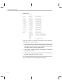
Notational Conventions
This document uses the following conventions:
- The TMS320C62x, ’C64x, and ’C67x core is referred to as TMS320C6000
or C6000.
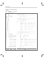
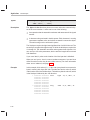
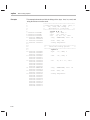
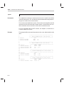
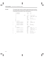
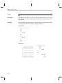
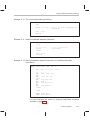
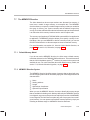
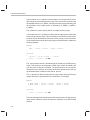
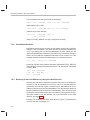
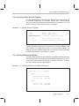
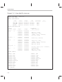
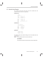
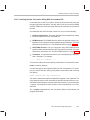
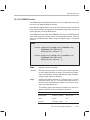
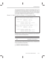
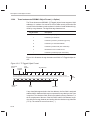
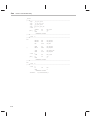
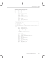
- Program listings, program examples, and interactive displays are shown
in a special typeface. Examples use a bold version of the special typeface for emphasis; interactive displays use a bold version of
the special typeface to distinguish commands that you enter from items
that the system displays (such as prompts, command output, error messages, etc.).
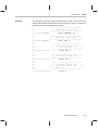
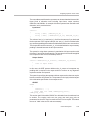
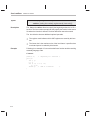
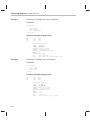
Here is a sample program listing:
1
2
3
4
5
00000000
00000000 0000002F
00000001 00000032
00000000
00000000 010401E0
x
z
.data
.byte
.byte
.text
ADD
47
50
A0,A1,A2
- In syntax descriptions, the instruction, command, or directive is in a bold
typeface and parameters are in an italic typeface. Portions of a syntax that
are in bold should be entered as shown; portions of a syntax that are in
italics describe the type of information that should be entered. Syntax that
is entered on a command line is centered. Syntax that is used in a text file
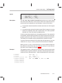
is left justified. Here is an example of command-line syntax:
lnk6x [options] filename1 . ... filenamen
The lnk6x command invokes the linker and has two parameters. The first
parameter, options, is optional (see the next bullet for details). The second
parameter, filename, is required and you can enter more than one.
iv
Notational Conventions
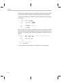
- Square brackets ( [ and ] ) identify an optional parameter. If you use an
optional parameter, you specify the information within the brackets.
Unless the square brackets are in a bold typeface, do not enter the brackets themselves. This is an example of a command that has an optional
parameter:
hex6x [options] filename
The hex6x command has two parameters. The second parameter, filename, is required. The first parameter, options, is optional. Since options
is plural, you can select several options.
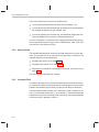
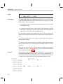
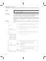
- In assembler syntax statements, column 1 is reserved for the first char-
acter of a label or symbol. If the label or symbol is optional, it is usually not
shown. If it is a required parameter, it is shown starting against the left
margin of the shaded box, as in the example below. No instruction, command, directive, or parameter other than a symbol or label can begin in
column 1.
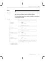
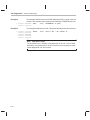
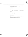
symbol .usect ”section name”, size in bytes [, alignment ]
The symbol is required for the .usect directive and must begin in column 1.
The section name must be enclosed in quotes and the parameter size in
bytes must be separated from the section name by a comma. The alignment is optional and, if used, must be separated by a comma.
- Some directives can have a varying number of parameters. For example,
the .byte directive can have up to 100 parameters. The syntax for this
directive is:
.byte value1 [, ... , valuen ]
This syntax shows that .byte must have at least one value parameter, but
you have the option of supplying additional value parameters, each separated from the previous one by a comma.
Read This First
v
Related
Documentation
Texas
Instruments From Texas Instruments
Notational
Conventions /From
Related
Documentation
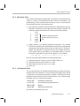
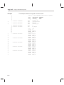
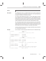
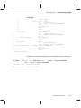
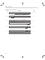
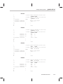
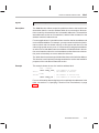
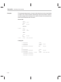
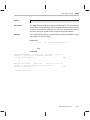
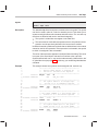
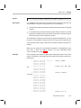
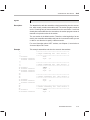
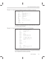
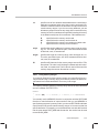
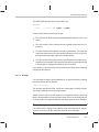
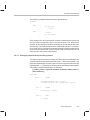
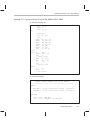
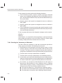
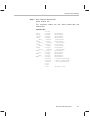
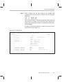
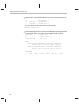
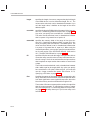
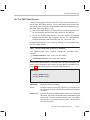
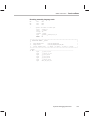
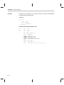
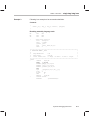
- In program listings and program examples, pipe symbols (||) indicate
parallel instructions, and square brackets ( [ ] ) indicate conditional instructions. This is an example of parallel and conditional instructions:
1
2
3
4
5
6
7
8
9
10
11
.global tab1, tab2
00000000
00000004
00000008
0000000c
00000028!
00000068!
008031A9
010848C0 ||
00000010
00000014
00000018
0000001c
80000212
01003674
0087E1A0
00004000
MVK
MVKH
MVK
ZERO
$1:[A1] B
STW
SUB
NOP
tab1,A0
tab1,A0
99, A1
A2
$1
A2, *A0++
A1,1,A1
3
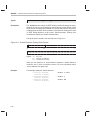
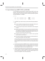
The instruction on line five executes in parallel with instruction on line six.
The instruction on line eight is conditional: the branch to $1 only occurs if
the contents of A1 are not equal to 0.
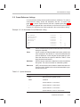
- Following are other symbols and abbreviations used throughout this docu-
ment:
Symbol
Definition
Symbol
Definition
B, b
Suffix — binary integer
MSB
Most significant bit
H, h
Suffix — hexadecimal
integer
0x
Prefix — hexadecimal
integer
LSB
Least significant bit
Q, q
Suffix — octal integer
Related Documentation From Texas Instruments
The following books describe the TMS320C6000 devices and related support
tools. To obtain a copy of any of these TI documents, call the Texas Instruments Literature Response Center at (800) 477–8924. When ordering, please
identify the book by its title and literature number.
TMS320C6000 Optimizing Compiler User’s Guide (literature number
SPRU187) describes the ’C6000 C/C++ compiler and the assembly optimizer. This C/C++ compiler accepts ANSI standard C/C++ source code
and produces assembly language source code for the ’C6000 generation of devices. The assembly optimizer helps you optimize your
assembly code.
Code Composer User’s Guide (literature number SPRU296) explains how to
use the Code Composer development environment to build and debug
embedded real-time DSP applications.
vi
Related Documentation From Texas Instruments / Trademarks
TMS320C6000 Programmer’s Guide (literature number SPRU198)
describes ways to optimize C and assembly code for the TMS320C6000
DSPs and includes application program examples.
TMS320C6000 CPU and Instruction Set Reference Guide (literature
number SPRU189) describes the ’C6000 CPU architecture, instruction
set, pipeline, and interrupts for these digital signal processors.
TMS320C6000 Peripherals Reference Guide (literature number SPRU190)
describes common peripherals available on the TMS320C6000 digital
signal processors. This book includes information on the internal data
and program memories, the external memory interface (EMIF), the host
port interface (HPI), multichannel buffered serial ports (McBSPs), direct
memory access (DMA), enhanced DMA (EDMA), expansion bus, clocking and phase-locked loop (PLL), and the power-down modes.
TMS320C6000 Technical Brief (literature number SPRU197) gives an
introduction to the ’C6000 platform of digital signal processors, development tools, and third-party support.
Trademarks
Windows and Windows NT are trademarks of Microsoft Corporation.
The Texas Instruments logo and Texas Instruments are registered trademarks
of Texas Instruments Incorporated. Trademarks of Texas Instruments include:
TI, XDS, Code Composer, Code Composer Studio, TMS320, TMS320C6000
and 320 Hotline On-line.
All other brand or product names are trademarks or registered trademarks of
their respective companies or organizations.
Read This First
vii
Contents
Contents
1
Introduction to the Software Development Tools . . . . . . . . . . . . . . . . . . . . . . . . . . . . . . . . . . . 1-1
Provides an overview of the software development tools.
1.1
1.2
2
Introduction to Common Object File Format . . . . . . . . . . . . . . . . . . . . . . . . . . . . . . . . . . . . . . . 2-1
Common object file format, or COFF, is the object file format used by the TMS320C6000 tools.
This chapter discusses the basic COFF concept of sections and how they can help you use the
assembler and linker more efficiently. Read this chapter before using the assembler and linker.
2.1
2.2
2.3
2.4
2.5
2.6
2.7
3
Software Development Tools Overview . . . . . . . . . . . . . . . . . . . . . . . . . . . . . . . . . . . . . . . . 1-2
Tools Descriptions . . . . . . . . . . . . . . . . . . . . . . . . . . . . . . . . . . . . . . . . . . . . . . . . . . . . . . . . . . 1-3
Sections . . . . . . . . . . . . . . . . . . . . . . . . . . . . . . . . . . . . . . . . . . . . . . . . . . . . . . . . . . . . . . . . . . . 2-2
How the Assembler Handles Sections . . . . . . . . . . . . . . . . . . . . . . . . . . . . . . . . . . . . . . . . . 2-4
2.2.1 Uninitialized Sections . . . . . . . . . . . . . . . . . . . . . . . . . . . . . . . . . . . . . . . . . . . . . . . . 2-4
2.2.2 Initialized Sections . . . . . . . . . . . . . . . . . . . . . . . . . . . . . . . . . . . . . . . . . . . . . . . . . . . 2-6
2.2.3 Named Sections . . . . . . . . . . . . . . . . . . . . . . . . . . . . . . . . . . . . . . . . . . . . . . . . . . . . . 2-6
2.2.4 Subsections . . . . . . . . . . . . . . . . . . . . . . . . . . . . . . . . . . . . . . . . . . . . . . . . . . . . . . . . 2-7
2.2.5 Section Program Counters . . . . . . . . . . . . . . . . . . . . . . . . . . . . . . . . . . . . . . . . . . . . 2-8
2.2.6 Using Sections Directives . . . . . . . . . . . . . . . . . . . . . . . . . . . . . . . . . . . . . . . . . . . . . 2-8
How the Linker Handles Sections . . . . . . . . . . . . . . . . . . . . . . . . . . . . . . . . . . . . . . . . . . . . 2-11
2.3.1 Default Memory Allocation . . . . . . . . . . . . . . . . . . . . . . . . . . . . . . . . . . . . . . . . . . . 2-12
2.3.2 Placing Sections in the Memory Map . . . . . . . . . . . . . . . . . . . . . . . . . . . . . . . . . . 2-13
Relocation . . . . . . . . . . . . . . . . . . . . . . . . . . . . . . . . . . . . . . . . . . . . . . . . . . . . . . . . . . . . . . . . 2-14
Run-Time Relocation . . . . . . . . . . . . . . . . . . . . . . . . . . . . . . . . . . . . . . . . . . . . . . . . . . . . . . . 2-16
Loading a Program . . . . . . . . . . . . . . . . . . . . . . . . . . . . . . . . . . . . . . . . . . . . . . . . . . . . . . . . 2-17
Symbols in a COFF File . . . . . . . . . . . . . . . . . . . . . . . . . . . . . . . . . . . . . . . . . . . . . . . . . . . . 2-18
2.7.1 External Symbols . . . . . . . . . . . . . . . . . . . . . . . . . . . . . . . . . . . . . . . . . . . . . . . . . . . 2-18
2.7.2 The Symbol Table . . . . . . . . . . . . . . . . . . . . . . . . . . . . . . . . . . . . . . . . . . . . . . . . . . 2-19
Assembler Description . . . . . . . . . . . . . . . . . . . . . . . . . . . . . . . . . . . . . . . . . . . . . . . . . . . . . . . . . . . 3-1
Explains how to invoke the assembler and discusses source statement format, valid constants
and expressions, and assembler output.
3.1
3.2
3.3
3.4
Assembler Overview . . . . . . . . . . . . . . . . . . . . . . . . . . . . . . . . . . . . . . . . . . . . . . . . . . . . . . . .
The Assembler’s Role in the Software Development Flow . . . . . . . . . . . . . . . . . . . . . . . .
Invoking the Assembler . . . . . . . . . . . . . . . . . . . . . . . . . . . . . . . . . . . . . . . . . . . . . . . . . . . . . .
Naming Alternate Directories for Assembler Input . . . . . . . . . . . . . . . . . . . . . . . . . . . . . . .
3.4.1 Using the – i Assembler Option . . . . . . . . . . . . . . . . . . . . . . . . . . . . . . . . . . . . . . . .
3.4.2 Using the C6X_A_DIR or A_DIR Environment Variable . . . . . . . . . . . . . . . . . . .
3-2
3-3
3-4
3-7
3-7
3-8
ix
Contents
3.5
3.6
3.7
3.8
3.9
3.10
3.11
4
Assembler Directives . . . . . . . . . . . . . . . . . . . . . . . . . . . . . . . . . . . . . . . . . . . . . . . . . . . . . . . . . . . . 4-1
Describes the directives according to function and presents the directives in alphabetical order.
4.1
4.2
4.3
4.4
4.5
4.6
4.7
4.8
4.9
4.10
x
Source Statement Format . . . . . . . . . . . . . . . . . . . . . . . . . . . . . . . . . . . . . . . . . . . . . . . . . . . 3-9
3.5.1 Label Field . . . . . . . . . . . . . . . . . . . . . . . . . . . . . . . . . . . . . . . . . . . . . . . . . . . . . . . . 3-10
3.5.2 Mnemonic Field . . . . . . . . . . . . . . . . . . . . . . . . . . . . . . . . . . . . . . . . . . . . . . . . . . . . 3-11
3.5.3 Unit Specifier Field . . . . . . . . . . . . . . . . . . . . . . . . . . . . . . . . . . . . . . . . . . . . . . . . . 3-11
3.5.4 Operand Field . . . . . . . . . . . . . . . . . . . . . . . . . . . . . . . . . . . . . . . . . . . . . . . . . . . . . . 3-12
3.5.5 Comment Field . . . . . . . . . . . . . . . . . . . . . . . . . . . . . . . . . . . . . . . . . . . . . . . . . . . . . 3-12
Constants . . . . . . . . . . . . . . . . . . . . . . . . . . . . . . . . . . . . . . . . . . . . . . . . . . . . . . . . . . . . . . . . 3-13
3.6.1 Binary Integers . . . . . . . . . . . . . . . . . . . . . . . . . . . . . . . . . . . . . . . . . . . . . . . . . . . . . 3-13
3.6.2 Octal Integers . . . . . . . . . . . . . . . . . . . . . . . . . . . . . . . . . . . . . . . . . . . . . . . . . . . . . . 3-13
3.6.3 Decimal Integers . . . . . . . . . . . . . . . . . . . . . . . . . . . . . . . . . . . . . . . . . . . . . . . . . . . 3-14
3.6.4 Hexadecimal Integers . . . . . . . . . . . . . . . . . . . . . . . . . . . . . . . . . . . . . . . . . . . . . . . 3-14
3.6.5 Character Constants . . . . . . . . . . . . . . . . . . . . . . . . . . . . . . . . . . . . . . . . . . . . . . . . 3-14
3.6.6 Assembly-Time Constants . . . . . . . . . . . . . . . . . . . . . . . . . . . . . . . . . . . . . . . . . . . 3-15
Character Strings . . . . . . . . . . . . . . . . . . . . . . . . . . . . . . . . . . . . . . . . . . . . . . . . . . . . . . . . . . 3-16
Symbols . . . . . . . . . . . . . . . . . . . . . . . . . . . . . . . . . . . . . . . . . . . . . . . . . . . . . . . . . . . . . . . . . . 3-17
3.8.1 Labels . . . . . . . . . . . . . . . . . . . . . . . . . . . . . . . . . . . . . . . . . . . . . . . . . . . . . . . . . . . . 3-17
3.8.2 Local Labels . . . . . . . . . . . . . . . . . . . . . . . . . . . . . . . . . . . . . . . . . . . . . . . . . . . . . . . 3-17
3.8.3 Symbolic Constants . . . . . . . . . . . . . . . . . . . . . . . . . . . . . . . . . . . . . . . . . . . . . . . . . 3-20
3.8.4 Defining Symbolic Constants (–ad Option) . . . . . . . . . . . . . . . . . . . . . . . . . . . . . 3-20
3.8.5 Predefined Symbolic Constants . . . . . . . . . . . . . . . . . . . . . . . . . . . . . . . . . . . . . . 3-22
3.8.6 Substitution Symbols . . . . . . . . . . . . . . . . . . . . . . . . . . . . . . . . . . . . . . . . . . . . . . . . 3-23
Expressions . . . . . . . . . . . . . . . . . . . . . . . . . . . . . . . . . . . . . . . . . . . . . . . . . . . . . . . . . . . . . . . 3-25
3.9.1 Operators . . . . . . . . . . . . . . . . . . . . . . . . . . . . . . . . . . . . . . . . . . . . . . . . . . . . . . . . . 3-26
3.9.2 Expression Overflow and Underflow . . . . . . . . . . . . . . . . . . . . . . . . . . . . . . . . . . 3-26
3.9.3 Well-Defined Expressions . . . . . . . . . . . . . . . . . . . . . . . . . . . . . . . . . . . . . . . . . . . 3-27
3.9.4 Conditional Expressions . . . . . . . . . . . . . . . . . . . . . . . . . . . . . . . . . . . . . . . . . . . . . 3-27
3.9.5
Legal Expressions . . . . . . . . . . . . . . . . . . . . . . . . . . . . . . . . . . . . . . . . . . . . . . . . . 3-27
3.9.6 Expression Examples . . . . . . . . . . . . . . . . . . . . . . . . . . . . . . . . . . . . . . . . . . . . . . . 3-28
Source Listings . . . . . . . . . . . . . . . . . . . . . . . . . . . . . . . . . . . . . . . . . . . . . . . . . . . . . . . . . . . . 3-30
Cross-Reference Listings . . . . . . . . . . . . . . . . . . . . . . . . . . . . . . . . . . . . . . . . . . . . . . . . . . . 3-33
Directives Summary . . . . . . . . . . . . . . . . . . . . . . . . . . . . . . . . . . . . . . . . . . . . . . . . . . . . . . . . 4-2
Directives That Define Sections . . . . . . . . . . . . . . . . . . . . . . . . . . . . . . . . . . . . . . . . . . . . . . 4-8
Directives That Initialize Constants . . . . . . . . . . . . . . . . . . . . . . . . . . . . . . . . . . . . . . . . . . . 4-10
Directive That Aligns the Section Program Counter . . . . . . . . . . . . . . . . . . . . . . . . . . . . . 4-13
Directives That Format the Output Listings . . . . . . . . . . . . . . . . . . . . . . . . . . . . . . . . . . . . 4-14
Directives That Reference Other Files . . . . . . . . . . . . . . . . . . . . . . . . . . . . . . . . . . . . . . . . 4-16
Directives That Enable Conditional Assembly . . . . . . . . . . . . . . . . . . . . . . . . . . . . . . . . . 4-17
Directives That Define Symbols at Assembly Time . . . . . . . . . . . . . . . . . . . . . . . . . . . . . 4-18
Miscellaneous Directives . . . . . . . . . . . . . . . . . . . . . . . . . . . . . . . . . . . . . . . . . . . . . . . . . . . 4-20
Directives Reference . . . . . . . . . . . . . . . . . . . . . . . . . . . . . . . . . . . . . . . . . . . . . . . . . . . . . . . 4-21
Contents
5
Macro Language . . . . . . . . . . . . . . . . . . . . . . . . . . . . . . . . . . . . . . . . . . . . . . . . . . . . . . . . . . . . . . . . 5-1
Describes macro directives, substitution symbols used as macro parameters, and how to
create macros.
5.1
5.2
5.3
5.4
5.5
5.6
5.7
5.8
5.9
5.10
6
Archiver Description . . . . . . . . . . . . . . . . . . . . . . . . . . . . . . . . . . . . . . . . . . . . . . . . . . . . . . . . . . . . . 6-1
Describes instructions for invoking the archiver, creating new archive libraries, and modifying
existing libraries.
6.1
6.2
6.3
6.4
7
Using Macros . . . . . . . . . . . . . . . . . . . . . . . . . . . . . . . . . . . . . . . . . . . . . . . . . . . . . . . . . . . . . . 5-2
Defining Macros . . . . . . . . . . . . . . . . . . . . . . . . . . . . . . . . . . . . . . . . . . . . . . . . . . . . . . . . . . . . 5-3
Macro Parameters/Substitution Symbols . . . . . . . . . . . . . . . . . . . . . . . . . . . . . . . . . . . . . . . 5-5
5.3.1 Directives That Define Substitution Symbols . . . . . . . . . . . . . . . . . . . . . . . . . . . . 5-6
5.3.2 Built-In Substitution Symbol Functions . . . . . . . . . . . . . . . . . . . . . . . . . . . . . . . . . 5-7
5.3.3 Recursive Substitution Symbols . . . . . . . . . . . . . . . . . . . . . . . . . . . . . . . . . . . . . . . 5-9
5.3.4 Forced Substitution . . . . . . . . . . . . . . . . . . . . . . . . . . . . . . . . . . . . . . . . . . . . . . . . . . 5-9
5.3.5 Accessing Individual Characters of Subscripted Substitution Symbols . . . . . 5-10
5.3.6 Substitution Symbols as Local Variables in Macros . . . . . . . . . . . . . . . . . . . . . . 5-12
Macro Libraries . . . . . . . . . . . . . . . . . . . . . . . . . . . . . . . . . . . . . . . . . . . . . . . . . . . . . . . . . . . . 5-13
Using Conditional Assembly in Macros . . . . . . . . . . . . . . . . . . . . . . . . . . . . . . . . . . . . . . . 5-14
Using Labels in Macros . . . . . . . . . . . . . . . . . . . . . . . . . . . . . . . . . . . . . . . . . . . . . . . . . . . . . 5-16
Producing Messages in Macros . . . . . . . . . . . . . . . . . . . . . . . . . . . . . . . . . . . . . . . . . . . . . 5-17
Using Directives to Format the Output Listing . . . . . . . . . . . . . . . . . . . . . . . . . . . . . . . . . . 5-19
Using Recursive and Nested Macros . . . . . . . . . . . . . . . . . . . . . . . . . . . . . . . . . . . . . . . . . 5-21
Macro Directives Summary . . . . . . . . . . . . . . . . . . . . . . . . . . . . . . . . . . . . . . . . . . . . . . . . . 5-23
Archiver Overview . . . . . . . . . . . . . . . . . . . . . . . . . . . . . . . . . . . . . . . . . . . . . . . . . . . . . . . . . .
The Archiver’s Role in the Software Development Flow . . . . . . . . . . . . . . . . . . . . . . . . . .
Invoking the Archiver . . . . . . . . . . . . . . . . . . . . . . . . . . . . . . . . . . . . . . . . . . . . . . . . . . . . . . . .
Archiver Examples . . . . . . . . . . . . . . . . . . . . . . . . . . . . . . . . . . . . . . . . . . . . . . . . . . . . . . . . . .
6-2
6-3
6-4
6-6
Linker Description . . . . . . . . . . . . . . . . . . . . . . . . . . . . . . . . . . . . . . . . . . . . . . . . . . . . . . . . . . . . . . . 7-1
Explains how to invoke the linker, provides details about linker operation, discusses linker directives, and presents a detailed linking example.
7.1
7.2
7.3
7.4
Linker Overview . . . . . . . . . . . . . . . . . . . . . . . . . . . . . . . . . . . . . . . . . . . . . . . . . . . . . . . . . . . . 7-2
The Linker’s Role in the Software Development Flow . . . . . . . . . . . . . . . . . . . . . . . . . . . . 7-3
Invoking the Linker . . . . . . . . . . . . . . . . . . . . . . . . . . . . . . . . . . . . . . . . . . . . . . . . . . . . . . . . . . 7-4
Linker Options . . . . . . . . . . . . . . . . . . . . . . . . . . . . . . . . . . . . . . . . . . . . . . . . . . . . . . . . . . . . . 7-5
7.4.1 Relocation Capabilities (– a and – r Options) . . . . . . . . . . . . . . . . . . . . . . . . . . . . . 7-7
7.4.2 Disable Merge of Symbolic Debugging Information (–b Option) . . . . . . . . . . . . 7-8
7.4.3 C Language Options (–c and –cr Options) . . . . . . . . . . . . . . . . . . . . . . . . . . . . . . 7-9
7.4.4 Define an Entry Point (–e global_symbol Option) . . . . . . . . . . . . . . . . . . . . . . . . 7-9
7.4.5 Set Default Fill Value (–f fill_value Option) . . . . . . . . . . . . . . . . . . . . . . . . . . . . . 7-10
7.4.6 Make a Symbol Global (–g symbol Option) . . . . . . . . . . . . . . . . . . . . . . . . . . . . . 7-10
7.4.7 Make All Global Symbols Static (–h Option) . . . . . . . . . . . . . . . . . . . . . . . . . . . . 7-10
7.4.8 Define Heap Size (–heap size Option) . . . . . . . . . . . . . . . . . . . . . . . . . . . . . . . . . 7-11
7.4.9 Alter the Library Search Algorithm (–l Option, –i Option,
and C_DIR/C6X_C_DIR Environment Variables) . . . . . . . . . . . . . . . . . . . . . . . . 7-11
Contents
xi
Contents
7.4.10
7.4.11
7.4.12
7.4.13
7.4.14
7.4.15
7.4.16
7.4.17
7.4.18
7.5
7.6
7.7
7.8
7.9
7.10
7.11
7.12
7.13
xii
Disable Conditional Linking (–j Option) . . . . . . . . . . . . . . . . . . . . . . . . . . . . . . . .
Create a Map File (–m filename Option) . . . . . . . . . . . . . . . . . . . . . . . . . . . . . . .
Name an Output Module (–o Option) . . . . . . . . . . . . . . . . . . . . . . . . . . . . . . . . . .
Specify a Quiet Run (–q Option) . . . . . . . . . . . . . . . . . . . . . . . . . . . . . . . . . . . . . .
Specify an Alternate Search Mechanism for Libraries (-priority Option) . . . .
Strip Symbolic Information (–s Option) . . . . . . . . . . . . . . . . . . . . . . . . . . . . . . . .
Define Stack Size (–stack size Option) . . . . . . . . . . . . . . . . . . . . . . . . . . . . . . . .
Introduce an Unresolved Symbol (–u symbol Option) . . . . . . . . . . . . . . . . . . . .
Display a Message When an Undefined Output Section
Is Created (–w Option) . . . . . . . . . . . . . . . . . . . . . . . . . . . . . . . . . . . . . . . . . . . . . .
7.4.19 Exhaustively Read Libraries (–x Option) . . . . . . . . . . . . . . . . . . . . . . . . . . . . . . .
7.4.20 Suppress MVK Warnings (–xm Option) . . . . . . . . . . . . . . . . . . . . . . . . . . . . . . . .
Linker Command Files . . . . . . . . . . . . . . . . . . . . . . . . . . . . . . . . . . . . . . . . . . . . . . . . . . . . .
7.5.1 Reserved Names in Linker Command Files . . . . . . . . . . . . . . . . . . . . . . . . . . . .
7.5.2 Constants in Linker Command Files . . . . . . . . . . . . . . . . . . . . . . . . . . . . . . . . . .
Object Libraries . . . . . . . . . . . . . . . . . . . . . . . . . . . . . . . . . . . . . . . . . . . . . . . . . . . . . . . . . . .
The MEMORY Directive . . . . . . . . . . . . . . . . . . . . . . . . . . . . . . . . . . . . . . . . . . . . . . . . . . . .
7.7.1 Default Memory Model . . . . . . . . . . . . . . . . . . . . . . . . . . . . . . . . . . . . . . . . . . . . . .
7.7.2 MEMORY Directive Syntax . . . . . . . . . . . . . . . . . . . . . . . . . . . . . . . . . . . . . . . . . .
The SECTIONS Directive . . . . . . . . . . . . . . . . . . . . . . . . . . . . . . . . . . . . . . . . . . . . . . . . . . .
7.8.1 SECTIONS Directive Syntax . . . . . . . . . . . . . . . . . . . . . . . . . . . . . . . . . . . . . . . . .
7.8.2 Allocation . . . . . . . . . . . . . . . . . . . . . . . . . . . . . . . . . . . . . . . . . . . . . . . . . . . . . . . . . .
7.8.3 Specifying Input Sections . . . . . . . . . . . . . . . . . . . . . . . . . . . . . . . . . . . . . . . . . . . .
Specifying a Section’s Run-Time Address . . . . . . . . . . . . . . . . . . . . . . . . . . . . . . . . . . . . .
7.9.1 Specifying Load and Run Addresses . . . . . . . . . . . . . . . . . . . . . . . . . . . . . . . . . .
7.9.2 Uninitialized Sections . . . . . . . . . . . . . . . . . . . . . . . . . . . . . . . . . . . . . . . . . . . . . . .
7.9.3 Referring to the Load Address by Using the .label Directive . . . . . . . . . . . . . .
Using UNION and GROUP Statements . . . . . . . . . . . . . . . . . . . . . . . . . . . . . . . . . . . . . . .
7.10.1 Overlaying Sections With the UNION Statement . . . . . . . . . . . . . . . . . . . . . . . .
7.10.2 Grouping Output Sections Together . . . . . . . . . . . . . . . . . . . . . . . . . . . . . . . . . . .
7.10.3 Nesting UNIONs and GROUPs . . . . . . . . . . . . . . . . . . . . . . . . . . . . . . . . . . . . . . .
7.10.4 Checking the Consistency of Allocators . . . . . . . . . . . . . . . . . . . . . . . . . . . . . . .
Special Section Types (DSECT, COPY, and NOLOAD) . . . . . . . . . . . . . . . . . . . . . . . . .
Default Allocation Algorithm . . . . . . . . . . . . . . . . . . . . . . . . . . . . . . . . . . . . . . . . . . . . . . . . .
7.12.1 How the Allocation Algorithm Creates Output Sections . . . . . . . . . . . . . . . . . .
7.12.2 Reducing Memory Fragmentation . . . . . . . . . . . . . . . . . . . . . . . . . . . . . . . . . . . .
Assigning Symbols at Link Time . . . . . . . . . . . . . . . . . . . . . . . . . . . . . . . . . . . . . . . . . . . . .
7.13.1 Syntax of Assignment Statements . . . . . . . . . . . . . . . . . . . . . . . . . . . . . . . . . . . .
7.13.2 Assigning the SPC to a Symbol . . . . . . . . . . . . . . . . . . . . . . . . . . . . . . . . . . . . . .
7.13.3 Assignment Expressions . . . . . . . . . . . . . . . . . . . . . . . . . . . . . . . . . . . . . . . . . . . .
7.13.4 Symbols Defined by the Linker . . . . . . . . . . . . . . . . . . . . . . . . . . . . . . . . . . . . . . .
7.13.5 Assigning Exact Start, End, and Size Values of a Section to a Symbol . . . . .
7-14
7-14
7-16
7-16
7-16
7-17
7-17
7-18
7-18
7-19
7-19
7-20
7-22
7-22
7-23
7-25
7-25
7-25
7-28
7-28
7-31
7-37
7-40
7-40
7-42
7-42
7-45
7-45
7-47
7-47
7-48
7-50
7-51
7-51
7-52
7-53
7-53
7-54
7-54
7-56
7-57
Contents
7.14
7.15
7.16
7.17
8
7-61
7-61
7-61
7-63
7-64
7-65
7-67
7-67
7-68
7-68
7-69
7-70
7-71
7-72
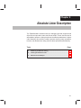
Absolute Lister Description . . . . . . . . . . . . . . . . . . . . . . . . . . . . . . . . . . . . . . . . . . . . . . . . . . . . . . 8-1
Explains how to invoke the absolute lister to obtain a listing of the absolute addresses of an
object file.
8.1
8.2
8.3
9
Creating and Filling Holes . . . . . . . . . . . . . . . . . . . . . . . . . . . . . . . . . . . . . . . . . . . . . . . . . .
7.14.1 Initialized and Uninitialized Sections . . . . . . . . . . . . . . . . . . . . . . . . . . . . . . . . . .
7.14.2 Creating Holes . . . . . . . . . . . . . . . . . . . . . . . . . . . . . . . . . . . . . . . . . . . . . . . . . . . . .
7.14.3 Filling Holes . . . . . . . . . . . . . . . . . . . . . . . . . . . . . . . . . . . . . . . . . . . . . . . . . . . . . . .
7.14.4 Explicit Initialization of Uninitialized Sections . . . . . . . . . . . . . . . . . . . . . . . . . . .
Partial (Incremental) Linking . . . . . . . . . . . . . . . . . . . . . . . . . . . . . . . . . . . . . . . . . . . . . . . .
Linking C/C++ Code . . . . . . . . . . . . . . . . . . . . . . . . . . . . . . . . . . . . . . . . . . . . . . . . . . . . . . .
7.16.1 Run-Time Initialization . . . . . . . . . . . . . . . . . . . . . . . . . . . . . . . . . . . . . . . . . . . . . .
7.16.2 Object Libraries and Run-Time Support . . . . . . . . . . . . . . . . . . . . . . . . . . . . . . .
7.16.3 Setting the Size of the Stack and Heap Sections . . . . . . . . . . . . . . . . . . . . . . . .
7.16.4 Autoinitialization of Variables at Run Time . . . . . . . . . . . . . . . . . . . . . . . . . . . . .
7.16.5 Initialization of Variables at Load Time . . . . . . . . . . . . . . . . . . . . . . . . . . . . . . . . .
7.16.6 The –c and –cr Linker Options . . . . . . . . . . . . . . . . . . . . . . . . . . . . . . . . . . . . . . .
Linker Example . . . . . . . . . . . . . . . . . . . . . . . . . . . . . . . . . . . . . . . . . . . . . . . . . . . . . . . . . . . .
Producing an Absolute Listing . . . . . . . . . . . . . . . . . . . . . . . . . . . . . . . . . . . . . . . . . . . . . . . . 8-2
Invoking the Absolute Lister . . . . . . . . . . . . . . . . . . . . . . . . . . . . . . . . . . . . . . . . . . . . . . . . . . 8-3
Absolute Lister Example . . . . . . . . . . . . . . . . . . . . . . . . . . . . . . . . . . . . . . . . . . . . . . . . . . . . . 8-5
Cross-Reference Lister Description . . . . . . . . . . . . . . . . . . . . . . . . . . . . . . . . . . . . . . . . . . . . . . . 9-1
Explains how to invoke the cross-reference lister to obtain a listing of symbols, their definitions,
and their references in the linked source files.
9.1
9.2
9.3
Producing a Cross-Reference Listing . . . . . . . . . . . . . . . . . . . . . . . . . . . . . . . . . . . . . . . . . . 9-2
Invoking the Cross-Reference Lister . . . . . . . . . . . . . . . . . . . . . . . . . . . . . . . . . . . . . . . . . . 9-3
Cross-Reference Listing Example . . . . . . . . . . . . . . . . . . . . . . . . . . . . . . . . . . . . . . . . . . . . . 9-4
10 Hex Conversion Utility Description . . . . . . . . . . . . . . . . . . . . . . . . . . . . . . . . . . . . . . . . . . . . . . 10-1
Explains how to invoke the hex utility to convert a COFF object file into one of several standard
hexadecimal formats suitable for loading into an EPROM programmer.
10.1
10.2
10.3
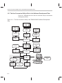
The Hex Conversion Utility’s Role in the Software Development Flow . . . . . . . . . . . . . 10-2
Invoking the Hex Conversion Utility . . . . . . . . . . . . . . . . . . . . . . . . . . . . . . . . . . . . . . . . . . 10-3
10.2.1 Invoking the Hex Conversion Utility From the Command Line . . . . . . . . . . . . 10-3
10.2.2 Invoking the Hex Conversion Utility With a Command File . . . . . . . . . . . . . . . 10-5
Understanding Memory Widths . . . . . . . . . . . . . . . . . . . . . . . . . . . . . . . . . . . . . . . . . . . . . . 10-7
10.3.1 Target Width . . . . . . . . . . . . . . . . . . . . . . . . . . . . . . . . . . . . . . . . . . . . . . . . . . . . . . . 10-8
10.3.2 Specifying the Memory Width . . . . . . . . . . . . . . . . . . . . . . . . . . . . . . . . . . . . . . . . 10-8
10.3.3 Partitioning Data Into Output Files . . . . . . . . . . . . . . . . . . . . . . . . . . . . . . . . . . . . 10-9
10.3.4 Specifying Word Order for Output Words . . . . . . . . . . . . . . . . . . . . . . . . . . . . . 10-12
Contents
xiii
Contents
10.4
The ROMS Directive . . . . . . . . . . . . . . . . . . . . . . . . . . . . . . . . . . . . . . . . . . . . . . . . . . . . . .
10.4.1 When to Use the ROMS Directive . . . . . . . . . . . . . . . . . . . . . . . . . . . . . . . . . . .
10.4.2 An Example of the ROMS Directive . . . . . . . . . . . . . . . . . . . . . . . . . . . . . . . . . .
10.5 The SECTIONS Directive . . . . . . . . . . . . . . . . . . . . . . . . . . . . . . . . . . . . . . . . . . . . . . . . . .
10.6 Assigning Output Filenames . . . . . . . . . . . . . . . . . . . . . . . . . . . . . . . . . . . . . . . . . . . . . . .
10.7 Image Mode and the –fill Option . . . . . . . . . . . . . . . . . . . . . . . . . . . . . . . . . . . . . . . . . . . .
10.7.1 Generating a Memory Image . . . . . . . . . . . . . . . . . . . . . . . . . . . . . . . . . . . . . . . .
10.7.2 Specifying a Fill Value . . . . . . . . . . . . . . . . . . . . . . . . . . . . . . . . . . . . . . . . . . . . . .
10.7.3 Steps to Follow in Using Image Mode . . . . . . . . . . . . . . . . . . . . . . . . . . . . . . . .
10.8 Controlling the ROM Device Address . . . . . . . . . . . . . . . . . . . . . . . . . . . . . . . . . . . . . . . .
10.9 Description of the Object Formats . . . . . . . . . . . . . . . . . . . . . . . . . . . . . . . . . . . . . . . . . . .
10.9.1 ASCII-Hex Object Format (–a Option) . . . . . . . . . . . . . . . . . . . . . . . . . . . . . . . .
10.9.2 Intel MCS-86 Object Format (–i Option) . . . . . . . . . . . . . . . . . . . . . . . . . . . . . .
10.9.3 Motorola Exorciser Object Format (–m Option) . . . . . . . . . . . . . . . . . . . . . . . .
10.9.4 Texas Instruments SDSMAC Object Format (–t Option) . . . . . . . . . . . . . . . . .
10.9.5 Extended Tektronix Object Format (–x Option) . . . . . . . . . . . . . . . . . . . . . . . .
10.10 Hex Conversion Utility Error Messages . . . . . . . . . . . . . . . . . . . . . . . . . . . . . . . . . . . . . .
10-13
10-15
10-16
10-19
10-21
10-23
10-23
10-24
10-24
10-25
10-26
10-27
10-28
10-29
10-30
10-31
10-32
A
Common Object File Format . . . . . . . . . . . . . . . . . . . . . . . . . . . . . . . . . . . . . . . . . . . . . . . . . . . . . . A-1
Contains supplemental technical data about the internal format and structure of COFF object
files.
A.1 COFF File Structure . . . . . . . . . . . . . . . . . . . . . . . . . . . . . . . . . . . . . . . . . . . . . . . . . . . . . . . . A-2
A.2 File Header Structure . . . . . . . . . . . . . . . . . . . . . . . . . . . . . . . . . . . . . . . . . . . . . . . . . . . . . . . A-4
A.3 Optional File Header Format . . . . . . . . . . . . . . . . . . . . . . . . . . . . . . . . . . . . . . . . . . . . . . . . . A-5
A.4 Section Header Structure . . . . . . . . . . . . . . . . . . . . . . . . . . . . . . . . . . . . . . . . . . . . . . . . . . . . A-6
A.5 Structuring Relocation Information . . . . . . . . . . . . . . . . . . . . . . . . . . . . . . . . . . . . . . . . . . . . A-9
A.6 Line Number Table Structure . . . . . . . . . . . . . . . . . . . . . . . . . . . . . . . . . . . . . . . . . . . . . . . . A-12
A.7 Symbol Table Structure and Content . . . . . . . . . . . . . . . . . . . . . . . . . . . . . . . . . . . . . . . . . A-14
A.7.1 Special Symbols . . . . . . . . . . . . . . . . . . . . . . . . . . . . . . . . . . . . . . . . . . . . . . . . . . . A-16
A.7.2 Symbol Name Format . . . . . . . . . . . . . . . . . . . . . . . . . . . . . . . . . . . . . . . . . . . . . . . A-18
A.7.3 String Table Structure . . . . . . . . . . . . . . . . . . . . . . . . . . . . . . . . . . . . . . . . . . . . . . . A-19
A.7.4 Storage Classes . . . . . . . . . . . . . . . . . . . . . . . . . . . . . . . . . . . . . . . . . . . . . . . . . . . . A-20
A.7.5 Symbol Values . . . . . . . . . . . . . . . . . . . . . . . . . . . . . . . . . . . . . . . . . . . . . . . . . . . . . A-21
A.7.6 Section Number . . . . . . . . . . . . . . . . . . . . . . . . . . . . . . . . . . . . . . . . . . . . . . . . . . . . A-22
A.7.7 Type Entry . . . . . . . . . . . . . . . . . . . . . . . . . . . . . . . . . . . . . . . . . . . . . . . . . . . . . . . . . A-22
A.7.8 Auxiliary Entries . . . . . . . . . . . . . . . . . . . . . . . . . . . . . . . . . . . . . . . . . . . . . . . . . . . . A-24
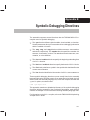
B
Symbolic Debugging Directives . . . . . . . . . . . . . . . . . . . . . . . . . . . . . . . . . . . . . . . . . . . . . . . . . . B-1
Discusses symbolic debugging directives that the TMS320C6000 C compiler uses.
C
Assembler Error Messages . . . . . . . . . . . . . . . . . . . . . . . . . . . . . . . . . . . . . . . . . . . . . . . . . . . . . . . C-1
Lists the error messages that the assembler issues and gives a description of the condition that
caused each error.
D
Linker Error Messages . . . . . . . . . . . . . . . . . . . . . . . . . . . . . . . . . . . . . . . . . . . . . . . . . . . . . . . . . . . D-1
Lists the syntax and command, allocation, and I/O error messages that the linker issues and
gives a description of the condition that causes each error.
E
Glossary . . . . . . . . . . . . . . . . . . . . . . . . . . . . . . . . . . . . . . . . . . . . . . . . . . . . . . . . . . . . . . . . . . . . . . . . E-1
Defines terms and acronyms used in this book.
xiv
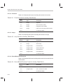
Figures
Figures
1–1
2–1
2–2
2–3
3–1
4–1
4–2
4–3
4–4
4–5
4–6
4–7
4–8
6–1
7–1
7–2
7–3
7–4
7–5
7–6
8–1
8–2
8–3
9–1
10–1
10–2
10–3
10–4
10–5
10–6
10–7
10–8
10–9
10–10
TMS320C6000 Software Development Flow . . . . . . . . . . . . . . . . . . . . . . . . . . . . . . . . . . . . . . 1-2
Partitioning Memory Into Logical Blocks . . . . . . . . . . . . . . . . . . . . . . . . . . . . . . . . . . . . . . . . . . 2-3
Object Code Generated by the File in Example 2–1 . . . . . . . . . . . . . . . . . . . . . . . . . . . . . . 2-10
Combining Input Sections to Form an Executable Object Module . . . . . . . . . . . . . . . . . . . 2-12
The Assembler in the TMS320C6000 Software Development Flow . . . . . . . . . . . . . . . . . . 3-3
The .space and .bes Directives . . . . . . . . . . . . . . . . . . . . . . . . . . . . . . . . . . . . . . . . . . . . . . . . 4-10
The .field Directive . . . . . . . . . . . . . . . . . . . . . . . . . . . . . . . . . . . . . . . . . . . . . . . . . . . . . . . . . . . 4-11
Initialization Directives . . . . . . . . . . . . . . . . . . . . . . . . . . . . . . . . . . . . . . . . . . . . . . . . . . . . . . . . 4-12
The .align Directive . . . . . . . . . . . . . . . . . . . . . . . . . . . . . . . . . . . . . . . . . . . . . . . . . . . . . . . . . . . 4-13
Double-Precision Floating-Point Format . . . . . . . . . . . . . . . . . . . . . . . . . . . . . . . . . . . . . . . . . 4-32
The .field Directive . . . . . . . . . . . . . . . . . . . . . . . . . . . . . . . . . . . . . . . . . . . . . . . . . . . . . . . . . . . 4-40
Single-Precision Floating-Point Format . . . . . . . . . . . . . . . . . . . . . . . . . . . . . . . . . . . . . . . . . . 4-41
The .usect Directive . . . . . . . . . . . . . . . . . . . . . . . . . . . . . . . . . . . . . . . . . . . . . . . . . . . . . . . . . . 4-79
The Archiver in the TMS320C6000 Software Development Flow . . . . . . . . . . . . . . . . . . . . 6-3
The Linker in the TMS320C6000 Software Development Flow . . . . . . . . . . . . . . . . . . . . . . 7-3
Section Allocation Defined by Example 7–4 . . . . . . . . . . . . . . . . . . . . . . . . . . . . . . . . . . . . . . 7-31
Run-Time Execution of Example 7–6 . . . . . . . . . . . . . . . . . . . . . . . . . . . . . . . . . . . . . . . . . . . 7-44
Memory Allocation Shown in Example 7–7 and Example 7–8 . . . . . . . . . . . . . . . . . . . . . . 7-46
Autoinitialization at Run Time . . . . . . . . . . . . . . . . . . . . . . . . . . . . . . . . . . . . . . . . . . . . . . . . . . 7-69
Initialization at Load Time . . . . . . . . . . . . . . . . . . . . . . . . . . . . . . . . . . . . . . . . . . . . . . . . . . . . . 7-70
Absolute Lister Development Flow . . . . . . . . . . . . . . . . . . . . . . . . . . . . . . . . . . . . . . . . . . . . . . 8-2
module1.lst . . . . . . . . . . . . . . . . . . . . . . . . . . . . . . . . . . . . . . . . . . . . . . . . . . . . . . . . . . . . . . . . . . . 8-9
module2.lst . . . . . . . . . . . . . . . . . . . . . . . . . . . . . . . . . . . . . . . . . . . . . . . . . . . . . . . . . . . . . . . . . . 8-10
The Cross-Reference Lister in the TMS320C6000 Software Development Flow . . . . . . . 9-2
The Hex Conversion Utility in the TMS320C6000 Software Development Flow . . . . . . . 10-2
Hex Conversion Utility Process Flow . . . . . . . . . . . . . . . . . . . . . . . . . . . . . . . . . . . . . . . . . . . . 10-7
COFF Data and Memory Widths . . . . . . . . . . . . . . . . . . . . . . . . . . . . . . . . . . . . . . . . . . . . . . . 10-9
Data, Memory, and ROM Widths . . . . . . . . . . . . . . . . . . . . . . . . . . . . . . . . . . . . . . . . . . . . . . 10-11
The infile.out File Partitioned Into Four Output Files . . . . . . . . . . . . . . . . . . . . . . . . . . . . . 10-16
ASCII-Hex Object Format . . . . . . . . . . . . . . . . . . . . . . . . . . . . . . . . . . . . . . . . . . . . . . . . . . . . 10-27
Intel Hexadecimal Object Format . . . . . . . . . . . . . . . . . . . . . . . . . . . . . . . . . . . . . . . . . . . . . . 10-28
Motorola-S Format . . . . . . . . . . . . . . . . . . . . . . . . . . . . . . . . . . . . . . . . . . . . . . . . . . . . . . . . . . 10-29
TI-Tagged Object Format . . . . . . . . . . . . . . . . . . . . . . . . . . . . . . . . . . . . . . . . . . . . . . . . . . . . . 10-30
Extended Tektronix Object Format . . . . . . . . . . . . . . . . . . . . . . . . . . . . . . . . . . . . . . . . . . . . . 10-31
Contents
xv
Figures
A–1
A–2
A–3
A–4
A–5
A–6
A–7
A–8
A–9
A–10
xvi
COFF File Structure . . . . . . . . . . . . . . . . . . . . . . . . . . . . . . . . . . . . . . . . . . . . . . . . . . . . . . . . . . . A-2
Sample COFF Object File . . . . . . . . . . . . . . . . . . . . . . . . . . . . . . . . . . . . . . . . . . . . . . . . . . . . . . A-3
Section Header Pointers for the .text Section . . . . . . . . . . . . . . . . . . . . . . . . . . . . . . . . . . . . . A-8
Line Number Blocks . . . . . . . . . . . . . . . . . . . . . . . . . . . . . . . . . . . . . . . . . . . . . . . . . . . . . . . . . . A-12
Line Number Entries . . . . . . . . . . . . . . . . . . . . . . . . . . . . . . . . . . . . . . . . . . . . . . . . . . . . . . . . . . A-13
Symbol Table Contents . . . . . . . . . . . . . . . . . . . . . . . . . . . . . . . . . . . . . . . . . . . . . . . . . . . . . . . A-14
Symbols for Blocks . . . . . . . . . . . . . . . . . . . . . . . . . . . . . . . . . . . . . . . . . . . . . . . . . . . . . . . . . . . A-17
Symbols for Functions . . . . . . . . . . . . . . . . . . . . . . . . . . . . . . . . . . . . . . . . . . . . . . . . . . . . . . . . A-18
Symbols for Functions That Return a Structure or Union . . . . . . . . . . . . . . . . . . . . . . . . . . A-18
String Table Entries for Sample Symbol Names . . . . . . . . . . . . . . . . . . . . . . . . . . . . . . . . . . A-19
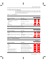
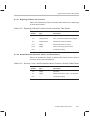
Tables
Tables
3–1
3–2
4–1
5–1
5–2
5–3
5–4
5–5
5–6
7–1
7–2
9–1
10–1
10–2
A–1
A–2
A–3
A–4
A–5
A–6
A–7
A–8
A–9
A–10
A–11
A–12
A–13
A–14
A–15
A–16
A–17
A–18
A–19
A–20
A–21
A–22
A–23
A–24
A–25
Operators Used in Expressions (Precedence) . . . . . . . . . . . . . . . . . . . . . . . . . . . . . . . . . . . . 3-26
Symbol Attributes . . . . . . . . . . . . . . . . . . . . . . . . . . . . . . . . . . . . . . . . . . . . . . . . . . . . . . . . . . . . 3-33
Assembler Directives Summary . . . . . . . . . . . . . . . . . . . . . . . . . . . . . . . . . . . . . . . . . . . . . . . . . 4-2
Substitution Symbol Functions and Return Values . . . . . . . . . . . . . . . . . . . . . . . . . . . . . . . . . 5-8
Creating Macros . . . . . . . . . . . . . . . . . . . . . . . . . . . . . . . . . . . . . . . . . . . . . . . . . . . . . . . . . . . . . 5-23
Manipulating Substitution Symbols . . . . . . . . . . . . . . . . . . . . . . . . . . . . . . . . . . . . . . . . . . . . . 5-23
Conditional Assembly . . . . . . . . . . . . . . . . . . . . . . . . . . . . . . . . . . . . . . . . . . . . . . . . . . . . . . . . . 5-23
Producing Assembly-Time Messages . . . . . . . . . . . . . . . . . . . . . . . . . . . . . . . . . . . . . . . . . . . 5-24
Formatting the Listing . . . . . . . . . . . . . . . . . . . . . . . . . . . . . . . . . . . . . . . . . . . . . . . . . . . . . . . . . 5-24
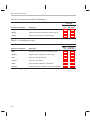
Linker Options Summary . . . . . . . . . . . . . . . . . . . . . . . . . . . . . . . . . . . . . . . . . . . . . . . . . . . . . . . 7-6
Groups of Operators Used in Expressions (Precedence) . . . . . . . . . . . . . . . . . . . . . . . . . . 7-55
Symbol Attributes in Cross-Reference Listing . . . . . . . . . . . . . . . . . . . . . . . . . . . . . . . . . . . . . 9-5
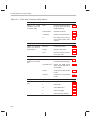
Basic Hex Conversion Utility Options . . . . . . . . . . . . . . . . . . . . . . . . . . . . . . . . . . . . . . . . . . . 10-4
Options for Specifying Hex Conversion Formats . . . . . . . . . . . . . . . . . . . . . . . . . . . . . . . . . 10-26
File Header Contents . . . . . . . . . . . . . . . . . . . . . . . . . . . . . . . . . . . . . . . . . . . . . . . . . . . . . . . . . . A-4
File Header Flags (Bytes 18 and 19) . . . . . . . . . . . . . . . . . . . . . . . . . . . . . . . . . . . . . . . . . . . . . A-4
Optional File Header Contents . . . . . . . . . . . . . . . . . . . . . . . . . . . . . . . . . . . . . . . . . . . . . . . . . . A-5
Section Header Contents . . . . . . . . . . . . . . . . . . . . . . . . . . . . . . . . . . . . . . . . . . . . . . . . . . . . . . A-6
Section Header Flags (Bytes 40 Through 43) . . . . . . . . . . . . . . . . . . . . . . . . . . . . . . . . . . . . . A-7
Relocation Entry Contents . . . . . . . . . . . . . . . . . . . . . . . . . . . . . . . . . . . . . . . . . . . . . . . . . . . . . . A-9
Relocation Types (Bytes 8 and 9) . . . . . . . . . . . . . . . . . . . . . . . . . . . . . . . . . . . . . . . . . . . . . . A-10
Line Number Entry Format . . . . . . . . . . . . . . . . . . . . . . . . . . . . . . . . . . . . . . . . . . . . . . . . . . . . A-12
Symbol Table Entry Contents . . . . . . . . . . . . . . . . . . . . . . . . . . . . . . . . . . . . . . . . . . . . . . . . . . A-15
Special Symbols in the Symbol Table . . . . . . . . . . . . . . . . . . . . . . . . . . . . . . . . . . . . . . . . . . . A-16
Symbol Storage Classes . . . . . . . . . . . . . . . . . . . . . . . . . . . . . . . . . . . . . . . . . . . . . . . . . . . . . . A-20
Special Symbols and Their Storage Classes . . . . . . . . . . . . . . . . . . . . . . . . . . . . . . . . . . . . . A-21
Symbol Values and Storage Classes . . . . . . . . . . . . . . . . . . . . . . . . . . . . . . . . . . . . . . . . . . . A-21
Section Numbers . . . . . . . . . . . . . . . . . . . . . . . . . . . . . . . . . . . . . . . . . . . . . . . . . . . . . . . . . . . . A-22
Basic Types . . . . . . . . . . . . . . . . . . . . . . . . . . . . . . . . . . . . . . . . . . . . . . . . . . . . . . . . . . . . . . . . . A-23
Derived Types . . . . . . . . . . . . . . . . . . . . . . . . . . . . . . . . . . . . . . . . . . . . . . . . . . . . . . . . . . . . . . . A-23
Auxiliary Symbol Table Entries Format . . . . . . . . . . . . . . . . . . . . . . . . . . . . . . . . . . . . . . . . . . A-24
Section Format for Auxiliary Table Entries . . . . . . . . . . . . . . . . . . . . . . . . . . . . . . . . . . . . . . . A-25
Tag Name Format for Auxiliary Table Entries . . . . . . . . . . . . . . . . . . . . . . . . . . . . . . . . . . . . . A-25
End-of-Structure Format for Auxiliary Table Entries . . . . . . . . . . . . . . . . . . . . . . . . . . . . . . . A-25
Function Format for Auxiliary Table Entries . . . . . . . . . . . . . . . . . . . . . . . . . . . . . . . . . . . . . . A-26
Array Format for Auxiliary Table Entries . . . . . . . . . . . . . . . . . . . . . . . . . . . . . . . . . . . . . . . . . A-26
End-of-Blocks/Functions Format for Auxiliary Table Entries . . . . . . . . . . . . . . . . . . . . . . . . A-26
Beginning-of-Blocks/Functions Format for Auxiliary Table Entries . . . . . . . . . . . . . . . . . . . A-27
Structure, Union, and Enumeration Names Format for Auxiliary Table Entries . . . . . . . . A-27
Contents
xvii
Examples
Examples
2–1
2–2
2–3
3–1
3–2
3–3
3–4
3–5
4–1
5–1
5–2
5–3
5–4
5–5
5–6
5–7
5–8
5–9
5–10
5–11
5–12
5–13
5–14
5–15
5–16
7–1
7–2
7–3
7–4
7–5
7–6
7–7
7–8
7–9
7–10
7–11
7–12
7–13
9–1
10–1
10–2
xviii
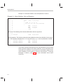
Using Sections Directives . . . . . . . . . . . . . . . . . . . . . . . . . . . . . . . . . . . . . . . . . . . . . . . . . . . . . . 2-9
Code That Generates Relocation Entries . . . . . . . . . . . . . . . . . . . . . . . . . . . . . . . . . . . . . . . . 2-14
Simple Assembler Listing . . . . . . . . . . . . . . . . . . . . . . . . . . . . . . . . . . . . . . . . . . . . . . . . . . . . . 2-15
Local Labels of the Form $n . . . . . . . . . . . . . . . . . . . . . . . . . . . . . . . . . . . . . . . . . . . . . . . . . . . 3-18
Local Labels of the Form name? . . . . . . . . . . . . . . . . . . . . . . . . . . . . . . . . . . . . . . . . . . . . . . . 3-19
Using Symbolic Constants Defined on Command Line . . . . . . . . . . . . . . . . . . . . . . . . . . . . 3-21
Assembler Listing . . . . . . . . . . . . . . . . . . . . . . . . . . . . . . . . . . . . . . . . . . . . . . . . . . . . . . . . . . . . 3-32
An Assembler Cross-Reference Listing . . . . . . . . . . . . . . . . . . . . . . . . . . . . . . . . . . . . . . . . . 3-33
Sections Directives . . . . . . . . . . . . . . . . . . . . . . . . . . . . . . . . . . . . . . . . . . . . . . . . . . . . . . . . . . . . 4-9
Macro Definition, Call, and Expansion . . . . . . . . . . . . . . . . . . . . . . . . . . . . . . . . . . . . . . . . . . . 5-4
Calling a Macro With Varying Numbers of Arguments . . . . . . . . . . . . . . . . . . . . . . . . . . . . . . 5-6
The .asg Directive . . . . . . . . . . . . . . . . . . . . . . . . . . . . . . . . . . . . . . . . . . . . . . . . . . . . . . . . . . . . . 5-6
The .eval Directive . . . . . . . . . . . . . . . . . . . . . . . . . . . . . . . . . . . . . . . . . . . . . . . . . . . . . . . . . . . . 5-7
Using Built-In Substitution Symbol Functions . . . . . . . . . . . . . . . . . . . . . . . . . . . . . . . . . . . . . 5-8
Recursive Substitution . . . . . . . . . . . . . . . . . . . . . . . . . . . . . . . . . . . . . . . . . . . . . . . . . . . . . . . . . 5-9
Using the Forced Substitution Operator . . . . . . . . . . . . . . . . . . . . . . . . . . . . . . . . . . . . . . . . . 5-10
Using Subscripted Substitution Symbols to Redefine an Instruction . . . . . . . . . . . . . . . . . 5-11
Using Subscripted Substitution Symbols to Find Substrings . . . . . . . . . . . . . . . . . . . . . . . . 5-11
The .loop/.break/.endloop Directives . . . . . . . . . . . . . . . . . . . . . . . . . . . . . . . . . . . . . . . . . . . . 5-15
Nested Conditional Assembly Directives . . . . . . . . . . . . . . . . . . . . . . . . . . . . . . . . . . . . . . . . 5-15
Built-In Substitution Symbol Functions in a Conditional Assembly Code Block . . . . . . . 5-15
Unique Labels in a Macro . . . . . . . . . . . . . . . . . . . . . . . . . . . . . . . . . . . . . . . . . . . . . . . . . . . . . 5-16
Producing Messages in a Macro . . . . . . . . . . . . . . . . . . . . . . . . . . . . . . . . . . . . . . . . . . . . . . . 5-18
Using Nested Macros . . . . . . . . . . . . . . . . . . . . . . . . . . . . . . . . . . . . . . . . . . . . . . . . . . . . . . . . . 5-21
Using Recursive Macros . . . . . . . . . . . . . . . . . . . . . . . . . . . . . . . . . . . . . . . . . . . . . . . . . . . . . . 5-22
Linker Command File . . . . . . . . . . . . . . . . . . . . . . . . . . . . . . . . . . . . . . . . . . . . . . . . . . . . . . . . . 7-20
Command File With Linker Directives . . . . . . . . . . . . . . . . . . . . . . . . . . . . . . . . . . . . . . . . . . . 7-21
The MEMORY Directive . . . . . . . . . . . . . . . . . . . . . . . . . . . . . . . . . . . . . . . . . . . . . . . . . . . . . . 7-26
The SECTIONS Directive . . . . . . . . . . . . . . . . . . . . . . . . . . . . . . . . . . . . . . . . . . . . . . . . . . . . . 7-30
The Most Common Method of Specifying Section Contents . . . . . . . . . . . . . . . . . . . . . . . . 7-37
Copying a Section From SLOW_MEM to FAST_MEM . . . . . . . . . . . . . . . . . . . . . . . . . . . . . 7-43
The UNION Statement . . . . . . . . . . . . . . . . . . . . . . . . . . . . . . . . . . . . . . . . . . . . . . . . . . . . . . . . 7-45
Separate Load Addresses for UNION Sections . . . . . . . . . . . . . . . . . . . . . . . . . . . . . . . . . . . 7-45
Allocate Sections Together . . . . . . . . . . . . . . . . . . . . . . . . . . . . . . . . . . . . . . . . . . . . . . . . . . . . 7-47
Nesting GROUP and UNION Statements . . . . . . . . . . . . . . . . . . . . . . . . . . . . . . . . . . . . . . . . 7-47
Default Allocation for TMS320C6000 Devices . . . . . . . . . . . . . . . . . . . . . . . . . . . . . . . . . . . . 7-51
Linker Command File, demo.cmd . . . . . . . . . . . . . . . . . . . . . . . . . . . . . . . . . . . . . . . . . . . . . . 7-73
Output Map File, demo.map . . . . . . . . . . . . . . . . . . . . . . . . . . . . . . . . . . . . . . . . . . . . . . . . . . . 7-74
Cross-Reference Listing . . . . . . . . . . . . . . . . . . . . . . . . . . . . . . . . . . . . . . . . . . . . . . . . . . . . . . . 9-4
A ROMS Directive Example . . . . . . . . . . . . . . . . . . . . . . . . . . . . . . . . . . . . . . . . . . . . . . . . . . 10-16
Map File Output From Example 10–1 Showing Memory Ranges . . . . . . . . . . . . . . . . . . 10-17
Notes
Notes
Default Sections Directive . . . . . . . . . . . . . . . . . . . . . . . . . . . . . . . . . . . . . . . . . . . . . . . . . . . . . . . . . . . . . 2-4
Expression Can Not Be Larger Than Space Reserved . . . . . . . . . . . . . . . . . . . . . . . . . . . . . . . . . . . 2-15
Labels and Comments in Not Shown Syntaxes . . . . . . . . . . . . . . . . . . . . . . . . . . . . . . . . . . . . . . . . . . . 4-2
Directives That Initialize Constants When Used in a .struct /.endstruct Sequence . . . . . . . . . . . . 4-11
Ending a Macro . . . . . . . . . . . . . . . . . . . . . . . . . . . . . . . . . . . . . . . . . . . . . . . . . . . . . . . . . . . . . . . . . . . . . 4-36
Data Size of longs . . . . . . . . . . . . . . . . . . . . . . . . . . . . . . . . . . . . . . . . . . . . . . . . . . . . . . . . . . . . . . . . . . . 4-48
Directives That Can Appear in a .struct /.endstruct Sequence . . . . . . . . . . . . . . . . . . . . . . . . . . . . . . 4-69
Naming Library Members . . . . . . . . . . . . . . . . . . . . . . . . . . . . . . . . . . . . . . . . . . . . . . . . . . . . . . . . . . . . . . 6-5
The – a and – r Options . . . . . . . . . . . . . . . . . . . . . . . . . . . . . . . . . . . . . . . . . . . . . . . . . . . . . . . . . . . . . . . . 7-7
Filling Memory Ranges . . . . . . . . . . . . . . . . . . . . . . . . . . . . . . . . . . . . . . . . . . . . . . . . . . . . . . . . . . . . . . . 7-27
Binding is Incompatible With Alignment and Named Memory . . . . . . . . . . . . . . . . . . . . . . . . . . . . . . 7-35
Linker Command File Operator Equivalencies . . . . . . . . . . . . . . . . . . . . . . . . . . . . . . . . . . . . . . . . . . . 7-58
Filling Sections . . . . . . . . . . . . . . . . . . . . . . . . . . . . . . . . . . . . . . . . . . . . . . . . . . . . . . . . . . . . . . . . . . . . . . 7-64
The TI-Tagged Format Is 16 Bits Wide . . . . . . . . . . . . . . . . . . . . . . . . . . . . . . . . . . . . . . . . . . . . . . . . 10-10
When the –order Option Applies . . . . . . . . . . . . . . . . . . . . . . . . . . . . . . . . . . . . . . . . . . . . . . . . . . . . . . 10-12
Sections Generated by the C/C++ Compiler . . . . . . . . . . . . . . . . . . . . . . . . . . . . . . . . . . . . . . . . . . . 10-19
Defining the Ranges of Target Memory . . . . . . . . . . . . . . . . . . . . . . . . . . . . . . . . . . . . . . . . . . . . . . . . 10-23
Contents
xix
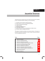
Chapter 1
Introduction to the
Software Development Tools
The TMS320C6000 is supported by a set of software development tools,
which includes an optimizing C/C++ compiler, an assembly optimizer, an assembler, a linker, and assorted utilities. This chapter provides an overview of
these tools.
The TMS320C6000 is supported by the following assembly language development tools:
-
Assembler
Archiver
Linker
Absolute lister
Cross-reference lister
Hex conversion utility
This chapter shows how these tools fit into the general software tools development flow and gives a brief description of each tool. For convenience, it also
summarizes the C/C++ compiler and debugging tools. For detailed information on the compiler and debugger, and for complete descriptions of the
TMS320C6000, refer to books listed in Related Documentation From Texas
Instruments on page vi.
Topic
Page
1.1
Software Development Tools Overview . . . . . . . . . . . . . . . . . . . . . . . . . 1-2
1.2
Tools Descriptions . . . . . . . . . . . . . . . . . . . . . . . . . . . . . . . . . . . . . . . . . . . . 1-3
Introduction to the Software Development Tools
1-1
Software Development Tools Overview
1.1
Software Development Tools Overview
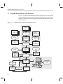
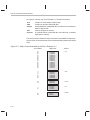
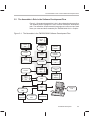
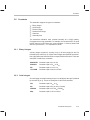
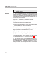
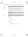
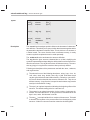
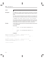
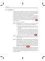
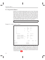
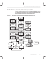
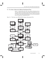
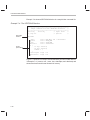
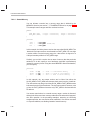
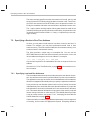
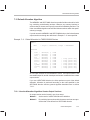
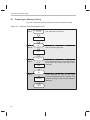
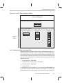
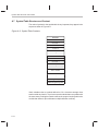
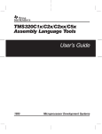
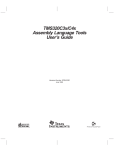
Figure 1–1 shows the TMS320C6000 software development flow. The shaded
portion highlights the most common development path; the other portions are
optional. The other portions are peripheral functions that enhance the development process.
Figure 1–1. TMS320C6000 Software Development Flow
C/C++
source
files
Macro
source
files
Archiver
C/C++
compiler
Linear
assembly
Assembler
source
Assembly
optimizer
Macro
library
Assembler
Archiver
Library of
object
files
1-2
Linker
Executable
COFF
file
Hex conversion
utility
EPROM
programmer
COFF
object
files
Cross-reference
lister
TMS320C6000
Assemblyoptimized
file
Library-build
utility
Run-timesupport
library
Debugging
tools
Tools Descriptions
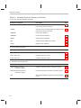
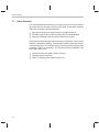
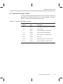
1.2 Tools Descriptions
The following list describes the tools that are shown in Figure 1–1:
- The assembly optimizer allows you to write linear assembly code without
being concerned with the pipeline structure or with assigning registers. It
assigns registers and uses loop optimization to turn linear assembly into
highly parallel assembly that takes advantage of software pipelining.
See the TMS320C6000 Optimizing Compiler User’s Guide for more information.
- The C/C++ compiler accepts C/C++ source code and produces
TMS320C6000 assembly language source code. A shell program, an
optimizer, and an interlist utility are included in the compiler package:
J
The shell program enables you to compile, assemble, and link source
modules in one step.
J
The optimizer modifies code to improve the efficiency of C/C++ programs.
J
The interlist utility interlists C/C++ source statements with assembly
language output to correlate code produced by the compiler with your
source code.
See the TMS320C6000 Optimizing Compiler User’s Guide for more information.
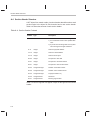
- The assembler translates assembly language source files into machine
language COFF object files. Source files can contain instructions, assembler directives, and macro directives. You can use assembler directives to
control various aspects of the assembly process, such as the source listing format, data alignment, and section content. See Chapter 3, Assembler Description, through Chapter 5, Macro Language, for more information. See the TMS320C62x/64x/67x CPU and Instruction Set Reference
Guide for detailed information on the assembly language instruction set.
- The linker combines object files into a single executable COFF object
module. As it creates the executable module, it performs relocation and
resolves external references. The linker accepts relocatable COFF object
files (created by the assembler) as input. It also accepts archiver library
members and output modules created by a previous linker run. Linker directives allow you to combine object file sections, bind sections or symbols
to addresses or within memory ranges, and define or redefine global symbols. See Chapter 7, Linker Description, for more information.
Introduction to the Software Development Tools
1-3
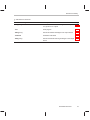
Tools Descriptions
- The archiver allows you to collect a group of files into a single archive file,
called a library. For example, you can collect several macros into a macro
library. The assembler searches the library and uses the members that are
called as macros by the source file. You can also use the archiver to collect
a group of object files into an object library. The linker includes in the library
the members that resolve external references during the link. The archiver
allows you to modify a library by deleting, replacing, extracting, or adding
members. See Chapter 6, Archiver Description, for more information.
- You can use the library-build utility to build your own customized run-
time-support library. See the TMS320C6000 Optimizing Compiler User’s
Guide for more information.
- The hex conversion utility converts a COFF object file into TI-Tagged,
ASCII-Hex, Intel, Motorola-S, or Tektronix object format. The converted file can be downloaded to an EPROM programmer. See Chapter
10, Hex Conversion Utility Description, for more information.
- The cross-reference lister uses object files to produce a cross-reference
listing showing symbols, their definition, and their references in the linked
source files. See Chapter 9, Cross-Reference Lister Description, for more
information.
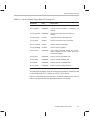
- The main product of this development process is a module that can be
executed in a TMS320C6000 device. You can use one of several debugging tools to refine and correct your code. Available products include:
J
J
An instruction-accurate and clock-accurate software simulator
An XDS emulator
For information about these debugging tools, see the TMS320C6000 C
Source Debugger User’s Guide.
1-4
Chapter 2
Introduction to Common Object File Format
The assembler and linker create object files that can be executed by a
TMS320C6000 device. The format for these object files is called common
object file format (COFF).
COFF makes modular programming easier because it encourages you to
think in terms of blocks of code and data when you write an assembly language
program. These blocks are known as sections. Both the assembler and the
linker provide directives that allow you to create and manipulate sections.
This chapter focuses on the concept and use of sections in assembly language
programs. See Appendix A, Common Object File Format, for details about
COFF object file structure.
Topic
Page
2.1
Sections . . . . . . . . . . . . . . . . . . . . . . . . . . . . . . . . . . . . . . . . . . . . . . . . . . . . . 2-2
2.2
How the Assembler Handles Sections . . . . . . . . . . . . . . . . . . . . . . . . . . 2-4
2.3
How the Linker Handles Sections . . . . . . . . . . . . . . . . . . . . . . . . . . . . . 2-11
2.4
Relocation . . . . . . . . . . . . . . . . . . . . . . . . . . . . . . . . . . . . . . . . . . . . . . . . . . . 2-14
2.5
Run-Time Relocation . . . . . . . . . . . . . . . . . . . . . . . . . . . . . . . . . . . . . . . . . 2-16
2.6
Loading a Program . . . . . . . . . . . . . . . . . . . . . . . . . . . . . . . . . . . . . . . . . . . 2-17
2.7
Symbols in a COFF File . . . . . . . . . . . . . . . . . . . . . . . . . . . . . . . . . . . . . . . 2-18
Introduction to Common Object File Format
2-1
Sections
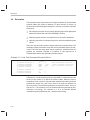
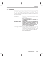
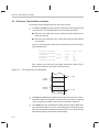
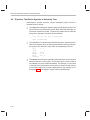
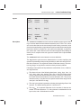
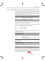
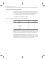
2.1 Sections
The smallest unit of an object file is called a section. A section is a block of code
or data that occupies contiguous space in the memory map with other sections. Each section of an object file is separate and distinct. COFF object files
always contain three default sections:
.text section
usually contains executable code
.data section
usually contains initialized data
.bss section
usually reserves space for uninitialized variables
In addition, the assembler and linker allow you to create, name, and link named
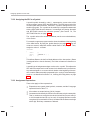
sections that are used like the .data, .text, and .bss sections.
There are two basic types of sections:
Initialized sections
contain data or code. The .text and .data sections
are initialized; named sections created with the
.sect assembler directive are also initialized.
Uninitialized sections
reserve space in the memory map for uninitialized
data. The .bss section is uninitialized; named sections created with the .usect assembler directive are
also uninitialized.
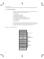
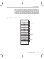
Several assembler directives allow you to associate various portions of code
and data with the appropriate sections. The assembler builds these sections
during the assembly process, creating an object file organized as shown in
Figure 2–1.
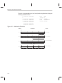
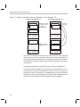
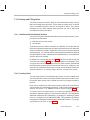
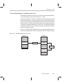
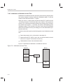
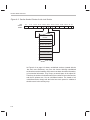
One of the linker’s functions is to relocate sections into the target system’s
memory map; this function is called allocation. Because most systems contain
several types of memory, using sections can help you use target memory more
efficiently. All sections are independently relocatable; you can place any
section into any allocated block of target memory. For example, you can define
a section that contains an initialization routine and then allocate the routine into
a portion of the memory map that contains ROM.
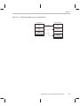
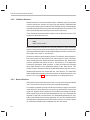
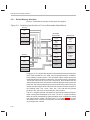
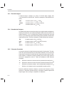
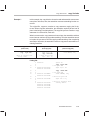
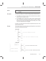
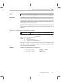
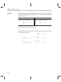
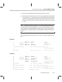
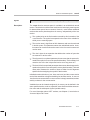
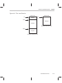
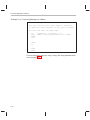
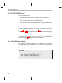
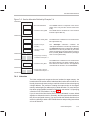
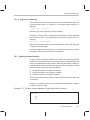
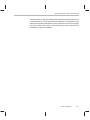
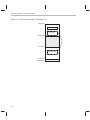
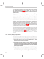
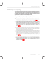
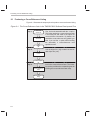
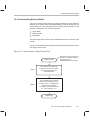
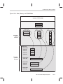
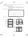
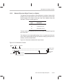
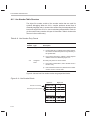
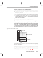
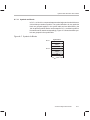
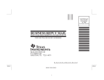
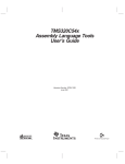
Figure 2–1 shows the relationship between sections in an object file and a
hypothetical target memory.
2-2
Sections
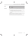
Figure 2–1. Partitioning Memory Into Logical Blocks
Object file
Target memory
.bss
RAM
.data
EEPROM
.text
ROM
Introduction to Common Object File Format
2-3
How the Assembler Handles Sections
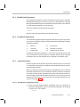
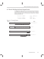
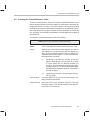
2.2
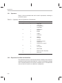
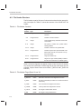
How the Assembler Handles Sections
The assembler identifies the portions of an assembly language program that
belong in a given section. The assembler has five directives that support this
function:
-
.bss
.usect
.text
.data
.sect
The .bss and .usect directives create uninitialized sections; the .text, .data,
and .sect directives create initialized sections.
You can create subsections of any section to give you tighter control of the
memory map. Subsections are created using the .sect and .usect directives.
Subsections are identified with the base section name and a subsection name
separated by a colon. See section 2.2.4, Subsections, on page 2-7, for more
information.
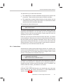
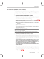
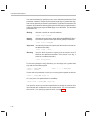
Note: Default Sections Directive
If you do not use any of the sections directives, the assembler assembles
everything into the .text section.
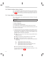
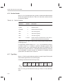
2.2.1
Uninitialized Sections
Uninitialized sections reserve space in TMS320C6000 memory; they are usually allocated into RAM. These sections have no actual contents in the object
file; they simply reserve memory. A program can use this space at run-time for
creating and storing variables.
Uninitialized data areas are built by using the .bss and .usect assembler directives.
- The .bss directive reserves space in the .bss section.
- The .usect directive reserves space in a specific uninitialized named sec-
tion.
Each time you invoke the .bss or .usect directive, the assembler reserves additional space in the .bss or the named section.
2-4
How the Assembler Handles Sections
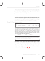
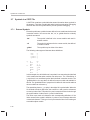
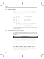
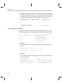
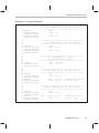
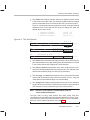
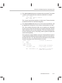
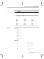
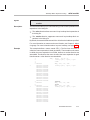
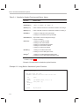
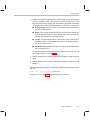
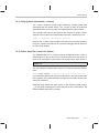
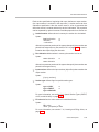
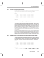
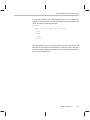
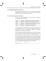
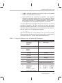
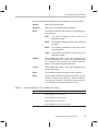
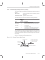
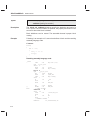
The syntaxes for these directives are:
.bss symbol, size in bytes [, alignment [, bank offset ] ]
symbol .usect “section name”, size in bytes [, alignment [, bank offset ] ]
symbol
points to the first byte reserved by this invocation of the .bss
or .usect directive. The symbol corresponds to the name of
the variable that you are reserving space for. It can be referenced by any other section and can also be declared as a
global symbol (with the .global assembler directive).
size in bytes
is an absolute expression.
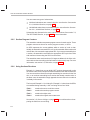
- The .bss directive reserves size in bytes bytes in the
.bss section. You must specify a size; there is no default
value.
- The .usect directive reserves size in bytes bytes in sec-
tion name. You must specify a size; there is no default
value.
alignment
is an optional parameter. It specifies the minimum alignment in bytes required by the space allocated. The default
value is byte aligned. The value must be power of 2.
bank offset
is an optional parameter. It ensures that the space allocated
to the symbol occurs on a specific memory bank boundary.
The bank offset measures the number of bytes to offset
from the alignment specified before assigning the symbol
to that location.
section name
tells the assembler which named section to reserve space
in. For more information, see section 2.2.3, Named
Sections.
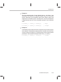
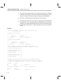
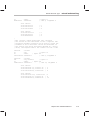
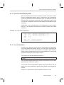
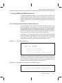
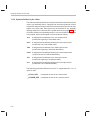
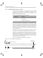
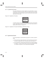
The initialized section directives (.text, .data, and .sect) tell the assembler to
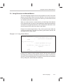
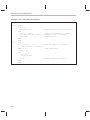
stop assembling into the current section and begin assembling into the indicated section. The .bss and .usect directives, however, do not end the current
section and begin a new one; they simply escape from the current section temporarily. The .bss and .usect directives can appear anywhere in an initialized
section without affecting its contents. For an example, see section 2.2.6, Using
Sections Directives, on page 2-8.
The assembler treats uninitialized subsections (created with the .usect directive) in the same manner as uninitialized sections. See section 2.2.4, Subsections, on page 2-7 for more information on creating subsections.
Introduction to Common Object File Format
2-5
How the Assembler Handles Sections
2.2.2
Initialized Sections
Initialized sections contain executable code or initialized data. The contents
of these sections are stored in the object file and placed in TMS320C6000
memory when the program is loaded. Each initialized section is independently
relocatable and may reference symbols that are defined in other sections. The
linker automatically resolves these section-relative references.
Three directives tell the assembler to place code or data into a section. The
syntaxes for these directives are:
.text
.data
.sect “section name”
When the assembler encounters one of these directives, it stops assembling
into the current section (acting as an implied end of current section command).
It then assembles subsequent code into the designated section until it encounters another .text, .data, or .sect directive.
Sections are built through an iterative process. For example, when the assembler first encounters a .data directive, the .data section is empty. The statements following this first .data directive are assembled into the .data section
(until the assembler encounters a .text or .sect directive). If the assembler
encounters subsequent .data directives, it adds the statements following
these .data directives to the statements already in the .data section. This
creates a single .data section that can be allocated continuously into memory.
Initialized subsections are created with the .sect directive. The assembler
treats initialized subsections in the same manner as initialized sections. See
section 2.2.4, on page 2-7 for more information on creating subsections.
2.2.3
Named Sections
Named sections are sections that you create. You can use them like the default
.text, .data, and .bss sections, but they are assembled separately.
For example, repeated use of the .text directive builds up a single .text section
in the object file. When linked, this .text section is allocated into memory as a
single unit. Suppose there is a portion of executable code (perhaps an initialization routine) that you do not want allocated with .text. If you assemble this
segment of code into a named section, it is assembled separately from .text,
and you can allocate it into memory separately. You can also assemble initialized data that is separate from the .data section, and you can reserve space
for uninitialized variables that is separate from the .bss section.
2-6
How the Assembler Handles Sections
Two directives let you create named sections:
- The .usect directive creates uninitialized sections that are used like the
.bss section. These sections reserve space in RAM for variables.
- The .sect directive creates initialized sections, like the default .text and
.data sections, that can contain code or data. The .sect directive creates
named sections with relocatable addresses.
The syntaxes for these directives are:
symbol .usect “section name”, size in bytes [, alignment [, bank offset ] ]
.sect “section name”
The section name parameter is the name of the section. Section names are
significant to 200 characters. You can create up to 32 767 separate named
sections. For the .usect and .sect directives, a section name can refer to a
subsection; see section 2.2.4 for details.
Each time you invoke one of these directives with a new name, you create a
new named section. Each time you invoke one of these directives with a name
that was already used, the assembler assembles code or data (or reserves
space) into the section with that name. You cannot use the same names with
different directives. That is, you cannot create a section with the .usect directive and then try to use the same section with .sect.
2.2.4
Subsections
Subsections are smaller sections within larger sections. Like sections, subsections can be manipulated by the linker. Subsections give you tighter control
of the memory map. You can create subsections by using the .sect or .usect
directive. The syntaxes for a subsection name are:
symbol .usect ”section name:subsection name ”, size in bytes
[, alignment [, bank offset ] ]
.sect ”section name :subsection name”
A subsection is identified by the base section name followed by a colon and
the name of the subsection. A subsection can be allocated separately or
grouped with other sections using the same base name. For example, you
create a subsection called _func within the .text section:
.sect ”.text:_func”
Using the linker’s SECTIONS directive, you can allocate .text:_func separately, or with all the .text sections. See section 7.8.1, SECTIONS Directive
Syntax, on page 7-28, for an example using subsections.
Introduction to Common Object File Format
2-7
How the Assembler Handles Sections
You can create two types of subsections:
- Initialized subsections are created using the .sect directive. See section
2.2.2, Initialized Sections, on page 2-6.
- Uninitialized subsections are created using the .usect directive. See sec-
tion 2.2.1, Uninitialized Sections, on page 2-4.
Subsections are allocated in the same manner as sections. See section 7.8,
The SECTIONS Directive, on page 7-28, for more information.
2.2.5
Section Program Counters
The assembler maintains a separate program counter for each section. These
program counters are known as section program counters, or SPCs.
An SPC represents the current address within a section of code or data.
Initially, the assembler sets each SPC to 0. As the assembler fills a section with
code or data, it increments the appropriate SPC. If you resume assembling into
a section, the assembler remembers the appropriate SPC’s previous value
and continues incrementing the SPC from that value.
The assembler treats each section as if it began at address 0; the linker relocates each section according to its final location in the memory map. For more
information, see section 2.4, Relocation, on page 2-14.
2.2.6
Using Sections Directives
Example 2–1 shows how you can build COFF sections incrementally, using
the sections directives to swap back and forth between the different sections.
You can use sections directives to begin assembling into a section for the first
time, or to continue assembling into a section that already contains code. In
the latter case, the assembler simply appends the new code to the code that
is already in the section.
The format in Example 2–1 is a listing file. Example 2–1 shows how the SPCs
are modified during assembly. A line in a listing file has four fields:
Field 1
contains the source code line counter.
Field 2
contains the section program counter.
Field 3
contains the object code.
Field 4
contains the original source statement.
See section 3.10, Source Listings, on page 3-30 for more information on interpreting the fields in a source listing.
2-8
How the Assembler Handles Sections
Example 2–1. Using Sections Directives
1
2
3
4 00000000
5 00000000 00000011
00000004 00000022
6
7
8
9 00000000
10 00000004
11
12
13
14 00000008 00001234
15
16
17
18 00000000
19 00000000 00800528
20 00000004 021085E0
21
22 00000008 01003664
23 0000000c 00004000
24 00000010 0087E1A0
25 00000014 021041E0
26 00000018 80000112
27 0000001c 00008000
28
29 00000020 0200007C–
30
31
32
33 0000000c
34 0000000c 000000AA
00000010 000000BB
00000014 000000CC
35
36
37
38 00000000
39 00000004
40
41
42
43 00000024
44 00000024 01003664
45 00000028 00006000
46 0000002c 020C4480
47 00000030 02800028–
48 00000034 02800068–
49 00000038 02140274
50
51
52
53 00000000
54 00000000 00000012’
55 00000004 00008000
Field 1 Field 2
Field 3
**************************************************
** Assemble an initialized table into .data.
**
**************************************************
.data
coeff
.word
011h,022h
**************************************************
** Reserve space in .bss for a variable.
**
**************************************************
.bss
var1,4
.bss
buffer,40
**************************************************
** Still in .data section
**
**************************************************
ptr
.word
01234h
**************************************************
** Assemble code into .text section
**
**************************************************
.text
sum:
MVK
10,A1
ZERO
A4
aloop:
[A1]
LDW
NOP
SUB
ADD
B
NOP
*A0++,A2
3
A1,1,A1
A2,A4,A4
aloop
5
STW
A4, *+B14(var1)
**************************************************
** Assemble another initialized table in .data **
**************************************************
.data
ivals
.word
0aah, 0bbh, 0cch
**************************************************
** Define another section for more variables. **
**************************************************
var2
.usect ”newvars”,4
inbuf
.usect ”newvars”,4
**************************************************
** Assemble more code into the .text section. **
**************************************************
.text
xmult: LDW
*A0++,A2
NOP
4
MPYHL
A2,A3,A4
MVKL
var2,A5
MVKH
var2,A5
STW
A4,*A5
***************************************************
** Define a named section for interrupt vectors **
***************************************************
.sect
”vectors”
B
sum
NOP
5
Field 4
Introduction to Common Object File Format
2-9
How the Assembler Handles Sections
As Figure 2–2 shows, the file in Example 2–1 creates five sections:
.text
.data
vectors
.bss
newvars
contains 15 32-bit words of object code.
contains six words of initialized data.
is a named section created with the .sect directive; it contains two
words of object code.
reserves 44 bytes in memory.
is a named section created with the .usect directive; it contains
eight bytes in memory.
The second column shows the object code that is assembled into these sections; the first column shows the source statements that generated the object
code.
Figure 2–2. Object Code Generated by the File in Example 2–1
Line numbers
Object code
Section
19
20
22
23
24
25
26
27
29
44
45
46
47
48
49
00800528
021085E0
01003664
00004000
0087E1A0
021041E0
80000112
00008000
0200007C–
01003664
00006000
020C4480
02800028–
02800068–
02140274
.text
5
5
14
34
34
34
00000011
00000022
00001234
000000AA
000000BB
000000CC
.data
54
54
00000000’
00000024’
vectors
No data—
44 bytes
reserved
.bss
9
10
38
39
2-10
No data—
8 bytes
reserved
newvars
How the Linker Handles Sections
2.3
How the Linker Handles Sections
The linker has two main functions related to sections. First, the linker uses the
sections in COFF object files as building blocks; it combines input sections
(when more than one file is being linked) to create output sections in an executable COFF output module. Second, the linker chooses memory addresses for
the output sections.
Two linker directives support these functions:
- The MEMORY directive allows you to define the memory map of a target
system. You can name portions of memory and specify their starting
addresses and their lengths.
- The SECTIONS directive tells the linker how to combine input sections
into output sections and where to place these output sections in memory.
Subsections allow you to manipulate sections with greater precision. You can
specify subsections with the linker’s SECTIONS directive. If you do not specify
a subsection explicitly, then the subsection is combined with the other sections
with the same base section name.
It is not always necessary to use linker directives. If you do not use them, the
linker uses the target processor’s default allocation algorithm described in section 7.12, Default Allocation Algorithm. When you do use linker directives, you
must specify them in a linker command file.
Refer to the following sections for more information about linker command files
and linker directives:
Section
Page
7.5
Linker Command Files . . . . . . . . . . . . . . . . . . . . . . . . . . . . . . . . . . . . . 7-20
7.7
The MEMORY Directive . . . . . . . . . . . . . . . . . . . . . . . . . . . . . . . . . . . 7-25
7.8
The SECTIONS Directive . . . . . . . . . . . . . . . . . . . . . . . . . . . . . . . . . . 7-28
7.12 Default Allocation Algorithm . . . . . . . . . . . . . . . . . . . . . . . . . . . . . . . . 7-51
Introduction to Common Object File Format
2-11
How the Linker Handles Sections
2.3.1
Default Memory Allocation
Figure 2–3 illustrates the process of linking two files together.
Figure 2–3. Combining Input Sections to Form an Executable Object Module
file1.obj
.text
.bss
Executable
object module
.data
file1
(.text)
Init
(named section)
file2
(.text)
file1
(.data)
file2
(.data)
file1
(.bss)
file2.obj
Memory map
Executable
code
(.text)
Initialized
data
(.data)
Space for
variables
(.bss)
.text
file2
(.bss)
.bss
Init
Init
.data
Tables
Tables
Tables
(named section)
In Figure 2–3, file1.obj and file2.obj have been assembled to be used as linker
input. Each contains the .text, .data, and .bss default sections; in addition,
each contains a named section. The executable object module shows the
combined sections. The linker combines the .text section from file1.obj and the
.text section from file2.obj to form one .text section, then combines the two
.data sections and the two .bss sections, and finally places the named sections
at the end. The memory map shows how the sections are put into memory; by
default, the linker begins at 0h and places the sections one after the other in
the following order: .text, .const, .data, .bss, .cinit, and then any named
sections in the order they are encountered in the input files.
The C/C++ compiler uses the .const section to store string constants, and variables or arrays that are defined as far const. The C/C++ compiler produces
tables of data for autoinitializing global variables; these variables are stored
in a named section called .cinit (see Figure 7–5 on page 7-69). For more
information on the .const and .cinit sections, see the TMS320C6000 Optimizing Compiler User’s Guide.
2-12
How the Linker Handles Sections
2.3.2
Placing Sections in the Memory Map
Figure 2–3 illustrates the linker’s default method for combining sections.
Sometimes you may not want to use the default setup. For example, you may
not want all of the .text sections to be combined into a single .text section. Or
you may want a named section placed where the .data section would normally
be allocated. Most memory maps contain various types of memory (RAM,
ROM, EPROM, etc.) in varying amounts; you may want to place a section in
a specific type of memory.
For further explanation of section placement within the memory map, see the
discussions in section 7.7, The MEMORY Directive, on page 7-25, and section 7.8, The SECTIONS Directive, on page 7-28.
Introduction to Common Object File Format
2-13
Relocation
2.4
Relocation
The assembler treats each section as if it began at address 0. All relocatable
symbols (labels) are relative to address 0 in their sections. Of course, all
sections cannot actually begin at address 0 in memory, so the linker relocates
sections by:
- Allocating them into the memory map so that they begin at the appropriate
address as defined with the linker’s MEMORY directive
- Adjusting symbol values to correspond to the new section addresses
- Adjusting references to relocated symbols to reflect the adjusted symbol
values
The linker uses relocation entries to adjust references to symbol values. The
assembler creates a relocation entry each time a relocatable symbol is referenced. The linker then uses these entries to patch the references after the
symbols are relocated. Example 2–2 contains a code segment for a
TMS320C6000 device that generates relocation entries.
Example 2–2. Code That Generates Relocation Entries
1
2
3
4
5
6
7
8
9
00000000
00000004
00000008
0000000c
00000012! Z:
0180082A’
0180006A’
00004000
00000010 0001E000
00000014 00000212
00000018 00008000
Y:
.global
B
MVKL
MVKH
NOP
X
X
Y,B3
Y,B3
3
IDLE
B
NOP
Y
5
; Uses an external relocation
; Uses an internal relocation
; Uses an internal relocation
In Example 2–2, both symbols X and Y are relocatable. Y is defined in the .text
section of this module; X is defined in another module. When the code is
assembled, X has a value of 0 (the assembler assumes all undefined external
symbols have values of 0), and Y has a value of 16 (relative to address 0 in
the .text section). The assembler generates two relocation entries: one for X
and one for Y. The reference to X is an external reference (indicated by the !
character in the listing). The reference to Y is to an internally defined
relocatable symbol (indicated by the ’ character in the listing).
2-14
Relocation
After the code is linked, suppose that X is relocated to address 0x7100. Suppose also that the .text section is relocated to begin at address 0x7200; Y now
has a relocated value of 0x7210. The linker uses the two relocation entries to
patch the two references in the object code:
00000012
0180082A
0180006A
B
MVKL
MVKH
X
Y
Y
becomes
becomes
becomes
0fffe012
01B9082A
1860006A
Sometimes an expression contains more than one relocatable symbol, or cannot be evaluated at assembly time. In this case, the assembler encodes the
entire expression in the object file. After determining the addresses of the symbols, the linker computes the value of the expression. For example:
Example 2–3. Simple Assembler Listing
1
2
3
00000000 00800028%
.global
sym1, sym2
MVKL
sym2 – sym1, A1
The symbols sym1 and sym2 are both externally defined. Therefore, the
assembler cannot evaluate the expression sym2 – sym1, so it encodes the
expression in the object file. The ’%’ listing character indicates a relocation
expression. Suppose the linker relocates sym2 to 300h and sym1 to 200h.
Then the linker computes the value of the expression to be 300h – 200h =
100h. Thus the MVK instruction is patched to:
00808028
MVK
100h,A1
Note: Expression Can Not Be Larger Than Space Reserved
If the value of an expression is larger, in bits, then the space reserved for it,
you will receive an error message from the linker.
Each section in a COFF object file has a table of relocation entries. The table
contains one relocation entry for each relocatable reference in the section. The
linker usually removes relocation entries after it uses them. This prevents the
output file from being relocated again (if it is relinked or when it is loaded). A
file that contains no relocation entries is an absolute file (all its addresses are
absolute addresses). If you want the linker to retain relocation entries, invoke
the linker with the –r option (see page 7-7).
Introduction to Common Object File Format
2-15
Run-Time Relocation
2.5
Run-Time Relocation
At times you may want to load code into one area of memory and run it in
another. For example, you may have performance-critical code in an externalmemory-based system. The code must be loaded into external memory, but
it would run faster in internal memory.
The linker provides a simple way to handle this. Using the SECTIONS directive, you can optionally direct the linker to allocate a section twice: first to set
its load address and again to set its run address. Use the load keyword for the
load address and the run keyword for the run address.
The load address determines where a loader places the raw data for the
section. Any references to the section (such as references to labels in it) refer
to its run address. The application must copy the section from its load address
to its run address before the first reference of the symbol is encountered at run
time; this does not happen automatically simply because you specify a separate run address. For an example that illustrates how to move a block of code
at run-time, see Example 7–6 on page 7-43.
If you provide only one allocation (either load or run) for a section, the section
is allocated only once and loads and runs at the same address. If you provide
both allocations, the section is actually allocated as if it were two separate sections of the same size.
Uninitialized sections (such as .bss) are not loaded, so the only significant
address is the run address. The linker allocates uninitialized sections only
once; if you specify both run and load addresses, the linker warns you and
ignores the load address.
For a complete description of run-time relocation, see section 7.9, Specifying
a section’s Run-Time Address, on page 7-40.
2-16
Loading a Program
2.6
Loading a Program
The linker produces executable COFF object modules. An executable object
file has the same COFF format as object files that are used as linker input; the
sections in an executable object file, however, are combined and relocated
into target memory.
To run a program, the data in the executable object module must be transferred, or loaded, into target system memory. Several methods can be used
for loading a program, depending on the execution environment. Three common situations are described below:
- Code Composer Studio can load an executable COFF file into a simulator
or onto hardware. The CCS loader reads the executable file and copies
the program into target memory.
- You can use the hex conversion utility (hex6x, which is shipped as part of
the assembly language package) to convert the executable COFF object
module into one of several object file formats. You can then use the converted file with an EPROM programmer to burn the program into an
EPROM.
- A standalone simulator can be invoked by the load6x command and the
name of the executable object file. The standalone simulator reads the
executable file, copies the program into the simulator and executes it,
displaying any C I/O.
Introduction to Common Object File Format
2-17
Symbols in a COFF File
2.7
Symbols in a COFF File
A COFF file contains a symbol table that stores information about symbols in
the program. The linker uses this table when it performs relocation. Debugging
tools can also use the symbol table to provide symbolic debugging.
2.7.1
External Symbols
External symbols are symbols that are defined in one module and referenced
in another module. You can use the .def, .ref, or .global directive to identify
symbols as external:
.def
The symbol is defined in the current module and used in
another module.
.ref
The symbol is referenced in the current module, but defined
in another module.
.global
The symbol may be either of the above.
The following code segment illustrates these definitions.
q:
x:
.def
.ref
.global
.global
x
y
z
q
B
NOP
MVK
MV
MVKL
MVKH
B
NOP
B3
4
1, 1
A0,A1
y,B3
y,B3
z
5
In this example, the .def definition of x says that it is an external symbol defined
in this module and that other modules can reference x. The .ref definition of
y says that it is an undefined symbol that is defined in another module. The
.global definition of z says that it is defined in some module and available in
this file. The .global definition of q says that it is defined in this module and that
other modules can reference q.
The assembler places x, y, z, and q in the object file’s symbol table. When the
file is linked with other object files, the entries for x and q resolve references
to x and q in other files. The entries for y and z cause the linker to look through
the symbol tables of other files for y’s and z’s definitions.
The linker must match all references with corresponding definitions. If the
linker cannot find a symbol’s definition, it prints an error message about the
unresolved reference. This type of error prevents the linker from creating an
executable object module.
2-18
Symbols in a COFF File
2.7.2
The Symbol Table
The assembler always generates an entry in the symbol table when it encounters an external symbol (both definitions and references defined by one of the
directives in section 2.7.1). The assembler also creates special symbols that
point to the beginning of each section; the linker uses these symbols to relocate references to other symbols.
The assembler does not usually create symbol table entries for any symbols
other than those described above, because the linker does not use them. For
example, labels are not included in the symbol table unless they are declared
with the .global directive. For symbolic debugging purposes, it is sometimes
useful to have entries in the symbol table for each symbol in a program. To
accomplish this, invoke the assembler with the –as option (see page 3-6).
Introduction to Common Object File Format
2-19
Chapter 3
Assembler Description
The TMS320C6000 assembler translates assembly language source files
into machine language object files. These files are in common object file format
(COFF), which is discussed in Chapter 2, Introduction to Common Object File
Format, and Appendix A, Common Object File Format. Source files can contain the following assembly language elements:
Assembler directives
described in Chapter 4
Macro directives
described in Chapter 5
Assembly language instructions
described in the TMS320C6000 CPU
and Instruction Set Reference Guide
Topic
Page
3.1
Assembler Overview . . . . . . . . . . . . . . . . . . . . . . . . . . . . . . . . . . . . . . . . . . 3-2
3.2
The Assembler’s Role in the Software Development Flow . . . . . . . . 3-3
3.3
Invoking the Assembler . . . . . . . . . . . . . . . . . . . . . . . . . . . . . . . . . . . . . . . 3-4
3.4
Naming Alternate Directories for Assembler Input . . . . . . . . . . . . . . . 3-7
3.5
Source Statement Format . . . . . . . . . . . . . . . . . . . . . . . . . . . . . . . . . . . . . . 3-9
3.6
Constants . . . . . . . . . . . . . . . . . . . . . . . . . . . . . . . . . . . . . . . . . . . . . . . . . . . 3-13
3.7
Character Strings . . . . . . . . . . . . . . . . . . . . . . . . . . . . . . . . . . . . . . . . . . . . 3-16
3.8
Symbols . . . . . . . . . . . . . . . . . . . . . . . . . . . . . . . . . . . . . . . . . . . . . . . . . . . . 3-17
3.9
Expressions . . . . . . . . . . . . . . . . . . . . . . . . . . . . . . . . . . . . . . . . . . . . . . . . . 3-25
3.10 Source Listings . . . . . . . . . . . . . . . . . . . . . . . . . . . . . . . . . . . . . . . . . . . . . . 3-30
3.11 Cross-Reference Listings . . . . . . . . . . . . . . . . . . . . . . . . . . . . . . . . . . . . . 3-33
Assembler Description
3-1
Assembler Overview
3.1 Assembler Overview
The 2-pass assembler does the following:
- Processes the source statements in a text file to produce a relocatable
object file
- Produces a source listing (if requested) and provides you with control over
this listing
- Allows you to segment your code into sections and maintain a section pro-
gram counter (SPC) for each section of object code
- Defines and references global symbols and appends a cross-reference
listing to the source listing (if requested)
- Allows conditional assembly
- Supports macros, allowing you to define macros inline or in a library
3-2
The Assembler’s Role in the Software Development Flow
3.2
The Assembler’s Role in the Software Development Flow
Figure 3–1 illustrates the assembler’s role in the software development flow.
The shaded portion highlights the most common assembler development
path. The assembler accepts assembly language source files as input, both
those you create and those created by the TMS320C6000 C/C++ compiler.
Figure 3–1. The Assembler in the TMS320C6000 Software Development Flow
C/C++
source
files
Macro
source
files
Archiver
C/C++
compiler
Assembly
optimizer
source
Assembler
source
Assembly
optimizer
Macro
library
Assembler
Archiver
Library of
object
files
Linker
Executable
COFF
file
Hex conversion
utility
EPROM
programmer
COFF
object
files
Cross-reference
lister
Assemblyoptimized
file
Library-build
utility
Run-timesupport
library
Debugging
tools
TMS320C6000
Assembler Description
3-3
Invoking the Assembler
3.3
Invoking the Assembler
To invoke the assembler, enter the following:
cl6x [options] [assembly source filenames]
cl6x
is the command that invokes the assembler.
assembly
source
filenames
names the assembly language source file. The file name must
contain a .asm extension.
object file
names the C6000 object file that the assembler creates. If you
do not supply an extension, the assembler uses .obj as a default.
If you do not supply an object file, the assembler creates a file
that uses the input filename with the .obj extension.
listing file
names the optional listing file that the assembler can create.
- If you do not supply a listing file, the assembler does not
create one unless you use the –l (lowercase L) option or the
–x option. In this case, the assembler uses the input filename
with a .lst extension and places the listing file in the input file
directory.
- If you supply a listing file but do not supply an extension, the
assembler uses .lst as the default extension.
options
3-4
identify the assembler options that you want to use. Options are
not case sensitive and can appear anywhere on the command
line following the command. Precede each option with a hyphen.
–@
–@ filename appends the contents of a file to the
command line. You can use this option to avoid limitations on command line length imposed by the
host operating system. Use an asterisk or a semicolon (* or ;) at the beginning of a line in the command file to include comments. Comments that
begin in any other column must begin with a semicolon.
–aa
creates an absolute listing. When you use –aa, the
assembler does not produce an object file. The
–aa option is used in conjunction with the absolute
lister.
–apd
same as -ppd and -ppi for compiler EXCEPT for
assembly fiels only and produce files with a .ppa
extension.
Invoking the Assembler
–api
same as -ppd and -ppi for compiler EXCEPT for
assembly fiels only and produce files with a .ppa
extension.
–ac
makes case insignificant in the assembly
language files. For example, –ac will make the
symbols ABC and abc equivalent. If you do not use
this option, case is significant (default). Case significance is enforced primarily with symbol names,
not with mnemonics and register names.
–ad
–adname [=value] sets the name symbol. This is
equivalent to inserting name .set [value] at the
beginning of the assembly file. If value is omitted,
the symbol is set to 1. For more information, see
section 3.8.4, Defining Symbolic Constants (–d
Option), on page 3-20.
–af
suppresses the assembler’s default behavior of
adding the .asm extension to an input file with no
specified extension.
–g
enables assembler source debugging in the C
source debugger. Line information is output to the
COFF file for every line of source in the assembly
language source file. You cannot use the –g option
on assembly code that contains .line directives.
–ahc
–ahcfilename tells the assembler to copy the specified file for the assembly module. The file is inserted before source file statements. The copied
file appears in the assembly listing files.
–ahi
–ahifilename tells the assembler to include the
specified file for the assembly module. The file is
included before source file statements. The included file does not appear in the assembly listing
files.
–i
specifies a directory where the assembler can find
files named by the .copy, .include, or .mlib directives. The format of the –i option is –ipathname.
You can specify up to 32 directories in this manner;
each pathname must be preceded by the –i option.
For more information, see section 3.4.1, Using the
– i Assembler Option, on page 3-7.
–al
(lowercase L) produces a listing file with the same
name as the input file with a .lst extension.
Assembler Description
3-5
Invoking the Assembler
–me
produces object code in big-endian format.
–ml
–mlnum
sets
the
processor
symbols
.SMALL_MODEL,
.LARGE_MODEL,
and
.LARGE_MODEL_OPTION. If you are compiling
C/C++ code separately, you can use this option to
mimic the compiler’s –mlnum option. If you are
compiling with C/C++ code, the –mlnum information is passed to the assembler, and the model
symbols are appropriately defined.
–mm
suppresses MVK warnings. By default, the assembler issues warnings when an MVK constant expression that is part of a well-defined expression
does not fit within 16-bits signed (–32768 to
32767). If the constant operand is a symbol or expression that cannot be evaluated by the assembler, the warning is issued by the linker when the
corresponding object file is linked. The –mm option
suppresses the assembler and linker behavior.
Alternately, use the MVKL instruction. It has the
same properties as MVK, except one: the constant
expression is not limited to 16-bits. MVKL sign-extends the constant when loading it into the register.
Use MVKL only with MVKH, otherwise, use MVK.
–mv<silicon>
3-6
Specifiy target silicon version
–q
suppresses the banner and progress information
(assembler runs in quiet mode).
–as
puts all defined symbols in the object file’s symbol
table. The assembler usually puts only global symbols into the symbol table. When you use –as,
symbols defined as labels or as assembly-time
constants are also placed in the table.
–au
–auname undefines the predefined constant
name, which overrides any –ad options for the
specified constant.
–ax
produces a cross-reference table and appends it
to the end of the listing file; it also adds cross-reference information to the object file for use by the
cross-reference utility. If you do not request a listing file but use the –ax option, the assembler creates a listing file automatically, naming it with the
same name as the input file with a .lst extension.
Naming Alternate Directories for Assembler Input
3.4
Naming Alternate Directories for Assembler Input
The .copy, .include, and .mlib directives tell the assembler to use code from
external files. The .copy and .include directives tell the assembler to read
source statements from another file, and the .mlib directive names a library
that contains macro functions. Chapter 4, Assembler Directives, contains
examples of the .copy, .include, and .mlib directives. The syntax for these
directives is:
.copy [”]filename[”]
.include [”]filename[”]
.mlib [”]filename[”]
The filename names a copy/include file that the assembler reads statements
from or a macro library that contains macro definitions. The filename may be
a complete pathname, a partial pathname, or a filename with no path information. The assembler searches for the file in the following locations in the order
given:
1) The directory that contains the current source file. The current source file
is the file being assembled when the .copy, .include, or .mlib directive is
encountered.
2) Any directories named with the –i assembler option
3) Any directories named with the C6X_A_DIR or A_DIR environment variable
Because of this search hierarchy, you can augment the assembler’s directory
search algorithm by using the – i assembler option (described in section 3.4.1)
or the C6X_A_DIR or A_DIR environment variable (described in section
3.4.2).
3.4.1
Using the –i Assembler Option
The –i assembler option names an alternate directory that contains copy/
include files or macro libraries. The format of the –i option is as follows:
cl6x –ipathname source filename [other options]
You can use up to 32 –i options per invocation; each –i option names one
pathname. In assembly source, you can use the .copy, .include, or .mlib directive without specifying path information. If the assembler does not find the file
in the directory that contains the current source file, it searches the paths
designated by the –i options.
Assembler Description
3-7
Naming Alternate Directories for Assembler Input
For example, assume that a file called source.asm is in the current directory;
source.asm contains the following directive statement:
.copy ”copy.asm”
Assume the following paths for the copy.asm file:
UNIX:
/320tools/files/copy.asm
Windows:
c:\320tools\files\copy.asm
Operating System
Enter
UNIX
cl6x –i/320tools/files source.asm
Windows
cl6x –ic:\320tools\files source.asm
If you invoke the assembler for your system as as shown above, the assembler
first searches for copy.asm in the current directory because source.asm (the
input file) is in the current directory. Then the assembler searches in the
directory named with the – i option.
3.4.2
Using the C6X_A_DIR or A_DIR Environment Variable
An environment variable is a system symbol that you define and assign a string
to. The assembler uses the A_DIR environment variable to name alternate
directories that contain copy/include files or macro libraries. The command
syntax for assigning the environment variable is as follows:
Operating System
Enter
UNIX
setenv A_DIR ”pathname1 ;pathname2 ; . . .”
Windows
set A_DIR= pathname1 ;pathname2 ; . . .
The pathnames are directories that contain copy/include files or macro libraries. You can separate the pathnames with a semicolon or with blanks. In
assembly source, you can use the .copy, .include, or .mlib directive without
specifying path information. If the assembler does not find the file in the directory that contains the current source file or in directories named by the –i
option, it searches the paths named by the environment variable.
For setup information for the C6X_A_DIR or A_DIR environment variable, refer to the DosRun.bat file provide with Code Composer Studio. If A_DIR is not
set up, the assembler uses C_DIR to specify the include file search path. See
the TMS320C6000 Optimizing Compiler User’s Guide for details on C_DIR.
3-8
Source Statement Format
3.5
Source Statement Format
TMS320C6000 assembly language source programs consist of source statements that can contain assembler directives, assembly language instructions,
macro directives, and comments. A source statement can contain five ordered
fields (label, mnemonic, unit specifier, operand list, and comment). The general syntax for source statements is as follows:
[label[:] ] [||] [ [register] ] mnemonic [unit specifier] [operand list ] [;comment ]
Following are examples of source statements:
two
.set 2
; Symbol Two = 2
Label: MVK
two,A2 ; Move 2 into register A2
.word 016h
; Initialize a word with 016h
The C6000 assembler reads up to 200 characters per line. Any characters
beyond 200 are truncated. Keep the operational part of your source statements (that is, everything other than comments) less than 200 characters in
length for correct assembly. Your comments can extend beyond the 200-character limit, but the truncated portion is not included in the listing file.
Follow these guidelines:
- All statements must begin with a label, a blank, an asterisk, or a semicolon.
- Labels are optional; if used, they must begin in column 1.
- One or more blanks must separate each field. Tab and space characters
are blanks. You must separate the operand list from the preceding field
with a blank.
- Comments are optional. Comments that begin in column 1 can begin with
an asterisk or a semicolon (* or ;), but comments that begin in any other
column must begin with a semicolon.
- In a conditional instruction, the condition register must be surrounded by
square brackets.
- The functional unit specifier is optional. If you do not specify the functional
unit, the assembler assigns a legal functional unit based on the mnemonic
field.
- A mnemonic cannot begin in column 1 or it will be interpreted as a label.
The following sections describe each of the fields.
Assembler Description
3-9
Source Statement Format
3.5.1
Label Field
Labels are optional for all assembly language instructions and for most (but
not all) assembler directives. When used, a label must begin in column 1 of a
source statement. A label can contain up to 128 alphanumeric characters
(A–Z, a–z, 0–9, _, and $). Labels are case sensitive (except when the –ac option is used), and the first character cannot be a number. A label can be followed by a colon (:). The colon is not treated as part of the label name. If you
do not use a label, the first character position must contain a blank, a semicolon, or an asterisk. You cannot use a label with an instruction that is in parallel
with a previous instruction.
When you use a label, its value is the current value of the SPC. The label points
to the statement it is associated with. For example, if you use the .word directive to initialize several words, a label points to the first word. In the following
example, the label Start has the value 40h.
.
.
.
.
.
.
.
.
.
.
.
.
9
10 00000040 0000000A
00000044 00000003
00000048 00000007
* Assume some code was assembled
Start: .word 0Ah,3,7
A label on a line by itself is a valid statement. The label assigns the current
value of the section program counter to the label; this is equivalent to the following directive statement:
label .equ
$
; $ provides the current value of the SPC
When a label appears on a line by itself, it points to the instruction on the next
line (the SPC is not incremented):
1 00000000
2 00000000 00000003
Here:
.word 3
If you do not use a label, the character in column 1 must be a blank, an asterisk,
or a semicolon.
3-10
Source Statement Format
3.5.2
Mnemonic Field
The mnemonic field follows the label field. The mnemonic field cannot start in
column 1; if it does, it is interpreted as a label. There is one exception – the
parallel bars (||) of the mnemonic field can start in column 1. The mnemonic
field can begin with one of the following items:
- Pipe symbols (||) indicate instructions that are in parallel with a previous
instruction. You can have up to eight instructions running in parallel. The
following example demonstrates six instructions running in parallel:
Inst1
Inst2
Inst3
Inst4
Inst5
Inst6
Inst7
||
||
||
||
||
These five instructions run in
parallel with the first instruction.
- Square brackets ( [ ] ) indicate conditional instructions. The machine-
instruction mnemonic is executed based on the value of the register within
the brackets; valid register names are A0 for ’C64xx only, A1, A2, B0, B1,
and B2. The instruction is executed if the value of the register is nonzero.
If the register name is preceded by an exclamation point (!), then the
instruction is executed if the value of the register is 0. For example:
[A1] ZERO A2
; If A1 is not equal to zero, A2 = 0
Next, the mnemonic field contains one of the following items:
-
3.5.3
Machine-instruction mnemonic (such as ADDK, MVKH, B)
Assembler directive (such as .data, .list, .equ)
Macro directive (such as .macro, .var, .mexit)
Macro call
Unit Specifier Field
The unit specifier field is an optional field that follows the mnemonic field for
machine-instruction mnemonics. The unit specifier field begins with a period
(.) followed by a functional unit specifier. In general, one instruction can be
assigned to each functional unit in a single instruction cycle. There are eight
functional units, two of each functional type:
.D1 and .D2
Data/addition/subtraction
.L1 and .L2
ALU/compares/long data arithmetic
.M1 and .M2
Multiply
.S1 and .S2
Shift/ALU/branch/bit field
ALU refers to an arithmetic logic unit.
Assembler Description
3-11
Source Statement Format
There are several ways to use the unit specifier field:
- You can specify the particular functional unit (for example, .D1).
- You can specify only the functional type (for example, .M), and the assem-
bler assigns the specific unit (for example, .M2).
- If you do not specify the functional unit, the assembler assigns the func-
tional unit based on the mnemonic field and operand field.
For more information on functional units, including which assembly instructions require which functional type, see the TMS320C62x, C64x, C67x CPU
and Instruction Set Reference Guide.
3.5.4
Operand Field
The operand field follows the mnemonic field and contains one or more operands. The operand field is not required for all instructions or directives. An
operand consists of the following items:
- Symbols (see section 3.8 on page 3-17)
- Constants (see section 3.6 on page 3-13)
- Expressions (combination of constants and symbols; see section 3.9 on
page 3-25)
You must separate operands with commas.
3.5.5
Comment Field
A comment can begin in any column and extends to the end of the source line.
A comment can contain any ASCII character, including blanks. Comments are
printed in the assembly source listing, but they do not affect the assembly.
A source statement that contains only a comment is valid. If it begins in column 1, it can start with a semicolon ( ; ) or an asterisk ( *). Comments that begin
anywhere else on the line must begin with a semicolon. The asterisk identifies
a comment only if it appears in column 1.
3-12
Constants
3.6
Constants
The assembler supports six types of constants:
-
Binary integer
Octal integer
Decimal integer
Hexadecimal integer
Character
Assembly-time
The assembler maintains each constant internally as a 32-bit quantity.
Constants are not sign extended. For example, the constant 00FFh is equal
to 00FF (base 16) or 255 (base 10); it does not equal –1. However, when used
with the .byte directive, –1 is equivalent to 00FFh.
3.6.1
Binary Integers
A binary integer constant is a string of up to 32 binary digits (0s and 1s)
followed by the suffix B (or b). If fewer than 32 digits are specified, the assembler right justifies the value and fills the unspecified bits with zeros. These are
examples of valid binary constants:
3.6.2
00000000B
Constant equal to 010 or 016
0100000b
Constant equal to 3210 or 2016
01b
Constant equal to 110 or 116
11111000B
Constant equal to 24810 or 0F816
Octal Integers
An octal integer constant is a string of up to 11 octal digits (0 through 7) followed
by the suffix Q (or q). These are examples of valid octal constants:
10Q
Constant equal to 810 or 816
010
Constant equal to 810 or 816 (C format)
100000Q
Constant equal to 32 76810 or 800016
226q
Constant equal to 15010 or 9616
Assembler Description
3-13
Constants
3.6.3
Decimal Integers
A decimal integer constant is a string of decimal digits ranging from
–2 147 483 648 to 4 294 967 295. These are examples of valid decimal constants:
3.6.4
1000
Constant equal to 100010 or 3E816
–32768
Constant equal to –32 76810 or 800016
25
Constant equal to 2510 or 1916
Hexadecimal Integers
A hexadecimal integer constant is a string of up to eight hexadecimal digits followed by the suffix H (or h). Hexadecimal digits include the decimal values 0–9
and the letters A–F or a–f. A hexadecimal constant must begin with a decimal
value (0–9). If fewer than eight hexadecimal digits are specified, the assembler
right justifies the bits. These are examples of valid hexadecimal constants:
3.6.5
78h
Constant equal to 12010 or 007816
0x78
Constant equal to 12010 or 007816 (C format)
0Fh
Constant equal to 1510 or 000F16
37ACh
Constant equal to 14 25210 or 37AC16
Character Constants
A character constant is a single character enclosed in single quotes. The characters are represented internally as 8-bit ASCII characters. Two consecutive
single quotes are required to represent each single quote that is part of a character constant. A character constant consisting only of two single quotes is
valid and is assigned the value 0. These are examples of valid character
constants:
’a’
Defines the character constant a and is represented internally as 6116
’C’
Defines the character constant C and is represented internally as 4316
’’’’
Defines the character constant ’ and is represented internally as 2716
’’
Defines a null character and is represented internally as 0016
Notice the difference between character constants and character strings.
(section 3.7 discusses character strings). A character constant represents a
single integer value; a string is a sequence of characters.
3-14
Constants
3.6.6
Assembly-Time Constants
If you use the .set directive (see page 4-63) to assign a value to a symbol, the
symbol becomes a constant. To use this constant in expressions, the value
that is assigned to it must be absolute. For example:
sym
.set 3
MVK sym,B1
You can also use the .set directive to assign symbolic constants for register
names. In this case, the symbol becomes a synonym for the register:
sym
.set B1
MVK 10,sym
Assembler Description
3-15
Character Strings
3.7
Character Strings
A character string is a string of characters enclosed in double quotes. Double
quotes that are part of character strings are represented by two consecutive
double quotes. The maximum length of a string varies and is defined for each
directive that requires a character string. Characters are represented internally as 8-bit ASCII characters.
These are examples of valid character strings:
”sample program”
defines the 14-character string sample program.
”PLAN ””C”””
defines the 8-character string PLAN ”C”.
Character strings are used for the following:
-
3-16
Filenames, as in .copy ”filename”
Section names, as in .sect ”section name”
Data initialization directives, as in .byte ”charstring”
Operands of .string directives
Symbols
3.8
Symbols
Symbols are used as labels, constants, and substitution symbols. A symbol
name is a string of up to 200 alphanumeric characters (A–Z, a–z, 0–9, $,
and _ ). The first character in a symbol cannot be a number, and symbols cannot contain embedded blanks. The symbols you define are case sensitive; for
example, the assembler recognizes ABC, Abc, and abc as three unique symbols. You can override case sensitivity with the –ac assembler option (see
page 3-5). A symbol is valid only during the assembly in which it is defined,
unless you use the .global directive or the .def directive to declare it as an external symbol (see section 2.7.1 on page 2-18).
3.8.1
Labels
Symbols used as labels become symbolic addresses that are associated with
locations in the program. Labels used locally within a file must be unique. Mnemonic opcodes and assembler directive names without the . prefix are valid
label names.
Labels can also be used as the operands of .global, .ref, .def, or .bss directives;
for example:
.global label1
label2: MVKL
MVKH
B
NOP
3.8.2
label2, B3
label2, B3
label1
5
Local Labels
Local labels are special labels whose scope and effect are temporary. A local
label can be defined in two ways:
- $n, where n is a decimal digit in the range 0–9. For example, $4 and $1
are valid local labels. See Example 3–1.
- name?, where name is any legal symbol name as described above. The
assembler replaces the question mark with a period followed by a unique
number. When the source code is expanded, you will not see the unique
number in the listing file. Your label appears with the question mark as it
did in the source definition. You cannot declare this label as global. See
Example 3–2.
Normal labels must be unique (they can be declared only once), and they can
be used as constants in the operand field. Local labels, however, can be
undefined and defined again. Local labels cannot be defined by directives.
Assembler Description
3-17
Symbols
A local label can be undefined or reset in one of these ways:
-
By using the .newblock directive
By changing sections (using a .sect, .text, or .data directive)
By entering an include file (specified by the .include or .copy directive)
By leaving an include file (specified by the .include or .copy directive)
Example 3–1. Local Labels of the Form $n
This is an example of code that declares and uses a local label legally:
$1:
SUB
[A1] B
SUBC
NOP
A1,1,A1
$1
A3,A0,A3
4
.newblock
$1
SUB
[A2] B
MPY
NOP
; undefine $1 to use it again
A2,1,A2
$1
A3,A3,A3
4
The following code uses a local label illegally:
$1:
SUB
[A1] B
SUBC
NOP
$1
SUB
[A2] B
MPY
NOP
A1,1,A1
$1
A3,A0,A3
4
A2,1,A2
$1
A3,A3,A3
4
; WRONG — $1 is multiply defined
The $1 label is not undefined before being reused by the second branch
instruction. Therefore, $1 is redefined, which is illegal.
Local labels are especially useful in macros. If a macro contains a normal label
and is called more than once, the assembler issues a multiple-definition error.
If you use a local label and .newblock within a macro, however, the local label
is used and reset each time the macro is expanded.
Up to ten local labels can be in effect at one time. After you undefine a local
label, you can define it and use it again. Local labels do not appear in the object
code symbol table.
Because local labels are intended to be used only locally, branches to local
labels are not expanded in case the branch’s offset is out of range.
3-18
Symbols
Example 3–2. Local Labels of the Form name?
****************************************************************
** First definition of local label mylab
**
****************************************************************
nop
mylab? nop
B mylab?
nop 5
****************************************************************
** Include file has second definition of mylab
**
****************************************************************
.copy ”a.inc”
****************************************************************
** Third definition of mylab, reset upon exit from .include
**
****************************************************************
mylab? nop
B mylab?
nop 5
****************************************************************
** Fourth definition of mylab in macro, macros use different **
** namespace to avoid conflicts
**
****************************************************************
mymac .macro
mylab? nop
B mylab?
nop 5
.endm
****************************************************************
** Macro invocation
**
****************************************************************
mymac
****************************************************************
** Reference to third definition of mylab. Definition is not **
** reset by macro invocation.
**
****************************************************************
B mylab?
nop 5
****************************************************************
** Changing section, allowing fifth definition of mylab
**
****************************************************************
.sect ”Sect_One”
nop
mylab? .word 0
nop
nop
B mylab?
nop 5
****************************************************************
** The .newblock directive allows sixth definition of mylab
**
****************************************************************
.newblock
mylab? .word 0
nop
nop
B mylab?
nop 5
Assembler Description
3-19
Symbols
3.8.3
Symbolic Constants
Symbols can be set to constant values. By using constants, you can equate
meaningful names with constant values. The .set and .struct/.tag/.endstruct directives enable you to set constants to symbolic names. Symbolic constants
cannot be redefined. The following example shows how these directives can
be used:
K
.set
maxbuf .set
1024
2*K
; constant definitions
item
value
delta
i_len
.struct
.int
.int
.endstruct
;
;
;
;
item structure
value offset =
delta offset =
item size
=
definition
0
4
8
array
.tag item
.bss array, i_len*K ; declare an array of K ”items”
.text
LDW
*+B14(array.delta + 2*i_len),A1
; access array [2].delta
The assembler also has several predefined symbolic constants; these are
discussed in section 3.8.5.
3.8.4
Defining Symbolic Constants (–ad Option)
The –ad option equates a constant value with a symbol. The symbol can then
be used in place of a value in assembly source. The format of the –ad option
is as follows:
cl6x –adname=[value]
The name is the name of the symbol you want to define. The value is the value
you want to assign to the symbol. If the value is omitted, the symbol is set to 1.
Once you have defined the name with the –ad option, the symbol can be used
in place of a constant value, a well-defined expression, or an otherwise undefined symbol used with assembly directives and instructions. For example, on
the command line you enter:
cl6x –adSYM1=1 –adSYM2=2 –adSYM3=3 –adSYM4=4 value.asm
Since you have assigned values to SYM1, SYM2, SYM3, and SYM4, you can
use them in source code. Example 3–3 shows how the value.asm file uses
these symbols without defining them explicitly.
3-20
Symbols
Example 3–3. Using Symbolic Constants Defined on Command Line
If_4:
IF_5:
IF_6:
IF_7:
.if
.byte
.else
.byte
.endif
SYM4 = SYM2 * SYM2
SYM4
; Equal values
SYM2 * SYM2
; Unequal values
.if
.byte
.else
.byte
.endif
SYM1 <= 10
10
; Less than / equal
SYM1
; Greater than
.if
.byte
.else
.byte
.endif
SYM3 * SYM2 != SYM4 + SYM2
SYM3 * SYM2 ; Unequal value
.if
.elseif
.byte
.endif
SYM1 = SYM2
SYM2 + SYM3 = 5
SYM2 + SYM3
SYM4 + SYM4
; Equal values
.byte
SYM1
Within assembler source, you can test the symbol defined with the –ad option
with the following directives:
Type of Test
Directive Usage
Existence
.if $isdefed(”name”)
Nonexistence
.if $isdefed(”name”) = 0
Equal to value
.if name = value
Not equal to value
.if name != value
The argument to the $isdefed built-in function must be enclosed in quotes. The
quotes cause the argument to be interpreted literally rather than as a substitution symbol.
Assembler Description
3-21
Symbols
3.8.5
Predefined Symbolic Constants
The assembler has several predefined symbols, including the following types:
- $, the dollar-sign character, represents the current value of the section
program counter (SPC). $ is a relocatable symbol.
- Register symbols, including A0–A15 and B0–B15 for ’C6200 and
’C6700; and A16–31 and B16–31 for ’C6400.
- CPU control registers, including the following:
Register
Description
AMR
Addressing mode register
CSR
Control status register
FADCR (’C6700 only)
Floating-point adder configuration register
FAUCR (’C6700 only)
Floating-point auxiliary configuration register
FMCR (’C6700 only)
Floating-point multiplier configuration register
GFPGFR (’C6400 only)
Galois field polynomial generator function
register
ICR
Interrupt clear register
IER
Interrupt enable register
IFR
Interrupt flag register
NRP
Nonmaskable interrupt return pointer
IRP
Interrupt return pointer
ISR
Interrupt set register
ISTP
Interrupt service table pointer
PCE1
Program counter
Control registers can be entered as all upper-case or all lower-case characters; for example, CSR can also be entered as csr.
3-22
Symbols
- Processor symbols, including the following items:
Symbol name
Description
.TMS320C6000
Always set to 1
.TMS320C6200
Set to 1 for ’6200, otherwise 0
.TMS320C6400
Set to 1 for ’6400, otherwise 0
.TMS320C6700
Set to 1 for ’6700, otherwise 0
.LITTLE_ENDIAN Set to 1 if little-endian mode is selected (the –me assembler
option is not used); otherwise 0.
.BIG_ENDIAN
Set to 1 if big-endian mode is selected (the –me assembler
option is used); otherwise 0.
- Memory Model Symbols
Symbol name
Description
.SMALL_MODEL
Set to 1 if a small memory model is used (does
not use the –ml<num> option). Otherwise 0
.LARGE_MODEL
Set to 1 if a large memory model is used (does not
use the –ml<num> option). Otherwise 0
.LARGE_MODEL_OPTION
Always defined. Set to the value used with the
–ml option. The –ml option can be used when
invoking the shell (the C/C++ compiler) or the
assembler. See the TMS320C600 Optimizing
Compiler User’s Guide for more information on
the –ml option.
- Assembler Version Symbols
3.8.6
Symbol name
Description
.ASSEMBLER_VERSION
Always defined. Set to a number that consists of
a major version number and a 2-digit minor version number. The number does not contain a
decimal. For example, for version 5.00 of the assembler, .ASSEMBLER_VERSION is set to 500.
Substitution Symbols
Symbols can be assigned a string value (variable). This enables you to alias
character strings by equating them to symbolic names. Symbols that represent character strings are called substitution symbols. When the assembler
Assembler Description
3-23
Symbols
encounters a substitution symbol, its string value is substituted for the symbol
name. Unlike symbolic constants, substitution symbols can be redefined.
A string can be assigned to a substitution symbol anywhere within a program;
for example:
.global
.asg
.asg
.asg
_table
”B14”, PAGEPTR
”*+B15(4)”, LOCAL1
”*+B15(8)”, LOCAL2
LDW
NOP
STW
*+PAGEPTR(_table),A0
4
A0,LOCAL1
When you are using macros, substitution symbols are important because
macro parameters are actually substitution symbols that are assigned a macro
argument. The following code shows how substitution symbols are used in
macros:
MAC .macro
MPY
NOP
ADD
.endm
src1, src2, dst ; Multiply/Accumulate macro
src1, src2, src2
src2, dst, dst
* MAC macro invocation
MAC A0,A1,A2
For more information about macros, see Chapter 5, Macro Language.
3-24
Expressions
3.9
Expressions
An expression is a constant, a symbol, or a series of constants and symbols
separated by arithmetic operators. The 32-bit ranges of valid expression values are –2 147 483 648 to 2 147 483 647 for signed values, and 0 to
4 294 967 295 for unsigned values. Three main factors influence the order of
expression evaluation:
Parentheses
Expressions enclosed in parentheses are always
evaluated first.
8 / (4 / 2) = 4, but 8 / 4 / 2 = 1
You cannot substitute braces ( { } ) or brackets ( [ ] )
for parentheses.
Precedence groups
Operators, listed in Table 3–1, are divided into nine
precedence groups. When parentheses do not
determine the order of expression evaluation, the
highest precedence operation is evaluated first.
8 + 4 / 2 = 10 (4 / 2 is evaluated first)
Left-to-right evaluation When parentheses and precedence groups do not
determine the order of expression evaluation, the
expressions are evaluated from left to right, except
for Group 1, which is evaluated from right to left.
8 / 4*2 = 4, but 8 / (4*2) = 1
Assembler Description
3-25
Expressions
3.9.1
Operators
Table 3–1 lists the operators that can be used in expressions, according to
precedence group.
Table 3–1. Operators Used in Expressions (Precedence)
Note:
3.9.2
Group
Operator
Description
1
+
–
~
!
Unary plus
Unary minus
1s complement
Logical NOT
2
*
/
%
Multiplication
Division
Modulo
3
+
–
Addition
Subtraction
4
<<
>>
Shift left
Shift right
5
<
<=
>
>=
Less than
Less than or equal to
Greater than
Greater than or equal to
6
=
!=
Equal to
Not equal to
7
&
Bitwise AND
8
^
Bitwise exclusive OR (XOR)
9
|
Bitwise OR
Group 1 operators are evaluated right to left. All other operators are evaluated left to right.
Expression Overflow and Underflow
The assembler checks for overflow and underflow conditions when arithmetic
operations are performed at assembly time. It issues a warning (the message
Value Truncated) whenever an overflow or underflow occurs. The assembler
does not check for overflow or underflow in multiplication.
3-26
Expressions
3.9.3
Well-Defined Expressions
Some assembler directives require well-defined expressions as operands.
Well-defined expressions contain only symbols or assembly-time constants
that are defined before they are encountered in the expression. The evaluation
of a well-defined expression must be absolute.
This is an example of a well-defined expression:
1000h+X
where X was previously defined as an absolute symbol.
3.9.4
Conditional Expressions
The assembler supports relational operators that can be used in any expression; they are especially useful for conditional assembly. Relational operators
include the following:
=
<
>
Equal to
Less than
Greater than
!=
<=
>=
Not equal to
Less than or equal to
Greater than or equal to
Conditional expressions evaluate to 1 if true and 0 if false and may be used
only on operands of equivalent types; for example, absolute value compared
to absolute value, but not absolute value compared to relocatable value.
3.9.5
Legal Expressions
With the exception of the following expression contexts, there is no restriction
on combinations of operations, constants, internally defined symbols, and externally defined symbols.
When an expression contains more than one relocatable symbol or cannot be
evaluated at assembly time, the assembler encodes a relocation expression
in the object file that is later evaluated by the linker. If the final value of the expression is larger in bits than the space reserved for it, you will receive an error
message from the linker. For more information on relocation expressions, see
section 2.4 on page 2-14.
3.9.5.1
Exceptions to Legal Expressions
- When using the register relative addressing mode, the expression in
brackets or parenthesis must be a well-defined expression, as described
in section 3.9.3. For example:
*+A4[15]
Assembler Description
3-27
Expressions
- Expressions used to describe the offset in register relative addressing
mode for the registers B14 and B15, or expressions used as the operand
to the branch instruction, are subject to the same limitations. For these two
cases, all legal expressions can be reduced to one of two forms:
relocatable symbol
± absolute symbol
B (extern_1 - 10)
or
a well-defined expression
3.9.6
*+B14/B15[14]
Expression Examples
Following are examples of expressions that use relocatable and absolute symbols. These examples use four symbols that are defined in the same section:
.global extern_1 ; Defined in an external module
intern_1: .word ’”D’
; Relocatable, defined in
;
current module
intern_2
; Relocatable, defined in
;
current module
intern_3
; Relocatable, defined in
;
current module
- Example 1
In these contexts, there are no limitations on how expressions can be
formed.
.word extern_1 * intern_2 – 13 ; Legal
MVKL
(intern_1 – extern_1),A1 ; Legal
- Example 2
The first statement in the following example is valid; the statements that
follow it are invalid.
B (extern_1 - 10)
B (10-extern_1)
LDW *+B14 (-(intern_1)), A1
LDW *+B14 (extern_1/10), A1
B (intern_1 + extern_1)
3-28
;
;
;
;
;
Legal
Can’t negate reloc. symbol
Can’t negate reloc. symbol
/ not an additive operator
Multiple relocatables
Expressions
- Example 3
The first statement below is legal; although intern_1 and intern_2 are
relocatable, their difference is absolute because they are in the same
section. Subtracting one relocatable symbol from another reduces the
expression to relocatable symbol + absolute value. The second statement
is illegal because the sum of two relocatable symbols is not an absolute
value.
B (intern_1 – intern_2 + extern_3)
; Legal
B (intern_1 + intern_2 + extern_3)
; Illegal
- Example 4
A relocatable symbol’s placement in the expression is important to expression evaluation. Although the statement below is similar to the first statement in the previous example, it is illegal because of left-to-right operator
precedence; the assembler attempts to add intern_1 to extern_3.
B (intern_1 + extern_3 – intern_2)
; Illegal
Assembler Description
3-29
Source Listings
3.10 Source Listings
A source listing shows source statements and the object code they produce.
To obtain a listing file, invoke the assembler with the –al (lowercase L) option
(see page 3-5).
Two banner lines, a blank line, and a title line are at the top of each source listing page. Any title supplied by the .title directive is printed on the title line. A
page number is printed to the right of the title. If you do not use the .title directive, the name of the source file is printed. The assembler inserts a blank line
below the title line.
Each line in the source file produces at least one line in the listing file. This line
shows a source statement number, an SPC value, the object code assembled,
and the source statement. Example 3–4 shows these in an actual listing file.
Field 1: Source Statement Number
Line number
The source statement number is a decimal number. The assembler
numbers source lines as it encounters them in the source file; some
statements increment the line counter but are not listed. (For example,
.title statements and statements following a .nolist are not listed.) The
difference between two consecutive source line numbers indicates
the number of intervening statements in the source file that are not
listed.
Include file letter
A letter preceding the line number indicates the line is assembled from
the include file designated by the letter.
Nesting level number
A number preceding the line number indicates the nesting level of
macro expansions or loop blocks.
Field 2: Section Program Counter
This field contains the SPC value, which is hexadecimal. All sections
(.text, .data, .bss, and named sections) maintain separate SPCs.
Some directives do not affect the SPC and leave this field blank.
3-30
Source Listings
Field 3: Object Code
This field contains the hexadecimal representation of the object code.
All machine instructions and directives use this field to list object code.
This field also indicates the relocation type associated with an
operand for this line of source code. If more than one operand is relocatable, this column indicates the relocation type for the first operand.
The characters that can appear in this column and their associated relocation types are listed below:
!
undefined external reference
’
.text relocatable
+
.sect relocatable
”
.data relocatable
–
.bss, .usect relocatable
%
relocation expression
Field 4: Source Statement Field
This field contains the characters of the source statement as they
were scanned by the assembler. The assembler accepts a maximum
line length of 200 characters. Spacing in this field is determined by the
spacing in the source statement.
Example 3–4 shows an assembler listing with each of the four fields identified.
Assembler Description
3-31
Source Listings
Example 3–4. Assembler Listing
Include file
letter
Nesting level
number
A
A
A
A
A
A
A
A
A
A
A
A
A
1
1
1
1
1
1
1
1
1
1
1
1
2
3
4
5
6
7
8
9
10
1
2
3
4
5
6
7
8
9
10
11
12
13
11
12
13
14
15
16
17
18
19
20
***********************************************
** Global variables
***********************************************
.bss
var1, 4
.bss
var2, 4
00000000
00000004
***********************************************
** Include multiply macro
***********************************************
.copy
mpy32.inc
mpy32
.macro A,B
||
MPYLH.M1
MPYHL.M2
A,B,A
A,B,B
; tmp1 = A.lo * B.hi
; tmp2 = A.hi * B.lo
MPYU.M2
A,B,B
; tmp3 = A.lo * B.lo
ADD.L1
A,B,A
; A = tmp1 + tmp2
SHL.S1
A,16,A ; A <<= 16
ADD.L1
.endm
B,A,A
; A = A + tmp3
***********************************************
** _func multiplies 2 global ints
***********************************************
00000000
.text
00000000
_func
00000000 0200006C–
LDW
*+B14(var1),A4
00000004 0000016E–
LDW
*+B14(var2),B0
00000008 00006000
NOP
4
0000000c
mpy32
A4,B0
0000000c 02009881
00000010 00101882
MPYLH.M1
MPYHL.M2
A4,B0,A4
A4,B0,B0
; tmp1 = A.lo * B.hi
; tmp2 = A.hi * B.lo
00000014 00101F82
MPYU.M2
A4,B0,B0
; tmp3 = A.lo * B.lo
00000018 02009078
ADD.L1
A4,B0,A4
; A = tmp1 + tmp2
0000001c 02120CA0
SHL.S1
A4,16,A4 ; A <<= 16
00000020 02009078
21 00000024 000C6362
22 00000028 00008000
23
Field 1
3-32
Line number
Field 2
Field 3
||
ADD.L1
B
B3
NOP
5
* end _func
B0,A4,A4
Field 4
; A = A + tmp3
Cross-Reference Listings
3.11 Cross-Reference Listings
A cross-reference listing shows symbols and their definitions. To obtain a
cross-reference listing, invoke the assembler with the –ax option (see
page 3-6) or use the .option directive with the X operand (see page 4-59).
The assembler appends the cross-reference to the end of the source listing.
Example 3–5 shows the four fields contained in the cross-reference listing.
Example 3–5. An Assembler Cross-Reference Listing
LABEL
VALUE
DEFN
REF
.BIG_ENDIAN
.LITTLE_ENDIAN
.TMS320C6200
.TMS320C6700
.TMS320C6X
_func
var1
var2
00000000
00000001
00000001
00000000
00000001
00000000’
00000000–
00000004–
0
0
0
0
0
18
4
5
17
18
Label
column contains each symbol that was defined or referenced
during the assembly.
Value
column contains an 8-digit hexadecimal number (which is the
value assigned to the symbol) or a name that describes the
symbol’s attributes. A value may also be preceded by a character that describes the symbol’s attributes. Table 3–2 lists
these characters and names.
Definition
(DEFN) column contains the statement number that defines
the symbol. This column is blank for undefined symbols.
Reference
(REF) column lists the line numbers of statements that reference the symbol. A blank in this column indicates that the symbol was never used.
Table 3–2. Symbol Attributes
Character or Name
Meaning
REF
External reference (global symbol)
UNDF
Undefined
’
Symbol defined in a .text section
”
Symbol defined in a .data section
+
Symbol defined in a .sect section
–
Symbol defined in a .bss or .usect section
Assembler Description
3-33
Chapter 4
Assembler Directives
Assembler directives supply data to the program and control the assembly
process. Assembler directives enable you to do the following:
-
Assemble code and data into specified sections
Reserve space in memory for uninitialized variables
Control the appearance of listings
Initialize memory
Assemble conditional blocks
Define global variables
Specify libraries from which the assembler can obtain macros
Examine symbolic debugging information
This chapter is divided into two parts: the first part (sections 4.1 through 4.9)
describes the directives according to function, and the second part (section
4.10) is an alphabetical reference.
Topic
Page
4.1
Directives Summary . . . . . . . . . . . . . . . . . . . . . . . . . . . . . . . . . . . . . . . . . . . 4-2
4.2
Directives That Define Sections . . . . . . . . . . . . . . . . . . . . . . . . . . . . . . . . 4-8
4.3
Directives That Initialize Constants . . . . . . . . . . . . . . . . . . . . . . . . . . . . 4-10
4.4
Directives That Align the Section Program Counter . . . . . . . . . . . . . 4-13
4.5
Directives That Format the Output Listing . . . . . . . . . . . . . . . . . . . . . . 4-14
4.6
Directives That Reference Other Files . . . . . . . . . . . . . . . . . . . . . . . . . 4-16
4.7
Directives That Enable Conditional Assembly . . . . . . . . . . . . . . . . . . 4-17
4.8
Directives That Define Symbols at Assembly Time . . . . . . . . . . . . . . 4-18
4.9
Miscellaneous Directives . . . . . . . . . . . . . . . . . . . . . . . . . . . . . . . . . . . . . 4-20
4.10 Directives Reference . . . . . . . . . . . . . . . . . . . . . . . . . . . . . . . . . . . . . . . . . 4-21
Assembler Directives
4-1
Directives Summary
4.1 Directives Summary
Table 4–1 summarizes the assembler directives.
Besides the assembler directives documented here, the TMS320C6000
software tools support the following directives:
- The assembler uses several directives for macros. Macro directives are
discussed in Chapter 5, Macro Language; they are not discussed in this
chapter.
- The assembly optimizer uses several directives that supply data and con-
trol the optimization process. Assembly optimizer directives are discussed
in the TMS320C6000 Optimizing Compiler User’s Guide; they are not discussed in this book.
- The C compiler uses directives for symbolic debugging. Unlike other direc-
tives, symbolic debugging directives are not used in most assembly language programs. Appendix B, Symbolic Debugging Directives, discusses
these directives; they are not discussed in this chapter.
Note: Labels and Comments in Not Shown Syntaxes
Any source statement that contains a directive can also contain a label and
a comment. Labels begin in the first column (they are the only elements, except comments, that can appear in the first column), and comments must be
preceded by a semicolon or an asterisk if the comment is only element in the
line. To improve readability, labels and comments are not shown as part of
the directive syntax.
Table 4–1. Assembler Directives Summary
(a) Directives that define sections
Mnemonic and Syntax
Description
Page
.bss symbol, size in bytes [, alignment
[, bank offset] ]
Reserves size bytes in the .bss (uninitialized data)
section
4-25
.clink [“section name”]
Enables conditional linking for the current or specified 4-27
section.
.data
Assembles into the .data (initialized data) section
4-31
.sect ”section name”
Assembles into a named (initialized) section
4-62
.text
Assembles into the .text (executable code) section
4-75
symbol .usect ”section name”, size in bytes
[, alignment [, bank offset] ]
Reserves size bytes in a named (uninitialized) section 4-77
4-2
Directives Summary
Table 4–1. Assembler Directives Summary (Continued)
(b) Directives that initialize constants (data and memory)
Mnemonic and Syntax
Description
Page
.byte value1 [, ... , valuen ]
Initializes one or more successive bytes in the current 4-26
section
.char value1 [, ... , valuen ]
Initializes one or more successive bytes in the current 4-26
section
.double value1 [, ... , valuen ]
Initializes one or more 64-bit, IEEE double-precision, 4-32
floating-point constants
.field value [, size]
Initializes a field of size bits (1–32) with value
.float value1 [, ... , valuen ]
Initializes one or more 32-bit, IEEE single-precision, 4-41
floating-point constants
.half value1 [, ... , valuen ]
Initializes one or more 16-bit integers (halfword)
4-44
.uhalf value1 [, ... , valuen ]
Initializes one or more 16-bit integers (halfword)
4-44
.int value1 [, ... , valuen ]
Initializes one or more 32-bit integers
4-47
.uint value1 [, ... , valuen ]
Initializes one or more 32-bit integers
4-47
.long value1 [, ... , valuen ]
Initializes one or more 32-bit integers
4-47
.short value1 [, ... , valuen ]
Initializes one or more 16-bit integers (halfword)
4-44
.ushort value1 [, ... , valuen ]
Initializes one or more 16-bit integers (halfword)
4-44
4-38
.string {expr1 |”string1 ”} [, ... , {exprn |”stringn ”}] Initializes one or more text strings
4-67
.word value1 [, ... , valuen ]
Initializes one or more 32-bit integers
4-47
.uword value1 [, ... , valuen ]
Initializes one or more 32-bit integers
4-47
(c) Directives that perform alignment and reserve space
Mnemonic and Syntax
Description
Page
.align [size in bytes]
Aligns the SPC on a boundary specified by size in by- 4-22
tes, which must be a power of 2; defaults to byte
boundary
.bes size
Reserves size bytes in the current section; a label 4-64
points to the end of the reserved space
.space size
Reserves size bytes in the current section; a label 4-64
points to the beginning of the reserved space
Assembler Directives
4-3
Directives Summary
Table 4–1. Assembler Directives Summary (Continued)
(d) Directives that format the output listing
Mnemonic and Syntax
Description
Page
.drlist
Enables listing of all directive lines (default)
4-33
.drnolist
Suppresses listing of certain directive lines
4-33
.fclist
Allows false conditional code block listing (default)
4-37
.fcnolist
Suppresses false conditional code block listing
4-37
.length [page length]
Sets the page length of the source listing
4-50
.list
Restarts the source listing
4-51
.mlist
Allows macro listings and loop blocks (default)
4-57
.mnolist
Suppresses macro listings and loop blocks
4-57
.nolist
Stops the source listing
4-51
.option option1 [, option2 , . . .]
Selects output listing options; available options are A, 4-59
B, D, H, L, M, N, O, R, T, W, and X
.page
Ejects a page in the source listing
4-61
.sslist
Allows expanded substitution symbol listing
4-65
.ssnolist
Suppresses expanded substitution symbol listing (de- 4-65
fault)
.tab size
Sets tab to size characters
4-74
.title ”string”
Prints a title in the listing page heading
4-76
.width [page width]
Sets the page width of the source listing
4-50
4-4
Directives Summary
Table 4–1. Assembler Directives Summary (Continued)
(e) Directives that reference other files
Mnemonic and Syntax
Description
Page
.copy [”]filename [”]
Includes source statements from another file
4-28
.def symbol1 [, ... , symboln ]
Identifies one or more symbols that are defined in the 4-42
current module and that can be used in other modules
.global symbol1 [, ... , symboln ]
Identifies one or more global (external) symbols
4-42
.include [”]filename [”]
Includes source statements from another file
4-28
.mlib [”]filename [”]
Defines macro library
4-55
.ref symbol1 [, ... , symboln ]
Identifies one or more symbols used in the current 4-42
module that are defined in another module
(f) Directives that enable conditional assembly
Mnemonic and Syntax
Description
Page
.break [well-defined expression]
Ends .loop assembly if well-defined expression is true. 4-53
When using the .loop construct, the .break construct is
optional.
.else
Assembles code block if the .if well-defined expression 4-45
is false. When using the .if construct, the .else
construct is optional.
.elseif well-defined expression
Assembles code block if the .if well-defined expression 4-45
is false and the .elseif condition is true. When using the
.if construct, the .elseif construct is optional.
.endif
Ends .if code block
4-45
.endloop
Ends .loop code block
4-53
.if well-defined expression
Assembles code block if the well-defined expression 4-45
is true
.loop [well-defined expression]
Begins repeatable assembly of a code block; the loop 4-53
count is determined by the well-defined expression.
Assembler Directives
4-5
Directives Summary
Table 4–1. Assembler Directives Summary (Continued)
(g) Structure and Union Definition Directives
Mnemonic and Syntax
Description
Page
.cunion
Acts like .union, but adds padding and alignment like 4-71
that which is done to structures
.cstruct
Acts like .struct, but adds padding and alignment like 4-71
that which is done to structures
.endunion
Ends a union definition
.endstruct
Ends a structure definition
4-68
.struct
Begins structure definition
4-68
.tag
Assigns structure attributes to a label
4-68
.union
Begins a union definition
4-71
Mnemonic and Syntax
Description
Page
.label symbol
Defines a load-time relocatable label in a section
4-49
symbol .equ value
Equates value with symbol
4-63
symbol .set value
Equates value with symbol
4-63
Mnemonic and Syntax
Description
Page
.asg [”]character string [”],
substitution symbol
Assigns a character string to substitution symbol
4-23
.eval well-defined expression,
substitution symbol
Performs arithmetic on numeric substitution symbol
4-23
.var
adds a local substitution symbol to a macros’s parame- 4-33
ter list
(h) Symbol Defining Directives
(i) Substitution Symbol Directives
4-6
Directives Summary
(j) Miscellaneous directives
Mnemonic and Syntax
Description
.emsg string
Sends user-defined error messages to the output de- 4-34
vice; produces no .obj file
.end
Ends program
4-36
.mmsg string
Sends user-defined messages to the output device
4-34
.newblock
Undefines local labels
4-58
.wmsg string
Sends user-defined warning messages to the output 4-34
device
Page
Assembler Directives
4-7
Directives That Define Sections
4.2 Directives That Define Sections
These directives associate portions of an assembly language program with
the appropriate sections:
- The .bss directive reserves space in the .bss section for uninitialized vari-
ables.
- The .data directive identifies portions of code in the .data section. The
.data section usually contains initialized data.
- The .sect directive defines an initialized named section and associates
subsequent code or data with that section. A section defined with .sect can
contain code or data.
- The .text directive identifies portions of code in the .text section. The .text
section usually contains executable code.
- The .usect directive reserves space in an uninitialized named section.
The .usect directive is similar to the .bss directive, but it allows you to reserve space separately from the .bss section.
Chapter 2, Introduction to Common Object File Format, discusses COFF sections in detail.
Example 4–1 shows how you can use sections directives to associate code
and data with the proper sections. This is an output listing; column 1 shows line
numbers, and column 2 shows the SPC values. (Each section has its own program counter, or SPC.) When code is first placed in a section, its SPC equals
0. When you resume assembling into a section after other code is assembled,
the section’s SPC resumes counting as if there had been no intervening code.
The directives in Example 4–1 perform the following tasks:
.text
.data
var_defs
.bss
xy
initializes words with the values 1, 2, 3, 4, 5, 6, 7, and 8.
initializes words with the values 9, 10, 11, 12, 13, 14, 15, and 16.
initializes words with the values 17 and 18.
reserves 19 bytes.
reserves 20 bytes.
The .bss and .usect directives do not end the current section or begin new sections; they reserve the specified amount of space, and then the assembler resumes assembling code or data into the current section.
4-8
Directives That Define Sections
Example 4–1. Sections Directives
1
2
3
4 00000000
5 00000000 00000001
00000004 00000002
6 00000008 00000003
0000000c 00000004
7
8
9
10
11 00000000
12 00000000 00000009
00000004 0000000A
13 00000008 0000000B
0000000c 0000000C
14
15
16
17
18
19 00000000
20 00000000 00000011
00000004 00000012
21
22
23
24
25 00000010
26 00000010 0000000D
00000014 0000000E
27 00000000
28 00000018 0000000F
0000001c 00000010
29
30
31
32
33 00000010
34 00000010 00000005
00000014 00000006
35 00000000
36 00000018 00000007
0000001c 00000008
**************************************************
*
Start assembling into the .text section
*
**************************************************
.text
.word
1,2
.word
3,4
**************************************************
*
Start assembling into the .data section
*
**************************************************
.data
.word
9, 10
.word
11, 12
**************************************************
*
Start assembling into a named,
*
*
initialized section, var_defs
*
**************************************************
.sect
”var_defs”
.word
17, 18
**************************************************
*
Resume assembling into the .data section
*
**************************************************
.data
.word
13, 14
.bss
.word
sym, 19
15, 16
; Reserve space in .bss
; Still in .data
**************************************************
*
Resume assembling into the .text section
*
**************************************************
.text
.word
5, 6
usym
.usect
.word
”xy”, 20
7, 8
; Reserve space in xy
; Still in .text
Assembler Directives
4-9
Directives That Initialize Constants
4.3 Directives That Initialize Constants
Several directives assemble values for the current section:
- The .bes and .space directives reserve a specified number of bytes in the
current section. The assembler fills these reserved bytes with 0s.
J
When you use a label with .space, it points to the first byte that contains reserved bits.
J
When you use a label with .bes, it points to the last byte that contains
reserved bits.
Figure 4–1 shows how the .space and .bes directives work for the following assembled code:
1
2 00000000
00000004
3 00000008
4 0000001c
5 00000033
6 00000034
00000100
00000200
Res_1:
0000000F
Res_2:
000000BA
.word
100h, 200h
.space
.word
.bes
.byte
17
15
20
0BAh
Res_1 points to the first byte in the space reserved by .space. Res_2
points to the last byte in the space reserved by .bes.
Figure 4–1. The .space and .bes Directives
Res_1 = 08h
17 bytes
reserved
20 bytes
reserved
Res_2 = 33h
- The .byte and .char directives place one or more 8-bit values into consec-
utive bytes of the current section. These directives are similar to .long and
.word, except that the width of each value is restricted to eight bits.
- The .double directive calculates the double-precision (64-bit) IEEE float-
ing-point representation of one or more floating-point values and stores
them in two consecutive words in the current section. The .double directive
automatically aligns to the double-word boundary.
4-10
Directives That Initialize Constants
- The .field directive places a single value into a specified number of bits
in the current word. With .field, you can pack multiple fields into a single
word; the assembler does not increment the SPC until a word is filled.
Figure 4–2 shows how fields are packed into a word. Using the following
assembled code, notice that the SPC does not change (the fields are
packed into the same word):
1 00000000 00000003
2 00000000 00000083
3 00000000 00002083
.field
.field
.field
3,4
8,5
16,7
Figure 4–2. The .field Directive
31
31
31
3
2
1
0
0
0
1
1 .field 3, 4
4 bits
8
7
6
5
4
0
1
0
0
0
0
0
1
1 .field 8, 5
0
1
0
0
0
0
0
1
1 .field 16, 7
15 14 13 12 11 10 9
0
0
1
0
0
0
0
- The .float directive calculates the single-precision (32-bit) IEEE floating-
point representation of a single floating-point value and stores it in a word
in the current section that is aligned to a word boundary.
- The .half and .short directives place one or more 16-bit values into con-
secutive 16-bit fields (halfwords) in the current section. The .half and .short
directives automatically align to a short (2-byte) boundary.
- The .int, .long, and .word directives place one or more 32-bit values into
consecutive 32-bit fields (words) in the current section. The .int, .long, and
.word directives automatically align to a word boundary.
- The .string directive places 8-bit characters from one or more character
strings into the current section. This directive is similar to .byte, placing an
8-bit character in each consecutive byte of the current section.
Note: Directives That Initialize Constants When Used in a
.struct /.endstruct Sequence
The .byte, .char, .int, .long, .word, .double, .half, .short, .string, .float, and
.field directives do not initialize memory when they are part of a .struct / .endstruct sequence; rather, they define a member’s size. For more information
about the .struct/.endstruct directives, see page 4-68.
Assembler Directives
4-11
Directives That Initialize Constants
Figure 4–3 compares the .byte, .half, .word, and .string directives. Using the
following assembled code:
1
2
3
4
5
00000000 000000AB
00000004
00000008
0000000c
0000000d
0000000e
0000000f
.byte
.align
.half
.word
.string
0000CDEF
89ABCDEF
00000068
00000065
0000006C
00000070
0ABh
4
0CDEFh
089ABCDEFh
”help”
Figure 4–3. Initialization Directives
Word
Contents
Code
31
1
0
0
0
0
0
0
0
A
B
.byte 0ABh
1 byte
2
0
0
0
0
C
D
E
F
.half 0CDEFh
2 bytes (half word)
3
.word 089ABCDEFh
8
9
A
B
C
D
E
F
whole word
4
4-12
70
6C
65
68
p
l
e
h
.string ”help”
Directive That Aligns the Section Program Counter
4.4 Directive That Aligns the Section Program Counter
The .align directive aligns the SPC at the next byte boundary. This directive
is useful with the .field directive when you do not want to pack two adjacent
fields in the same byte. Figure 4–4 demonstrates the .align directive. Using the
following assembled code:
1
2 00000000 00AABBCC
3
4 00000000 0BAABBCC
5 00000004 000000DE
.field
.align
.field
.field
0AABBCCh,24
2
0Bh,5
0DEh,10
Figure 4–4. The .align Directive
Word
31
0
23
0
1 0 1 0 1 0 1 01 0 1 1 1 0 1 1 1 1 0 0 1 1 0 0
Code
.field 0AABBCCh, 24
24-bit field
31
0
23
0
0 0 0 0 0 0 0 0 1 0 1 0 1 0 1 01 0 1 1 1 0 1 1 1 1 0 0 1 1 0 0
31
4
1
1
0
0 1 0 1 1
31
.align 2
.field 0Bh, 5
5-bit field
4
0
15
0 0 1 1 0 1 1 1 1 0 0 1 0 1 1
.field 0DEh, 10
10-bit field
Assembler Directives
4-13
Directives That Format the Output Listing
4.5 Directives That Format the Output Listing
These directives format the listing file:
- The .drlist directive causes printing of the directive lines to the listing; the
.drnolist directive turns it off for certain directives. You can use the .drnolist directive to suppress the printing of the following directives:
.asg
.break
.emsg
.eval
.fclist
.fcnolist
.length
.mlist
.mmsg
.mnolist
.sslist
.ssnolist
.var
.width
.wmsg
You can use the .drlist directive to turn the listing on again.
- The source code listing includes false conditional blocks that do not gener-
ate code. The .fclist and .fcnolist directives turn this listing on and off. You
can use the .fclist directive to list false conditional blocks exactly as they
appear in the source code. You can use the .fcnolist directive to list only
the conditional blocks that are actually assembled.
- The .length directive controls the page length of the listing file. You can
use this directive to adjust listings for various output devices.
- The .list and .nolist directives turn the output listing on and off. You can
use the .nolist directive to prevent the assembler from printing selected
source statements in the listing file. Use the .list directive to turn the listing
on again.
- The source code listing includes macro expansions and loop blocks. The
.mlist and .mnolist directives turn this listing on and off. You can use the
.mlist directive to print all macro expansions and loop blocks to the listing,
and the .mnolist directive to suppress this listing.
- The .option directive controls certain features in the listing file. This direc-
tive has the following operands:
4-14
A
turns on listing of all directives and data, and subsequent expansions, macros, and blocks.
B
limits the listing of .byte and .char directives to one line.
D
turns off the listing of certain directives (same effect as .drnolist).
H
limits the listing of .half and .short directives to one line.
L
limits the listing of .long directives to one line.
M
turns off macro expansions in the listing.
N
turns off listing (performs .nolist).
O
turns on listing (performs .list).
R
resets the B, H, L, M, T, and W directives (turns off the limits of
B, H, L, M, T, and W).
Directives That Format the Output Listing
T
limits the listing of .string directives to one line.
W
limits the listing of .word and .int directives to one line.
X
produces a cross-reference listing of symbols. You can also obtain a cross-reference listing by invoking the assembler with the
–x option (see page 3-6).
- The .page directive causes a page eject in the output listing.
- The source code listing includes substitution symbol expansions. The
.sslist and .ssnolist directives turn this listing on and off. You can use the
.sslist directive to print all substitution symbol expansions to the listing,
and the .ssnolist directive to suppress this listing. These directives are
useful for debugging the expansion of substitution symbols.
- The .tab directive defines tab size.
- The .title directive supplies a title that the assembler prints at the top of
each page.
- The .width directive controls the page width of the listing file. You can use
this directive to adjust listings for various output devices.
Assembler Directives
4-15
Directives That Reference Other Files
4.6 Directives That Reference Other Files
These directives supply information for or about other files that can be used
in the assembly of the current file:
- The .copy and .include directives tell the assembler to begin reading
source statements from another file. When the assembler finishes reading
the source statements in the copy/include file, it resumes reading source
statements from the current file. The statements read from a copied file are
printed in the listing file; the statements read from an included file are not
printed in the listing file.
- The .def directive identifies a symbol that is defined in the current module
and that can be used in another module. The assembler includes the symbol in the symbol table.
- The .global directive declares a symbol external so that it is available to
other modules at link time. (For more information about global symbols,
see section 2.7.1, External Symbols, on page 2-18). The .global directive
does double duty, acting as a .def for defined symbols and as a .ref for undefined symbols. The linker resolves an undefined global symbol reference only if the symbol is used in the program. The .global directive declares a 16-bit symbol.
- The .mlib directive supplies the assembler with the name of an archive li-
brary that contains macro definitions. When the assembler encounters a
macro that is not defined in the current module, it searches for it in the macro library specified with .mlib.
- The .ref directive identifies a symbol that is used in the current module but
is defined in another module. The assembler marks the symbol as an undefined external symbol and enters it in the object symbol table so the linker can resolve its definition. The .ref directive forces the linker to resolve
a symbol reference.
4-16
Directives That Enable Conditional Assembly
4.7 Directives That Enable Conditional Assembly
Conditional assembly directives enable you to instruct the assembler to assemble certain sections of code according to a true or false evaluation of an
expression. Two sets of directives allow you to assemble conditional blocks of
code:
- The .if /.elseif /.else /.endif directives tell the assembler to conditionally
assemble a block of code according to the evaluation of an expression.
.if [well-defined expression]
marks the beginning of a conditional
block and assembles code if the .if
well-defined expression is true.
.elseif [well-defined expression]
marks a block of code to be assembled if the .if well-defined expression is false and the .elseif condition
is true.
.else
marks a block of code to be assembled if the .if well-defined expression is false and any .elseif conditions are false.
.endif
marks the end of a conditional block
and terminates the block.
- The .loop /.break/.endloop directives tell the assembler to repeatedly as-
semble a block of code according to the evaluation of an expression.
.loop [well-defined expression]
marks the beginning of a repeatable
block of code. The optional expression evaluates to the loop count.
.break [well-defined expression]
tells the assembler to assemble repeatedly when the .break well-defined expression is false and to go to
the code immediately after .endloop
when the expression is true or
omitted.
.endloop
marks the end of a repeatable block.
The assembler supports several relational operators that are useful for conditional expressions. For more information about relational operators, see section 3.9.4, Conditional Expressions, on page 3-27.
Assembler Directives
4-17
Directives That Define Symbols at Assembly Time
4.8 Directives That Define Symbols at Assembly Time
Assembly-time symbol directives equate meaningful symbol names to
constant values or strings.
- The .asg directive assigns a character string to a substitution symbol. The
value is stored in the substitution symbol table. When the assembler encounters a substitution symbol, it replaces the symbol with its character
string value. Substitution symbols can be redefined.
.asg
”10, 20, 30, 40”, coefficients
.byte coefficients
- The .eval directive evaluates a well-defined expression, translates the re-
sults into a character string, and assigns the character string to a substitution symbol. This directive is most useful for manipulating counters:
.asg
.loop
.byte
.break
.eval
.endloop
1 , x
x*10h
x = 4
x+1, x
- The .label directive defines a special symbol that refers to the load-time
address within the current section. This is useful when a section loads at
one address but runs at a different address. For example, you may want
to load a block of performance-critical code into slower off-chip memory
to save space and move the code to high-speed on-chip memory to run.
See page 4-49 for an example using a load-time address label.
4-18
Directives That Define Symbols at Assembly Time
- The .set and .equ directives set a constant value to a symbol. The symbol
is stored in the symbol table and cannot be redefined; for example:
bval
.set 1000h
.long bval, bval*2, bval+12
MVK
bval, A2
The .set and .equ directives produce no object code. The two directives
are identical and can be used interchangeably.
- The .struct /.endstruct directives set up C-like structure definitions, and
the .tag directive assigns the C-like structure characteristics to a label.
The .struct /.endstruct directives allow you to organize your information
into structures so that similar elements can be grouped together. Element
offset calculation is left up to the assembler. The .struct/.endstruct directives do not allocate memory. They simply create a symbolic template that
can be used repeatedly.
The .tag directive assigns a label to a structure. This simplifies the symbolic representation and also provides the ability to define structures that contain other structures. The .tag directive does not allocate memory, and the
structure tag (stag) must be defined before it is used.
COORDT .struct
X
.byte
Y
.byte
T_LEN .endstruct
; structure tag definition
COORD .tag COORDT
.bss COORD, T_LEN
; declare COORD (coordinate)
; actual memory allocation
LDB
*+B14(COORD.Y), A2 ; move member Y of structure
; COORD into register A2.
Assembler Directives
4-19
Miscellaneous Directives
4.9 Miscellaneous Directives
These directives enable miscellaneous functions or features:
- The .clink directive sets the STYP_CLINK flag in the type field for the
named section. The .clink directive can be applied to initialized or uninitialized sections. The STYP_CLINK flag enables conditional linking by telling
the linker to leave the section out of the final COFF output of the linker if
there are no references found to any symbol in the section.
- The .end directive terminates assembly. If you use the .end directive, it
should be the last source statement of a program. This directive has the
same effect as an end-of-file character.
- The .newblock directive resets local labels. Local labels are symbols of
the form $n, where n is a decimal digit, or of the form NAME?, where you
specify NAME. They are defined when they appear in the label field. Local
labels are temporary labels that can be used as operands for jump instructions. The .newblock directive limits the scope of local labels by resetting
them after they are used. For more information, see section 3.8.2, Local
Labels, on page 3-17.
These three directives enable you to define your own error and warning messages:
- The .emsg directive sends error messages to the standard output device.
The .emsg directive generates errors in the same manner as the assembler, incrementing the error count and preventing the assembler from producing an object file.
- The .mmsg directive sends assembly-time messages to the standard out-
put device. The .mmsg directive functions in the same manner as the
.emsg and .wmsg directives but does not set the error count or the warning
count. It does not affect the creation of the object file.
- The .wmsg directive sends warning messages to the standard output de-
vice. The .wmsg directive functions in the same manner as the .emsg directive but increments the warning count rather than the error count. It
does not affect the creation of the object file.
For more information about using the error and warning directives in macros,
see section 5.7, Producing Messages in Macros, on page 5-17.
4-20
Directives Reference
4.10 Directives Reference
The remainder of this chapter is a reference. Generally, the directives are organized alphabetically, one directive per page; however, related directives (such
as .if/.else/.endif) are presented together on one page. Following is an alphabetical table of contents for the directives reference:
Directive . . . . . . . . . . . . . . . Page
Directive . . . . . . . . . . . . . . Page
.align . . . . . . . . . . . . . . . . . . . . .
.asg . . . . . . . . . . . . . . . . . . . . . .
.bes . . . . . . . . . . . . . . . . . . . . . .
.break . . . . . . . . . . . . . . . . . . . .
.bss . . . . . . . . . . . . . . . . . . . . . .
4-22
4-23
4-64
4-53
4-25
.int . . . . . . . . . . . . . . . . . . . . . . .
.label . . . . . . . . . . . . . . . . . . . . .
.length . . . . . . . . . . . . . . . . . . . .
.list . . . . . . . . . . . . . . . . . . . . . . .
.long . . . . . . . . . . . . . . . . . . . . . .
4-47
4-49
4-50
4-51
4-47
.byte . . . . . . . . . . . . . . . . . . . . . .
.char . . . . . . . . . . . . . . . . . . . . .
.clink . . . . . . . . . . . . . . . . . . . . .
.copy . . . . . . . . . . . . . . . . . . . . .
.data . . . . . . . . . . . . . . . . . . . . .
.def . . . . . . . . . . . . . . . . . . . . . . .
4-26
4-26
4-27
4-28
4-31
4-42
.loop . . . . . . . . . . . . . . . . . . . . . .
.mlib . . . . . . . . . . . . . . . . . . . . . .
.mlist . . . . . . . . . . . . . . . . . . . . .
.mmsg . . . . . . . . . . . . . . . . . . . .
.mnolist . . . . . . . . . . . . . . . . . . .
.newblock . . . . . . . . . . . . . . . . .
4-53
4-55
4-57
4-34
4-57
4-58
.double . . . . . . . . . . . . . . . . . . .
.drlist . . . . . . . . . . . . . . . . . . . . .
.drnolist . . . . . . . . . . . . . . . . . . .
.else . . . . . . . . . . . . . . . . . . . . . .
.elseif . . . . . . . . . . . . . . . . . . . . .
4-32
4-33
4-33
4-45
4-45
.nolist . . . . . . . . . . . . . . . . . . . . .
.option . . . . . . . . . . . . . . . . . . . .
.page . . . . . . . . . . . . . . . . . . . . .
.ref . . . . . . . . . . . . . . . . . . . . . . .
.sect . . . . . . . . . . . . . . . . . . . . . .
4-51
4-59
4-61
4-42
4-62
.emsg . . . . . . . . . . . . . . . . . . . .
.end . . . . . . . . . . . . . . . . . . . . . .
.endif . . . . . . . . . . . . . . . . . . . . .
.endloop . . . . . . . . . . . . . . . . . .
.endstruct . . . . . . . . . . . . . . . . .
4-34
4-36
4-45
4-53
4-68
.set . . . . . . . . . . . . . . . . . . . . . . .
.short . . . . . . . . . . . . . . . . . . . . .
.space . . . . . . . . . . . . . . . . . . . .
.sslist . . . . . . . . . . . . . . . . . . . . .
.ssnolist . . . . . . . . . . . . . . . . . . .
4-63
4-44
4-64
4-65
4-65
.equ . . . . . . . . . . . . . . . . . . . . . .
.eval . . . . . . . . . . . . . . . . . . . . . .
.fclist . . . . . . . . . . . . . . . . . . . . .
.fcnolist . . . . . . . . . . . . . . . . . . .
.field . . . . . . . . . . . . . . . . . . . . . .
4-63
4-23
4-37
4-37
4-38
.string . . . . . . . . . . . . . . . . . . . .
.struct . . . . . . . . . . . . . . . . . . . .
.tab . . . . . . . . . . . . . . . . . . . . . .
.tag . . . . . . . . . . . . . . . . . . . . . .
.text . . . . . . . . . . . . . . . . . . . . . .
4-67
4-68
4-74
4-68
4-75
.float . . . . . . . . . . . . . . . . . . . . . .
.global . . . . . . . . . . . . . . . . . . . .
.half . . . . . . . . . . . . . . . . . . . . . .
.if . . . . . . . . . . . . . . . . . . . . . . . .
.include . . . . . . . . . . . . . . . . . . .
4-41
4-42
4-44
4-45
4-28
.title . . . . . . . . . . . . . . . . . . . . . .
.usect . . . . . . . . . . . . . . . . . . . .
.width . . . . . . . . . . . . . . . . . . . . .
.wmsg . . . . . . . . . . . . . . . . . . . .
.word . . . . . . . . . . . . . . . . . . . . .
4-76
4-77
4-50
4-34
4-47
Assembler Directives
4-21
.align
Align SPC on the Next Word Boundary
Syntax
Description
.align [size in bytes]
The .align directive aligns the section program counter (SPC) on the next
boundary, depending on the size in bytes parameter. The size can be any power of 2, although only certain values are useful for alignment. An operand of
1 aligns the SPC on the next byte boundary, and this is the default if no size
in bytes is given. The assembler assembles words containing null values (0)
up to the next size in bytes boundary:
Operand of
1
aligns SPC to byte boundary
2
aligns SPC to halfword boundary
4
aligns SPC to word boundary
8
aligns SPC to doubleword boundary
128
aligns SPC to page boundary
Using the .align directive has two effects:
- The assembler aligns the SPC on an x-byte boundary within the current
section.
- The assembler sets a flag that forces the linker to align the section so that
individual alignments remain intact when a section is loaded into memory.
Example
This example shows several types of alignment, including .align 2, .align 8, and
a default .align.
1 00000000 00000004
2
3 00000002 00000045
00000003 00000072
00000004 00000072
00000005 0000006F
00000006 00000072
00000007 00000063
00000008 0000006E
00000009 00000074
4
5 00000008 0003746E
6 00000008 002B746E
7
8 0000000c 00000003
9
10 00000010 00000005
11
12 00000011 00000004
4-22
.byte
.align
.string
.align
.field
.field
.align
.field
.align
.field
.align
.byte
4
2
”Errorcnt”
3,3
5,4
2
3,3
8
5,4
4
Assign a Substitution Symbol
Syntax
.asg/.eval
.asg [”]character string[”], substitution symbol
.eval well-defined expression, substitution symbol
Description
The .asg directive assigns character strings to substitution symbols. Substitution symbols are stored in the substitution symbol table. The .asg directive can
be used in many of the same ways as the .set directive, but while .set assigns
a constant value (which cannot be redefined) to a symbol, .asg assigns a character string (which can be redefined) to a substitution symbol.
- The assembler assigns the character string to the substitution symbol.
The quotation marks are optional. If there are no quotation marks, the assembler reads characters up to the first comma and removes leading and
trailing blanks. In either case, a character string is read and assigned to
the substitution symbol.
- The substitution symbol must be a valid symbol name. The substitution
symbol is up to 128 characters long and must begin with a letter. Remaining characters of the symbol can be a combination of alphanumeric characters, the underscore (_), and the dollar sign ($).
The .eval directive performs arithmetic on substitution symbols, which are
stored in the substitution symbol table. This directive evaluates the well-defined expression and assigns the string value of the result to the substitution
symbol. The .eval directive is especially useful as a counter in .loop/.endloop
blocks.
- The well-defined expression is an alphanumeric expression in which all
symbols have been previously defined in the current source module, so
that the result is an absolute.
- The substitution symbol must be a valid symbol name. The substitution
symbol is up to 128 characters long and must begin with a letter. Remaining characters of the symbol can be a combination of alphanumeric characters, the underscore (_), and the dollar sign ($).
Assembler Directives
4-23
.asg/.eval
Example
Assign a Substitution Symbol
This example shows how .asg and .eval can be used.
1
2
3
4
5
6 00000000 003B22E4
#
7 00000004 00BC22E4
#
1
#
1
#
1
#
1
#
1
#
1
#
1
#
1
#
1
#
1
#
4-24
8 00000008 00006000
9 0000000c 010401E0
10
11
12
13
14
15
00000010 00000000
00000014 00000064
00000018 000000C8
0000001c 0000012C
00000020 00000190
.sslist ; show expanded substitution symbols
.asg
.asg
*+B14(100), GLOB100
*+B15(4),
ARG0
LDW
LDW
LDW
LDW
NOP
ADD
GLOB100,A0
*+B14(100),A0
ARG0,A1
*+B15(4),A1
4
A0,A1,A2
.asg
0,x
.loop
5
.word
100*x
.eval
x+1,x
.endloop
.word
100*x
.word
100*0
.eval
x+1,x
.eval
0+1,x
.word
100*x
.word
100*1
.eval
x+1,x
.eval
1+1,x
.word
100*x
.word
100*2
.eval
x+1,x
.eval
2+1,x
.word
100*x
.word
100*3
.eval
x+1,x
.eval
3+1,x
.word
100*x
.word
100*4
.eval
x+1,x
.eval
4+1,x
Reserve Space in the .bss Section
.bss
.bss symbol, size in bytes [, alignment[, bank offset ] ]
Syntax
Description
The .bss directive reserves space for variables in the .bss section. This directive is usually used to allocate space in RAM.
- The symbol is a required parameter. It defines a label that points to the first
location reserved by the directive. The symbol name must correspond to
the variable that you are reserving space for.
- The size in bytes is a required parameter; it must be an absolute expres-
sion. The assembler allocates size bytes in the .bss section.
- The alignment is an optional parameter that ensures that the space allo-
cated to the symbol occurs on the specified boundary. This boundary indicates the size of the slot in bytes and must be set to a power of 2. If the
SPC is aligned to the specified boundary, it is not incremented.
- The bank offset is an optional parameter that ensures that the space allo-
cated to the symbol occurs on a specific memory bank boundary. The bank
offset value measures the number of bytes to offset from the alignment
specified before assigning the symbol to that location.
For more information about COFF sections, see Chapter 2, Introduction to
Common Object File Format.
Example
1
2
3
4
5
6
7
8
9
10
11
12
13
14
15
16
17
18
19
20
In this example, the .bss directive is used to allocate space for a variable, array.
The symbol array points to 100 bytes of uninitialized space (at .bss SPC = 0).
Symbols declared with the .bss directive can be referenced in the same manner as other symbols and can also be declared global.
00000000
00000000 008001A0
*******************************************
** Start assembling into .text section. **
*******************************************
.text
MV
A0,A1
00000000
*******************************************
** Allocate 100 bytes in .bss.
**
*******************************************
.bss
array,100
00000004 010401A0
*******************************************
** Still in .text
**
*******************************************
MV
A1,A2
*******************************************
** Declare external .bss symbol
**
*******************************************
.global array
Assembler Directives
4-25
.byte/.char
Syntax
Initialize Byte
.byte value1 [, ... , valuen ]
.char value1 [, ... , valuen ]
Description
The .byte and .char directives place one or more values into consecutive bytes of the current section. A value can be one of the following:
- An expression that the assembler evaluates and treats as an 8-bit signed
number
- A character string enclosed in double quotes. Each character in a string
represents a separate value, and values are stored in consecutive bytes.
The entire string must be enclosed in quotes.
The first byte occupies the eight least significant bits of a full 32-bit word. The
second byte occupies bits eight through 15 while the third byte occupies bits
16 through 23. The assembler truncates values greater than eight bits. You
can use up to 100 value parameters, but the total line length cannot exceed
200 characters.
If you use a label, it points to the location of the first byte that is initialized.
When you use .byte or .char in a .struct /.endstruct sequence, .byte and .char
define a member’s size; they do not initialize memory. For more information
about .struct /.endstruct, see page 4-68.
Example
In this example, 8-bit values (10, –1, abc, and a) are placed into consecutive
bytes in memory with .byte and .char. The label strx has the value 0h, which
is the location of the first initialized byte. The label stry has the value 6h, which
is the first byte initialized by the .char directive.
1 00000000
00000001
00000002
00000003
00000004
00000005
2 00000006
00000007
00000008
00000009
0000000a
0000000b
4-26
0000000A
000000FF
00000061
00000062
00000063
00000061
00000008
000000FD
00000064
00000065
00000066
00000062
strx
.byte
10,–1,”abc”,’a’
stry
.char
8,–3,”def”,’b’
Conditionally Leave Section Out of COFF Output
.clink
.clink [”section name”]
Syntax
Description
The .clink directive sets up conditional linking for a section by setting the
STYP_CLINK flag in the type field for section name. The .clink directive can
be applied to initialized or uninitialized sections.
The section name identifies the section. If .clink is used without a section
name, it applies to the current initialized section. If .clink is applied to an uninitialized section, the section name is required. The section name is significant
to 200 characters and must be enclosed in double quotes. A section name can
contain a subsection name in the form section name:subsection name.
The .clink directive tells the linker to leave the section out of the final COFF
output of the linker if there are no references found in a linked section to any
symbol defined in the specified section. The –a linker option produces the final
COFF output in the form of an absolute, executable output module.
A section in which the entry point of a C program is defined cannot be marked
as a conditionally linked section.
Example
1
2
3
4
5
6
7
8
9
10
11
12
13
14
15
16
17
18
19
20
21
22
23
In this example, the Vars and Counts sections are set for conditional linking.
00000000
.sect ”Vars”
.clink
; Vars section is conditionally linked
00000000 0000001A
00000004 0000001A
00000008 0000001A
00000000
X:
Y:
Z:
00000000 0000001A
00000004 0000001A
00000008 0000001A
00000000
XCount: .word 01Ah
YCount: .word 01Ah
ZCount: .word 01Ah
.text
; By default, .text is unconditionally linked
00000000 00B802C4
00000004 00000028+
00000008 00000068+
LDH
*B14,A1
MVKL
X,A0
MVKH
X,A0
; These references to symbol X cause the Vars
; section to be linked into the COFF output
CMPLT A0,A1,A0
0000000c 00040AF8
.word 01Ah
.word 01Ah
.word 01Ah
.sect ”Counts”
.clink
; Counts section is conditionally linked
Assembler Directives
4-27
.copy/.include
Syntax
Copy Source File
.copy [”]filename[”]
.include [”]filename[”]
Description
The .copy and .include directives tell the assembler to read source statements from a different file. The statements that are assembled from a copy file
are printed in the assembly listing. The statements that are assembled from
an included file are not printed in the assembly listing, regardless of the number of .list/.nolist directives assembled.
When a .copy or .include directive is assembled, the assembler:
1) Stops assembling statements in the current source file
2) Assembles the statements in the copied / included file
3) Resumes assembling statements in the main source file, starting with the
statement that follows the .copy or .include directive
The filename is a required parameter that names a source file. It can be enclosed in double quotes and must follow operating system conventions. You
can specify a full pathname (for example, /320tools /file1.asm). If you do not
specify a full pathname, the assembler searches for the file in:
1) The directory that contains the current source file
2) Any directories named with the –i assembler option
3) Any directories specified by the C6x_A_DIR or A_DIR environment variable
For more information about the –i option, C6x_A_DIR, and A_DIR, see section
3.4, Naming Alternate Directories for Assembler Input, on page 3-7.
The .copy and .include directives can be nested within a file being copied or
included. The assembler limits nesting to 32 levels; the host operating system
may set additional restrictions. The assembler precedes the line numbers of
copied files with a letter code to identify the level of copying. An A indicates the
first copied file, B indicates a second copied file, etc.
4-28
Copy Source File
Example 1
.copy/.include
In this example, the .copy directive is used to read and assemble source statements from other files; then, the assembler resumes assembling into the current file.
The original file, copy.asm, contains a .copy statement copying the file byte.asm. When copy.asm assembles, the assembler copies byte.asm into its
place in the listing (note listing below). The copy file byte.asm contains a .copy
statement for a second file, word.asm.
When it encounters the .copy statement for word.asm, the assembler switches
to word.asm to continue copying and assembling. Then the assembler returns
to its place in byte.asm to continue copying and assembling. After completing
assembly of byte.asm, the assembler returns to copy.asm to assemble its remaining statement.
copy.asm
(source file)
byte.asm
(first copy file)
word.asm
(second copy file)
.space 29
.copy ”byte.asm”
** In byte.asm
.byte 32,1+ ’A’
.copy ”word.asm”
** Back in byte.asm
.byte 67h + 3q
** In word.asm
.word 0ABCDh, 56q
**Back in original file
.string ”done”
Listing file:
A
A
A
B
B
A
A
1 00000000
2
1
2 0000001d 00000020
0000001e 00000042
3
1
2 00000020 0000ABCD
00000024 0000002E
4
5 00000028 0000006A
3
4
5 00000029 00000064
0000002a 0000006F
0000002b 0000006E
0000002c 00000065
.space 29
.copy ”byte.asm”
** In byte.asm
.byte 32,1+ ’A’
.copy ”word.asm”
** In word.asm
.word 0ABCDh, 56q
** Back in byte.asm
.byte 67h + 3q
** Back in original file
.string ”done”
Assembler Directives
4-29
.copy/.include
Copy Source File
Example 2
In this example, the .include directive is used to read and assemble source
statements from other files; then, the assembler resumes assembling into the
current file. The mechanism is similar to the .copy directive, except that statements are not printed in the listing file.
copy.asm
(source file)
byte2.asm
(first include file)
.space 29
.include ”byte2.asm”
word2.asm
(second include file)
** In byte2.asm
.byte 32,1+ ’A’
.include ”word2.asm”
** Back in byte.asm
.byte 67h + 3q
**Back in original file
.string ”done”
** In word2.asm
.word 0ABCDh, 56q
Listing file:
1 00000000
2
3
4
5 00000029 00000064
0000002a 0000006F
0000002b 0000006E
0000002c 00000065
4-30
.space 29
.include ”byte2.asm”
** Back in original file
.string ”done”
Assemble Into .data Section
.data
.data
Syntax
Description
The .data directive tells the assembler to begin assembling source code into
the .data section; .data becomes the current section. The .data section is normally used to contain tables of data or preinitialized variables.
For more information about COFF sections, see Chapter 2, Introduction to
Common Object File Format.
Example
1
2
3
4
5
6
7
8
9
10
11
12
13
14
15
16
17
18
19
20
21
22
23
24
25
26
27
28
29
30
In this example, code is assembled into the .data and .text sections.
00000000
00000000
***********************************************
**
Reserve space in .data
**
***********************************************
.data
.space 0CCh
00000000
00000000 00800358
***********************************************
**
Assemble into .text
**
***********************************************
.text
ABS
A0,A1
000000cc
000000cc FFFFFFFF
000000d0 000000FF
***********************************************
**
Assemble into .data
**
***********************************************
table: .data
.word
–1
.byte
0FFh
00000004
00000004 008001A0
***********************************************
**
Assemble into .text
**
***********************************************
.text
MV
A0,A1
000000d1
000000d4 00000000
000000d8 0000000A
000000dc 0000000B
***********************************************
** Resume assembling into the .data section **
***********************************************
.data
coeff
.word
00h,0ah,0bh
Assembler Directives
4-31
.double
Initialize Double-Precision Floating-Point Value
.double value1 [, ... , valuen ]
Syntax
Description
The .double directive places the IEEE double-precision floating-point representation of one or more floating-point values into the current section. Each
value must be a floating-point constant or a symbol that has been equated to
a floating-point constant. Each constant is converted to a floating-point value
in IEEE double-precision 64-bit format. Double-precision floating point
constants are aligned to a double word boundary.
The 64-bit value is stored in the format shown in Figure 4–5.
Figure 4–5. Double-Precision Floating-Point Format
S E E E E E E E E E E E M M M M M M M M M M M M M M M M M M M M
31
20
0
M M M M M M M M M M M M M M M M M M M M M M M M M M M M M M M M
31
Legend:
0
S = sign (1 bit)
E = exponent (11-bit biased)
M = mantissa (52-bit fraction)
When you use .double in a .struct/.endstruct sequence, .double defines a
member’s size; it does not initialize memory. For more information about
.struct/.endstruct, see page 4-68.
Example
This example shows the .double directive.
1 00000000
00000004
2 00000008
0000000c
3 00000010
00000014
4-32
2C280291
C5308B2A
00000000
40180000
00000000
407C8000
.double –2.0e25
.double 6
.double 456
Control Listing of Directives
.drlist/.drnolist
.drlist
Syntax
.drnolist
Description
Two directives enable you to control the printing of assembler directives to the
listing file:
- The .drlist directive enables the printing of all directives to the listing file.
- The .drnolist directive suppresses the printing of the following directives
to the listing file:
.asg
.fcnolist
.sslist
.break
.length
.ssnolist
.emsg
.mlist
.var
.eval
.mmsg
.width
.fclist
.mnolist
.wmsg
By default, the assembler acts as if the .drlist directive had been specified.
Example
This example shows how .drnolist inhibits the listing of the specified directives.
Source file:
.length 65
.width 85
.asg
0, x
.loop
2
.eval
x+1, x
.endloop
.drnolist
.length 55
.width 95
.asg
1, x
.loop
3
.eval
x+1, x
.endloop
Listing file:
3
4
5
6
1
1
7
8
12
13
14
.asg
0, x
.loop
2
.eval
x+1, x
.endloop
.eval
0+1, x
.eval
1+1, x
.drnolist
.loop
3
.eval
x+1, x
.endloop
Assembler Directives
4-33
.emsg/.mmsg/.wmsg
Define Messages
.emsg string
Syntax
.mmsg string
.wmsg string
Description
These directives allow you to define your own error and warning messages.
When you use these directives, the assembler tracks the number of errors and
warnings it encounters and prints these numbers on the last line of the listing
file.
- The .emsg directive sends an error message to the standard output de-
vice in the same manner as the assembler. It increments the error count
and prevents the assembler from producing an object file.
- The .mmsg directive sends an assembly-time message to the standard
output device in the same manner as the .emsg and .wmsg directives. It
does not, however, set the error or warning counts, and it does not prevent
the assembler from producing an object file.
- The .wmsg directive sends a warning message to the standard output de-
vice in the same manner as the .emsg directive. It increments the warning
count rather than the error count, however, and it does not prevent the assembler from producing an object file.
Example
In this example, the message ERROR –– MISSING PARAMETER is sent to
the standard output device.
Source file:
MSG_EX
.global
.macro
.if
.emsg
.else
MVK
.endif
.endm
PARAM
parm1
$symlen(parm1) = 0
”ERROR –– MISSING PARAMETER”
parm1, A1
MSG_EX PARAM
MSG_EX
4-34
Define Messages
.emsg/.mmsg/.wmsg
Listing file:
1
2
3
4
5
6
7
8
9
10 00000000
1
1
1
1
1
MSG_EX
00000000 00800028!
.global PARAM
.macro parm1
.if
$symlen(parm1) = 0
.emsg
”ERROR –– MISSING PARAMETER”
.else
MVK parm1, A1
.endif
.endm
MSG_EX PARAM
.if
$symlen(parm1) = 0
.emsg
”ERROR –– MISSING PARAMETER”
.else
MVK PARAM, A1
.endif
11
12 00000004
MSG_EX
.if
$symlen(parm1) = 0
.emsg
”ERROR –– MISSING PARAMETER”
***** USER ERROR ***** – : ERROR –– MISSING PARAMETER
1
.else
1
MVK parm1, A1
1
.endif
1
1
1 Error, No Warnings
In addition, the following messages are sent to standard output by the assembler:
*** ERROR!
line 12:
.emsg
***** USER ERROR ***** – : ERROR –– MISSING PARAMETER
”ERROR –– MISSING PARAMETER”
1 Assembly Error, No Assembly Warnings
Errors in source – Assembler Aborted
Assembler Directives
4-35
.end
End Assembly
.end
Syntax
Description
The .end directive is optional and terminates assembly. The assembler ignores any source statements that follow a .end directive. If you use the .end
directive, it must be the last source statement of a program.
This directive has the same effect as an end-of-file character. You can use .end
when you are debugging and you want to stop assembling at a specific point
in your code.
Note: Ending a Macro
Do not use the .end directive to terminate a macro; use the .endm macro directive instead.
Example
This example shows how the .end directive terminates assembly. If any source
statements follow the .end directive, the assembler ignores them.
Source file:
start:
.text
ZERO
ZERO
ZERO
.end
ZERO
A0
A1
A3
A4
Listing file:
1
2
3
4
5
4-36
00000000
00000000 000005E0
00000004 008425E0
00000008 018C65E0
start:
.text
ZERO
ZERO
ZERO
.end
A0
A1
A3
Control Listing of False Conditional Blocks
.fclist/.fcnolist
.fclist
Syntax
.fcnolist
Description
Two directives enable you to control the listing of false conditional blocks:
- The .fclist directive allows the listing of false conditional blocks (condition-
al blocks that do not produce code).
- The .fcnolist directive suppresses the listing of false conditional blocks
until a .fclist directive is encountered. With .fcnolist, only code in conditional blocks that are actually assembled appears in the listing. The .if, .elseif,
.else, and .endif directives do not appear.
By default, all conditional blocks are listed; the assembler acts as if the .fclist
directive had been used.
Example
This example shows the assembly language and listing files for code with and
without the conditional blocks listed.
Source file:
a
b
.set
0
.set
1
.fclist
; list false conditional blocks
.if
a
MVK
5,A0
.else
MVK
0,A0
.endif
.fcnolist ; do not list false conditional blocks
.if
a
MVK
5,A0
.else
MVK
0,A0
.endif
Listing file:
1
00000000
2
00000001
3
4
5
6
7 00000000 00000028
8
9
13 00000004 00000028
a
b
.set
0
.set
1
.fclist
; list false conditional blocks
.if
a
MVK
5,A0
.else
MVK
0,A0
.endif
.fcnolist ; do not list false conditional blocks
MVK
0,A0
Assembler Directives
4-37
.field
Initialize Field
Syntax
Description
.field value [, size in bits]
The .field directive initializes a multiple-bit field within a single word of memory.
This directive has two operands:
- The value is a required parameter; it is an expression that is evaluated and
placed in the field. The value must be absolute.
- The size in bits is an optional parameter; it specifies a number from 1 to
32, which is the number of bits in the field. If you do not specify a size, the
assembler assumes the size is 32 bits. If you specify a value that cannot
fit in size in bits, the assembler truncates the value and issues a warning
message. For example, .field 3,1 causes the assembler to truncate the
value 3 to 1; the assembler also prints the message:
*** WARNING! line 21: W0001: Field value truncated to 1
.field 3, 1
Successive .field directives pack values into the specified number of bits starting at the current 32-bit slot. Fields are packed starting at the least significant
bit (bit 0), moving toward the most significant bit (bit 31) as more fields are added. If the assembler encounters a field size that does not fit in the current 32-bit
word, it fills the remaining bits of the current byte with 0s, increments the SPC
to the next word boundary, and begins packing fields into the next word.
You can use the .align directive to force the next .field directive to begin packing
into a new word.
If you use a label, it points to the byte that contains the specified field.
When you use .field in a .struct /.endstruct sequence, .field defines a member’s
size; it does not initialize memory. For more information about .struct / .endstruct, see page 4-68.
4-38
Initialize Field
Example
.field
This example shows how fields are packed into a word. The SPC does not
change until a word is filled and the next word is begun. Figure 4–6 shows how
the directives in this example affect memory.
1
************************************
2
**
Initialize a 24–bit field. **
3
************************************
4 00000000 00BBCCDD
.field 0BBCCDDh, 24
5
6
************************************
7
**
Initialize a 5–bit field
**
8
************************************
9 00000000 0ABBCCDD
.field 0Ah, 5
10
11
***********************************
12
**
Initialize a 4–bit field
**
13
**
in a new word.
**
14
************************************
15 00000004 0000000C
.field 0Ch, 4
16
17
************************************
18
**
Initialize a 3–bit field
**
19
************************************
20 00000004 0000001C x:
.field 01h, 3
21
22
************************************
23
**
Initialize a 32–bit field
**
24
**
relocatable field in the
**
25
**
next word
**
26
************************************
27 00000008 00000004’
.field x
Assembler Directives
4-39
.field
Initialize Field
Figure 4–6. The .field Directive
Word
Contents
Code
31302928272625242322212019181716 1514131211109 8 7 6 5 4 3 2 1 0
(a) 0
1 0 1 1 1 0 1 11 1 0 0 1 1 0 0 1 1 0 1 1 1 0 1
.field 0BBCCDDh, 24
24-bit field
31302928272625242322212019181716 1514131211109 8 7 6 5 4 3 2 1 0
(b) 0
0 1 0 1 0 1 0 1 1 1 0 1 1 1 1 0 0 1 1 0 0 1 1 0 1 1 1 0 1
.field 0Ah, 5
5-bit field
24-bit field
31302928272625242322212019181716 1514131211109 8 7 6 5 4 3 2 1 0
(c) 0
0 0 0 0 1 0 1 0 1 0 1 1 1 0 1 1 1 1 0 0 1 1 0 0 1 1 0 1 1 1 0 1
.field
0Ch, 4
.field
01h, 3
.field
x
31302928272625242322212019181716 1514131211109 8 7 6 5 4 3 2 1 0
1
1 1 0 0
4-bit field
31302928272625242322212019181716 1514131211109 8 7 6 5 4 3 2 1 0
(d) 1
0 0 1 1 1 0 0
3-bit field
31302928272625242322212019181716 1514131211109 8 7 6 5 4 3 2 1 0
(e) 1
0 0 0 0 0 0 0 0 0 0 0 0 0 0 0 0 0 0 0 0 0 0 0 0 0 0 0 1 1 1 0 0
31302928272625242322212019181716 1514131211109 8 7 6 5 4 3 2 1 0
2
4-40
0 0 0 0 0 0 0 0 0 0 0 0 0 0 0 0 0 0 0 0 0 0 0 0 0 0 0 0 0 1 0 0
Initialize Single-Precision Floating-Point Value
.float
Syntax
Description
.float
value [, ..., valuen ]
The .float directive places the IEEE single-precision floating-point representation of a single floating-point constant into a word in the current section. The
value must be a floating-point constant or a symbol that has been equated to
a floating-point constant. Each constant is converted to a floating-point value
in IEEE single-precision 32-bit format.
The 32-bit value is stored exponent byte first, most significant byte of fraction
second, and least significant byte of fraction third, in the format shown in
Figure 4–7.
Figure 4–7. Single-Precision Floating-Point Format
S E E E E E E E E M M M M M M M M M M M M M M M M M M M M M M M
31
23
0
value = (–1)s x (1.0 + mantissa) x (2)exponent–127
Legend:
S = sign (1 bit )
E = exponent (8-bit biased)
M = mantissa (23-bit normalized fraction)
When you use .float in a .struct /.endstruct sequence, .float defines a member’s size; it does not initialize memory. For more information about
.struct /.endstruct, see page 4-68.
Example
Following are examples of the .float directive:
1 00000000 E9045951
2 00000004 40400000
3 00000008 42F60000
.float
.float
.float
–1.0e25
3
123
Assembler Directives
4-41
.global/.def/.ref
Syntax
Identify Global Symbols
.global symbol1 [, ... , symboln ]
.def symbol1 [, ... , symboln ]
.ref symbol1 [, ... , symboln ]
Description
Three directives identify global symbols that are defined externally or can be
referenced externally:
- The .def directive identifies a symbol that is defined in the current module
and can be accessed by other files. The assembler places this symbol in
the symbol table.
- The .ref directive identifies a symbol that is used in the current module but
is defined in another module. The linker resolves this symbol’s definition
at link time.
- The .global directive acts as a .ref or a .def, as needed.
A global symbol is defined in the same manner as any other symbol; that is,
it appears as a label or is defined by the .set, .equ, .bss, or .usect directive. As
with all symbols, if a global symbol is defined more than once, the linker issues
a multiple-definition error. The .ref directive always creates a symbol table
entry for a symbol, whether the module uses the symbol or not; .global, however, creates an entry only if the module actually uses the symbol.
A symbol can be declared global for either of two reasons:
- If the symbol is not defined in the current module (which includes macro,
copy, and include files), the .global or .ref directive tells the assembler that
the symbol is defined in an external module. This prevents the assembler
from issuing an unresolved reference error. At link time, the linker looks
for the symbol’s definition in other modules.
- If the symbol is defined in the current module, the .global or .def directive
declares that the symbol and its definition can be used externally by other
modules. These types of references are resolved at link time.
Example
This example shows four files. The file1.lst and file2.lst refer to each other for
all symbols used; file3.lst and file4.lst are similarly related.
The file1.lst and file3.lst files are equivalent. Both files define the symbol INIT
and make it available to other modules; both files use the external symbols X,
Y, and Z. Also, file1.lst uses the .global directive to identify these global symbols; file3.lst uses .ref and .def to identify the symbols.
The file2.lst and file4.lst files are equivalent. Both files define the symbols X,
Y, and Z and make them available to other modules; both files use the external
symbol INIT. Also, file2.lst uses the .global directive to identify these global
symbols; file4.lst uses .ref and .def to identify the symbols.
4-42
Identify Global Symbols
.global/.def/.ref
file1.lst
1
2
3
4
5 00000000
6 00000000 00902058
7 00000004 00000000!
8
9
10
11
; Global symbol defined in this file
.global INIT
; Global symbols defined in file2.lst
.global X, Y, Z
INIT:
ADD.L1 0x01,A4,A1
.word
X
;
.
;
.
;
.
.end
file2.lst
1
2
3
4
5
6
7
8 00000000
9
10
11
12
; Global symbols defined in this file
.global X, Y, Z
; Global symbol defined in file1.lst
.global INIT
00000001 X:
.set
1
00000002 Y:
.set
2
00000003 Z:
.set
3
00000000!
.word
INIT
;
.
;
.
;
.
.end
file3.lst
1
2
3
4
5 00000000
6 00000000 00902058
7 00000004 00000000!
8
9
10
11
; Global symbol defined in this file
.def
INIT
; Global symbols defined in file4.lst
.ref
X, Y, Z
INIT:
ADD.L1 0x01,A4,A1
.word
X
;
.
;
.
;
.
.end
file4.lst
1
2
3
4
5
6
7
8 00000000
9
10
11
12
; Global symbols defined in this file
.def
X, Y, Z
; Global symbol defined in file3.lst
.ref
INIT
00000001 X:
.set
1
00000002 Y:
.set
2
00000003 Z:
.set
3
00000000!
.word
INIT
;
.
;
.
;
.
.end
Assembler Directives
4-43
.half/.short
Initialize Halfwords
.half value1 [, ... , valuen ]
Syntax
.short value1 [, ... , valuen ]
Description
The .half, .uhalf, .short, and .ushort directives place one or more values into
consecutive halfwords in the current section. Each value is placed in a 2-byte
slot by itself. A value can be either:
- An expression that the assembler evaluates and treats as a 16-bit signed
or unsigned number
- A character string enclosed in double quotes. Each character in a string
represents a separate value and is stored alone in the least significant
eight bits of a 16-bit field, which is padded with 0s.
The assembler truncates values greater than 16 bits. You can use as many
values as fit on a single line, but the total line length cannot exceed 200 characters.
If you use a label with .half or .short, it points to the location where the assembler places the first byte.
The .half and .short directives perform a halfword (16-bit) alignment before
data is written to the section. This guarantees that data resides on a 16-bit
boundary.
When you use .half or .short in a .struct /.endstruct sequence, they define a
member’s size; they do not initialize memory. For more information about
.struct /.endstruct, see page 4-68.
Example
In this example, .half is used to place 16-bit values (10, –1, abc, and a) into
consecutive halfwords in memory; .short is used to place 16-bit values (8, –3,
def, and b) into consecutive halfwords in memory. The label STRN has the value 100ch, which is the location of the first initialized halfword for .short.
1 00000000
2 00001000 0000000A
00001002 0000FFFF
00001004 00000061
00001006 00000062
00001008 00000063
0000100a 00000061
3 0000100c 00000008
0000100e 0000FFFD
00001010 00000064
00001012 00000065
00001014 00000066
00001016 00000062
4-44
STRN
.space
.half
100h * 16
10, –1, ”abc”, ’a’
.short
8, –3, ”def”, ’b’
Assemble Conditional Block
.if/.elseif/.else/.endif
.if well-defined expression
Syntax
[.elseif well-defined expression]
[.else]
.endif
Description
Four directives provide conditional assembly:
- The .if directive marks the beginning of a conditional block. The well-de-
fined expression is a required parameter.
J
If the expression evaluates to true (nonzero), the assembler assembles the code that follows the expression (up to a .elseif, .else, or
.endif).
J
If the expression evaluates to false (0), the assembler assembles
code that follows a .elseif (if present), .else (if present), or .endif (if no
.elseif or .else is present).
- The .elseif directive identifies a block of code to be assembled when the
.if expression is false (0) and the .elseif expression is true (nonzero). When
the .elseif expression is false, the assembler continues to the next .elseif
(if present), .else (if present), or .endif (if no .elseif or .else is present). The
.elseif directive is optional in the conditional block, and more than one .elseif can be used. If an expression is false and there is no .elseif statement,
the assembler continues with the code that follows a .else (if present) or
a .endif.
- The .else directive identifies a block of code that the assembler assembles
when the .if expression and all .elseif expressions are false (0). The .else
directive is optional in the conditional block; if an expression is false and
there is no .else statement, the assembler continues with the code that follows the .endif.
- The .endif directive terminates a conditional block.
The .elseif and .else directives can be used in the same conditional assembly
block, and the .elseif directive can be used more than once within a conditional
assembly block.
For information about relational operators, see subsection 3.9.4, Conditional
Expressions, on page 3-27.
Assembler Directives
4-45
.if/.elseif/.else/.endif
Example
1
2
3
4
5
6
7
8
9
10
11
12
13
14
15
16
17
18
19
20
21
22
23
24
25
26
27
28
4-46
Assemble Conditional Block
This example shows conditional assembly:
00000001
00000002
00000003
00000004
SYM1
SYM2
SYM3
SYM4
.set
.set
.set
.set
1
2
3
4
If_4:
.if
.byte
.else
.byte
.endif
SYM4 = SYM2 * SYM2
SYM4
; Equal values
00000000 00000004
If_5:
00000001 0000000A
If_6:
00000002 00000008
If_7:
00000003 00000005
.if
.byte
.else
.byte
.endif
.if
.byte
.else
.byte
.endif
.if
.byte
.elseif
.byte
.endif
SYM2 * SYM2
; Unequal values
SYM1 <= 10
10
; Less than / equal
SYM1
; Greater than
SYM3 * SYM2 != SYM4 + SYM2
SYM3 * SYM2
; Unequal value
SYM4 + SYM4
SYM1 = SYM2
SYM1
SYM2 + SYM3 = 5
SYM2 + SYM3
; Equal values
Initialize 32-Bit Integer
.int/.long/.word
.int value1 [, ... , valuen ]
Syntax
.long value1 [, ... , valuen ]
.word value1 [, ... , valuen ]
Description
The .int, .uint, .long, .word and .uword directives place one or more values
into consecutive words in the current section. Each value is placed in a 32-bit
word by itself and is aligned on a word boundary. A value can be either:
- An expression that the assembler evaluates and treats as a 32-bit signed
number
- A character string enclosed in double quotes. Each character in a string
represents a separate value and is stored alone in the least significant
eight bits of a 32-bit field, which is padded with 0s.
A value can be either an absolute or a relocatable expression. If an expression
is relocatable, the assembler generates a relocation entry that refers to the appropriate symbol; the linker can then correctly patch (relocate) the reference.
This allows you to initialize memory with pointers to variables or labels.
You can use as many values as fit on a single line (200 characters). If you use
a label with .int, .long, or .word, it points to the first word that is initialized.
When you use .int, .long, or .word directives in a .struct /.endstruct sequence,
they define a member’s size; they do not initialize memory. For more information about .struct /.endstruct, see page 4-68.
Example 1
1
2
3
4
5
00000000
00000000
00000080
00000074
00000078
0000007c
00000080
00000084
00000088
This example uses the .int directive to initialize words. Notice that the symbol
SYMPTR puts the symbol’s address in the object code and generates a relocatable reference (indicated by the – character appended to the object word).
003C12E4 INST:
0000000A
00000080–
FFFFFFFF
00000084
00000074’
.space
.bss
.bss
LDW.D2
.int
73h
PAGE, 128
SYMPTR, 3
*++B15[0],A0
10, SYMPTR, –1, 35 + ’a’, INST
Assembler Directives
4-47
.int/.long/.word
Initialize 32-Bit Integer
Example 2
This example initializes two 32-bit fields and defines DAT1 to point to the first
location. The contents of the resulting 32-bit fields are FFFABCDh and 141h.
1 00000000 FFFFABCD
00000004 00000141
Example 3
1 00000000
00000004
00000008
0000000c
00000010
DAT1:
.long
0FFFFABCDh,’A’+100h
This example initializes five words. The symbol WordX points to the first word.
00000C80
00004242
FFFFB9BF
0000F410
00000041
WordX:
.word
3200,1+’AB’,–’AF’,0F410h,’A’
Note: Data Size of longs
For the C6000 C/C++ compiler, a long data value is 40 bits. For the C6000
assembler, a long data value is 32 bits. Therefore, the .long directive treats
values assigned to it as 32-bit values.
4-48
Create a Loadtime Address Label
Syntax
Description
.label
.label symbol
The .label directive defines a special symbol that refers to the load-time address rather than the run-time address within the current section. Most sections created by the assembler have relocatable addresses. The assembler
assembles each section as if it started at 0, and the linker relocates it to the
address at which it loads and runs.
For some applications, it is desirable to have a section load at one address and
run at a different address. For example, you may want to load a block of performance-critical code into slower memory to save space and then move the
code to high-speed memory to run it. Such a section is assigned two addresses at link time: a load address and a run address. All labels defined in the section are relocated to refer to the run-time address so that references to the section (such as branches) are correct when the code runs.
The .label directive creates a special label that refers to the load-time address.
This function is useful primarily to designate where the section was loaded for
purposes of the code that relocates the section.
Example
This example shows the use of a load-time address label.
.sect ”.examp”
.label examp_load ;
start:
;
<code>
finish:
;
.label examp_end ;
load address of section
run address of section
run address of section end
load address of section end
For more information about assigning run-time and load-time addresses in the
linker, see section 7.9, Specifying a Section’s Run-Time Address, on page
7-40.
Assembler Directives
4-49
.length/.width
Set Listing Page Size
.length
Syntax
.width
Description
[page length]
[page width]
Two directives allow you to control the size of the output listing file.
- The .length directive sets the page length of the output listing file. It affects
the current and following pages. You can reset the page length with another .length directive.
J
Default length: 60 lines. If you do not use the .length directive or if you
use the .length directive without specifying the page length, the output
listing length defaults to 60 lines.
J
Minimum length: 1 line
J
Maximum length: 32 767 lines
- The .width directive sets the page width of the output listing file. It affects
the next line assembled and the lines following. You can reset the page
width with another .width directive.
J
Default width: 132 characters. If you do not use the .width directive or if
you use the .width directive without specifying a page width, the output
listing width defaults to 132 characters.
J
Minimum width: 80 characters
J
Maximum width: 200 characters
The width refers to a full line in a listing file; the line counter value, SPC value,
and object code are counted as part of the width of a line. Comments and other
portions of a source statement that extend beyond the page width are truncated in the listing.
The assembler does not list the .width and .length directives.
Example
The following example shows how to change the page length and width.
*********************************************
**
Page length = 65 lines
**
**
Page width = 85 characters
**
*********************************************
.length
65
.width
85
*********************************************
**
Page length = 55 lines
**
**
Page width = 100 characters
**
*********************************************
.length
55
.width
100
4-50
Start/Stop Source Listing
Syntax
.list/.nolist
.list
.nolist
Description
Two directives enable you to control the printing of the source listing:
- The .list directive allows the printing of the source listing.
- The .nolist directive suppresses the source listing output until a .list direc-
tive is encountered. The .nolist directive can be used to reduce assembly
time and the source listing size. It can be used in macro definitions to suppress the listing of the macro expansion.
The assembler does not print the .list or .nolist directives or the source statements that appear after a .nolist directive. However, it continues to increment
the line counter. You can nest the .list /.nolist directives; each .nolist needs a
matching .list to restore the listing.
By default, the source listing is printed to the listing file; the assembler acts as
if the .list directive had been used. However, if you do not request a listing file
when you invoke the assembler by including the –al option on the command
line (see page 3-5), the assembler ignores the .list directive.
Assembler Directives
4-51
.list/.nolist
Example
Start/Stop Source Listing
This example shows how the .list and .nolist directives turn the output listing
on and off. The .nolist, the table: .data through .byte lines, and the .list directives do not appear in the listing file. Also, the line counter is incremented even
when source statements are not listed.
Source file:
.data
.space
.text
ABS
0CCh
A0,A1
.nolist
table:
.data
.word
.byte
–1
0FFh
.list
coeff
.text
MV
.data
.word
A0,A1
00h,0ah,0bh
Listing file:
1
2
3
4
5
13
14
15
16
17
4-52
00000000
00000000
00000000
00000000 00800358
.data
.space
.text
ABS
00000004
00000004
000000d1
000000d4
000000d8
000000dc
.text
MV
.data
.word
008001A0
00000000
0000000A
0000000B
coeff
0CCh
A0,A1
A0,A1
00h,0ah,0bh
Assemble Code Block Repeatedly
Syntax
.loop/.break/.endloop
.loop [well-defined expression]
.break [well-defined expression]
.endloop
Description
Three directives allow you to repeatedly assemble a block of code:
- The .loop directive begins a repeatable block of code. The optional ex-
pression evaluates to the loop count (the number of loops to be performed). If there is no well-defined expression, the loop count defaults to
1024, unless the assembler first encounters a .break directive with an expression that is true (nonzero) or omitted.
- The .break directive, along with its expression, is optional. This means
that when you use the .loop construct, you do not have to use the .break
construct. The .break directive terminates a repeatable block of code only
if the well-defined expression is true (nonzero) or omitted, and the assembler breaks the loop and assembles the code after the .endloop directive.
If the expression is false (evaluates to 0), the loop continues.
- The .endloop directive terminates a repeatable block of code; it executes
when the .break directive is true (nonzero) or when the number of loops
performed equals the loop count given by .loop.
Assembler Directives
4-53
.loop/.break/.endloop
Example
Assemble Code Block Repeatedly
This example illustrates how these directives can be used with the .eval directive. The code in the first six lines expands to the code immediately following
those six lines.
1
2
3
4
5
6
1
1
1
1
1
1
1
1
1
1
1
1
1
1
1
1
1
1
4-54
COEF
00000000 00000000
00000004 00000064
00000008 000000C8
0000000c 0000012C
00000010 00000190
00000014 000001F4
.eval
.loop
.word
.eval
.break
.endloop
.word
.eval
.break
.word
.eval
.break
.word
.eval
.break
.word
.eval
.break
.word
.eval
.break
.word
.eval
.break
0,x
x*100
x+1, x
x = 6
0*100
0+1, x
1 = 6
1*100
1+1, x
2 = 6
2*100
2+1, x
3 = 6
3*100
3+1, x
4 = 6
4*100
4+1, x
5 = 6
5*100
5+1, x
6 = 6
Define Macro Library
Syntax
Description
.mlib
.mlib [”]filename[”]
The .mlib directive provides the assembler with the filename of a macro library.
A macro library is a collection of files that contain macro definitions. The macro
definition files are bound into a single file (called a library or archive) by the archiver.
Each file in a macro library contains one macro definition that corresponds to
the name of the file. The filename of a macro library member must be the same
as the macro name, and its extension must be .asm. The filename must follow
host operating system conventions; it can be enclosed in double quotes. You
can specify a full pathname (for example, c:\320tools\macs.lib). If you do not
specify a full pathname, the assembler searches for the file in the following
locations in the order given:
1) The directory that contains the current source file
2) Any directories named with the –i assembler option
3) Any directories specified by the C6X_A_DIR or A_DIR environment variable
For more information about the –i option, C6X_A_DIR, and A_DIR, see section 3.4, Naming Alternate Directories for Assembler Input, on page 3-7.
When the assembler encounters a .mlib directive, it opens the library specified
by the filename and creates a table of the library’s contents. The assembler
enters the names of the individual library members into the opcode table as
library entries. This redefines any existing opcodes or macros that have the
same name. If one of these macros is called, the assembler extracts the entry
from the library and loads it into the macro table. The assembler expands the
library entry in the same way it expands other macros, but it does not place the
source code into the listing. Only macros that are actually called from the library are extracted, and they are extracted only once.
For more information on macros and macro libraries, see Chapter 5, Macro
Language.
Assembler Directives
4-55
.mlib
Define Macro Library
Example
This example creates a macro library that defines two macros, inc1 and dec1.
The file inc1.asm contains the definition of inc1, and dec1.asm contains the
definition of dec1.
inc1.asm
dec1.asm
* Macro for incrementing
inc1
.macro
A
ADD
A,1,A
.endm
* Macro for decrementing
dec1
.macro
A
SUB
A,1,A
.endm
Use the archiver to create a macro library:
ar6x –a mac inc1.asm dec1.asm
Now you can use the .mlib directive to reference the macro library and define
the inc1 and dec1 macros:
1
1
4-56
1
2
3
4 00000000
00000000 000021A0
5
6
7 00000004
00000004 0003E1A2
.mlib
”mac.lib”
* Macro Call
inc1
ADD
A0
A0,1,A0
* Macro Call
dec1
SUB
B0
B0,1,B0
Start/Stop Macro Expansion Listing
.mlist/.mnolist
.mlist
Syntax
.mnolist
Description
Two directives enable you to control the listing of macro and repeatable block
expansions in the listing file:
- The .mlist directive allows macro and .loop/.endloop block expansions in
the listing file.
- The .mnolist directive suppresses macro and .loop/.endloop block ex-
pansions in the listing file.
By default, the assembler behaves as if the .mlist directive had been specified.
For more information on macros and macro libraries, see Chapter 5, Macro
Language. For more information about .loop and .endloop, see page 4-53.
Example
This example defines a macro named STR_3. The first time the macro is
called, the macro expansion is listed (by default). The second time the macro
is called, the macro expansion is not listed, because a .mnolist directive was
assembled. The third time the macro is called, the macro expansion is again
listed because a .mlist directive was assembled.
1
1
1
2
3
4
5 00000000
00000000
00000001
00000002
00000003
00000004
00000005
00000006
00000007
00000008
00000009
0000000a
0000000b
6
7 0000000c
8
9 00000018
00000018
00000019
0000001a
0000001b
0000001c
0000001d
0000001e
0000001f
00000020
00000021
00000022
00000023
STR_3
0000003A
00000070
00000031
0000003A
0000003A
00000070
00000032
0000003A
0000003A
00000070
00000033
0000003A
0000003A
00000070
00000031
0000003A
0000003A
00000070
00000032
0000003A
0000003A
00000070
00000033
0000003A
.macro
P1, P2, P3
.string ”:p1:”, ”:p2:”, ”:p3:”
.endm
STR_3 ”as”, ”I”, ”am”
.string ”:p1:”, ”:p2:”, ”:p3:”
.mnolist
STR_3 ”as”, ”I”, ”am”
.mlist
STR_3 ”as”, ”I”, ”am”
.string ”:p1:”, ”:p2:”, ”:p3:”
Assembler Directives
4-57
.newblock
Syntax
Description
Terminate Local Symbol Block
.newblock
The .newblock directive undefines any local labels currently defined. Local labels, by nature, are temporary; the .newblock directive resets them and terminates their scope.
A local label is a label in the form $n, where n is a single decimal digit, or
name?, where name is a legal symbol name. Unlike other labels, local labels
are intended to be used locally, cannot be used in expressions, and do not
qualify for branch expansion if used with a branch. They can be used only as
operands in 8-bit jump instructions. Local labels are not included in the symbol
table.
After a local label has been defined and (perhaps) used, you should use the
.newblock directive to reset it. The .text, .data, and .sect directives also reset
local labels. Local labels that are defined within an include file are not valid outside of the include file.
For more information on the use of local labels, see subsection 3.8.2, Local
Labels, on page 3-17.
Example
This example shows how the local label $1 is declared, reset, and then declared again.
1
.global table1, table2
2
3 00000000 00000028!
MVKL
table1,A0
4 00000004 00000068!
MVKH
table1,A0
5 00000008 008031A9
MVK
99, A1
6 0000000c 010848C0 ||
ZERO
A2
7
8 00000010 80000212 $1:[A1] B
$1
9 00000014 01003674
STW
A2, *A0++
10 00000018 0087E1A0
SUB
A1,1,A1
11 0000001c 00004000
NOP
3
12
13
.newblock ; undefine $1
14
15 00000020 00000028!
MVKL
table2,A0
16 00000024 00000068!
MVKH
table2,A0
17 00000028 008031A9
MVK
99, A1
18 0000002c 010829C0 ||
SUB
A2,1,A2
19
20 00000030 80000212 $1:[A1] B
$1
21 00000034 01003674
STW
A2, *A0++
22 00000038 0087E1A0
SUB
A1,1,A1
23 0000003c 00004000
NOP
3
4-58
Select Listing Options
.option option1 [, option2 , . . .]
Syntax
Description
.option
The .option directive selects options for the assembler output listing. The options must be separated by commas; each option selects a listing feature.
These are valid options:
A
turns on listing of all directives and data, and subsequent expansions, macros, and blocks.
B
limits the listing of .byte and .char directives to one line.
D
turns off the listing of certain directives (same effect as .drnolist).
H
limits the listing of .half and .short directives to one line.
L
limits the listing of .long directives to one line.
M
turns off macro expansions in the listing.
N
turns off listing (performs .nolist).
O
turns on listing (performs .list).
R
resets the B, H, L, M, T, and W directives (turns off the limits of
B, H, L, M, T, and W).
T
limits the listing of .string directives to one line.
W
limits the listing of .word and .int directives to one line.
X
produces a cross-reference listing of symbols. You can also obtain a cross-reference listing by invoking the assembler with the
–ax option (see page 3-6).
Options are not case sensitive.
Assembler Directives
4-59
.option
Example
Select Listing Options
This example shows how to limit the listings of the .byte, .char, .int, .word, and
.string directives to one line each.
1
2
3
4
5
6
7 00000000 000000BD
8 00000003 000000BC
9 00000008 0000000A
10 0000001c AABBCCDD
00000020 00000259
11 00000024 000015AA
12 0000002c 00000052
13
14
15
16
17
18 00000035 000000BD
00000036 000000B0
00000037 00000005
19 00000038 000000BC
00000039 000000C0
0000003a 00000006
20 0000003c 0000000A
00000040 00000084
00000044 00000061
00000048 00000062
0000004c 00000063
21 00000050 AABBCCDD
00000054 00000259
22 00000058 000015AA
0000005c 00000078
23 00000060 00000052
00000061 00000065
00000062 00000067
00000063 00000069
00000064 00000073
00000065 00000074
00000066 00000065
00000067 00000072
00000068 00000073
4-60
****************************************
** Limit the listing of .byte, .char, **
**
.int, .word, and .string **
**
directives to 1 line each.
**
****************************************
.option B, W, T
.byte
–’C’, 0B0h, 5
.char
–’D’, 0C0h, 6
.int
10, 35 + ’a’, ”abc”
.long
0AABBCCDDh, 536 + ’A’
.word
5546, 78h
.string ”Registers”
****************************************
**
Reset the listing options.
**
****************************************
.option R
.byte
–’C’, 0B0h, 5
.char
–’D’, 0C0h, 6
.int
10, 35 + ’a’, ”abc”
.long
0AABBCCDDh, 536 + ’A’
.word
5546, 78h
.string ”Registers”
Eject Page in Listing
.page
.page
Syntax
Description
The .page directive produces a page eject in the listing file. The .page directive
is not printed in the source listing, but the assembler increments the line counter when it encounters the .page directive. Using the .page directive to divide
the source listing into logical divisions improves program readability.
Example
This example shows how the .page directive causes the assembler to begin
a new page of the source listing.
Source file:
;
;
;
.title
.
.
.
.page
”**** Page Directive Example ****”
Listing file:
TMS320C6x COFF Assembler
Version x.xx
Tue Apr 14 17:16:51 1997
Copyright (c) 1996–1997 Texas Instruments Incorporated
**** Page Directive Example ****
PAGE
1
2
;
.
3
;
.
4
;
.
TMS320C6x COFF Assembler
Version x.xx
Tue Apr 14 17:16:51 1997
Copyright (c) 1996–1997 Texas Instruments Incorporated
**** Page Directive Example ****
PAGE
2
No Errors, No Warnings
Assembler Directives
4-61
.sect
Assemble Into Named Section
Syntax
Description
.sect ”section name”
The .sect directive defines a named section that can be used like the default
.text and .data sections. The .sect directive tells the assembler to begin assembling source code into the named section.
The section name identifies the section. The section name is significant to 200
characters and must be enclosed in double quotes. A section name can contain a subsection name in the form section name :subsection name.
For more information about COFF sections, see Chapter 2, Introduction to
Common Object File Format.
Example
This example defines one special-purpose section, vars, and assembles code
into it.
1
2
3
4 00000000
5 00000000 000005E0
6 00000004 008425E0
7
8
9
10
11 00000000
12 00000000 4048F5C3
13 00000004 000007D0
14 00000008 00000001
15
16
17
18
19 00000008
20 00000008 010000A8
21 0000000c 018000A8
22
23
24
25
26 0000000c
27 0000000c 00000019
4-62
**********************************************
**
Begin assembling into .text section.
**
**********************************************
.text
ZERO
A0
ZERO
A1
**********************************************
**
Begin assembling into vars section.
**
**********************************************
.sect
”vars”
pi
.float 3.14
max
.int
2000
min
.int
1
**********************************************
**
Resume assembling into .text section. **
**********************************************
.text
MVK
1,A2
MVK
1,A3
**********************************************
**
Resume assembling into vars section.
**
**********************************************
.sect
”vars”
count
.short 25
Define Assembly-Time Constant
.set/.equ
symbol .set value
Syntax
symbol .equ value
Description
The .set and .equ directives equate a constant value to a symbol. The symbol
can then be used in place of a value in assembly source. This allows you to
equate meaningful names with constants and other values. The .set and .equ
directives are identical and can be used interchangeably.
- The symbol is a label that must appear in the label field.
- The value must be a well-defined expression, that is, all symbols in the ex-
pression must be previously defined in the current source module.
Undefined external symbols and symbols that are defined later in the module
cannot be used in the expression. If the expression is relocatable, the symbol
to which it is assigned is also relocatable.
The value of the expression appears in the object field of the listing. This value
is not part of the actual object code and is not written to the output file.
Symbols defined with .set or .equ can be made externally visible with the .def
or .global directive (see page 4-42). In this way, you can define global absolute
constants.
Example
1
2
3
4
5
6
7
8
9
10
11
12
13
14
15
16
17
18
19
20
21
22
23
24
25
26
27
This example shows how symbols can be assigned with .set and .equ.
00000001
00000000 00B802D4
**********************************************
**
Equate symbol AUX_R1 to register A1
**
**
and use it instead of the register.
**
**********************************************
AUX_R1 .set
A1
STH
AUX_R1,*+B14
00000035
00000004 01001AD0
**********************************************
**
Set symbol index to an integer expr.
**
**
and use it as an immediate operand.
**
**********************************************
INDEX
.equ
100/2 +3
ADDK
INDEX, A2
**********************************************
** Set symbol SYMTAB to a relocatable expr. **
**
and use it as a relocatable operand.
**
**********************************************
00000008 0000000A LABEL
.word
10
00000009’ SYMTAB .set
LABEL + 1
00000035
0000000c 00000035
**********************************************
**
Set symbol NSYMS equal to the symbol
**
**
INDEX and use it as you would INDEX.
**
**********************************************
NSYMS
.set
INDEX
.word
NSYMS
Assembler Directives
4-63
.space/.bes
Reserve Space
.space size in bytes
Syntax
.bes size in bytes
Description
The .space and .bes directives reserve the number of bytes given by size in
bytes in the current section and fill them with 0s. The section program counter
is incremented to point to the word following the reserved space.
When you use a label with the .space directive, it points to the first byte reserved. When you use a label with the .bes directive, it points to the last byte
reserved.
Example
This example shows how memory is reserved with the .space and .bes directives.
1
2
3
4 00000000
5
6
7
8 00000000
9 000000f0 00000100
000000f4 00000200
10
11
12
13 00000000
14 00000000 00000049
00000001 0000006E
00000002 00000020
00000003 0000002E
00000004 00000064
00000005 00000061
00000006 00000074
00000007 00000061
15
16
17
18
19
20 00000008
21 0000006c 0000000F
22 00000070 00000008”
23
24
25
26
27
28 00000087
29 00000088 00000036
30 0000008c 00000087”
4-64
*****************************************************
**
Begin assembling into the .text section.
**
*****************************************************
.text
*****************************************************
** Reserve 0F0 bytes (60 words in .text section). **
*****************************************************
.space 0F0h
.word
100h, 200h
*****************************************************
**
Begin assembling into the .data section.
**
*****************************************************
.data
.string ”In .data”
*****************************************************
**
Reserve 100 bytes in the .data section;
**
**
RES_1 points to the first word
**
**
that contains reserved bytes.
**
*****************************************************
RES_1: .space 100
.word
15
.word
RES_1
*****************************************************
**
Reserve 20 bytes in the .data section;
**
**
RES_2 points to the last word
**
**
that contains reserved bytes.
**
*****************************************************
RES_2: .bes
20
.word
36h
.word
RES_2
Control Listing of Substitution Symbols
Syntax
.sslist/.ssnolist
.sslist
.ssnolist
Description
Two directives allow you to control substitution symbol expansion in the listing
file:
- The .sslist directive allows substitution symbol expansion in the listing file.
The expanded line appears below the actual source line.
- The .ssnolist directive suppresses substitution symbol expansion in the
listing file.
By default, all substitution symbol expansion in the listing file is suppressed;
the assembler acts as if the .ssnolist directive had been used.
Lines with the pound (#) character denote expanded substitution symbols.
Assembler Directives
4-65
.sslist/.ssnolist
Example
Control Listing of Substitution Symbols
This example shows code that, by default, suppresses the listing of substitution symbol expansion, and it shows the .sslist directive assembled, instructing
the assembler to list substitution symbol code expansion.
1
2
3
4
5
6
7
8
9
10
11
12
13
1
1
1
1
1
1
#
1
#
1
1
1
#
addm
00000000
00000000
00000004
00000008
0000000c
00000010
0000006C–
0080016C–
00006000
000401E0
0000027C–
14
15
16 00000014
00000014 0000006C–
00000018 0080016C–
0000001c 00006000
00000020 000401E0
00000024 0000027C–
17
4-66
00000000
00000004
00000008
.bss
.bss
.bss
x,4
y,4
z,4
.macro
LDW
LDW
NOP
ADD
STW
.endm
src1,src2,dst
*+B14(:src1:), A0
*+B14(:src2:), A1
4
A0,A1,A0
A0,*+B14(:dst:)
addm
LDW
LDW
NOP
ADD
STW
x,y,z
*+B14(x), A0
*+B14(y), A1
4
A0,A1,A0
A0,*+B14(z)
.sslist
addm
LDW
LDW
LDW
LDW
NOP
ADD
STW
STW
x,y,z
*+B14(:src1:), A0
*+B14(x), A0
*+B14(:src2:), A1
*+B14(y), A1
4
A0,A1,A0
A0,*+B14(:dst:)
A0,*+B14(z)
Initialize Text
.string {expr1 | ”string1 ”} [, ... , {exprn | ”stringn ”}]
Syntax
Description
.string
The .string directive places 8-bit characters from a character string into the
current section. The expr or string can be one of the following:
- An expression that the assembler evaluates and treats as an 8-bit signed
number.
- A character string enclosed in double quotes. Each character in a string
represents a separate value, and values are stored in consecutive bytes.
The entire string must be enclosed in quotes.
The assembler truncates any values that are greater than eight bits. You can
have up to 100 operands, but they must fit on a single source statement line.
If you use a label with .string, it points to the location of the first byte that is initialized.
When you use .string in a .struct /.endstruct sequence, .string defines a member’s size; it does not initialize memory. For more information about
.struct /.endstruct, see page 4-68.
Example
In this example, 8-bit values are placed into consecutive bytes in the current
section. The label Str_Ptr has the value 0h, which is the location of the first initialized byte.
1 00000000
00000001
00000002
00000003
2 00000004
00000041
00000042
00000043
00000044
00000041
00000005
00000006
00000007
3 00000008
”Houston”
00000009
0000000a
0000000b
0000000c
0000000d
0000000e
0000000f
00000010
00000011
00000012
00000013
00000014
4 00000015
Str_Ptr:
.string
”ABCD”
.string
41h, 42h, 43h,
00000042
00000043
00000044
00000041
.string
”Austin”,
00000075
00000073
00000074
00000069
0000006E
00000048
0000006F
00000075
00000073
00000074
0000006F
0000006E
00000030
.string
36 + 12
44h
Assembler Directives
4-67
.struct/.endstruct/.tag
Syntax
Description
Declare Structure Type
[stag]
[mem0 ]
[mem1 ]
.
.
.
[memn ]
.
.
.
[memN ]
[size]
.struct
element
element
.
.
.
.tag stag
.
.
.
element
.endstruct
[expr]
[expr0 ]
[expr1 ]
.
.
.
[exprn]
.
.
.
[exprN ]
label
.tag
stag
The .struct directive assigns symbolic offsets to the elements of a data structure definition. This allows you to group similar data elements together and let
the assembler calculate the element offset. This is similar to a C structure or
a Pascal record. The .struct directive does not allocate memory; it merely
creates a symbolic template that can be used repeatedly.
The .endstruct directive terminates the structure definition.
The .tag directive gives structure characteristics to a label, simplifying the
symbolic representation and providing the ability to define structures that contain other structures. The .tag directive does not allocate memory. The structure tag (stag) of a .tag directive must have been previously defined.
Following are descriptions of the parameters used with the .struct, .endstruct,
and .tag directives:
- The element is one of the following descriptors: .string, .byte, .char, .int,
.half, .short, .word, .long, .double, .float, .tag, or .field. All of these except
.tag are typical directives that initialize memory. Following a .struct directive, these directives describe the structure element’s size. They do not
allocate memory. A .tag directive is a special case because stag must be
used (as in the definition of stag).
- The expr is an optional expression indicating the beginning offset of the
structure. The default starting point for a structure is 0.
- The exprn/N is an optional expression for the number of elements de-
scribed. This value defaults to 1. A .string element is considered to be one
byte in size, and a .field element is one bit.
- The memn/N is an optional label for a member of the structure. This label
is absolute and equates to the present offset from the beginning of the
structure. A label for a structure member cannot be declared global.
4-68
Declare Structure Type
.struct/.endstruct/.tag
- The size is an optional label for the total size of the structure.
- The stag is the structure’s tag. Its value is associated with the beginning
of the structure. If no stag is present, the assembler puts the structure
members in the global symbol table with the value of their absolute offset
from the top of the structure. A .stag is optional for .struct, but is required
for .tag.
Note: Directives That Can Appear in a .struct /.endstruct Sequence
The only directives that can appear in a .struct/.endstruct sequence are element descriptors, conditional assembly directives, and the .align directive,
which aligns the member offsets on word boundaries. Empty structures are
illegal.
These examples show various uses of the .struct, .tag, and .endstruct directives.
Example 1
1
2
3
4
5
6 00000000
7
8
9 00000000
10
00000000
00000004
00000008
real_rec
nom
den
real_len
0080016C–
.struct
.int
.int
.endstruct
LDW
;
;
;
;
stag
member1 = 0
member2 = 1
real_len = 2
*+B14(real+real_rec.den), A1
; access structure
.bss real, real_len
; allocate mem rec
cplx_rec
reali
imagi
cplx_len
.struct
.tag real_rec
.tag real_rec
.endstruct
;
;
;
;
complex
.tag cplx_rec
; assign structure
; attribute
; allocate mem rec
Example 2
11
12
13
14
15
16
17
18
19
20
21
22
23
24
00000000
00000008
00000010
00000008
.bss complex, cplx_len
00000004 0100046C–
LDW
00000008 0100036C–
0000000c 018C4A78
stag
member1 = 0
member2 = 2
cplx_len = 4
*+B14(complex.imagi.nom), A2
; access structure
LDW *+B14(complex.reali.den), A2
; access structure
CMPEQ A2, A3, A3
Assembler Directives
4-69
.struct/.endstruct/.tag
Declare Structure Type
Example 3
1
2
3
4
5
6
7
8
00000000
00000001
00000002
00000003
.struct
; no stag puts
; mems into global
; symbol table
X
Y
Z
.byte
.byte
.byte
.endstruct
; create 3 dim
; templates
bit_rec
stream
bit7
bit1
bit5
x_int
bit_len
.struct
.string 64
.field 7
.field 9
.field 10
.byte
.endstruct
; stag
bits
.tag bit_rec
.bss bits, bit_len
Example 4
1
2
00000000
3
00000040
4
00000040
5
00000042
6
00000044
7
00000045
8
9
10 00000000
11
12 00000000 0100106C–
13
14 00000004 0109E7A0
4-70
LDW
AND
;
;
;
;
;
bit7 = 64
bit9 = 64
bit5 = 64
x_int = 68
length = 72
*+B14(bits.bit7), A2
; load field
0Fh, A2, A2
; mask off garbage
Declare Structure Type
Syntax
Description
[stag]
[mem0 ]
[mem1 ]
.
.
.
[memn ]
.
.
.
[memN ]
[size]
.cstruct
element
element
.
.
.
.tag stag
.
.
.
element
.endstruct
[expr]
[expr0 ]
[expr1 ]
.
.
.
[exprn]
.
.
.
[exprN ]
label
.tag
stag
.cstruct/.endstruct/.tag
The .cstruct and .cunion directives have been added to support ease of sharing of common data structures between assembly and C code. The .cstruct
and .cunion directives can be used exactly like the existing .struct and .union
directives except that they are guaranteed to perform data layout matching the
layout used by the C compiler for C struct and union data types. In particular,
the .cstruct and .cunion directives force the same alignment and padding as
used by the C compiler when such types are nested within compound data
structures.
The .endstruct directive terminates the structure definition.
The .tag directive gives structure characteristics to a label, simplifying the
symbolic representation and providing the ability to define structures that contain other structures. The .tag directive does not allocate memory. The structure tag (stag) of a .tag directive must have been previously defined.
Following are descriptions of the parameters used with the .struct, .endstruct,
and .tag directives:
- The element is one of the following descriptors: .string, .byte, .char, .int,
.half, .short, .word, .long, .double, .float, .tag, or .field. All of these except
.tag are typical directives that initialize memory. Following a .struct directive, these directives describe the structure element’s size. They do not
allocate memory. A .tag directive is a special case because stag must be
used (as in the definition of stag).
- The expr is an optional expression indicating the beginning offset of the
structure. The default starting point for a structure is 0.
- The exprn/N is an optional expression for the number of elements de-
scribed. This value defaults to 1. A .string element is considered to be one
byte in size, and a .field element is one bit.
Assembler Directives
4-71
.cstruct/.endstruct/.tag
Declare Structure Type
- The memn/N is an optional label for a member of the structure. This label
is absolute and equates to the present offset from the beginning of the
structure. A label for a structure member cannot be declared global.
- The size is an optional label for the total size of the structure.
- The stag is the structure’s tag. Its value is associated with the beginning
of the structure. If no stag is present, the assembler puts the structure
members in the global symbol table with the value of their absolute offset
from the top of the structure. A .stag is optional for .struct, but is required
for .tag.
Example
;
;
;
;
;
;
;
;
;
;
;
;
;
;
;
;
;
;
;
;
;
;
;
;
;
;
;
;
;
;
;
Given: a structure in C that a user wishes to access
in assembly code:
typedef struct STRUCT1
{
int i0;
/* offset 0 */
short s0;
/* offset 4 */
} struct1;
/* size 8, alignment 4 */
typedef struct STRUCT2
{
struct1 st1; /* offset 0 */
short s1;
/* offset 8 */
} struct2;
/* size 12, alignment 4 */
The structure will get the following offsets once
the C compiler lays out the structure elements according
to the C standard rules:
offsetof(struct1, i0) = 0
offsetof(struct1, s0) = 4
sizeof(struct1)
= 8
offsetof(struct2, s1) = 0
offsetof(struct2, i1) = 8
sizeof(struct2)
= 12
Attempts to replicate this structure in assembly using the
.struct/.union directive will not create the correct offsets
because the assembler tries to use the most compact arrangement:
struct1
i0
s0
struct1len
.struct
.int
; bytes 0–3
.short
; bytes 4–5
.endstruct
; size 6, alignment 4
struct2
st1
.struct
.tag struct1
4-72
; bytes 0–5
Declare Sturcture Type
s1
endstruct2
;
;
;
;
;
;
;
.short
.endstruct
.cstruct/.endstruct/.tag
; bytes 6–7
; size 8, alignment 4
.sect
.word
.word
.word
”data1”
struct1.i0
struct1.s0
struct1len
; 0
; 4
; 6
.sect
.word
.word
.word
”data2”
struct2.st1
struct2.s1
endstruct2
; 0
; 6
; 8
The .cstruct/.cunion directives will calculate
the offsets in the same manner as the C compiler. The
resulting assembly structure can be used to access the
elements of the C structure. Notice the different in
the offsets from those structures defined via .struct
above, and compare them to the offsets for the C code.
cstruct1
i0
s0
cstruct1len
.cstruct
.int
; bytes 0–3
.short
; bytes 4–5
.endstruct
; size 8, alignment 4
cstruct2
st1
s1
cendstruct2
.cstruct
.tag cstruct1
; bytes 0–7
.short
; bytes 8–9
.endstruct
; size 12, alignment 4
.sect
.word
.word
.word
”data3”
cstruct1.i0, struct1.i0
cstruct1.s0, struct1.s0
cstruct1len, struct1len
.sect
.word
.word
.word
”data4”
cstruct2.st1, struct2.st1 ; 0
cstruct2.s1, struct2.s1
; 8
cendstruct2, endstruct2
; 12
; 0
; 4
; 8
Chapter Title—Attribute Reference
4-73
.tab
Define Tab Size
Syntax
.tab size
Description
The .tab directive defines the tab size. Tabs encountered in the source input
are translated to size character spaces in the listing. The default tab size is
eight spaces.
Example
In this example, each of the lines of code following a .tab statement consists
of a single tab character followed by an NOP instruction.
Source file:
; default tab size
NOP
NOP
NOP
.tab 4
NOP
NOP
NOP
.tab 16
NOP
NOP
NOP
Listing file:
1
2
3
4
5
7
8
9
10
12
13
14
4-74
00000000 00000000
00000004 00000000
00000008 00000000
0000000c 00000000
00000010 00000000
00000014 00000000
00000018 00000000
0000001c 00000000
00000020 00000000
; default tab size
NOP
NOP
NOP
.tab4
NOP
NOP
NOP
.tab 16
NOP
NOP
NOP
Assemble Into .text Section
.text
Syntax
Description
.text
The .text directive tells the assembler to begin assembling into the .text section, which usually contains executable code. The section program counter is
set to 0 if nothing has yet been assembled into the .text section. If code has
already been assembled into the .text section, the section program counter is
restored to its previous value in the section.
The .text section is the default section. Therefore, at the beginning of an assembly, the assembler assembles code into the .text section unless you use
a .data or .sect directive to specify a different section.
For more information about COFF sections, see Chapter 2, Introduction to
Common Object File Format.
Example
This example assembles code into the .text and .data sections.
1
2
3
4 00000000
5 00000000 00000005
00000001 00000006
6
7
8
9
10 00000000
11 00000000 00000001
12 00000001 00000002
00000002 00000003
13
14
15
16
17 00000002
18 00000002 00000007
00000003 00000008
19
20
21
22
23 00000003
24 00000003 00000004
******************************************
** Begin assembling into .data section. **
******************************************
.data
.byte
5,6
******************************************
** Begin assembling into .text section. **
******************************************
.text
.byte
1
.byte
2,3
******************************************
** Resume assembling into .data section.**
******************************************
.data
.byte
7,8
******************************************
** Resume assembling into .text section.**
******************************************
.text
.byte
4
Assembler Directives
4-75
.title
Define Page Title
.title ”string”
Syntax
Description
The .title directive supplies a title that is printed in the heading on each listing
page. The source statement itself is not printed, but the line counter is incremented.
The string is a quote-enclosed title of up to 64 characters. If you supply more
than 64 characters, the assembler truncates the string and issues a warning:
*** WARNING! line x: W0001: String is too long – will be truncated
The assembler prints the title on the page that follows the directive and on subsequent pages until another .title directive is processed. If you want a title on
the first page, the first source statement must contain a .title directive.
Example
In this example, one title is printed on the first page and a different title is printed
on succeeding pages.
Source file:
;
;
;
.title
.
.
.
.title
.page
”**** Fast Fourier Transforms ****”
”**** Floating–Point Routines ****”
Listing file:
TMS320C6x COFF Assembler
Version x.xx
Tue Apr 14 17:18:21 1997
Copyright (c) 1996–1997 Texas Instruments Incorporated
**** Fast Fourier Transforms ****
PAGE
1
2
;
.
3
;
.
4
;
.
TMS320C6x COFF Assembler
Version x.xx
Tue Apr 14 17:18:21 1997
Copyright (c) 1996–1997 Texas Instruments Incorporated
**** Floating–Point Routines ****
PAGE
2
No Errors, No Warnings
4-76
Reserve Uninitialized Space
Syntax
Description
.usect
symbol .usect ”section name”, size in bytes [, alignment[, bank offset ]]
The .usect directive reserves space for variables in an uninitialized, named
section. This directive is similar to the .bss directive; both simply reserve space
for data and that space has no contents. However, .usect defines additional
sections that can be placed anywhere in memory, independently of the .bss
section.
- The symbol points to the first location reserved by this invocation of the
.usect directive. The symbol corresponds to the name of the variable for
which you are reserving space.
- The section name is significant to 200 characters and must be enclosed
in double quotes. This parameter names the uninitialized section. A section name can contain a subsection name in the form section name:subsection name.
- The size in bytes is an expression that defines the number of bytes that
are reserved in section name.
- The alignment is an optional parameter that ensures that the space allo-
cated to the symbol occurs on the specified boundary. This boundary indicates the size of the slot in bytes and can be set to any power of 2.
- The bank offset is an optional parameter that ensures that the space allo-
cated to the symbol occurs on a specific memory bank boundary. The bank
offset value measures the number of bytes to offset from the alignment
specified before assigning the symbol to that location.
Initialized sections directives (.text, .data, and .sect) end the current section
and tell the assembler to begin assembling into another section. A .usect or
.bss directive encountered in the current section is simply assembled, and assembly continues in the current section.
Variables that can be located contiguously in memory can be defined in the
same specified section; to do so, repeat the .usect directive with the same section name and the subsequent symbol (variable name).
For more information about COFF sections, see Chapter 2, Introduction to
Common Object File Format.
Assembler Directives
4-77
.usect
Reserve Uninitialized Space
Example
This example uses the .usect directive to define two uninitialized, named sections, var1 and var2. The symbol ptr points to the first byte reserved in the var1
section. The symbol array points to the first byte in a block of 100 bytes reserved in var1, and dflag points to the first byte in a block of 50 bytes in var1.
The symbol vec points to the first byte reserved in the var2 section.
Figure 4–8 shows how this example reserves space in two uninitialized sections, var1 and var2.
1
2
3
4
5
6
7
8
9
10
11
12
13
14
15
16
17
18
19
20
21
22
23
24
25
26
27
28
29
30
31
32
4-78
00000000
00000000 008001A0
***************************************************
**
Assemble into .text section
**
***************************************************
.text
MV
A0,A1
***************************************************
**
Reserve 2 bytes in var1.
**
***************************************************
00000000
ptr
.usect ”var1”,2
00000004 0100004C–
LDH
*+B14(ptr),A2
; still in .text
***************************************************
**
Reserve 100 bytes in var1
**
***************************************************
00000002
array
.usect ”var1”,100
00000008 01800128–
MVK
array,A3
; still in .text
0000000c 01800068–
MVKH
array,A3
***************************************************
**
Reserve 50 bytes in var1
**
***************************************************
00000066
dflag
.usect ”var1”,50
00000010 02003328–
MVK
dflag,A4
00000014 02000068–
MVKH
dflag,A4
***************************************************
**
Reserve 100 bytes in var1
**
***************************************************
00000000
vec
.usect ”var2”,100
00000018 0000002A–
MVK
vec,B0
; still in .text
0000001c 0000006A–
MVKH
vec,B0
Reserve Uninitialized Space
.usect
Figure 4–8. The .usect Directive
section var2
section var1
ptr
2 bytes
vec
array
100 bytes
100 bytes
100 bytes reserved in var2
dflag
50 bytes
152 bytes reserved in var1
Assembler Directives
4-79
Chapter 5
Macro Language
The TMS320C6000 assembler supports a macro language that enables you
to create your own instructions. This is especially useful when a program executes a particular task several times. The macro language lets you:
-
Define your own macros and redefine existing macros
Simplify long or complicated assembly code
Access macro libraries created with the archiver
Define conditional and repeatable blocks within a macro
Manipulate strings within a macro
Control expansion listing
Topic
Page
5.1
Using Macros . . . . . . . . . . . . . . . . . . . . . . . . . . . . . . . . . . . . . . . . . . . . . . . . . 5-2
5.2
Defining Macros . . . . . . . . . . . . . . . . . . . . . . . . . . . . . . . . . . . . . . . . . . . . . . 5-3
5.3
Macro Parameters/Substitution Symbols . . . . . . . . . . . . . . . . . . . . . . . . 5-5
5.4
Macro Libraries . . . . . . . . . . . . . . . . . . . . . . . . . . . . . . . . . . . . . . . . . . . . . . 5-13
5.5
Using Conditional Assembly in Macros . . . . . . . . . . . . . . . . . . . . . . . . 5-14
5.6
Using Labels in Macros . . . . . . . . . . . . . . . . . . . . . . . . . . . . . . . . . . . . . . . 5-16
5.7
Producing Messages in Macros . . . . . . . . . . . . . . . . . . . . . . . . . . . . . . . 5-17
5.8
Using Directives to Format the Output Listing . . . . . . . . . . . . . . . . . . 5-19
5.9
Using Recursive and Nested Macros . . . . . . . . . . . . . . . . . . . . . . . . . . 5-21
5.10 Macro Directives Summary . . . . . . . . . . . . . . . . . . . . . . . . . . . . . . . . . . . 5-23
Macro Language
5-1
Using Macros
5.1
Using Macros
Programs often contain routines that are executed several times. Instead of
repeating the source statements for a routine, you can define the routine as
a macro, then call the macro in the places where you would normally repeat
the routine. This simplifies and shortens your source program.
If you want to call a macro several times but with different data each time, you
can assign parameters within a macro. This enables you to pass different
information to the macro each time you call it. The macro language supports
a special symbol called a substitution symbol, which is used for macro parameters. See section 5.3, Macro Parameters/Substitution Symbols, page 5-5, for
more information.
Using a macro is a 3-step process.
Step 1: Define the macro. You must define macros before you can use them
in your program. There are two methods for defining macros:
- Macros can be defined at the beginning of a source file or in an
copy/include file. See section 5.2, Defining Macros, for more
information.
- Macros can also be defined in a macro library. A macro library
is a collection of files in archive format created by the archiver.
Each member of the archive file (macro library) may contain one
macro definition corresponding to the member name. You can
access a macro library by using the .mlib directive. For more
information, see section 5.4, Macro Libraries, page 5-13.
Step 2: Call the macro. After you have defined a macro, call it by using the
macro name as a mnemonic in the source program. This is referred
to as a macro call.
Step 3: Expand the macro. The assembler expands your macros when the
source program calls them. During expansion, the assembler
passes arguments by variable to the macro parameters, replaces
the macro call statement with the macro definition, then assembles
the source code. By default, the macro expansions are printed in the
listing file. You can turn off expansion listing by using the .mnolist
directive. For more information, see section 5.8, Using Directives to
Format the Output Listing, page 5-19.
When the assembler encounters a macro definition, it places the macro name
in the opcode table. This redefines any previously defined macro, library entry,
directive, or instruction mnemonic that has the same name as the macro. This
allows you to expand the functions of directives and instructions, as well as to
add new instructions.
5-2
Defining Macros
5.2
Defining Macros
You can define a macro anywhere in your program, but you must define the
macro before you can use it. Macros can be defined at the beginning of a
source file or in a .copy/.include file (see page 4-28); they can also be defined
in a macro library. For more information, see section 5.4, Macro Libraries, page
5-13.
Macro definitions can be nested, and they can call other macros, but all
elements of the macro must be defined in the same file. Nested macros are
discussed in section 5.9, Using Recursive and Nested Macros, page 5-21.
A macro definition is a series of source statements in the following format:
macname
.macro [parameter1 ] [, ... , parametern ]
model statements or macro directives
[.mexit]
.endm
macname
names the macro. You must place the name in the
source statement’s label field. Only the first 128 characters of a macro name are significant. The assembler
places the macro name in the internal opcode table,
replacing any instruction or previous macro definition
with the same name.
.macro
is the directive that identifies the source statement as
the first line of a macro definition. You must place
.macro in the opcode field.
parameter1,
parametern
are optional substitution symbols that appear as operands for the .macro directive. Parameters are discussed in section 5.3, Macro Parameters/Substitution
Symbols, page 5-5.
model statements
are instructions or assembler directives that are executed each time the macro is called.
macro directives
are used to control macro expansion.
.mexit
is a directive that functions as a goto .endm. The .mexit
directive is useful when error testing confirms that
macro expansion fails and completing the rest of the
macro is unnecessary.
.endm
is the directive that terminates the macro definition.
Macro Language
5-3
Defining Macros
Example 5–1 shows the definition, call, and expansion of a macro.
Example 5–1. Macro Definition, Call, and Expansion
Macro definition: The following code defines a macro, sadd4, with four parameters:
1
2
3
4
5
6
7
8
9
sadd4
.macro r1,r2,r3,r4
!
! sadd4 r1, r2 ,r3, r4
! r1 = r1 + r2 + r3 + r4 (saturated)
!
SADD
r1,r2,r1
SADD
r1,r3,r1
SADD
r1,r4,r1
.endm
Macro call: The following code calls the sadd4 macro with four arguments:
10
11 00000000
sadd4
A0,A1,A2,A3
Macro expansion: The following code shows the substitution of the macro definition for the macro
call. The assembler substitutes A0, A1, A2, and A3 for the r1, r2, r3, and r4 parameters of sadd4.
1
1
1
00000000 00040278
00000004 00080278
00000008 000C0278
SADD
SADD
SADD
A0,A1,A0
A0,A2,A0
A0,A3,A0
If you want to include comments with your macro definition but do not want
those comments to appear in the macro expansion, use an exclamation point
to precede your comments. If you do want your comments to appear in the
macro expansion, use an asterisk or semicolon. See section 5.7, Producing
Messages in Macros, page 5-17, for more information about macro
comments.
5-4
Macro Parameters/Substitution Symbols
5.3
Macro Parameters/Substitution Symbols
If you want to call a macro several times with different data each time, you can
assign parameters within the macro. The macro language supports a special
symbol, called a substitution symbol, which is used for macro parameters.
Macro parameters are substitution symbols that represent a character string.
These symbols can also be used outside of macros to equate a character
string to a symbol name (see section 3.8.6, Substitution Symbols, page 3-23).
Valid substitution symbols can be up to 128 characters long and must begin
with a letter. The remainder of the symbol can be a combination of alphanumeric characters, underscores, and dollar signs.
Substitution symbols used as macro parameters are local to the macro they
are defined in. You can define up to 32 local substitution symbols (including
substitution symbols defined with the .var directive) per macro. For more
information about the .var directive, see section 5.3.6, Substitution Symbols
as Local Variables in Macros, page 5-12.
During macro expansion, the assembler passes arguments by variable to the
macro parameters. The character-string equivalent of each argument is
assigned to the corresponding parameter. Parameters without corresponding
arguments are set to the null string. If the number of arguments exceeds the
number of parameters, the last parameter is assigned the character-string
equivalent of all remaining arguments.
If you pass a list of arguments to one parameter or if you pass a comma or
semicolon to a parameter, you must surround these terms with quotation
marks.
At assembly time, the assembler replaces the macro parameter/substitution
symbol with its corresponding character string, then translates the source
code into object code.
Example 5–2 shows the expansion of a macro with varying numbers of arguments.
Macro Language
5-5
Macro Parameters/Substitution Symbols
Example 5–2. Calling a Macro With Varying Numbers of Arguments
Macro definition:
Parms .macro a,b,c
;
a = :a:
;
b = :b:
;
c = :c:
.endm
Calling the macro:
5.3.1
;
;
;
Parms 100,label
a = 100
b = label
c = ” ”
Parms 100,label,x,y
; a = 100
; b = label
; c = x,y
;
;
;
Parms 100, , x
a = 100
b = ” ”
c = x
Parms ”100,200,300”,x,y
; a = 100,200,300
; b = x
; c = y
;
;
;
Parms ”””string”””,x,y
a = ”string”
b = x
c = y
Directives That Define Substitution Symbols
You can manipulate substitution symbols with the .asg and .eval directives.
- The .asg directive assigns a character string to a substitution symbol.
The syntax of the .asg directive is:
.asg [”]character string [”], substitution symbol
The quotation marks are optional. If there are no quotation marks, the
assembler reads characters up to the first comma and removes leading
and trailing blanks. In either case, a character string is read and assigned
to the substitution symbol.
Example 5–3 shows character strings being assigned to substitution symbols.
Example 5–3. The .asg Directive
.asg
.asg
.asg
.asg
5-6
”A4”, RETVAL
; return value
”B14”, PAGEPTR
; global page pointer
”””Version 1.0”””, version
”p1, p2, p3”, list
Macro Parameters/Substitution Symbols
- The .eval directive performs arithmetic on numeric substitution symbols.
The syntax of the .eval directive is:
.eval well-defined expresssion, substitution symbol
The .eval directive evaluates the expression and assigns the string value
of the result to the substitution symbol. If the expression is not well defined,
the assembler generates an error and assigns the null string to the symbol.
Example 5–4 shows arithmetic being performed on substitution symbols.
Example 5–4. The .eval Directive
.asg
1,counter
.loop 100
.word counter
.eval counter + 1,counter
.endloop
In Example 5–4, the .asg directive could be replaced with the .eval directive
(.eval 1, counter) without changing the output. In simple cases like this, you
can use .eval and .asg interchangeably. However, you must use .eval if you
want to calculate a value from an expression. While .asg only assigns a character string to a substitution symbol, .eval evaluates an expression and then
assigns the character string equivalent to a substitution symbol.
For more information about the .asg and eval assembler directives, see page
4-23.
5.3.2
Built-In Substitution Symbol Functions
The following built-in substitution symbol functions enable you to make decisions on the basis of the string value of substitution symbols. These functions
always return a value, and they can be used in expressions. Built-in substitution symbol functions are especially useful in conditional assembly expressions. Parameters of these functions are substitution symbols or characterstring constants.
In the function definitions shown in Table 5–1, a and b are parameters that represent substitution symbols or character-string constants. The term string
refers to the string value of the parameter. The symbol ch represents a character constant.
Macro Language
5-7
Macro Parameters/Substitution Symbols
Table 5–1. Substitution Symbol Functions and Return Values
Function
Return Value
$symlen(a)
Length of string a
$symcmp(a,b)
< 0 if a < b; 0 if a = b; > 0 if a > b
$firstch(a,ch)
Index of the first occurrence of character constant ch in string a
$lastch(a,ch)
Index of the last occurrence of character constant ch in string a
$isdefed(a)
1 if string a is defined in the symbol table
0 if string a is not defined in the symbol table
$ismember(a,b)
Top member of list b is assigned to string a
0 if b is a null string
$iscons(a)
1 if string a is a binary constant
2 if string a is an octal constant
3 if string a is a hexadecimal constant
4 if string a is a character constant
5 if string a is a decimal constant
$isname(a)
1 if string a is a valid symbol name
0 if string a is not a valid symbol name
$isreg(a)†
1 if string a is a valid predefined register name
0 if string a is not a valid predefined register name
† For more information about predefined register names, see section 3.8.5, Predefined Symbolic
Constants, on page 3-22.
Example 5–5 shows built-in substitution symbol functions.
Example 5–5. Using Built-In Substitution Symbol Functions
pushx .macro list
!
! Push more than one item
! $ismember removes the first item in the list
5-8
.var
.loop
.break
STW
.endloop
.endm
item
pushx
A0,A1,A2,A3
($ismember(item, list) = 0)
item,*B15––[1]
Macro Parameters/Substitution Symbols
5.3.3
Recursive Substitution Symbols
When the assembler encounters a substitution symbol, it attempts to substitute the corresponding character string. If that string is also a substitution
symbol, the assembler performs substitution again. The assembler continues
doing this until it encounters a token that is not a substitution symbol or until
it encounters a substitution symbol that it has already encountered during this
evaluation.
In Example 5–6, the x is substituted for z; z is substituted for y; and y is substituted for x. The assembler recognizes this as infinite recursion and ceases
substitution.
Example 5–6. Recursive Substitution
.asg
.asg
.asg
MVKL
MVKH
*
*
5.3.4
”x”,z ; declare z and assign z = ”x”
”z”,y ; declare y and assign y = ”z”
”y”,x ; declare x and assign x = ”y”
x, A1
x, A1
MVKL x,A1 ; recursive expansion
MVKH x,A1 ; recursive expansion
Forced Substitution
In some cases, substitution symbols are not recognizable to the assembler.
The forced substitution operator, which is a set of colons surrounding the
symbol, enables you to force the substitution of a symbol’s character string.
Simply enclose a symbol with colons to force the substitution. Do not include
any spaces between the colons and the symbol.
The syntax for the forced substitution operator is:
:symbol:
The assembler expands substitution symbols surrounded by colons before
expanding other substitution symbols.
You can use the forced substitution operator only inside macros, and you
cannot nest a forced substitution operator within another forced substitution
operator.
Example 5–7 shows how the forced substitution operator is used.
Macro Language
5-9
Macro Parameters/Substitution Symbols
Example 5–7. Using the Forced Substitution Operator
force
PORT:x:
.macro
.loop
.set
.eval
.endloop
.endm
x
8
x*4
x+1, x
.global
force
portbase
0
This generates the following source code:
PORT0
PORT1
.
.
.
PORT7
5.3.5
.set
.set
0
4
.set
28
Accessing Individual Characters of Subscripted Substitution Symbols
In a macro, you can access the individual characters (substrings) of a substitution symbol with subscripted substitution symbols. You must use the forced
substitution operator for clarity.
You can access substrings in two ways:
- :symbol (well-defined expression):
This method of subscripting evaluates to a character string with one
character.
- :symbol (well-defined expression1, well-defined expression2):
In this method, expression1 represents the substring’s starting position,
and expression2 represents the substring’s length. You can specify
exactly where to begin subscripting and the exact length of the resulting
character string. The index of substring characters begins with 1, not 0.
Example 5–8 and Example 5–9 show built-in substitution symbol functions
used with subscripted substitution symbols.
5-10
Macro Parameters/Substitution Symbols
Example 5–8. Using Subscripted Substitution Symbols to Redefine an Instruction
storex .macro
.var
.asg
.if
STW
.elseif
STW
.elseif
MVK
STW
.else
.emsg
.endif
.endm
storex
storex
x
tmp
:x(1):, tmp
$symcmp(tmp,”A”) == 0
x,*A15––(4)
$symcmp(tmp,”B”) == 0
x,*A15––(4)
$iscons(x)
x,A0
A0,*A15––(4)
”Bad Macro Parameter”
10h
A15
In Example 5–8, subscripted substitution symbols redefine the STW instruction so that it handles immediate.
Example 5–9. Using Subscripted Substitution Symbols to Find Substrings
substr
.macro
.var
.if
.eval
.endif
.eval
.eval
.eval
.eval
.loop
.break
.asg
.if
.eval
.break
.else
.eval
.endif
.endloop
.endm
start,strg1,strg2,pos
len1,len2,i,tmp
$symlen(start) = 0
1,start
.asg
.asg
substr
.word
0,pos
”ar1 ar2 ar3 ar4”,regs
1,”ar2”,regs,pos
pos
0,pos
start,i
$symlen(strg1),len1
$symlen(strg2),len2
i = (len2 – len1 + 1)
”:strg2(i,len1):”,tmp
$symcmp(strg1,tmp) = 0
i,pos
i + 1,i
In Example 5–9, the subscripted substitution symbol is used to find a substring
strg1 beginning at position start in the string strg2. The position of the substring
strg1 is assigned to the substitution symbol pos.
Macro Language
5-11
Macro Parameters/Substitution Symbols
5.3.6
Substitution Symbols as Local Variables in Macros
If you want to use substitution symbols as local variables within a macro, you
can use the .var directive to define up to 32 local macro substitution symbols
(including parameters) per macro. The .var directive creates temporary substitution symbols with the initial value of the null string. These symbols are not
passed in as parameters, and they are lost after expansion.
.var sym1 [,sym2 , ... ,symn ]
The .var directive is used in Example 5–8 and Example 5–9, page 5-11.
5-12
Macro Libraries
5.4
Macro Libraries
One way to define macros is by creating a macro library. A macro library is a
collection of files that contain macro definitions. You must use the archiver to
collect these files, or members, into a single file (called an archive). Each
member of a macro library contains one macro definition. The files in a macro
library must be unassembled source files. The macro name and the member
name must be the same, and the macro filename’s extension must be .asm.
For example:
Macro
Name
Filename in Macro
Library
simple
simple.asm
add3
add3.asm
You can access the macro library by using the .mlib assembler directive
(described on page 4-55). The syntax is:
.mlib filename
When the assembler encounters the .mlib directive, it opens the library named
by filename and creates a table of the library’s contents. The assembler enters
the names of the individual members within the library into the opcode tables
as library entries; this redefines any existing opcodes or macros that have the
same name. If one of these macros is called, the assembler extracts the entry
from the library and loads it into the macro table.
The assembler expands the library entry in the same way it expands other
macros. (See section 5.1, Using Macros, on page 5-2, for how the assembler
expands macros.) You can control the listing of library entry expansions with
the .mlist directive. For more information about the .mlist directive, see section
5.8, Using Directives to Format the Output Listing, page 5-19 and the .mlist
description on page 4-57. Only macros that are actually called from the library
are extracted, and they are extracted only once.
You can use the archiver to create a macro library by including the desired files
in an archive. A macro library is no different from any other archive, except that
the assembler expects the macro library to contain macro definitions. The
assembler expects only macro definitions in a macro library; putting object
code or miscellaneous source files into the library may produce undesirable
results. For information about creating a macro library archive, see Chapter 6,
Archiver Description.
Macro Language
5-13
Using Conditional Assembly in Macros
5.5 Using Conditional Assembly in Macros
The conditional assembly directives are .if/.elseif/.else/.endif and .loop/
.break/.endloop. They can be nested within each other up to 32 levels deep.
The format of a conditional block is:
.if well-defined expression
[.elseif well-defined expression]
[.else]
.endif
The .elseif and .else directives are optional in conditional assembly. The
.elseif directive can be used more than once within a conditional assembly
code block. When .elseif and .else are omitted and when the .if expression is
false (0), the assembler continues to the code following the .endif directive. For
more information on the .if/ .elseif/.else/.endif directives, see page 4-45.
The .loop/.break/.endloop directives enable you to assemble a code block
repeatedly. The format of a repeatable block is:
.loop [well-defined expression]
[.break [well-defined expression]]
.endloop
The .loop directive’s optional well-defined expression evaluates to the loop
count (the number of loops to be performed). If the expression is omitted, the
loop count defaults to 1024 unless the assembler encounters a .break directive with an expression that is true (nonzero). For more information on the
.loop/.break/ .endloop directives, see page 4-53.
The .break directive and its expression are optional in repetitive assembly. If
the expression evaluates to false, the loop continues. The assembler breaks
the loop when the .break expression evaluates to true or when the .break
expression is omitted. When the loop is broken, the assembler continues with
the code after the .endloop directive.
Example 5–10, Example 5–11, and Example 5–12 show the .loop/.break/
.endloop directives, properly nested conditional assembly directives, and
built-in substitution symbol functions used in a conditional assembly code
block.
5-14
Using Conditional Assembly in Macros
Example 5–10. The .loop/.break/.endloop Directives
.asg 1,x
.loop
.break
(x == 10) ;
;
if x == 10, quit loop/break with
expression
.eval
x+1,x
.endloop
Example 5–11. Nested Conditional Assembly Directives
.asg
1,x
.loop
.if (x == 10)
.break
.endif
;
;
if x == 10 quit loop
force break
.eval x+1,x
.endloop
Example 5–12. Built-In Substitution Symbol Functions in a Conditional Assembly
Code Block
MACK3 .macro src1, src2, sum, k
!
! dst = dst + k * (src1 * src2)
.if
MPY
NOP
ADD
.else
MPY
MVK
MPY
NOP
ADD
.endif
k = 0
src1, src2, src2
src2, sum, sum
src1,src2,src2
k,src1
src1,src2,src2
src2,sum,sum
.endm
MACK3 A0,A1,A3,0
MACK3 A0,A1,A3,100
For more information, see section 4.7, Directives That Enable Conditional
Assembly, on page 4-17.
Macro Language
5-15
Using Labels in Macros
5.6 Using Labels in Macros
All labels in an assembly language program must be unique. This includes
labels in macros. If a macro is expanded more than once, its labels are defined
more than once. Defining a label more than once is illegal. The macro language provides a method of defining labels in macros so that the labels are
unique. Simply follow each label with a question mark, and the assembler
replaces the question mark with a period followed by a unique number. When
the macro is expanded, you do not see the unique number in the listing file.
Your label appears with the question mark as it did in the macro definition. You
cannot declare this label as global. The syntax for a unique label is:
label?
Example 5–13 shows unique label generation in a macro.
Example 5–13. Unique Labels in a Macro
1
2
3
4
5
6
7
8
9
10
11
12 00000000
1
1
1
1
1
1
1
00000000
00000004
00000008
0000000c
00000010
00000014
LABEL
.TMS320C60
.tms320C60
l$1$
min
||
[y]
.macro
x,y,z
MV
CMPLT
B
NOP
MV
y,z
x,y,y
l?
5
x,z
l?
.endm
010401A1
00840AF8
80000292
00008000
010001A0
||
[A1]
MIN
A0,A1,A2
MV
CMPLT
B
NOP
MV
A1,A2
A0,A1,A1
l?
5
A0,A2
l?
VALUE
00000001
00000001
00000014’
DEFN
0
0
12
REF
12
The maximum label length is shortened to allow for the unique suffix. For
example, if the macro is expanded fewer than 10 times, the maximum label
length is 126 characters. If the macro is expanded from 10 to 99 times, the
maximum label length is 125. The label with its unique suffix is shown in the
cross-listing file. To obtain a cross-listing file, invoke the assembler with the
–ax option (see page 3-6).
5-16
Producing Messages in Macros
5.7
Producing Messages in Macros
The macro language supports three directives that enable you to define your
own assembly-time error and warning messages. These directives are especially useful when you want to create messages specific to your needs. The
last line of the listing file shows the error and warning counts. These counts
alert you to problems in your code and are especially useful during debugging.
.emsg
sends error messages to the listing file. The .emsg directive
generates errors in the same manner as the assembler, incrementing the error count and preventing the assembler from producing an object file.
.mmsg
sends assembly-time messages to the listing file. The .mmsg
directive functions in the same manner as the .emsg directive
but does not set the error count or prevent the creation of an
object file.
.wmsg
sends warning messages to the listing file. The .wmsg directive
functions in the same manner as the .emsg directive, but it increments the warning count and does not prevent the generation
of an object file.
Macro comments are comments that appear in the definition of the macro but
do not show up in the expansion of the macro. An exclamation point in column 1 identifies a macro comment. If you want your comments to appear in
the macro expansion, precede your comment with an asterisk or semicolon.
Example 5–14 shows user messages in macros and macro comments that do
not appear in the macro expansion.
Macro Language
5-17
Producing Messages in Macros
Example 5–14. Producing Messages in a Macro
TEST
.macro x,y
!
! This macro checks for the correct number of parameters.
! It generates an error message if x and y are not present.
!
! The first line tests for proper input.
!
.if
($symlen(x) + ||$symlen(y) == 0)
.emsg
”ERROR ––missing parameter in call to TEST”
.mexit
.else
.
.
.endif
.if
.
.
.endif
.endm
For more information about the .emsg, .mmsg, and .wmsg assembler directives, see page 4-34.
5-18
Using Directives to Format the Output Listing
5.8
Using Directives to Format the Output Listing
Macros, substitution symbols, and conditional assembly directives may hide
information. You may need to see this hidden information, so the macro language supports an expanded listing capability.
By default, the assembler shows macro expansions and false conditional
blocks in the list output file. You may want to turn this listing off or on within your
listing file. Four sets of directives enable you to control the listing of this
information:
- Macro and loop expansion listing
.mlist
expands macros and .loop/.endloop blocks. The .mlist directive prints all code encountered in those blocks.
.mnolist
suppresses the listing of macro expansions and .loop/
.endloop blocks.
For macro and loop expansion listing, .mlist is the default.
- False conditional block listing
.fclist
causes the assembler to include in the listing file all conditional
blocks that do not generate code (false conditional blocks).
Conditional blocks appear in the listing exactly as they appear
in the source code.
.fcnolist
suppresses the listing of false conditional blocks. Only the
code in conditional blocks that actually assemble appears in
the listing. The .if, .elseif, .else, and .endif directives do not
appear in the listing.
For false conditional block listing, .fclist is the default.
- Substitution symbol expansion listing
.sslist
expands substitution symbols in the listing. This is useful for
debugging the expansion of substitution symbols. The expanded line appears below the actual source line.
.ssnolist turns off substitution symbol expansion in the listing.
For substitution symbol expansion listing, .ssnolist is the default.
Macro Language
5-19
Using Directives to Format the Output Listing
- Directive listing
.drlist
causes the assembler to print to the listing file all directive
lines.
.drnolist
suppresses the printing of certain directives in the listing file.
These directives are .asg, .eval, .var, .sslist, .mlist, .fclist,
.ssnolist, .mnolist, .fcnolist, .emsg, .wmsg, .mmsg, .length,
.width, and .break.
For directive listing, .drlist is the default.
5-20
Using Recursive and Nested Macros
5.9 Using Recursive and Nested Macros
The macro language supports recursive and nested macro calls. This means
that you can call other macros in a macro definition. You can nest macros up
to 32 levels deep. When you use recursive macros, you call a macro from its
own definition (the macro calls itself).
When you create recursive or nested macros, you should pay close attention
to the arguments that you pass to macro parameters because the assembler
uses dynamic scoping for parameters. This means that the called macro uses
the environment of the macro from which it was called.
Example 5–15 shows nested macros. The y in the in_block macro hides the
y in the out_block macro. The x and z from the out_block macro, however, are
accessible to the in_block macro.
Example 5–15. Using Nested Macros
in_block
.macro y,a
.
.
.endm
; visible parameters are y,a and
;
x,z from the calling macro
out_block .macro x,y,z
.
; visible parameters are x,y,z
.
in_block x,y ; macro call with x and y as
;
arguments
.
.
.endm
out_block
; macro call
Example 5–16 shows recursive and fact macros. The fact macro produces
assembly code necessary to calculate the factorial of n, where n is an immediate value. The result is placed in the A1 register. The fact macro accomplishes
this by calling fact1, which calls itself recursively.
Macro Language
5-21
Using Recursive and Nested Macros
Example 5–16. Using Recursive Macros
.fcnolist
fact1
.macro n
.if n == 1
MVK globcnt, A1
; Leave the answer in the A1 register.
.else
.eval n–1, temp
.eval globcnt*temp, globcnt
fact1 temp
; Compute the decrement of symbol n.
; Multiply to get a new result.
; Recursive call.
.endif
.endm
fact
.macro n
.if ! $iscons(n)
.emsg ”Parm not a constant”
; Test that input is a constant.
.elseif n < 1
MVK 0, A1
; Type check input.
.else
.var temp
.asg n, globcnt
fact1 n
.endif
.endm
5-22
; Perform recursive procedure
Macro Directives Summary
5.10 Macro Directives Summary
The following directives can be used with macros. The .macro, .mexit, .endm
and .var directives are valid only with macros; the remaining directives are
general assembly language directives.
Table 5–2. Creating Macros
See Page
Macro
Directive
Use
Description
Mnemonic and Syntax
Description
.endm
End macro definition
5-3
5-3
macname .macro [parameter1 ] [, ... ,
parametern ]
Define macro by macname
5-3
5-3
.mexit
Go to .endm
5-3
5-3
.mlib filename
Identify library containing macro definitions
5-13
4-55
Table 5–3. Manipulating Substitution Symbols
See Page
Macro
Directive
Use
Description
Mnemonic and Syntax
Description
.asg [“]character string[“], substitution
symbol
Assign character string to substitution
symbol
5-6
4-23
.eval well-defined expression, substitution
symbol
Perform arithmetic on numeric substitution symbols
5-7
4-23
.var sym1 [,sym2 , ... ,symn ]
Define local macro symbols
5-12
5-12
Table 5–4. Conditional Assembly
See Page
Macro
Directive
Use
Description
Mnemonic and Syntax
Description
.break [well-defined expression]
Optional repeatable block assembly
5-14
4-53
.endif
End conditional assembly
5-14
4-45
.endloop
End repeatable block assembly
5-14
4-53
.else
Optional conditional assembly block
5-14
4-45
.elseif well-defined expression
Optional conditional assembly block
5-14
4-45
.if well-defined expression
Begin conditional assembly
5-14
4-45
.loop [well-defined expression]
Begin repeatable block assembly
5-14
4-53
Macro Language
5-23
Macro Directives Summary
Table 5–5. Producing Assembly-Time Messages
See Page
Macro
Directive
Use
Description
Mnemonic and Syntax
Description
.emsg
Send error message to standard output
5-17
4-34
.mmsg
Send assembly-time message to standard output
5-17
4-34
.wmsg
Send warning message to standard output
5-17
4-34
Table 5–6. Formatting the Listing
See Page
Macro
Directive
Use
Description
Mnemonic and Syntax
Description
.fclist
Allow false conditional code block listing (default)
5-19
4-37
.fcnolist
Suppress false conditional code block listing
5-19
4-37
.mlist
Allow macro listings (default)
5-19
4-57
.mnolist
Suppress macro listings
5-19
4-57
.sslist
Allow expanded substitution symbol listing
5-19
4-65
.ssnolist
Suppress expanded substitution symbol listing (default)
5-19
4-65
5-24
Chapter 6
Archiver Description
The TMS320C6000 archiver lets you combine several individual files into a
single archive file. For example, you can collect several macros into a macro
library. The assembler searches the library and uses the members that are
called as macros by the source file. You can also use the archiver to collect a
group of object files into an object library. The linker includes in the library the
members that resolve external references during the link. The archiver allows
you to modify a library by deleting, replacing, extracting, or adding members.
Topic
Page
6.1
Archiver Overview . . . . . . . . . . . . . . . . . . . . . . . . . . . . . . . . . . . . . . . . . . . . 6-2
6.2
The Archiver’s Role in the Software Development Flow . . . . . . . . . . 6-3
6.3
Invoking the Archiver . . . . . . . . . . . . . . . . . . . . . . . . . . . . . . . . . . . . . . . . . 6-4
6.4
Archiver Examples . . . . . . . . . . . . . . . . . . . . . . . . . . . . . . . . . . . . . . . . . . . . 6-6
Archiver Description
6-1
Archiver Overview
6.1 Archiver Overview
You can build libraries from any type of files. Both the assembler and the linker
accept archive libraries as input; the assembler can use libraries that contain
individual source files, and the linker can use libraries that contain individual
object files.
One of the most useful applications of the archiver is building libraries of object
modules. For example, you can write several arithmetic routines, assemble
them, and use the archiver to collect the object files into a single, logical group.
You can then specify the object library as linker input. The linker searches the
library and includes members that resolve external references.
You can also use the archiver to build macro libraries. You can create several
source files, each of which contains a single macro, and use the archiver to
collect these macros into a single, functional group. You can use the .mlib
directive during assembly to specify that macro library to be searched for the
macros that you call. Chapter 5, Macro Language, discusses macros and
macro libraries in detail, while this chapter explains how to use the archiver to
build libraries.
6-2
The Archiver’s Role in the Software Development Flow
6.2
The Archiver’s Role in the Software Development Flow
Figure 6–1 shows the archiver’s role in the software development process.
The shaded portion highlights the most common archiver development path.
Both the assembler and the linker accept libraries as input.
Figure 6–1. The Archiver in the TMS320C6000 Software Development Flow
C/C++
source
files
Macro
source
files
Archiver
C/C++
compiler
Assembly
optimizer
source
Assembler
source
Assembly
optimizer
Macro
library
Assembler
Archiver
Library of
object
files
Linker
Executable
COFF
file
Hex conversion
utility
EPROM
programmer
COFF
object
files
Cross-reference
lister
Assemblyoptimized
file
Library-build
utility
Runtimesupport
library
Debugging
tools
TMS320C6000
Archiver Description
6-3
Invoking the Archiver
6.3
Invoking the Archiver
To invoke the archiver, enter:
ar6x [–]command [options] libname [filename1 ... filenamen ]
6-4
ar6x
is the command that invokes the archiver.
[–]command
tells the archiver how to manipulate the existing library members and any specified filenames. A command can be preceded by an optional hyphen. You must use one of the following commands when you invoke the archiver, but you can use
only one command per invocation. The archiver commands
are as follows:
@
uses the contents of the specified file instead of command line entries. You can use this command to avoid
limitations on command line length imposed by the host
operating system. Use a ; at the beginning of a line in
the command file to include comments. (See page 6-7
for an example using an archiver command file.)
a
adds the specified files to the library. This command
does not replace an existing member that has the same
name as an added file; it simply appends new members
to the end of the archive.
d
deletes the specified members from the library.
r
replaces the specified members in the library. If you do
not specify filenames, the archiver replaces the library
members with files of the same name in the current
directory. If the specified file is not found in the library,
the archiver adds it instead of replacing it.
t
prints a table of contents of the library. If you specify filenames, only those files are listed. If you do not specify
any filenames, the archiver lists all the members in the
specified library.
x
extracts the specified files. If you do not specify
member names, the archiver extracts all library
members. When the archiver extracts a member, it simply copies the member into the current directory; it does
not remove it from the library.
Invoking the Archiver
options
In addition to one of the commands, you can specify options.
To use options, combine them with a command; for example,
to use the a command and the s option, enter –as or as. The
hyphen is optional for archiver options only. These are the
archiver options:
–q
(quiet) suppresses the banner and status messages.
–s
prints a list of the global symbols that are defined in the
library. (This option is valid only with the a, r, and d commands.)
–u
replaces library members only if the replacement has
a more recent modification date. You must use the r
command with the –u option to specify which members
to replace.
–v
(verbose) provides a file-by-file description of the creation of a new library from an old library and its members.
libname
names the archive library to be built or modified. If you do not
specify an extension for libname, the archiver uses the
default extension .lib.
filenames
names individual files to be manipulated. These files can be
existing library members or new files to be added to the
library. When you enter a filename, you must enter a
complete filename including extension, if applicable.
Note: Naming Library Members
It is possible (but not desirable) for a library to contain several members with
the same name. If you attempt to delete, replace, or extract a member whose
name is the same as another library member, the archiver deletes, replaces,
or extracts the first library member with that name.
Archiver Description
6-5
Archiver Examples
6.4
Archiver Examples
The following are examples of typical archiver operations:
- If you want to create a library called function.lib that contains the files
sine.obj, cos.obj, and flt.obj, enter:
ar6x –a function sine.obj cos.obj flt.obj
The archiver responds as follows:
==> new archive ’function.lib’
==> building archive ’function.lib’
- You can print a table of contents of function.lib with the –t command, enter:
ar6x –t function
The archiver responds as follows:
FILE NAME
––––––––––––––––
sine.obj
cos.obj
flt.obj
SIZE
–––––
300
300
300
DATE
––––––––––––––––––––––––
Wed Apr 16 10:00:24 1997
Wed Apr 16 10:00:30 1997
Wed Apr 16 09:59:56 1997
- If you want to add new members to the library, enter:
ar6x –as function atan.obj
The archiver responds as follows:
==>
==>
==>
==>
==>
==>
==>
==>
==>
symbol defined: ’_sin’
symbol defined: ’$sin’
symbol defined: ’_cos’
symbol defined: ’$cos’
symbol defined: ’_tan’
symbol defined: ’$tan’
symbol defined: ’_atan
symbol defined: ’$atan’
building archive ’function.lib’
Because this example does not specify an extension for the libname, the
archiver adds the files to the library called function.lib. If function.lib does
not exist, the archiver creates it. (The –s option tells the archiver to list the
global symbols that are defined in the library.)
6-6
Archiver Examples
- If you want to modify a library member, you can extract it, edit it, and
replace it. In this example, assume there is a library named macros.lib that
contains the members push.asm, pop.asm, and swap.asm.
ar6x –x macros push.asm
The archiver makes a copy of push.asm and places it in the current directory; it does not remove push.asm from the library. Now you can edit the
extracted file. To replace the copy of push.asm in the library with the edited
copy, enter:
ar6x –r macros push.asm
- If you want to use a command file, specify the command filename after the
@ command. For example:
ar6x @modules.cmd
The archiver responds as follows:
==>
building archive ’modules.lib’
This is the modules.cmd command file:
; Command file to replace members of the
;
modules library with updated files
; Use r command and u option:
ru
; Specify library name:
modules.lib
; List filenames to be replaced if updated:
align.asm
bss.asm
data.asm
text.asm
sect.asm
clink.asm
copy.asm
double.asm
drnolist.asm
emsg.asm
end.asm
The r command specifies that the filenames given in the command file
replace files of the same name in the modules.lib library. The –u option
specifies that these files are replaced only when the current file has a more
recent revision date than the file that is in the library.
Archiver Description
6-7
Chapter 7
Linker Description
The TMS320C6000 linker creates executable modules by combining COFF
object files. This chapter describes the linker options, directives, and statements used to create executable modules. Object libraries, command files,
and other key concepts are discussed as well.
The concept of COFF sections is basic to linker operation; Chapter 2,
Introduction to Common Object File Format, discusses the COFF format in
detail.
Topic
Page
7.1
Linker Overview . . . . . . . . . . . . . . . . . . . . . . . . . . . . . . . . . . . . . . . . . . . . . . 7-2
7.2
The Linker’s Role in the Software Development Flow . . . . . . . . . . . . 7-3
7.3
Invoking the Linker . . . . . . . . . . . . . . . . . . . . . . . . . . . . . . . . . . . . . . . . . . . . 7-4
7.4
Linker Options . . . . . . . . . . . . . . . . . . . . . . . . . . . . . . . . . . . . . . . . . . . . . . . . 7-5
7.5
Linker Command Files . . . . . . . . . . . . . . . . . . . . . . . . . . . . . . . . . . . . . . . 7-20
7.6
Object Libraries . . . . . . . . . . . . . . . . . . . . . . . . . . . . . . . . . . . . . . . . . . . . . . 7-23
7.7
The MEMORY Directive . . . . . . . . . . . . . . . . . . . . . . . . . . . . . . . . . . . . . . . 7-25
7.8
The SECTIONS Directive . . . . . . . . . . . . . . . . . . . . . . . . . . . . . . . . . . . . . . 7-28
7.9
Specifying a Section’s Run-Time Address . . . . . . . . . . . . . . . . . . . . . . 7-40
7.10 Using UNION and GROUP Statements . . . . . . . . . . . . . . . . . . . . . . . . . 7-45
7.11 Special Section Types (DSECT, COPY, and NOLOAD) . . . . . . . . . . . 7-50
7.12 Default Allocation Algorithm . . . . . . . . . . . . . . . . . . . . . . . . . . . . . . . . . . 7-51
7.13 Assigning Symbols at Link Time . . . . . . . . . . . . . . . . . . . . . . . . . . . . . . 7-53
7.14 Creating and Filling Holes . . . . . . . . . . . . . . . . . . . . . . . . . . . . . . . . . . . . 7-61
7.15 Partial (Incremental) Linking . . . . . . . . . . . . . . . . . . . . . . . . . . . . . . . . . . 7-65
7.16 Linking C/C++ Code . . . . . . . . . . . . . . . . . . . . . . . . . . . . . . . . . . . . . . . . . . 7-67
7.17 Linker Example . . . . . . . . . . . . . . . . . . . . . . . . . . . . . . . . . . . . . . . . . . . . . . 7-72
Linker Description
7-1
Linker Overview
7.1 Linker Overview
The TMS320C6000 linker allows you to configure system memory by allocating output sections efficiently into the memory map. As the linker combines
object files, it performs the following tasks:
- Allocates sections into the target system’s configured memory
- Relocates symbols and sections to assign them to final addresses
- Resolves undefined external references between input files
The linker command language controls memory configuration, output section
definition, and address binding. The language supports expression assignment and evaluation. You configure system memory by defining and creating
a memory model that you design. Two powerful directives, MEMORY and
SECTIONS, allow you to:
- Allocate sections into specific areas of memory
- Combine object file sections
- Define or redefine global symbols at link time
7-2
The Linker’s Role in the Software Development Flow
7.2
The Linker’s Role in the Software Development Flow
Figure 7–1 illustrates the linker’s role in the software development process.
The linker accepts several types of files as input, including object files, command files, libraries, and partially linked files. The linker creates an executable
COFF object module that can be downloaded to one of several development
tools or executed by a TMS320C6000 device.
Figure 7–1. The Linker in the TMS320C6000 Software Development Flow
C/C++
source
files
Macro
source
files
Archiver
C/C++
compiler
Assembly
optimizer
source
Assembler
source
Assembly
optimizer
Macro
library
Assembler
Archiver
Library of
object
files
Linker
Executable
COFF
file
Hex conversion
utility
EPROM
programmer
COFF
object
files
Cross-reference
lister
Assemblyoptimized
file
Library-build
utility
Run-timesupport
library
Debugging
tools
TMS320C6000
Linker Description
7-3
Invoking the Linker
7.3 Invoking the Linker
The general syntax for invoking the linker is:
lnk6x [options] filename1 ... filenamen
lnk6x
is the command that invokes the linker.
options
can appear anywhere on the command line or in a linker command file. (Options are discussed in section 7.4, Linker Options, on page 7-5.)
filename1,
filenamen
can be object files, linker command files, or archive libraries.
The default extension for all input files is .obj ; any other extension must be explicitly specified. The linker can determine
whether the input file is an object or ASCII file that contains
linker commands. The default output filename is a.out, unless
you use the –o option to name the output file.
There are three methods for invoking the linker:
- Specify options and filenames on the command line. This example links
two files, file1.obj and file2.obj, and creates an output module named
link.out.
lnk6x file1.obj file2.obj –o link.out
- Enter the lnk6x command with no filenames or options; the linker prompts
for them:
Command files :
Object files [.obj] :
Output file [ ] :
Options :
7-4
J
For command files, enter one or more linker command filenames.
J
For object files, enter one or more object filenames. The default extension is .obj. Separate the filenames with spaces or commas; if the last
character is a comma, the linker prompts for an additional line of object
filenames.
J
The output file is the name of the linker output module. This overrides
any – o options that you enter. If there are no – o options and you do
not answer this prompt, the linker creates an object file with a default
filename of a.out.
J
The options prompt is for additional options, although you can also
enter them in a command file. Enter them with hyphens, just as you
would on the command line.
Invoking the Linker / Linker Options
- Put filenames and options in a linker command file. For example, assume
the file linker.cmd contains the following lines:
–o link.out
file1.obj
file2.obj
Now you can invoke the linker from the command line; specify the command filename as an input file:
lnk6x linker.cmd
When you use a command file, you can also specify other options and files
on the command line. For example, you could enter:
lnk6x –m link.map linker.cmd file3.obj
The linker reads and processes a command file as soon as it encounters
the filename on the command line, so it links the files in this order: file1.obj,
file2.obj, and file3.obj. This example creates an output file called link.out
and a map file called link.map.
7.4
Linker Options
Linker options control linking operations. They can be placed on the command
line or in a command file. Linker options must be preceded by a hyphen (–).
Options can be separated from arguments (if they have them) by an optional
space. Table 7–1 summarizes the linker options.
You can string together the options that do not have parameters (for example,
lnk6x –ar) or enter them separately (for example, lnk6x –a –r). You must
specify options that have parameters separately from other options (for
example, lnk6x –i 6xtools –ar).
Linker Description
7-5
Linker Options
Table 7–1. Linker Options Summary
Option
Description
–a
Produces an absolute, executable module. This is the default; if neither –a nor –r 7-7
is specified, the linker acts as if –a were specified.
– ar
Produces a relocatable, executable object module.
7-7
–b
Disables merge of symbolic debugging information.
7-8
–c
Autoinitializes variables at run time.
7-9
– cr
Initializes variables at load time.
7-9
– e global_symbol
Defines a global symbol that specifies the primary entry point for the output module. 7-9
– f fill_value
Sets default fill values for holes within output sections; fill_value is a 32-bit constant. 7-10
– g symbol
Makes symbol global (overrides –h).
7-10
–h
Makes all global symbols static.
7-10
– heap size
Sets heap size (for the dynamic memory allocation in C) to size words and defines 7-11
a global symbol that specifies the heap size. Default = 1K words.
– help
Produces help listing (this one).
– i pathname
Alters library-search algorithms to look in a directory named with pathname before 7-12
looking in the default location. This option must appear before the – l option.
–j
Disables conditional linking.
7-14
– l filename
Names an archive library or linker command filename as linker input.
7-11
– m filename
Produces a map or listing of the input and output sections, including holes, and 7-14
places the listing in filename.
– o filename
Names the executable output module. The default filename is a.out.
-priority
Satisfies unresolved references by the first library that contains a definition for that 7-16
symbol.
–q
Suppresses the banner and all progress information (linker runs in quiet mode).
7-16
–r
Produces a nonexecutable, relocatable output module.
7-7
–s
Strips symbol table information and line number entries from the output module.
7-17
– stack size
Sets C system stack size to size words and defines a global symbol that specifies 7-17
the stack size. Default = 1K words.
– u symbol
Places an unresolved external symbol into the output module’s symbol table.
7-18
–w
Displays a message when an undefined output section is created.
7-18
–x
Forces rereading of libraries, which resolves back references.
7-19
7-6
Page
7-16
Linker Options
7.4.1
Relocation Capabilities (–a and –r Options)
The linker performs relocation, which is the process of adjusting all references
to a symbol when the symbol’s address changes. The linker supports two
options (–a and –r) that allow you to produce an absolute or a relocatable output module.
- Producing an absolute output module (–a option)
When you use the –a option without the –r option, the linker produces an
absolute, executable output module. Absolute files contain no relocation
information. Executable files contain the following:
J
Special symbols defined by the linker (section 7.13.4, on page 7-56,
describes these symbols)
J
An optional header that describes information such as the program
entry point
J
No unresolved references
The following example links file1.obj and file2.obj and creates an absolute
output module called a.out:
lnk6x –a file1.obj file2.obj
Note: The – a and – r Options
If you do not use the –a or the –r option, the linker acts as if you specified –a.
- Producing a relocatable output module (–r option)
When you use the –r option without the –a option, the linker retains relocation entries in the output module. If the output module is relocated (at load
time) or relinked (by another linker execution), use –r to retain the
relocation entries.
The linker produces a file that is not executable when you use the –r option
without –a. A file that is not executable does not contain special linker symbols or an optional header. The file can contain unresolved references, but
these references do not prevent creation of an output module.
This example links file1.obj and file2.obj and creates a relocatable output
module called a.out:
lnk6x –r file1.obj file2.obj
The output file a.out can be relinked with other object files or relocated at
load time. (Linking a file that will be relinked with other files is called partial
linking. For more information, see section 7.15, Partial (Incremental)
Linking, on page 7-65.)
Linker Description
7-7
Linker Options
- Producing an executable relocatable output module (–ar option
combination)
If you invoke the linker with both the –a and –r options, the linker produces
an executable, relocatable object module. The output file contains the
special linker symbols, an optional header, and all resolved symbol references; however, the relocation information is retained.
This example links file1.obj and file2.obj and creates an executable, relocatable output module called xr.out:
lnk6x –ar file1.obj file2.obj –o xr.out
When the linker encounters a file that contains no relocation or symbol table
information, it issues a warning message (but continues executing). Relinking
an absolute file can be successful only if each input file contains no information
that needs to be relocated (that is, each file has no unresolved references and
is bound to the same virtual address that it was bound to when the linker
created it).
7.4.2
Disable Merge of Symbolic Debugging Information (–b Option)
By default, the linker eliminates duplicate entries of symbolic debugging
information. Such duplicate information is commonly generated when a C
program is compiled for debugging. For example:
–[ header.h ]–
typedef struct
{
<define some structure members>
} XYZ;
–[ f1.c ]–
#include ”header.h”
...
–[ f2.c ]–
#include ”header.h”
...
When these files are compiled for debugging, both f1.obj and f2.obj have
symbolic debugging entries to describe type XYZ. For the final output file, only
one set of these entries is necessary. The linker eliminates the duplicate
entries automatically.
Use the –b option if you want the linker to keep such duplicate entries. Using
the –b option has the effect of the linker running faster and using less machine
memory.
7-8
Linker Options
7.4.3
C Language Options (–c and –cr Options)
The –c and –cr options cause the linker to use linking conventions that are
required by the C compiler.
- The –c option tells the linker to autoinitialize variables at run time.
- The –cr option tells the linker to initialize variables at load time.
For more information, see section 7.16, Linking C Code, on page 7-67, section
7.16.4, Autoinitialization of Variables at Run Time, on page 7-69, and section
7.16.5, Initialization of Variables at Load Time, on page 7-70.
7.4.4
Define an Entry Point (–e global_symbol Option)
The memory address at which a program begins executing is called the entry
point. When a loader loads a program into target memory, the program counter
(PC) must be initialized to the entry point; the PC then points to the beginning
of the program.
The linker can assign one of four values to the entry point. These values are
listed below in the order in which the linker tries to use them. If you use one
of the first three values, it must be an external symbol in the symbol table.
- The value specified by the –e option. The syntax is:
–e global_symbol
where global_symbol defines the entry point and must be as an external
symbol of the input files.
- The value of symbol _c_int00 (if present). The _c_int00 symbol must be
the entry point if you are linking code produced by the C compiler.
- The value of symbol _main (if present)
- 0 (default value)
This example links file1.obj and file2.obj. The symbol begin is the entry point;
begin must be defined as external in file1 or file2.
lnk6x –e begin file1.obj file2.obj
Linker Description
7-9
Linker Options
7.4.5
Set Default Fill Value (–f fill_value Option)
The –f option fills the holes formed within output sections. The syntax for the
–f option is:
–f fill_value
The argument fill_value is a 32-bit constant (up to eight hexadecimal digits).
If you do not use –f, the linker uses 0 as the default fill value.
This example fills holes with the hexadecimal value ABCDABCD:
lnk6x –f 0xABCDABCD file1.obj file2.obj
7.4.6
Make a Symbol Global (–g symbol Option)
The –h option makes all global symbols static. If you have a symbol that you
want to remain global and you use the –h option, you can use the –g option
to declare that symbol to be global. The –g option overrides the effect of the
–h option for the symbol that you specify. The syntax for the –g option is:
–g global_symbol
7.4.7
Make All Global Symbols Static (–h Option)
The –h option makes all global symbols static. Static symbols are not visible
to externally linked modules. By making global symbols static, global symbols
are essentially hidden. This allows external symbols with the same name (in
different files) to be treated as unique.
The –h option effectively nullifies all .global assembler directives. All symbols
become local to the module in which they are defined, so no external references are possible. For example, assume file1.obj and file2.obj both define
global symbols called EXT. By using the –h option, you can link these files without conflict. The symbol EXT defined in file1.obj is treated separately from the
symbol EXT defined in file2.obj.
lnk6x –h file1.obj file2.obj
7-10
Linker Options
7.4.8
Define Heap Size (–heap size Option)
The C/C++ compiler uses an uninitialized section called .sysmem for the C
run-time memory pool used by malloc( ). You can set the size of this memory
pool at link time by using the –heap option. The syntax for the –heap option
is:
–heap size
The size must be a constant. This example defines a 4K byte heap:
lnk6x –heap 0x1000
/* defines a 4k heap (.sysmem section)*/
The linker creates the .sysmem section only if there is a .sysmem section in
an input file.
The linker also creates a global symbol _ _SYSMEM_SIZE and assigns it a
value equal to the size of the heap. The default size is 1K bytes.
For more information, see section 7.16, Linking C/C++ Code, on page 7-67.
7.4.9
Alter the Library Search Algorithm (–l Option, –i Option, and
C_DIR/C6X_C_DIR Environment Variables)
Usually, when you want to specify a library or linker command file as linker
input, you simply enter the library or command filename as you would any
other input filename; the linker looks for the filename in the current directory.
For example, suppose the current directory contains the library object.lib.
Assume that this library defines symbols that are referenced in the file file1.obj.
This is how you link the files:
lnk6x file1.obj object.lib
If you want to use a library or command file that is not in the current directory,
use the –l (lowercase L) linker option. The syntax for this option is:
–l [pathname] filename
The filename is the name of an archive library or linker command file; the space
between –l and the filename is optional.
Linker Description
7-11
Linker Options
You can augment the linker’s directory search algorithm by using the –i linker
option or the C_DIR or C6X_C_DIR environment variables. The linker
searches for object libraries and command files specified by the –l option in
the following order:
1) It searches directories named with the –i linker option. The –i option must
appear before the –l option on the command line or in a command file.
2) It searches directories named with C_DIR and C6X_C_DIR.
3) If C_DIR and C6X_C_DIR are not set, it searches directories named with
the assembler’s A_DIR or C6X_A_DIR environment variable.
4) It searches the current directory.
7.4.9.1
Name an Alternate Library Directory (–i pathname Option)
The –i option names an alternate directory that contains object libraries. The
syntax for this option is:
–i pathname
The pathname names a directory that contains object libraries or linker command files; the space between –i and the pathname is optional.
When the linker is searching for object libraries or linker command files named
with the –l option, it searches through directories named with –i first. Each –i
option specifies only one directory, but you can use several –i options per invocation. When you use the –i option to name an alternate directory, it must precede any –l option used on the command line or in a command file.
For example, assume that there are two archive libraries called r.lib and
lib2.lib. Assume the following paths for the libraries:
UNIX
/ld/r.lib and /ld2/lib2.lib
Windows
c:\ld\r.lib and c:\ld2\lib2.lib
The following examples show how you can set the –i option and use both
libraries during a link:
7-12
Operating
System
Enter
UNIX
lnk6x f1.obj f2.obj –i/ld –i/ld2 –lr.lib –llib2.lib
Windows
lnk6x f1.obj f2.obj –i\ld –i\ld2 –lr.lib –llib2.lib
Linker Options
7.4.9.2
Name an Alternate Library Directory (C_DIR and C6X_C_DIR Environment Variables)
An environment variable is a system symbol that you define and assign a string
to. The linker uses environment variables named C6X_C_DIR and C_DIR to
name alternate directories that contain object libraries. The command
syntaxes for assigning the environment variable are:
Operating System
Enter
UNIX
setenv C_DIR ”pathname1 ;pathname2 ; . . .”
Windows
set C_DIR= pathname1 ;pathname2 ; . . .
The pathnames are directories that contain object libraries. Use the –l (lowercase L) linker option on the command line or in a command file to tell the linker
which library or linker command file to search for.
For example, assume that there are two archive libraries called r.lib and
lib2.lib. Assume the following paths for the library files:
UNIX
/ld/r.lib and /ld2/lib2.lib
Windows
c:\ld\r.lib and c:\ld2\lib2.lib
The following examples show how to set the environment variable and use
both libraries during a link.
Operating System
Enter
UNIX
setenv C_DIR ”/ld ;/ld2”
lnk6x f1.obj f2.obj –l r.lib –l lib2.lib
Windows
set C_DIR=\ld;\ld2
lnk6x f1.obj f2.obj –l r.lib –l lib2.lib
The environment variable remains set until you reboot the system or reset the
variable by entering:
Operating System
Enter
UNIX
unsetenv C_DIR
Windows
set C_DIR=
The assembler uses an environment variable named C6X_A_DIR or A_DIR
to name alternate directories that contain copy/include files or macro libraries.
If C6X_C_DIR or C_DIR is not set, the linker searches for object libraries in the
directories named with C6X_A_DIR or A_DIR. For more information about
object libraries, see section 7.6 on page 7-23.
Linker Description
7-13
Linker Options
7.4.10 Disable Conditional Linking (–j Option)
The –j option disables conditional linking that has been set up with the assembler .clink directive. By default, all sections are unconditionally linked. See
page 4-27 for details on setting up conditional linking using the .clink directive.
7.4.11 Create a Map File (–m filename Option)
The –m option creates a linker map listing and puts it in filename. The syntax
for the –m option is:
–m filename
The linker map describes:
- Memory configuration
- Input and output section allocation
- The addresses of external symbols after they have been relocated
The map file contains the name of the output module and the entry point; it can
also contain up to three tables:
- A table showing the new memory configuration if any nondefault memory
is specified (memory configuration). The table has the following columns;
this information is generated on the basis of the information in the
MEMORY directive in the linker command file:
J
Name. This is the name of the memory range specified with the
MEMORY directive.
J
Origin. This specifies the starting address of a memory range.
J
Length. This specifies the length of a memory range.
J
Attributes. This specifies one to four attributes associated with the
named range:
R
W
X
I
J
specifies that the memory can be read.
specifies that the memory can be written to.
specifies that the memory can contain executable code.
specifies that the memory can be initialized.
Fill. This specifies a fill character for the memory range.
For more information about the MEMORY directive, see section 7.7, The
MEMORY Directive, on page 7-25.
7-14
Linker Options
- A table showing the linked addresses of each output section and the input
sections that make up the output sections (section allocation map). This
table has the following columns; this information is generated on the basis
of the information in the SECTIONS directive in the linker command file:
J
Output section. This is the name of the output section specified with
the SECTIONS directive.
J
Origin. The first origin listed for each output section is the starting address of that output section. The indented origin value is the starting
address of that portion of the output section.
J
Length. The first length listed for each output section is the length of
that output section. The indented length value is the length of that portion of the output section.
J
Attributes/input sections. This lists the input file or value associated
with an output section.
For more information about the SECTIONS directive, see section 7.8, The
SECTIONS Directive, on page 7-28.
- A table showing each external symbol and its address sorted by symbol
name.
- A table showing each external symbol and its address sorted by symbol
address.
This following example links file1.obj and file2.obj and creates a map file called
map.out:
lnk6x file1.obj file2.obj –m map.out
Example 7–13 on page 7-74 shows an example of a map file.
Linker Description
7-15
Linker Options
7.4.12 Name an Output Module (–o Option)
The linker creates an output module when no errors are encountered. If you
do not specify a filename for the output module, the linker gives it the default
name a.out. If you want to write the output module to a different file, use the
–o option. The syntax for the –o option is:
–o filename
The filename is the new output module name.
This example links file1.obj and file2.obj and creates an output module named
run.out:
lnk6x –o run.out file1.obj file2.obj
7.4.13 Specify a Quiet Run (–q Option)
The –q option suppresses the linker’s banner, but it must be the first option
listed. If it is not, the banner displays. This option is useful for batch operation.
7.4.14 Specify an Alternate Search Mechanism for Libraries (-priority Option)
The -priority option causes each unresolved reference to be satisfied by the
first library that contains a definition for that symbol.
For example:
objfile
lib1
lib2
references A
defines B
defines A and B; A reference B
lnk6X objfile -llib1 -llib2
Under the default linking model, B is taken from lib2 because that is where the
first reference to B occurs.
When using the -priority option:
lnk6X objfile -priority -llib1 -llib2
B is taken from lib1 because that is where the first definition occurs.
This option is useful for libraries that want to provide overriding definitions for
related sets of functions in other libraries without having to provide a complete
version of the whole library.
7-16
Linker Options
7.4.15 Strip Symbolic Information (–s Option)
The –s option creates a smaller output module by omitting symbol table
information and line number entries. The –s option is useful for production
applications when you must create the smallest possible output module.
This example links file1.obj and file2.obj and creates an output module,
stripped of line numbers and symbol table information, named nosym.out:
lnk6x –o nosym.out –s file1.obj file2.obj
Because the –s option strips symbolic information from the output module,
using the –s option limits later use of a symbolic debugger and can prevent a
file from being relinked.
7.4.16 Define Stack Size (–stack size Option)
The TMS320C6000 C/C++ compiler uses an uninitialized section, .stack, to
allocate space for the run-time stack. You can set the size of this section in
bytes at link time with the –stack option. The syntax for the –stack option is:
–stack size
The size must be a constant and is in bytes. This example defines a 4K byte
stack:
lnk6x –stack 0x1000
/* defines a 4K stack (.stack section) */
If you specified a different stack size in an input section, the input section stack
size is ignored. Any symbols defined in the input section remain valid; only the
stack size is different.
When the linker defines the .stack section, it also defines a global symbol,
_ _STACK_SIZE, and assigns it a value equal to the size of the section. The
default software stack size is 1K bytes.
Linker Description
7-17
Linker Options
7.4.17 Introduce an Unresolved Symbol (–u symbol Option)
The –u option introduces an unresolved symbol into the linker’s symbol table.
This forces the linker to search a library and include the member that defines
the symbol. The linker must encounter the –u option before it links in the member that defines the symbol. The syntax for the –u option is:
–u symbol
For example, suppose a library named rts6200.lib contains a member that
defines the symbol symtab; none of the object files being linked reference
symtab. However, suppose you plan to relink the output module and you want
to include the library member that defines symtab in this link. Using the –u
option as shown below forces the linker to search rts6200.lib for the member
that defines symtab and to link in the member.
lnk6x –u symtab file1.obj file2.obj rts6200.lib
If you do not use –u, this member is not included, because there is no explicit
reference to it in file1.obj or file2.obj.
7.4.18 Display a Message When an Undefined Output Section Is Created (–w Option)
In a linker command file, you can set up a SECTIONS directive that describes
how input sections are combined into output sections. However, if the linker
encounters one or more input sections that do not have a corresponding
output section defined in the SECTIONS directive, the linker combines the
input sections that have the same name into an output section with that name.
By default, the linker does not display a message to tell you that this occurred.
You can use the –w option to cause the linker to display a message when it
creates a new output section.
For more information about the SECTIONS directive, see section 7.8 on
page 7-28. For more information about the default actions of the linker, see
section 7.12 on page 7-51.
7-18
Linker Options
7.4.19 Exhaustively Read Libraries (–x Option)
The linker normally reads input files, including archive libraries, only once:
when they are encountered on the command line or in the command file. When
an archive is read, any members that resolve references to undefined symbols
are included in the link. If an input file later references a symbol defined in a
previously read archive library (this is called a back reference), the reference
is not resolved.
With the –x option, you can force the linker to repeatedly reread all libraries.
The linker continues to reread libraries until no more references can be
resolved. For example, if a.lib contains a reference to a symbol defined in b.lib,
and b.lib contains a reference to a symbol defined in a.lib, you can resolve the
mutual dependencies by listing one of the libraries twice, as in:
lnk6x –la.lib –lb.lib –la.lib
or you can force the linker to do it for you:
lnk6x –x –la.lib –lb.lib
Linking with the –x option may be slower than reading input files once each,
so you should use it only as needed.
7.4.20 Suppress MVK Warnings (–xm Option)
The –xm option suppresses MVK warnings. In object libraries built with pre-3.0
tools, the linker issues warnings when MVK instructions overflow. These warnings are harmless when MVK is paired with MVKH.
Alternatively, change your source code to use the MVKL instruction. It has the
same properties as MVK, except one: the constant expression is not limited
to 16-bits. MVKL sign-extends the constant when loading it into the register.
Use MVKL only with MVKH, otherwise, use MVK.
Do not use –xm with 3.0 and greater tools-built object libraries.
Linker Description
7-19
Linker Command Files
7.5 Linker Command Files
Linker command files allow you to put linking information in a file; this is useful
when you invoke the linker often with the same information. Linker command
files are also useful because they allow you to use the MEMORY and
SECTIONS directives to customize your application. You must use these
directives in a command file; you cannot use them on the command line.
Linker command files are ASCII files that contain one or more of the following:
- Input filenames, which specify object files, archive libraries, or other com-
mand files. (If a command file calls another command file as input, this
statement must be the last statement in the calling command file. The
linker does not return from called command files.)
- Linker options, which can be used in the command file in the same manner
that they are used on the command line
- The MEMORY and SECTIONS linker directives. The MEMORY directive
defines the target memory configuration (see section 7.7, on page 7-25).
The SECTIONS directive controls how sections are built and allocated
(see section 7.8 on page 7-28.)
- Assignment statements, which define and assign values to global symbols
To invoke the linker with a command file, enter the lnk6x command and follow
it with the name of the command file:
lnk6x command_filename
The linker processes input files in the order that it encounters them. If the linker
recognizes a file as an object file, it links the file. Otherwise, it assumes that
a file is a command file and begins reading and processing commands from
it. Command filenames are case sensitive, regardless of the system used.
Example 7–1 shows a sample linker command file called link.cmd.
Example 7–1. Linker Command File
a.obj
b.obj
–o prog.out
–m prog.map
/*
/*
/*
/*
First input filename
Second input filename
Option to specify output file
Option to specify map file
*/
*/
*/
*/
The sample file in Example 7–1 contains only filenames and options. (You can
place comments in a command file by delimiting them with /* and */.) To invoke
the linker with this command file, enter:
lnk6x link.cmd
7-20
Linker Command Files
You can place other parameters on the command line when you use a
command file:
lnk6x –r link.cmd c.obj d.obj
The linker processes the command file as soon as it encounters the filename,
so a.obj and b.obj are linked into the output module before c.obj and d.obj.
You can specify multiple command files. If, for example, you have a file called
names.lst that contains filenames and another file called dir.cmd that contains
linker directives, you could enter:
lnk6x names.lst dir.cmd
One command file can call another command file; this type of nesting is limited
to 16 levels. If a command file calls another command file as input, this statement must be the last statement in the calling command file.
Blanks and blank lines are insignificant in a command file except as delimiters.
This also applies to the format of linker directives in a command file.
Example 7–2 shows a sample command file that contains linker directives.
Example 7–2. Command File With Linker Directives
a.obj b.obj c.obj
–o prog.out –m prog.map
/* Input filenames
/* Options
*/
*/
MEMORY
{
FAST_MEM:
SLOW_MEM:
}
/* MEMORY directive
*/
SECTIONS
{
.text:
.data:
.bss:
}
origin = 0x0100
origin = 0x7000
length = 0x0100
length = 0x1000
/* SECTIONS directive
*/
> SLOW_MEM
> SLOW_MEM
> FAST_MEM
For more information about the MEMORY directive, see section 7.7, The
MEMORY Directive, on page 7-25. For more information about the SECTIONS directive, see section 7.8, The SECTIONS Directive, on page 7-28.
Linker Description
7-21
Linker Command Files
7.5.1
Reserved Names in Linker Command Files
The following names are reserved as keywords for linker directives. Do not use
them as symbol or section names in a command file.
align
ALIGN
attr
ATTR
block
BLOCK
COPY
DSECT
f
fill
FILL
7.5.2
group
GROUP
l (lowercase L)
len
length
LENGTH
load
LOAD
MEMORY
NOLOAD
o
org
origin
ORIGIN
range
run
RUN
SECTIONS
spare
type
TYPE
UNION
Constants in Linker Command Files
You can specify constants with either of two syntax schemes: the scheme used
for specifying decimal, octal, or hexadecimal constants used in the assembler
(see section 3.6, Constants, on page 3-13) or the scheme used for integer
constants in C syntax.
Examples:
Format
7-22
Decimal
Octal
Hexadecimal
Assembler format
32
40q
020h
C format
32
040
0x20
Object Libraries
7.6
Object Libraries
An object library is a partitioned archive file that contains object files as members. Usually, a group of related modules are grouped together into a library.
When you specify an object library as linker input, the linker includes any
members of the library that define existing unresolved symbol references. You
can use the archiver to build and maintain libraries. Chapter 6, Archiver
Description, contains more information about the archiver.
Using object libraries can reduce link time and the size of the executable module. Normally, if an object file that contains a function is specified at link time,
the file is linked whether the function is used or not; however, if that same function is placed in an archive library, the file is included only if the function is referenced.
The order in which libraries are specified is important, because the linker
includes only those members that resolve symbols that are undefined at the
time the library is searched. The same library can be specified as often as
necessary; it is searched each time it is included. Alternatively, you can use
the –x option to reread libraries until no more references can be resolved (see
section 7.4.19, Exhaustively Read Libraries (–x Option), on page 7-19). A
library has a table that lists all external symbols defined in the library; the linker
searches through the table until it determines that it cannot use the library to
resolve any more references.
The following examples link several files and libraries, using these assumptions:
- Input files f1.obj and f2.obj both reference an external function named
clrscr.
- Input file f1.obj references the symbol origin.
- Input file f2.obj references the symbol fillclr.
- Member 0 of library libc.lib contains a definition of origin.
- Member 3 of library liba.lib contains a definition of fillclr.
- Member 1 of both libraries defines clrscr.
If you enter:
lnk6x f1.obj f2.obj liba.lib libc.lib
then:
- Member 1 of liba.lib satisfies the f1.obj and f2.obj references to clrscr
because the library is searched and the definition of clrscr is found.
- Member 0 of libc.lib satisfies the reference to origin.
- Member 3 of liba.lib satisfies the reference to fillclr.
Linker Description
7-23
Object Libraries
If, however, you enter:
lnk6x f1.obj f2.obj libc.lib liba.lib
then the references to clrscr are satisfied by member 1 of libc.lib.
If none of the linked files reference symbols defined in a library, you can use
the –u option to force the linker to include a library member. (See section
7.4.17, Introduce an Unresolved Symbol (–u symbol Option), on page 7-18.)
The next example creates an undefined symbol rout1 in the linker’s global
symbol table:
lnk6x –u rout1 libc.lib
If any member of libc.lib defines rout1, the linker includes that member.
Library members are allocated according to the SECTIONS directive default
allocation algorithm. For more information, see section 7.8, The SECTIONS
Directive, on page 7-28.
Section 7.4.9, Alter the Library Search Algorithm (–l Option, –i Option, and
C_DIR/C6X_C_DIR Environment Variables) on page 7-11 describes methods
for specifying directories that contain object libraries.
7-24
The MEMORY Directive
7.7
The MEMORY Directive
The linker determines where output sections are allocated into memory; it
must have a model of target memory to accomplish this. The MEMORY
directive allows you to specify a model of target memory so that you can define
the types of memory your system contains and the address ranges they
occupy. The linker maintains the model as it allocates output sections and uses
it to determine which memory locations can be used for object code.
The memory configurations of TMS320C6000 systems differ from application
to application. The MEMORY directive allows you to specify a variety of configurations. After you use MEMORY to define a memory model, you can use
the SECTIONS directive to allocate output sections into defined memory.
For more information, see section 2.3, How the Linker Handles Sections, on
page 2-11 and section 2.4, Relocation, on page 2-14.
7.7.1
Default Memory Model
If you do not use the MEMORY directive, the linker uses a default memory
model that is based on the TMS320C6000 architecture. This model assumes
that the full 32-bit address space (232 locations) is present in the system and
available for use. For more information about the default memory model, see
section 7.12, Default Allocation Algorithm, on page 7-51.
7.7.2
MEMORY Directive Syntax
The MEMORY directive identifies ranges of memory that are physically present in the target system and can be used by a program. Each range has several
characteristics:
-
Name
Starting address
Length
Optional set of attributes
Optional fill specification
When you use the MEMORY directive, be sure to identify all memory ranges
that are available for loading code. Memory defined by the MEMORY directive
is configured; any memory that you do not explicitly account for with MEMORY
is unconfigured. The linker does not place any part of a program into unconfigured memory. You can represent nonexistent memory spaces by simply not
including an address range in a MEMORY directive statement.
Linker Description
7-25
The MEMORY Directive
The MEMORY directive is specified in a command file by the word MEMORY
(uppercase), followed by a list of memory range specifications enclosed in
braces. The MEMORY directive in Example 7–3 defines a system that has 4K
bytes of fast external memory at address 0x0000 0000, 2K bytes of slow external memory at address 0x0000 1000 and 4K bytes of slow external memory
at address 0x1000 0000.
Example 7–3. The MEMORY Directive
/********************************************************/
/*
Sample command file with MEMORY directive
*/
/********************************************************/
file1.obj
file2.obj
/*
Input files
*/
–o prog.out
/*
Options
*/
MEMORY
directive
MEMORY
{
FAST_MEM (RX): origin = 0x00000000
SLOW_MEM (RW): origin = 0x00001000
EXT_MEM (RX): origin = 0x10000000
}
Names
Origins
length = 0x00001000
length = 0x00000800
length = 0x00001000
Lengths
The general syntax for the MEMORY directive is:
MEMORY
{
name 1 [(attr )] : origin = constant, length = constant [, fill = constant]
.
.
name n [(attr )] : origin = constant, length = constant [, fill = constant ]
}
name
7-26
names a memory range. A memory name can be one to 64 characters; valid characters include A–Z, a–z, $, ., and _. The names have
no special significance to the linker; they simply identify memory
ranges. Memory range names are internal to the linker and are not
retained in the output file or in the symbol table. All memory ranges
must have unique names and must not overlap.
The MEMORY Directive
attr
specifies one to four attributes associated with the named range.
Attributes are optional; when used, they must be enclosed in parentheses. Attributes restrict the allocation of output sections into
certain memory ranges. If you do not use any attributes, you can
allocate any output section into any range with no restrictions. Any
memory for which no attributes are specified (including all memory
in the default model) has all four attributes. Valid attributes are:
R
W
X
I
specifies that the memory can be read.
specifies that the memory can be written to.
specifies that the memory can contain executable code.
specifies that the memory can be initialized.
origin
specifies the starting address of a memory range; enter as origin,
org, or o. The value, specified in bytes, is a 32-bit constant and can
be decimal, octal, or hexadecimal.
length
specifies the length of a memory range; enter as length, len, or l.
The value, specified in bytes, is a 32-bit constant and can be decimal, octal, or hexadecimal.
fill
specifies a fill character for the memory range; enter as fill or f. Fills
are optional. The value is a 32-bit integer constant and can be decimal, octal, or hexadecimal. The fill value is used to fill areas of the
memory range that are not allocated to a section.
Note: Filling Memory Ranges
If you specify fill values for large memory ranges, your output file will be very
large because filling a memory range (even with 0s) causes raw data to be
generated for all unallocated blocks of memory in the range.
The following example specifies a memory range with the R and W attributes
and a fill constant of 0FFFF FFFFh:
MEMORY
{
RFILE (RW) : o = 0x0020h, l = 0x1000, f = 0xFFFFFFFFh
}
You normally use the MEMORY directive in conjunction with the SECTIONS
directive to control allocation of output sections. After you use MEMORY to
specify the target system’s memory model, you can use SECTIONS to allocate
output sections into specific named memory ranges or into memory that has
specific attributes. For example, you could allocate the .text and .data sections
into the area named FAST_MEM and allocate the .bss section into the area
named SLOW_MEM.
Linker Description
7-27
The SECTIONS Directive
7.8 The SECTIONS Directive
The SECTIONS directive:
- Describes how input sections are combined into output sections
- Defines output sections in the executable program
- Specifies where output sections are placed in memory (in relation to each
other and to the entire memory space)
- Permits renaming of output sections
For more information, see section 2.3, How the Linker Handles Sections, on
page 2-11; section 2.4, Relocation, on page 2-14; and section 2.2.4, Subsections, on page 2-7. Subsections allow you to manipulate sections with greater
precision.
If you do not specify a SECTIONS directive, the linker uses a default algorithm
for combining and allocating the sections. Section 7.12, Default Allocation
Algorithm, on page 7-51 describes this algorithm in detail.
7.8.1
SECTIONS Directive Syntax
The SECTIONS directive is specified in a command file by the word
SECTIONS (uppercase), followed by a list of output section specifications
enclosed in braces.
The general syntax for the SECTIONS directive is:
SECTIONS
{
name : [property [, property] [, property] . . . ]
name : [property [, property] [, property] . . . ]
name : [property [, property] [, property] . . . ]
}
7-28
The SECTIONS Directive
Each section specification, beginning with name, defines an output section.
(An output section is a section in the output file.) A section name can be a
subsection specification. After the section name is a list of properties that
define the section’s contents and how the section is allocated. The properties
can be separated by optional commas. Possible properties for a section are:
- Load allocation defines where in memory the section is to be loaded.
Syntax:
load = allocation
allocation
> allocation
or
or
Allocation represents portions of the syntax that specify how sections are
placed in the target memory. See section 7.8.2 on page 7-31 for more information about specifying the allocation.
- Run allocation defines where in memory the section is to be run.
Syntax:
run = allocation
run > allocation
or
Allocation represents portions of the syntax that specify how sections are
placed in the target memory.
- Input sections defines the input sections (object files) that constitute the
output section.
Syntax:
{ input_sections }
- Section type defines flags for special section types.
Syntax:
type = COPY
type = DSECT
type = NOLOAD
or
or
For more information, see section 7.11, Special Section Types (DSECT,
COPY, and NOLOAD), on page 7-50.
- Fill value defines the value used to fill uninitialized holes.
Syntax:
fill = value
or
name : [properties] = value
For more information, see section 7.14, Creating and Filling Holes, on
page 7-61.
Linker Description
7-29
The SECTIONS Directive
Example 7–4 shows a SECTIONS directive in a sample linker command file.
Example 7–4. The SECTIONS Directive
/**************************************************/
/* Sample command file with SECTIONS directive
*/
/**************************************************/
file1.obj
file2.obj
/* Input files
*/
–o prog.out
/* Options
*/
SECTIONS
directive
Section
specifications
SECTIONS
{
.text:
load = EXT_MEM, run = 0x00000800
.const:
load = FAST_MEM
.bss:
load = SLOW_MEM
.vectors:
load = 0x00000000
{
t1.obj(.intvec1)
t2.obj(.intvec2)
endvec = .;
}
.data:alpha: align = 16
.data:beta: align = 16
}
Figure 7–2 shows the six output sections defined by the SECTIONS directive
in Example 7–4 (.vectors, .text, .const, .bss, .data:alpha, and .data:beta) and
shows how these sections are allocated in memory.
7-30
The SECTIONS Directive
Figure 7–2. Section Allocation Defined by Example 7–4
0x00000000
FAST_MEM
.vectors
– Bound at 0x00000000
.const
– Allocated in FAST_MEM
The .vectors section is composed of the .intvec1
section from t1.obj and the .intvec2 section from
t2.obj.
The .const section combines the .const sections
from file1.obj and file2.obj.
0x00001000
SLOW_MEM
.bss
– Allocated in SLOW_MEM
The .bss section combines the .bss sections from
file1.obj and file2.obj.
.data
.data:alpha
– Aligned on 16-byte
boundary
.data:beta
– Aligned on 16-byte
boundary
The .data:alpha subsection combines the
.data:alpha subsections from file1.obj and file2.obj.
The .data:beta subsection combines the .data:beta
subsections from file1.obj and file2.obj. The linker
places the subsections anywhere there is space for
them (in SLOW_MEM in this illustration) and aligns
each on a 16-byte boundary.
ÉÉÉÉÉÉ
ÉÉÉÉÉÉ
ÉÉÉÉÉÉ
0x00001800
– Empty range of memory
as defined in Example 7–3
0x10000000
EXT_MEM
.text
– Allocated in EXT_MEM
ÉÉÉÉÉÉ
ÉÉÉÉÉÉ
ÉÉÉÉÉÉ
The .text section combines the .text sections from
file1.obj and file2.obj. The linker combines all sections named .text into this section. The application
must relocate the section to run at 0x00000800.
0x10001000
– Empty range of memory
as defined in Example 7–3
0xFFFFFFFF
7.8.2
Allocation
The linker assigns each output section two locations in target memory: the
location where the section will be loaded and the location where it will be run.
Usually, these are the same, and you can think of each section as having only
a single address. The process of locating the output section in the target’s
memory and assigning its address(es) is called allocation. For more information about using separate load and run allocation, see section 7.9, Specifying
a Section’s Run-Time Address, on page 7-40.
If you do not tell the linker how a section is to be allocated, it uses a default
algorithm to allocate the section. Generally, the linker puts sections wherever
they fit into configured memory. You can override this default allocation for a
section by defining it within a SECTIONS directive and providing instructions
on how to allocate it.
Linker Description
7-31
The SECTIONS Directive
You control allocation by specifying one or more allocation parameters. Each
parameter consists of a keyword, an optional equal sign or greater-than sign,
and a value optionally enclosed in parentheses. If load and run allocation are
separate, all parameters following the keyword LOAD apply to load allocation,
and those following the keyword RUN apply to run allocation. The allocation
parameters are:
Binding
allocates a section at a specific address.
.text: load = 0x1000
Named
memory
allocates the section into a range defined in the MEMORY directive with the specified name (like SLOW_MEM) or attributes.
.text: load > SLOW_MEM
Alignment
uses the align keyword to specify that the section must start on
an address boundary.
.text: align = 0x100
Blocking
uses the block keyword to specify that the section must fit
between two address boundaries: if the section is too big, it
starts on an address boundary.
.text: block(0x100)
For the load (usually the only) allocation, you can simply use a greater-than
sign and omit the load keyword:
.text: > SLOW_MEM
.text: > 0x4000
.text: {...} > SLOW_MEM
If more than one parameter is used, you can string them together as follows:
.text: > SLOW_MEM align 16
Or if you prefer, use parentheses for readability:
.text: load = (SLOW_MEM align(16))
You can also use an input section specification to identify the sections from
input files that are combined to form an output section. For more information,
see section 7.8.3, Specifying Input Sections, on page 7-37.
7-32
The SECTIONS Directive
7.8.2.1
Allocation Using Multiple Memory Ranges
The linker allows you to specify an explicit list of memory ranges into which an
output section can be allocated. Consider the following example:
MEMORY
{
P_MEM1
P_MEM2
P_MEM3
P_MEM4
}
SECTIONS
{
.text
}
:
:
:
:
origin
origin
origin
origin
=
=
=
=
02000h,
04000h,
06000h,
08000h,
length
length
length
length
=
=
=
=
01000h
01000h
01000h
01000h
: { } > P_MEM1 | P_MEM2 | P_MEM4
The | operator is used to specify the multiple memory ranges. The .text output
section is allocated as a whole into the first memory range in which it fits. The
memory ranges are accessed in the order specified. In this example, the linker
first tries to allocate the section in P_MEM1. If that attempt fails, the linker tries
to place the section into P_MEM2, and so on. If the output section is not successfully allocated in any of the named memory ranges, the linker issues an
error message.
With this type of SECTIONS directive specification, the linker can seamlessly
handle an output section that grows beyond the available space of the memory
range in which it is originally allocated. Instead of modifying the linker command file, you can let the linker move the section into one of the other areas.
7.8.2.2
Automatic Splitting of Output Sections Among Non-Contiguous Memory Ranges
The linker can split output sections among multiple memory ranges to achieve
an efficient allocation. Use the >> operator to indicate that an output section
can be split, if necessary, into the specified memory ranges. For example:
MEMORY
{
P_MEM1
P_MEM2
P_MEM3
P_MEM4
}
:
:
:
:
origin
origin
origin
origin
=
=
=
=
02000h,
04000h,
06000h,
08000h,
length
length
length
length
=
=
=
=
01000h
01000h
01000h
01000h
SECTIONS
{
.text: { *(.text) } >> P_MEM1 | P_MEM2 | P_MEM3 | P_MEM4
}
Linker Description
7-33
The SECTIONS Directive
In this example, the >> operator indicates that the .text output section can be
split among any of the listed memory areas. If the .text section grows beyond
the available memory in P_MEM1, it is split on an input section boundary, and
the remainder of the output section is allocated to P_MEM2 | P_MEM3 |
P_MEM4.
The | operator is used to specify the list of multiple memory ranges.
You can also use the >> operator to indicate that an output section can be split
within a single memory range. This functionality is useful when several output
sections must be allocated into the same memory range, but the restrictions
of one output section cause the memory range to be partitioned. Consider the
following example:
MEMORY
{
RAM :
}
origin = 01000h,
length = 08000h
SECTIONS
{
.special: { f1.obj(.text) } = 04000h
.text: { *(.text) } >> RAM
}
The .special output section is allocated near the middle of the RAM memory
range. This leaves two unused areas in RAM: from 01000h to 04000h, and
from the end of f1.obj(.text) to 08000h. The specification for the .text section
allows the linker to split the .text section around the .special section and use
the available space in RAM on either side of .special.
The >> operator can also be used to split an output section among all memory
ranges that match a specified attribute combination. For example:
MEMORY
{
P_MEM1 (RWX) : origin = 01000h,
P_MEM2 (RWI) : origin = 04000h,
}
length = 02000h
length = 01000h
SECTIONS
{
.text: { *(.text) } >> (RW)
}
The linker attempts to allocate all or part of the output section into any memory
range whose attributes match the attributes specified in the SECTIONS
directive.
7-34
The SECTIONS Directive
This SECTIONS directive has the same effect as:
SECTIONS
{
.text: { *(.text) } >> P_MEM1 | P_MEM2
}
Certain output sections should not be split:
- The .cinit section, which contains the autoinitialization table for C/C++ pro-
grams
- The .pinit section, which contains the list of global constructors for C++
programs
- An output section with separate load and run allocations. The code that
copies the output section from its load-time allocation to its run-time location cannot accommodate a split in the output section.
- An output section with an input section specification that includes an ex-
pression to be evaluated. The expression may define a symbol that is used
in the program to manage the output section at run-time.
If you use the >> operator on any of these sections, the linker issues a warning
and ignores the operator.
7.8.2.3
Binding
You can supply a specific starting address for an output section by following
the section name with an address:
.text: 0x00001000
This example specifies that the .text section must begin at location 0x1000.
The binding address must be a 32-bit constant.
Output sections can be bound anywhere in configured memory (assuming
there is enough space), but they cannot overlap. If there is not enough space
to bind a section to a specified address, the linker issues an error message.
Note: Binding is Incompatible With Alignment and Named Memory
You cannot bind a section to an address if you use alignment or named
memory. If you try to do this, the linker issues an error message.
Linker Description
7-35
The SECTIONS Directive
7.8.2.4
Named Memory
You can allocate a section into a memory range that is defined by the
MEMORY directive (see section 7.7, The MEMORY Directive, on page 7-25).
This example names ranges and links sections into them:
MEMORY
{
SLOW_MEM (RIX) : origin = 0x00000000,
FAST_MEM (RWIX) : origin = 0x30000000,
}
SECTIONS
{
.text
.data
.bss
:
:
:
> SLOW_MEM
> FAST_MEM
> FAST_MEM
length = 0x00001000
length = 0x00000300
ALIGN(128)
In this example, the linker places .text into the area called SLOW_MEM. The
.data and .bss output sections are allocated into FAST_MEM. You can align
a section within a named memory range; the .data section is aligned on a
128-byte boundary within the FAST_MEM range.
Similarly, you can link a section into an area of memory that has particular
attributes. To do this, specify a set of attributes (enclosed in parentheses)
instead of a memory name. Using the same MEMORY directive declaration,
you can specify:
SECTIONS
{
.text:
.data:
.bss :
}
> (X)
> (RI)
> (RW)
/* .text ––> executable memory
/* .data ––> read or init memory
/* .bss ––> read or write memory
*/
*/
*/
In this example, the .text output section can be linked into either the
SLOW_MEM or FAST_MEM area because both areas have the X attribute.
The .data section can also go into either SLOW_MEM or FAST_MEM because
both areas have the R and I attributes. The .bss output section, however, must
go into the FAST_MEM area because only FAST_MEM is declared with the
W attribute.
You cannot control where in a named memory range a section is allocated,
although the linker uses lower memory addresses first and avoids fragmentation when possible. In the preceding examples, assuming no conflicting
assignments exist, the .text section starts at address 0. If a section must start
on a specific address, use binding instead of named memory.
7-36
The SECTIONS Directive
7.8.2.5
Alignment and Blocking
You can tell the linker to place an output section at an address that falls on an
n-byte boundary, where n is a power of 2, by using the align keyword. For
example:
.text: load = align(32)
allocates .text so that it falls on a 32-byte boundary.
Blocking is a weaker form of alignment that allocates a section anywhere
within a block of size n. The specified block size must be a power of 2. For
example:
bss: load = block(0x0080)
allocates .bss so that the entire section is contained in a single 128-byte page
or begins on that boundary.
You can use alignment or blocking alone or in conjunction with a memory area,
but alignment and blocking cannot be used together.
7.8.3
Specifying Input Sections
An input section specification identifies the sections from input files that are
combined to form an output section. In general, the linker combines input sections by concatenating them in the order in which they are specified. However,
if alignment or blocking is specified for an input section, all of the input sections
within the output section are ordered as follows:
- All aligned sections, from largest to smallest
- All blocked sections, from largest to smallest
- All other sections, from largest to smallest
The size of an output section is the sum of the sizes of the input sections that
it comprises.
Example 7–5 shows the most common type of section specification; note that
no input sections are listed.
Example 7–5. The Most Common Method of Specifying Section Contents
SECTIONS
{
.text:
.data:
.bss:
}
Linker Description
7-37
The SECTIONS Directive
In Example 7–5, the linker takes all the .text sections from the input files and
combines them into the .text output section. The linker concatenates the .text
input sections in the order that it encounters them in the input files. The linker
performs similar operations with the .data and .bss sections. You can use this
type of specification for any output section.
You can explicitly specify the input sections that form an output section. Each
input section is identified by its filename and section name:
SECTIONS
{
.text :
{
f1.obj(.text)
f2.obj(sec1)
f3.obj
f4.obj(.text,sec2)
}
}
/* Build .text output section
*/
/*
/*
/*
/*
*/
*/
*/
*/
Link
Link
Link
Link
.text section from f1.obj
sec1 section from f2.obj
ALL sections from f3.obj
.text and sec2 from f4.obj
It is not necessary for input sections to have the same name as each other or
as the output section they become part of. If a file is listed with no sections, all
of its sections are included in the output section. If any additional input sections
have the same name as an output section but are not explicitly specified by
the SECTIONS directive, they are automatically linked in at the end of the output section. For example, if the linker found more .text sections in the preceding example and these .text sections were not specified anywhere in the
SECTIONS directive, the linker would concatenate these extra sections after
f4.obj(sec2).
The specifications in Example 7–5 are actually a shorthand method for the
following:
SECTIONS
{
.text: { *(.text) }
.data: { *(.data) }
.bss: { *(.bss) }
}
The specification *(.text) means the unallocated .text sections from all the
input files. This format is useful when:
- You want the output section to contain all input sections that have a speci-
fied name, but the output section name is different from the input sections’
name.
- You want the linker to allocate the input sections before it processes addi-
tional input sections or commands within the braces.
7-38
The SECTIONS Directive
The following example illustrates the two purposes above:
SECTIONS
{
.text
:
{
abc.obj(xqt)
*(.text)
.data
}
:
{
*(.data)
fil.obj(table)
}
}
In this example, the .text output section contains a named section xqt from file
abc.obj, which is followed by all the .text input sections. The .data section
contains all the .data input sections, followed by a named section table from
the file fil.obj. This method includes all the unallocated sections. For example,
if one of the .text input sections was already included in another output section
when the linker encountered *(.text), the linker could not include that first .text
input section in the second output section.
7.8.3.1
Specifying a Specific Archived Library member
The ability to specify an archive member of a library archive for allocation into
a specific output section can be specified inside < > after a library name. Any
object files separated by commas or spaces from the specified archive file are
legal within the < >. The syntax for allocating archived library members specifically inside of a SECTIONS directive is as follows:
[–l] library name < object file members archived in library name > [
(input sections) ]
SECTIONS
{
boot
{
>
BOOT1
–lrtsXX.lib<boot.obj> (.text)
–lrtsXX.lib<exit.obj strcpy.obj> (.text)
}
.rts
{
>
BOOT2
–lrtsXX.lib (.text)
}
.text >
RAM
{
* (.text)
}
}
Linker Description
7-39
Specifying a Section’s Run-Time Address
The above example specifies that the text sections of boot.obj, exit.obj, and
strcpy.obj from the RTS library should be placed in section .boot. The remainder of the .text sections from the RTS library are to be placed in section .rts.
Finally, the remainder of all other .text sections are to be placed in section .text.
The –l option (which normally implies a library path search be made for the
named file following the option) listed before each library is optional when listing specific archive members inside < >. Using < > implies that you are referring to a library.
7.9
Specifying a Section’s Run-Time Address
At times, you may want to load code into one area of memory and run it in
another. For example, you may have performance-critical code in slow
external memory. The code must be loaded into slow external memory, but it
would run faster in fast external memory.
The linker provides a simple way to accomplish this. You can use the
SECTIONS directive to direct the linker to allocate a section twice: once to set
its load address and again to set its run address. For example:
.fir: load = SLOW_MEM, run = FAST_MEM
Use the load keyword for the load address and the run keyword for the run
address.
See section 2.5, Run-Time Relocation, on page 2-16, for an overview on runtime relocation.
7.9.1
Specifying Load and Run Addresses
The load address determines where a loader places the raw data for the section. Any references to the section (such as labels in it) refer to its run address.
The application must copy the section from its load address to its run address;
this does not happen automatically when you specify a separate run address.
If you provide only one allocation (either load or run) for a section, the section
is allocated only once and loads and runs at the same address. If you provide
both allocations, the section is allocated as if it were two sections of the same
size. This means that both allocations occupy space in the memory map and
cannot overlay each other or other sections. (The UNION directive provides
a way to overlay sections; see section 7.10.1, Overlaying Sections With the
UNION Statement, on page 7-45.)
If either the load or run address has additional parameters, such as alignment
or blocking, list them after the appropriate keyword. Everything related to
7-40
Specifying a Section’s Run-Time Address
allocation after the keyword load affects the load address until the keyword run
is seen, after which, everything affects the run address. The load and run allocations are completely independent, so any qualification of one (such as alignment) has no effect on the other. You can also specify run first, then load. Use
parentheses to improve readability.
Linker Description
7-41
Specifying a Section’s Run-Time Address
The examples below specify load and run addresses:
.data: load = SLOW_MEM, align = 32, run = FAST_MEM
(align applies only to load)
.data: load = (SLOW_MEM align 32), run = FAST_MEM
(identical to previous example)
.data: run = FAST_MEM, align 32,
load = align 16
(align 32 in FAST_MEM for run; align 16 anywhere for load)
7.9.2
Uninitialized Sections
Uninitialized sections (such as .bss) are not loaded, so their only significant
address is the run address. The linker allocates uninitialized sections only
once: if you specify both run and load addresses, the linker warns you and
ignores the load address. Otherwise, if you specify only one address, the linker
treats it as a run address, regardless of whether you call it load or run. This
example specifies load and run addresses for an uninitialized section:
.bss: load = 0x1000, run = FAST_MEM
A warning is issued, load is ignored, and space is allocated in FAST_MEM. All
of the following examples have the same effect. The .bss section is allocated
in FAST_MEM.
.bss: load = FAST_MEM
.bss: run = FAST_MEM
.bss: > FAST_MEM
7.9.3
Referring to the Load Address by Using the .label Directive
Normally, any reference to a symbol in a section refers to its run-time address.
However, it may be necessary at run time to refer to a load-time address.
Specifically, the code that copies a section from its load address to its run
address must have access to the load address. The .label directive defines a
special symbol that refers to the section’s load address. Thus, whereas normal
symbols are relocated with respect to the run address, .label symbols are relocated with respect to the load address. For more information on the .label
directive, see page 4-49.
Example 7–6 shows the use of the .label directive. Figure 7–3 illustrates the
run-time execution of Example 7–6.
7-42
Specifying a Section’s Run-Time Address
Example 7–6. Copying a Section From SLOW_MEM to FAST_MEM
(a) Assembly language file
.sect ”.fir”
.align 4
.label fir_src
fir
;<code here
.label fir_end
.text
MVKL
MVKH
MVKL
MVKH
MVKL
MVKH
SUB
loop:
[!A1]
fir_src, A4
fir_src, A4
fir_end, A5
fir_end, A5
fir, A6
fir, A6
A5, A4, A1
B
done
LDW
*A4+ +, B3
NOP
4
; branch occurs
STW
B3, *A6+ +
SUB
A1, 4, A1
B
loop
NOP
5
; branch occurs
done:
B
fir
NOP
5
; call occurs
(b) Linker command file
/******************************************************/
/*
PARTIAL LINKER COMMAND FILE FOR FIR EXAMPLE
*/
/******************************************************/
MEMORY
{
FAST_MEM :
SLOW_MEM :
}
origin = 0x00001000, length = 0x00001000
origin = 0x10000000, length = 0x00001000
SECTIONS
{
.text: load = FAST_MEM
.fir: load = SLOW_MEM, run FAST_MEM
}
Linker Description
7-43
Specifying a Section’s Run-Time Address
Figure 7–3. Run-Time Execution of Example 7–6
0x00000000
FAST_MEM
.text
fir (relocated
to run here)
0x00001000
0x10000000
SLOW_MEM
fir (loads here)
0x10001000
0xFFFFFFFF
7-44
Using UNION and GROUP Statements
7.10 Using UNION and GROUP Statements
Two SECTIONS statements allow you to conserve memory: GROUP and
UNION. Unioning sections causes the linker to allocate them to the same run
address. Grouping sections causes the linker to allocate them contiguously in
memory. Section names can refer to sections, subsections, or archive library
members.
7.10.1 Overlaying Sections With the UNION Statement
For some applications, you may want to allocate more than one section to run
at the same address. For example, you may have several routines you want
in fast external memory at various stages of execution. Or you may want several data objects that are not active at the same time to share a block of
memory. The UNION statement within the SECTIONS directive provides a
way to allocate several sections at the same run-time address.
In Example 7–7, the .bss sections from file1.obj and file2.obj are allocated at
the same address in FAST_MEM. In the memory map, the union occupies as
much space as its largest component. The components of a union remain
independent sections; they are simply allocated together as a unit.
Example 7–7. The UNION Statement
SECTIONS
{
.text: load = SLOW_MEM
UNION: run = FAST_MEM
{
.bss:part1: { file1.obj(.bss) }
.bss:part2: { file2.obj(.bss) }
}
.bss:part3: run = FAST_MEM { globals.obj(.bss) }
}
Allocation of a section as part of a union affects only its run address. Under no
circumstances can sections be overlaid for loading. If an initialized section is
a union member (an initialized section, such as .text, has raw data), its load
allocation must be separately specified. See Example 7–8.
Example 7–8. Separate Load Addresses for UNION Sections
UNION run = FAST_MEM
{
.text:part1: load = SLOW_MEM, { file1.obj(.text) }
.text:part2: load = SLOW_MEM, { file2.obj(.text) }
}
Linker Description
7-45
Using UNION and GROUP Statements
Figure 7–4. Memory Allocation Shown in Example 7–7 and Example 7–8
Allocation for Example 7–7
Allocation for Example 7–8
FAST_MEM
.bss:part2
.bss:part1
FAST_MEM
Sections can run
as a union. This
is run-time
allocation only.
.text 2 (run)
.text 1 (run)
Copies at
run time
.bss:part3
ÉÉÉÉÉÉÉ
ÉÉÉÉÉÉÉ
ÉÉÉÉÉÉÉ
SLOW_MEM
.text
Sections cannot
load as a union.
ÉÉÉÉÉÉÉ
ÉÉÉÉÉÉÉ
ÉÉÉÉÉÉÉ
ÉÉÉÉÉÉÉ
ÉÉÉÉÉÉÉ
ÉÉÉÉÉÉÉ
SLOW_MEM
.text 1 (load)
.text 2 (load)
ÉÉÉÉÉÉÉ
ÉÉÉÉÉÉÉ
ÉÉÉÉÉÉÉ
Since the .text sections contain data, they cannot load as a union, although
they can be run as a union. Therefore, each requires its own load address. If
you fail to provide a load allocation for an initialized section within a UNION,
the linker issues a warning and allocates load space anywhere it can in configured memory.
Uninitialized sections are not loaded and do not require load addresses.
The UNION statement applies only to allocation of run addresses, so it is
meaningless to specify a load address for the union itself. For purposes of
allocation, the union is treated as an uninitialized section: any one allocation
specified is considered a run address, and if both run and load addresses are
specified, the linker issues a warning and ignores the load address.
7-46
Using UNION and GROUP Statements
7.10.2 Grouping Output Sections Together
The SECTIONS directive’s GROUP option forces several output sections to
be allocated contiguously. For example, assume that a section named
term_rec contains a termination record for a table in the .data section. You can
force the linker to allocate .data and term_rec together:
Example 7–9. Allocate Sections Together
SECTIONS
{
.text
/*
.bss
/*
GROUP 0x00001000 :
{
.data
/*
term_rec
/*
}
}
Normal output section
Normal output section
/* Specify a group of sections
*/
*/
*/
First section in the group
*/
Allocated immediately after .data */
You can use binding, alignment, or named memory to allocate a GROUP in the
same manner as a single output section. In the preceding example, the
GROUP is bound to address 0x00001000. This means that .data is allocated
at 0x00001000, and term_rec follows it in memory.
7.10.3 Nesting UNIONs and GROUPs
The linker allows arbitrary nesting of GROUP and UNION statements with the
SECTIONS directive. By nesting GROUP and UNION statements, you can express hierarchical overlays and groupings of sections. Example 7–10 shows
how two overlays can be grouped together.
Example 7–10. Nesting GROUP and UNION Statements
SECTIONS
{
GROUP 1000h : run = FAST_MEM
{
UNION:
{
mysect1:load = SLOW_MEM
mysect2: load = SLOW_MEM
}
UNION:
{
mysect3: load = SLOW_MEM
mysect4: load = SLOW_MEM
}
}
}
Linker Description
7-47
Using UNION and GROUP Statements
For this example, the linker performs the following allocations:
- The four sections (mysect1, mysect2, mysect3, mysect4) are assigned
unique, non-overlapping load addresses in the SLOW_MEM memory region. This assignment is determined by the particular load allocations given for each section.
- Sections mysect1 and mysect2 are assigned the same run address in
FAST_MEM.
- Sections mysect3 and mysect4 are assigned the same run address in
FAST_MEM.
- The run addresses of mysect1/mysect2 and mysect3/mysect4 are allo-
cated contiguously, as directed by the GROUP statement (subject to alignment and blocking restrictions).
To refer to groups and unions, linker diagnostic messages use the notation:
GROUP_n
UNION_n
In this notation, n is a sequential number (beginning at 1) that represents the
lexical ordering of the group or union in the linker control file, without regard
to nesting. Groups and unions each have their own counter.
7.10.4 Checking the Consistency of Allocators
The linker checks the consistency of load and run allocations specified for
unions, groups, and sections. The following rules are used:
- Run allocations are only allowed for top-level sections, groups, or unions
(sections, groups, or unions that are not nested under any other groups
or unions). The linker uses the run address of the top-level structure to
compute the run addresses of the components within groups and unions.
- The linker does not accept a load allocation for UNIONs.
- The linker does not accept a load allocation for uninitialized sections.
- In most cases, you must provide a load allocation for an initialized section.
However, the linker does not accept a load allocation for an initialized section that is located within a group that already defines a load allocator.
- As a shortcut, you can specify a load allocation for an entire group, to
determine the load allocations for every initialized section or subgroup
nested within the group. However, a load allocation is accepted for an
entire group only if all of the following conditions are true:
J
J
J
7-48
The group is initialized (i.e., it has at least one initialized member).
The group is not nested inside another group that has a load allocator.
The group does not contain a union containing initialized sections.
Using UNION and GROUP Statements
If the group contains a union with initialized sections, it is necessary to
specify the load allocation for each initialized section nested within the
group. Consider the following example:
SECTIONS
{
GROUP: load = SLOW_MEM, run = SLOW_MEM
{
.text1:
UNION:
{
.text2:
.text3:
}
}
}
The load allocator given for the group does not uniquely specify the load
allocation for the elements within the union: .text2 and .text3. In this case,
the linker issues a diagnostic message to request that these load allocations be specified explicitly.
Linker Description
7-49
Special Section Types (DSECT, COPY, and NOLOAD)
7.11 Special Section Types (DSECT, COPY, and NOLOAD)
You can assign three special types to output sections: DSECT, COPY, and
NOLOAD. These types affect the way that the program is treated when it is
linked and loaded. You can assign a type to a section by placing the type after
the section definition. For example:
SECTIONS
{
sec1: load = 0x00002000, type =
sec2: load = 0x00004000, type =
sec3: load = 0x00006000, type =
}
DSECT
COPY
NOLOAD
{f1.obj}
{f2.obj}
{f3.obj}
- The DSECT type creates a dummy section with the following characteris-
tics:
J
It is not included in the output section memory allocation. It takes up no
memory and is not included in the memory map listing.
J
It can overlay other output sections, other DSECTs, and unconfigured
memory.
J
Global symbols defined in a dummy section are relocated normally.
They appear in the output module’s symbol table with the same value
they would have if the DSECT had actually been loaded. These symbols can be referenced by other input sections.
J
Undefined external symbols found in a DSECT cause specified
archive libraries to be searched.
J
The section’s contents, relocation information, and line number information are not placed in the output module.
In the preceding example, none of the sections from f1.obj are allocated,
but all the symbols are relocated as though the sections were linked at
address 0x2000. The other sections can refer to any of the global symbols
in sec1.
- A COPY section is similar to a DSECT section, except that its contents and
associated information are written to the output module. The .cinit section
that contains initialization tables for the TMS320C6000 C/C++ compiler
has this attribute under the run-time initialization model.
- A NOLOAD section differs from a normal output section in one respect: the
section’s contents, relocation information, and line number information
are not placed in the output module. The linker allocates space for the
section, and it appears in the memory map listing.
7-50
Default Allocation Algorithm
7.12 Default Allocation Algorithm
The MEMORY and SECTIONS directives provide flexible methods for building, combining, and allocating sections. However, any memory locations or
sections that you choose not to specify must still be handled by the linker. The
linker uses default algorithms to build and allocate sections within the specifications you supply.
If you do not use the MEMORY and SECTIONS directives, the linker allocates
output sections as though the definitions in Example 7–11 were specified.
Example 7–11. Default Allocation for TMS320C6000 Devices
MEMORY
{
RAM
}
: origin = 0x00000001, length = 0xFFFFFFFE
SECTIONS
{
.text :
.const :
.data :
.bss
:
.cinit :
.pinit :
.stack :
.far
:
.sysmem:
.switch:
.cio
:
}
ALIGN(32)
ALIGN(8)
ALIGN(8)
ALIGN(8)
ALIGN(4)
ALIGN(4)
ALIGN(8)
ALIGN(8)
ALIGN(8)
ALIGN(4)
ALIGN(4)
{}
{}
{}
{}
{}
{}
{}
{}
{}
{}
{}
>
>
>
>
>
>
>
>
>
>
>
RAM
RAM
RAM
RAM
RAM
RAM
RAM
RAM
RAM
RAM
RAM
;
;
;
;
;
;
;
cflag
cflag
cflag
cflag
cflag
cflag
cflag
option
option
option
option
option
option
option
only
only
only
only
only
only
only
All .text input sections are concatenated to form a .text output section in the
executable output file, and all .data input sections are combined to form a .data
output section.
If you use a SECTIONS directive, the linker performs no part of the default
allocation. Allocation is performed according to the rules specified by the
SECTIONS directive and the general algorithm described next in section
7.12.1.
7.12.1 How the Allocation Algorithm Creates Output Sections
An output section can be formed in one of two ways:
Method 1
As the result of a SECTIONS directive definition
Method 2
By combining input sections with the same name into an output
section that is not defined in a SECTIONS directive
Linker Description
7-51
Default Allocation Algorithm
If an output section is formed as a result of a SECTIONS directive, this definition completely determines the section’s contents. (See section 7.8, The
SECTIONS Directive, on page 7-28 for examples of how to define an output
section’s content.)
If an output section is formed by combining input sections not specified by a
SECTIONS directive, the linker combines all such input sections that have the
same name into an output section with that name. For example, suppose the
files f1.obj and f2.obj both contain named sections called Vectors and that the
SECTIONS directive does not define an output section for them. The linker
combines the two Vectors sections from the input files into a single output section named Vectors, allocates it into memory, and includes it in the output file.
By default, the linker does not display a message when it creates an output
section that is not defined in the SECTIONS directive. You can use the –w
linker option (see section 7.4.18, Display a Message When an Undefined Output Section Is Created (–w Option), on page 7-18) to cause the linker to display
a message when it creates a new output section.
After the linker determines the composition of all output sections, it must allocate them into configured memory. The MEMORY directive specifies which
portions of memory are configured. If there is no MEMORY directive, the linker
uses the default configuration as shown in Example 7–11. (See section 7.7,
The MEMORY Directive, on page 7-25 for more information on configuring
memory.)
7.12.2 Reducing Memory Fragmentation
The linker’s allocation algorithm attempts to minimize memory fragmentation.
This allows memory to be used more efficiently and increases the probability
that your program will fit into memory. The algorithm comprises these steps:
1) Each output section for which you have supplied a specific binding
address is placed in memory at that address.
2) Each output section that is included in a specific, named memory range
or that has memory attribute restrictions is allocated. Each output section
is placed into the first available space within the named area, considering
alignment where necessary.
3) Any remaining sections are allocated in the order in which they are
defined. Sections not defined in a SECTIONS directive are allocated in the
order in which they are encountered. Each output section is placed into the
first available memory space, considering alignment where necessary.
7-52
Assigning Symbols at Link Time
7.13 Assigning Symbols at Link Time
Linker assignment statements allow you to define external (global) symbols
and assign values to them at link time. You can use this feature to initialize a
variable or pointer to an allocation-dependent value.
7.13.1 Syntax of Assignment Statements
The syntax of assignment statements in the linker is similar to that of assignment statements in the C language:
symbol
=
expression;
assigns the value of expression to symbol
symbol
+=
expression;
adds the value of expression to symbol
symbol
–=
expression;
subtracts the value of expression from symbol
symbol
*=
expression;
multiplies symbol by expression
symbol
/=
expression;
divides symbol by expression
The symbol should be defined externally. If it is not, the linker defines a new
symbol and enters it into the symbol table. The expression must follow the
rules defined in section 7.13.3, Assignment Expressions. Assignment
statements must terminate with a semicolon.
The linker processes assignment statements after it allocates all the output
sections. Therefore, if an expression contains a symbol, the address used for
that symbol reflects the symbol’s address in the executable output file.
For example, suppose a program reads data from one of two tables identified
by two external symbols, Table1 and Table2. The program uses the symbol
cur_tab as the address of the current table. The cur_tab symbol must point to
either Table1 or Table2. You could accomplish this in the assembly code, but
you would need to reassemble the program to change tables. Instead, you can
use a linker assignment statement to assign cur_tab at link time:
prog.obj
cur_tab = Table1;
/* Input file
*/
/* Assign cur_tab to one of the tables */
Linker Description
7-53
Assigning Symbols at Link Time
7.13.2 Assigning the SPC to a Symbol
A special symbol, denoted by a dot (.), represents the current value of the
section program counter (SPC) during allocation. The SPC keeps track of the
current location within a section. The linker’s . symbol is analogous to the assembler’s $ symbol. The . symbol can be used only in assignment statements
within a SECTIONS directive because . is meaningful only during allocation
and SECTIONS controls the allocation process. (See section 7.8, The
SECTIONS Directive, on page 7-28.)
The . symbol refers to the current run address, not the current load address,
of the section.
For example, suppose a program needs to know the address of the beginning
of the .data section. By using the .global directive (see page 4-42), you can
create an external undefined variable called Dstart in the program. Then,
assign the value of . to Dstart:
SECTIONS
{
.text:
.data:
.bss :
}
{}
{ Dstart = .; }
{}
This defines Dstart to be the first linked address of the .data section. (Dstart
is assigned before .data is allocated.) The linker relocates all references to
Dstart.
A special type of assignment assigns a value to the . symbol. This adjusts the
SPC within an output section and creates a hole between two input sections.
Any value assigned to . to create a hole is relative to the beginning of the section, not to the address actually represented by the . symbol. Holes and assignments to . are described in section 7.14, Creating and Filling Holes, on page
7-61.
7.13.3 Assignment Expressions
These rules apply to linker expressions:
- Expressions can contain global symbols, constants, and the C language
operators listed in Table 7–2.
- All numbers are treated as long (32-bit) integers.
- Constants are identified by the linker in the same way as by the assembler.
That is, numbers are recognized as decimal unless they have a suffix (H
or h for hexadecimal and Q or q for octal). C language prefixes are also
recognized (0 for octal and 0x for hex). Hexadecimal constants must begin
with a digit. No binary constants are allowed.
7-54
Assigning Symbols at Link Time
- Symbols within an expression have only the value of the symbol’s
address. No type-checking is performed.
- Linker expressions can be absolute or relocatable. If an expression
contains any relocatable symbols (and 0 or more constants or absolute
symbols), it is relocatable. Otherwise, the expression is absolute. If a symbol is assigned the value of a relocatable expression, it is relocatable; if
it is assigned the value of an absolute expression, it is absolute.
The linker supports the C language operators listed in Table 7–2 in order of
precedence. Operators in the same group have the same precedence.
Besides the operators listed in Table 7–2, the linker also has an align operator
that allows a symbol to be aligned on an n-byte boundary within an output section (n is a power of 2). For example, the expression
. = align(16);
aligns the SPC within the current section on the next 16-byte boundary.
Because the align operator is a function of the current SPC, it can be used only
in the same context as . —that is, within a SECTIONS directive.
Table 7–2. Groups of Operators Used in Expressions (Precedence)
Group 1 (Highest Precedence)
!
~
–
Logical NOT
Bitwise NOT
Negation
Group 6
&
Group 2
*
/
%
Multiplication
Division
Modulus
Group 7
|
Group 3
+
–
Addition
Subtraction
Arithmetic right shift
Arithmetic left shift
Group 5
==
!=
>
<
<=
>=
Equal to
Not equal to
Greater than
Less than
Less than or equal to
Greater than or equal to
Bitwise OR
Group 8
&&
Group 4
>>
<<
Bitwise AND
Logical AND
Group 9
||
Logical OR
Group 10 (Lowest Precedence)
=
+=
–=
*=
/=
Assignment
A+=B →
A–=B →
A*=B →
A/=B →
Linker Description
A=A+B
A=A–B
A=A*B
A=A/B
7-55
Assigning Symbols at Link Time
7.13.4 Symbols Defined by the Linker
The linker automatically defines several symbols based on which sections are
used in your assembly source. A program can use these symbols at run time
to determine where a section is linked. Since these symbols are external, they
appear in the linker map. Each symbol can be accessed in any assembly
language module if it is declared with a .global directive (see page 4-42). You
must have used the corresponding section in a source module for the symbol
to be created. Values are assigned to these symbols as follows:
.text
is assigned the first address of the .text output section.
(It marks the beginning of executable code.)
etext
is assigned the first address following the .text output section.
(It marks the end of executable code.)
.data
is assigned the first address of the .data output section.
(It marks the beginning of initialized data tables.)
edata is assigned the first address following the .data output section.
(It marks the end of initialized data tables.)
.bss
is assigned the first address of the .bss output section.
(It marks the beginning of uninitialized data.)
end
is assigned the first address following the .bss output section.
(It marks the end of uninitialized data.)
The following symbols are defined only for C/C++ support when the –c or –cr
option is used.
7-56
_ _STACK_SIZE
is assigned the size of the .stack section.
_ _SYSMEM_SIZE
is assigned the size of the .sysmem section.
Assigning Symbols at Link Time
7.13.5 Assigning Exact Start, End, and Size Values of a Section to a Symbol
The code generation tools currently support the ability to load program code
in one area of (slow) memory and run it in another (faster) area. This is done
by specifying separate load and run addresses for an output section or group
in the linker command file. Then execute a sequence of instructions (the copying code in Example 7–6) that moves the program code from its load area to
its run area before it is needed.
There are several responsibilities that a programmer must take on when setting up a system with this feature. One of these responsibilities is to determine
the size and run-time address of the program code to be moved. The current
mechanisms to do this involve use of the .label directives in the copying code.
A simple example is illustrated Example 7–6.
This method of specifying the size and load address of the program code has
limitations. While it works fine for an individual input section that is contained
entirely within one source file, this method becomes more complicated if the
program code is spread over several source files or if the programmer wants
to copy an entire output section from load space to run space.
Another problem with this method is that it does not account for the possibility
that the section being moved may have an associated far call trampoline section that needs to be moved with it.
7.13.5.1 Why the “.” Operator Does Not Always Work
The dot operator is used to define symbols at link time with a particular address
inside of an output section. It is interpreted like a PC. Whatever the current
offset within the current section is, that is the value associated with the dot.
Consider an output section specification within a SECTIONS directive:
outsect:
{
s1.obj (.text)
end_of_s1 = .;
start_of_s2 = .;
s2.obj (.text)
end_of_s2 = .;
}
This statement creates three symbols:
- end_of_s1
- start_of_s2
- end_of_s2
the end address of .text in s1.obj
the start address of .text in s2.obj
the end address of .text in s2.obj
Linker Description
7-57
Assigning Symbols at Link Time
Suppose there is padding between s1.obj and s2.obj that is created as a result
of alignment. Then start_of_s2 is not really the start address of the .text section in s2.obj but is the address before the padding needed to align the .text
section in s2.obj. This is due to the linker’s interpretation of the dot operator
as the current PC. It is also due to the fact that the dot operator is evaluated
independently of the input sections around it.
Another potential problem in the above example is that end_of_s2 may not account for any padding that was required at the end of the output section.
end_of_s2 cannot reliably be used as the end address of the output section.
One way to get around this problem is to create a dummy section immediately
after the output section in question:
GROUP
{
outsect:
{
start_of_outsect = .;
<input sections>
}
dummy: { size_of_outsect = . – start_of_outsect; }
}
7.13.5.2 START(), END(), and SIZE() Linker Command File Operators
Six new operators have been added to the linker command file syntax:
LOAD_START(sym)
START(sym)
Define sym with load-time start address of related
allocation unit.
LOAD_END(sym)
END(sym)
Define sym with load-time end address of related
allocation unit.
LOAD_SIZE(sym)
SIZE(sym)
Define sym with load-time size of related allocation
unit.
RUN_START(sym)
Define sym with run-time start address of related
allocation unit.
RUN_END(sym)
Define sym with run-time end address of related
allocation unit.
RUN_SIZE(sym)
Define sym with run-time size of related allocation
unit.
Note: Linker Command File Operator Equivalencies
LOAD_START() and START() are equivalent, as are LOAD_END()/END()
and LOAD_SIZE()/SIZE()
7-58
Assigning Symbols at Link Time
The new address and dimension operators can be associated with several different kinds of allocation units including input items, output sections,
GROUPs, and UNIONs. An example of how the operators are used with each
allocation unit is provided below:
Input Items
outsect:
{
s1.obj (.text) { END(end_of_s1) }
s2.obj (.text) { START(start_of_s2), END(end_of_s2)}
}
The values of end_of_s1 and end_of_s2 will be the same as if you had used
the dot operator in the original example, but start_of_s2 will be defined after
any necessary padding that needs to be added between the two .text sections.
The dot operator would cause start_of_s2 to be defined before any necessary
padding is inserted between the two input sections.
The syntax for using these operators in association with input sections calls
for braces { } to enclose the operator list. The operators in the list will be applied
to the input item that occurs immediately before it.
Output Section
outsect: START(start_of_outsect), SIZE(size_of_outsect)
{
<list of input items>
}
In this case, the SIZE operator defines size_of_outsect to incorporate any
padding that is required in the output section to conform to any alignment
requirements that are imposed.
The syntax for specifying the operators with an output section does not require
braces to enclose the operator list. The operator list is simply included as part
of the allocation specification for an output section.
GROUP
GROUP
{
outsect1: { ... }
outsect2: { ... }
} load = ROM, run = RAM, START(group_start),
SIZE(group_size);
This can be useful if the whole GROUP is to be loaded in one location and run
in another. The copying code can use group_start and group_size as
parameters for where to copy from and how much is to be copied. This makes
the use of .label in the source code unnecessary.
Linker Description
7-59
Assigning Symbols at Link Time
UNION
UNION: run = RAM, LOAD_START(union_load_addr),
LOAD_SIZE(union_ld_sz), RUN_SIZE(union_run_sz)
{
.text1: load = ROM, SIZE(text1_size) {f1.obj (.text)}
.text2: load = ROM, SIZE(text2_size) {f2.obj (.text) }
}
The RUN_SIZE() and LOAD_SIZE() operators provide a mechanism to
distinguish between the size of a UNION’s load space and the size of the space
where its constituents are going to be copied before they are run.
In the example above, union_ld_sz is going to be equal to the sum of the sizes
of all output sections placed in the union. union_run_size is equivalent to the
largest output section in the union. Both of these symbols incorporate any
padding due to blocking or alignment requirements.
7-60
Creating and Filling Holes
7.14 Creating and Filling Holes
The linker provides you with the ability to create areas within output sections
that have nothing linked into them. These areas are called holes. In special
cases, uninitialized sections can also be treated as holes. This section
describes how the linker handles holes and how you can fill holes (and
uninitialized sections) with values.
7.14.1 Initialized and Uninitialized Sections
There are two rules to remember about the contents of output sections. An output section contains either:
- Raw data for the entire section
- No raw data
A section that has raw data is referred to as initialized. This means that the
object file contains the actual memory image contents of the section. When the
section is loaded, this image is loaded into memory at the section’s specified
starting address. The .text and .data sections always have raw data if anything
was assembled into them. Named sections defined with the .sect assembler
directive also have raw data.
By default, the .bss section (see page 4-25) and sections defined with the
.usect directive (see page 4-77) have no raw data (they are uninitialized). They
occupy space in the memory map but have no actual contents. Uninitialized
sections typically reserve space in fast external memory for variables. In the
object file, an uninitialized section has a normal section header and can have
symbols defined in it; no memory image, however, is stored in the section.
7.14.2 Creating Holes
You can create a hole in an initialized output section. A hole is created when
you force the linker to leave extra space between input sections within an output section. When such a hole is created, the linker must supply raw data for
the hole.
Holes can be created only within output sections. Space can exist between
output sections, but such space is not a hole. To fill the space between output
sections, see section 7.7.2, MEMORY Directive Syntax, on page 7-25.
To create a hole in an output section, you must use a special type of linker
assignment statement within an output section definition. The assignment
statement modifies the SPC (denoted by .) by adding to it, assigning a greater
value to it, or aligning it on an address boundary. The operators, expressions,
and syntaxes of assignment statements are described in section 7.13, Assigning Symbols at Link Time, on page 7-53.
Linker Description
7-61
Creating and Filling Holes
The following example uses assignment statements to create holes in output
sections:
SECTIONS
{
outsect:
{
file1.obj(.text)
. += 0x0100
/* Create a hole with size 0x0100 */
file2.obj(.text)
. = align(16);
/* Create a hole to align the SPC */
file3.obj(.text)
}
}
The output section outsect is built as follows:
1) The .text section from file1.obj is linked in.
2) The linker creates a 256-byte hole.
3) The .text section from file2.obj is linked in after the hole.
4) The linker creates another hole by aligning the SPC on a 16-byte
boundary.
5) Finally, the .text section from file3.obj is linked in.
All values assigned to the . symbol within a section refer to the relative address
within the section. The linker handles assignments to the . symbol as if the section started at address 0 (even if you have specified a binding address). Consider the statement . = align(16) in the example. This statement effectively
aligns the file3.obj .text section to start on a 16-byte boundary within outsect.
If outsect is ultimately allocated to start on an address that is not aligned, the
file3.obj .text section will not be aligned either.
The . symbol refers to the current run address, not the current load address,
of the section.
Expressions that decrement the . symbol are illegal. For example, it is invalid
to use the – = operator in an assignment to the . symbol. The most common
operators used in assignments to the . symbol are += and align.
If an output section contains all input sections of a certain type (such as .text),
you can use the following statements to create a hole at the beginning or end
of the output section.
.text:
.data:
7-62
{
{
.+= 0x0100; }
/* Hole at the beginning */
*(.data)
. += 0x0100; }
/* Hole at the end
*/
Creating and Filling Holes
Another way to create a hole in an output section is to combine an uninitialized
section with an initialized section to form a single output section. In this case,
the linker treats the uninitialized section as a hole and supplies data for it. The
following example illustrates this method:
SECTIONS
{
outsect:
{
file1.obj(.text)
file1.obj(.bss)
}
}
/* This becomes a hole */
Because the .text section has raw data, all of outsect must also contain raw
data. Therefore, the uninitialized .bss section becomes a hole.
Uninitialized sections become holes only when they are combined with initialized sections. If several uninitialized sections are linked together, the resulting
output section is also uninitialized.
7.14.3 Filling Holes
When a hole exists in an initialized output section, the linker must supply raw
data to fill it. The linker fills holes with a 32-bit fill value that is replicated through
memory until it fills the hole. The linker determines the fill value as follows:
1) If the hole is formed by combining an uninitialized section with an initialized
section, you can specify a fill value for the uninitialized section. Follow the
section name with an = sign and a 32-bit constant. For example:
SECTIONS
{
outsect:
{
file1.obj(.text)
file2.obj(.bss) = 0xFF00FF00
}
}
/* Fill this hole */
/* with 0xFF00FF00 */
2) You can also specify a fill value for all the holes in an output section by
supplying the fill value after the section definition:
SECTIONS
{
outsect:fill = 0xFF00FF00
/* Fills holes with 0xFF00FF00 */
{
. += 0x0010;
/* This creates a hole
*/
file1.obj(.text)
file1.obj(.bss)
/* This creates another hole
*/
}
}
Linker Description
7-63
Creating and Filling Holes
3) If you do not specify an initialization value for a hole, the linker fills the hole
with the value specified with the –f option (see section 7.4.5, Set Default
Fill Value (–f fill_value Option), on page 7-10). For example, suppose the
command file link.cmd contains the following SECTIONS directive:
SECTIONS
{
.text: { .= 0x0100; }
}
/* Create a 100-word hole */
Now invoke the linker with the –f option:
lnk6x –f 0xFFFFFFFF link.cmd
This fills the hole with 0xFFFFFFFF.
4) If you do not invoke the linker with the –f option or otherwise specify a fill
value, the linker fills holes with 0s.
Whenever a hole is created and filled in an initialized output section, the hole
is identified in the link map along with the value the linker uses to fill it.
7.14.4 Explicit Initialization of Uninitialized Sections
You can force the linker to initialize an uninitialized section by specifying an
explicit fill value for it in the SECTIONS directive. This causes the entire section
to have raw data (the fill value). For example:
SECTIONS
{
.bss: fill = 0x12341234
}
/* Fills .bss with 0x12341234 */
Note: Filling Sections
Because filling a section (even with 0s) causes raw data to be generated for
the entire section in the output file, your output file will be very large if you
specify fill values for large sections or holes.
7-64
Partial (Incremental) Linking
7.15 Partial (Incremental) Linking
An output file that has been linked can be linked again with additional modules.
This is known as partial linking or incremental linking. Partial linking allows you
to partition large applications, link each part separately, and then link all the
parts together to create the final executable program.
Follow these guidelines for producing a file that you will relink:
- The intermediate files produced by the linker must have relocation infor-
mation. Use the –r option when you link the file the first time. (See section
7.4.1, Relocation Capabilities (– a and – r Options), on page 7-7.)
- Intermediate files must have symbolic information. By default, the linker
retains symbolic information in its output. Do not use the –s option if you
plan to relink a file, because –s strips symbolic information from the output
module. (See section 7.4.15, Strip Symbolic Information (–s Option), on
page 7-17.)
- Intermediate link steps should be concerned only with the formation of out-
put sections and not with allocation. All allocation, binding, and MEMORY
directives should be performed in the final link step.
- If the intermediate files have global symbols that have the same name as
global symbols in other files and you want them to be treated as static
(visible only within the intermediate file), you must link the files with the –h
option (see section 7.4.7, Make All Global Symbols Static (–h Option), on
page 7-10).
- If you are linking C code, do not use –c or –cr until the final link step. Every
time you invoke the linker with the –c or –cr option, the linker attempts to
create an entry point. (See section 7.4.3, C Language Options (–c and –cr
Options), on page 7-9.)
Linker Description
7-65
Partial (Incremental) Linking
The following example shows how you can use partial linking:
Step 1: Link the file file1.com; use the –r option to retain relocation information in the output file tempout1.out.
lnk6x –r –o tempout1 file1.com
file1.com contains:
SECTIONS
{
ss1:
{
f1.obj
f2.obj
.
.
.
fn.obj
}
}
Step 2: Link the file file2.com; use the –r option to retain relocation information in the output file tempout2.out.
lnk6x –r –o tempout2 file2.com
file2.com contains:
SECTIONS
{
ss2:
{
g1.obj
g2.obj
.
.
.
gn.obj
}
}
Step 3: Link tempout1.out and tempout2.out.
lnk6x –m final.map –o final.out tempout1.out tempout2.out
7-66
Linking C/C++ Code
7.16 Linking C/C++ Code
The C/C++ compiler produces assembly language source code that can be
assembled and linked. For example, a C program consisting of modules
prog1, prog2, etc., can be assembled and then linked to produce an executable file called prog.out:
lnk6x –c –o prog.out prog1.obj prog2.obj ... rts6200.lib
The –c option tells the linker to use special conventions that are defined by the
C/C++ environment.
The archive libraries listed below contain C/C++ run-time-support functions:
rts6200.lib
rts6400.lib
rts6700.lib
rts6200e.lib
rts6400e.lib
rts6700e.lib
C, C++, and mixed C and C++ programs can use the same run-time-support
library. Run-time-support functions and variables that can be called and referenced from both C and C++ will have the same linkage.
For more information about the TMS320C6000 C/C++ language, including the
run-time environment and run-time-support functions, see the TMS320C6000
Optimizing Compiler User’s Guide.
7.16.1 Run-Time Initialization
All C/C++ programs must be linked with code to initialize and execute the program, called a bootstrap routine, also known as the boot.obj object module.
The symbol _c_int00 is defined as the program entry point and is the start of
the C boot routine in boot.obj; referencing _c_int00 ensures that boot.obj is
automatically linked in from the run-time-support library. When a program begins running, it executes boot.obj first. The boot.obj symbol contains code and
data for initializing the run-time environment and performs the following tasks:
- Sets up the system stack and configuration registers
- Processes the run-time .cinit initialization table and autoinitializes global
variables (when the linker is invoked with the –c option)
- Disables interrupts and calls _main
The run-time-support object libraries contain boot.obj. You can:
- Use the archiver to extract boot.obj from the library and then link the
module in directly.
- Include the appropriate run-time-support library as an input file (the linker
automatically extracts boot.obj when you use the –c or –cr option).
Linker Description
7-67
Linking C/C++ Code
7.16.2 Object Libraries and Run-Time Support
The TMS320C6000 Optimizing Compiler User’s Guide describes additional
run-time-support functions that are included in rts.src. If your program uses
any of these functions, you must link the appropriate run-time-support library
with your object files.
You can also create your own object libraries and link them. The linker includes
and links only those library members that resolve undefined references.
7.16.3 Setting the Size of the Stack and Heap Sections
The C/C++ language uses two uninitialized sections called .sysmem and
.stack for the memory pool used by the malloc( ) functions and the run-time
stacks, respectively. You can set the size of these by using the –heap or –stack
option and specifying the size of the section as a 4-byte constant immediately
after the option. The default size for both, if the options are not used, is 1K
words.
See section 7.4.8, Define Heap Size (–heap size Option), on page 7-11 and
section 7.4.16, Define Stack Size (–stack size Option), on page 7-17 for more
information on setting stack sizes.
7-68
Linking C/C++ Code
7.16.4 Autoinitialization of Variables at Run Time
Autoinitializing variables at run time is the default method of autoinitialization.
To use this method, invoke the linker with the – c option.
Using this method, the .cinit section is loaded into memory along with all the
other initialized sections. The linker defines a special symbol called cinit that
points to the beginning of the initialization tables in memory. When the program
begins running, the C boot routine copies data from the tables (pointed to by
.cinit) into the specified variables in the .bss section. This allows initialization
data to be stored in slow external memory and copied to fast external memory
each time the program starts.
Figure 7–5 illustrates autoinitialization at run time. Use this method in any system where your application runs from code burned into slow external memory.
Figure 7–5. Autoinitialization at Run Time
Object file
.cinit
section
Memory
cinit
Loader
Initialization
tables
(SLOW_MEM)
Boot
routine
.bss
section
(FAST_MEM)
Linker Description
7-69
Linking C/C++ Code
7.16.5 Initialization of Variables at Load Time
Initialization of variables at load time enhances performance by reducing boot
time and by saving the memory used by the initialization tables. To use this
method, invoke the linker with the – cr option.
When you use the –cr linker option, the linker sets the STYP_COPY bit in the
.cinit section’s header. This tells the loader not to load the .cinit section into
memory. (The .cinit section occupies no space in the memory map.) The linker
also sets the cinit symbol to –1 (normally, cinit points to the beginning of the
initialization tables). This indicates to the boot routine that the initialization
tables are not present in memory; accordingly, no run-time initialization is performed at boot time.
A loader must be able to perform the following tasks to use initialization at load
time:
- Detect the presence of the .cinit section in the object file.
- Determine that STYP_COPY is set in the .cinit section header, so that it
knows not to copy the .cinit section into memory.
- Understand the format of the initialization tables.
Figure 7–6 illustrates the initialization of variables at load time.
Figure 7–6. Initialization at Load Time
Object file
.cinit
section
Memory
Loader
.bss
section
7-70
Linking C/C++ Code
7.16.6 The –c and –cr Linker Options
The following list outlines what happens when you invoke the linker with the
–c or –cr option.
- The symbol _c_int00 is defined as the program entry point. The _c_int00
symbol is the start of the C boot routine in boot.obj; referencing _c_int00
ensures that boot.obj is automatically linked in from the appropriate runtime-support library.
- The .cinit output section is padded with a termination record to designate
to the boot routine (autoinitialize at run time) or the loader (initialize at load
time) when to stop reading the initialization tables.
- When you autoinitialize at run time (–c option), the linker defines cinit as
the starting address of the .cinit section. The C boot routine uses this symbol as the starting point for autoinitialization.
- When you initialize at load time (–cr option):
J
The linker sets cinit to –1. This indicates that the initialization tables
are not in memory, so no initialization is performed at run time.
J
The STYP_COPY flag (0010h) is set in the .cinit section header.
STYP_COPY is the special attribute that tells the loader to perform
initialization directly and not to load the .cinit section into memory. The
linker does not allocate space in memory for the .cinit section.
Linker Description
7-71
Linker Example
7.17 Linker Example
This example links three object files named demo.obj, ctrl.obj, and tables.obj
and creates a program called demo.out.
Assume that target memory has the following configuration:
Program Memory
Address Range
0x00000000 to 0x00001000
0x00001000 to 0x00002000
0x08000000 to 0x08000400
Contents
SLOW_MEM
FAST_MEM
EEPROM
The output sections are constructed from the following input sections:
- Executable code, contained in the .text sections of demo.obj, ctrl.obj, and
tables.obj, must be linked into FAST_MEM.
- A set of interrupt vectors, contained in the .intvecs section of tables.obj,
must be linked at address 0x00000000.
- A table of coefficients, contained in the .data section of tables.obj, must
be linked into EEPROM. The remainder of block EEPROM must be initialized to the value 0xFF00FF00.
- A set of variables, contained in the .bss section of ctrl.obj, must be linked
into SLOW_MEM and preinitialized to 0x00000100.
- The .bss sections of demo.obj and tables.obj must be linked into
SLOW_MEM.
Example 7–12 shows the linker command file for this example. Example 7–13
shows the map file.
7-72
Linker Example
Example 7–12. Linker Command File, demo.cmd
/**********************************************************************/
/****
Specify Linker Options
****/
/**********************************************************************/
–e SETUP
/*
Define the program entry point
*/
–o demo.out
/*
Name the output file
*/
–m demo.map
/*
Create an output map
*/
/**********************************************************************/
/****
Specify the Input Files
****/
/**********************************************************************/
demo.obj
ctrl.obj
tables.obj
/**********************************************************************/
/****
Specify the Memory Configuration
****/
/**********************************************************************/
MEMORY
{
FAST_MEM : org = 0x00000000
len = 0x00001000
SLOW_MEM : org = 0x00001000
len = 0x00001000
EEPROM
: org = 0x08000000
len = 0x00000400
}
/**********************************************************************/
/****
Specify the Output Sections
****/
/**********************************************************************/
SECTIONS
{
.text
: {} > FAST_MEM /* Link all .text sections into ROM
*/
.intvecs : {} > 0x0
/* Link interrupt vectors at 0x0
*/
.data
:
/* Link .data sections
*/
{
tables.obj(.data)
. = 0x400;
/* Create hole at end of block
*/
} = 0xFF00FF00 > EEPROM
/* Fill and link into EEPROM
*/
ctrl_vars:
/* Create new ctrl_vars section
*/
{
ctrl.obj(.bss)
} = 0x00000100 > SLOW_MEM /* Fill with 0x100 and link into RAM
*/
.bss
: {} > SLOW_MEM /* Link remaining .bss sections into RAM */
}
/**********************************************************************/
/****
End of Command File
****/
/**********************************************************************/
Invoke the linker by entering the following command:
lnk6x demo.cmd
This creates the map file shown in Example 7–13 and an output file called
demo.out that can be run on a TMS320C6000.
Linker Description
7-73
Linker Example
Example 7–13. Output Map File, demo.map
OUTPUT FILE NAME:
<demo.out>
ENTRY POINT SYMBOL: 0
MEMORY CONFIGURATION
name
––––––––
FAST_MEM
SLOW_MEM
EEPROM
origin
––––––––
00000000
00001000
08000000
length
–––––––––
000001000
000001000
000000400
used
––––––––
00000078
00000502
00000400
attributes
––––––––––
RWIX
RWIX
RWIX
fill
––––––––
SECTION ALLOCATION MAP
output
section
––––––––
.text
page
––––
0
.intvecs
0
.data
0
ctrl_vars
.bss
0
0
attributes/
input sections
––––––––––––––––
origin
––––––––––
00000000
00000000
00000030
00000030
00000040
length
––––––––––
00000064
00000030
00000000
00000010
00000024
00000000
00000000
00000014
00000014
tables.obj (.intvecs)
08000000
08000000
08000004
08000400
08000400
00000400
00000004
000003fc
00000000
00000000
tables.obj (.data)
––HOLE–– [fill = ff00ff00]
ctrl.obj (.data)
demo.obj (.data)
00001000
00001000
00000500
00000500
ctrl.obj (.bss) [fill = 00000100]
00001500
00001500
00001502
00000002
00000002
00000000
UNINITIALIZED
demo.obj (.bss)
tables.obj (.bss)
demo.obj (.text)
tables.obj (.text)
––HOLE–– [fill = 00000000]
ctrl.obj (.text)
GLOBAL SYMBOLS
address
––––––––
00001500
00001500
08000000
00000000
00000018
00000040
00000000
08000400
00001502
00000064
08000000
name
––––
$bss
.bss
.data
.text
_SETUP
_fill_tab
_x42
edata
end
etext
gvar
[11 symbols]
7-74
address
––––––––
00000000
00000000
00000018
00000040
00000064
00001500
00001500
00001502
08000000
08000000
08000400
name
––––
.text
_x42
_SETUP
_fill_tab
etext
$bss
.bss
end
gvar
.data
edata
Chapter 8
Absolute Lister Description
The TMS320C6000 absolute lister is a debugging tool that accepts linked
object files as input and creates .abs files as output. These .abs files can be
assembled to produce a listing that shows the absolute addresses of object
code. Manually, this could be a tedious process requiring many operations;
however, the absolute lister utility performs these operations automatically.
Topic
Page
8.1
Producing an Absolute Listing . . . . . . . . . . . . . . . . . . . . . . . . . . . . . . . . . 8-2
8.2
Invoking the Absolute Lister . . . . . . . . . . . . . . . . . . . . . . . . . . . . . . . . . . . 8-3
8.3
Absolute Lister Example . . . . . . . . . . . . . . . . . . . . . . . . . . . . . . . . . . . . . . . 8-5
Absolute Lister Description
8-1
Producing an Absolute Listing
8.1
Producing an Absolute Listing
Figure 8–1 illustrates the steps required to produce an absolute listing.
Figure 8–1. Absolute Lister Development Flow
Step 1:
ÍÍ
ÍÍ
ÍÍ
ÍÍ
ÍÍ
ÍÍ
ÍÍ
ÍÍ
ÍÍ
ÍÍ
ÍÍ
ÍÍ
ÍÍ
ÍÍ
ÍÍ
ÍÍ
ÍÍ
ÍÍ
ÍÍ
Assembler
source file
First, assemble a source file.
Assembler
Object
file
Step 2:
Link the resulting object file.
Linker
Linked object
file
Step 3:
Absolute
lister
Invoke the absolute lister; use the linked object
file as input. This creates a file with an .abs
extension.
.abs
file
Step 4:
Assembler
Absolute
listing
8-2
Finally, assemble the .abs file; you must
invoke the assembler with the –a option. This
produces a listing file that contains absolute
addresses.
Invoking the Absolute Lister
8.2
Invoking the Absolute Lister
The syntax for invoking the absolute lister is:
abs6x [–options] input file
abs6x
is the command that invokes the absolute lister.
options
identifies the absolute lister options that you want to use.
Options are not case sensitive and can appear anywhere on the
command line following the command. Precede each option
with a hyphen (–). The absolute lister options are as follows:
–e
enables you to change the default naming conventions
for filename extensions on assembly files, C source files,
and C header files. The three options are listed below.
- –ea [.]asmext
- –ec [.]cext
- –eh [.]hext
for assembly files (default is .asm)
for C source files (default is .c)
for C header files (default is .h)
The . in the extensions and the space between the option
and the extension are optional.
–q
input file
(quiet) suppresses the banner and all progress information.
names the linked object file. If you do not supply an extension,
the absolute lister assumes that the input file has the default
extension .out. If you do not supply an input filename when you
invoke the absolute lister, the absolute lister prompts you for
one.
The absolute lister produces an output file for each file that was linked. These
files are named with the input filenames and an extension of .abs. Header files,
however, do not generate a corresponding .abs file.
Assemble these files with the –aa assembler option as follows to create the
absolute listing:
cl6x –aa filename.abs
The –e options affect both the interpretation of filenames on the command line
and the names of the output files. They should always precede any filename
on the command line.
Absolute Lister Description
8-3
Invoking the Absolute Lister
The –e options are useful when the linked object file was created from C files
compiled with the debugging option (–g compiler option). When the debugging
option is set, the resulting linked object file contains the name of the source
files used to build it. In this case, the absolute lister does not generate a corresponding .abs file for the C header files. Also, the .abs file corresponding to
a C source file uses the assembly file generated from the C source file rather
than the C source file itself.
For example, suppose the C source file hello.csr is compiled with the debugging option set; the debugging option generates the assembly file hello.s. The
hello.csr file includes hello.hsr. Assuming the executable file created is called
hello.out, the following command generates the proper .abs file:
abs6x –ea s –ec csr –eh hsr hello.out
An .abs file is not created for hello.hsr (the header file), and hello.abs includes
the assembly file hello.s, not the C source file hello.csr.
8-4
Absolute Lister Example
8.3
Absolute Lister Example
This example uses three source files. The files module1.asm and
module2.asm both include the file globals.def.
module1.asm
.text
.align
.bss
.bss
.copy
4
array, 100
dflag, 4
globals.def
MVKL
MVKH
LDW
nop
offset, A0
offset, A0
*+b14(dflag), A2
4
module2.asm
.bss offset,2
.copy globals.def
mvkl
mvkh
mvkl
mvkh
offset,a0
offset,a0
array,a3
array,a3
globals.def
.global dflag
.global array
.global offset
The following steps create absolute listings for the files module1.asm and
module2.asm:
Step 1: First, assemble module1.asm and module2.asm:
cl6x module1
cl6x module2
This creates two object files called module1.obj and module2.obj.
Absolute Lister Description
8-5
Absolute Lister Example
Step 2: Next, link module1.obj and module2.obj using the following linker
command file, called bttest.cmd:
–o bttest.out
–m bttest.map
module1.obj
module2.obj
MEMORY
{
PMEM:
origin=00000000h
DMEM:
origin=80000000h
}
SECTIONS
{
.data: >DMEM
.text: >PMEM
.bss: >DMEM
}
length=00010000h
length=00010000h
Invoke the linker:
lnk6x bttest.cmd
This command creates an executable object file called bttest.out;
use this new file as input for the absolute lister.
8-6
Absolute Lister Example
Step 3: Now, invoke the absolute lister:
abs6x bttest.out
This command creates two files called module1.abs and
module2.abs:
module1.abs:
.nolist
array
.setsym
dflag
.setsym
offset
.setsym
.data
.setsym
___data__ .setsym
edata
.setsym
___edata__ .setsym
.text
.setsym
___text__ .setsym
etext
.setsym
___etext__ .setsym
.bss
.setsym
___bss__ .setsym
end
.setsym
___end__ .setsym
$bss
.setsym
.setsect
.setsect
.setsect
.list
.text
.copy
080000000h
080000064h
080000068h
080000000h
080000000h
080000000h
080000000h
000000000h
000000000h
000000040h
000000040h
080000000h
080000000h
08000006ah
08000006ah
080000000h
”.text”,000000020h
”.data”,080000000h
”.bss”,080000000h
”module1.asm”
Absolute Lister Description
8-7
Absolute Lister Example
module2.abs:
.nolist
array
.setsym
dflag
.setsym
offset
.setsym
.data
.setsym
___data__ .setsym
edata
.setsym
___edata__ .setsym
.text
.setsym
___text__ .setsym
etext
.setsym
___etext__ .setsym
.bss
.setsym
___bss__ .setsym
end
.setsym
___end__ .setsym
$bss
.setsym
.setsect
.setsect
.setsect
.list
.text
.copy
080000000h
080000064h
080000068h
080000000h
080000000h
080000000h
080000000h
000000000h
000000000h
000000040h
000000040h
080000000h
080000000h
08000006ah
08000006ah
080000000h
”.text”,000000000h
”.data”,080000000h
”.bss”,080000068h
”module2.asm”
These files contain the following information that the assembler
needs when you invoke it in step 4:
- They contain .setsym directives, which equate values to global
symbols. Both files contain global equates for the symbol dflag.
The symbol dflag was defined in the file globals.def, which was
included in module1.asm and module2.asm.
- They contain .setsect directives, which define the absolute
addresses for sections.
- They contain .copy directives, which tell the assembler which
assembly language source file to include.
The .setsym and .setsect directives are not useful in normal assembly; they are useful only for creating absolute listings.
8-8
Absolute Lister Example
Step 4: Finally, assemble the .abs files created by the absolute lister
(remember that you must use the –aa option when you invoke the
assembler):
cl6x
cl6x
–aa
–aa
module1.abs
module2.abs
This command sequence creates two listing files called module1.lst
and module2.lst; no object code is produced. These listing files are
similar to normal listing files; however, the addresses shown are absolute addresses.
The absolute listing files created are module1.lst (see Figure 8–2)
and module2.lst (see Figure 8–3).
Figure 8–2. module1.lst
TMS320C6x COFF Assembler
Version x.xx
Mon Jan
Copyright (c) 1996–1998 Texas Instruments Incorporated
module1.abs
A
A
A
A
A
B
B
B
A
A
A
A
A
22
23
1
2
3
4
5
1
2
3
6
7
8
9
10
00000020
.text
.copy
.text
.align
.bss
.bss
.copy
.global
.global
.global
00000020
80000000
80000064
00000020
00000024
00000028
0000002c
00003428!
00400068!
0100196C–
00006000
MVKL
MVKH
LDW
nop
5 11:34:00 1998
PAGE
1
”module1.asm”
4
array, 100
dflag, 4
globals.def
dflag
array
offset
offset, A0
offset, A0
*+b14(dflag), A2
4
No Errors, No Warnings
Absolute Lister Description
8-9
Absolute Lister Example
Figure 8–3. module2.lst
TMS320C6x COFF Assembler
Version x.xx
Mon Jan
Copyright (c) 1996–1998 Texas Instruments Incorporated
module2.abs
A
A
B
B
B
A
A
A
A
A
22
23
1
2
1
2
3
3
4
5
6
7
00000000
.text
.copy
”module2.asm”
.bss offset,2
.copy globals.def
.global dflag
.global array
.global offset
80000068
00000000
00000004
00000008
0000000c
00003428–
00400068–
01800028!
01C00068!
No Errors, No Warnings
8-10
5 11:34:05 1998
mvkl
mvkh
mvkl
mvkh
offset,a0
offset,a0
array,a3
array,a3
PAGE
1
Chapter 9
Cross-Reference Lister Description
The TMS320C6000 cross-reference lister is a debugging tool. This utility
accepts linked object files as input and produces a cross-reference listing as
output. This listing shows symbols, their definitions, and their references in the
linked source files.
Topic
Page
9.1
Producing a Cross-Reference Listing . . . . . . . . . . . . . . . . . . . . . . . . . . . 9-2
9.2
Invoking the Cross-Reference Lister . . . . . . . . . . . . . . . . . . . . . . . . . . . . 9-3
9.3
Cross-Reference Listing Example . . . . . . . . . . . . . . . . . . . . . . . . . . . . . . 9-4
Cross-Reference Lister Description
9-1
Producing a Cross-Reference Listing
9.1 Producing a Cross-Reference Listing
Figure 9–1 illustrates the steps required to produce a cross-reference listing.
Figure 9–1. The Cross-Reference Lister in the TMS320C6000 Software Development Flow
Step 1:
ÍÍ
ÍÍ
ÍÍ
ÍÍ
ÍÍ
ÍÍ
ÍÍ
ÍÍ
ÍÍ
ÍÍ
ÍÍ
ÍÍ
ÍÍ
ÍÍ
ÍÍ
ÍÍ
Assembler
source file
Assembler
First, invoke the assembler with the –x option.
This option produces a cross-reference table
in the listing file and adds to the object file
cross-reference information. By default, the
assembler cross-references only global symbols. If you use the –s option when invoking
the assembler, it cross-references local
symbols as well.
Object
file
Step 2:
Link the object file (.obj) to obtain an executable object file (.out).
Linker
Linked object
file
Step 3:
Cross-reference
lister
Cross-reference
listing
9-2
Invoke the cross-reference lister. The following section provides the command syntax for
invoking the cross-reference lister utility.
Invoking the Cross-Reference Lister
9.2 Invoking the Cross-Reference Lister
To use the cross-reference utility, the file must be assembled with the correct
options and then linked into an executable file. Assemble the assembly language files with the –ax option. This option creates a cross-reference listing
and adds cross-reference information to the object file. By default the assembler cross-references only global symbols, but if the assembler is invoked with
the –as option, local symbols are also added. Link the object files to obtain an
executable file.
To invoke the cross-reference lister, enter the following:
xref6x [options] [input filename [output filename] ]
xref6x
is the command that invokes the cross-reference utility.
options
identifies the cross-reference lister options you want to
use. Options are not case sensitive and can appear anywhere on the command line following the command. Precede each option with a hyphen (–). The cross-reference
lister options are as follows:
–l
(lowercase L) specifies the number of lines per
page for the output file. The format of the –l option
is –lnum, where num is a decimal constant. For
example, –l30 sets the number of lines per page in
the output file to 30. The space between the option
and the decimal constant is optional. The default is
60 lines per page.
–q
suppresses the banner and all progress information (run quiet).
input filename
is a linked object file. If you omit the input filename, the
utility prompts for a filename.
output filename
is the name of the cross-reference listing file. If you omit
the output filename, the default filename is the input filename with an .xrf extension.
Cross-Reference Lister Description
9-3
Cross-Reference Listing Example
9.3 Cross-Reference Listing Example
The following is an example of cross-reference listing:
Example 9–1. Cross-Reference Listing
================================================================================
Symbol: _SETUP
Filename
________
demo.asm
RTYP
____
EDEF
AsmVal
________
’00000018
LnkVal
________
00000018
DefLn
______
18
RefLn
_______
13
RefLn
_______
20
RefLn
_______
================================================================================
Symbol: _fill_tab
Filename
________
ctrl.asm
RTYP
____
EDEF
AsmVal
________
’00000000
LnkVal
________
00000040
DefLn
______
10
RefLn
_______
5
RefLn
_______
RefLn
_______
================================================================================
Symbol: _x42
Filename
________
demo.asm
RTYP
____
EDEF
AsmVal
________
’00000000
LnkVal
________
00000000
DefLn
______
7
RefLn
_______
4
RefLn
_______
18
RefLn
_______
================================================================================
Symbol: gvar
Filename
RTYP
AsmVal
LnkVal
DefLn
RefLn
RefLn
RefLn
________
____
________
________
______ _______ _______ _______
tables.asm
EDEF ”00000000
08000000
11
10
================================================================================
9-4
Cross-Reference Listing Example
The terms defined below appear in the preceding cross-reference listing:
Symbol
Name of the symbol listed
Filename
Name of the file where the symbol appears
RTYP
The symbol’s reference type in this file. The possible reference types are:
STAT
The symbol is defined in this file and is not
declared as global.
EDEF
The symbol is defined in this file and is declared
as global.
EREF
The symbol is not defined in this file but is referenced as global.
UNDF
The symbol is not defined in this file and is not
declared as global.
AsmVal
This hexadecimal number is the value assigned to the
symbol at assembly time. A value may also be preceded
by a character that describes the symbol’s attributes.
Table 9–1 lists these characters and names.
LnkVal
This hexadecimal number is the value assigned to the
symbol after linking.
DefLn
The statement number where the symbol is defined.
RefLn
The line number where the symbol is referenced. If the line
number is followed by an asterisk (*), then that reference
can modify the contents of the object. A blank in this column indicates that the symbol was never used.
Table 9–1. Symbol Attributes in Cross-Reference Listing
Character
Meaning
’
Symbol defined in a .text section
”
Symbol defined in a .data section
+
Symbol defined in a .sect section
–
Symbol defined in a .bss or .usect section
Cross-Reference Lister Description
9-5
Chapter 10
Hex Conversion Utility Description
The TMS320C6000 assembler and linker create object files that are in common object file format (COFF). COFF is a binary object file format that encourages modular programming and provides powerful and flexible methods for
managing code segments and target system memory.
Most EPROM programmers do not accept COFF object files as input. The hex
conversion utility converts a COFF object file into one of several standard
ASCII hexadecimal formats, suitable for loading into an EPROM programmer.
The utility is also useful in other applications requiring hexadecimal conversion
of a COFF object file (for example, when using debuggers and loaders).
The hex conversion utility can produce these output file formats:
-
ASCII-Hex, supporting 16-bit addresses
Extended Tektronix (Tektronix)
Intel MCS-86 (Intel)
Motorola Exorciser (Motorola-S), supporting 16-bit addresses
Texas Instruments SDSMAC (TI-Tagged), supporting 16-bit addresses
Topic
Page
10.1 The Hex Conversion Utility’s Role in the
Software Development Flow . . . . . . . . . . . . . . . . . . . . . . . . . . . . . . . . . . 10-2
10.2 Invoking the Hex Conversion Utility . . . . . . . . . . . . . . . . . . . . . . . . . . . 10-3
10.3 Understanding Memory Widths . . . . . . . . . . . . . . . . . . . . . . . . . . . . . . . 10-7
10.4 The ROMS Directive . . . . . . . . . . . . . . . . . . . . . . . . . . . . . . . . . . . . . . . . . 10-13
10.5 The SECTIONS Directive . . . . . . . . . . . . . . . . . . . . . . . . . . . . . . . . . . . . . 10-19
10.6 Assigning Output Filenames . . . . . . . . . . . . . . . . . . . . . . . . . . . . . . . . . 10-21
10.7 Image Mode and the –fill Option . . . . . . . . . . . . . . . . . . . . . . . . . . . . . . 10-23
10.8 Controlling the ROM Device Address . . . . . . . . . . . . . . . . . . . . . . . . . 10-25
10.9 Description of the Object Formats . . . . . . . . . . . . . . . . . . . . . . . . . . . . 10-26
10.10 Hex Conversion Utility Error Messages . . . . . . . . . . . . . . . . . . . . . . . 10-32
Hex Conversion Utility Description
10-1
The Hex Conversion Utility’s Role in the Software Development Flow
10.1 The Hex Conversion Utility’s Role in the Software Development Flow
Figure 10–1 highlights the role of the hex conversion utility in the software
development process.
Figure 10–1. The Hex Conversion Utility in the TMS320C6000 Software Development
Flow
C/C++
source
files
Macro
source
files
Archiver
C/C++
compiler
Assembly
optimizer
source
Assembler
source
Assembly
optimizer
Macro
library
Assembler
Archiver
Library of
object
files
10-2
Linker
Executable
COFF
file
Hex conversion
utility
EPROM
programmer
COFF
object
files
Cross-reference
lister
TMS320C6000
Assemblyoptimized
file
Library-build
utility
Run-timesupport
library
Debugging
tools
Invoking the Hex Conversion Utility
10.2 Invoking the Hex Conversion Utility
There are two basic methods for invoking the hex conversion utility:
- Specify the options and filenames on the command line. The following
example converts the file firmware.out into TI-Tagged format, producing
two output files, firm.lsb and firm.msb.
hex6x –t firmware –o firm.lsb –o firm.msb
- Specify the options and filenames in a command file. You can create
a batch file that stores command line options and filenames for invoking
the hex conversion utility. The following example invokes the utility using
a command file called hexutil.cmd:
hex6x hexutil.cmd
In addition to regular command line information, you can use the hex
conversion utility ROMS and SECTIONS directives in a command file.
10.2.1 Invoking the Hex Conversion Utility From the Command Line
To invoke the hex conversion utility, enter:
hex6x [options] filename
hex6x
is the command that invokes the hex conversion utility.
options
supplies additional information that controls the hex conversion
process. You can use options on the command line or in a command file. Table 10–1 lists the basic options.
- All options are preceded by a hyphen and are not case sensi-
tive.
- Several options have an additional parameter that must be
separated from the option by at least one space.
- Options with multicharacter names must be spelled exactly
as shown in this document; no abbreviations are allowed.
- Options are not affected by the order in which they are used.
The exception to this rule is the –q (quiet) option, which must
be used before any other options.
filename
names a COFF object file or a command file (for more information, see section 10.2.2, Invoking the Hex Conversion Utility With
a Command File, on page 10-5). If you do not specify a filenname, the utility prompts you for one.
Hex Conversion Utility Description
10-3
Invoking the Hex Conversion Utility
Table 10–1. Basic Hex Conversion Utility Options
10-4
General Options
Option
Description
Page
Control the overall
operation of the hex
conversion utility
–byte
Number output file locations
by bytes rather than using
target addressing
10-25
–map filename
Generate a map file
10-17
–o filename
Specify an output filename
10-21
–q
Run quietly (when used, it
must appear before other
options)
10-5
Image Options
Option
Description
Page
Create a continuous
image of a range of
target memory
–fill value
Fill holes with value
10-24
–image
Specify image mode
10-23
–zero
Reset the address origin to
0 in image mode
10-25
Memory Options
Option
Description
Page
Configure the memory
widths for your output
files
–memwidth value
Define the system memory
word width (default 32 bits)
10-8
–romwidth value
Specify the ROM device
width (default depends on
format used)
10-10
–order L
Output file is in little endian
format
10-12
–order M
Output file is in big endian
format
10-12
Output Formats
Option
Description
Page
Specify the output format
–a
Select ASCII-Hex
10-27
–i
Select Intel
10-28
–m
Select Motorola-S
10-29
–t
Select TI-Tagged
10-30
–x
Select Tektronix (default)
10-31
Invoking the Hex Conversion Utility
10.2.2 Invoking the Hex Conversion Utility With a Command File
A command file is useful if you plan to invoke the utility more than once with
the same input files and options. It is also useful if you want to use the ROMS
and SECTIONS hex conversion utility directives to customize the conversion
process.
Command files are ASCII files that contain one or more of the following:
- Options and filenames. These are specified in a command file in exactly
the same manner as on the command line.
- ROMS directive. The ROMS directive defines the physical memory con-
figuration of your system as a list of address-range parameters. (For more
information, see section 10.4, The ROMS Directive, on page 10-13.)
- SECTIONS directive. The hex conversion utility SECTIONS directive
specifies which sections from the COFF object file are selected. (For more
information, see section 10.5, The SECTIONS Directive, on page 10-19.)
- Comments. You can add comments to your command file by using the /*
and */ delimiters. For example:
/*
This is a comment.
*/
To invoke the utility and use the options you defined in a command file, enter:
hex6x command_filename
You can also specify other options and files on the command line. For example, you could invoke the utility by using both a command file and command
line options:
hex6x firmware.cmd –map firmware.mxp
The order in which these options and filenames appear is not important. The
utility reads all input from the command line and all information from the command file before starting the conversion process. However, if you are using the
–q option, it must appear as the first option on the command line or in a command file.
The –q option suppresses the hex conversion utility’s normal banner and
progress information.
Hex Conversion Utility Description
10-5
Invoking the Hex Conversion Utility
- Assume that a command file named firmware.cmd contains these lines:
firmware.out
–t
–o
firm.lsb
–o
firm.msb
/*
/*
/*
/*
input file
TI–Tagged
output file
output file
*/
*/
*/
*/
You can invoke the hex conversion utility by entering:
hex6x firmware.cmd
- This example shows how to convert a file called appl.out into eight hex files
in Intel format. Each output file is one byte wide and 4K bytes long.
appl.out
–i
–map appl.mxp
/* input file
*/
/* Intel format */
/* map file
*/
ROMS
{
ROW1: origin=0x00000000 len=0x4000 romwidth=8
files={ appl.u0 appl.u1 app1.u2 appl.u3 }
ROW2: origin=0x00004000 len=0x4000 romwidth=8
files={ app1.u4 appl.u5 appl.u6 appl.u7 }
}
SECTIONS
{
.text, .data, .cinit, .sect1, .vectors, .const:
}
10-6
Understanding Memory Widths
10.3 Understanding Memory Widths
The hex conversion utility makes your memory architecture more flexible by
allowing you to specify memory and ROM widths. In order to use the hex conversion utility, you must understand how the utility treats word widths. Three
widths are important in the conversion process:
- Target width
- Memory width
- ROM width
The terms target word, memory word, and ROM word refer to a word of such
a width.
Figure 10–2 illustrates the two separate and distinct phases of the hex conversion utility’s process flow.
Figure 10–2. Hex Conversion Utility Process Flow
COFF input file
Phase I
The raw data in the COFF file
is grouped into words according
to the size specified by the
–memwidth option.
Phase II
The memwidth-sized words are
broken up according to the size
specified by the –romwidth option
and are written to a file(s)
according to the specified format
(i.e., Intel, Tektronix, etc.).
Raw data in COFF files is represented in the target’s addressable units. For the
TMS320C6000, this is 32 bits.
Output file(s)
Hex Conversion Utility Description
10-7
Understanding Memory Widths
10.3.1 Target Width
Target width is the unit size (in bits) of the target processor’s word. The unit size
corresponds to the data bus size on the target processor. The width is fixed
for each target and cannot be changed. The TMS320C6000 targets have a
width of 32 bits.
10.3.2 Specifying the Memory Width
Memory width is the physical width (in bits) of the memory system. Usually, the
memory system is physically the same width as the target processor width: a
32-bit processor has a 32-bit memory architecture. However, some applications require target words to be broken into multiple, consecutive, narrower
memory words.
The hex conversion utility defaults memory width to the target width (in this
case, 32 bits).
You can change the memory width by:
- Using the –memwidth option. This changes the memory width value for
the entire file.
- Setting the memwidth parameter of the ROMS directive. This changes
the memory width value for the address range specified in the ROMS
directive and overrides the –memwidth option for that range. See section 10.4, The ROMS Directive, on page 10-13.
For both methods, use a value that is a power of 2 greater than or equal to 8.
You should change the memory width default value of 32 only when you need
to break single target words into consecutive, narrower memory words.
Figure 10–3 demonstrates how the memory width is related to COFF data.
10-8
Understanding Memory Widths
Figure 10–3. COFF Data and Memory Widths
Source file
.word 0AABBCCDDh
.word 011223344h
. . .
COFF data (assumed to be in little-endian format)
AABBCCDD
11223344
. . .
Memory widths (variable)
Data after
phase I
of hex6x
–memwidth 32 (default)
–memwidth 16
–memwidth 8
AABBCCDD
CCDD
DD
11223344
. . .
AABB
CC
3344
BB
1122
. . .
AA
44
33
22
11
. . .
10.3.3 Partitioning Data Into Output Files
ROM width specifies the physical width (in bits) of each ROM device and corresponding output file (usually one byte or eight bits). The ROM width determines how the hex conversion utility partitions the data into output files. After
the COFF data is mapped to the memory words, the memory words are broken
into one or more output files. The number of output files is determined by the
following formulas:
- If memory width w ROM width:
number of files = memory width ROM width
- If memory width t ROM width:
number of files = 1
For example, for a memory width of 32, you could specify a ROM width value
of 32 and get a single output file containing 32-bit words. Or you can use a
ROM width value of 16 to get two files, each containing 16 bits of each word.
Hex Conversion Utility Description
10-9
Understanding Memory Widths
The default ROM width that the hex conversion utility uses depends on the output format:
- All hex formats except TI-Tagged are configured as lists of 8-bit bytes; the
default ROM width for these formats is 8 bits.
- TI-Tagged is a 16-bit format; the default ROM width for TI-Tagged is 16
bits.
Note: The TI-Tagged Format Is 16 Bits Wide
You cannot change the ROM width of the TI-Tagged format. The TI-Tagged
format supports a 16-bit ROM width only.
You can change ROM width (except for TI-Tagged format) by:
- Using the –romwidth option. This option changes the ROM width value
for the entire COFF file.
- Setting the romwidth parameter of the ROMS directive. This parameter
changes the ROM width value for a specific ROM address range and overrides the –romwidth option for that range. See section 10.4, The ROMS
Directive, on page 10-13.
For both methods, use a value that is a power of 2 greater than or equal to 8.
If you select a ROM width that is wider than the natural size of the output format
(16 bits for TI-Tagged or 8 bits for all others), the utility simply writes multibyte
fields into the file.
Figure 10–4 illustrates how the COFF data, memory, and ROM widths are related to one another.
Memory width and ROM width are used only for grouping the COFF data; they
do not represent values. Thus, the byte ordering of the COFF data is maintained throughout the conversion process. To refer to the partitions within a
memory word, the bits of the memory word are always numbered from right
to left as follows:
–memwidth 32
AABBCCDD11223344
31
10-10
0
Understanding Memory Widths
Figure 10–4. Data, Memory, and ROM Widths
Source file
.word 0AABBCCDDh
.word 011223344h
. . .
COFF data (assumed to be in little-endian format)
AABBCCDD
11223344
. . .
Memory widths (variable)
Data after
phase I
of hex6x
–memwidth 32
–memwidth 16
–memwidth 8
AABBCCDD
11223344
. . .
CCDD
AABB
3344
1122
. . .
DD
CC
BB
AA
44
33
22
11
. . .
Output files
–romwidth 8
–o file.b2
DD 44 . . .
CC 33 . . .
BB 22 . . .
–o file.b3
AA 11 . . .
–o file.b0
–o file.b1
Data after
phase II
of hex6x
–romwidth 16
–o file.wrd
CCDDAABB33441122 . . .
–romwidth 8
–o file.b0
DD BB 44 22 . . .
–o file.b1
CC AA 33 11 . . .
–romwidth 8
–o file.byt
DDCCBBAA44332211
. . .
Hex Conversion Utility Description
10-11
Understanding Memory Widths
10.3.4 Specifying Word Order for Output Words
There are two ways to split a wide word into consecutive memory locations in the
same hex conversion utility output file:
- –order M specifies big-endian ordering, in which the most significant part
of the wide word occupies the first of the consecutive locations
- –order L specifies little-endian ordering, in which the the least significant
part of the wide word occupies the first of the consecutive locations
By default, the utility uses little-endian format. Unless your boot loader
program expects big-endian format, avoid using –order M.
Note: When the –order Option Applies
- This option applies only when you use a memory width with a value of
32 (–memwidth32). Otherwise, the hex utility does not have access to
the entire 32-bit word and cannot perform the byte swapping necessary
to change the endianness; –order is ignored.
- This option does not affect the way memory words are split into output
files. Think of the files as a set: the set contains a least significant file and
a most significant file, but there is no ordering over the set. When you list
filenames for a set of files, you always list the least significant first, regardless of the –order option.
10-12
The ROMS Directive
10.4 The ROMS Directive
The ROMS directive specifies the physical memory configuration of your system as a list of address-range parameters.
Each address range produces one set of files containing the hex conversion
utility output data that corresponds to that address range. Each file can be
used to program one single ROM device.
The ROMS directive is similar to the MEMORY directive of the TMS320C6000
linker: both define the memory map of the target address space. Each line
entry in the ROMS directive defines a specific address range. The general
syntax is:
ROMS
{
romname: [origin=value,] [length=value,] [romwidth=value,]
[memwidth=value,] [fill=value,]
[files={filename1 , filename2 , ...}]
romname: [origin=value,] [length=value,] [romwidth=value,]
[memwidth=value,] [fill=value,]
[files={filename1 , filename2 , ...}]
...
}
ROMS
begins the directive definition.
romname
identifies a memory range. The name of the memory range can
be one to eight characters in length. The name has no significance to the program; it simply identifies the range. (Duplicate
memory range names are allowed.)
origin
specifies the starting address of a memory range. It can be
entered as origin, org, or o. The associated value must be a
decimal, octal, or hexadecimal constant. If you omit the origin
value, the origin defaults to 0.
The following table summarizes the notation you can use to
specify a decimal, octal, or hexadecimal constant:
Constant
Notation
Example
Hexadecimal
0x prefix or h suffix
0x77 or 077h
Octal
0 prefix
077
Decimal
No prefix or suffix
77
Hex Conversion Utility Description
10-13
The ROMS Directive
length
specifies the length of a memory range as the physical length
of the ROM device. It can be entered as length, len, or l. The
value must be a decimal, octal, or hexadecimal constant. If you
omit the length value, it defaults to the length of the entire
address space.
romwidth
specifies the physical ROM width of the range in bits (see section 10.3.3, Partitioning Data Into Output Files, on page 10-9).
Any value you specify here overrides the –romwidth option.
The value must be a decimal, octal, or hexadecimal constant
that is a power of 2 greater than or equal to 8.
memwidth
specifies the memory width of the range in bits (see section 10.3.2, Specifying the Memory Width, on page 10-8). Any
value you specify here overrides the –memwidth option. The
value must be a decimal, octal, or hexadecimal constant that
is a power of 2 greater than or equal to 8. When using the
memwidth parameter, you must also specify the paddr parameter for each section in the SECTIONS directive. (See section
10.5, The SECTIONS Directive, on page 10-19.)
fill
specifies a fill value to use for the range. In image mode, the hex
conversion utility uses this value to fill any holes between sections in a range. A hole is an area between the input sections
that comprises an output section that contains no actual code
or data.
The fill value must be a decimal, octal, or hexadecimal constant
with a width equal to the target width. Any value you specify
here overrides the –fill option. When using fill, you must also
use the –image command line option. See section 10.7.2,
Specifying a Fill Value, on page 10-24.
files
identifies the names of the output files that correspond to this
range. Enclose the list of names in curly braces and order them
from least significant to most significant output file, where the
bits of the memory word are numbered from right to left.
The number of file names must equal the number of output files
that the range generates. To calculate the number of output
files, refer to section 10.3.3, Partitioning Data Into Output Files,
on page 10-9. The utility warns you if you list too many or too
few filenames.
10-14
The ROMS Directive
Unless you are using the –image option, all of the parameters that define a
range are optional; the commas and equal signs are also optional. A range with
no origin or length defines the entire address space. In image mode, an origin
and length are required for all ranges.
Ranges must not overlap and must be listed in order of ascending address.
10.4.1 When to Use the ROMS Directive
If you do not use a ROMS directive, the utility defines a single default range
that includes the entire address space. This is equivalent to a ROMS directive
with a single range without origin or length.
Use the ROMS directive when you want to:
- Program large amounts of data into fixed-size ROMs. When you spe-
cify memory ranges corresponding to the length of your ROMs, the utility
automatically breaks the output into blocks that fit into the ROMs.
- Restrict output to certain segments. You can also use the ROMS direc-
tive to restrict the conversion to a certain segment or segments of the target address space. The utility does not convert the data that falls outside
of the ranges defined by the ROMS directive. Sections can span range
boundaries; the utility splits them at the boundary into multiple ranges. If
a section falls completely outside any of the ranges you define, the utility
does not convert that section and issues no messages or warnings. In this
way, you can exclude sections without listing them by name with the
SECTIONS directive. However, if a section falls partially in a range and
partially in unconfigured memory, the utility issues a warning and converts
only the part within the range.
- Use image mode. When you use the –image option, you must use a
ROMS directive. Each range is filled completely so that each output file in
a range contains data for the whole range. Holes before, between, or after
sections are filled with the fill value from the ROMS directive, with the value
specified with the –fill option, or with the default value of 0.
Hex Conversion Utility Description
10-15
The ROMS Directive
10.4.2 An Example of the ROMS Directive
The ROMS directive in Example 10–1 shows how 16K bytes of 16-bit memory
could be partitioned for two 8K-byte 8-bit EPROMs. Figure 10–5 illustrates
the input and output files.
Example 10–1. A ROMS Directive Example
infile.out
–image
–memwidth 16
ROMS
{
EPROM1: org = 0x00004000, len = 0x2000, romwidth = 8
files = { rom4000.b0, rom4000.b1}
EPROM2: org = 0x00006000, len = 0x2000, romwidth = 8,
fill = 0xFF00FF00,
files = { rom6000.b0, rom6000.b1}
}
Figure 10–5. The infile.out File Partitioned Into Four Output Files
COFF File:
Output Files:
EPROM1
rom4000.b0
rom4000.b1
infile.out
0x00004000
.text
0x0000487F
0x00004000
(org)
ÉÉÉÉÉ
ÉÉÉÉ
ÉÉÉÉÉ
ÉÉÉÉÉÉÉÉÉ
ÉÉÉÉ
0x00004880
0x00005B80
.data
0x0000633F
0x00006700
.text
.text
0h
0h
.data
.data
0x00005B80
0x00005FFF
width = 8 bits
.table
0x00007C7F
len = 2000h (8K)
EPROM2
rom6000.b0
rom6000.b1
ÉÉÉÉÉ
ÉÉÉÉ
ÉÉÉÉÉÉÉÉÉ
0x00006000
0x00006340
0x00006700
.data
.data
FFh
00h
.table
.table
FFh
00h
ÉÉÉÉÉ
ÉÉÉÉ
ÉÉÉÉÉÉÉÉÉ
0x00007C80
0x00007FFF
10-16
The ROMS Directive
The map file (specified with the –map option) is advantageous when you use
the ROMS directive with multiple ranges. The map file shows each range, its
parameters, names of associated output files, and a list of contents (section
names and fill values) broken down by address. Example 10–2 is a segment
of the map file resulting from the example in Example 10–1.
Example 10–2. Map File Output From Example 10–1 Showing Memory Ranges
–––––––––––––––––––––––––––––––––––––––––––––––––––––
00004000..00005fff Page=0 Width=8 ”EPROM1”
–––––––––––––––––––––––––––––––––––––––––––––––––––––
OUTPUT FILES:
rom4000.b0
[b0..b7]
rom4000.b1
[b8..b15]
CONTENTS: 00004000..0000487f .text
00004880..00005b7f FILL = 00000000
00005b80..00005fff .data
–––––––––––––––––––––––––––––––––––––––––––––––––––––
00006000..00007fff Page=0 Width=8 ”EPROM2”
–––––––––––––––––––––––––––––––––––––––––––––––––––––
OUTPUT FILES:
rom6000.b0
[b0..b7]
rom6000.b1
[b8..b15]
CONTENTS: 00006000..0000633f
00006340..000066ff
00006700..00007c7f
00007c80..00007fff
.data
FILL = ff00ff00
.table
FILL = ff00ff00
EPROM1 defines the address range from 0x00004000 through 0x00005FFF.
The range contains the following sections:
This section ...
Has this range ...
.text
0x00004000 through 0x0000487F
.data
0x00005B80 through 0x00005FFF
The rest of the range is filled with 0h (the default fill value). The data from this
range is converted into two output files:
- rom4000.b0 contains bits 0 through 7
- rom4000.b1 contains bits 8 through 15
Hex Conversion Utility Description
10-17
The ROMS Directive
EPROM2 defines the address range from 0x00006000 through 0x00007FFF.
The range contains the following sections:
This section ...
Has this range ...
.data
0x00006000 through 0x0000633F
.table
0x00006700 through 0x00007C7F
The rest of the range is filled with 0xFF00FF00 (from the specified fill value).
The data from this range is converted into two output files:
- rom6000.b0 contains bits 0 through 7
- rom6000.b1 contains bits 8 through 15
10-18
The SECTIONS Directive
10.5 The SECTIONS Directive
You can convert specific sections of the COFF file by name with the hex conversion utility SECTIONS directive. You can also specify those sections that
you want to locate in ROM at a different address than the load address specified in the linker command file. If you:
- Use a SECTIONS directive, the utility converts only the sections that you
list in the directive and ignores all other sections in the COFF file
- Do not use a SECTIONS directive, the utility converts all initialized
sections that fall within the configured memory. The TMS320C6000
compiler-generated initialized sections are .text, .const, and .cinit
Uninitialized sections are never converted, whether or not you specify them
in a SECTIONS directive.
Note: Sections Generated by the C/C++ Compiler
The TMS320C6000 C/C++ compiler automatically generates these
sections:
- Initialized sections: .text, .const, .cinit, and .switch
- Uninitialized sections: .bss, .stack, and .sysmem
Use the SECTIONS directive in a command file. (For more information, see
section 10.2.2, Invoking the Hex Conversion Utility With a Command File, on
page 10-5.) The general syntax for the SECTIONS directive is:
SECTIONS
{
sname[:] [paddr=value][,]
sname[:] [paddr=value][,]
...
}
SECTIONS
begins the directive definition.
sname
identifies a section in the COFF input file. If you specify a section that does not exist, the utility issues a warning and ignores
the name.
paddr=value
specifies the physical ROM address at which this section will
be located. This value overrides the section load address given
by the linker. The value must be a decimal, octal, or hexadecimal constant. If one section uses this option, then all sections
must use the option.
Hex Conversion Utility Description
10-19
The SECTIONS Directive
The commas separating section names are optional. For more similarity with
the linker’s SECTIONS directive, you can use colons after the section names.
For example, the COFF file contains six initialized sections: .text, .data, .const,
.vectors, .coeff, and .tables. Suppose you want only .text and .data to be converted. Use a SECTIONS directive to specify this:
SECTIONS { .text, .data }
10-20
Assigning Output Filenames
10.6 Assigning Output Filenames
When the hex conversion utility translates your COFF object file into a data format, it partitions the data into one or more output files. When multiple files are
formed by splitting memory words into ROM words, filenames are always
assigned in order from least to most significant, where bits in the memory
words are numbered from right to left. This is true, regardless of target or COFF
endian ordering.
The hex conversion utility follows this sequence when assigning output filenames:
1) It looks for the ROMS directive. If a file is associated with a range in the
ROMS directive and you have included a list of files (files = {. . .}) on that
range, the utility takes the filename from the list.
For example, assume that the target data is 32-bit words being converted
to four files, each eight bits wide. To name the output files using the ROMS
directive, you could specify:
ROMS
{
RANGE1: romwidth=8, files={ xyz.b0 xyz.b1 xyz.b2 xyz.b3 }
}
The utility creates the output files by writing the least significant bits to
xyz.b0 and the most significant bits to xyz.b3.
2) It looks for the –o options. You can specify names for the output files by
using the –o option. If no filenames are listed in the ROMS directive and
you use –o options, the utility takes the filename from the list of –o options.
The following line has the same effect as the example above using the
ROMS directive:
–o xyz.b0 –o xyz.b1 –o xyz.b2 –o xyz.b3
If both the ROMS directive and –o options are used together, the ROMS
directive overrides the –o options.
Hex Conversion Utility Description
10-21
Assigning Output Filenames
3) It assigns a default filename. If you specify no filenames or fewer names
than output files, the utility assigns a default filename. A default filename
consists of the base name from the COFF input file plus a 2- to 3-character
extension. The extension has three parts:
a) A format character, based on the output format:
a
i
m
t
x
for ASCII-Hex
for Intel
for Motorola-S
for TI-Tagged
for Tektronix
See section 10.9, Description of the Object Formats, on page 10-26
for more information.
b) The range number in the ROMS directive. Ranges are numbered
starting with 0. If there is no ROMS directive, or only one range, the
utility omits this character.
c) The file number in the set of files for the range, starting with 0 for the
least significant file.
For example, assume coff.out is for a 32-bit target processor and you are
creating Intel format output. With no output filenames specified, the utility
produces four output files named coff.i0, coff.i1, coff.i2, coff.i3.
If you include the following ROMS directive when you invoke the hex conversion utility, you would have eight output files:
ROMS
{
range1: o = 0x00001000 l = 0x1000
range2: o = 0x00002000 l = 0x1000
}
10-22
These output files ...
Contain data in these locations ...
coff.i00, coff.i01, coff.i01
0x00001000 through 0x00001FFF
coff.i02, coff.i03
0x00002000 through 0x00002FFF
Image Mode and the –fill Option
10.7 Image Mode and the –fill Option
This section points out the advantages of operating in image mode and
describes how to produce output files with a precise, continuous image of a
target memory range.
10.7.1 Generating a Memory Image
With the –image option, the utility generates a memory image by completely
filling all of the mapped ranges specified in the ROMS directive.
A COFF file consists of blocks of memory (sections) with assigned memory
locations. Typically, all sections are not adjacent: there are holes between sections in the address space for which there is no data. When such a file is converted without the use of image mode, the hex conversion utility bridges these
holes by using the address records in the output file to skip ahead to the start
of the next section. In other words, there may be discontinuities in the output
file addresses. Some EPROM programmers do not support address discontinuities.
In image mode, there are no discontinuities. Each output file contains a continuous stream of data that corresponds exactly to an address range in target
memory. Any holes before, between, or after sections are filled with a fill value
that you supply.
An output file converted by using image mode still has address records,
because many of the hexadecimal formats require an address on each line.
However, in image mode, these addresses are always contiguous.
Note: Defining the Ranges of Target Memory
If you use image mode, you must also use a ROMS directive. In image mode,
each output file corresponds directly to a range of target memory. You must
define the ranges. If you do not supply the ranges of target memory, the utility
tries to build a memory image of the entire target processor address space—
potentially a huge amount of output data. To prevent this situation, the utility
requires you to explicitly restrict the address space with the ROMS directive.
Hex Conversion Utility Description
10-23
Image Mode and the –fill Option
10.7.2 Specifying a Fill Value
The –fill option specifies a value for filling the holes between sections. The fill
value must be specified as an integer constant following the –fill option. The
width of the constant is assumed to be that of a word on the target processor.
For example, specifying –fill 0FFFFh results in a fill pattern of 0000FFFFh. The
constant value is not sign extended.
The hex conversion utility uses a default fill value of 0 if you do not specify a
value with the fill option. The –fill option is valid only when you use –image;
otherwise, it is ignored.
10.7.3 Steps to Follow in Using Image Mode
Step 1: Define the ranges of target memory with a ROMS directive. See section 10.4, The ROMS Directive, on page 10-13 for details.
Step 2: Invoke the hex conversion utility with the –image option. You can
optionally use the –zero option to reset the address origin to 0 for
each output file. If you do not specify a fill value with the ROMS directive and you want a value other than the default of 0, use the –fill
option.
10-24
Controlling the ROM Device Address
10.8 Controlling the ROM Device Address
The hex conversion utility output address corresponds to the ROM device
address. The EPROM programmer burns the data in the location specified by
the address field in the hex conversion utility output file. The hex conversion
utility offers some mechanisms to control the starting address in ROM of each
section. However, many EPROM programmers offer direct control of where
the data is burned.
The address field of the hex conversion utility output file is controlled by the
following mechanisms listed from low to high priority:
1) The linker command file. By default, the address field of a hex conversion utility output file is the load address (as given in the linker command
file).
2) The paddr option inside the SECTIONS directive. When the paddr
option is specified for a section (described on page 10-19), the hex conversion utility bypasses the section load address and places the section in the
address specified by paddr.
3) The –zero option. When you use the –zero option, the utility resets the
address origin to 0 for each output file. Since each file starts at 0 and
counts upward, any address record represents offsets from the beginning
of the file (the address within ROM) rather than actual target addresses
of the data.
You must use the –zero option in conjunction with the –image option to
force the starting address in each output file to be 0. If you specify the
–zero option without the –image option, the utility issues a warning and
ignores the option.
4) The –byte option. Some EPROM programmers require the output file address field to contain a byte count rather than a word count. If you use the
–byte option, the output file address increments once for each byte. For example, if the starting address is 0h, the first line contains eight words, and you
use no –byte option, the second line would start at address 8 (08h). If the
starting address is 0h, the first line contains eight words, and you use the
–byte option, the second line would start at address 16 (010h). The data in
both examples are the same; –byte affects only the calculation of the output
file address field, not the actual target processor address of the converted
data.
The –byte option causes the address records in an output file to refer to byte
locations within the file, whether or not the target processor is byte-addressable.
Hex Conversion Utility Description
10-25
Description of the Object Formats
10.9 Description of the Object Formats
The hex conversion utility has options that identify each format and Table 10–2
specifies the format options. They are described in the following sections.
- You need to use only one of these options on the command line. If you use
more than one option, the last one you list overrides the others.
- The default format is Tektronix (–x option).
Table 10–2. Options for Specifying Hex Conversion Formats
Address
Bits
Default
Width
ASCII-Hex
16
8
–i
Intel
32
8
–m
Motorola-S
32
8
–t
TI-Tagged
16
16
–x
Tektronix
32
8
Option
Format
–a
Address bits determine how many bits of the address information the format
supports. Formats with 16-bit addresses support addresses up to 64K only.
The utility truncates target addresses to fit in the number of available bits.
The default width determines the default output width of the format. You can
change the default width by using the –romwidth option or by using the
romwidth parameter in the ROMS directive. You cannot change the default
width of the TI-Tagged format, which supports a 16-bit width only.
10-26
Description of the Object Formats
10.9.1
ASCII-Hex Object Format (–a Option)
The ASCII-Hex object format supports 16-bit addresses. The format consists
of a byte stream with bytes separated by spaces. Figure 10–6 illustrates the
ASCII-Hex format.
Figure 10–6. ASCII-Hex Object Format
Nonprintable
start code
Nonprintable
end code
Address
^B $AXXXX,
XX XX XX XX XX XX XX XX XX XX. . .^C
Data byte
The file begins with an ASCII STX character (ctrl-B, 02h) and ends with an
ASCII ETX character (ctrl-C, 03h). Address records are indicated with
$AXXXX, in which XXXX is a 4-digit (16-bit) hexadecimal address. The
address records are present only in the following situations:
- When discontinuities occur
- When the byte stream does not begin at address 0
You can avoid all discontinuities and any address records by using the –image
and –zero options. This creates output that is simply a list of byte values.
Hex Conversion Utility Description
10-27
Description of the Object Formats
10.9.2
Intel MCS-86 Object Format (–i Option)
The Intel object format supports 16-bit addresses and 32-bit extended
addresses. Intel format consists of a 9-character (4-field) prefix— which
defines the start of record, byte count, load address, and record type —the
data, and a 2-character checksum suffix.
The 9-character prefix represents three record types:
Record Type
Description
00
Data record
01
End-of-file record
04
Extended linear address record
Record type 00, the data record, begins with a colon ( : ) and is followed by the
byte count, the address of the first data byte, the record type (00), and the
checksum. The address is the least significant 16 bits of a 32-bit address; this
value is concatenated with the value from the most recent 04 (extended linear
address) record to create a full 32-bit address. The checksum is the 2s complement (in binary form) of the preceding bytes in the record, including byte count,
address, and data bytes.
Record type 01, the end-of-file record, also begins with a colon ( : ), followed
by the byte count, the address, the record type (01), and the checksum.
Record type 04, the extended linear address record, specifies the upper 16
address bits. It begins with a colon ( : ), followed by the byte count, a dummy
address of 0h, the record type (04), the most significant 16 bits of the address,
and the checksum. The subsequent address fields in the data records contain
the least significant bytes of the address.
Figure 10–7 illustrates the Intel hexadecimal object format.
Figure 10–7. Intel Hexadecimal Object Format
Start
character
Address
Extended linear
address record
Most significant 16 bits
:2000000000000100020003000400050006000700080009000A000B000C000D000E000F0068
:2000200010001100120013001400150016001700180019001A001B001C001D001E001F0048
:2000400000000100020003000400050006000700080009000A000B000C000D000E000F0028
:2000600010001100120013001400150016001700180019001A001B001C001D001E001F0008
:00000001FF
Byte Record
count type
10-28
Data
records
Checksum
End-of-file
record
Description of the Object Formats
10.9.3
Motorola Exorciser Object Format (–m Option)
The Motorola-S format supports 32-bit addresses. It consists of a start-of-file
(header) record, data records, and an end-of-file (termination) record. Each
record consists of five fields: record type, byte count, address, data, and
checksum. The three record types are:
Record
Type
Description
S0
Header record
S3
Code/data record
S7
Termination record
The byte count is the character pair count in the record, excluding the type and
byte count itself.
The checksum is the least significant byte of the 1s complement of the sum
of the values represented by the pairs of characters making up the byte count,
address, and the code/data fields.
Figure 10–8 illustrates the Motorola-S object format.
Figure 10–8. Motorola-S Format
Record
type
Address
Checksum
S00600004844521B
S322000000000000000000000000000000000000000000000000000000000000000000DD
S31A0001FFEB000000000000000000000000000000000000000000FA
S70500000000FA
Byte count
Checksum
Header record
Data records
Termination
record
Address for S3 records
Hex Conversion Utility Description
10-29
Description of the Object Formats
10.9.4
Texas Instruments SDSMAC Object Format (–t Option)
The Texas Instruments SDSMAC (TI-Tagged) object format supports 16-bit
addresses. It consists of a start-of-file record, data records, and end-of-file
record. Each of the data records consists of a series of small fields and is signified by a tag character. The significant tag characters are:
Tag Character
Description
K
Followed by the program identifier
7
Followed by a checksum
8
Followed by a dummy checksum (ignored)
9
Followed by a 16-bit load address
B
Followed by a data word (four characters)
F
Identifies the end of a data record
*
Followed by a data byte (two characters)
Figure 10–9 illustrates the tag characters and fields in TI-Tagged object format.
Figure 10–9. TI-Tagged Object Format
Start-of-file
record
Program
identifier
Load
address
Tag characters
K000COFFTOTI90000BFFFFBFFFFBFFFFBFFFFBFFFFBFFFFBFFFFBFFFFBFFFF7EF3DF
BFFFFBFFFFBFFFFBFFFFBFFFFBFFFFBFFFFBFFFFBFFFFBFFFFBFFFFBFFFFBFFFF7EE37F
BFFFFBFFFFBFFFFBFFFFBFFFFBFFFFBFFFFBFFFFBFFFFBFFFF7F245F
:
End-of-file
record
Data
words
Data
records
Checksum
If any data fields appear before the first address, the first field is assigned
address 0000h. Address fields may be expressed for any data byte, but none
is required. The checksum field, which is preceded by the tag character 7, is
the 2s complement of the sum of the 8-bit ASCII values of characters, beginning with the first tag character and ending with the checksum tag character
(7 or 8). The end-of-file record is a colon ( : ).
10-30
Description of the Object Formats
10.9.5
Extended Tektronix Object Format (–x Option)
The Tektronix object format supports 32-bit addresses and has two types of
records:
Data records
contains the header field, the load address, and the
object code.
Termination records
signifies the end of a module.
The header field in the data record contains the following information:
Number of
ASCII
Characters
Item
Description
%
1
Data type is Tektronix format
Block length
2
Number of characters in the record, minus the %
Block type
1
6 = data record
8 = termination record
Checksum
2
A 2-digit hex sum modulo 256 of all values in the
record except the % and the checksum itself.
The load address in the data record specifies where the object code will be
located. The first digit specifies the address length; this is always 8. The
remaining characters of the data record contain the object code, two characters per byte.
Figure 10–10 illustrates the Tektronix object format.
Figure 10–10. Extended Tektronix Object Format
Checksum: 21h =
+0+
Block length
1ah = 26
Header
character
1+5+6+8+1+0+0+0+0+0+0
2+0+2+0+2+0+2+0+2+0+2
+0
Object code: 6 bytes
%15621810000000202020202020
Load address: 10000000h
Block type: 6
(data)
Length of
load address
Hex Conversion Utility Description
10-31
Hex Conversion Utility Error Messages
10.10 Hex Conversion Utility Error Messages
section mapped to reserved memory message
Description A section is mapped into a reserved memory area as listed in the
processor memory map.
Action
Correct the section’s allocationor boot-loader address. For valid
memory locations, refer to the TMS320C6200 CPU and Instruction Set Reference Guide.
sections overlapping
Description Two or more COFF section load addresses overlap or a boot
table address overlaps another section.
Action
This problem may be caused by an incorrect translation (from
the load address to the hexadecimal output file address) that is
performed by the hex conversion utility when the memory width
is less than the data width. See section 10.3, Understanding
Memory Widths, on page 10-7 and section 10.8, Controlling the
ROM Device Address, on page 10-25.
unconfigured memory error
Description The COFF file contains a section whose load address falls outside the memory range defined in the ROMS directive.
Action
10-32
Correct the ROM range as defined by the ROMS directive to
cover the memory range as needed, or modify the section load
address. Remember that if the ROMS directive is not used, the
memory range defaults to the entire processor address space.
For this reason, removing the ROMS directive could also be a
workaround.
Appendix
AppendixAA
Common Object File Format
The assembler and linker create object files in common object file format
(COFF). COFF is an implementation of an object file format of the same name
that was developed by AT&T for use on UNIX-based systems. This format is
used because it encourages modular programming and provides powerful and
flexible methods for managing code segments and target system memory.
Sections are a basic COFF concept. Chapter 2, Introduction to Common
Object File Format, discusses COFF sections in detail. If you understand section operation, you can use the assembly language tools more efficiently.
This appendix contains technical details about TMS320C6000 COFF object
file structure. Much of this information pertains to the symbolic debugging information that is produced by the C compiler. The purpose of this appendix is
to provide supplementary information on the internal format of COFF object
files.
Topic
Page
A.1
COFF File Structure . . . . . . . . . . . . . . . . . . . . . . . . . . . . . . . . . . . . . . . . . . . A-2
A.2
File Header Structure . . . . . . . . . . . . . . . . . . . . . . . . . . . . . . . . . . . . . . . . . . A-4
A.3
Optional File Header Format . . . . . . . . . . . . . . . . . . . . . . . . . . . . . . . . . . . A-5
A.4
Section Header Structure . . . . . . . . . . . . . . . . . . . . . . . . . . . . . . . . . . . . . . A-6
A.5
Structuring Relocation Information . . . . . . . . . . . . . . . . . . . . . . . . . . . . . A-9
A.6
Line Number Table Structure . . . . . . . . . . . . . . . . . . . . . . . . . . . . . . . . . . A-12
A.7
Symbol Table Structure and Content . . . . . . . . . . . . . . . . . . . . . . . . . . A-14
Common Object File Format
A-1
COFF File Structure
A.1 COFF File Structure
The elements of a COFF object file describe the file’s sections and symbolic
debugging information. These elements include:
-
A file header
Optional header information
A table of section headers
Raw data for each initialized section
Relocation information for each initialized section
Line number entries for each initialized section
A symbol table
A string table
The assembler and linker produce object files with the same COFF structure;
however, a program that is linked for the final time does not usually contain
relocation entries. Figure A–1 illustrates the object file structure.
Figure A–1. COFF File Structure
File header
Optional file header
Section 1 header
Section headers
Section n header
Section 1
raw data
Section n
raw data
Raw data
(executable code
and initialized data)
Section 1
relocation information
Section n
relocation information
Relocation
information
Section 1
line numbers
Line-number
entries
Section n
line numbers
Symbol table
String table
A-2
COFF File Structure
Figure A–2 shows a typical example of a COFF object file that contains the
three default sections, .text, .data, and .bss, and a named section (referred to
as <named>). By default, the tools place sections into the object file in the
following order: .text, .data, initialized named sections, .bss, and uninitialized
named sections. Although uninitialized sections have section headers, notice
that they have no raw data, relocation information, or line number entries. This
is because the .bss and .usect directives simply reserve space for uninitialized
data; uninitialized sections contain no actual code.
Figure A–2. Sample COFF Object File
File header
.text
section header
.data
section header
Section headers
.bss
section header
<named> section
section header
.text
raw data
.data
raw data
Raw data
<named> section
raw data
.text
relocation information
.data
relocation information
Relocation
information
<named> section
relocation information
.text
line numbers
.data
line numbers
Line-number
entries
<named> section
line numbers
Symbol table
String table
Common Object File Format
A-3
File Header Structure
A.2 File Header Structure
The file header contains 22 bytes of information that describe the general format of an object file. Table A–1 shows the structure of the C6000 COFF file
header.
Table A–1. File Header Contents
Byte
Number
Type
Description
0–1
Unsigned short
Version ID; indicates version of COFF file
structure
2–3
Unsigned short
Number of section headers
4–7
Integer
Time and date stamp; indicates when the file
was created
8–11
Integer
File pointer; contains the symbol table’s
starting address
12–15
Integer
Number of entries in the symbol table
16–17
Unsigned short
Number of bytes in the optional header. This
field is either 0 or 28; if it is 0, there is no optional file header.
18–19
Unsigned short
Flags (see Table A–2)
20–21
Unsigned short
Target ID; magic number (0099h) indicates
the file can be executed in a C6000 system
Table A–2 lists the flags that can appear in bytes 18 and 19 of the file header.
Any number and combination of these flags can be set at the same time (for
example, if bytes 18 and 19 are set to 0003h, F_RELFLG and F_EXEC are
both set.)
Table A–2. File Header Flags (Bytes 18 and 19)
A-4
Mnemonic
Flag
Description
F_RELFLG
0001h
Relocation information was stripped from the file.
F_EXEC
0002h
The file is relocatable (it contains no unresolved external
references).
F_LNNO
0004h
Line numbers were stripped from the file.
F_LSYMS
0008h
Local symbols were stripped from the file.
F_LITTLE
0100h
The target is a little-endian device.
F_BIG
0200h
The target is a big-endian device.
Optional File Header Format
A.3 Optional File Header Format
The linker creates the optional file header and uses it to perform relocation at
download time. Partially linked files do not contain optional file headers.
Table A–3 illustrates the optional file header format.
Table A–3. Optional File Header Contents
Byte
Number
Type
Description
0–1
Short
Optional file header magic number (0108h)
2–3
Short
Version stamp
4–7
Integer
Size (in bytes) of executable code
8–11
Integer
Size (in bytes) of initialized data
12–15
Integer
Size (in bytes) of uninitialized data
16–19
Integer
Entry point
20–23
Integer
Beginning address of executable code
24–27
Integer
Beginning address of initialized data
Common Object File Format
A-5
Section Header Structure
A.4 Section Header Structure
COFF object files contain a table of section headers that define where each
section begins in the object file. Each section has its own section header.
Table A–4 shows the structure of each section header.
Table A–4. Section Header Contents
Byte
Number
0–7
Type
Description
Character
This field contains one of the following:
1) An 8-character section name padded with
nulls
2) A pointer into the string table if the symbol
name is longer than eight characters
8–11
Integer
Section’s physical address
12–15
Integer
Section’s virtual address
16–19
Integer
Section size in bytes
20–23
Integer
File pointer to raw data
24–27
Integer
File pointer to relocation entries
28–31
Integer
File pointer to line number entries
32–35
Unsigned integer
Number of relocation entries
36–39
Unsigned integer
Number of line number entries
40–43
Unsigned integer
Flags (see Table A–5)
44–45
Unsigned short
Reserved
46–47
Unsigned short
Memory page number
Table A–5 lists the flags that can appear in bytes 36 through 39 of the section
header.
A-6
Section Header Structure
Table A–5. Section Header Flags (Bytes 40 Through 43)
Mnemonic
Flag
Description
STYP_REG
00000000h
Regular section (allocated, relocated, loaded)
STYP_DSECT
00000001h
Dummy section (relocated, not allocated, not
loaded)
STYP_NOLOAD
00000002h
Noload section (allocated, relocated, not
loaded)
STYP_BLOCK
0x1000
Alignment used as a blocking factor
STYP_PASS
0x2000
Section should pass these unchanged
STYP_VECTOR
0x8000
Section contains vector table
STYP_PADDED
0x10000
Section has been padded
STYP_COPY
00000010h
Copy section (relocated, loaded, but not allocated; relocation and line number entries are
processed normally)
STYP_TEXT
00000020h
Section contains executable code
STYP_DATA
00000040h
Section contains initialized data
STYP_BSS
00000080h
Section contains uninitialized data
STYP_CLINK
00004000h
Section requires conditional linking
Note:
The term loaded means that the raw data for this section appears in the object file.
The flags listed in Table A–5 can be combined; for example, if the flag’s word
is set to 024h, both STYP_GROUP and STYP_TEXT are set.
Figure A–3 illustrates how the pointers in a section header point to the elements in an object file that are associated with the .text section.
Common Object File Format
A-7
Section Header Structure
Figure A–3. Section Header Pointers for the .text Section
.text
section
header
0–7
.text
8–11
12–15 16–19
20–23 24–27
•
•
28–31 32–33 34–35
36–37 38 39
•
.text
raw data
.text
relocation information
.text
line-number entries
As Figure A–2 on page A-3 shows, uninitialized sections (created with the
.bss and .usect directives) vary from this format. Although uninitialized
sections have section headers, they have no raw data, relocation information,
or line number information. They occupy no actual space in the object file.
Therefore, the number of relocation entries, the number of line number entries,
and the file pointers are 0 for an uninitialized section. The header of an
uninitialized section simply tells the linker how much space for variables it
should reserve in the memory map.
A-8
Structuring Relocation Information
A.5 Structuring Relocation Information
A COFF object file has one relocation entry for each relocatable reference.
The assembler automatically generates relocation entries. The linker reads
the relocation entries as it reads each input section and performs relocation.
The relocation entries determine how references within each input section are
treated.
COFF file relocation information entries use the 10-byte format shown in
Table A–6.
Table A–6. Relocation Entry Contents
Byte
Number
Type
Description
0–3
Integer
Virtual address of the reference
4–5
short
Symbol table index (0–65 535)
6–7
Unsigned short
Reserved
8–9
Unsigned short
Relocation type (see Table A–7)
The virtual address is the symbol’s address in the current section before relocation; it specifies where a relocation must occur. (This is the address of the
field in the object code that must be patched.)
Following is an example of code that generates a relocation entry:
2
3 00000000 !00000012
.global X
b
X
In this example, the virtual address of the relocatable field is 0001.
The symbol table index is the index of the referenced symbol. In the
preceding example, this field contains the index of X in the symbol table. The
amount of the relocation is the difference between the symbol’s current
address in the section and its assembly-time address. The relocatable field
must be relocated by the same amount as the referenced symbol. In the
example, X has a value of 0 before relocation. Suppose X is relocated to
address 2000h. This is the relocation amount (2000h – 0 = 2000h), so the
relocation field at address 1 is patched by adding 2000h to it.
You can determine a symbol’s relocated address if you know which section it
is defined in. For example, if X is defined in .data and .data is relocated by
2000h, X is relocated by 2000h.
If the symbol table index in a relocation entry is –1 (0FFFFh), this is called an
internal relocation. In this case, the relocation amount is simply the amount by
which the current section is being relocated.
Common Object File Format
A-9
Structuring Relocation Information
The relocation type specifies the size of the field to be patched and describes
how the patched value is calculated. The type field depends on the addressing
mode that was used to generate the relocatable reference. In the preceding
example, the actual address of the referenced symbol X is placed in an 8-bit
field in the object code. This is an 8-bit address, so the relocation type is
R_RELBYTE. Table A–7 lists the relocation types.
Table A–7. Relocation Types (Bytes 8 and 9)
A-10
Mnemonic
Flag
Relocation Type
R_ABS
0000h
No relocation
R_RELBYTE
000Fh
8-bit direct reference to symbol’s address
R_RELWORD
0010h
16-bit direct reference to symbol’s address
R_RELLONG
0011h
32-bit direct reference to symbol’s address
R_C60BASE
0050h
Data page pointer-based offset
R_C60DIR15
0051h
Load or store long displacement
R_C60PCR21
0052h
21-bit packet, PC relative
R_C60LO16
0054h
MVK instruction low half register
R_C60HI16
0055h
MVKH or MVKLH high half register
R_C60SECT
0056h
Section-based offset
R_C60PCR10
0053h
10-bit Packet PC Relative (BDEC, BPOS)
R_C60S16
0057h
Signed 16-bit offset for MVK
R_C60PCR7
0070h
7-bit Packet PC Relative (ADDKPC)
R_C60PCR12
0071h
12-bit Packet PC Relative (BNOP)
RE_ADD
4000h
Operator instruction +
RE_SUB
4001h
Operator instruction –
RE_NEG
4002h
Operator instruction unary –
RE_MPY
4003h
Operator instruction *
RE_DIV
4004h
Operator instruction /
RE_MOD
4005h
Operator instruction %
RE_SR
4006h
Unsigned shift right
RE_ASR
4007h
Signed shift right
Structuring Relocation Information
Mnemonic
Flag
Relocation Type
RE_SL
4008h
Shift left
RE_AND
4009h
AND function
RE_OR
400Ah
OR function
RE_XOR
400Bh
Exclusive OR function
RE_NOTB
400Ch
~
RE_ULDFLD
400Dh
Unsigned relocation field load
RE_SLDFLD
400Eh
Signed relocation field load
RE_USTFLD
400Fh
Unsigned relocation field store
RE_SSTFLD
4010h
Signed relocation field store
RE_XSTFLD
4016h
Signed state is not relevant
RE_PUSH
4011h
Push symbol on the stack
RE_PUSHSV
c011h
Push symbol: SEGVALUE flag is set
RE_PUSHSK
4012h
Push signed constant on the stack
RE_PUSHUK
4013h
Push unsigned constant on the stack
RE_PUSHPC
4014h
Push current section PC on the stack
RE_DUP
4015h
Duplicate tos and push copy
Common Object File Format
A-11
Line Number Table Structure
A.6 Line Number Table Structure
The object file contains a table of line number entries that are useful for
symbolic debugging. When the C/C++ compiler produces several lines of
assembly language code, it creates a line-number entry that maps these lines
back to the original line of C/C++ source code that generated them. Each single line-number entry contains six bytes of information. Table A–8 shows the
format of a line-number entry.
Table A–8. Line Number Entry Format
Byte
Number Type
0–3
4–5
Integer
Unsigned
short
Description
This entry can have one of two values:
1)
If it is the first entry in a block of line-number entries,
the value is an index that points to a symbol entry in
the symbol table.
2)
If it is not the first entry in a block, it is the physical
address of the line indicated by bytes 4–5.
This entry may have one of two values:
1)
If the value of this field is 0, this is the first line of a
function entry.
2)
If the value of this field is not 0, this is the line number
of a line of C/C++ source code.
Figure A–4 shows how line number entries are grouped into blocks.
Figure A–4. Line Number Blocks
Bytes 0–3
First line of a function
Remaining lines of a function
A-12
Bytes 4–5
Symbol index 1
0
Physical address
Line number
Physical address
Line number
Symbol index n
0
Physical address
Line number
Physical address
Line number
Line Number Table Structure
As Figure A–4 shows, each entry is divided into halves:
- For the first line of a function, bytes 0–3 point to the name of a symbol or
a function in the symbol table, and bytes 4–5 contain a 0, which indicates
the beginning of a block.
- For the remaining lines in a function, bytes 0–3 show the physical address
(the number of bytes created by a line of C/C++ source), and bytes 4–5
show the address of the original C/C++ source, relative to its appearance
in the C/C++ source program.
The line-number entry table can contain many of these blocks.
Figure A–5 illustrates line number entries for a function named XYZ. As
shown, the function name is entered as a symbol in the symbol table. The first
portion on XYZ’s block of line number entries points to the function name in the
symbol table. Assume that the original function in the C source contained three
lines of code. The code associated with the first line is located at byte offset
0 from the beginning of the function. The code for line 2 begins at offset 4, and
the code associated with line 3 is 6 bytes from the beginning of the function.
Figure A–5. Line Number Entries
•
0
4
6
XYZ
•
0
1
2
3
Line-number entries
Symbol table
(The symbol table entry for XYZ has a field that points back to the beginning
of the line number block.)
Because line numbers are not often needed, the linker provides an option (–s)
that strips line number information from the object file; this provides a more
compact object module. (For more information on the –s option, see section
7.4.15, Strip Symbolic Information (–s Option), page 7-17.)
Common Object File Format
A-13
Symbol Table Structure and Content
A.7 Symbol Table Structure and Content
The order of symbols in the symbol table is very important; they appear in the
sequence shown in Figure A–6.
Figure A–6. Symbol Table Contents
Filename 1
Function 1
Local symbols
for function 1
Function 2
Local symbols for
function 2
L
Filename 2
Function 1
Local symbols
for function 1
L
Static variables
L
Defined global symbols
Undefined global symbols
Static variables refer to symbols defined in C/C++ that have storage class
static outside any function. If you have several modules that use symbols with
the same name, making them static confines the scope of each symbol to the
module that defines it (this eliminates multiple-definition conflicts).
A-14
Symbol Table Structure and Content
The entry for each symbol in the symbol table contains the symbol’s:
-
Name (or an offset into the string table)
Type
Value
Section it was defined in
Storage class
Basic type (integer, character, etc.)
Derived type (array, structure, etc.)
Dimensions
Line number of the source code that defined the symbol
Section names are also defined in the symbol table.
All symbol entries, regardless of class and type, have the same format in the
symbol table. Each symbol table entry contains the 18 bytes of information
listed in Table A–9. Each symbol may also have an 18-byte auxiliary entry; the
special symbols listed in Table A–10, page A-16, always have an auxiliary
entry. Some symbols may not have all the characteristics listed above; if a particular field is not set, it is set to null.
Table A–9. Symbol Table Entry Contents
Byte
Number
Type
Description
0–7
Char
This field contains one of the following:
8–11
1)
An 8-character symbol name, padded with nulls
2)
A pointer into the string table if the symbol name
is longer than eight characters
Integer
Symbol value; storage class dependent
12–13
Short
Section number of the symbol
14–15
Unsigned short
Basic and derived type specification
16
Char
Storage class of the symbol
17
Char
Number of auxiliary entries (always 0 or 1)
Common Object File Format
A-15
Symbol Table Structure and Content
A.7.1 Special Symbols
The symbol table contains some special symbols that are generated by the
compiler, assembler, and linker. Each special symbol contains ordinary
symbol table information as well as an auxiliary entry. Table A–10 lists these
symbols.
Several of these symbols appear in pairs:
- The .bb/.eb symbols indicate the beginning and end of a block.
- The .bf/.ef symbols indicate the beginning and end of a function.
- The n fake/.eos symbols name and define the limits of structures, unions,
and enumerations that were not named. The .eos symbol is also paired
with named structures, unions, and enumerations.
Table A–10. Special Symbols in the Symbol Table
Symbol
Description
.text
Address of the .text section
.data
Address of the .data section
.bss
Address of the .bss section
.bb
Address of the beginning of a block
.eb
Address of the end of a block
.bf
Address of the beginning of a function
.ef
Address of the end of a function
.target
Pointer to a structure or union that is returned by a function
.nfake†
Dummy tag name for a structure, union, or enumeration
.eos
End of a structure, union, or enumeration
etext
Next available address after the end of the .text output section
edata
Next available address after the end of the .data output section
end
Next available address after the end of the .bss output section
† When a structure, union, or enumeration has no tag name, the compiler assigns it a name so
that it can be entered into the symbol table. These names are of the form nfake, where n is an
integer. The compiler begins numbering these symbol names at 0.
A-16
Symbol Table Structure and Content
A.7.1.1 Symbols and Blocks
In C/C++, a block is a compound statement that begins and ends with braces.
A block always contains symbols. The symbol definitions for any particular
block are grouped together in the symbol table and are delineated by the
.bb/.eb special symbols. Blocks can be nested in C/C++, and their symbol table entries can be nested correspondingly. Figure A–7 shows how block symbols are grouped in the symbol table.
Figure A–7. Symbols for Blocks
Symbol table
Block 1:
.bb
Symbols for
block 1
.eb
Block 2:
.bb
Symbols for
block 2
.eb
Common Object File Format
A-17
Symbol Table Structure and Content
A.7.1.2 Symbols and Functions
The symbol definitions for a function appear in the symbol table as a group,
delineated by .bf/.ef special symbols. The symbol table entry for the function
name precedes the .bf special symbol. Figure A–8 shows the format of symbol
table entries for a function.
Figure A–8. Symbols for Functions
Function name
.bf
Symbols for
the function
.ef
If a function returns a structure or union, a symbol table entry for the special
symbol .target appears between the entries for the function name and the .bf
special symbol, as shown in Figure A–9.
Figure A–9. Symbols for Functions That Return a Structure or Union
Function name
.target
.bf
Symbols for
the function
.ef
A.7.2 Symbol Name Format
The first eight bytes of a symbol table entry (bytes 0–7) indicate a symbol’s
name:
- If the symbol name is eight characters or less, this field has type character.
The name is padded with nulls (if necessary) and stored in bytes 0–7.
- If the symbol name is greater than eight characters, this field is treated as
two integers. The entire symbol name is stored in the string table. Bytes
0–3 contain 0, and bytes 4–7 are an offset into the string table.
A-18
Symbol Table Structure and Content
A.7.3 String Table Structure
Symbol names that are longer than eight characters are stored in the string
table. The field in the symbol table entry that would normally contain the symbol’s name contains, instead, a pointer to the symbol’s name in the string table.
Names are stored contiguously in the string table, delimited by a null byte. The
first four bytes of the string table contain the size of the string table in bytes;
thus, offsets into the string table are greater than or equal to 4.
Figure A–10 is a string table that contains two symbol names, Adaptive-Filter
and Fourier-Transform. The index in the string table is 4 for Adaptive-Filter and
20 for Fourier-Transform.
Figure A–10. String Table Entries for Sample Symbol Names
38 bytes
4 bytes
‘A’
‘d’
‘a’
‘p’
‘t’
‘i’
‘v’
‘e’
‘-’
‘F’
‘i’
‘l’
‘t’
‘e’
‘r’
‘\0’
‘F’
‘o’
‘u’
‘r’
‘i’
‘e’
‘r’
‘-’
‘T’
‘r’
‘a’
‘n’
‘s’
‘f’
‘o’
‘r’
‘m’
‘\0’
Common Object File Format
A-19
Symbol Table Structure and Content
A.7.4 Storage Classes
Byte 16 of the symbol table entry indicates the storage class of the symbol.
Storage classes refer to the method in which the C/C++ compiler accesses a
symbol. Table A–11 lists valid storage classes.
Table A–11. Symbol Storage Classes
Mnemonic
Value
Storage Class
Mnemonic
Value
Storage Class
C_NULL
0
No storage class
C_ENTAG
15
Enumeration tag
C_AUTO
1
Automatic variable
C_MOE
16
Member of an enumeration
C_EXT
2
External definition
C_REGPARM
17
Register parameter
C_STAT
3
Static
C_FIELD
18
Bit field
C_REG
4
Register variable
C_UEXT
19
Tentative external definition
C_EXTREF
5
External reference
C_STATLAB
20
Static load time label
C_LABEL
6
Label
C_EXTLAB
21
External load time label
C_ULABEL
7
Undefined label
C_BLOCK
100
C_MOS
8
Member of a structure
Beginning or end of a block;
used only for the .bb and .eb
special symbols
C_ARG
9
Function argument
C_FCN
101
C_STRTAG
10
Structure tag
Beginning or end of a function; used only for the .bf and
.ef special symbols
C_MOU
C_EOS
102
11
Member of a union
End of structure; used only
for the .eos special symbol
C_UNTAG
12
Union tag
C_FILE
103
Filename; used only for filename symbols
C_TPDEF
13
Type definition
C_LINE
104
Used only by utility programs
C_USTATIC
14
Undefined static
Some special symbols are restricted to certain storage classes. Table A–12
lists these symbols and their storage classes.
A-20
Symbol Table Structure and Content
Table A–12. Special Symbols and Their Storage Classes
Special
Symbol
Restricted to This
Storage Class
Special
Symbol
Restricted to This
Storage Class
.bb
C_BLOCK
.eos
C_EOS
.eb
C_BLOCK
.text
C_STAT
.bf
C_FCN
.data
C_STAT
.ef
C_FCN
.bss
C_STAT
A.7.5 Symbol Values
Bytes 8–11 of a symbol table entry indicate a symbol’s value. A symbol’s value
depends on the symbol’s storage class; Table A–13 summarizes the storage
classes and related values.
Table A–13. Symbol Values and Storage Classes
Storage Class
Value Description
Storage Class
Value Description
C_AUTO
Stack offset in bits
C_UNTAG
0
C_EXT
Relocatable address
C_TPDEF
0
C_STAT
Relocatable address
C_ENTAG
0
C_REG
Register number
C_MOE
Enumeration value
C_LABEL
Relocatable address
C_REGPARM
Register number
C_MOS
Offset in bits
C_FIELD
Bit displacement
C_ARG
Stack offset in bits
C_BLOCK
Relocatable address
C_STRTAG
0
C_FCN
Relocatable address
C_MOU
Offset in bits
C_FILE
0
The value of a relocatable symbol is its virtual address. When the linker
relocates a section, the value of a relocatable symbol changes accordingly.
Common Object File Format
A-21
Symbol Table Structure and Content
A.7.6 Section Number
Bytes 12–13 of a symbol table entry contain a number that indicates which
section the symbol was defined in. Table A–14 lists these numbers and the
sections they indicate.
Table A–14. Section Numbers
Mnemonic
Section
Number
N_DEBUG
–2
Special symbolic debugging symbol
N_ABS
–1
Absolute symbol
N_UNDEF
0
Undefined external symbol
None
1
.text section (typical)
None
2
.data section (typical)
None
3
.bss section (typical)
None
4–32 767
Description
Section number of a named section, in the order in
which the named sections are encountered
If there were no .text, .data, or .bss sections, the numbering of named sections
would begin with 1.
If a symbol has a section number of 0, –1, or –2, it is not defined in a section.
A section number of –2 indicates a symbolic debugging symbol, which
includes structure, union, and enumeration tag names, type definitions, and
the filename. A section number of –1 indicates that the symbol has a value but
is not relocatable. A section number of 0 indicates a relocatable external
symbol that is not defined in the current file.
A.7.7 Type Entry
Bytes 14–15 of the symbol table entry define the symbol’s type. Each symbol
has one basic type and one to six derived types.
Following is the format for this 16-bit type entry:
Size
(in bits):
Derived
type
6
Derived
type
5
Derived
type
4
Derived
type
3
Derived
type
2
Derived
type
1
Basic
type
2
2
2
2
2
2
4
Bits 0–3 of the type field indicate the basic type. Table A–15 lists valid basic
types.
A-22
Symbol Table Structure and Content
Table A–15. Basic Types
Mnemonic
Value
Type
CT_VOID
0
Void type
CT_SCHAR1
1
Character (explicitly signed)
CT_CHAR
2
Character (implicitly signed)
CT_SHORT
3
Short
CT_INT
4
Integer
CT_LONG
5
Integer
CT_FLOAT
6
Floating point
CT_DOUBLE
7
Double floating point
CT_STRUCT
8
Structure
CT_UNION
9
Union
CT_ENUM
10
Enumeration
CT_LDOUBLE
11
Long double floating point
CT_UCHAR
12
Unsigned character
CT_USHORT
13
Unsigned short
CT_UINT
14
Unsigned integer
CT_ULONG
15
Unsigned integer
Bits 4–15 of the type field are arranged as six 2-bit fields, each of which can
indicate a derived type. Table A–16 lists the possible derived types.
Table A–16. Derived Types
Mnemonic
Value
Type
DCT_NON
0
No derived type
DCT_PTR
1
Pointer
DCT_FCN
2
Function
DCT_ARY
3
Array
An example of a symbol with several derived types would be a symbol with a
type entry of 0000 0000 1101 00112. This entry indicates that the symbol is an
array of pointers to shorts.
Common Object File Format
A-23
Symbol Table Structure and Content
A.7.8 Auxiliary Entries
Each symbol table entry can have one or no auxiliary entry. An auxiliary symbol
table entry contains the same number of bytes as a symbol table entry (18),
but the format of an auxiliary entry depends on the symbol’s type and storage
class. Table A–17 summarizes these relationships.
Table A–17. Auxiliary Symbol Table Entries Format
Type Entry
Name
Storage Class
Derived Type 1
Basic Type
Auxiliary Entry Format
.text, .data, .bss
C_STAT
DCT_NON
CT_VOID
Section (see Table A–18)
tagname
C_STRTAG
C_UNTAG
C_ENTAG
DCT_NON
CT_STRUC
T
CT_UNION
CT_ENUM
Tag name (see Table A–19)
.eos
C_EOS
DCT_NON
CT_VOID
End of structure (see Table A–20)
fcname
C_EXT
C_STAT
DCT_FCN
Any
Function (see Table A–21)
arrname
See note 1
DCT_ARY
See note 2
Array (see Table A–22)
.bb, .eb
C_BLOCK
DCT_NON
CT_VOID
Beginning and end of a block (see
Table A–23 and Table A–24)
.bf, .ef
C_FCN
DCT_NON
CT_VOID
Beginning and end of a function
(see Table A–23 and Table A–24)
Name related to a
structure, union, or
enumeration
See note 1
DCT_PTR
DCT_ARR
DCT_NON
CT_STRUC
T
CT_UNION
CT_ENUM
Name related to a structure, union,
or enumeration (see Table A–25)
Notes:
1) C_AUTO, C_STAT, C_MOS, C_MOU, C_TPDEF, C_EXT
2) Any except CT_VOID
In Table A–17, tagname refers to any symbol name (including the special
symbol nfake); fcname and arrname also refer to any symbol name. Typically,
tagname refers to a structure, fcname refers to a function, and arrname refers
to an array.
A symbol that satisfies more than one condition in Table A–17 must have a
union format in its auxiliary entry. A symbol that satisfies none of these conditions cannot have an auxiliary entry.
A-24
Symbol Table Structure and Content
A.7.8.1 Sections
Table A–18 illustrates the format of auxiliary table entries.
Table A–18. Section Format for Auxiliary Table Entries
Byte
Number
Type
Description
0–3
Integer
Section length
4–5
Unsigned short
Number of relocation entries
6–7
Unsigned short
Number of line number entries
8–17
—
Not used (zero filled)
A.7.8.2 Tag Names
Table A–19 illustrates the format of auxiliary table entries for tag names.
Table A–19. Tag Name Format for Auxiliary Table Entries
Byte
Number
Type
Description
0–3
—
Unused (zero filled)
4–7
Integer
Size of structure, union, or enumeration
8–11
—
Unused (zero filled)
12–15
Integer
Index of next entry beyond this function
16–17
—
Unused (zero filled)
A.7.8.3 End of Structure
Table A–20 illustrates the format of auxiliary table entries for ends of
structures.
Table A–20. End-of-Structure Format for Auxiliary Table Entries
Byte
Number
Type
Description
0–3
Integer
Tag index
4–7
Integer
Size of structure, union, or enumeration
8–17
—
Unused (zero filled)
Common Object File Format
A-25
Symbol Table Structure and Content
A.7.8.4 Functions
Table A–21 illustrates the format of auxiliary table entries for functions.
Table A–21. Function Format for Auxiliary Table Entries
Byte
Number
Type
Description
0–3
Integer
Tag index
4–7
Integer
Size of function (in bits)
8–11
Integer
File pointer to line number
12–15
Integer
Index of next entry beyond this function
16–17
—
Unused (zero filled)
A.7.8.5 Arrays
Table A–22 illustrates the format of auxiliary table entries for arrays.
Table A–22. Array Format for Auxiliary Table Entries
Byte
Number
Type
Description
0–3
Integer
Tag index
4–7
Integer
Size of array
8–9
Unsigned short
First dimension
10–11
Unsigned short
Second dimension
12–13
Unsigned short
Third dimension
14–15
Unsigned short
Fourth dimension
16–17
—
Unused (zero filled)
A.7.8.6 End of Blocks and Functions
Table A–23 illustrates the format of auxiliary table entries for the ends of blocks
and functions.
Table A–23. End-of-Blocks/Functions Format for Auxiliary Table Entries
Byte
Number
A-26
Type
Description
0–3
—
Unused (zero filled)
4–5
Unsigned short
C/C++ source line number
6–17
—
Unused (zero filled)
Symbol Table Structure and Content
A.7.8.7 Beginning of Blocks and Functions
Table A–24 illustrates the format of auxiliary table entries for the beginnings
of blocks and functions.
Table A–24. Beginning-of-Blocks/Functions Format for Auxiliary Table Entries
Byte
Number
Type
Description
0–3
Integer
Register save mask
4–5
Unsigned short
C/C++ source line number of block begin
6–7
Unsigned short
Number line entries for function
8–11
Integer
Size of local frame for function
12–15
Integer
Index of next entry past this block
16–17
—
Unused (zero filled)
A.7.8.8 Names Related to Structures, Unions, and Enumerations
Table A–25 illustrates the format of auxiliary table entries for the names of
structures, unions, and enumerations.
Table A–25. Structure, Union, and Enumeration Names Format for Auxiliary Table Entries
Byte
Number
Type
Description
0–3
Integer
Tag index
4–7
Integer
Size of the structure, union, or enumeration
8–17
—
Unused (zero filled)
Common Object File Format
A-27
Running Title—Attribute Reference
Appendix
AppendixBA
Symbolic Debugging Directives
The assembler supports several directives that the TMS320C6000 C/C++
compiler uses for symbolic debugging:
- The .sym directive defines a global variable, a local variable, or a function.
Several parameters allow you to associate various debugging information
with the variable or function.
- The .stag, .etag, and .utag directives define structures, enumerations,
and unions, respectively. The .member directive specifies a member of a
structure, enumeration, or union. The .eos directive ends a structure, enumeration, or union definition.
- The .func and .endfunc directives specify the beginning and ending lines
of a C/C++ function.
- The .block and .endblock directives specify the bounds of C/C++ blocks.
- The .file directive defines a symbol in the symbol table that identifies the
current source filename.
- The .line directive identifies the line number of a C/C++ source statement.
These symbolic debugging directives are not usually listed in the assembly
language file that the compiler creates. If you want them to be listed, and you
want to retain the assembly language file, invoke the compiler shell with the
–g and –k options, as shown below:
cl6x –gk input file
This appendix contains an alphabetical directory of the symbolic debugging
directives. With the exception of the .file directive description, each directive
contains an example of C source and the resulting assembly language code.
For information on the C/C++ compiler, refer to the TMS320C6000 Optimizing
Compiler User’s Guide.
Chapter Title—Attribute Reference
B-1
.block/.endblock
Define a Block
.block [beginning line number ]
Syntax
.endblock [ending line number ]
Description
The .block and .endblock directives specify the beginning and end of a
C/C++ block. The line numbers are optional; they specify the location in the
source file where the block is defined.
Block definitions can be nested. The assembler detects improper block
nesting.
Example
Following is an example of C source that defines a block and the resulting
assembly language code.
C source:
main()
{
int i = 10;
{
int y = i + 3;
foo(y);
}
}
Resulting assembly language code:
_main:
STW
.D2
B3,*SP––(12)
.sym _i,4,4,1,32
.line
3
MVK
.S1
10,A0
STW
.D2
A0,*+SP(4)
.block 6
.sym
_y,8,4,1,32
MV
.L2X
A0,B4
ADD
.L2
3,B4,B4
STW
.D2
B4,*+SP(8)
.line
7
B
.S1
_foo
NOP
3
MVK
.S2
RL0,B3
||
RL0:
B-2
MV
.L1X
B4,A4
MVKH
.S2
RL0,B3
; CALL OCCURS
.endblock
9
.line
10
LDW
.D2
*++SP(12),B3
NOP
4
B
.S2
B3
NOP
5
; BRANCH OCCURS
.endfunc
10,000080000h,12
Supply a File Identifier
.file ”filename”
Syntax
Description
.file
The .file directive allows a debugger to map locations in memory back to lines
in a C/C++ source file. The filename is the name of the file that contains the
original C/C++ source program. Filenames can be arbitrarily long.
You can also use the .file directive in assembly code to provide a name in the
file and improve program readability.
Example
In the following example the file named text.c contained the C source that produced this directive.
.file
”text.c”
Symbolic Debugging Directives
B-3
.func/.endfunc
Define a Function
.func [beginning line number]
Syntax
.endfunc [ending line number[, register mask[, frame size] ] ]
Description
The .func and .endfunc directives specify the beginning and end of a C/C++
function. The line numbers are optional; they specify the location in the source
file where the function is defined. Function definitions cannot be nested.
The .func directive has two additional optional operands:
- The register mask indicates which SOE registers are saved by this func-
tion.
- The frame size is the maximum size of the local frame. It specifies how
much stack space is needed by this function.
Example
Following is an example of C source that defines a function and the resulting
assembly language code.
C source:
power(x, n)
/* Beginning of a function */
int x,n;
{
int i, p;
p = 1;
for (i =1; i <= n; ++i)
p = p *x;
return p;
/* End of a function
*/
}
B-4
Define a Function
.func/.endfunc
Resulting assembly language code:
FP
DP
SP
.set
.set
.set
A15
B14
B15
;
opt6x –O2 func.if func.opt
.file
”func.c”
.sect
”.text”
.align 32
.global _power
.sym
_power,_power,35,2,0
.func
2
;***************************************************************
;* FUNCTION NAME: _power
*
;*
*
;*
Regs Modified
: A0,A3,A4,B0,B5
*
;*
Regs Used
: A0,A3,A4,B0,B3,B4,B5
*
;*
Local Frame Size : 0 Args + 0 Auto + 0 Save = 0 byte
*
;***************************************************************
_power:
;* BB ––––––––––––––––––––––––––––––––––––––––––––––––––––
.sym
_x,4,4,17,32
.sym
_n,20,4,17,32
.sym
_p,4,3,4,16
.sym
_x,0,3,4,16
.sym
_x,4,4,4,32
.sym
_n,20,4,4,32
.sym
L$1,16,4,4,32
Symbolic Debugging Directives
B-5
.func/.endfunc
Define a Function
.line
3
EXT
.S1
A4,16,16,A0
.line 6
MVK
.S1
0x1,A4
.line 7
EXT
.S2
B4,16,16,B5
CMPGT
.L2
B5,0,B0
[!B0]
B
.S1
L4
NOP
5
; BRANCH OCCURS
;* BB ––––––––––––––––––––––––––––––––––––––––––––––––––––
.line 8
EXT
.S2
B4,16,16,B0
;* BB ––––––––––––––––––––––––––––––––––––––––––––––––––––
L3:
MPY
.M1
A0,A4,A3
NOP
1
EXT
.S1
A3,16,16,A4
.line 7
SUB
.L2
B0,1,B0
[ B0]
B
.S1
L3
NOP
5
; BRANCH OCCURS
;* BB ––––––––––––––––––––––––––––––––––––––––––––––––––––
L4:
.line 9
;* BB ––––––––––––––––––––––––––––––––––––––––––––––––––––
.line 10
B
.S2
B3
NOP
5
; BRANCH OCCURS
.endfunc
11,000000000h,0
B-6
Create a Line Number Entry
.line line number [, address]
Syntax
Description
.line
The .line directive creates a line number entry in the object file. Line number
entries are used in symbolic debugging to associate addresses in the object
code with the lines in the source code that generated them.
The .line directive has two operands:
- The line number indicates the line of the C/C++ source that generated a
portion of code. Line numbers are relative to the beginning of the current
function. This is a required parameter.
- The address is an expression that is the address associated with the line
number. This is an optional parameter; if you do not specify an address,
the assembler uses the current SPC value.
Example
The .line directive is followed by the assembly language source statements
that are generated by the indicated line of C/C++ source. For example, assume that the lines of C source below are lines 4 through 6 in the original C
source; line 5 produces the assembly language source statements that are
shown below.
C source:
for (i = 1; i <= n; ++i)
p = p * x;
return p;
Resulting assembly language code:
FP .set
DP .set
SP .set
;
A15
B14
B15
opt6x –O2 line.if line.opt
.file ”line.c”
.sect ”.text”
.align 32
.global_main
.sym
_main,_main,36,2,0
.func 2
;***************************************************************
;* FUNCTION NAME: _main
*
;*
*
;*
Regs Modified
: A3,A4,A5,B0,B1,B4
*
;*
Regs Used
: A0,A3,A4,A5,B0,B1,B3,B4
*
;*
Local Frame Size : 0 Args + 0 Auto + 0 Save = 0 byte
*
;***************************************************************
Symbolic Debugging Directives
B-7
.line
Create a Line Number Entry
_main:
;* BB ––––––––––––––––––––––––––––––––––––––––––––––––––––
.sym
_x,0,4,4,32
.sym
_n,16,4,4,32
.sym
_p,4,4,4,32
.sym
L$1,16,4,4,32
.line 5
CMPGT
.L2
B0,0,B1
[!B1]
B
.S1
L4
NOP
5
; BRANCH OCCURS
;* BB ––––––––––––––––––––––––––––––––––––––––––––––––––––
.line 6
;* BB ––––––––––––––––––––––––––––––––––––––––––––––––––––
L3:
MPYLH
.M1
A0,A4,A5
MPYLH
.M1
A4,A0,A3
MV
.L2X
A0,B4
||
ADD
MPYU
.L1
.M2X
A5,A3,A4
B4,A4,B4
SHL
.S1
A4,0x10,A4
ADD
.L1X
B4,A4,A4
.line 5
SUB
.L2
B0,1,B0
[ B0]
B
.S1
L3
NOP
5
; BRANCH OCCURS
;* BB ––––––––––––––––––––––––––––––––––––––––––––––––––––
L4:
.line 8
;* BB ––––––––––––––––––––––––––––––––––––––––––––––––––––
.line 9
B
.S2
B3
NOP
5
; BRANCH OCCURS
.endfunc
10,000000000h,0
B-8
Define a Member
Syntax
Description
.member
.member name, value [, type, storage class, size, tag, dims]
The .member directive defines a member of a structure, union, or enumeration. It is valid only when it appears in a structure, union, or enumeration definition.
- The name is the name of the member that is put in the symbol table. The
first 128 characters of the name are significant.
- The value is the value associated with the member. Any legal expression
(absolute or relocatable) is acceptable.
- The type is the C/C++ type of the member. Appendix A, Common Object
File Format, contains more information about C/C++ types.
- The storage class is the C/C++ storage class of the member. Appendix A,
Common Object File Format, contains more information about C/C++
storage classes.
- The size is the number of bits of memory required to contain this member.
- The tag is the name of the type (if any) or structure of which this member
is a type. This name must have been previously declared by a .stag, .etag,
or .utag directive.
- The dims is one to four expressions separated by commas; these expres-
sions describe the dimensions of the member.
The order of parameters is significant. The name and value are required
parameters. All other parameters may be omitted or empty. (Adjacent commas
indicate an empty entry.) This allows you to skip a parameter and specify a
parameter that occurs later in the list. Operands that are omitted or empty
assume a null value.
Symbolic Debugging Directives
B-9
.member Define a Member
Example
Following is an example of a C structure definition and the corresponding
assembly language statements:
C source:
struct doc
{
char title;
char group;
int
job_number;
} doc_info;
Resulting assembly language code:
B-10
FP
DP
SP
.set
.set
.set
A15
B14
B15
;
ac6x member member.if
.file
”member.c”
.stag
_doc,64
.member _title,0,2,8,8
.member _group,8,2,8,8
.member _job_number,32,4,8,32
.eos
.global _doc_info
.bss
_doc_info,8,4
.sym
_doc_info,_doc_info,8,2,64,_doc
Define a Structure
Syntax
.stag/.etag/.utag/.eos
.stag name [, size]
member definitions
.eos
.etag name [, size]
member definitions
.eos
.utag name [, size]
member definitions
.eos
Description
The .stag directive begins a structure definition. The .etag directive begins an
enumeration definition. The .utag directive begins a union definition. The .eos
directive ends a structure, enumeration, or union definition.
- The name is the name of the structure, enumeration, or union. The first
128 characters of the name are significant. This is a required parameter.
- The size is the number of bits the structure, enumeration, or union occu-
pies in memory. This is an optional parameter; if omitted, the size is unspecified.
The .stag, .etag, or .utag directive is followed by a number of .member directives, which define members in the structure. The .member directive is the only
directive that can appear inside a structure, enumeration, or union definition.
The assembler does not allow nested structures, enumerations, or unions.
The C/C++ compiler unwinds nested structures by defining them separately
and then referencing them from the structure they are referenced in.
Symbolic Debugging Directives
B-11
.stag/.etag/.utag/.eos
Example 1
Define a Structure
Following is an example of a structure definition.
C source:
struct doc
{
char title;
char group;
int job_number;
} doc_info;
Resulting assembly language code:
Example 2
FP
DP
SP
.set
.set
.set
A15
B14
B15
;
ac6x stag1 stag1.if
.file
”stag1.c”
.stag
_doc,64
.member _title,0,2,8,8
.member _group,8,2,8,8
.member _job_number,32,4,8,32
.eos
.global _doc_info
.bss
_doc_info,8,4
.sym
_doc_info,_doc_info,8,2,64,_doc
Following is an example of a union definition.
C source:
union u_tag {
int
val1;
float val2;
char valc;
} valu;
Resulting assembly language code:
B-12
FP
DP
SP
.set
.set
.set
A15
B14
B15
;
ac6x stag2 stag2.if
.file
”stag2.c”
.utag
_u_tag,32
.member _val1,0,4,11,32
.member _val2,0,6,11,32
.member _valc,0,2,11,8
.eos
.global _valu
.bss
_valu,4,4
.sym
_valu,_valu,9,2,32,_u_tag
Define a Structure
Example 3
.stag/.etag/.utag/.eos
Following is an example of an enumeration definition.
C source:
{
enum o_ty { reg_1, reg_2, result } optypes;
}
Resulting assembly language code:
FP
DP
SP
.set
.set
.set
A15
B14
B15
;
ac6x stag3 stag3.if
.file
”stag3.c”
.sect
”.text”
.global _main
.sym
_main,_main,36,2,0
.func
1
;***************************************************************
;* FUNCTION NAME: _main
*
;*
*
;*
Regs Modified
: SP
*
;*
Regs Used
: B3,SP
*
;*
Local Frame Size : 0 Args + 4 Auto + 0 Save = 4 byte
*
;***************************************************************
_main:
SUB.L2
SP,4,SP
.etag
_o_ty,32
.member _reg_1,0,4,16,32
.member _reg_2,1,4,16,32
.member _result,2,4,16,32
.eos
.sym
_optypes,4,10,1,32,_o_ty
.line
4
B.S2X
B3
NOP
4
ADD.L2
4,SP,SP
*
branch occurs
.endfunc
4,000000000h,4
Symbolic Debugging Directives
B-13
.sym Define a Symbol
.sym name, value [, type, storage class, size, tag, dims]
Syntax
Description
The .sym directive specifies symbolic debug information about a global variable, local variable, or a function.
- The name is the name of the variable that is put in the object symbol table.
The first 128 characters of the name are significant.
- The value is the value associated with the variable. Any legal expression
(absolute or relocatable) is acceptable.
- The type is the C/C++ type of the variable. Appendix A, Common Object
File Format, contains more information about C/C++ types.
- The storage class is the C/C++ storage class of the variable. Appendix A,
Common Object File Format, contains more information about C/C++
storage classes.
- The size is the number of words of memory required to contain this vari-
able.
- The tag is the name of the type (if any) or structure of which this variable
is a type. This name must have been previously declared by a .stag, .etag,
or .utag directive.
- The dims is one to four expressions separated by commas; these expres-
sions describe the dimensions of the member.
The order of parameters is significant. The name and value are required
parameters. All other parameters may be omitted or empty (adjacent commas
indicate an empty entry). This allows you to skip a parameter and specify a
parameter that occurs later in the list. Operands that are omitted or empty
assume a null value.
Example
These lines of C source produce the .sym directives shown below:
C source:
struct s { int member1, member2; } str;
int
ext;
int
array[5][10];
long *ptr;
int
strcmp();
main(arg1,arg2)
int
arg1;
char *arg2;
{
register r1;
}
B-14
Define a Symbol
.sym
Resulting assembly language code:
FP
DP
SP
.set
.set
.set
A15
B14
B15
;
opt6x –O2 sym.if sym.opt
.file
”sym.c”
.stag
_s,64
.member _member1,0,4,8,32
.member _member2,32,4,8,32
.eos
.sect
”.text”
.global _main
.sym
_main,_main,36,2,0
.func
7
;***************************************************************
;* FUNCTION NAME: _main
*
;*
*
;*
Regs Modified
:
*
;*
Regs Used
: B3
*
;*
Local Frame Size : 0 Args + 0 Auto + 0 Save = 0 byte
*
;***************************************************************
_main:
.sym
_arg1,4,4,17,32
.sym
_arg2,20,18,17,32
.line
6
B
.S2
B3
NOP
5
; BRANCH OCCURS
.endfunc
12,000000000h,0
.global
.bss
.sym
.global
.bss
.sym
.global
.bss
.sym
.global
.bss
.sym
_array
_array,200,4
_array,_array,244,2,1600,,5,10
_ptr
_ptr,4,4
_ptr,_ptr,21,2,32
_str
_str,8,4
_str,_str,8,2,64,_s
_ext
_ext,4,4
_ext,_ext,4,2,32
Symbolic Debugging Directives
B-15
Assembler Error Messages
Appendix
AppendixCA
Assembler Error Messages
When the assembler completes its second pass, it reports any errors that it
encountered during the assembly. It also prints these errors in the listing file
(if one is created); an error is printed following the source line that incurred it.
You should attempt to correct the first error that occurs in your code first; a
single error condition can cause a cascade of spurious errors.
If you have received an assembler error message, use this appendix to find
possible solutions to the problem that you encountered. First, locate the error
message class number. (The class numbers are listed in numerical order.)
Then, locate the error message that you encountered within that class. (Each
class number has an alphabetical list of error messages that are associated
with it.) Each class has a Description of the problem and an Action that suggests possible remedies.
E0000
E0002
Comma required to separate arguments
Comma required to separate parameters
Left parenthesis expected
Left parenthesis is missing
Matching right parenthesis is missing
Missing matching right bracket for condition
Missing right quote of string constant
No matching right parenthesis
Right parenthesis expected
Syntax error
Unrecognized character type
Unrecognized special character
Description
These are errors about general syntax. The required syntax is
not present.
Action
Correct the source per the error message text.
Illegal mnemonic specified
Invalid mnemonic specification
Description
These are errors about invalid mnemonics. The specified
instruction, macro, or directive was not recognized.
Action
Check the directive or instruction used, then correct the
source.
Assembler Error Messages
C-1
Assembler Error Messages
E0003
E0004
C-2
Cluttered string constant operand encountered
Constant out of range
Illegal conditional operand
Illegal memaddr specification
Illegal register for conditional
Illegal register pair specification
Invalid binary constant specified
Invalid constant specification
Invalid decimal constant specified
Invalid float constant specified
Invalid hex constant specified
Invalid octal constant specified
Memory operand missing offset amount
Description
These are errors about invalid operands. The instruction,
parameter, or other operand specified was not recognized.
Action
Correct the source per the error message text.
Absolute, well-defined integer value expected
Cannot use A side register for dest
Conditional not allowed
Identifier expected
Identifier operand expected
IFR illegal as destination register
IN illegal as destination register
Illegal character argument specified
Illegal offset mode for 15 bit const
Illegal operand
Illegal register for branch
Illegal string constant operand specified
Illegal structure reference
Instruction cannot use control register
Invalid data size for relocation
Invalid float constant specified
Invalid identifier, %s, specified
Invalid macro parameter specified
Invalid operand, %c
Must have one control register
No parameters available for macro arguments
Operand must be register indirect
PC illegal as destination register
Register expected
Single character operand expected
String constant or substitution symbol expected
String operand expected
Assembler Error Messages
Structure/Union tag symbol expected
Substitution symbol operand expected
E0005
E0006
E0007
Description
These are errors about illegal operands. The instruction,
parameter or other operand specified was not legal for this
syntax.
Action
Correct the source per the error message text.
Missing field value operand
Missing operand
Missing operand(s)
Operand missing
Description
These are errors about missing operands; a required operand is not supplied.
Action
Correct the source so that all required operands are declared.
.break must occur within a loop
Conditional assembly mismatch
Matching .endloop missing
No matching .endif specified
No matching .endloop specified
No matching .if specified
No matching .loop specified
Open block(s) inside macro
Unmatched .endloop directive
Unmatched .if directive
Description
These are errors about unmatched conditional assembly
directives. A directive was encountered that requires a
matching directive, but the assembler could not find the
matching directive.
Action
Correct the source per the error message text.
Conditional nesting is too deep
Loop count out of range
Description
These are errors about conditional assembly loops. Conditional block nesting cannot exceed 32 levels.
Action
Correct the .macro/.endmacro, .if/.elseif/.else/.endif, or .loop/
.break/.endloop source.
Assembler Error Messages
C-3
Assembler Error Messages
E0008
E0009
E0100
E0101
C-4
Bad use of .access directive
Matching .struct directive is not present
Matching .union directive is not present
Description
This is an error about unmatched structure definition directives. In a .struct/.endstruct sequence, a directive was
encountered that requires a matching directive, but the
assembler could not find the matching directive.
Action
Check the source for mismatched structure definition directives and correct.
B14 or B15 required as long displacement base register
Base address register expected
Base register and index register must be from same file
Base register expected
Can’t use relocatable expression in scaled addressing mode
Cannot apply bitwise NOT to floats
Cannot use register offset in unscaled addressing mode
Constant out of range
Illegal struct/union reference dot operator
Matching right bracket is missing
Missing structure/union member or tag
Structure or union tag symbol expected
Structure or union tag symbol not found
Unary operator must be applied to a constant
Description
These are errors about an illegally used operator. The operator specified was not legal for the given operands.
Action
Correct the source per the error message text so that all
required operands are declared.
.setsym requires a label
Label missing
Label required
Description
These are errors about required labels. The given directive
requires a label, but none is specified.
Action
Correct the source by specifying the required label.
Standalone labels not permitted in structure/union defs
Description
This is an error about an invalid labels. Structure and union
definitions do not permit a label, but one is specified.
Action
Remove the invalid label.
Assembler Error Messages
E0102
E0200
E0201
E0300
Local label %d defined differently in each pass
Local label %d is multiply defined
Local label %d is not defined in this section
Local labels can’t be used with directives
Description
These are errors about the illegal use of local labels.
Action
Correct the source per the error message text. Use .newblock
to reuse local labels.
Bad term in expression
Binary operator can’t be applied
Difference between segment symbols not permitted
Divide by zero
Operation can’t be performed on given operands
Unary operator cannot be applied
Well-defined expression required
Description
These are errors about general expressions. An illegal operand combination was used, or an arithmetic type is required
but not present.
Action
Correct the source per the error message text.
Absolute operands required for FP operations!
Floating-point divide by zero
Floating-point expression required
Floating-point overflow
Floating-point underflow
Illegal floating-point expression
Invalid floating-point operation
Description
These are errors about floating-point expressions. A floating-point expression was used where an integer expression is
required, an integer expression was used where a floating-point expression is required, or a floating-point value is
invalid.
Action
Correct the source per the error message text.
%s is not defined in this source file
%s is operand to both .ref and .def
Can’t tag an undefined symbol
Can’t use relocation expression here
Cannot equate an external symbol to an external symbol
Cannot redefine this section name
Empty structure or union definition
Illegal structure or union tag
Assembler Error Messages
C-5
Assembler Error Messages
Missing closing ’}’ for repeat block
Redefinition of %s attempted
Structure tag can’t be global
Structure/union member, %s, not found
Symbol %s has already been defined
Symbol can’t be defined in terms of itself
Symbol expected in label field
Symbol expected
Symbol, %s, has already been defined
The following symbols are undefined:
Union member previously defined
Union tag can’t be global
E0301
E0400
E0500
C-6
Description
These are errors about general symbols. An attempt was
made to redefine a symbol or to define a symbol illegally.
Action
Correct the source per the error message text.
Cannot redefine local substitution symbol
Substitution stack overflow
Substitution symbol not found
Description
These are errors about general substitution symbols. An
attempt was made to redefine a symbol or to define a symbol
illegally.
Action
Correct the source per the error message text. Make sure that
the operand of a substitution symbol is defined either as a
macro parameter or with a .asg or .eval directive.
Symbol table entry is not balanced
Description
A symbolic debugging directive does not have a complementing directive (for example, a .block without a .endblock).
Action
Check the source for mismatched conditional assembly
directives and correct.
Macro argument string is too long
Missing macro name
Too many variables declared in macro
Description
These are errors about general macros.
Action
Correct the source per the error message text.
Assembler Error Messages
E0501
E0600
E0700
E0800
.mexit directive outside macro definition
Macro definition not terminated with .endm
Matching .endm missing
Matching .macro missing
No active macro definition
Description
These are errors about macro definition directives. A macro
directive does not have a complementing directive (that is, a
.macro is used without a .endm).
Action
Correct the source per the error message text.
%s is not in archive format
%s macro library not found
Bad archive entry for %s
Bad archive name
Can’t read a line from archive entry
Macro library is not in archive format
Description
These are errors about accessing a macro library. A problem
was encountered reading from or writing to a macro library
archive file. It is likely that the creation of the archive file was
not done properly.
Action
Make sure that the macro libraries are unassembled assembler source files. Also make sure that the macro name and
member name are the same and that the extension of the file
is .asm.
.sym not allowed inside structure/union
Cannot use –g on assembly code with .line directives
Illegal structure/union member
No structure/union currently open
Description
These are errors about the illegal use of symbolic debugging
directives; a symbolic debugging directive is not used in an
appropriate place.
Action
Correct the source per the error message text.
A/B register file mismatch
Cannot perform operation on specified unit
Could not find a valid unit for instruction
Erroneous use of X unit
Illegal destination
Illegal form for LDDW
Illegal functional unit
Illegal memory operand register for unit
Assembler Error Messages
C-7
Assembler Error Messages
Illegal operand combination
Illegal suffix specified for branch
Illegal use of parallel operator
Instruction cannot use X unit
Instructions not permitted in structure/union definitions
Offset too large
Unit specifier disagrees with operation
E0801
E0801
E0900
C-8
Description
These are errors about illegal operands. The instruction,
parameter or other operand specified was not legal for this
syntax.
Action
Correct the source per the error message text.
Processor resource allocation conflict
Description
Not all instructions from the packet could be allocated to a
distinct functional unit.
Action
Check the source and ensure that all instructions in the
packet are of a legal form and that the instructions can be
legally placed in parallel.
Too many branches to labels in this packet
Too many multi-cycle NOPs in this packet
Too many reads from one register in this packet
Description
These errors are caused by having too many instructions in
parallel, using too many resources, or by putting in parallel
instructions which can be assembled in parallel.
Action
Check the source for parallel instruction problems and correct
per the error message text.
.var allowed only within macro definitions
Can’t include a file inside a loop or macro
Cannot change version after 1st instruction
Illegal structure definition contents
Illegal structure member
Illegal union definition contents
Illegal union member
Invalid load-time label
Invalid structure/union contents
Description
These are errors about illegally used directives. Specific
directives were encountered where they are not permitted.
(The directives are not permitted in that position because they
will cause a corruption of the object file.) Many directives are
not permitted inside structure or union definitions.
Action
Correct the source per the error message text.
Assembler Error Messages
E1000
E1300
E9999
E9999
W0000
Include/Copy file not found or opened
Description
The specified filename cannot be found.
Action
Check spelling, pathname, environment variables, etc. and
correct the source.
Copy limit has been reached
Exceeded limit for macro arguments
Macro nesting limit exceeded
Description
These errors are about general assembler limits that have
been exceeded. The nesting of .copy/.include files in limited
to 10 levels. Macro arguments are limited to 32 parameters.
Macro nesting is limited to 32 levels.
Action
Check the source to determine how limits have been exceeded and correct as indicated.
%s defined differently in each pass
Description
A symbol in the symbol table did not have the same value in
pass1 and pass2. You likely have an error in a directive,
macro, or label.
Action
Check the source to determine what caused the problem and
correct the source.
Can’t push %s on expr stack
Pass conflict
Description
These are internal assembler errors. If they occur repeatedly,
the assembler may be corrupt or confused.
Action
Assemble a smaller file. If a smaller file does not assemble,
reinstall the assembler.
Delay slot count must be 1 to 9, 1 assumed
Half-word offsets must be divisible by 2, truncated
Invalid page number specified – ignored
No operands expected. Operands ignored
Specified alignment is outside accessible memory – ignored
Too many operands
Trailing Operands Ignored
Word offsets must be divisible by 4, truncated
Description
These are warnings about operands. The assembler encountered operands that it did not expect.
Action
Check the source to determine what caused the problem and
whether you need to correct the source.
Assembler Error Messages
C-9
Assembler Error Messages
W0001
W0002
W0003
W0004
W9999
C-10
Field value truncated to %ld
Field width truncated to %d
Maximum alignment is to 32K boundary—alignment ignored
Power of 2 required, %ld assumed
Section Name is limited to 8 characters
Section name, %s, truncated to 8 characters
String is too long—will be truncated
Value truncated to %d-bit width
Value truncated to byte size
Value truncated
Description
These are warnings about truncated values. The expression
given was too large to fit within the instruction opcode or the
required number of bits.
Action
Check the source to make sure the result is acceptable or
change the source if an error has occurred.
Address expression will wrap-around
Expression will overflow, value truncated
Description
These are warnings about arithmetic expressions. The
assembler has done a calculation that produces the indicated
result, which may or may not be acceptable.
Action
Verify that the result is acceptable or change the source if an
error has occurred.
.sym for function name required before .func
Description
This is a warning about problems with symbolic debugging
directives. A .sym directive defining the function does not
appear before the .func directive.
Action
Correct the source per the error message text..
.access only allowed in top-most structure definition
Access point has already been defined
Illegal unit specifier, ignored
Open block(s) at EOF
Description
These are warnings about problems with structure definitions.
Action
Correct the source per the error message text.
Open branch delay slot at end of section %s
Description
This is a warning about problems with branch definitions.
Action
Correct the source to remove the open branch delay slot.
Linker Error Messages
Appendix
AppendixDA
Linker Error Messages
This appendix lists the linker error messages in alphabetical order according
to the error message. In these listings, the symbol (...) represents the name
of an object that the linker is attempting to interact with when an error occurs.
A
absolute symbol (...) being redefined
Description
An absolute symbol cannot be redefined.
Action
Check the syntax of all expressions and check the input directives for accuracy.
adding name (...) to multiple output sections
Description
An input section is mentioned more than once in the SECTIONS directive.
Action
Modify the SECTIONS directive in your linker command file.
ALIGN illegal in this context
Description
Alignment of a symbol is performed outside of a SECTIONS
directive.
Action
Modify your linker command file and move the align specification inside the SECTIONS directive.
alignment for (...) must be a power of 2
Description
Section alignment was not specified as a power of 2.
Action
Make sure that in hexadecimal values all powers of 2 consist
of the integers 1, 2, 4, or 8 followed by a series of 0 or more 0s.
Linker Error Messages
D-1
Linker Error Messages
alignment for (...) redefined
Description
More than one alignment is supplied for a section.
Action
Modify your linker command file by specifying only one alignment for each section.
attempt to decrement DOT
Description
A statement such as .– = value is supplied; this is illegal.
Assignments to the . symbol can be used only to create holes.
Action
Modify your linker command file.
B
bad fill value
Description
The fill value must be a 16-bit constant.
Action
Modify the fill specifications in your linker command file.
binding address (...) for section (...) is outside all memory on page (...)
Description
Each section must fall within memory configured with the
MEMORY directive.
Action
If you are using a linker command file, check that the
MEMORY and SECTIONS directives allow enough room to
ensure that no sections are placed in unconfigured memory.
binding address (...) for section (...) overlays (...) at (...)
Description
Two sections overlap and cannot be allocated.
Action
If you are using a linker command file, check that the
MEMORY and SECTIONS directives allow enough room to
ensure that no sections are being placed in unconfigured
memory.
binding address for (...) redefined
D-2
Description
More than one binding value is supplied for a section.
Action
Modify your linker command file and remove all binding values except one.
Linker Error Messages
binding address (...) incompatible with alignment for section (...)
Description
The section has an alignment requirement from an .align directive or previous link. The binding address violates this requirement.
Action
Modify your linker command file.
blocking for (...) must be a power of 2
Description
Section blocking is not a power of 2.
Action
Make sure that in hexadecimal values all powers of 2 consist
of the integers 1, 2, 4, or 8 followed by a series of 0 or more 0s.
blocking for (...) redefined
Description
More than one blocking value is supplied for a section.
Action
Modify your linker command file and remove all blocking values except one.
C
–c requires fill value of 0 in .cinit (... overridden)
Description
The .cinit tables must be terminated with 0; therefore, the fill
value of the .cinit section must be 0.
Action
Modify your linker command file to ensure the fill value of the
.cint section is 0.
cannot complete output file (...), write error
Description
This usually means that the file system is out of space.
Action
Check the disk volume; delete files or add more disk space.
cannot create output file (...)
Description
This usually indicates an illegal filename.
Action
Check spelling and pathname used with the –o option on the
command line or in your linker command file. Also, check environment variables. The filename must conform to operating
system conventions.
Linker Error Messages
D-3
Linker Error Messages
cannot resize (...), section has initialized definition in (...)
Description
An initialized input section named .stack or .heap exists, preventing the linker from resizing the section.
Action
Modify your linker command file to remove the initialized definition of the .stack or .sysmem section. These sections must
be uninitialized.
cannot specify a page for a section within a GROUP
Description
A section was specified to a specific page within a group. The
entire group is treated as one unit, so the group can be specified to a page of memory, but the sections making up the
group cannot be handled individually.
Action
Modify your linker command file so that no section within a
group is treated separately.
cannot specify both binding and memory area for (...)
Description
Both binding and named memory were specified. The two are
mutually exclusive.
Action
If you want the code to be placed at a specific address, use
binding only. If you want the code to be placed into a range
defined in the MEMORY directive, use named memory only.
can’t align a section within GROUP – (...) not aligned
Description
A section in a group was specified for individual alignment.
The entire group is treated as one unit, so the group can be
aligned or bound to an address, but the sections making up
the group cannot be handled individually.
Action
Modify your linker command file so that no section in the
group is treated separately.
can’t align within UNION – section (...) not aligned
D-4
Description
A section in a union was specified for individual alignment.
The entire union is treated as one unit, so the union can be
aligned or bound to an address, but the sections making up
the union cannot be handled individually.
Action
Modify your linker command file so that no section in the
group is treated separately.
Linker Error Messages
can’t allocate (...), size ... (page ...)
Description
A section cannot be allocated, because no existing configured memory area is large enough to hold it.
Action
If you are using a linker command file, check that the
MEMORY and SECTIONS directives allow enough room to
ensure that no sections are being placed in unconfigured
memory.
can’t create map file (...)
Description
This usually indicates an illegal filename.
Action
Check spelling and pathname used with the –m option on the
command line in your linker command file. Also, check environment variables. The filename must conform to operating
system conventions.
can’t find input file filename
Description
The file, filename, is not in your PATH, is misspelled, etc.
Action
Check spelling and pathname used with the input files on the
command line in your linker command file. Also, check environment variables. The filename must conform to operating
system conventions.
can’t open (...)
Description
The specified file does not exist.
Action
Check spelling and pathname used with options on the command line in your linker command file. Also, check environment variables. The filename must conform to operating system conventions.
can’t open filename
Description
Specified filename cannot be opened for some reason; file
does not exist, wrong file type, etc.
Action
Check spelling and pathname used with options on the command line in your linker command file. Also, check environment variables.
can’t read (...)
Description
The file may be corrupt.
Action
Try reassembling the input file.
Linker Error Messages
D-5
Linker Error Messages
can’t seek (...)
Description
The file may be corrupt.
Action
Try reassembling the input file.
can’t write (...)
Description
The disk may be full or protected.
Action
Check the disk volume and protection; ensure that the disk is
not write protected or create space as needed.
command file nesting exceeded with file (...)
Description
Command file nesting is allowed up to 16 levels.
Action
Modify your linker command file to reduce the number of nesting levels.
E
–e flag does not specify a legal symbol name (...)
Description
The –e option is not supplied with a valid symbol name as an
operand.
Action
Use a valid symbol name with the –e option.
entry point other than _c_int00 specified
Description
For –c or –cr option only. A program entry point other than the
value of _c_int00 was supplied. The runtime conventions of
the compiler assume that _c_int00 is the only entry point.
Action
No action is required. To avoid this warning, do not redefine
the program entry point at the same time you use the –c or –cr
option.
entry point symbol (...) undefined
D-6
Description
The symbol used with the –e option is not defined.
Action
Be sure that the symbol name that you use with the –e option
is defined.
Linker Error Messages
errors in input – (...) not built
Description
Previous linker errors prevent the creation of an output file.
Action
Correct the other errors that the linker lists, then relink the
files.
F
fail to copy (...)
Description
The file may be corrupt.
Action
Try reassembling the input file.
fail to read (...)
Description
The file may be corrupt.
Action
Try reassembling the input file.
fail to seek (...)
Description
The file may be corrupt.
Action
Try reassembling the input file.
fail to skip (...)
Description
The file may be corrupt.
Action
Try reassembling the input file.
fail to write (...)
Description
The disk may be full or protected.
Action
Check disk volume and protection; ensure that the disk is not
write protected or create space as needed.
file (...) has no relocation information
Description
You have attempted to relink a file that was not linked with –r.
Action
Use the –r linker option to link all files that you plan to relink;
this retains the necessary relocation information.
Linker Error Messages
D-7
Linker Error Messages
file (...) is of unknown type, magic number = (...)
Description
The binary input file is not a COFF file.
Action
Be sure that all input files to the linker are in the C6000 COFF
format.
fill value for (...) redefined
Description
More than one fill value is supplied for an output section. Individual holes can be filled with different values with the section
definition.
Action
Modify your linker command file.
I
–i path too long (...)
Description
The maximum number of characters in an –i path is 256.
Action
Use a pathname that is 256 characters or less.
illegal input character
Description
There is a control character or other unrecognized character
in the command file.
Action
Modify your linker command file.
illegal memory attributes for (...)
Description
The attributes of the memory directive are not some combination of R, W, I, and X.
Action
Modify the memory directive of your linker command file.
illegal operator in expression
Description
The linker detected an illegal expression operator.
Action
Review legal expression operators shown in Table 7–2 on
page 7-55 and modify your code accordingly.
illegal option within SECTIONS
D-8
Description
An invalid option was used within the SECTIONS directive.
Action
Use only the –l (lowercase L) option within a SECTIONS directive.
Linker Error Messages
illegal relocation type (...) found in section(s) of file (...)
Description
The binary file is corrupt.
Action
Inspect the object file(s) and rebuild the file(s) as necessary.
internal error (...)
Description
This linker has an internal error.
Action
Contact the microcontroller hotline.
invalid archive size for file (...)
Description
The archive file is corrupt.
Action
Inspect the archive file and rebuild it as necessary.
invalid path specified with –i flag
Description
The operand of the –i option (flag) is not a valid pathname.
Action
Be sure that the pathname you use with the –i option is valid.
invalid value for –f flag
Description
The value for –f option (flag) is not a 4-byte (32-bit) constant.
Action
Use a 4-byte constant with the –f option.
invalid value for –heap flag
Description
The value for –heap option (flag) is not a 4-byte (32-bit)
constant.
Action
Use a 4-byte constant with the –heap option.
invalid value for –stack flag
Description
The value for –stack option (flag) is not a 4-byte (32-bit)
constant.
Action
Use a 4-byte constant with the –stack option.
invalid value for –v flag
Description
The value for –v option (flag) is not a constant.
Action
Use a constant with the –v option.
Linker Error Messages
D-9
Linker Error Messages
I/O error on output file (...)
Description
The disk may be full or protected.
Action
Check the disk volume and protection; ensure that the disk is
not write protected or create space as needed.
L
length redefined for memory area (...)
Description
A memory area in a MEMORY directive has more than one
length.
Action
Modify your linker command file.
library (...) member (...) has no relocation information
Description
The library member has no relocation information. It is
possible for a library member to not have relocation information; this means that it cannot satisfy unresolved references in
other files when linking.
Action
This warning requires no action. The library member serves
no purpose since it has no relocation information, and the linker ignores it.
line number entry found for absolute symbol
Description
The input file may be corrupt.
Action
Try reassembling the input file.
linking files for incompatible targets
Description
The object files are a mixture of big-endian and little-endian
files.
Action
Do not mix big-endian and little-endian files; link only bigendian or little-endian files.
load address for uninitialized section (...) ignored
D-10
Description
A load address is supplied for an uninitialized section. Uninitialized sections have no load addresses, only run addresses.
Action
Modify your linker command file and remove the load address
specification for the uninitialized section.
Linker Error Messages
load address for UNION ignored
Description
UNION refers only to the section’s run address.
Action
Modify your linker command file.
load allocation required for initialized UNION member (...)
Description
A load address is supplied for an initialized section in a union.
UNIONs refer to runtime allocation only.
Action
Specify the load address for all sections within a union separately. Modify your linker command file accordingly.
M
–m flag does not specify a valid filename
Description
You did not specify a valid filename for the file you are writing
the output map file to.
Action
Be sure that the filename you use with the –m option is a valid
filename.
making aux entry filename for symbol n out of sequence
Description
The input file may be corrupt.
Action
Try reassembling the input file.
memory area for (...) redefined
Description
More than one named memory allocation is supplied for an
output section.
Action
Modify your linker command file.
memory page for (...) redefined
Description
More than one page allocation is supplied for a section.
Action
Modify your linker command file.
memory attributes redefined for (...)
Description
More than one set of memory attributes is supplied for an output section.
Action
Modify your linker command file.
Linker Error Messages
D-11
Linker Error Messages
memory types (...) and (...) on page (...) overlap
Description
Memory ranges on the same page overlap.
Action
If you are using a linker command file, check that MEMORY
and SECTIONS directives allow enough room to ensure that
no sections are placed in unconfigured memory.
missing filename on –l; use –l <filename>
Description
No filename operand is supplied for the –l (lowercase L)
option.
Action
You must specify a filename with the –l option to name a
library that is not in the current directory.
misuse of DOT symbol in assignment instruction
Description
The . symbol is used in an assignment statement that is outside the SECTIONS directive.
Action
Modify your linker command file.
multiple sections with name (...)
Description
This is a warning. There are multiple sections with the same
name. Result of link phase is undefined.
Action
Rename one section.
N
no allocation allowed for uninitialized UNION member
Description
A load address was supplied for an uninitialized section in a
union. An uninitialized section in a union gets its run address
from the UNION statement and has no load address, so no
load allocation is valid for the member.
Action
Modify your linker command file.
no allocation allowed with a GROUP–allocation for section (...) ignored
D-12
Description
A section in a group was specified for individual allocation.
The entire group is treated as one unit, so the group can be
aligned or bound to an address, but the sections making up
the group cannot be handled individually.
Action
Modify your linker command file and remove that allocation
specification.
Linker Error Messages
no input files
Description
No COFF files were supplied. The linker cannot operate without at least one input COFF file.
Action
Name at least one COFF file as input when you invoke the
linker.
no load address specified for (...); using run address
Description
No load address is supplied for an initialized section. If an initialized section has a run address only, the section is allocated to run and load at the same address.
Action
No action is required. The linker automatically assumes that
you want the the load address to be the same as the run address.
no run allocation allowed for union member (...)
Description
A UNION defines the run address for all of its members; therefore, individual run allocations are illegal.
Action
Modify your linker command file.
no string table in file filename
Description
The input file may be corrupt.
Action
Try reassembling the input file.
no symbol map produced – not enough memory
Description
Available memory is insufficient to produce the symbol list.
This is a nonfatal condition that prevents the generation of the
symbol list in the map file.
Action
Increase the available memory in your system.
O
–o flag does not specify a valid file name : (...)
Description
The filename used with the –o option does not follow the operating system file naming conventions.
Action
Be sure the filename that you specify with the –o option follows the operating system file naming conventions.
Linker Error Messages
D-13
Linker Error Messages
origin missing for memory area (...)
Description
An origin is not specified with the MEMORY directive.
Action
Modify your linker command file and include an origin value in
the MEMORY directive to specify the starting address of a
memory range.
out of memory, aborting
Description
Your system does not have enough memory to perform all
required tasks.
Action
Try breaking the assembly language files into multiple smaller
files and do partial linking. See section 7.15, Partial (Incremental) Linking, page 7-65.
output file has no .bss section
Description
This is a warning. The .bss section is usually present in a
COFF file. There is no real requirement for it to be present.
Action
To avoid this warning, specify the .bss section in your linker
command file.
output file has no .data section
Description
This is a warning. The .data section is usually present in a
COFF file. There is no real requirement for it to be present.
Action
To avoid this warning, specify the .data section in your linker
command file.
output file has no .text section
Description
This is a warning. The .text section is usually present in a
COFF file. There is no real requirement for it to be present.
Action
To avoid this warning, specify the .text section in your linker
command file.
output file (...) not executable
D-14
Description
The output file created may have unresolved symbols or other
problems stemming from other errors. This condition is not fatal.
Action
No action is required. This warning tells you that your code will
not be linked fully.
Linker Error Messages
overwriting aux entry filename of symbol n
Description
The input file may be corrupt.
Action
Try reassembling the input file.
P
PC-relative displacement overflow. Located in the file.obj, section (...),
SPC offset (...)
Description
The relocation of a PC-relative operand resulted in a displacement too large to encode in the instruction. In the named
object file, in the identified section, there is a PC-relative
branch instruction which is trying to reach a call destination
that is too far away. The SPC offset is the section program
counter (SPC) offset within the section where the branch occurs. For C/C++ code, the section name is .text (unless a
CODE_SECTION pragma is in effect).
Action
Modify the memory map so that displacements are within
range or use the large model in your C/C++ code (see the
TMS320C6000 Optimizing Compiler User’s Guide for
information on large model code).
R
–r incompatible with –s (–s ignored)
Description
Both the –r option and the –s option were used. Since the –s
option strips the relocation information and –r requests a relocatable object file, these options are in conflict with each other.
Action
To avoid this warning, do not use the –s option with the –r option. If you use these options together, the –s option is ignored.
relocation entries out of order in section (...) of file (...)
Description
The input file may be corrupt.
Action
Try reassembling the input file.
relocation symbol not found: index (...), section (...), file (...)
Description
The input file may be corrupt.
Action
Try reassembling the input file.
Linker Error Messages
D-15
Linker Error Messages
relocation value truncated at (...), section (...), file (...)
Description
The computed value of a relocation expression does not fit in
the number of bits reserved for it.
Action
To find the source line with the problem, use the –l option on
the named file to create a listing file with the extension .lst. Examine the file, find the named section, and then match the
SPC field of the listing (the second field) with the address given in the error message. You have to rewrite the expression,
or change the definition of the symbols in the expression, so
the final computed result will fit in the space reserved. For
more information about creating a listing file, see section
3.10, Source Listings, on page 3-30.
S
section (...) at (...) overlays at address (...)
Description
Two sections overlap and cannot be allocated.
Action
If you are using a linker command file, check that MEMORY
and SECTIONS directives allow enough room to ensure that
no sections overlap.
section (...) enters unconfigured memory at address (...)
Description
A section cannot be allocated because no existing configured
memory area is large enough to hold it.
Action
If you are using a linker command file, check that MEMORY
and SECTIONS directives allow enough room to ensure that
no sections are placed in unconfigured memory.
section (...) not built
Description
There is a syntax error in the SECTIONS directive.
Action
Inspect and modify the SECTIONS directive defined in your
linker command file.
section (...) not found
D-16
Description
An input section specified in a SECTIONS directive was not
found in the input file.
Action
Modify your linker command file and ensure that the input
section specified exists in one of the input files.
Linker Error Messages
section (...) won’t fit into configured memory
Description
A section cannot be allocated, because no configured
memory area exists that is large enough to hold it.
Action
If you are using a linker command file, check that the
MEMORY and SECTIONS directives allow enough room to
ensure that no sections are placed in unconfigured memory.
seek to (...) failed
Description
The input file may be corrupt.
Action
Try reassembling the input file.
semicolon required after assignment
Description
There is a syntax error in the command file.
Action
Modify your linker command file.
statement ignored
Description
There is a syntax error in an expression.
Action
Modify your linker command file.
symbol referencing errors — (...) not built
Description
Symbol references could not be resolved. Therefore, an
object module could not be built.
Action
Be sure that all references are satisfied by the input files in order to build an executable.
symbol (...) from file (...) being redefined
Description
A defined symbol is redefined in an assignment statement.
Action
No action is required. To avoid this warning, remove one of
the symbol definitions in the linker command file.
T
too many arguments – use a command file
Description
You used too many arguments on a command line or in
response to prompts.
Action
Create a linker command file to name all of the arguments that
you want to pass to the linker.
Linker Error Messages
D-17
Linker Error Messages
too many –i options, 7 allowed
Description
More than seven –i options were used.
Action
Use the C_DIR or A_DIR environment variable to name additional search directories.
type flags for (...) redefined
Description
More than one section type is supplied for a section. Note that
type COPY has all of the attributes of type DSECT, so DSECT
need not be specified separately.
Action
Modify your linker command file.
type flags not allowed for GROUP or UNION
Description
A type is specified for a section in a group or union. Special
section types apply to individual sections only.
Action
Modify your linker command file and supply only one section
type for a section.
U
–u does not specify a legal symbol name
Description
You did not specify a symbol name with the –u option.
Action
Be sure to specify a valid symbol name with the –u option.
unexpected EOF(end of file)
Description
There is a syntax error in the linker command file.
Action
Modify your linker command file.
undefined symbol (...) first referenced in file (...)
D-18
Description
Either a referenced symbol is not defined, or the –r option was
not used. Unless the –r option is used, the linker requires that
all referenced symbols be defined. This condition prevents
the creation of an executable output file.
Action
Link using the –r option or define the symbol.
Linker Error Messages
undefined symbol in expression
Description
An assignment statement contains an undefined symbol.
Action
Modify your linker command file.
unrecognized option (...)
Description
You tried to use an option that the linker did not recognize.
Action
Check the list of valid options. See Table 7–1 on page 7-6.
Z
zero or missing length for memory area (...)
Description
A memory range defined with the MEMORY directive did not
have a nonzero length.
Action
Modify your linker command file.
Linker Error Messages
D-19
Glossary
Appendix
AppendixEA
Glossary
A
absolute address: An address that is permanently assigned to a
TMS320C6000 memory location.
alignment: A process in which the linker places an output section at an
address that falls on an n-byte boundary, where n is a power of 2. You
can specify alignment with the SECTIONS linker directive.
allocation: A process in which the linker calculates the final memory
addresses of output sections.
American Standard Code for Information Interchange (ASCII): A standard
computer code for representing and exchanging alphanumeric information.
archive library: A collection of individual files that have been grouped into
a single file.
archiver: A software program that allows you to collect several individual
files into a single file called an archive library. The archiver also allows
you to delete, extract, or replace members of the archive library, as well
as to add new members.
assembler: A software program that creates a machine-language program
from a source file that contains assembly language instructions, directives, and macro directives. The assembler substitutes absolute operation codes for symbolic operation codes, and absolute or relocatable
addresses for symbolic addresses.
assembly-time constant: A symbol that is assigned a constant value with
the .set directive.
assignment statement: A statement that assigns a value to a variable.
autoinitialization: The process of initializing global C variables (contained
in the .cinit section) before beginning program execution.
auxiliary entry: The extra entry that a symbol may have in the symbol table
and that contains additional information about the symbol (whether it is
a filename, a section name, a function name, etc.).
Glossary
E-1
Glossary
B
binding: A process in which you specify a distinct address for an output section or a symbol.
big endian: An addressing protocol in which bytes are numbered from left
to right within a word. More significant bytes in a word have lower
numbered addresses. Endian ordering is hardware-specific and is determined at reset. See also little endian
block: A set of declarations and statements that are grouped together with
braces.
.bss: One of the default COFF sections. You can use the .bss directive to
reserve a specified amount of space in the memory map that can later
be used for storing data. The .bss section is uninitialized.
byte:
A sequence of eight adjacent bits operated upon as a unit.
C
C/C++ compiler: A program that translates C/C++ source statements into
assembly language source statements.
command file: A file that contains options, filenames, directives, or
commands for the linker or hex conversion utility.
comment: A source statement (or portion of a source statement) that is
used to document or improve readability of a source file. Comments are
not compiled, assembled, or linked; they have no effect on the object file.
common object file format (COFF): A binary object file format configured
by a standard developed by AT&T. All COFF sections are independently
relocatable in memory space; you can place any section into any allocated block of target memory.
conditional processing: A method of processing one block of source code
or an alternate block of source code, according to the evaluation of a
specified expression.
configured memory: Memory that the linker has specified for allocation.
E-2
Glossary
constant: A numeric value that does not change and that can be used as
an operand.
cross-reference listing: An output file created by the assembler and appended to the end of the listing file. The cross reference information lists
the symbols that were defined, what line they were defined on, which
lines referenced them, and the values as determined by the input assembly source file.
D
.data: One of the default COFF sections. The .data section is an initialized
section that contains initialized data. You can use the .data directive to
assemble code into the .data section.
directives: Special-purpose commands that control the actions and
functions of a software tool (as opposed to assembly language instructions, which control the actions of a device).
E
emulator: A hardware development system that emulates TMS320C6200
operation.
entry point: The starting execution point in target memory.
executable module: An object file that has been linked and can be
executed in a TMS320C6000 system.
expression: A constant, a symbol, or a series of constants and symbols
separated by arithmetic operators.
external symbol: A symbol that is used in the current program module but
is defined in a different program module.
F
field:
For the TMS320C6000, a software-configurable data type whose
length can be programmed to be any value in the range of 1–32 bits.
file header: A portion of a COFF object file that contains general information
about the object file, such as the number of section headers, the type of
system the object file can be downloaded to, the number of symbols in
the symbol table, and the symbol table’s starting address.
Glossary
E-3
Glossary
G
global symbol: A kind of symbol that is either 1) defined in the current module and accessed in another, or 2) accessed in the current module but
defined in another.
GROUP: An option of the SECTIONS directive that forces specified output
sections to be allocated contiguously (as a group).
H
hex conversion utility: A program that accepts COFF files and converts
them into one of several standard ASCII hexadecimal formats suitable
for loading into an EPROM programmer.
high-level language debugging: The ability of a compiler to retain symbolic and high-level language information (such as type and function
definitions) so that a debugging tool can use this information.
hole:
An area containing no actual code or data. This area is between the
input sections that compose an output section.
I
incremental linking: Linking files in several passes. Incremental linking is
useful for large applications, because you can partition the application,
link the parts separately, and then link all of the parts together.
initialized section: A COFF section that contains executable code or initialized data. An initialized section can be built up with the .data, .text, or
.sect directive.
input section: A section from an object file that will be linked into an
executable module.
L
label: A symbol that begins in column 1 of a source statement and corresponds to the address of that statement.
line-number entry: An entry in a COFF output module that maps lines of
assembly code back to the original C source file that created them.
linker: A software tool that combines object files to form an object module
that can be allocated into TMS320C6000 system memory and executed
by the device.
E-4
Glossary
listing file: An output file, created by the assembler, that lists source statements, their line numbers, and their effects on the SPC.
little endian: An addressing protocol in which bytes are numbered from right
to left within a word. More significant bytes in a word have higher numbered addresses. Endian ordering is hardware-specific and is determined at reset. See also big endian
loader: A device that loads an executable module into TMS320C6000 system memory.
M
macro: A user-defined routine that can be used as an instruction.
macro call: The process of invoking a macro.
macro definition: A block of source statements that define the name and
the code that make up a macro.
macro expansion: The source statements that are substituted for the
macro call and are subsequently assembled.
macro library: An archive library composed of macros. Each file in the
library must contain one macro; its name must be the same as the macro
name it defines, and it must have an extension of .asm.
magic number: A COFF file header entry that identifies an object file as a
module that can be executed by the TMS320C6000.
map file: An output file, created by the linker, that shows the memory
configuration, section composition, and section allocation, as well as
symbols and the addresses at which they were defined.
member: The elements or variables of a structure, union, archive, or enumeration.
memory map: A map of target system memory space that is partitioned into
functional blocks.
mnemonic: An instruction name that the assembler translates into machine
code.
model statement: Instructions or assembler directives in a macro definition
that are assembled each time a macro is invoked.
Glossary
E-5
Glossary
N
named section: An initialized section that is defined with a .sect directive.
O
object file: A file that has been assembled or linked and contains machinelanguage object code.
object library: An archive library made up of individual object files.
operands: The arguments, or parameters, of an assembly language
instruction, assembler directive, or macro directive.
optional header: A portion of a COFF object file that the linker uses to
perform relocation at download time.
options: Command parameters that allow you to request additional or
specific functions when you invoke a software tool.
output module: A linked, executable object file that can be downloaded and
executed on a target system.
output section: A final, allocated section in a linked, executable module.
P
partial linking: Linking files in several passes. Incremental linking is useful
for large applications because you can partition the application, link the
parts separately, and then link all of the parts together.
Q
quiet run: An option that suppresses the normal banner and the progress
information.
R
raw data: Executable code or initialized data in an output section.
relocation: A process in which the linker adjusts all the references to a symbol when the symbol’s address changes.
run address: The address where a section runs.
E-6
Glossary
S
section: A relocatable block of code or data that will ultimately occupy contiguous space in the TMS320C6000 memory map.
section header: A portion of a COFF object file that contains information
about a section in the file. Each section has its own header; the header
points to the section’s starting address, contains the section’s size, etc.
section program counter (SPC): An element that keeps track of the current
location within a section; each section has its own SPC.
sign extend: To fill the unused MSBs of a value with the value’s sign bit.
simulator: A software development system that simulates TMS320C6000
operation.
source file: A file that contains C code or assembly language code that will
be compiled or assembled to form an object file.
static variable: An element whose scope is confined to a function or a program. The values of static variables are not discarded when the function
or program is exited; the previous value is resumed when the function or
program is reentered.
storage class: Any entry in the symbol table that indicates how a symbol is
accessed.
string table: A table that stores symbol names that are longer than eight
characters (symbol names of eight characters or longer cannot be stored
in the symbol table; instead, they are stored in the string table). The name
portion of the symbol’s entry points to the location of the string in the
string table.
structure: A collection of one or more variables grouped together under a
single name.
subsection: A relocatable block of code or data that will ultimately occupy
continuous space in the TMS320C6000 memory map. Subsections are
smaller sections within larger sections. Subsections give you tighter
control of the memory map.
symbol: A string of alphanumeric characters that represents an address or
a value.
Glossary
E-7
Glossary
symbolic debugging: The ability of a software tool to retain symbolic information so that it can be used by a debugging tool, such as a simulator
or an emulator.
symbol table: A portion of a COFF object file that contains information
about the symbols that are defined and used by the file.
T
tag:
An optional type name that can be assigned to a structure, union, or
enumeration.
target memory: Physical memory in a TMS320C6000 system into which
executable object code is loaded.
.text:
One of the default COFF sections. The .text section is an initialized
section that contains executable code. You can use the .text directive to
assemble code into the .text section.
U
unconfigured memory: Memory that is not defined as part of the memory
map and cannot be loaded with code or data.
uninitialized section: A COFF section that reserves space in the memory
map but that has no actual contents. These sections are built up with the
.bss and .usect directives.
UNION: An option of the SECTIONS directive that causes the linker to allocate the same address to multiple sections.
union:
A variable that can hold objects of different types and sizes.
unsigned value: An element that is treated as a positive number, regardless
of its actual sign.
W
well-defined expression: A term or group of terms that contains only symbols or assembly-time constants that have been defined before they appear in the expression.
word: A 16-bit addressable location in target memory.
E-8
Index
Index
A
a archiver command, 6-4
A operand of .option directive, 4-14, 4-59
–a option
hex conversion utility, 10-4, 10-27
linker, 7-7
A_DIR environment variable, 3-8, 7-12, 7-13
–aa, assembler option, 3-4
absolute lister
creating the absolute listing file, 3-4, 8-2
development flow, 8-2
example, 8-5–8-10
invoking, 8-3
options, 8-3
absolute listing, 3-4, 3-5
–aa assembler option, 3-4
producing, 8-2
absolute output module, 7-7
–ac, assembler option, 3-5
–ad assembler option, 3-20
.align directive, 4-13, 4-22
alignment, 4-13, 4-22, 7-37
defined, E-1
allocation, 2-2, 4-25, 7-31–7-40
alignment, 4-22, 7-37
allocating output sections, 7-27
binding, 7-35
blocking, 7-37
checking consistency of load and run, 7-48
default algorithm, 7-51–7-52
defined, E-1
GROUP, 7-47
memory, default, 2-12, 7-36
UNION, 7-45
alternate directories, 3-7–3-8, 7-12
naming with –i option, 3-7
naming with A_DIR, 3-8
–apd option, assembler, 3-4
–api option, assembler, 3-5
–ar linker option, 7-8
ar6x command, 6-4
archive libraries, 4-55–4-56, 7-11, 7-19, 7-23–7-24
back referencing, 7-19
defined, E-1
types of files, 6-2
archiver, 1-4, 6-1–6-8
commands
@, 6-4
a, 6-4
d, 6-4
r, 6-4
t, 6-4
u, 6-5
x, 6-4
defined, E-1
examples, 6-6
in the development flow, 6-3
invoking, 6-4
options
–q, 6-5
–s, 6-5
–v, 6-5
arithmetic operators, 3-26
array definitions, A-26
ASCII-Hex object format, 10-1, 10-27
.asg directive, 4-18, 4-23
listing control, 4-14, 4-33
use in macros, 5-6
asm extension, remove default, 3-5
asm6x command, 3-4
AsmVal entry in cross-reference listing, 9-5
Index-1
Index
assembler, 1-3, 3-1–3-34
character strings, 3-16
constants, 3-13–3-15
cross-reference listings, 3-6, 3-33
defined, E-1
error messages, C-1–C-10
expressions, 3-25–3-29
handling COFF sections, 2-4–2-10
in the development flow, 3-3
invoking, 3-4
macros, 5-1–5-24
options
–@, 3-4
–ad, 3-20
–apd, 3-4
–api, 3-5
–d, 3-5
–f, 3-5
–g, 3-5
–hc, 3-5
–hi, 3-5
–i, 3-5, 3-7
–l, 3-5, 3-30
–me, 3-6
–ml, 3-6
–mm, 3-6
–mv, 3-6
–q, 3-6
–s, 3-6
–u, 3-6
–x, 3-6, 3-33
output listing, 3-32, 4-14–4-15
directive listing, 4-14, 4-33
enabling, 4-14, 4-51
false conditional block listing, 4-14, 4-37
list options, 4-14–4-15, 4-59
macro listing, 4-55–4-56, 4-57
page eject, 4-15, 4-61
page length, 4-14, 4-50
page width, 4-15, 4-50
substitution symbol listing, 4-65
suppressing, 4-14, 4-51
tab size, 4-15, 4-74
title, 4-15, 4-76
overview, 3-2
relocation, 2-14–2-15, 7-7–7-8
run-time relocation, 2-16
sections directives, 2-4–2-10
source listings, 3-30–3-32
Index-2
source statement format, 3-9–3-12
symbols, 3-17–3-24
assembler directives, 4-1–4-76
aligning the section program counter (SPC),
.align, 4-13, 4-22
default directive, 2-4
defining assembly-time symbols, 4-18–4-19
.asg, 4-18, 4-23
.cstruct, 4-71
.endstruct, 4-19, 4-68, 4-71
.equ, 4-19, 4-63
.eval, 4-18, 4-23
.label, 4-18, 4-49
.set, 4-19, 4-63
.struct, 4-19, 4-68
.tag, 4-19, 4-68, 4-71
defining sections, 4-8–4-9
.bss, 2-4, 4-8, 4-25
.data, 2-4, 4-8, 4-31
.sect, 2-4, 4-8, 4-62
.text, 2-4, 4-8, 4-75
.usect, 2-4, 4-8, 4-77
enabling conditional assembly, 4-17
.break, 4-17, 4-53
.else, 4-17, 4-45
.elseif, 4-17, 4-45
.endif, 4-17, 4-45
.endloop, 4-17, 4-53
.if, 4-17, 4-45
.loop, 4-17, 4-53
formatting the output listing, 4-14–4-15
.drlist, 4-14, 4-33
.drnolist, 4-14, 4-33
.fclist, 4-14, 4-37
.fcnolist, 4-14, 4-37
.length, 4-14, 4-50
.list, 4-14, 4-51
.mlist, 4-14, 4-57
.mnolist, 4-14, 4-57
.nolist, 4-14, 4-51
.option, 4-14–4-15, 4-59
.page, 4-15, 4-61
.sslist, 4-15, 4-65
.ssnolist, 4-15, 4-65
.tab, 4-15, 4-74
.title, 4-15, 4-76
.width, 4-15, 4-50
Index
initializing constants, 4-10–4-12
.bes, 4-10, 4-64
.byte, 4-10, 4-26
.char, 4-10, 4-26
.double, 4-10, 4-32
.field, 4-11, 4-38
.float, 4-11, 4-41
.half, 4-11, 4-44
.int, 4-11
.long, 4-11, 4-47
.short, 4-11, 4-44
.space, 4-10, 4-64
.string, 4-11, 4-67
.word, 4-11
miscellaneous directives, 4-20
.clink, 4-20, 4-27
.emsg, 4-20, 4-34
.end, 4-20, 4-36
.mmsg, 4-20, 4-34
.newblock, 4-20, 4-58
.wmsg, 4-20, 4-34
referencing other files, 4-16
.copy, 4-16, 4-28
.def, 4-16, 4-42
.global, 4-16, 4-42
.include, 4-16, 4-28
.mlib, 4-16, 4-55
.ref, 4-16, 4-42
summary table, 4-2–4-7
assembly language development flow, 1-2, 3-3, 6-3,
7-3
assembly-time constants, 3-15, 4-63
defined, E-1
assigning a value to a symbol, 4-63
assignment expressions, 7-54–7-55
attributes, 3-33, 7-27
autoinitialization
at load time, 7-9
described, 7-70
at run time, 7-9
described, 7-69
defined, E-1
auxiliary entries, A-24–A-28
defined, E-1
B
–b linker option, 7-8
B operand of .option directive, 4-14, 4-59
.bes directive, 4-10, 4-64
big endian
defined, E-2
object code, 3-6
ordering, 10-12
binary integer constants, 3-13
binding, 7-35
defined, E-2
block definitions, A-17, A-26, A-27, B-2
.block directive, B-2
blocking, 7-37
boot.obj module, 7-67, 7-71
.break directive, 4-17, 4-53
listing control, 4-14, 4-33
use in macros, 5-14–5-15
.bss directive, 2-4, 4-8, 4-25
linker definition, 7-56
.bss section, 4-8, 4-25, A-3
defined, E-2
holes, 7-63–7-64
initializing, 7-64
.byte directive, 4-10, 4-26
limiting listing with the .option directive, 4-14,
4-59
–byte hex conversion utility option, 10-4, 10-25
C
C code, linking, 7-67–7-71
example, 7-72–7-74
C compiler, 1-3
defined, E-2
enumeration definitions, B-11
file identification, B-3
function definitions, B-4
line-number entries, B-7
line-number information, A-12–A-13
linking conventions, 7-9
member definitions, B-9
special symbols, A-16–A-18
storage classes, A-20–A-21
structure definitions, B-11
symbol table entries, A-16, B-14
symbolic debugging, A-1
symbolic debugging directives, B-1–B-14
union definitions, B-11
C hardware stack, 7-68
C memory pool, 7-11, 7-68
Index-3
Index
–c option, linker, 7-9, 7-56, 7-69
C software stack, 7-68
C system stack, 7-17
C_DIR environment variable, 7-12, 7-13
_c_int00, 7-9, 7-71
.char directive, 4-10, 4-26
character constants, 3-14
character strings, 3-16
.clink directive, 4-20, 4-27
COFF, 2-1–2-20, 7-1, A-1–A-28
auxiliary entries, A-24–A-28
conversion to hexadecimal format, 10-1–10-32
default allocation, 7-51–7-52
defined, E-2
file headers, A-4
file structure, A-2–A-3
initialized sections, 2-6
line number entries, B-7
loading a program, 2-17
object file example, A-3
optional file header, A-5
relocation, 2-14–2-15, A-9–A-11
relocation type, A-10
run-time relocation, 2-16
symbol table index, A-9
virtual address, A-9
section headers, A-6–A-8
sections, 2-2–2-3
allocation, 2-2
assembler, 2-4–2-10
initialized, 2-6
linker, 2-11–2-13
named, 2-6–2-7, 7-61
special types, 7-50
uninitialized, 2-4–2-5
special symbols, A-16–A-18
storage classes, A-20–A-21
string table, A-19
symbol table, 2-18–2-20, A-14–A-28
symbol values, A-21
symbolic debugging, A-12–A-13
type entry, A-22–A-23
uninitialized sections, 2-4–2-5
command files
appending to command line, 3-4
defined, E-2
hex conversion utility, 10-5–10-6
Index-4
linker, 7-4, 7-20–7-22
constants in, 7-22
example, 7-73
reserved words, 7-22
comment field, 3-12
comments
defined, E-2
extending past page width, 4-50
in a linker command file, 7-20
in assembly language source code, 3-12
in macros, 5-17
source statement format, 3-12
common object file format
See also COFF
defined, E-2
conditional blocks, 4-45, 5-14–5-15
assembly directives, 4-17, 4-45
in macros, 5-14–5-15
maximum nesting levels, 5-14
listing of false conditional blocks, 4-37
conditional expressions, 3-27
conditional linking, 4-27
conditional processing, defined, E-2
configured memory, 7-52
defined, E-2
constants, 3-13–3-15, 3-20–3-21
assembly-time, 3-15, 4-63
binary integers, 3-13
character, 3-14
decimal integers, 3-14
defined, E-3
floating-point, 4-32, 4-41
hexadecimal integers, 3-14
in command files, 7-22
octal integers, 3-13
symbolic, 3-22
$, 3-22
processor symbols, 3-23
register symbols, 3-22
status registers, 3-22
symbols as, 3-20
.copy directive, 3-7, 4-16, 4-28
copy files, 4-28
–hc assembler option, 3-5
.copy assembler directive, 3-7
COPY section, 7-50
–cr linker option, 7-9, 7-56, 7-70
creating holes, 7-61–7-63
Index
cross-reference lister, 9-1–9-6
creating the cross-reference listing, 9-2
development flow, 9-2
example, 9-4
invoking, 9-3
listings, 3-6, 3-33
defined, E-3
producing with the .option directive,
4-14–4-15, 4-59–4-60
options
–l, 9-3
–q, 9-3
symbol attributes, 9-5
xref6x command, 9-3
.cstruct directive, 4-71
D
d archiver command, 6-4
–d assembler option, 3-5
D operand of .option directive, 4-14, 4-59
.data directive, 2-4, 4-8, 4-31
linker definition, 7-56
.data section, 4-8, 4-31, A-3
defined, E-3
decimal integer constants, 3-14
.def directive, 4-16, 4-42
identifying external symbols, 2-18
default
allocation, 7-51–7-52
fill value for holes, 7-10
memory allocation, 2-12
MEMORY configuration, 7-51–7-52
MEMORY model, 7-25
SECTIONS configuration, 7-28, 7-51–7-52
defining macros, 5-3–5-4
DefLn entry in cross-reference listing, 9-5
development tools overview, 1-2
directives
assembler
See also assembler directives
absolute lister, 8-8
defined, E-3
hex conversion utility. See ROMS directive; SECTIONS hex conversion utility directive
linker. See MEMORY directive; SECTIONS directive
directory search algorithm
assembler, 3-7–3-8
linker, 7-12
.double directive, 4-10, 4-32
.drlist directive, 4-14, 4-33
use in macros, 5-20
.drnolist directive, 4-14, 4-33
use in macros, 5-20
DSECT section, 7-50
dummy section, 7-50
E
–e option
absolute lister, 8-3
linker, 7-9
edata linker symbol, 7-56
.else directive, 4-17, 4-45
use in macros, 5-14–5-15
.elseif directive, 4-17, 4-45
use in macros, 5-14–5-15
.emsg directive, 4-20, 4-34, 5-17
listing control, 4-14, 4-33
.end directive, 4-20, 4-36
end linker symbol, 7-56
.endblock directive, B-2
.endfunc directive, B-4
.endif directive, 4-17, 4-45
use in macros, 5-14–5-15
.endloop directive, 4-17, 4-53
use in macros, 5-14–5-15
.endm directive, 5-3
.endstruct directive, 4-19, 4-68, 4-71
entry points
assigning values to, 7-9
_c_int00, 7-9, 7-71
default value, 7-9
defined, E-3
for C code, 7-71
for the linker, 7-9
_main, 7-9
enumeration definitions, B-11
environment variables
A_DIR, 3-8, 7-12
C_DIR, 7-11–7-13
.eos directive, B-11
EPROM programmer, 1-4
Index-5
Index
.equ directive, 4-19, 4-63
error messages
assembler, C-1–C-10
generating, 4-20
hex conversion utility, 10-32
linker, D-1–D-20
producing in macros, 5-17
.etag directive, B-11
etext linker symbol, 7-56
.eval directive, 4-18, 4-23
listing control, 4-14, 4-33
use in macros, 5-7
executable module, defined, E-3
executable output, 7-7
relocatable, 7-8
expressions, 3-25–3-29
absolute and relocatable, 3-27–3-29
examples, 3-28–3-29
arithmetic operators, 3-26
conditional, 3-27
conditional operators, 3-27
defined, E-3
left-to-right evaluation, 3-25
linker, 7-54–7-55
overflow, 3-26
parentheses effect on evaluation, 3-25
precedence of operators, 3-25
relocatable symbols, 3-27–3-29
underflow, 3-26
well-defined, 3-27
external symbols, 2-18, 3-27, 4-42
defined, E-3
F
–f option
assembler, 3-5
linker, 7-10
.fclist directive, 4-14, 4-37
listing control, 4-14, 4-33
use in macros, 5-19
.fcnolist directive, 4-14, 4-37
listing control, 4-14, 4-33
use in macros, 5-19
.field directive, 4-11, 4-38
file
copy, 3-5
include, 3-5
Index-6
.file directive, B-3
file headers, A-4
defined, E-3
file identification, B-3
filenames
as character strings, 3-16
copy/include files, 3-7
extensions, changing defaults, 8-3
list file, 3-4
macros, in macro libraries, 5-13
object code, 3-4
files ROMS specification, 10-14
–fill hex conversion utility option, 10-24
fill MEMORY specification, 7-27
–fill option, hex conversion utility, 10-4
fill ROMS specification, 10-14
fill value, 7-63–7-64
default, 7-10
setting, 7-10
filling holes, 7-63–7-64
.float directive, 4-11, 4-41
floating-point constants, 4-32, 4-41
.func directive, B-4
function definitions, A-18, A-26, A-27, B-4
G
–g option
assembler, 3-5
linker, 7-10
.global directive, 4-16, 4-42
identifying external symbols, 2-18
global symbols, 7-10
defined, E-4
making static with –h option, 7-10
overriding –h option, 7-10
GROUP statement, 7-47
defined, E-4
H
–h linker option, 7-10
H operand of .option directive, 4-14, 4-59
.half directive, 4-11, 4-44
hardware stack, C language, 7-68
–hc assembler option, 3-5
–heap linker option, 7-11
.sysmem section, 7-11, 7-68
Index
hex conversion utility, 1-4, 10-1–10-32
command files, 10-5–10-6
invoking, 10-3, 10-5
ROMS directive, 10-5
SECTIONS directive, 10-5
configuring memory widths
defining memory word width (memwidth), 10-4
specifying output width (romwidth), 10-4
defined, E-4
error messages, 10-32
generating a map file, 10-4
generating a quiet run, 10-4
hex6x command, 10-3
image mode
defining the target memory, 10-24
filling holes, 10-4, 10-24
invoking, 10-4, 10-23
numbering output locations by bytes, 10-4,
10-25
resetting address origin to 0, 10-4, 10-25
in the development flow, 10-2
invoking, 10-3–10-6
from the command line, 10-3
in a command file, 10-3
memory width (memwidth), 10-8–10-9
exceptions, 10-8
options
–a, 10-27
–fill, 10-24
–i, 10-28
–image, 10-23
–m, 10-29
–map, 10-17–10-18
–memwidth, 10-8
–o, 10-21
–order, restrictions, 10-12
–q, 10-5
–romwidth, 10-10
summary table, 10-4
–t, 10-30
–x, 10-31
ordering memory words, 10-12
big-endian ordering, 10-12
little-endian ordering, 10-12
output filenames, 10-4, 10-21
default filenames, 10-21
ROMS directive, 10-6
ROM width (romwidth), 10-9–10-11
ROMS directive, 10-13–10-18
creating a map file of, 10-17–10-32
defining the target memory, 10-24
example, 10-16–10-18
parameters, 10-13–10-14
specifying output filenames, 10-6
SECTIONS directive, 10-19–10-20
parameters, 10-19–10-20
target width, 10-8
hex6x command, 10-3
hexadecimal integers, 3-14
–hi assembler option, 3-5
holes, 7-10, 7-61–7-64
creating, 7-61–7-63
defined, E-4
fill value, 7-29, 10-14, 10-24
filling, 7-63–7-64, 10-24
in output sections, 7-61–7-64
in uninitialized sections, 7-64
I
I MEMORY attribute, 7-27
–i option
assembler, 3-5, 3-7
examples by operating system, 3-8
maximum number per invocation, 3-7
hex conversion utility, 10-4, 10-28
linker, 7-12
.if directive, 4-17, 4-45
use in macros, 5-14–5-15
–image option, hex conversion utility, 10-4
–image hex conversion utility option, 10-23
.include directive, 3-7, 4-16, 4-28
include files, 3-5, 3-7, 4-28
incremental linking, 7-65–7-66
defined, E-4
initialized sections, 2-6, 7-61
.data section, 2-6, 4-31
defined, E-4
.sect section, 2-6, 4-62
subsections, 2-6
.text section, 2-6, 4-75
input
linker, 7-3, 7-23–7-24
sections, 7-37–7-39
defined, E-4
.int directive, 4-11
Intel object format, 10-1, 10-28
Index-7
Index
invoking
archiver, 6-4
assembler, 3-4
cross-reference lister, 9-3
hex conversion utility, 10-3–10-6
linker, 7-4–7-5
K
keywords
allocation parameters, 7-32
load, 2-16, 7-32, 7-40–7-42
run, 2-16, 7-32, 7-40–7-42
L
L operand of .option directive, 4-14, 4-59
–l option
assembler, 3-5
source listing format, 3-30
cross-reference lister, 9-3
linker, 7-11
label, case sensitivity, 3-5
.label directive, 4-18, 4-49
label field, 3-10
labels, 3-17
defined, E-4
defined and referenced (cross-reference list),
3-33
in assembly language source, 3-10
in macros, 5-16
local, 3-17–3-19, 4-58
symbols used as, 3-17
syntax, 3-9, 3-10
using with .byte directive, 4-26
left-to-right evaluation (of expressions), 3-25
Legal Expressions, 3-27–3-29
.length directive, 4-14, 4-50
listing control, 4-14, 4-33
length MEMORY specification, 7-27
length ROMS specification, 10-14
library search algorithm, 7-11–7-13
library-build utility, 1-4
.line directive, B-7
line-number table
entry format, A-12
line-number blocks, A-12–A-13
Index-8
line-number entries, A-13, B-7
defined, E-4
linker, 1-3, 7-1–7-75
| operator, 7-33
allocation to multiple memory ranges, 7-33
assigning symbols, 7-53
assignment expressions, 7-54–7-55
automatic splitting of output sections, 7-33
>> operator, 7-33
C code, 7-67–7-71
checking consistency of run and load allocators,
7-48
COFF, 7-1
command files, 7-4, 7-20–7-22
example, 7-73
configured memory, 7-52
defined, E-4
error messages, D-1–D-20
example, 7-72–7-75
GROUP statement, 7-45, 7-47
handling COFF sections, 2-11–2-13
in the development flow, 7-3
input, 7-3, 7-20–7-22
invoking, 7-4–7-5
keywords, 7-22, 7-40–7-44
linking C code, 7-9, 7-67–7-71
lnk6x command, 7-4
loading a program, 2-17
MEMORY directive, 2-11, 7-25–7-27
nesting UNIONs and GROUPs, 7-47
object libraries, 7-23–7-24
operators, 7-55
options
–a, 7-7
–ar, 7-8
–b, 7-8
–c, 7-9, 7-69
–cr, 7-9, 7-70
–e, 7-9
–f, 7-10
–g, 7-10
–h, 7-10
–heap, 7-11
–i, 7-12
–l, 7-11
–m, 7-14–7-15
–o, 7-16
–q, 7-16
–r, 7-7
–s, 7-17
Index
–stack, 7-17
summary table, 7-6
–u, 7-18
–w, 7-18
–x, 7-19
–xm, 7-19
output, 7-3, 7-16, 7-72
overview, 7-2
partial linking, 7-65–7-66
section run-time address, 7-40–7-44
sections, 2-13
output, 7-51
special, 7-50
SECTIONS directive, 2-11, 7-28–7-40
symbols, 2-18–2-20, 7-56
unconfigured memory, overlaying, 7-50
UNION statement, 7-45–7-46
linker directives
MEMORY, 2-11, 7-25–7-27
SECTIONS, 2-11, 7-28–7-40
.list directive, 4-14, 4-51
lister
absolute, 8-1–8-10
cross-reference, 9-1–9-6
listing
control, 4-14–4-15, 4-51, 4-57, 4-59, 4-61, 4-76
cross-reference listing, 4-14, 4-59
file, 4-14–4-15
creating with the –l option, 3-5
defined, E-5
format, 3-30–3-32
page eject, 4-15
page size, 4-14, 4-50
little endian
defined, E-5
ordering, 10-12
lnk6x command, 7-4
LnkVal entry in cross-reference listing, 9-5
load address of a section, 7-40–7-42
referring to with a label, 7-42–7-44
load linker keyword, 2-16, 7-40–7-42
load6x command, 2-17
loader, defined, E-5
loading a program, 2-17
local labels, 3-17–3-19
logical operators, 3-26
.long directive, 4-11, 4-47
limiting listing with the .option directive,
4-14–4-15, 4-59–4-60
.loop directive, 4-17, 4-53
use in macros, 5-14–5-15
M
M operand of .option directive, 4-14, 4-59
–m option
hex conversion utility, 10-4, 10-29
linker, 7-14–7-15
.macro directive, 5-3–5-4
summary table, 5-23–5-24
macros, 5-1–5-24
conditional assembly, 5-14–5-15
defined
macro, E-5
macro call, E-5
macro definition, E-5
macro expansion, E-5
macro library, E-5
defining a macro, 5-3–5-4
description, 5-2
directives summary, 5-23–5-24
disabling macro expansion listing, 4-14, 4-59
formatting the output listing, 5-19–5-20
labels, 5-16
macro comments, 5-4, 5-17
macro libraries, 5-13, 6-2
defined, E-5
nested macros, 5-21–5-22
parameters, 5-5–5-12
producing messages, 5-17–5-18
recursive macros, 5-21–5-22
substitution symbols, 5-5–5-12
using a macro, 5-2
magic number, defined, E-5
_main, 7-9
malloc( ) function, 7-11, 7-68
map file, 7-14–7-15, 10-17–10-18
defined, E-5
example, 7-74, 10-17
–map hex conversion utility option, 10-4
–me option, assembler, 3-6
member definitions, B-9
.member directive, B-9
Index-9
Index
memory
allocation, 7-51–7-52
default, 2-12
map, 2-13
defined, E-5
model, 7-25
named, 7-36
pool, C language, 7-11, 7-68
unconfigured, 7-25
MEMORY directive, 2-11, 7-25–7-27
default model, 7-25, 7-51–7-52
syntax, 7-25–7-27
memory ranges, allocation to multiple, 7-33
memory widths
memory width (memwidth), 10-8–10-9
exceptions, 10-8
ordering memory words, 10-12
big-endian ordering, 10-12
little-endian ordering, 10-12
ROM width (romwidth), 10-9–10-11
target width, 10-8
memory words, ordering, 10-12
big-endian, 10-12
little-endian, 10-12
–memwidth hex conversion utility option, 10-4
memwidth ROMS specification, 10-14
.mexit directive, 5-3
–ml assembler option, 3-6
.mlib directive, 4-16, 4-55–4-56, 5-13
use in macros, 3-7
.mlist directive, 4-14, 4-57
listing control, 4-14, 4-33
use in macros, 5-19
–mm assembler option, 3-6
.mmsg directive, 4-20, 4-34, 5-17
listing control, 4-14, 4-33
mnemonic, defined, E-5
mnemonic field, 3-11
syntax, 3-9
.mnolist directive, 4-14, 4-57
listing control, 4-14, 4-33
use in macros, 5-19
model statement, 5-3
defined, E-5
Motorola-S object format, 10-1, 10-29
–mv assembler option, 3-6
Index-10
N
N operand of .option directive, 4-14, 4-59
name MEMORY specification, 7-26
named memory, 7-36
named sections, 2-6–2-7, A-3
defined, E-6
.sect directive, 2-7, 4-62
.usect directive, 2-7, 4-77
nested macros, 5-21–5-22
.newblock directive, 4-20, 4-58
.nolist directive, 4-14, 4-51
NOLOAD section, 7-50
O
O operand of .option directive, 4-14, 4-59
–o option
hex conversion utility, 10-4
linker, 7-16
object code (source listing), 3-31
object file
defined, E-6
library, 7-23–7-24
linker parameter, 7-4
object formats
address bits, 10-26
ASCII-Hex, 10-1, 10-27
selecting, 10-4
Intel, 10-1, 10-28
selecting, 10-4
Motorola-S, 10-1, 10-29
selecting, 10-4
output width, 10-26
Tektronix, 10-1, 10-31
selecting, 10-4
TI-Tagged, 10-1, 10-30
selecting, 10-4
object libraries, 7-11–7-13, 7-23–7-24, 7-68
defined, E-6
using the archiver to build, 6-2
octal integer constants, 3-13
operands
defined, E-6
field, 3-12
label, 3-17
local label, 3-17–3-19
source statement format, 3-12
Index
operator precedence order, 3-26
.option directive, 4-14–4-15, 4-59
optional file header, A-5
defined, E-6
options
absolute lister, 8-3
archiver, 6-4
assembler, 3-4
cross-reference lister, 9-3
defined, E-6
hex conversion utility, 10-3–10-4
linker, 7-5–7-19
–order hex conversion utility option, 10-4
restrictions, 10-12
ordering memory words, 10-12
big-endian ordering, 10-12
little-endian ordering, 10-12
origin MEMORY specification, 7-27
origin ROMS specification, 10-13
output
assembler, 3-1
executable, 7-7
relocatable, 7-8
hex conversion utility, 10-4, 10-16
linker, 7-3, 7-16, 7-72
listing, 4-14–4-15
module, defined, E-6
module name (linker), 7-16
sections
allocation, 7-31–7-40
defined, E-6
displaying a message, 7-18
methods, 7-51–7-52
splitting, 7-33
overflow (in expression), 3-26
overlaying sections, 7-45–7-46
P
paddr SECTIONS specification, 10-19, 10-25
page
eject, 4-61
length, 4-50
title, 4-76
width, 4-50
.page directive, 4-15, 4-61
parentheses in expressions, 3-25
partial linking, 7-65–7-66
defined, E-6
precedence groups, 3-25
linker, 7-55
predefined names
–d assembler option, 3-5
undefining with –u assembler option, 3-6
processor symbols, 3-23
Q
–q option
absolute lister, 8-3
archiver, 6-5
assembler, 3-6
cross-reference lister, 9-3
hex conversion utility, 10-4, 10-5
linker, 7-16
quiet run
absolute lister, 8-3
archiver, 6-5
assembler, 3-6
cross-reference lister, 9-3
defined, E-6
hex conversion utility, 10-5
linker, 7-16
R
r archiver command, 6-4
–r linker option, 7-7, 7-65–7-66
R MEMORY attribute, 7-27
R operand of .option directive, 4-14, 4-59
recursive macros, 5-21–5-22
.ref directive, 4-16, 4-42
identifying external symbols, 2-18
RefLn entry in cross-reference listing, 9-5
register symbols, 3-22
relational operators, in conditional expressions, 3-27
relocatable output module, 7-7
executable, 7-8
relocation, 2-14–2-15, 7-7–7-8
at run time, 2-16
capabilities, 7-7–7-8
defined, E-6
information, A-9–A-11
reserved words, linker, 7-22
resetting local labels, 4-58
Index-11
Index
ROM device address, 10-25
ROM width (romwidth), 10-9–10-11
romname ROMS specification, 10-13
ROMS directive, 10-13–10-18
creating map file of, 10-17–10-18
example, 10-16–10-18
parameters, 10-13–10-14
–romwidth hex conversion utility option, 10-4
romwidth ROMS specification, 10-14
RTYP entry in cross-reference listing, 9-5
run address of a section, 7-40–7-42
run linker keyword, 2-16, 7-40–7-42
run time
initialization, 7-67
support, 7-68
run-time-support library, 7-67, 7-71
S
–s option
archiver, 6-5
assembler, 3-6
linker, 7-17, 7-65
.sect directive, 2-4, 4-8, 4-62
.sect section, 4-8, 4-62
section
defined, E-7
directives, 2-8–2-10
default, 2-4
header, A-6–A-8
defined, E-7
number, A-22
specification, 7-29
sections, 2-2–2-3
allocation into memory, 7-51–7-52
COFF, 2-1–2-20
creating your own, 2-6–2-7
default allocation, 7-51–7-52
initialized, 2-6
input sections, 7-29
named, 2-2, 2-6–2-7
overlaying with UNION statement, 7-45–7-46
relocation, 2-14–2-15
at run time, 2-16
special types, 7-50
specifying a runtime address, 7-40–7-42
specifying linker input sections, 7-37–7-39
Index-12
uninitialized, 2-4–2-5
initializing, 7-64
specifying a run address, 7-42
SECTIONS hex conversion utility directive,
10-19–10-20
SECTIONS directive
COFF overview, 2-11
specifying
run-time address, 2-16
two addresses, 2-16
SECTIONS linker directive, 7-28–7-40
alignment, 7-37
allocation, 7-31–7-40
allocation using multiple memory ranges, 7-33
binding, 7-35
blocking, 7-37
default allocation, 7-51–7-52
fill value, 7-29
GROUP, 7-47
input sections, 7-29, 7-37–7-39
.label directive, 7-42–7-44
load allocation, 7-29
memory, 7-36
named memory, 7-36
reserved words, 7-22
run allocation, 7-29
section specification, 7-29
section type, 7-29
specifying
run-time address, 7-40–7-44
two addresses, 7-40–7-42
splitting of output sections, 7-33
syntax, 7-28–7-29
uninitialized sections, 7-42
UNION, 7-45–7-49
use with MEMORY directive, 7-25
.set directive, 4-19, 4-63
.setsect assembler directive, 8-8
.setsym assembler directive, 8-8
.short directive, 4-11, 4-44
sign-extend, defined, E-7
sname SECTIONS specification, 10-19
source file
assembler, 3-4
defined, E-7
directory, 3-7–3-9
source listings, 3-30–3-32
source statement
field (source listing), 3-31
Index
format, 3-9
comment field, 3-12
label field, 3-10
mnemonic field, 3-11
operand field, 3-12
unit specifier field, 3-11
number (source listing), 3-30–3-32
.space directive, 4-10, 4-64
SPC (section program counter), 2-8
aligning
by creating a hole, 7-61
to byte boundaries, 4-13
to word boundaries, 4-22
assembler’s effect on, 2-8–2-10
assigning label, 3-10
defined, E-7
linker symbol, 7-54, 7-61
predefined symbol for, 3-22
value
associated with labels, 3-10
shown in source listings, 3-30
special section types, 7-50
special symbols in the symbol table, A-16–A-18
.sslist directive, 4-15, 4-65
listing control, 4-14, 4-33
use in macros, 5-19
.ssnolist directive, 4-15, 4-65
listing control, 4-14, 4-33
use in macros, 5-19
–stack linker option, 7-17
.stack section, 7-68
_ _STACK_SIZE, 7-17, 7-56
.stag directive, B-11
stag structure tag, 4-19, 4-68, 4-71
static symbols, creating with –h option, 7-10
static variables, A-14
defined, E-7
status registers, 3-22
storage classes, A-20–A-21
defined, E-7
.string directive, 4-11, 4-67
limiting listing with the .option directive, 4-14,
4-59
string functions (substitution symbols)
$firstch, 5-8
$iscons, 5-8
$isdefed, 5-8
$ismember, 5-8
$isname, 5-8
$ispreg, 5-8
$isreg, 5-8
$isrreg, 5-8
$lastch, 5-8
$symcmp, 5-8
$symlen, 5-8
string table, A-19
defined, E-7
stripping
line number entries, 7-17
symbolic information, 7-17
.struct directive, 4-19, 4-68
structure
defined, E-7
definitions, A-25, B-11
stag, 4-19, 4-68, 4-71
subsection, defined, E-7
subsections
initialized, 2-6
overview, 2-7
substitution symbols, 3-23–3-24
arithmetic operations on, 4-18, 5-7
as local variables in macros, 5-12
assigning character strings to, 3-23–3-24, 4-18
built-in functions, 5-7–5-8
directives that define, 5-6
expansion listing, 4-15, 4-65
forcing substitution, 5-9–5-10
in macros, 5-5–5-12
maximum number per macro, 5-5
passing commas and semicolons, 5-5
recursive substitution, 5-9
subscripted substitution, 5-10
.var directive, 5-12
suppress MVK warnings, 7-19
.sym directive, B-14
symbol
assembler-defined, 2-18–2-20, 3-5
assembly language usage, 3-17–3-24
attributes, 3-33
character strings, 3-16
defined, E-7
definitions (cross-reference list), 3-33
external, 2-18
in COFF file, 2-18–2-20
names, A-18
number of statements that reference, 3-33
predefined, 3-22
Index-13
Index
setting to a constant value, 3-20
statement number that defines, 3-33
substitution, 3-23–3-24
symbol definitions, A-17
table, 2-19
creating entries, 2-19
defined, E-8
entry from .sym directive, B-14
index, A-9
placing unresolved symbols in, 7-18
special symbols used in, A-16–A-18
stripping entries, 7-17
structure and content, A-14–A-28
symbol values, A-21
undefining assembler-defined symbols, 3-6
unresolved, 7-18
used as labels, 3-17
value assigned, 3-33
symbolic constants, 3-22
$, 3-22
defining, 3-20
processor symbols, 3-23
register symbols, 3-22
status registers, 3-22
symbolic debugging, B-1–B-14
block definitions, B-2
defined, E-8
directives, B-1–B-14
.block/.endblock, B-2
.etag/.eos, B-11
.file, B-3
.func/.endfunc, B-4
.line, B-7
.member, B-9
.stag/.eos, B-11
.sym, B-14
.utag/.eos, B-11
disable merge for linker (–b option), 7-8
enumeration definitions, B-11
file identification, B-3
function definitions, B-4
line-number entries, B-7
member definitions, B-9
producing error messages in macros, 5-17
put all symbols in symbol table (–s assembler
option), 3-6
stripping symbolic information, 7-17
structure definitions, B-11
union definitions, B-11
Index-14
symbols
assigning values to, 4-63
at link time, 7-53–7-60
case, 3-5
cross-reference lister, 9-5
defined only for C support, 7-56
external, 4-42
global, 7-10
linker-defined, 7-56
reserved words, 7-22
syntax of assignment statements, 7-53
_ _SYSMEM_SIZE, 7-11, 7-56
system stack, C language, 7-17, 7-68
T
t archiver command, 6-4
–t hex conversion utility option, 10-4, 10-30
T operand of .option directive, 4-15, 4-59
.tab directive, 4-15, 4-74
.tag directive, 4-19, 4-68, 4-71
target memory
configuration, 7-20
defined, E-8
loading a program into, 7-9
model, 7-25
target width, 10-8
Tektronix object format, 10-1, 10-31
.text directive, 2-4, 4-8, 4-75
linker definition, 7-56
.text section, 4-8, 4-75, A-3
defined, E-8
TI-Tagged object format, 10-1, 10-30
.title directive, 4-15, 4-76
type entry, A-22–A-23
U
u archiver command, 6-5
–u option
assembler, 3-6
linker, 7-18
unconfigured memory, 7-25
defined, E-8
overlaying, 7-50
underflow (in expression), 3-26
Index
uninitialized sections, 2-4–2-5, 7-61
.bss section, 2-5, 4-25
defined, E-8
initialization of, 7-64
specifying a run address, 7-42
.usect section, 2-5, 4-77
union definitions, B-11
UNION statement, 7-45–7-49
defined, E-8
unit specifier
field, 3-11
source statement format, 3-11
.usect directive, 2-4, 4-8, 4-77
.utag directive, B-11
V
–v archiver option, 6-5
.var directive, 5-12
listing control, 4-14, 4-33
variables, local, substitution symbols used as, 5-12
W
–w linker option, 7-18
W MEMORY attribute, 7-27
W operand of .option directive, 4-15, 4-59
well-defined expressions, 3-27
defined, E-8
.width directive, 4-15, 4-50
listing control, 4-14, 4-33
.wmsg directive, 4-20, 5-17
listing control, 4-14, 4-33
word, defined, E-8
word alignment, 4-22
.word directive, 4-11
limiting listing with the .option directive,
4-14–4-15, 4-59–4-60
X
x archiver command, 6-4
X MEMORY attribute, 7-27
X operand of .option directive, 4-15, 4-59
–x option
assembler, 3-6
cross-reference listing, 3-33
hex conversion utility, 10-4, 10-31
linker, 7-19
–xm linker option, 7-19
xref6x command, 9-3
Z
–zero hex conversion utility option, 10-4, 10-25
Index-15