1
TMS320C1x/C2x/C2xx/C5x
Assembly Language Tools
User’s Guide
1995
Microprocessor Development Systems
Printed in U.S.A., March 1995
SDS
SPRU018D
TMS320C1x/C2x/C2xx/C5x
Assembly Language Tools
1995
User’s
Guide
TMS320C1x/C2x/C2xx/C5x
Assembly Language Tools
User’s Guide
Printed on Recycled Paper
IMPORTANT NOTICE
Texas Instruments (TI) reserves the right to make changes to its products or to discontinue any
semiconductor product or service without notice, and advises its customers to obtain the latest
version of relevant information to verify, before placing orders, that the information being relied
on is current.
TI warrants performance of its semiconductor products and related software to the specifications
applicable at the time of sale in accordance with TI’s standard warranty. Testing and other quality
control techniques are utilized to the extent TI deems necessary to support this warranty.
Specific testing of all parameters of each device is not necessarily performed, except those
mandated by government requirements.
Certain applications using semiconductor products may involve potential risks of death,
personal injury, or severe property or environmental damage (“Critical Applications”).
TI SEMICONDUCTOR PRODUCTS ARE NOT DESIGNED, INTENDED, AUTHORIZED, OR
WARRANTED TO BE SUITABLE FOR USE IN LIFE-SUPPORT APPLICATIONS, DEVICES
OR SYSTEMS OR OTHER CRITICAL APPLICATIONS.
Inclusion of TI products in such applications is understood to be fully at the risk of the customer.
Use of TI products in such applications requires the written approval of an appropriate TI officer.
Questions concerning potential risk applications should be directed to TI through a local SC
sales offices.
In order to minimize risks associated with the customer’s applications, adequate design and
operating safeguards should be provided by the customer to minimize inherent or procedural
hazards.
TI assumes no liability for applications assistance, customer product design, software
performance, or infringement of patents or services described herein. Nor does TI warrant or
represent that any license, either express or implied, is granted under any patent right, copyright,
mask work right, or other intellectual property right of TI covering or relating to any combination,
machine, or process in which such semiconductor products or services might be or are used.
Copyright 1995, Texas Instruments Incorporated
How to Use This Manual
Preface
Read This First
What Is This Book About?
The TMS320C1x/C2x/C2xx/C5x Assembly Language Tools User’s Guide tells
you how to use these assembly language tools:
-
Assembler
Archiver
Linker
Absolute lister
Cross-reference lister
Hex conversion utility
Before you can use this book, you should read the TMS320C1x/C2x/ C2xx/
C5x Code Generation Tools Getting Started to install the assembly language
tools.
How to Use This Manual
The goal of this book is to help you learn how to use the Texas Instruments
assembly language tools specifically designed for the TMS320 fixed-point
DSPs. This book is divided into four distinct parts:
-
Part I: Introductory Information gives you an overview of the assembly
language development tools and also discusses common object file format (COFF) which helps you to use the TMS320C1x/C2x/C2xx/C5x tools
more efficiently. Read Chapter 2 before using the assembler and linker.
Part II: Assembler Description contains detailed information about
using the assembler. This section explains how to invoke the assembler
and discusses source statement format, valid constants and expressions,
assembler output, and assembler directives. It also summarizes the
TMS320C1x, TMS320C2x, TMS320C2xx, and TMS320C5x instruction
sets alphabetically and describes macro elements.
Read This First
iii
How to Use This Manual / Notational Conventions
-
-
Part III: Additional Assembly Language Tools describes in detail each
of the tools provided with the assembler to help you create assembly
language source files. For example, Chapter 8 explains how to invoke the
linker, how the linker operates, and how to use linker directives. Chapter
11 explains how to use the hex conversion utility.
Part IV: Reference Material provides supplementary information. This
section contains technical data about the internal format and structure of
COFF object files. It discusses symbolic debugging directives that the
TMS320C2x/C5x C compiler uses. Finally, it includes sample linker
command files, assembler and linker error messages, and a glossary.
Notational Conventions
This document uses the following conventions.
-
-
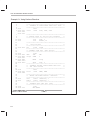
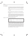
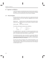
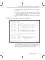
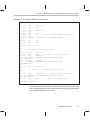
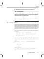
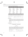
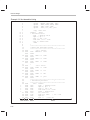
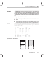
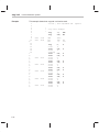
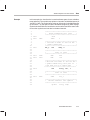
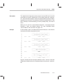
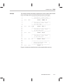
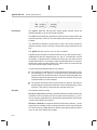
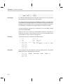
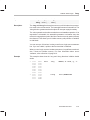
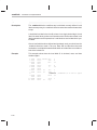
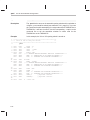
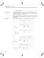
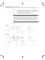
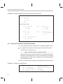
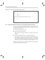
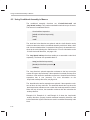
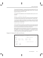
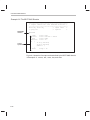
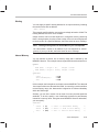
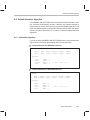
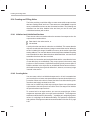
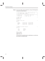
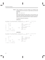
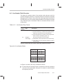
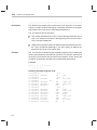
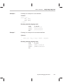
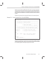
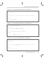
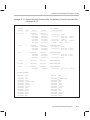
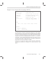
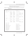
Program listings, program examples, and interactive displays are shown
in a special font. Examples use a bold version of the special font for emphasis. Here is a sample program listing:
11
12
13
14
0005
0005
0005
0006
0001
0003
0006
.field
.field
.field
.even
1, 2
3, 4
6, 3
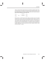
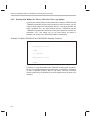
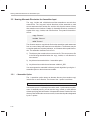
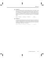
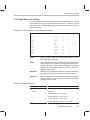
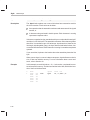
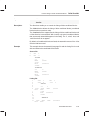
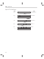
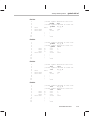
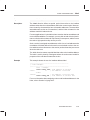
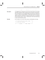
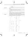
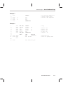
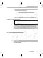
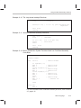
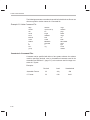
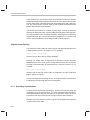
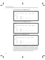
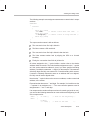
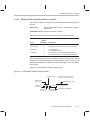
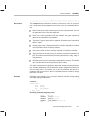
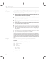
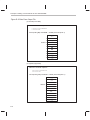
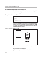
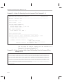
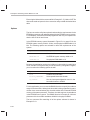
In syntax descriptions, the instruction, command, or directive is in a bold
face font and parameters are in an italics. Portions of a syntax that are in
bold face should be entered as shown; portions of a syntax that are in italics describe the type of information that should be entered. Syntax that will
be entered on a command line is centered in a bounded box. Syntax that
will be used in a text file is left-justified in an unbounded box. Here is an
example of command line syntax:
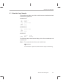
dspabs
filename
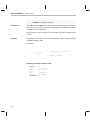
dspabs is a command. The command invokes the absolute lister and has
one parameter, indicated by filename. When you invoke the absolute lister, you supply the name of the file that the absolute lister uses as input.
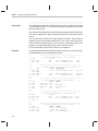
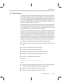
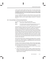
-
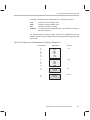
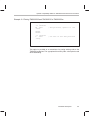
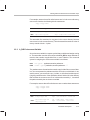
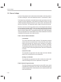
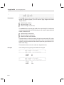
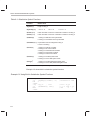
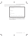
Square brackets ( [ and ] ) identify an optional parameter. If you use an
optional parameter, you specify the information within the brackets; you
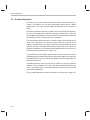
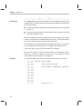
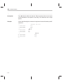
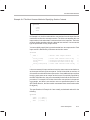
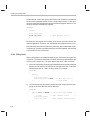
don’t enter the brackets themselves. Here’s an example of an instruction
that has an optional parameter:
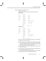
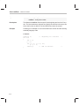
dsphex
iv
[–options] filename
Notational Conventions
The dsphex command has two parameters. The first parameter,
–options, is optional. Since options is plural, you may select several
options. The second parameter, filename, is required.
Square brackets are also used as part of the pathname specification for
VMS pathnames; in this case, the brackets are actually part of the pathname (they are not optional).
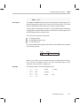
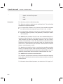
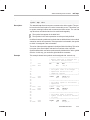
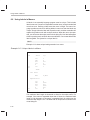
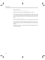
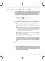
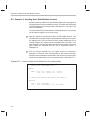
-
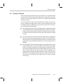
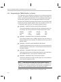
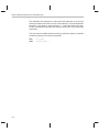
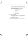
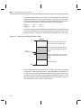
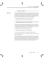
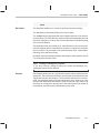
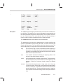
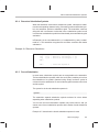
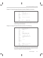
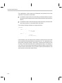
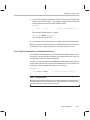
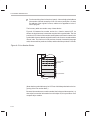
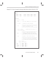
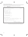
In assembler syntax statements, column one is reserved for the first character of a label or symbol. If the label or symbol is optional, it is usually
not shown. If it is a required parameter, then it will be shown starting
against the left margin of the shaded box, as in the example below. No
instruction, command, directive, or parameter, other than a symbol or
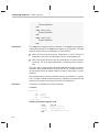
label, should begin in column one.
symbol .usect ”section name”, size in bytes
The symbol is required for the .usect directive and must begin in column
one. The section name must be enclosed in quotes, and the section size in
bytes must be separated from the section name by a comma.
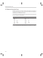
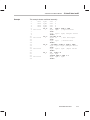
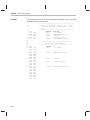
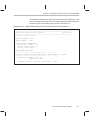
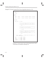
-
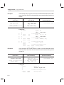
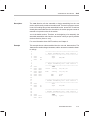
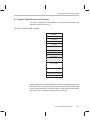
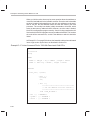
Some directives can have a varying number of parameters. For example,
the .byte directive can have up to 100 parameters. The syntax for this directive is:
.byte value1 [, ... , valuen ]
Note that .byte does not
begin in column one.
This syntax shows that .byte must have at least one value parameter, but
you have the option of supplying additional value parameters, separated
by commas.
-
Braces ( { and } ) indicate a list. The symbol | (read as or) separates items
within the list. Here’s an example of a list:
{ * | *+ | *– }
This provides three choices: *, *+, or *–.
Unless the list is enclosed in square brackets, you must choose one item
from the list.
Read This First
v
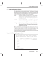
Related Documentation From Texas Instruments
Related Documentation From Texas Instruments
The following books describe the TMS320C1x, ’C2x, ’C2xx, and ’C5x devices
and related support tools. To obtain a copy of any of these TI documents, call
the Texas Instruments Literature Response Center at (800) 477–8924. When
ordering, please identify the book by its title and literature number.
TMS320C1x User’s Guide (literature number SPRU013) discusses the
hardware aspects of the ’C1x generation of CMOS fixed-point digital
signal processors. It describes pin assignments, architecture, instruction
set, and software and hardware applications. This book also features a
section with analog interface peripherals and applications for the ’C1x
DSPs, and includes a consolidated data sheet with electrical
specifications and package information for all ’C1x devices.
TMS320C2x User’s Guide (literature number SPRU014) discusses the hardware aspects of the ’C2x fixed-point digital signal processors. It describes pin assignments, architecture, instruction set, and software and
hardware applications. It also includes electrical specifications and package mechanical data for all ’C2x devices. The book features a section
with a ’C1x-to-’C2x DSP system migration.
TMS320C2xx User’s Guide (literature number SPRU127) discusses the
hardware aspects of the ’C2xx fixed-point digital signal processors. It describes pin assignments, architecture, instruction set, and software and
hardware applications. It also includes electrical specifications and package mechanical data for all ’C2xx devices. The book features a section
comparing instructions from ’C2x to ’C2xx.
TMS320C5x User’s Guide (literature number SPRU056) describes the
TMS320C5x 16-bit, fixed-point, general-purpose digital signal processors. Covered are its architecture, internal register structure, instruction
set, pipeline, specifications, DMA, and I/O ports. Software applications
are covered in a dedicated chapter.
TMS320C2x/C2xx/C5x Optimizing C Compiler User’s Guide (literature
number SPRU024) describes the ’C2x/’C2xx/C5x C compiler. This C
compiler accepts ANSI standard C source code and produces TMS320
assembly language source code for the ’C2x, ’C2xx, and ’C5x generations of devices.
TMS320 Family Development Support Reference Guide (literature number
SPRU011) describes the ’320 family of digital signal processors and
covers the various products that support this product line. This includes
code-generation tools (compilers, assemblers, linkers, etc.) and system
integration and debug tools (simulators, emulators, evaluation modules,
etc.). Also covered are available documentation, seminars, the university program, and factory repair and exchange.
vi
Related Documentation From Texas Instruments
TMS320 Third-Party Support Reference Guide (literature number
SPRU052) alphabetically lists over 100 third parties that provided various products that serve the family of ’320 digital signal processors. A
myriad of products and applications are offered—software and hardware
development tools, speech recognition, image processing, noise cancellation, modems, etc.
Digital Signal Processing Applications with the TMS320 Family, Volumes
1, 2, and 3 (literature numbers SPRA012, SPRA016, SPRA017)
Volumes 1 and 2 cover applications using the ’C10 and ’C20 families of
fixed-point processors. Volume 3 documents applications using both
fixed-point processors as well as the ’C30 floating-point processor.
TMS320C2x C Source Debugger User’s Guide (literature number
SPRU070) tells how to invoke the debugger with the TMS320C2x
simulator version of the C source debugger interface. This book discusses various aspects of the debugger interface, including window
management, command entry, code execution, data management,
and breakpoints, and includes a tutorial that introduces basic debugger functionality.
TMS320C5x C Source Debugger User’s Guide (literature number
SPRU055) tells you how to invoke the ’C5x emulator, EVM, and simulator
versions of the C source debugger interface. This book discusses
various aspects of the debugger interface, including window
management, command entry, code execution, data management, and
breakpoints, and includes a tutorial that introduces basic debugger
functionality.
Read This First
vii
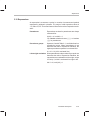
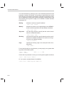
If You Need Assistance... / Trademarks
If You Need Assistance. . .
If you want to. . .
Do this. . .
Request more information about Texas
Instruments Digital Signal Processing
(DSP) products
Call the DSP hotline:
(713) 274–2320
FAX: (713) 274–2324
Order Texas Instruments documentation
Call the TI Literature Response Ctr:
(800) 477–8924
Ask questions about product operation or
report suspected problems
Call the DSP hotline:
(713) 274–2320
FAX: (713) 274–2324
Report mistakes or make comments about
this, or any other TI documentation
Send your comments to
[email protected]
Please mention the full title of the book
and the date of publication (from the spine
and/or front cover) in your correspondence.
Texas Instruments Incorporated
Technical Publications Mgr, MS 702
P.O. Box 1443
Houston, Texas 77251–1443
Trademarks
IBM, PC, PC-DOS and OS/2 are trademarks of International Business Machines Corp.
MS, MS-DOS, and MS-Windows are registered trademarks of Microsoft Corp.
SPARC is a trademark of SPARC International, Inc.
SunView, SunWindows, and Sun Workstation are trademarks of Sun Microsystems, Inc.
UNIX is a registered trademark of Unix System Laboratories, Inc.
XDS is a trademark of Texas Instruments Incorporated.
viii
Running Title—Attribute Reference
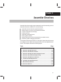
Contents
1
Introduction . . . . . . . . . . . . . . . . . . . . . . . . . . . . . . . . . . . . . . . . . . . . . . . . . . . . . . . . . . . . . . . . . . . . . 1-1
Provides an overview of the assembly language development tools.
1.1
1.2
2
Introduction to Common Object File Format . . . . . . . . . . . . . . . . . . . . . . . . . . . . . . . . . . . . . . 2-1
Discusses the basic COFF concept of sections and how they can help you use the assembler
and linker more efficiently. Common object file format, or COFF, is the object file format used
by the TMS320 fixed-point tools. Read Chapter 2 before using the assembler and linker.
2.1
2.2
2.3
2.4
2.5
2.6
2.7
3
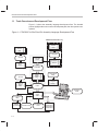
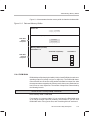
Tools Overview and Development Flow . . . . . . . . . . . . . . . . . . . . . . . . . . . . . . . . . . . . . . . . 1-2
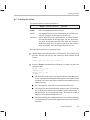
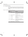
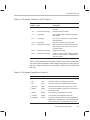
Tools Descriptions . . . . . . . . . . . . . . . . . . . . . . . . . . . . . . . . . . . . . . . . . . . . . . . . . . . . . . . . . . 1-3
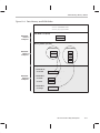
Sections . . . . . . . . . . . . . . . . . . . . . . . . . . . . . . . . . . . . . . . . . . . . . . . . . . . . . . . . . . . . . . . . . . . 2-2
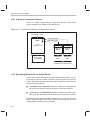
How the Assembler Handles Sections . . . . . . . . . . . . . . . . . . . . . . . . . . . . . . . . . . . . . . . . . 2-4
2.2.1 Uninitialized Sections . . . . . . . . . . . . . . . . . . . . . . . . . . . . . . . . . . . . . . . . . . . . . . . . 2-4
2.2.2 Initialized Sections . . . . . . . . . . . . . . . . . . . . . . . . . . . . . . . . . . . . . . . . . . . . . . . . . . . 2-5
2.2.3 Named Sections . . . . . . . . . . . . . . . . . . . . . . . . . . . . . . . . . . . . . . . . . . . . . . . . . . . . . 2-6
2.2.4 Section Program Counters . . . . . . . . . . . . . . . . . . . . . . . . . . . . . . . . . . . . . . . . . . . . 2-7
2.2.5 Absolute Sections . . . . . . . . . . . . . . . . . . . . . . . . . . . . . . . . . . . . . . . . . . . . . . . . . . . 2-7
2.2.6 An Example That Uses Sections Directives . . . . . . . . . . . . . . . . . . . . . . . . . . . . . 2-7
How the Linker Handles Sections . . . . . . . . . . . . . . . . . . . . . . . . . . . . . . . . . . . . . . . . . . . . 2-10
2.3.1 Default Memory Allocation . . . . . . . . . . . . . . . . . . . . . . . . . . . . . . . . . . . . . . . . . . . 2-11
2.3.2 Placing Sections in the Memory Map . . . . . . . . . . . . . . . . . . . . . . . . . . . . . . . . . . 2-14
Relocation . . . . . . . . . . . . . . . . . . . . . . . . . . . . . . . . . . . . . . . . . . . . . . . . . . . . . . . . . . . . . . . . 2-18
Runtime Relocation . . . . . . . . . . . . . . . . . . . . . . . . . . . . . . . . . . . . . . . . . . . . . . . . . . . . . . . . 2-20
Loading a Program . . . . . . . . . . . . . . . . . . . . . . . . . . . . . . . . . . . . . . . . . . . . . . . . . . . . . . . . 2-21
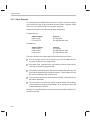
Symbols in a COFF File . . . . . . . . . . . . . . . . . . . . . . . . . . . . . . . . . . . . . . . . . . . . . . . . . . . . 2-22
2.7.1 External Symbols . . . . . . . . . . . . . . . . . . . . . . . . . . . . . . . . . . . . . . . . . . . . . . . . . . . 2-22
2.7.2 The Symbol Table . . . . . . . . . . . . . . . . . . . . . . . . . . . . . . . . . . . . . . . . . . . . . . . . . . 2-23
Assembler Description . . . . . . . . . . . . . . . . . . . . . . . . . . . . . . . . . . . . . . . . . . . . . . . . . . . . . . . . . . . 3-1
Explains how to invoke the assembler and discusses source statement format, valid constants
and expressions, and assembler output.
3.1
3.2
3.3
3.4
Assembler Overview . . . . . . . . . . . . . . . . . . . . . . . . . . . . . . . . . . . . . . . . . . . . . . . . . . . . . . . . 3-2
Assembler Development Flow . . . . . . . . . . . . . . . . . . . . . . . . . . . . . . . . . . . . . . . . . . . . . . . . 3-3
Invoking the Assembler . . . . . . . . . . . . . . . . . . . . . . . . . . . . . . . . . . . . . . . . . . . . . . . . . . . . . . 3-4
Upward Compatibility Within the TMS320C1x/C2x/C2xx/C5x Processors . . . . . . . . . . 3-6
3.4.1 Porting Inconsistencies (–p Option) . . . . . . . . . . . . . . . . . . . . . . . . . . . . . . . . . . . . 3-6
3.4.2 Porting Code Written for ’C2x or ’C5x to the ’C2xx (–pp Option) . . . . . . . . . . . 3-8
3.4.3 Programming the TMS320 Pipeline (–w Option) . . . . . . . . . . . . . . . . . . . . . . . . 3-10
ix
Contents
3.5
3.6
3.7
3.8
3.9
3.10
3.11
3.12
3.13
4
3-12
3-12
3-13
3-15
3-15
3-16
3-16
3-16
3-17
3-17
3-17
3-17
3-18
3-18
3-18
3-19
3-20
3-20
3-20
3-21
3-21
3-23
3-24
3-25
3-26
3-26
3-27
3-27
3-27
3-30
3-33
3-34
Assembler Directives . . . . . . . . . . . . . . . . . . . . . . . . . . . . . . . . . . . . . . . . . . . . . . . . . . . . . . . . . . . . 4-1
Describes the directives according to function, and presents the directives in alphabetical order.
4.1
4.2
4.3
4.4
4.5
4.6
4.7
4.8
4.9
4.10
x
Naming Alternate Directories for Assembler Input . . . . . . . . . . . . . . . . . . . . . . . . . . . . . .
3.5.1 –i Assembler Option . . . . . . . . . . . . . . . . . . . . . . . . . . . . . . . . . . . . . . . . . . . . . . . .
3.5.2 A_DIR Environment Variable . . . . . . . . . . . . . . . . . . . . . . . . . . . . . . . . . . . . . . . . .
Source Statement Format . . . . . . . . . . . . . . . . . . . . . . . . . . . . . . . . . . . . . . . . . . . . . . . . . .
3.6.1 Label Field . . . . . . . . . . . . . . . . . . . . . . . . . . . . . . . . . . . . . . . . . . . . . . . . . . . . . . . .
3.6.2 Mnemonic Field . . . . . . . . . . . . . . . . . . . . . . . . . . . . . . . . . . . . . . . . . . . . . . . . . . . .
3.6.3 Operand Field . . . . . . . . . . . . . . . . . . . . . . . . . . . . . . . . . . . . . . . . . . . . . . . . . . . . . .
3.6.4 Comment Field . . . . . . . . . . . . . . . . . . . . . . . . . . . . . . . . . . . . . . . . . . . . . . . . . . . . .
Constants . . . . . . . . . . . . . . . . . . . . . . . . . . . . . . . . . . . . . . . . . . . . . . . . . . . . . . . . . . . . . . . .
3.7.1 Binary Integers . . . . . . . . . . . . . . . . . . . . . . . . . . . . . . . . . . . . . . . . . . . . . . . . . . . . .
3.7.2 Octal Integers . . . . . . . . . . . . . . . . . . . . . . . . . . . . . . . . . . . . . . . . . . . . . . . . . . . . . .
3.7.3 Decimal Integers . . . . . . . . . . . . . . . . . . . . . . . . . . . . . . . . . . . . . . . . . . . . . . . . . . .
3.7.4 Hexadecimal Integers . . . . . . . . . . . . . . . . . . . . . . . . . . . . . . . . . . . . . . . . . . . . . . .
3.7.5 Character Constants . . . . . . . . . . . . . . . . . . . . . . . . . . . . . . . . . . . . . . . . . . . . . . . .
3.7.6 Assembly-Time Constants . . . . . . . . . . . . . . . . . . . . . . . . . . . . . . . . . . . . . . . . . . .
Character Strings . . . . . . . . . . . . . . . . . . . . . . . . . . . . . . . . . . . . . . . . . . . . . . . . . . . . . . . . . .
Symbols . . . . . . . . . . . . . . . . . . . . . . . . . . . . . . . . . . . . . . . . . . . . . . . . . . . . . . . . . . . . . . . . . .
3.9.1 Labels . . . . . . . . . . . . . . . . . . . . . . . . . . . . . . . . . . . . . . . . . . . . . . . . . . . . . . . . . . . .
3.9.2 Symbolic Constants . . . . . . . . . . . . . . . . . . . . . . . . . . . . . . . . . . . . . . . . . . . . . . . . .
3.9.3 Defining Symbolic Constants (–d Option) . . . . . . . . . . . . . . . . . . . . . . . . . . . . . .
3.9.4 Predefined Symbolic Constants . . . . . . . . . . . . . . . . . . . . . . . . . . . . . . . . . . . . . .
3.9.5 Substitution Symbols . . . . . . . . . . . . . . . . . . . . . . . . . . . . . . . . . . . . . . . . . . . . . . . .
3.9.6 Local Labels . . . . . . . . . . . . . . . . . . . . . . . . . . . . . . . . . . . . . . . . . . . . . . . . . . . . . . .
Expressions . . . . . . . . . . . . . . . . . . . . . . . . . . . . . . . . . . . . . . . . . . . . . . . . . . . . . . . . . . . . . . .
3.10.1 Operators . . . . . . . . . . . . . . . . . . . . . . . . . . . . . . . . . . . . . . . . . . . . . . . . . . . . . . . . .
3.10.2 Expression Overflow and Underflow . . . . . . . . . . . . . . . . . . . . . . . . . . . . . . . . . .
3.10.3 Well-Defined Expressions . . . . . . . . . . . . . . . . . . . . . . . . . . . . . . . . . . . . . . . . . . .
3.10.4 Conditional Expressions . . . . . . . . . . . . . . . . . . . . . . . . . . . . . . . . . . . . . . . . . . . . .
3.10.5 Relocatable Symbols and Legal Expressions . . . . . . . . . . . . . . . . . . . . . . . . . . .
Source Listings . . . . . . . . . . . . . . . . . . . . . . . . . . . . . . . . . . . . . . . . . . . . . . . . . . . . . . . . . . . .
Cross-Reference Listings . . . . . . . . . . . . . . . . . . . . . . . . . . . . . . . . . . . . . . . . . . . . . . . . . . .
Enhanced Instruction Forms . . . . . . . . . . . . . . . . . . . . . . . . . . . . . . . . . . . . . . . . . . . . . . . .
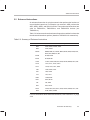
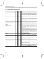
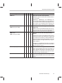
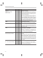
Directives Summary . . . . . . . . . . . . . . . . . . . . . . . . . . . . . . . . . . . . . . . . . . . . . . . . . . . . . . . . 4-2
Directives That Define Sections . . . . . . . . . . . . . . . . . . . . . . . . . . . . . . . . . . . . . . . . . . . . . . 4-6
Directives That Initialize Constants . . . . . . . . . . . . . . . . . . . . . . . . . . . . . . . . . . . . . . . . . . . . 4-8
Directives That Align the Section Program Counter . . . . . . . . . . . . . . . . . . . . . . . . . . . . . 4-11
Directives That Format the Output Listing . . . . . . . . . . . . . . . . . . . . . . . . . . . . . . . . . . . . . 4-12
Directives That Reference Other Files . . . . . . . . . . . . . . . . . . . . . . . . . . . . . . . . . . . . . . . . 4-14
Conditional Assembly Directives . . . . . . . . . . . . . . . . . . . . . . . . . . . . . . . . . . . . . . . . . . . . . 4-15
Assembly-Time Symbol Directives . . . . . . . . . . . . . . . . . . . . . . . . . . . . . . . . . . . . . . . . . . . 4-16
Miscellaneous Directives . . . . . . . . . . . . . . . . . . . . . . . . . . . . . . . . . . . . . . . . . . . . . . . . . . . 4-18
Directives Reference . . . . . . . . . . . . . . . . . . . . . . . . . . . . . . . . . . . . . . . . . . . . . . . . . . . . . . . 4-20
Contents
5
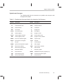
Instruction Set Summary . . . . . . . . . . . . . . . . . . . . . . . . . . . . . . . . . . . . . . . . . . . . . . . . . . . . . . . . . 5-1
Summarizes the TMS320C1x, TMS320C2x, TMS320C2xx, and TMS320C5x instruction sets
alphabetically. This chapter also discusses enhanced instructions.
5.1
5.2
5.3
6
Macro Language . . . . . . . . . . . . . . . . . . . . . . . . . . . . . . . . . . . . . . . . . . . . . . . . . . . . . . . . . . . . . . . . 6-1
Describes macro directives, substitution symbols used as macro parameters, and how to
create macros.
6.1
6.2
6.3
6.4
6.5
6.6
6.7
6.8
6.9
6.10
7
Using Macros . . . . . . . . . . . . . . . . . . . . . . . . . . . . . . . . . . . . . . . . . . . . . . . . . . . . . . . . . . . . . . 6-2
Defining Macros . . . . . . . . . . . . . . . . . . . . . . . . . . . . . . . . . . . . . . . . . . . . . . . . . . . . . . . . . . . . 6-3
Macro Parameters/Substitution Symbols . . . . . . . . . . . . . . . . . . . . . . . . . . . . . . . . . . . . . . . 6-5
6.3.1 Substitution Symbols . . . . . . . . . . . . . . . . . . . . . . . . . . . . . . . . . . . . . . . . . . . . . . . . . 6-5
6.3.2 Directives That Define Substitution Symbols . . . . . . . . . . . . . . . . . . . . . . . . . . . . 6-6
6.3.3 Built-In Substitution Symbol Functions . . . . . . . . . . . . . . . . . . . . . . . . . . . . . . . . . 6-7
6.3.4 Recursive Substitution Symbols . . . . . . . . . . . . . . . . . . . . . . . . . . . . . . . . . . . . . . . 6-9
6.3.5 Forced Substitution . . . . . . . . . . . . . . . . . . . . . . . . . . . . . . . . . . . . . . . . . . . . . . . . . . 6-9
6.3.6 Accessing Individual Characters of Subscripted Substitution Symbols . . . . . 6-10
6.3.7 Substitution Symbols as Local Variables in Macros . . . . . . . . . . . . . . . . . . . . . . 6-12
Macro Libraries . . . . . . . . . . . . . . . . . . . . . . . . . . . . . . . . . . . . . . . . . . . . . . . . . . . . . . . . . . . . 6-13
Using Conditional Assembly in Macros . . . . . . . . . . . . . . . . . . . . . . . . . . . . . . . . . . . . . . . 6-14
Using Labels in Macros . . . . . . . . . . . . . . . . . . . . . . . . . . . . . . . . . . . . . . . . . . . . . . . . . . . . . 6-16
Producing Messages in Macros . . . . . . . . . . . . . . . . . . . . . . . . . . . . . . . . . . . . . . . . . . . . . 6-17
Formatting the Output Listing . . . . . . . . . . . . . . . . . . . . . . . . . . . . . . . . . . . . . . . . . . . . . . . . 6-18
Using Recursive and Nested Macros . . . . . . . . . . . . . . . . . . . . . . . . . . . . . . . . . . . . . . . . . 6-19
Macro Directives Summary . . . . . . . . . . . . . . . . . . . . . . . . . . . . . . . . . . . . . . . . . . . . . . . . . 6-21
Archiver Description . . . . . . . . . . . . . . . . . . . . . . . . . . . . . . . . . . . . . . . . . . . . . . . . . . . . . . . . . . . . . 7-1
Contains instructions for invoking the archiver, creating new archive libraries, and modifying
existing libraries.
7.1
7.2
7.3
7.4
8
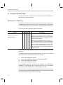
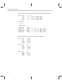
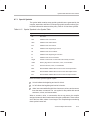
Using the Summary Table . . . . . . . . . . . . . . . . . . . . . . . . . . . . . . . . . . . . . . . . . . . . . . . . . . . 5-2
Enhanced Instructions . . . . . . . . . . . . . . . . . . . . . . . . . . . . . . . . . . . . . . . . . . . . . . . . . . . . . . . 5-5
Instruction Set Summary Table . . . . . . . . . . . . . . . . . . . . . . . . . . . . . . . . . . . . . . . . . . . . . . . 5-6
Archiver Overview . . . . . . . . . . . . . . . . . . . . . . . . . . . . . . . . . . . . . . . . . . . . . . . . . . . . . . . . . .
Archiver Development Flow . . . . . . . . . . . . . . . . . . . . . . . . . . . . . . . . . . . . . . . . . . . . . . . . . .
Invoking the Archiver . . . . . . . . . . . . . . . . . . . . . . . . . . . . . . . . . . . . . . . . . . . . . . . . . . . . . . . .
Archiver Examples . . . . . . . . . . . . . . . . . . . . . . . . . . . . . . . . . . . . . . . . . . . . . . . . . . . . . . . . . .
7-2
7-3
7-4
7-6
Linker Description . . . . . . . . . . . . . . . . . . . . . . . . . . . . . . . . . . . . . . . . . . . . . . . . . . . . . . . . . . . . . . . 8-1
Explains how to invoke the linker, provides details about linker operation, discusses linker directives, and presents a detailed linking example.
8.1
8.2
8.3
Linker Development Flow . . . . . . . . . . . . . . . . . . . . . . . . . . . . . . . . . . . . . . . . . . . . . . . . . . . .
Invoking the Linker . . . . . . . . . . . . . . . . . . . . . . . . . . . . . . . . . . . . . . . . . . . . . . . . . . . . . . . . . .
Linker Options . . . . . . . . . . . . . . . . . . . . . . . . . . . . . . . . . . . . . . . . . . . . . . . . . . . . . . . . . . . . .
8.3.1 Relocation Capabilities (–a and –r Options) . . . . . . . . . . . . . . . . . . . . . . . . . . . . .
8.3.2 Disable Merge of Symbolic Debugging Information (–b Option) . . . . . . . . . . . .
Contents
8-2
8-3
8-5
8-6
8-7
xi
Contents
8.4
8.5
8.6
8.7
8.8
8.9
8.10
8.11
8.12
8.13
xii
8.3.3 C Language Options (–c and –cr Options) . . . . . . . . . . . . . . . . . . . . . . . . . . . . . . 8-8
8.3.4 Define an Entry Point (–e global symbol Option) . . . . . . . . . . . . . . . . . . . . . . . . . 8-8
8.3.5 Set Default Value (–f cc Option) . . . . . . . . . . . . . . . . . . . . . . . . . . . . . . . . . . . . . . . 8-8
8.3.6 Make All Global Symbols Static (–h Option) . . . . . . . . . . . . . . . . . . . . . . . . . . . . . 8-9
8.3.7 Define Heap Size (–heap constant Option) . . . . . . . . . . . . . . . . . . . . . . . . . . . . . . 8-9
8.3.8 Alter the Library Search Algorithm (–i dir Option/C_DIR) . . . . . . . . . . . . . . . . . 8-10
8.3.9 Create a Map File (–m filename Option) . . . . . . . . . . . . . . . . . . . . . . . . . . . . . . . 8-12
8.3.10 Name an Output Module (–o filename Option) . . . . . . . . . . . . . . . . . . . . . . . . . . 8-12
8.3.11 Specify a Quiet Run (–q Option) . . . . . . . . . . . . . . . . . . . . . . . . . . . . . . . . . . . . . . 8-12
8.3.12 Strip Symbolic Information (–s Option) . . . . . . . . . . . . . . . . . . . . . . . . . . . . . . . . 8-13
8.3.13 Define Stack Size (–stack constant Option) . . . . . . . . . . . . . . . . . . . . . . . . . . . . 8-13
8.3.14 Introduce an Unresolved Symbol (–u symbol Option) . . . . . . . . . . . . . . . . . . . . 8-13
8.3.15 Generate Version 0 COFF format (–v0 Option) . . . . . . . . . . . . . . . . . . . . . . . . . 8-14
8.3.16 Warning Switch (–w Option) . . . . . . . . . . . . . . . . . . . . . . . . . . . . . . . . . . . . . . . . . 8-14
8.3.17 Exhaustively Read Libraries (–x Option) . . . . . . . . . . . . . . . . . . . . . . . . . . . . . . . 8-15
Linker Command Files . . . . . . . . . . . . . . . . . . . . . . . . . . . . . . . . . . . . . . . . . . . . . . . . . . . . . 8-16
Object Libraries . . . . . . . . . . . . . . . . . . . . . . . . . . . . . . . . . . . . . . . . . . . . . . . . . . . . . . . . . . . 8-19
The MEMORY Directive . . . . . . . . . . . . . . . . . . . . . . . . . . . . . . . . . . . . . . . . . . . . . . . . . . . . 8-21
8.6.1 Default Memory Model . . . . . . . . . . . . . . . . . . . . . . . . . . . . . . . . . . . . . . . . . . . . . . 8-21
8.6.2 MEMORY Directive Syntax . . . . . . . . . . . . . . . . . . . . . . . . . . . . . . . . . . . . . . . . . . 8-21
The SECTIONS Directive . . . . . . . . . . . . . . . . . . . . . . . . . . . . . . . . . . . . . . . . . . . . . . . . . . . 8-24
8.7.1 Default Sections Configuration . . . . . . . . . . . . . . . . . . . . . . . . . . . . . . . . . . . . . . . 8-24
8.7.2 SECTIONS Directive Syntax . . . . . . . . . . . . . . . . . . . . . . . . . . . . . . . . . . . . . . . . . 8-24
8.7.3 Specifying the Address of Output Sections (Allocation) . . . . . . . . . . . . . . . . . . 8-27
8.7.4 Specifying Input Sections . . . . . . . . . . . . . . . . . . . . . . . . . . . . . . . . . . . . . . . . . . . . 8-30
Specifying a Section’s Runtime Address . . . . . . . . . . . . . . . . . . . . . . . . . . . . . . . . . . . . . . 8-33
8.8.1 Specifying Load and Run Addresses . . . . . . . . . . . . . . . . . . . . . . . . . . . . . . . . . . 8-33
8.8.2 Uninitialized Sections . . . . . . . . . . . . . . . . . . . . . . . . . . . . . . . . . . . . . . . . . . . . . . . 8-34
8.8.3 Referring to the Load Address by Using the .label Directive . . . . . . . . . . . . . . 8-34
Using UNION and GROUP Statements . . . . . . . . . . . . . . . . . . . . . . . . . . . . . . . . . . . . . . . 8-37
8.9.1 Overlaying Sections With the UNION Statement . . . . . . . . . . . . . . . . . . . . . . . . 8-37
8.9.2 Grouping Output Sections Together . . . . . . . . . . . . . . . . . . . . . . . . . . . . . . . . . . . 8-39
Overlay Pages . . . . . . . . . . . . . . . . . . . . . . . . . . . . . . . . . . . . . . . . . . . . . . . . . . . . . . . . . . . . 8-40
8.10.1 Using the MEMORY Directive to Define Overlay Pages . . . . . . . . . . . . . . . . . . 8-40
8.10.2 Using Overlay Pages With the SECTIONS Directive . . . . . . . . . . . . . . . . . . . . 8-42
8.10.3 Page Definition Syntax . . . . . . . . . . . . . . . . . . . . . . . . . . . . . . . . . . . . . . . . . . . . . . 8-43
Default Allocation Algorithm . . . . . . . . . . . . . . . . . . . . . . . . . . . . . . . . . . . . . . . . . . . . . . . . . 8-45
8.11.1 Allocation Algorithm . . . . . . . . . . . . . . . . . . . . . . . . . . . . . . . . . . . . . . . . . . . . . . . . . 8-45
8.11.2 General Rules for Forming Output Sections . . . . . . . . . . . . . . . . . . . . . . . . . . . . 8-47
Special Section Types (DSECT, COPY, and NOLOAD) . . . . . . . . . . . . . . . . . . . . . . . . . 8-49
Assigning Symbols at Link Time . . . . . . . . . . . . . . . . . . . . . . . . . . . . . . . . . . . . . . . . . . . . . 8-50
8.13.1 Syntax of Assignment Statements . . . . . . . . . . . . . . . . . . . . . . . . . . . . . . . . . . . . 8-50
8.13.2 Assigning the SPC to a Symbol . . . . . . . . . . . . . . . . . . . . . . . . . . . . . . . . . . . . . . 8-50
8.13.3 Assignment Expressions . . . . . . . . . . . . . . . . . . . . . . . . . . . . . . . . . . . . . . . . . . . . 8-51
8.13.4 Symbols Defined by the Linker . . . . . . . . . . . . . . . . . . . . . . . . . . . . . . . . . . . . . . . 8-53
Contents
8.14
8.15
8.16
8.17
9
Creating and Filling Holes . . . . . . . . . . . . . . . . . . . . . . . . . . . . . . . . . . . . . . . . . . . . . . . . . .
8.14.1 Initialized and Uninitialized Sections . . . . . . . . . . . . . . . . . . . . . . . . . . . . . . . . . .
8.14.2 Creating Holes . . . . . . . . . . . . . . . . . . . . . . . . . . . . . . . . . . . . . . . . . . . . . . . . . . . . .
8.14.3 Filling Holes . . . . . . . . . . . . . . . . . . . . . . . . . . . . . . . . . . . . . . . . . . . . . . . . . . . . . . .
8.14.4 Explicit Initialization of Uninitialized Sections . . . . . . . . . . . . . . . . . . . . . . . . . . .
Partial (Incremental) Linking . . . . . . . . . . . . . . . . . . . . . . . . . . . . . . . . . . . . . . . . . . . . . . . .
Linking C Code . . . . . . . . . . . . . . . . . . . . . . . . . . . . . . . . . . . . . . . . . . . . . . . . . . . . . . . . . . . .
8.16.1 Runtime Initialization . . . . . . . . . . . . . . . . . . . . . . . . . . . . . . . . . . . . . . . . . . . . . . . .
8.16.2 Object Libraries and Runtime Support . . . . . . . . . . . . . . . . . . . . . . . . . . . . . . . . .
8.16.3 Setting the Size of the Heap and Stack Sections . . . . . . . . . . . . . . . . . . . . . . . .
8.16.4 Autoinitialization (ROM and RAM Models) . . . . . . . . . . . . . . . . . . . . . . . . . . . . .
8.16.5 The –c and –cr Linker Options . . . . . . . . . . . . . . . . . . . . . . . . . . . . . . . . . . . . . . .
Linker Example . . . . . . . . . . . . . . . . . . . . . . . . . . . . . . . . . . . . . . . . . . . . . . . . . . . . . . . . . . . .
8-54
8-54
8-54
8-56
8-57
8-58
8-60
8-60
8-60
8-61
8-61
8-63
8-64
Absolute Lister Description . . . . . . . . . . . . . . . . . . . . . . . . . . . . . . . . . . . . . . . . . . . . . . . . . . . . . . 9-1
Explains how to invoke the absolute lister to obtain a listing of the absolute addresses of an
object file.
9.1
9.2
9.3
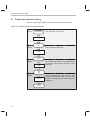
Producing an Absolute Listing . . . . . . . . . . . . . . . . . . . . . . . . . . . . . . . . . . . . . . . . . . . . . . . . 9-2
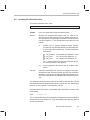
Invoking the Absolute Lister . . . . . . . . . . . . . . . . . . . . . . . . . . . . . . . . . . . . . . . . . . . . . . . . . . 9-3
Absolute Lister Example . . . . . . . . . . . . . . . . . . . . . . . . . . . . . . . . . . . . . . . . . . . . . . . . . . . . . 9-5
10 Cross-Reference Lister . . . . . . . . . . . . . . . . . . . . . . . . . . . . . . . . . . . . . . . . . . . . . . . . . . . . . . . . . 10-1
Explains how to invoke the cross-reference lister to obtain a listing of symbols, their definitions,
and their references in the linked source files.
10.1
10.2
10.3
Producing a Cross-Reference Listing . . . . . . . . . . . . . . . . . . . . . . . . . . . . . . . . . . . . . . . . . 10-2
Invoking the Cross-Reference Lister . . . . . . . . . . . . . . . . . . . . . . . . . . . . . . . . . . . . . . . . . 10-3
Cross-Reference Listing Example . . . . . . . . . . . . . . . . . . . . . . . . . . . . . . . . . . . . . . . . . . . . 10-4
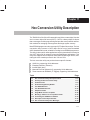
11 Hex Conversion Utility Description . . . . . . . . . . . . . . . . . . . . . . . . . . . . . . . . . . . . . . . . . . . . . . 11-1
Explains how to invoke the hex utility to convert a COFF object file into one of several standard
hexadecimal formats suitable for loading into an EPROM programmer.
11.1
11.2
11.3
11.4
11.5
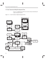
Hex Conversion Utility Development Flow . . . . . . . . . . . . . . . . . . . . . . . . . . . . . . . . . . . . . 11-2
Invoking the Hex Conversion Utility . . . . . . . . . . . . . . . . . . . . . . . . . . . . . . . . . . . . . . . . . . 11-3
Command Files . . . . . . . . . . . . . . . . . . . . . . . . . . . . . . . . . . . . . . . . . . . . . . . . . . . . . . . . . . . 11-5
Understanding Memory Widths . . . . . . . . . . . . . . . . . . . . . . . . . . . . . . . . . . . . . . . . . . . . . . 11-7
11.4.1 Target Width . . . . . . . . . . . . . . . . . . . . . . . . . . . . . . . . . . . . . . . . . . . . . . . . . . . . . . . 11-8
11.4.2 Data Width . . . . . . . . . . . . . . . . . . . . . . . . . . . . . . . . . . . . . . . . . . . . . . . . . . . . . . . . 11-8
11.4.3 Memory Width . . . . . . . . . . . . . . . . . . . . . . . . . . . . . . . . . . . . . . . . . . . . . . . . . . . . . 11-8
11.4.4 ROM Width . . . . . . . . . . . . . . . . . . . . . . . . . . . . . . . . . . . . . . . . . . . . . . . . . . . . . . . . 11-9
11.4.5 A Memory Configuration Example . . . . . . . . . . . . . . . . . . . . . . . . . . . . . . . . . . . 11-12
11.4.6 Specifying Word Order for Output Words . . . . . . . . . . . . . . . . . . . . . . . . . . . . . 11-12
The ROMS Directive . . . . . . . . . . . . . . . . . . . . . . . . . . . . . . . . . . . . . . . . . . . . . . . . . . . . . . 11-14
11.5.1 When to Use the ROMS Directive . . . . . . . . . . . . . . . . . . . . . . . . . . . . . . . . . . . 11-16
11.5.2 An Example of the ROMS Directive . . . . . . . . . . . . . . . . . . . . . . . . . . . . . . . . . . 11-17
11.5.3 Creating a Map File of the ROMS directive . . . . . . . . . . . . . . . . . . . . . . . . . . . . 11-19
Contents
xiii
Contents
11.6
11.7
11.8
The SECTIONS Directive . . . . . . . . . . . . . . . . . . . . . . . . . . . . . . . . . . . . . . . . . . . . . . . . . .
Output Filenames . . . . . . . . . . . . . . . . . . . . . . . . . . . . . . . . . . . . . . . . . . . . . . . . . . . . . . . . .
Image Mode and the –fill Option . . . . . . . . . . . . . . . . . . . . . . . . . . . . . . . . . . . . . . . . . . . .
11.8.1 The –image Option . . . . . . . . . . . . . . . . . . . . . . . . . . . . . . . . . . . . . . . . . . . . . . . .
11.8.2 Specifying a Fill Value . . . . . . . . . . . . . . . . . . . . . . . . . . . . . . . . . . . . . . . . . . . . . .
11.8.3 Steps to Follow in Image Mode . . . . . . . . . . . . . . . . . . . . . . . . . . . . . . . . . . . . . .
11.9 Building a Table for an On-Chip Boot Loader . . . . . . . . . . . . . . . . . . . . . . . . . . . . . . . . .
11.9.1 Description of the Boot Table . . . . . . . . . . . . . . . . . . . . . . . . . . . . . . . . . . . . . . . .
11.9.2 The Boot Table Format . . . . . . . . . . . . . . . . . . . . . . . . . . . . . . . . . . . . . . . . . . . . .
11.9.3 How to Build the Boot Table . . . . . . . . . . . . . . . . . . . . . . . . . . . . . . . . . . . . . . . . .
11.9.4 Booting From a Device Peripheral . . . . . . . . . . . . . . . . . . . . . . . . . . . . . . . . . . .
11.9.5 Setting the Entry Point for the Boot Table . . . . . . . . . . . . . . . . . . . . . . . . . . . . .
11.9.6 Using the ’C26 Boot Loader . . . . . . . . . . . . . . . . . . . . . . . . . . . . . . . . . . . . . . . . .
11.9.7 Using the ’C5x Boot Loader . . . . . . . . . . . . . . . . . . . . . . . . . . . . . . . . . . . . . . . . .
11.10 Controlling the ROM Device Address . . . . . . . . . . . . . . . . . . . . . . . . . . . . . . . . . . . . . . . .
11.10.1 Controlling the Starting Address . . . . . . . . . . . . . . . . . . . . . . . . . . . . . . . . . . . . .
11.10.2 Controlling the Address Increment Index . . . . . . . . . . . . . . . . . . . . . . . . . . . . .
11.10.3 The –byte Option . . . . . . . . . . . . . . . . . . . . . . . . . . . . . . . . . . . . . . . . . . . . . . . . . .
11.10.4 Dealing With Address Holes . . . . . . . . . . . . . . . . . . . . . . . . . . . . . . . . . . . . . . . .
11.11 Description of the Object Formats . . . . . . . . . . . . . . . . . . . . . . . . . . . . . . . . . . . . . . . . . . .
11.11.1 ASCII-Hex Object Format (–a Option) . . . . . . . . . . . . . . . . . . . . . . . . . . . . . . . .
11.11.2 Intel MCS-86 Object Format (–i Option) . . . . . . . . . . . . . . . . . . . . . . . . . . . . . .
11.11.3 Motorola Exorciser Object Format (–m Option) . . . . . . . . . . . . . . . . . . . . . . . .
11.11.4 Texas Instruments SDSMAC Object Format (–t Option) . . . . . . . . . . . . . . . . .
11.11.5 Extended Tektronix Object Format (–x Option) . . . . . . . . . . . . . . . . . . . . . . . .
11.12 Hex Conversion Utility Error Messages . . . . . . . . . . . . . . . . . . . . . . . . . . . . . . . . . . . . . .
A
Common Object File Format . . . . . . . . . . . . . . . . . . . . . . . . . . . . . . . . . . . . . . . . . . . . . . . . . . . . . . A-1
Contains supplemental technical data about the internal format and structure of COFF object
files.
A.1
A.2
A.3
A.4
A.5
A.6
A.7
xiv
11-20
11-22
11-24
11-24
11-25
11-25
11-26
11-26
11-26
11-27
11-28
11-29
11-30
11-32
11-34
11-34
11-36
11-36
11-37
11-38
11-39
11-40
11-41
11-42
11-43
11-44
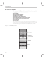
COFF File Structure . . . . . . . . . . . . . . . . . . . . . . . . . . . . . . . . . . . . . . . . . . . . . . . . . . . . . . . . A-2
File Header Structure . . . . . . . . . . . . . . . . . . . . . . . . . . . . . . . . . . . . . . . . . . . . . . . . . . . . . . . A-4
Optional File Header Format . . . . . . . . . . . . . . . . . . . . . . . . . . . . . . . . . . . . . . . . . . . . . . . . . A-6
Section Header Structure . . . . . . . . . . . . . . . . . . . . . . . . . . . . . . . . . . . . . . . . . . . . . . . . . . . . A-7
Structuring Relocation Information . . . . . . . . . . . . . . . . . . . . . . . . . . . . . . . . . . . . . . . . . . . . A-9
Line Number Table Structure . . . . . . . . . . . . . . . . . . . . . . . . . . . . . . . . . . . . . . . . . . . . . . . . A-11
Symbol Table Structure and Content . . . . . . . . . . . . . . . . . . . . . . . . . . . . . . . . . . . . . . . . . A-13
A.7.1 Special Symbols . . . . . . . . . . . . . . . . . . . . . . . . . . . . . . . . . . . . . . . . . . . . . . . . . . . A-15
A.7.2 Symbol Name Format . . . . . . . . . . . . . . . . . . . . . . . . . . . . . . . . . . . . . . . . . . . . . . . A-17
A.7.3 String Table Structure . . . . . . . . . . . . . . . . . . . . . . . . . . . . . . . . . . . . . . . . . . . . . . . A-17
A.7.4 Storage Classes . . . . . . . . . . . . . . . . . . . . . . . . . . . . . . . . . . . . . . . . . . . . . . . . . . . . A-18
A.7.5 Symbol Values . . . . . . . . . . . . . . . . . . . . . . . . . . . . . . . . . . . . . . . . . . . . . . . . . . . . . A-19
A.7.6 Section Number . . . . . . . . . . . . . . . . . . . . . . . . . . . . . . . . . . . . . . . . . . . . . . . . . . . . A-20
A.7.7 Type Entry . . . . . . . . . . . . . . . . . . . . . . . . . . . . . . . . . . . . . . . . . . . . . . . . . . . . . . . . . A-20
A.7.8 Auxiliary Entries . . . . . . . . . . . . . . . . . . . . . . . . . . . . . . . . . . . . . . . . . . . . . . . . . . . . A-22
Contents
B
Symbolic Debugging Directives . . . . . . . . . . . . . . . . . . . . . . . . . . . . . . . . . . . . . . . . . . . . . . . . . . B-1
Discusses symbolic debugging directives that the TMS320C2x/C5x C compiler uses.
C
Example Linker Command Files . . . . . . . . . . . . . . . . . . . . . . . . . . . . . . . . . . . . . . . . . . . . . . . . . . C-1
Provides examples of linker command files for the TMS320C10, TMS320C25, TMS320C50,
and TMS320C51.
C.1
C.2
C.3
C.4
D
Linker Command Files for the TMS320C10
Linker Command Files for the TMS320C25
Linker Command Files for the TMS320C50
Linker Command Files for the TMS320C51
....................................
....................................
....................................
....................................
C-2
C-3
C-5
C-7
Hex Conversion Utility Examples . . . . . . . . . . . . . . . . . . . . . . . . . . . . . . . . . . . . . . . . . . . . . . . . . D-1
Illustrates command file development for a variety of memory systems and situations.
D.1
D.2
D.3
D.4
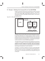
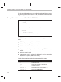
Example 1: Building a Hex Command File for Two 8-Bit EPROMs . . . . . . . . . . . . . . . . . D-2
Example 2: Avoiding Holes With Multiple Sections . . . . . . . . . . . . . . . . . . . . . . . . . . . . . . D-7
Example 3: Generating a Boot Table for a ’C50 . . . . . . . . . . . . . . . . . . . . . . . . . . . . . . . . . D-9
Example 4: Generating a Boot Table for a ’C26 . . . . . . . . . . . . . . . . . . . . . . . . . . . . . . . . D-18
E
Assembler Error Messages . . . . . . . . . . . . . . . . . . . . . . . . . . . . . . . . . . . . . . . . . . . . . . . . . . . . . . . E-1
Lists the error messages that the assembler issues, and gives a description of the condition
which caused each error.
F
Linker Error Messages . . . . . . . . . . . . . . . . . . . . . . . . . . . . . . . . . . . . . . . . . . . . . . . . . . . . . . . . . . . F-1
Lists the syntax and command, allocation, and I/O error messages that the linker issues, and
gives a description of the condition which caused each error.
G
Glossary . . . . . . . . . . . . . . . . . . . . . . . . . . . . . . . . . . . . . . . . . . . . . . . . . . . . . . . . . . . . . . . . . . . . . . . . G-1
Defines terms and acronyms used in this book.
Contents
xv
Running Title—Attribute Reference
Figures
1–1
2–1
2–2
2–3
2–4
2–5
2–6
3–1
4–1
4–2
4–3
4–4
4–5
4–6
4–7
4–8
4–9
4–10
7–1
8–1
8–2
8–3
8–4
8–5
8–6
8–7
8–8
9–1
10–1
11–1
11–2
11–3
11–4
11–5
11–6
11–7
xvi
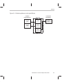
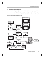
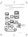
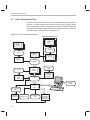
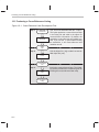
TMS320C1x/C2x/C2xx/C5x Assembly Language Development Flow . . . . . . . . . . . . . . . . 1-2
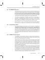
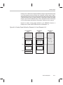
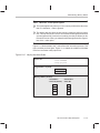
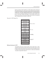
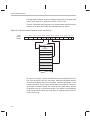
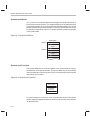
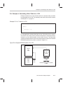
Partitioning Memory Into Logical Blocks . . . . . . . . . . . . . . . . . . . . . . . . . . . . . . . . . . . . . . . . . . 2-3
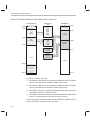
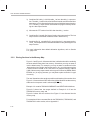
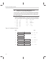
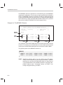
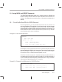
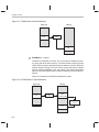
Object Code Generated by the Listing in Example 2–1 . . . . . . . . . . . . . . . . . . . . . . . . . . . . . 2-9
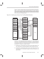
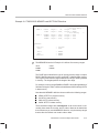
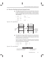
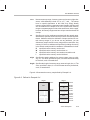
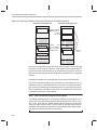
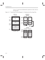
Default Allocation for the Object Code in Figure 2–2 . . . . . . . . . . . . . . . . . . . . . . . . . . . . . . 2-12
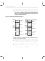
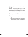
Combining Input Sections From Two Files (Default Allocation) . . . . . . . . . . . . . . . . . . . . . 2-13
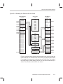
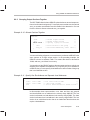
Memory Map Defined by Example 2–2 . . . . . . . . . . . . . . . . . . . . . . . . . . . . . . . . . . . . . . . . . . 2-16
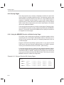
Allocating the Sections With the Linker . . . . . . . . . . . . . . . . . . . . . . . . . . . . . . . . . . . . . . . . . . 2-17
Assembler Development Flow . . . . . . . . . . . . . . . . . . . . . . . . . . . . . . . . . . . . . . . . . . . . . . . . . . 3-3
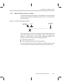
The .space and .bes Directives . . . . . . . . . . . . . . . . . . . . . . . . . . . . . . . . . . . . . . . . . . . . . . . . . 4-8
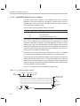
The .field Directive . . . . . . . . . . . . . . . . . . . . . . . . . . . . . . . . . . . . . . . . . . . . . . . . . . . . . . . . . . . . 4-9
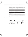
Initialization Directives . . . . . . . . . . . . . . . . . . . . . . . . . . . . . . . . . . . . . . . . . . . . . . . . . . . . . . . . 4-10
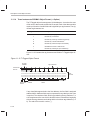
The .align Directive . . . . . . . . . . . . . . . . . . . . . . . . . . . . . . . . . . . . . . . . . . . . . . . . . . . . . . . . . . . 4-11
The .even Directive . . . . . . . . . . . . . . . . . . . . . . . . . . . . . . . . . . . . . . . . . . . . . . . . . . . . . . . . . . . 4-11
The .align Directive . . . . . . . . . . . . . . . . . . . . . . . . . . . . . . . . . . . . . . . . . . . . . . . . . . . . . . . . . . . 4-21
Allocating .bss Blocks Within a Page . . . . . . . . . . . . . . . . . . . . . . . . . . . . . . . . . . . . . . . . . . . 4-26
The .even Directive . . . . . . . . . . . . . . . . . . . . . . . . . . . . . . . . . . . . . . . . . . . . . . . . . . . . . . . . . . . 4-38
The .field Directive . . . . . . . . . . . . . . . . . . . . . . . . . . . . . . . . . . . . . . . . . . . . . . . . . . . . . . . . . . . 4-42
The .usect Directive . . . . . . . . . . . . . . . . . . . . . . . . . . . . . . . . . . . . . . . . . . . . . . . . . . . . . . . . . . 4-78
Archiver Development Flow . . . . . . . . . . . . . . . . . . . . . . . . . . . . . . . . . . . . . . . . . . . . . . . . . . . . 7-3
Linker Development Flow . . . . . . . . . . . . . . . . . . . . . . . . . . . . . . . . . . . . . . . . . . . . . . . . . . . . . . 8-2
Defined in Example 8–4 . . . . . . . . . . . . . . . . . . . . . . . . . . . . . . . . . . . . . . . . . . . . . . . . . . . . . . 8-23
Section Allocation Defined by Example 8–5 . . . . . . . . . . . . . . . . . . . . . . . . . . . . . . . . . . . . . . 8-27
Runtime Execution of Example 8–7 . . . . . . . . . . . . . . . . . . . . . . . . . . . . . . . . . . . . . . . . . . . . . 8-36
Memory Allocation Defined by Example 8–8 and Example 8–9 . . . . . . . . . . . . . . . . . . . . . 8-38
Overlay Pages Defined by Example 8–12 and Example 8–13 . . . . . . . . . . . . . . . . . . . . . . 8-41
RAM Model of Autoinitialization . . . . . . . . . . . . . . . . . . . . . . . . . . . . . . . . . . . . . . . . . . . . . . . . 8-62
ROM Model of Autoinitialization . . . . . . . . . . . . . . . . . . . . . . . . . . . . . . . . . . . . . . . . . . . . . . . . 8-62
Absolute Lister Development Flow . . . . . . . . . . . . . . . . . . . . . . . . . . . . . . . . . . . . . . . . . . . . . . 9-2
Cross-Reference Lister Development Flow . . . . . . . . . . . . . . . . . . . . . . . . . . . . . . . . . . . . . . 10-2
Hex Conversion Utility Development Flow . . . . . . . . . . . . . . . . . . . . . . . . . . . . . . . . . . . . . . . 11-2
Hex Conversion Utility Process Flow . . . . . . . . . . . . . . . . . . . . . . . . . . . . . . . . . . . . . . . . . . . 11-7
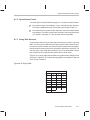
Data and Memory Widths . . . . . . . . . . . . . . . . . . . . . . . . . . . . . . . . . . . . . . . . . . . . . . . . . . . . . 11-9
Data, Memory, and ROM Widths . . . . . . . . . . . . . . . . . . . . . . . . . . . . . . . . . . . . . . . . . . . . . . 11-11
’C2x/C2xx/C5x Memory Configuration Example . . . . . . . . . . . . . . . . . . . . . . . . . . . . . . . . . 11-12
Varying the Word Order . . . . . . . . . . . . . . . . . . . . . . . . . . . . . . . . . . . . . . . . . . . . . . . . . . . . . . 11-13
The infile.out File From Example 11–1 Partitioned Into Four Output Files . . . . . . . . . . . 11-18
Figures
11–8
11–9
11–10
11–11
11–12
11–13
11–14
A–1
A–2
A–3
A–4
A–5
A–6
A–7
A–8
A–9
D–2
D–3
D–4
Sample Command File for Booting From a ’C5x EPROM . . . . . . . . . . . . . . . . . . . . . . . . . 11-33
Hex Command File for Avoiding a Hole at the Beginning of a Section . . . . . . . . . . . . . . 11-37
ASCII-Hex Object Format . . . . . . . . . . . . . . . . . . . . . . . . . . . . . . . . . . . . . . . . . . . . . . . . . . . . 11-39
Intel Hex Object Format . . . . . . . . . . . . . . . . . . . . . . . . . . . . . . . . . . . . . . . . . . . . . . . . . . . . . . 11-40
Motorola-S Format . . . . . . . . . . . . . . . . . . . . . . . . . . . . . . . . . . . . . . . . . . . . . . . . . . . . . . . . . . 11-41
TI-Tagged Object Format . . . . . . . . . . . . . . . . . . . . . . . . . . . . . . . . . . . . . . . . . . . . . . . . . . . . . 11-42
Extended Tektronix Object Format . . . . . . . . . . . . . . . . . . . . . . . . . . . . . . . . . . . . . . . . . . . . . 11-43
COFF File Structure . . . . . . . . . . . . . . . . . . . . . . . . . . . . . . . . . . . . . . . . . . . . . . . . . . . . . . . . . . . A-2
COFF Object File . . . . . . . . . . . . . . . . . . . . . . . . . . . . . . . . . . . . . . . . . . . . . . . . . . . . . . . . . . . . . A-3
Section Header Pointers for the .text Section . . . . . . . . . . . . . . . . . . . . . . . . . . . . . . . . . . . . . A-8
Line Number Blocks . . . . . . . . . . . . . . . . . . . . . . . . . . . . . . . . . . . . . . . . . . . . . . . . . . . . . . . . . . A-11
Line Number Entries . . . . . . . . . . . . . . . . . . . . . . . . . . . . . . . . . . . . . . . . . . . . . . . . . . . . . . . . . . A-12
Symbol Table Contents . . . . . . . . . . . . . . . . . . . . . . . . . . . . . . . . . . . . . . . . . . . . . . . . . . . . . . . A-13
Symbols for Blocks . . . . . . . . . . . . . . . . . . . . . . . . . . . . . . . . . . . . . . . . . . . . . . . . . . . . . . . . . . . A-16
Symbols for Functions . . . . . . . . . . . . . . . . . . . . . . . . . . . . . . . . . . . . . . . . . . . . . . . . . . . . . . . . A-16
String Table . . . . . . . . . . . . . . . . . . . . . . . . . . . . . . . . . . . . . . . . . . . . . . . . . . . . . . . . . . . . . . . . . A-17
Data From Output File . . . . . . . . . . . . . . . . . . . . . . . . . . . . . . . . . . . . . . . . . . . . . . . . . . . . . . . . . D-5
EPROM System for a ’C50 . . . . . . . . . . . . . . . . . . . . . . . . . . . . . . . . . . . . . . . . . . . . . . . . . . . . . D-9
Sample EPROM System for a ’C26 . . . . . . . . . . . . . . . . . . . . . . . . . . . . . . . . . . . . . . . . . . . . . D-18
Contents
xvii
Running Title—Attribute Reference
Tables
1–1
3–1
3–2
3–3
4–1
4–2
5–1
5–2
6–1
6–2
6–3
6–4
6–5
6–6
8–1
8–2
10–1
11–1
11–2
11–3
A–1
A–2
A–3
A–4
A–5
A–6
A–7
A–8
A–9
A–10
A–11
A–12
A–13
A–14
A–15
A–16
xviii
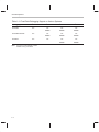
Fixed-Point Debugging Support on Various Systems . . . . . . . . . . . . . . . . . . . . . . . . . . . . . . . 1-4
Operators Used in Expressions (Precedence) . . . . . . . . . . . . . . . . . . . . . . . . . . . . . . . . . . . . 3-26
Expressions With Absolute and Relocatable Symbols . . . . . . . . . . . . . . . . . . . . . . . . . . . . . 3-28
Symbol Attributes . . . . . . . . . . . . . . . . . . . . . . . . . . . . . . . . . . . . . . . . . . . . . . . . . . . . . . . . . . . . 3-33
Assembler Directives Summary . . . . . . . . . . . . . . . . . . . . . . . . . . . . . . . . . . . . . . . . . . . . . . . . . 4-2
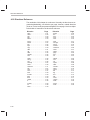
Memory-Mapped Registers . . . . . . . . . . . . . . . . . . . . . . . . . . . . . . . . . . . . . . . . . . . . . . . . . . . . 5-58
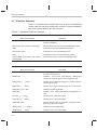
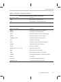
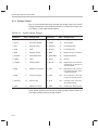
Symbols and Acronyms Used in the Instruction Set Summary . . . . . . . . . . . . . . . . . . . . . . . 5-3
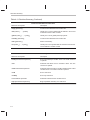
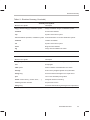
Summary of Enhanced Instructions . . . . . . . . . . . . . . . . . . . . . . . . . . . . . . . . . . . . . . . . . . . . . . 5-5
Substitution Symbol Functions . . . . . . . . . . . . . . . . . . . . . . . . . . . . . . . . . . . . . . . . . . . . . . . . . . 6-8
Creating Macros . . . . . . . . . . . . . . . . . . . . . . . . . . . . . . . . . . . . . . . . . . . . . . . . . . . . . . . . . . . . . 6-21
Manipulating Substitution Symbols . . . . . . . . . . . . . . . . . . . . . . . . . . . . . . . . . . . . . . . . . . . . . 6-21
Conditional Assembly . . . . . . . . . . . . . . . . . . . . . . . . . . . . . . . . . . . . . . . . . . . . . . . . . . . . . . . . . 6-21
Producing Assembly-Time Messages . . . . . . . . . . . . . . . . . . . . . . . . . . . . . . . . . . . . . . . . . . . 6-22
Formatting the Listing . . . . . . . . . . . . . . . . . . . . . . . . . . . . . . . . . . . . . . . . . . . . . . . . . . . . . . . . . 6-22
Linker Options Summary . . . . . . . . . . . . . . . . . . . . . . . . . . . . . . . . . . . . . . . . . . . . . . . . . . . . . . . 8-5
Operators in Assignment Expressions . . . . . . . . . . . . . . . . . . . . . . . . . . . . . . . . . . . . . . . . . . 8-52
Symbol Attributes . . . . . . . . . . . . . . . . . . . . . . . . . . . . . . . . . . . . . . . . . . . . . . . . . . . . . . . . . . . . 10-5
Basic Options . . . . . . . . . . . . . . . . . . . . . . . . . . . . . . . . . . . . . . . . . . . . . . . . . . . . . . . . . . . . . . . 11-4
Boot-Loader Utility Options . . . . . . . . . . . . . . . . . . . . . . . . . . . . . . . . . . . . . . . . . . . . . . . . . . . 11-27
Options for Specifying Hex Conversion Formats . . . . . . . . . . . . . . . . . . . . . . . . . . . . . . . . . 11-38
File Header Contents for COFF Version 0 . . . . . . . . . . . . . . . . . . . . . . . . . . . . . . . . . . . . . . . . A-4
File Header Contents for COFF Version 1 . . . . . . . . . . . . . . . . . . . . . . . . . . . . . . . . . . . . . . . . A-5
File Header Flags (Bytes 18 and 19) . . . . . . . . . . . . . . . . . . . . . . . . . . . . . . . . . . . . . . . . . . . . . A-5
Optional File Header Contents . . . . . . . . . . . . . . . . . . . . . . . . . . . . . . . . . . . . . . . . . . . . . . . . . . A-6
Section Header Contents . . . . . . . . . . . . . . . . . . . . . . . . . . . . . . . . . . . . . . . . . . . . . . . . . . . . . . A-7
Section Header Flags (Bytes 36 and 37) . . . . . . . . . . . . . . . . . . . . . . . . . . . . . . . . . . . . . . . . . A-7
Relocation Entry Contents for COFF Version 0 . . . . . . . . . . . . . . . . . . . . . . . . . . . . . . . . . . . . A-9
Relocation Entry Contents for COFF Version 1 . . . . . . . . . . . . . . . . . . . . . . . . . . . . . . . . . . . . A-9
Relocation Types (Bytes 8 and 9) . . . . . . . . . . . . . . . . . . . . . . . . . . . . . . . . . . . . . . . . . . . . . . A-10
Line Number Entry Format . . . . . . . . . . . . . . . . . . . . . . . . . . . . . . . . . . . . . . . . . . . . . . . . . . . . A-11
Symbol Table Entry Contents . . . . . . . . . . . . . . . . . . . . . . . . . . . . . . . . . . . . . . . . . . . . . . . . . . A-14
Special Symbols in the Symbol Table . . . . . . . . . . . . . . . . . . . . . . . . . . . . . . . . . . . . . . . . . . . A-15
Symbol Storage Classes . . . . . . . . . . . . . . . . . . . . . . . . . . . . . . . . . . . . . . . . . . . . . . . . . . . . . . A-18
Special Symbols and Their Storage Classes . . . . . . . . . . . . . . . . . . . . . . . . . . . . . . . . . . . . . A-19
Symbol Values and Storage Classes . . . . . . . . . . . . . . . . . . . . . . . . . . . . . . . . . . . . . . . . . . . A-19
Section Numbers . . . . . . . . . . . . . . . . . . . . . . . . . . . . . . . . . . . . . . . . . . . . . . . . . . . . . . . . . . . . A-20
Tables
A–17
A–18
A–19
A–20
A–21
A–22
A–23
A–24
A–25
A–26
A–27
A–28
Basic Types . . . . . . . . . . . . . . . . . . . . . . . . . . . . . . . . . . . . . . . . . . . . . . . . . . . . . . . . . . . . . . . . .
Derived Types . . . . . . . . . . . . . . . . . . . . . . . . . . . . . . . . . . . . . . . . . . . . . . . . . . . . . . . . . . . . . . .
Auxiliary Symbol Table Entries Format . . . . . . . . . . . . . . . . . . . . . . . . . . . . . . . . . . . . . . . . . .
Filename Format for Auxiliary Table Entries . . . . . . . . . . . . . . . . . . . . . . . . . . . . . . . . . . . . . .
Section Format for Auxiliary Table Entries . . . . . . . . . . . . . . . . . . . . . . . . . . . . . . . . . . . . . . .
Tag Name Format for Auxiliary Table Entries . . . . . . . . . . . . . . . . . . . . . . . . . . . . . . . . . . . . .
End-of-Structure Format for Auxiliary Table Entries . . . . . . . . . . . . . . . . . . . . . . . . . . . . . . .
Function Format for Auxiliary Table Entries . . . . . . . . . . . . . . . . . . . . . . . . . . . . . . . . . . . . . .
Array Format for Auxiliary Table Entries . . . . . . . . . . . . . . . . . . . . . . . . . . . . . . . . . . . . . . . . .
End-of-Blocks/Functions Format for Auxiliary Table Entries . . . . . . . . . . . . . . . . . . . . . . . .
Beginning-of-Blocks/Functions Format for Auxiliary Table Entries . . . . . . . . . . . . . . . . . . .
Structure, Union, and Enumeration Names Format for Auxiliary Table Entries . . . . . . . .
Contents
A-21
A-21
A-22
A-23
A-23
A-23
A-24
A-24
A-25
A-25
A-26
A-26
xix
Running Title—Attribute Reference
Examples
2–1
2–2
2–3
3–1
3–2
3–3
3–4
3–5
3–6
4–1
6–1
6–2
6–3
6–4
6–5
6–6
6–7
6–8
6–9
6–10
6–11
6–12
6–13
6–14
6–15
6–16
8–1
8–2
8–3
8–4
8–5
8–6
8–7
8–8
8–9
8–10
xx
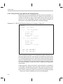
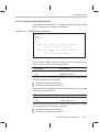
Using Sections Directives . . . . . . . . . . . . . . . . . . . . . . . . . . . . . . . . . . . . . . . . . . . . . . . . . . . . . . 2-8
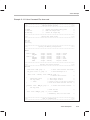
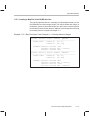
TMS320C25 MEMORY and SECTIONS Directives . . . . . . . . . . . . . . . . . . . . . . . . . . . . . . . 2-15
Code That Generates Relocation Entries . . . . . . . . . . . . . . . . . . . . . . . . . . . . . . . . . . . . . . . . 2-18
–p Option and –v50 Option Effect on Ported Code . . . . . . . . . . . . . . . . . . . . . . . . . . . . . . . . . 3-7
Basic TMS320C25 and TMS320C50 Assembly Construct . . . . . . . . . . . . . . . . . . . . . . . . . . 3-8
Porting TMS320C25 and TMS320C50 to TMS320C2xx . . . . . . . . . . . . . . . . . . . . . . . . . . . . 3-9
–w Option Effect on Ported Code . . . . . . . . . . . . . . . . . . . . . . . . . . . . . . . . . . . . . . . . . . . . . . . 3-11
An Assembler Listing . . . . . . . . . . . . . . . . . . . . . . . . . . . . . . . . . . . . . . . . . . . . . . . . . . . . . . . . . 3-32
An Assembler Cross-Reference Listing . . . . . . . . . . . . . . . . . . . . . . . . . . . . . . . . . . . . . . . . . 3-33
Sections Directives . . . . . . . . . . . . . . . . . . . . . . . . . . . . . . . . . . . . . . . . . . . . . . . . . . . . . . . . . . . . 4-7
Macro Definition, Call, and Expansion . . . . . . . . . . . . . . . . . . . . . . . . . . . . . . . . . . . . . . . . . . . 6-4
Calling a Macro With Varying Numbers of Arguments . . . . . . . . . . . . . . . . . . . . . . . . . . . . . . 6-6
Using the .asg Directive . . . . . . . . . . . . . . . . . . . . . . . . . . . . . . . . . . . . . . . . . . . . . . . . . . . . . . . . 6-6
Using the .eval Directive . . . . . . . . . . . . . . . . . . . . . . . . . . . . . . . . . . . . . . . . . . . . . . . . . . . . . . . 6-7
Using Built-In Substitution Symbol Functions . . . . . . . . . . . . . . . . . . . . . . . . . . . . . . . . . . . . . 6-8
Recursive Substitution . . . . . . . . . . . . . . . . . . . . . . . . . . . . . . . . . . . . . . . . . . . . . . . . . . . . . . . . . 6-9
Using the Forced Substitution Operator . . . . . . . . . . . . . . . . . . . . . . . . . . . . . . . . . . . . . . . . . 6-10
Using Subscripted Substitution Symbols to Redefine an Instruction . . . . . . . . . . . . . . . . . 6-11
Using Subscripted Substitution Symbols to Find Substrings . . . . . . . . . . . . . . . . . . . . . . . . 6-11
The .loop/.break/.endloop Directives . . . . . . . . . . . . . . . . . . . . . . . . . . . . . . . . . . . . . . . . . . . . 6-15
Nested Conditional Assembly Directives . . . . . . . . . . . . . . . . . . . . . . . . . . . . . . . . . . . . . . . . 6-15
Built-In Substitution Symbol Functions Used in a Conditional Assembly Code Block . . 6-15
Unique Labels in a Macro . . . . . . . . . . . . . . . . . . . . . . . . . . . . . . . . . . . . . . . . . . . . . . . . . . . . . 6-16
Producing Messages in a Macro . . . . . . . . . . . . . . . . . . . . . . . . . . . . . . . . . . . . . . . . . . . . . . . 6-17
Using Nested Macros . . . . . . . . . . . . . . . . . . . . . . . . . . . . . . . . . . . . . . . . . . . . . . . . . . . . . . . . . 6-19
Using Recursive Macros . . . . . . . . . . . . . . . . . . . . . . . . . . . . . . . . . . . . . . . . . . . . . . . . . . . . . . 6-20
Linker Command File . . . . . . . . . . . . . . . . . . . . . . . . . . . . . . . . . . . . . . . . . . . . . . . . . . . . . . . . . 8-16
Command File With Linker Directives . . . . . . . . . . . . . . . . . . . . . . . . . . . . . . . . . . . . . . . . . . . 8-17
Linker Command File . . . . . . . . . . . . . . . . . . . . . . . . . . . . . . . . . . . . . . . . . . . . . . . . . . . . . . . . . 8-18
The MEMORY Directive . . . . . . . . . . . . . . . . . . . . . . . . . . . . . . . . . . . . . . . . . . . . . . . . . . . . . . 8-22
The SECTIONS Directive . . . . . . . . . . . . . . . . . . . . . . . . . . . . . . . . . . . . . . . . . . . . . . . . . . . . . 8-26
The Most Common Method of Specifying Section Contents . . . . . . . . . . . . . . . . . . . . . . . . 8-31
Copying a Section From ROM to RAM . . . . . . . . . . . . . . . . . . . . . . . . . . . . . . . . . . . . . . . . . . 8-35
The UNION Statement . . . . . . . . . . . . . . . . . . . . . . . . . . . . . . . . . . . . . . . . . . . . . . . . . . . . . . . . 8-37
Separate Load Addresses for UNION Sections . . . . . . . . . . . . . . . . . . . . . . . . . . . . . . . . . . . 8-37
Allocate Sections Together . . . . . . . . . . . . . . . . . . . . . . . . . . . . . . . . . . . . . . . . . . . . . . . . . . . . 8-39
Examples
8–11
8–12
8–13
8–14
8–15
11–1
11–2
11–3
C–1
C–2
C–3
C–4
C–5
C–6
C–7
C–8
C–9
C–10
C–11
D–1
D–1
D–2
D–3
D–4
D–5
D–6
D–7
D–8
D–9
D–10
D–11
D–12
D–13
D–14
D–15
D–16
D–17
D–18
D–19
D–21
D–22
Specify One Run Address and Separate Load Addresses . . . . . . . . . . . . . . . . . . . . . . . . . 8-39
Memory Directive With Overlay Pages . . . . . . . . . . . . . . . . . . . . . . . . . . . . . . . . . . . . . . . . . . 8-40
SECTIONS Directive Definition for Overlays in Figure 8–6 . . . . . . . . . . . . . . . . . . . . . . . . . 8-42
Linker Command File, demo.cmd . . . . . . . . . . . . . . . . . . . . . . . . . . . . . . . . . . . . . . . . . . . . . . 8-65
Output Map File, demo.map . . . . . . . . . . . . . . . . . . . . . . . . . . . . . . . . . . . . . . . . . . . . . . . . . . . 8-66
A ROMS Directive Example . . . . . . . . . . . . . . . . . . . . . . . . . . . . . . . . . . . . . . . . . . . . . . . . . . 11-17
Map File Output From Example 11–1 Showing Memory Ranges . . . . . . . . . . . . . . . . . . . 11-19
Sample Command File for Booting From a ’C26 Serial Port . . . . . . . . . . . . . . . . . . . . . . . 11-31
TMS320C10 in Microcomputer Mode . . . . . . . . . . . . . . . . . . . . . . . . . . . . . . . . . . . . . . . . . . . . C-2
TMS320C10 in Microprocessor Mode . . . . . . . . . . . . . . . . . . . . . . . . . . . . . . . . . . . . . . . . . . . . C-2
TMS320C25 in Microprocessor Mode, Block B0 as Data Memory . . . . . . . . . . . . . . . . . . . C-3
TMS320C25 in Microcomputer Mode, Block B0 as Data Memory . . . . . . . . . . . . . . . . . . . . C-3
TMS320C25 in Microprocessor Mode, Block B0 as Program Memory . . . . . . . . . . . . . . . . C-4
TMS320C25 in Microcomputer Mode, Block B0 as Program Memory . . . . . . . . . . . . . . . . C-4
TMS320C50 in Microcomputer Mode, Block B0 as Data Memory . . . . . . . . . . . . . . . . . . . . C-5
TMS320C50 in Microprocessor Mode, Block B0 as Data Memory . . . . . . . . . . . . . . . . . . . C-5
TMS320C50 in Microcomputer Mode, Block B0 as Program Memory . . . . . . . . . . . . . . . . C-6
TMS320C51 in Microcomputer Mode, Block B0 as Data Memory . . . . . . . . . . . . . . . . . . . . C-7
TMS320C51 in Microcomputer Mode, Block B0 as Program Memory . . . . . . . . . . . . . . . . C-7
A Two 8-Bit EPROM System . . . . . . . . . . . . . . . . . . . . . . . . . . . . . . . . . . . . . . . . . . . . . . . . . . . D-2
Assembly Code for Hex Conversion Utility Examples . . . . . . . . . . . . . . . . . . . . . . . . . . . . . . D-1
A Linker Command File for Two 8-Bit EPROMs . . . . . . . . . . . . . . . . . . . . . . . . . . . . . . . . . . . D-3
A Hex Command File for Two 8-Bit EPROMs . . . . . . . . . . . . . . . . . . . . . . . . . . . . . . . . . . . . . D-4
Map File Resulting From Hex Command File in Example D–3 . . . . . . . . . . . . . . . . . . . . . . . D-6
Linker Command File: Method One for Avoiding Holes . . . . . . . . . . . . . . . . . . . . . . . . . . . . . D-7
Hex Command File: Method One for Avoiding Holes . . . . . . . . . . . . . . . . . . . . . . . . . . . . . . . D-8
Linker Command File: Method Two for Avoiding Holes . . . . . . . . . . . . . . . . . . . . . . . . . . . . . D-8
Hex Command File: Method Two for Avoiding Holes . . . . . . . . . . . . . . . . . . . . . . . . . . . . . . . D-8
C Code for a ’C50 . . . . . . . . . . . . . . . . . . . . . . . . . . . . . . . . . . . . . . . . . . . . . . . . . . . . . . . . . . . . . D-9
Linker Command File to Form a Single Boot Section for a ’C50 . . . . . . . . . . . . . . . . . . . . D-11
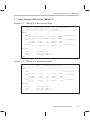
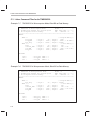
Section Allocation Portion of Map File Resulting From the Command File in
Example D–10 . . . . . . . . . . . . . . . . . . . . . . . . . . . . . . . . . . . . . . . . . . . . . . . . . . . . . . . . . . . . . . . D-12
Linker Command for Setting the Boot Routine Selection Word for a ’C50 . . . . . . . . . . . . D-14
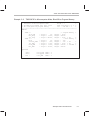
Hex Command File for Converting a COFF File . . . . . . . . . . . . . . . . . . . . . . . . . . . . . . . . . . D-16
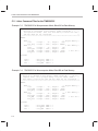
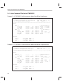
Map File Resulting From the Command File in Example D–13 . . . . . . . . . . . . . . . . . . . . . D-17
Hex Conversion Utility Output File Resulting From the Command File in
Example D–13 . . . . . . . . . . . . . . . . . . . . . . . . . . . . . . . . . . . . . . . . . . . . . . . . . . . . . . . . . . . . . . . D-17
C Code for a ’C26 . . . . . . . . . . . . . . . . . . . . . . . . . . . . . . . . . . . . . . . . . . . . . . . . . . . . . . . . . . . . D-18
Linker Command File for ’C26 With Parent and Child CPUs . . . . . . . . . . . . . . . . . . . . . . . D-19
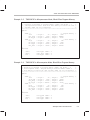
Section Allocation Portion of Map File Resulting From the Command File in
Example D–17 . . . . . . . . . . . . . . . . . . . . . . . . . . . . . . . . . . . . . . . . . . . . . . . . . . . . . . . . . . . . . . . D-20
Hex Command File for ’C26 With Parent and Child CPUs . . . . . . . . . . . . . . . . . . . . . . . . . D-22
Map File (c26boot.mxp) Resulting From the Command File in Example D–19 . . . . . . . . D-23
Output File (c26boot.hex) Resulting From the Command File in Example D–19 . . . . . . D-24
Contents
xxi
Notes, Cautions, and Warnings
Notes
Default Section Directive . . . . . . . . . . . . . . . . . . . . . . . . . . . . . . . . . . . . . . . . . . . . . . . . . . . . . . . . . . . . . . 2-4
The .asect Directive Is Obsolete . . . . . . . . . . . . . . . . . . . . . . . . . . . . . . . . . . . . . . . . . . . . . . . . . . . . . . . . 2-7
Examples in This Section Are for the TMS320C25 . . . . . . . . . . . . . . . . . . . . . . . . . . . . . . . . . . . . . . . 2-10
– w Does Not Provide Warnings for All Pipeline Conflicts . . . . . . . . . . . . . . . . . . . . . . . . . . . . . . . . . 3-10
Register Symbols . . . . . . . . . . . . . . . . . . . . . . . . . . . . . . . . . . . . . . . . . . . . . . . . . . . . . . . . . . . . . . . . . . . 3-23
The .byte, .word, .int, .long, .string, .float, and .field Directives in a .struct/.endstruct Sequence 4-10
The .asect Directive Is Obsolete . . . . . . . . . . . . . . . . . . . . . . . . . . . . . . . . . . . . . . . . . . . . . . . . . . . . . . . 4-22
Use .endm to End a Macro . . . . . . . . . . . . . . . . . . . . . . . . . . . . . . . . . . . . . . . . . . . . . . . . . . . . . . . . . . . 4-36
Creating a Listing File (–l option) . . . . . . . . . . . . . . . . . . . . . . . . . . . . . . . . . . . . . . . . . . . . . . . . . . . . . . 4-51
Directives That Can Appear in a .struct/.endstruct Sequence . . . . . . . . . . . . . . . . . . . . . . . . . . . . . . 4-72
Naming Library Members . . . . . . . . . . . . . . . . . . . . . . . . . . . . . . . . . . . . . . . . . . . . . . . . . . . . . . . . . . . . . . 7-4
Compatibility With Previous Versions . . . . . . . . . . . . . . . . . . . . . . . . . . . . . . . . . . . . . . . . . . . . . . . . . . 8-24
Binding and Alignment or Named Memory Are Incompatible . . . . . . . . . . . . . . . . . . . . . . . . . . . . . . 8-29
The .asect Directive Is Obsolete . . . . . . . . . . . . . . . . . . . . . . . . . . . . . . . . . . . . . . . . . . . . . . . . . . . . . . . 8-34
Union and Overlay Page Are Not the Same . . . . . . . . . . . . . . . . . . . . . . . . . . . . . . . . . . . . . . . . . . . . . 8-38
The PAGE Option . . . . . . . . . . . . . . . . . . . . . . . . . . . . . . . . . . . . . . . . . . . . . . . . . . . . . . . . . . . . . . . . . . . 8-48
Filling Sections . . . . . . . . . . . . . . . . . . . . . . . . . . . . . . . . . . . . . . . . . . . . . . . . . . . . . . . . . . . . . . . . . . . . . . 8-57
The TI-Tagged Format Is 16 Bits Wide . . . . . . . . . . . . . . . . . . . . . . . . . . . . . . . . . . . . . . . . . . . . . . . . 11-10
When the –order Option Applies . . . . . . . . . . . . . . . . . . . . . . . . . . . . . . . . . . . . . . . . . . . . . . . . . . . . . . 11-13
Sections Generated by the C Compiler . . . . . . . . . . . . . . . . . . . . . . . . . . . . . . . . . . . . . . . . . . . . . . . . 11-20
Using the –boot Option and the SECTIONS Directive . . . . . . . . . . . . . . . . . . . . . . . . . . . . . . . . . . . 11-21
Defining the Ranges of Target Memory . . . . . . . . . . . . . . . . . . . . . . . . . . . . . . . . . . . . . . . . . . . . . . . . 11-24
Valid Entry Points . . . . . . . . . . . . . . . . . . . . . . . . . . . . . . . . . . . . . . . . . . . . . . . . . . . . . . . . . . . . . . . . . . 11-29
xxii
Running Title—Attribute Reference
Chapter 1
Introduction
The TMS320C1x/C2x/C2xx/C5x fixed-point DSPs are supported by the
following assembly language tools:
-
Assembler
Archiver
Linker
Absolute lister
Cross-reference lister
Hex conversion utility
This chapter shows how these tools fit into the general software tools development flow and gives a brief description of each tool. For convenience, it also
summarizes the C compiler and debugging tools; however, the compiler and
debugger are not shipped with the assembly language tools. For detailed
information on the compiler and debugger and for complete descriptions of the
TMS320C1x/C2x/C2xx/C5x devices, refer to books listed in Related Documentation From Texas Instruments on page vi.
The assembly language tools create and use object files in common object file
format (COFF) to facilitate modular programming. Object files contain separate blocks (called sections) of code and data that you can load into TMS320
memory spaces. You can program the TMS320 devices more efficiently if you
have a basic understanding of COFF. Chapter 2, Introduction to Common
Object File Format, discusses this object format in detail.
Topic
Page
1.1
Tools Overview and Development Flow . . . . . . . . . . . . . . . . . . . . . . . . . 1-2
1.2
Tools Descriptions . . . . . . . . . . . . . . . . . . . . . . . . . . . . . . . . . . . . . . . . . . . . 1-3
Chapter Title—Attribute Reference
1-1
Tools Overview and Development Flow
1.1 Tools Overview and Development Flow
Figure 1–1 shows the assembly language development flow. The shaded
portion highlights the most common development path; the other portions are
optional.
Figure 1–1. TMS320C1x/C2x/C2xx/C5x Assembly Language Development Flow
TMS320C2x/C2xx/C5xx only
C
Source
Files
Macro
Source
Files
C Compiler
Archiver
Assembler
Source
Assembler
Source
Macro
Library
Assembler
Archiver
Library of
Object
Files
1-2
Library-Build
Utility
RuntimeSupport
Library
Linker
Debugging
Tools
Executable
COFF
File
Hex Conversion
Utility
EPROM
Programmer
COFF
Object
Files
Absolute Lister
Cross-Reference
Lister
TMS320C1x
TMS320C2x
TMS320C2xx
TMS320C5x
Tools Descriptions
1.2 Tools Descriptions
-
-
-
-
-
The TMS320C2x/C2xx/C5x C compiler translates C source code into
TMS320C2x/C2xx/C5x assembly language source code. The C compiler
is not shipped with the assembly language tools package.
The assembler translates assembly language source files into machine
language COFF object files. Source files can contain instructions,
assembler directives, and macro directives. You can use assembler directives to control various aspects of the assembly process, such as the
source listing format, data alignment, and section content.
The archiver allows you to collect a group of files into a single archive file.
For example, you can collect several macros into a macro library. The assembler will search the library and use the members that are called as
macros by the source file. You can also use the archiver to collect a group
of object files into an object library. The linker will include in the library the
members that resolve external references during the link.
The linker combines object files into a single executable COFF object
module. As it creates the executable module, it performs relocation and
resolves external references. The linker accepts relocatable COFF object
files (created by the assembler) as input. It also accepts archiver library
members and output modules created by a previous linker run. Linker
directives allow you to combine object file sections, bind sections or symbols to addresses or within memory ranges, and define or redefine global
symbols.
The absolute lister generates a file that can be reassembled to produce
a listing of the absolute addresses of an object file.
The cross-reference lister uses object files to produce a cross-reference
listing showing symbols, their definition, and their references in the linked
source files.
The TMS320C1x/C2x/C2xx/C5x debugging tools accept COFF files as
input, but most EPROM programmers do not. The hex conversion utility
converts a COFF object file into TI-Tagged, Intel, Motorola, or Tektronix
object format. The converted file can be downloaded to an EPROM programmer.
Table 1–1 lists debugging tools that you can use on various systems to
refine and correct your code before you download it.
Introduction
1-3
Tools Descriptions
Table 1–1. Fixed-Point Debugging Support on Various Systems
Debugging Tools
Simulator
Evaluation Module
Emulator
Note:
1-4
’C1x
’C2x
’C2xx
’C5x
PC
PC
PC
PC
SPARC
SPARC
SPARC
PC
PC
PC
SPARC
SPARC
SPARC
PC
PC
PC
SPARC
SPARC
PC
PC
PC running under MS-DOS or OS/2.
SPARC running under UNIX.
Running Title—Attribute Reference
Chapter 2
Introduction to
Common Object File Format
The assembler and linker create object files that can be executed by a
TMS320C1x/C2x/C2xx/C5x The format of these object files is called common
object file format, or COFF.
COFF makes modular programming easier because it encourages you to
think in terms of blocks of code and data when you write an assembly language
program. These blocks are known as sections. Both the assembler and the
linker provide directives that allow you to create and manipulate sections.
This chapter provides an overview of COFF sections and includes the following topics:
Topic
Page
2.1
Sections . . . . . . . . . . . . . . . . . . . . . . . . . . . . . . . . . . . . . . . . . . . . . . . . . . . . . 2-2
2.2
How the Assembler Handles Sections . . . . . . . . . . . . . . . . . . . . . . . . . . 2-4
2.3
How the Linker Handles Sections . . . . . . . . . . . . . . . . . . . . . . . . . . . . . 2-10
2.4
Relocation . . . . . . . . . . . . . . . . . . . . . . . . . . . . . . . . . . . . . . . . . . . . . . . . . . . 2-18
2.5
Runtime Relocation . . . . . . . . . . . . . . . . . . . . . . . . . . . . . . . . . . . . . . . . . . 2-20
2.6
Loading a Program . . . . . . . . . . . . . . . . . . . . . . . . . . . . . . . . . . . . . . . . . . . 2-21
2.7
Symbols in a COFF File . . . . . . . . . . . . . . . . . . . . . . . . . . . . . . . . . . . . . . . 2-22
For additional information, see Appendix A, which details COFF object file
structure.
Chapter Title—Attribute Reference
2-1
Sections
2.1 Sections
The smallest unit of an object file is called a section. A section is a block of
code or data that will ultimately occupy contiguous space in the memory map.
Each section of an object file is separate and distinct. COFF object files always
contain three default sections:
.text section
.data section
.bss section
usually contains executable code.
usually contains initialized data.
usually reserves space for uninitialized variables.
In addition, the assembler and linker allow you to create, name, and link
named sections that are used like the .data, .text, and .bss sections.
There are two basic types of sections:
Initialized sections
contain data or code. The .text and .data sections
are initialized; named sections created with the
.sect assembler directive are also initialized.
Uninitialized sections
reserve space in the memory map for uninitialized
data. The .bss section is uninitialized; named sections created with the .usect assembler directive are
also uninitialized.
Several assembler directives allow you to associate various portions of code
and data with the appropriate sections. The assembler builds these sections
during the assembly process, creating an object file organized as shown in
Figure 2–1.
One of the linker’s functions is to relocate sections into the target memory map;
this function is called allocation. Because most systems contain several types
of memory, using sections can help you use target memory more efficiently.
All sections are independently relocatable; you can place any section into any
allocated block of target memory. For example, you can define a section that
contains an initialization routine and then allocate the routine into a portion of
the memory map that contains EPROM.
Figure 2–1 shows the relationship between sections in an object file and a
hypothetical target memory.
2-2
Sections
Figure 2–1. Partitioning Memory Into Logical Blocks
Initialized
Program Memory
Object File
Uninitialized
Data Memory
on-chip
ROM
.data
on-chip
RAM
on-chip
ROM
.text
.bss
Introduction to Common Object File Format
2-3
How the Assembler Handles Sections
2.2 How the Assembler Handles Sections
The assembler identifies the portions of an assembly language program that
belong in a section. The assembler has six directives that support this function:
-
.bss
.usect
.text
.data
.sect
.asect
The .bss and .usect directives create uninitialized sections; the .text, .data,
.sect, and .asect directives create initialized sections.
Note: Default Section Directive
If you don’t use any of the sections directives, the assembler assembles
everything into the .text section.
2.2.1
Uninitialized Sections
Uninitialized sections reserve space in TMS320 memory; they are usually allocated into RAM. These sections have no actual contents in the object file; they
simply reserve memory. A program can use this space at runtime for creating
and storing variables.
Uninitialized data areas are built by using the .bss and .usect assembler directives. The .bss directive reserves space in the .bss section. The .usect directive reserves space in a specific uninitialized named section. Each time you
invoke the .bss directive, the assembler reserves more space in the .bss section. Each time you invoke the .usect directive, the assembler reserves more
space in the specified named section.
The syntax for these directives is:
.bss symbol, size in words [blocking flag]
symbol .usect “section name”, size in words, [blocking flag]
2-4
symbol
points to the first byte reserved by this invocation of the .bss
or .usect directive. The symbol corresponds to the name of
the variable that you’re reserving space for. It can be referenced by any other section and can also be declared as a
global symbol (with the .global assembler directive).
size in words
is an absolute expression. The .bss directive reserves size
words in the .bss section; the .usect directive reserves size
words in section name.
How the Assembler Handles Sections
blocking flag
is an optional parameter. If you specify a value greater than
0 for this parameter, the assembler associates size words
contiguously; the allocated space will not cross a page
boundary, unless size is greater than a page, in which case
the object will start on a page boundary.
section name
tells the assembler which named section to reserve space in.
For more information about named sections, refer to subsection 2.2.3.
The .text, .data, .sect, and .asect directives tell the assembler to stop assembling into the current section and begin assembling into the indicated section.
The .bss and .usect directives, however, do not end the current section and
begin a new one; they simply “escape” from the current section temporarily.
The .bss and .usect directives can appear anywhere in an initialized section
without affecting its contents.
2.2.2
Initialized Sections
Initialized sections contain executable code or initialized data. The contents
of these sections are stored in the object file and placed in TMS320 memory
when the program is loaded. Each initialized section is separately relocatable
and may reference symbols that are defined in other sections. The linker automatically resolves these section-relative references.
Four directives tell the assembler to place code or data into a section. The syntaxes for these directives are:
.text
.data
.sect “section name”
.asect “section name” , address
When the assembler encounters one of these directives, it stops assembling
into the current section (acting as an implied “end current section” command).
It then assembles subsequent code into the designated section until it encounters another .text, .data, .sect, or .asect directive.
Sections are built through an iterative process. For example, when the assembler first encounters a .data directive, the .data section is empty. The statements following this first .data directive are assembled into the .data section
(until the assembler encounters a .text, .sect, or .asect directive). If the assembler encounters subsequent .data directives, it adds the statements following
these .data directives to the statements already in the .data section. This
creates a single .data section that can be allocated contiguously into memory.
Introduction to Common Object File Format
2-5
How the Assembler Handles Sections
2.2.3
Named Sections
Named sections are sections that you create. You can use them like the default
.text, .data, and .bss sections, but they are assembled separately.
For example, repeated use of the .text directive builds up a single .text section
in the object file. When linked, this .text section is allocated into memory as a
single unit. Suppose there is a portion of executable code (perhaps an initialization routine) that you don’t want allocated with .text. If you assemble this
segment of code into a named section, it will be assembled separately from
.text, and you will be able to allocate it into memory separately. You can also
assemble initialized data that is separate from the .data section, and you can
reserve space for uninitialized variables that is separate from the .bss section.
Three directives let you create named sections:
-
The .usect directive creates sections that are used like the .bss section.
These sections reserve space in RAM for variables.
The .sect and .asect directives create sections, like the default .text and
.data sections, that can contain code or data. The .sect directive creates
named sections with relocatable addresses; the .asect directive creates
named sections with absolute addresses.
The syntaxes for these directives are:
symbol .usect “section name”, size in words, [blocking flag]
.sect “section name”
.asect “section name” , address
The section name parameter is the name of the section. Section names are
significant to 8 characters. You can create up to 32,767 separate named
sections.
Each time you invoke one of these directives with a new name, you create a
new named section. Each time you invoke one of these directives with a name
that was already used, the assembler assembles code or data (or reserves
space) into the section with that name. You cannot use the same names with
different directives. That is, you cannot create a section with the .usect directive and then try to use the same section with .sect.
The .asect address identifies the section’s absolute starting address in target
memory. This address is required the first time that you assemble into a specific absolute section. If you use .asect to continue assembling into an absolute
section that already contains code, you cannot use the address parameter.
2-6
How the Assembler Handles Sections
2.2.4
Section Program Counters
The assembler maintains a separate program counter for each section. These
program counters are known as section program counters, or SPCs.
An SPC represents the current address within a section of code or data. Initially, the assembler sets each SPC to 0. As the assembler fills a section with
code or data, it increments the appropriate SPC. If you resume assembling into
a section, the assembler remembers the appropriate SPC’s previous value
and continues incrementing the SPC at that point.
The assembler treats each section as if it began at address 0. The linker relocates each section according to its final location in the memory map.
2.2.5
Absolute Sections
The .asect directive defines a named section whose addresses are absolute
with respect to a specified address. Absolute sections are useful for loading
code from off-chip memory into faster on-chip memory.
Note: The .asect Directive Is Obsolete
The .asect directive is obsolete because the linker’s SECTIONS directive
now allows separate load and run addresses for any section; however, the
.asect directive is fully functional to allow compatibility with previous versions
of the assembler. For more information, refer to Section 8.7, page 8-24.
2.2.6
An Example That Uses Sections Directives
Figure 2–1 shows how you can build COFF sections incrementally, using the
sections directives to swap back and forth between the different sections. You
can use sections directives to begin assembling into a section for the first time,
or to continue assembling into a section that already contains code. In the latter
case, the assembler simply appends the new code to the code that is already
in the section.
The format in Example 2–1 is a listing file. Example 2–1 shows how the SPCs
are modified during assembly. A line in a listing file has four fields:
Field 1
Field 2
Field 3
Field 4
contains the source code line counter.
contains the section program counter.
contains the object code.
contains the original source statement.
Introduction to Common Object File Format
2-7
How the Assembler Handles Sections
Example 2–1.Using Sections Directives
1
2
3
4
5 0000
6 0000 0011
0001 0022
0002 0033
7
8
9
10 0000
11 0001
12
13
14
15 0003 0123
16
17
18
19 0000
20 0000 200f
21 0001 d003
0002 0001
22 0003 f280
0004 0001’
23 0005 6000–
24
25
26
27
28 0004
29 0004 00aa
0005 00bb
30
31
32
33 0000
34 0001
35
36
37
38 0006
39 0006 ccff
************************************************
** assemble an initialized table into .data **
************************************************
.data
coeff
.word
011h, 022h, 033h
************************************************
** reserve space in .bss for two variables
**
************************************************
.bss
var1, 1
.bss
buffer, 10
************************************************
**
still in data
**
************************************************
ptr
.word
0123h
************************************************
** assemble code into .text section
**
************************************************
.text
add:
LAC
0Fh
aloop: SBLK
1
BLEZ
SACL
var1, 0
************************************************
** assemble another initialized table into
**
** the .data section
**
************************************************
.data
ivals
.word
0AAh, 0BBh
************************************************
** define the named section ‘‘newvars’’
**
************************************************
var2
.usect ”newvars”, 1
inbuf
.usect ”newvars”, 7
************************************************
** assemble more code into .text
**
************************************************
.text
ADD #0FFh
Field 1 Field 2 Field 3
2-8
aloop
Field 4
How the Assembler Handles Sections
As Figure 2–2 shows, the file in Example 2–1 creates four sections:
.text
.data
.bss
newvars
contains 7 words of object code.
contains 5 words of object code.
reserves 11 words in memory.
is a named section created with the .usect directive; it reserves
8 words in memory.
The second column shows the object code that is assembled into these
sections; the third column shows the source statements that generated the
object code.
Figure 2–2. Object Code Generated by the Listing in Example 2–1
Line Numbers
Object Code
Section
20
21
21
22
22
23
39
200F
D003
0001
F280
0001
6000
CCFF
.text
6
6
6
29
29
0011
0022
0033
00AA
00BB
.data
10
11
No data—
11 words
reserved
.bss
33
34
No data—
8 words
reserved
newvars
Introduction to Common Object File Format
2-9
How the Linker Handles Sections
2.3 How the Linker Handles Sections
The linker has two main functions in regard to sections. First, the linker uses
the sections in COFF object files as building blocks; it combines input sections
(when more than one file is being linked) to create output sections in an executable COFF output module. Second, the linker chooses memory addresses
for the output sections.
Two linker directives support these functions:
-
The MEMORY directive allows you to define the memory map of a target
system. You can name portions of memory and specify their starting addresses and their lengths.
The SECTIONS directive tells the linker how to combine input sections
and where to place the output sections in memory.
It is not always necessary to use linker directives. If you don’t use them, the
linker uses the target processor’s default allocation algorithm described in
subsection 2.3.1. When you do use linker directives, you must specify them
in a linker command file.
Refer to the following sections for more information about linker command files
and linker directives:
Section
Page
8.4
Linker Command Files . . . . . . . . . . . . . . . . . . . . . . . . . . . . . . . . . . . . . 8-16
8.6
The MEMORY Directive . . . . . . . . . . . . . . . . . . . . . . . . . . . . . . . . . . . 8-21
8.7
The SECTIONS Directive . . . . . . . . . . . . . . . . . . . . . . . . . . . . . . . . . . 8-24
8.11 Default Allocation Algorithm . . . . . . . . . . . . . . . . . . . . . . . . . . . . . . . . 8-45
Note that the linker refers to program memory as PAGE 0 and to data memory
as PAGE 1; these pages are separate from and should not be confused with
the data page memory format of the TMS320C1x/C2x/C2xx/C5x devices.
Note: Examples in This Section Are for the TMS320C25
Section allocation is based on the configuration of target memory. The examples in this section illustrate this concept using the TMS320C25 as the target
processor. Each processor has its own programmable memory configuration.
2-10
How the Linker Handles Sections
2.3.1
Default Memory Allocation
You can link files without specifying a MEMORY or SECTIONS directive. The
linker uses a default model to combine sections (if necessary) and allocate
them into memory. When using the default model, the linker:
1) Reads the object file to determine the correct target processor.
2) Assuming the target processor is the TMS320C25, the following memory
locations are available:
-
Program memory
External locations 1000h–0FEFFh
Data memory
On-chip locations 300h–3FFh
(on-chip block B1)
External locations 400h–0FFFFh
3) Allocates .text into program memory, beginning at address 1000h.
4) Allocates .data into program memory, immediately following .text.
5) Allocates any initialized named sections into program memory, immediately following .data. Named sections are allocated in the order that the
linker encounters them in the input files.
6) Allocates .bss into data memory, beginning at address 300h.
7) Allocates any uninitialized named sections into data memory, immediately
following .bss. Named sections are allocated in the order that the linker encounters them in the input files.
Figure 2–3 shows how a single file would be allocated into memory using default allocation for the TMS320C25. Note that the linker does not actually place
object code into memory; it assigns addresses to sections so that a loader can
place the code in memory.
For information about the default allocation for the TMS320C1x, TMS320C2x,
TMS320C2xx, and TMS320C5x, refer to Section 8.11, page 8-45.
Introduction to Common Object File Format
2-11
How the Linker Handles Sections
Figure 2–3. Default Allocation for the Object Code in Figure 2–2
Program Memory
Object Code
.text
unconfigured
200F
D003
0001
F280
0001
6000
CCFF
ÉÉÉÉÉ
ÉÉÉÉÉ
00000h
01000h
.text
(7 words)
Data Memory
ÉÉÉÉÉ
ÉÉÉÉÉ
ÉÉÉÉÉ
00000h
unconfigured
00300h
.bss
(11 words)
.data
01007h
.data
(5 words)
0100Ch
0011
0022
0033
00AA
00BB
0030Bh
newvars
(8 words)
.bss
No data—
11 words
reserved
unused
00313h
newvars
No data—
8 words
reserved
ÉÉÉÉÉ
ÉÉÉÉÉ
ÉÉÉÉÉ
ÉÉÉÉÉ
ÉÉÉÉÉ
unused
0FEFFh
unconfigured
0FFFFh
0FFFFh
As Figure 2–3 shows, the linker:
1) Allocates the .text section first, beginning at address 1000h in program
memory. The .text section contains 7 words of object code.
2) Allocates the .data section next, beginning at address 1007h in program
memory The .data section contains 5 words of object code.
3) Allocates the .bss section, beginning at address 300h in data memory. The
.bss section reserves 11 words in memory.
4) Allocates the uninitialized named section newvars at address 30Bh in data
memory. The newvars section reserves 8 words in memory.
Note that the space in address range 0100Ch–0FFFFh in program memory
and 0313h–0FFFFh in data memory is not used.
2-12
How the Linker Handles Sections
Figure 2–4 shows a simple example of how two files would be linked together.
When you link several files by using the default algorithm, the linker combines
all input sections that have the same name into one output section that has this
same name. For example, the linker combines the .text sections from two input
files to create one .text output section.
Figure 2–4. Combining Input Sections From Two Files (Default Allocation)
ÉÉÉÉÉ
ÉÉÉÉÉ
Program Memory
file1.obj
.text
file 1
.text
.data
file 2
.text
.bss
file 1
.data
table_1
(initialized
named section)
file 2
.data
file 1
table_1
u_vars
(uninitialized
named section)
ÉÉÉÉÉ
ÉÉÉÉÉ
ÉÉÉÉÉ
Data Memory
unconfigured
file1
.bss
file2
.bss
file1
U_vars
file2
U_vars
file2.obj
file 2
table_1
.text
file2
FFT
.data
.bss
unused
ÉÉÉÉÉ
ÉÉÉÉÉ
ÉÉÉÉÉ
unconfigured
table_1
(initialized
named section)
unused
u_vars
(uninitialized
named section)
FFT
(initialized
named section)
In Figure 2–4, file1.obj and file2.obj each contain the .text, .data, and .bss default sections; an initialized named section called Table_1; and an uninitialized
named section called U_vars. file2.obj also contains an initialized named section called FFT. As Figure 2–4 shows, the linker:
1) Combines file1 .text with file2 .text to form one .text output section. The
.text output section is allocated at address 1000h in program memory.
2) Combines file1 .data with file2 .data to form the .data output section. The
.data output section is allocated into program memory following the .text
output section.
Introduction to Common Object File Format
2-13
How the Linker Handles Sections
3) Combines file1 table_1 with file2 table_1 to form the table_1 output section. The table_1 section is the first initialized named section that the linker
encounters, so it is allocated before the second initialized named section,
FFT. The table_1 output section is allocated into program memory following the .data output section.
4) Allocates the FFT section from file2 after the table_1 section.
5) Combines file1 .bss with file2 .bss to form the .bss output section. The .bss
output section is allocated at address 300h in data memory.
6) Combines file1 U_vars with file2 U_vars to form the U_vars output section.
The U_vars output section is allocated into data memory following the .bss
output section.
For more information about default allocation algorithms, refer to Section
8.11, page 8-45.
2.3.2
Placing Sections in the Memory Map
Figure 2–3 and Figure 2–4 illustrate the linker’s default methods for combining
sections and allocating them into memory. Sometimes you may not want to
use the default setup. For example, you may not want to combine all of the
.data sections into a single .data output section. Or, you might want to place
a named section instead of the .text section at program memory address
1000h. Most memory maps contain various types of memories (DRAM, ROM,
EPROM, etc.) in varying amounts; you may want to place a section in a type
of memory.
The next illustrations show another possible combination of the sections from
Figure 2–3. Assume that a CNFD instruction defined block B0 as data memory
and that microcomputer mode is selected (MP/MC=0).
Example 2–2 contains TMS320C25 MEMORY and SECTIONS definitions.
Figure 2–5 shows how the ranges defined in Example 2–2 fit into the
TMS320C25 memory map, and
Figure 2–6 shows how the sections from Figure 2–3 are allocated into the
memory map.
For examples of linker command files for the TMS320C10, TMS320C25, and
TMS320C50 in other modes, refer to Appendix C.
2-14
How the Linker Handles Sections
Example 2–2.TMS320C25 MEMORY and SECTIONS Directives
MEMORY
{
PAGE 0 : VECS:
CODE:
origin =
0h,
origin = 020h,
PAGE 1 : RAMB2: origin = 060h,
RAMB0: origin = 200h,
RAMB1: origin = 300h,
/* Program Memory */
length = 020h
length = 0F90h
/* Data Memory
*/
length = 020h
length = 100h
length = 100h
}
SECTIONS
{
vectors:
.text:
>
>
000000h
CODE
.data:
.bss:
newvars:
>
>
>
RAMB2
RAMB0
RAMB1
}
-
The MEMORY directive in Example 2–2 defines five memory ranges:
VECS
RAMB2
RAMB1
CODE
RAMB0
The PAGE option identifies the type of memory that the range occupies.
PAGE 0 identifies program memory, and PAGE 1 identifies data memory.
The origin for each of these ranges identifies the range’s starting address
in memory. The length specifies the length of the range.
For example, memory range RAMB0 on PAGE 1 has a starting address of
200h and a length of 100h; it defines the addresses 0200h through 02FFh
in data memory.
Note that this MEMORY definition does not define the following ranges:
J
J
J
J
0FB0h–0FFFFh in program memory
0h–05Fh in data memory
080h–01FFh in data memory
0400h–0FFFFh in data memory
These undefined ranges are unconfigured. As far as the linker is concerned, these areas do not exist, and no code or data can be loaded into
them. Whenever you use the MEMORY directive, only the memory ranges
that the directive defines can contain code or data.
Introduction to Common Object File Format
2-15
How the Linker Handles Sections
-
The SECTIONS directive in Example 2–2 defines the order in which the
sections are allocated into memory. The vectors section must begin at address 0 in program memory; .text is allocated into the CODE range in program memory. The .data section is allocated into the RAMB2 range in data
memory, .bss is allocated into RAMB0 in data memory, and newvars is allocated into RAMB1 in data memory.
Figure 2–5. Memory Map Defined by Example 2–2
Program Memory
00000h
VECS
0001Fh
00020h
Code
ÉÉÉÉ
ÉÉÉÉ
ÉÉÉÉ
ÉÉÉÉ
ÉÉÉÉ
ÉÉÉÉ
ÉÉÉÉ
ÉÉÉÉ
00FAFh
00FB0h
00FFFh
01000h
unconfigured
0FFFFh
ÉÉÉÉ
ÉÉÉÉ
ÉÉÉÉ
ÉÉÉÉ
ÉÉÉÉ
ÉÉÉÉ
Data Memory
interrupts
& reserved
(on-chip
ROM)
on-chip
ROM
reserved
external
unconfigured
00000h
00005h
00006h
0005Fh
00060h
unconfigured
RAMB2
0007Fh
00080h
001FFh
00200h
unconfigured
on-chip memorymapped registers
reserved
on-chip RAM
block B2
reserved
RAMB0
on-chip RAM
block B0
RAMB1
on-chip RAM
block B1
002FFh
00300h
003FFh
00400h
0FFFFh
ÉÉÉÉ
ÉÉÉÉ
unconfigured
external
Figure 2–5 shows how the ranges defined by the MEMORY directive in
Example 2–2 fit into the memory map.
-
2-16
In program memory, the VECS range occupies the addresses that are
usually used for interrupts. The CODE range occupies the on-chip ROM
area. The reserved and external memory locations are unconfigured.
In data memory, the RAMB2 range occupies the addresses used by onchip RAM block B2, RAMB0 occupies block B0, and RAMB1 occupies
block B1. The on-chip memory-mapped registers and the reserved and
external memory locations are unconfigured.
How the Linker Handles Sections
Figure 2–6. Allocating the Sections With the Linker
Program Memory
(Page 0)
00000h
vectors
00001h
00002h
unused
0001Fh
00020h
.text
0002Bh
0002Ch
ÉÉÉÉÉ
ÉÉÉÉÉ
ÉÉÉÉÉ
ÉÉÉÉÉ
ÉÉÉÉÉ
ÉÉÉÉÉ
ÉÉÉÉÉ
ÉÉÉÉÉ
ÉÉÉÉÉ
ÉÉÉÉÉ
ÉÉÉÉÉ
ÉÉÉÉÉ
ÉÉÉÉÉ
Object Code
.text
200F
D003
0001
F280
0001
6000
D001
000A
A00A
F780
0008
6001
unused
00FAFh
00FB0h
unconfigured
0FFFFh
ÉÉÉÉÉ
ÉÉÉÉÉ
ÉÉÉÉÉ
ÉÉÉÉÉ
ÉÉÉÉÉ
ÉÉÉÉÉ
Data Memory
(Page 1)
00000h
unconfigured
0005Fh
00060h
.data
00066h
00067h
ÉÉÉÉÉ
ÉÉÉÉÉ
ÉÉÉÉÉ
unused
.data
0011
0022
0033
0123
00AA
ooBB
00CC
0007Fh
00080h
unconfigured
001FFh
00200h
.bss
unused
vectors
0000
0006
.bss
No data—11
words reserved
newvars
No data—8
words reserved
0020Ah
0020Bh
002FFh
00300h
newvars
00307h
00308h
unused
ÉÉÉÉÉ
ÉÉÉÉÉ
unconfigured
003FFh
00400h
0FFFFh
Figure 2–6 shows how the sections are allocated into the memory ranges defined in Example 2–2. Note that some of the memory is configured but unused.
For example, the .text section is allocated into the CODE area. The length of
the CODE range is 0F90h words; however, the .text section contains only 12
words. Thus, locations 02Ch–0FAFh are unused.
Introduction to Common Object File Format
2-17
Relocation
2.4 Relocation
The assembler treats each section as if it began at address 0. All relocatable
symbols (labels) are relative to address 0 in their sections. Of course, all sections can’t actually begin at address 0 in memory, so the linker relocates sections by:
-
Allocating them into the memory map so that they begin at the appropriate
address
Adjusting symbol values to correspond to the new section addresses
Adjusting references to relocated symbols to reflect the adjusted symbol
values
The linker uses relocation entries to adjust references to symbol values. The
assembler creates a relocation entry each time a relocatable symbol is referenced. The linker then uses these entries to patch the references after the
symbols are relocated. Example 2–3 contains a code segment for the
TMS320C25 that generates relocation entries.
Example 2–3.Code That Generates Relocation Entries
1
2
3
4
5
0000
0000
0001
0002
0003
0004
.ref
.text
B
FF80
0000!
D001
LALK
0004’
CE1F Y: IDLE
X
X
; Generates a relocation entry
Y
; Generates a relocation entry
In Example 2–3, both symbols X and Y are relocatable. Y is defined in the .text
section of this module; X is defined in another module. When the code is
assembled, X has a value of 0 (the assembler assumes all undefined external
symbols have values of 0), and Y has a value of 4 (relative to address 0 in the
.text section). The assembler generates two relocation entries, one for X and
one for Y. The reference to X is an external reference (indicated by the ! character in the listing). The reference to Y is to an internally defined relocatable
symbol (indicated by the ’ character in the listing).
2-18
Relocation
After the code is linked, suppose that X is relocated to address 0x0100. Suppose also that the .text section is relocated to begin at address 0x0200; Y now
has a relocated value of 0x0204. The linker uses the two relocation entries to
patch the two references in the object code:
FF80
0000
D001
0004
X
becomes
LALK Y
becomes
B
FF80
0100
D001
0204
Each section in a COFF object file has a table of relocation entries. The table
contains one relocation entry for each relocatable reference in the section. The
linker usually removes relocation entries after it uses them. This prevents the
output file from being relocated again (if it is relinked or when it is loaded). A
file that contains no relocation entries is an absolute file (all its addresses are
absolute addresses). If you want the linker to retain relocation entries, invoke
the linker with the –r option.
Introduction to Common Object File Format
2-19
Runtime Relocation
2.5 Runtime Relocation
At times you may want to load code into one area of memory and run it in
another. For example, you may have performance-critical code in a ROMbased system. The code must be loaded into ROM but would run faster in
RAM.
The linker provides a simple way to specify this. Using the SECTIONS directive, you can optionally direct the linker to allocate a section twice: once to set
its load address, and again to set its run address. Use the load keyword for the
load address and the run keyword for the run address.
The load address determines where a loader will place the raw data for the
section. Any references to the section (such as labels in it) refer to its run
address. The application must copy the section from its load address to its run
address; this does not happen automatically simply because you specify a
separate run address. For an example that illustrates how to move a block of
code at runtime, see Example 8–7, page 8-35.
If you provide only one allocation (either load or run) for a section, the section
is allocated only once and will load and run at the same address. If you provide
both allocations, the section is actually allocated as if it were two separate sections of the same size.
Uninitialized sections (such as .bss) are not loaded, so the only significant
address is the run address. The linker allocates uninitialized sections only
once: if you specify both run and load addresses, the linker warns you and
ignores the load address.
For a complete description of runtime relocation, see Section 8.8, page 8-33.
2-20
Loading a Program
2.6 Loading a Program
The linker produces executable COFF object modules. An executable object
file has the same COFF format as object files that are used as linker input; the
sections in an executable object file, however, are combined and relocated
into target memory.
To run a program, the data in the executable object module must be transferred, or loaded, into target system memory. Several methods can be used
for loading a program, depending on the execution environment. Three common methods are described below.
-
-
-
The TMS320C1x/C2x/C2xx/C5x debugging tools, including the software
simulator, XDS emulator, and software development system, have built-in
loaders. Each of these tools has a LOAD command that invokes a loader;
the loader reads the executable file and copies the program into target
memory.
You can use the hex conversion utility (the dsphex, which is shipped as
part of the assembly language package) to convert the executable COFF
object module into one of several object file formats. You can then use the
converted file with an EPROM programmer to burn the program into an
EPROM.
Some TMS320C1x/C2x/C2xx/C5x programs are loaded under the control
of an operating system or monitor software running directly on the target
system. In this type of application, the target system usually has an interface to the file system on which the executable module is stored. You must
write a custom loader for this type of system. Refer to Appendix A for
supplementary information about the internal format of COFF object files.
The loader must comprehend the file system (in order to access the file)
and the memory organization of the target system (to load the program
into memory).
Introduction to Common Object File Format
2-21
Symbols in a COFF File
2.7 Symbols in a COFF File
A COFF file contains a symbol table that stores information about symbols in
the program. The linker uses this table when it performs relocation. Debugging
tools can also use the symbol table to provide symbolic debugging.
2.7.1
External Symbols
External symbols are symbols that are defined in one module and referenced
in another module. You can use the .def, .ref, or .global directives to identify
symbols as external:
Defined (.def)
Defined in the current module and used in another module
Referenced (.ref) Referenced in the current module, but defined in another
module
Global (.global)
May be either of the above
The following code segment illustrates these definitions.
x:
ADD
MPY
.global
.global
056h
y
x
y
;
;
;
;
Define x
Reference y
DEF of x
REF of y
The .global definition of x says that it is an external symbol defined in this
module and that other modules can reference x. The .global definition of y says
that it is an undefined symbol that is defined in another module.
The assembler places both x and y in the object file’s symbol table. When the
file is linked with other object files, the entry for x defines unresolved references to x from other files. The entry for y causes the linker to look through the
symbol tables of other files for y’s definition.
The linker must match all references with corresponding definitions. If the
linker cannot find a symbol’s definition, it prints an error message about the
unresolved reference. This type of error prevents the linker from creating an
executable object module.
2-22
Symbols in a COFF File
2.7.2
The Symbol Table
The assembler always generates an entry in the symbol table when it encounters an external symbol (both definitions and references). The assembler also
creates special symbols that point to the beginning of each section; the linker
uses these symbols to relocate references to other symbols in a section.
The assembler does not usually create symbol table entries for any symbol
other than those described above, because the linker does not use them. For
example, labels are not included in the symbol table unless they are declared
with .global. For symbolic debugging purposes, it is sometimes useful to have
entries in the symbol table for each symbol in a program. To accomplish this,
invoke the assembler with the –s option.
Introduction to Common Object File Format
2-23
2-24
Chapter 3
Assembler Description
The assembler translates assembly language source files into machine language object files. These files are in common object file format (COFF), which
is discussed in Chapter 2 and Appendix A. Source files can contain the following assembly language elements:
Assembler directives
described in Chapter 4
Assembly language instructions
described in Chapter 5
Macro directives
described in Chapter 6
Topic
Page
3.1
Assembler Overview . . . . . . . . . . . . . . . . . . . . . . . . . . . . . . . . . . . . . . . . . . 3-2
3.2
Assembler Development Flow . . . . . . . . . . . . . . . . . . . . . . . . . . . . . . . . . . 3-3
3.3
Invoking the Assembler . . . . . . . . . . . . . . . . . . . . . . . . . . . . . . . . . . . . . . . 3-4
3.4
Upward Compatibility Within the
TMS320C1x/C2x/C2xx/C5x Processors . . . . . . . . . . . . . . . . . . . . . . . . . 3-6
3.5
Naming Alternate Directories for Assembler Input . . . . . . . . . . . . . . 3-12
3.6
Source Statement Format . . . . . . . . . . . . . . . . . . . . . . . . . . . . . . . . . . . . . 3-15
3.7
Constants . . . . . . . . . . . . . . . . . . . . . . . . . . . . . . . . . . . . . . . . . . . . . . . . . . . 3-17
3.8
Character Strings . . . . . . . . . . . . . . . . . . . . . . . . . . . . . . . . . . . . . . . . . . . . 3-19
3.9
Symbols . . . . . . . . . . . . . . . . . . . . . . . . . . . . . . . . . . . . . . . . . . . . . . . . . . . . 3-20
3.10 Expressions . . . . . . . . . . . . . . . . . . . . . . . . . . . . . . . . . . . . . . . . . . . . . . . . . 3-25
3.11 Source Listings . . . . . . . . . . . . . . . . . . . . . . . . . . . . . . . . . . . . . . . . . . . . . . 3-30
3.12 Cross-Reference Listing . . . . . . . . . . . . . . . . . . . . . . . . . . . . . . . . . . . . . . 3-33
3.13 Enhanced Instruction Forms . . . . . . . . . . . . . . . . . . . . . . . . . . . . . . . . . . 3-34
3-1
Assembler Overview
3.1 Assembler Overview
The two-pass assembler does the following:
-
3-2
Processes the source statements in a text file to produce a relocatable
object file
Produces a source listing (if requested) and provides you with control over
this listing
Allows you to segment your code into sections and maintain an SPC (section program counter) for each section of object code
Defines and references global symbols and appends a cross-reference
listing to the source listing (if requested)
Assembles conditional blocks
Supports macros, allowing you to define macros inline or in a library
Allows you to assemble TMS320C1x, TMS320C2x, TMS320C2xx, or
TMS320C5x code
Assembler Development Flow
3.2 Assembler Development Flow
Figure 3–1 illustrates the assembler’s role in the assembly language development flow. The assembler accepts assembly language source files as input.
The TMS320C1x/C2x/C2xx/C5x assembler also accepts assembly language
files created by the TMS320C2x/C2xx/C5x C compiler.
Figure 3–1. Assembler Development Flow
TMS320C2x/C2xx/C5xx only
C
Source
Files
Macro
Source
Files
C Compiler
Archiver
Assembler
Source
Assembler
Source
Macro
Library
Assembler
Archiver
Library of
Object
Files
Library-Build
Utility
RuntimeSupport
Library
Linker
Debugging
Tools
executable
COFF
File
Hex Conversion
Utility
EPROM
Programmer
COFF
Object
Files
Absolute Lister
Cross-Reference
Lister
TMS320C1x
TMS320C2x
TMS320C2xx
TMS320C5x
Assembler Description
3-3
Invoking the Assembler
3.3 Invoking the Assembler
To invoke the assembler, enter the following:
dspa [input file [object file [listing file ] ] ] [–options ]
3-4
dspa
is the command that invokes the assembler.
input file
names the assembly language source file. If you do not supply
an extension, the assembler uses the default extension .asm. If
you do not supply an input filename, the assembler will prompt
you for one.
object file
names the object file that the assembler creates. If you do not
supply an extension, the assembler uses .obj as a default. If you
do not supply an object file, the assembler creates a file that uses
the input filename with the .obj extension.
listing file
names the optional listing file that the assembler can create. If
you do not supply a listing filename, the assembler does not create one unless you use the –l (lowercase L) option. In this case,
the assembler uses the input filename. If you do not supply an
extension, the assembler uses .lst as a default.
options
identifies the assembler options that you want to use. Options
are not case-sensitive and can appear anywhere on the
command line, following the command. Precede each option
with a hyphen. Single-letter options without parameters can be
combined: for example, –lc is equivalent to –l –c. Options that
have parameters, such as –i, must be specified separately.
–a
creates an absolute listing. When you use –a, the assembler does not produce an object file. The –a option is used
in conjunction with the absolute lister.
–c
makes case insignificant in the assembly language files.
For example, –c will make the symbols ABC and abc
equivalent. If you do not use this option, case is significant
(default).
–d
–dname [=value] sets the name symbol. This is equivalent to inserting name .set [value] at the beginning of the
assembly file. If value is omitted, the symbol is set to 1. For
more information, see subsection 3.9.3, page 3-21.
–i
specifies a directory where the assembler can find files
named by the .copy, .include, or .mlib directives. The format of the –i option is –ipathname. You can specify up to
10 directories in this manner; each pathname must be
preceded by the –i option. For more information, see
subsection 3.5.1, page 3-12.
Invoking the Assembler
–l
(lowercase L) produces a listing file.
–p
enables the porting of TMS320C2x code to the
TMS320C5x or the TMS320C2xx (see subsection 3.4.1,
page 3-6).
–pp
lets you port TMS320C2x code to the TMS320C2xx and
defines the .TMS32025 and .TMS3202xx symbols. The
–pp option can be used with code that was written using
the .TMS32025 and .TMS32050 symbols so that the code
compiles for either processor (see subsection 3.4.2, page
3-8).
–q
(quiet) suppresses the banner and all progress information.
–s
puts all defined symbols in the object file’s symbol table.
The assembler usually puts only global symbols into the
symbol table. When you use –s, symbols defined as labels or as assembly-time constants are also placed in the
table.
–v
specifies a version. The version tells the assembler which
of the following TMS320 devices it should produce code
for (the default is –v25):
–v10 selects the TMS320C1x
–v16 selects the TMS320C16
–v20 selects the TMS320C20
–v25 selects the TMS320C2x
–v2xx selects the TMS320C2xx
–v50 selects the TMS320C5x
–w
detects pipeline conflicts in TMS320C5x code. This is basically a warning switch. This option is valid for the
TMS320C5x only. For more information, see subsection
3.4.3.
–x
produces a cross-reference table and appends it to the
end of the listing file; also adds cross-reference information to the object file for use by the cross-reference utility.
If you do not request a listing file, the assembler creates
one anyway.
Assembler Description
3-5
Upward Compatibility Within the TMS320C1x/C2x/C2xx/C5x Processors
3.4 Upward Compatibility Within the TMS320C1x/C2x/C2xx/C5x Processors
The TMS320C1x/C2x/C2xx/C5x fixed-point processors are upwardly source
code compatible. For example, code originally written for the TMS320C10 can
be assembled for the TMS320C25 with –v25 assembler option. The –v option
is explained in detail on page 3-5.
All of the processors are capable of handling upwardly ported code as long as
the target processor’s number is the same as or greater than the original target
processor. Porting code downward, however, produces undefined results; in
most cases, the code will fail to assemble.
This section explains how to use the –p and –w options to ease porting.
3.4.1
Porting Inconsistencies (–p Option)
The TMS320C5x’s and TMS320C2xx’s hardware enhancements have resulted in several code porting inconsistencies. The following three cases are
either not supported on the TMS320C5x or TMS320C2xx or might indirectly
alter the original algorithm.
-
The TMS320C5x and TMS320C2xx do not support conditional branches
with ARP or AR update. For example:
bgz label, *+, ar6
The NORM instruction modifies the AR on the fourth phase of the instruction pipe and therefore might cause a pipeline conflict.
These TMS320C2x serial port commands are not valid for the
TMS320C5x or TMS320C2xx: RFSM, SFSM, RTXM, STXM, and FORT.
You should be aware of these porting inconsistencies so that you can find and
fix them. To enable you to port code quickly, however, the –p assembler option
is available. The –p option handles two of the cases and produces a flag in the
third case. Use the –p option with the appropriate version option (–v50 or
–v2xx). Specifically, the –p option performs these actions:
-
Translates conditional branches with ARP updates into a branch-on-condition delayed-MAR-NOP instruction sequence. For example:
TMS320C5x
bgz label, *+, ar6 translates to
bcndd label, GT
mar *+, ar6
nop
TMS320C2xx
bgz label, *+, ar6 translates to
3-6
mar *+, ar6
BCND gt
Upward Compatibility Within the TMS320C1x/C2x/C2xx/C5x Processors
-
Inserts two NOP instructions after a NORM instruction to protect the
pipeline.
Flags the serial port control register instructions as invalid opcodes,
because the instructions cannot be translated directly by the assembler
into valid TMS320C5x instructions.
Example 3–1 shows how TMS320C25 code is affected when –p is used with
–v50.
Example 3–1.–p Option and –v50 Option Effect on Ported Code
1
2
3
4
5
6
7
*–p option branch with ARP update
0000
0001
0002
0003
0004
0005
0006
0007
8
9 0008
10 0009
000a
000b
000c
11
12
13
14 000d
15 000e
000f
0010
16 0011
17 0012
18
19 0013
b90a
7c01
90aa
90a0
f304
001’
8b09
8b00
LACK
10
L1 SBRK
1
SACL
*+,AR2
SACL
*+
BGZ L1, AR1
; arp update not supported on ’C5x
; *** DELAYED BRANCH REPLACES PREVIOUS INSTRUCTION ***
MAR ; *** UPDATE ARx AS IN PREVIOUS BRANCH ***
NOP ; *** INSERTED FOR PIPELINE ALIGNMENT ***
2080
f100
0008
8b09
8b00
L2 ADD *
BBNZ
L2,AR1
; *** DELAYED BRANCH REPLACES PREVIOUS INSTRUCTION ***
MAR ; *** UPDATE ARx AS IN PREVIOUS BRANCH ***
NOP ; *** INSERTED FOR PIPELINE ALIGNMENT ***
* –p option indirect addressing after NORM instruction
8b8a
a080
8b00
8b00
8213’
8280
0000
LARP
AR2
NORM
*
NOP ; *** INSERTED FOR PIPELINE PROTECTION ***
NOP ; *** INSERTED FOR PIPELINE PROTECTION ***
SAR 2,x
; pipeline conflict
SAR AR2,*
; pipeline conflict
x
.word 00h
No Errors, No Warnings
For a detailed description of porting TMS320C2x code to the TMS320C5x,
refer to the TMS320C5x User’s Guide. For a detailed description of porting
TMS320C2x code to the TMS320C2xx, refer to the TMS320C2xx User’s
Guide (scheduled to be published in the second quarter of 1995).
Assembler Description
3-7
Upward Compatibility Within the TMS320C1x/C2x/C2xx/C5x Processors
3.4.2
Porting Code Written for ’C2x or ’C5x to the ’C2xx (–pp Option)
If you have an existing body of code that was written using the .TMS32025 and
.TMS32050 symbols so that the code compiles for either processor, you can
easily port this code to the TMS320C2xx with the –v2xx option and the –pp
option combined. The –pp option defines both the .TMS32025 and the
.TMS3202xx symbols and resolves the porting inconsistences described in
subsection 3.4.1. This allows you to port code written as shown in
Example 3–2 directly to the TMS320C2xx without modification.
Example 3–2.Basic TMS320C25 and TMS320C50 Assembly Construct
.if .tms32050
.
.
code specific to ’C50
.
.
.endif
.if .tms32025
.
.
code specific to ’C25
.
.
.endif
If Example 3–3 was assembled for the TMS320C2xx without the –pp switch,
the line .if .tms32025 would have to be changed to .if .tms32025 || .tms3202xx
in order to assemble properly. With the –pp switch, since the .tms32025
symbol is defined by the assembler, the code segment does not have to be
changed.
3-8
Upward Compatibility Within the TMS320C1x/C2x/C2xx/C5x Processors
Example 3–3.Porting TMS320C25 and TMS320C50 to TMS320C2xx
.
.
.if .tms32050
BD label
.endif
; delayed branch, specific to ’C50
INSTR1
INSTR2
.if .tms32025
B
label
.endif
.
.
; C25 does not have delayed branch
This option is provided as a convenience for porting existing code to the
TMS320C2xx devices. The –pp option will work only if the –v2xx option is used
when assembling.
Assembler Description
3-9
Upward Compatibility Within the TMS320C1x/C2x/C2xx/C5x Processors
3.4.3
Programming the TMS320 Pipeline (–w Option)
The TMS320C1x and TMS320C2x processors use a pipelined instruction
execution. This pipeline is basically transparent, except in cases where it is
broken, such as by branch instructions. For more information about each of
the processor’s pipelines, refer to the appropriate TMS320 user’s guide.
Because of the TMS320C5x hardware enhancements, such as the four-phase
pipeline and memory-mapped registers, there may be pipeline conflicts. The
–w assembler option warns you of the following pipeline conflicts:
-
WARNING – CONTEXT SWITCH IN DELAYED SEQUENCE
This warning indicates a context switch during a delayed sequence context change. The following instructions change the processor context:
TRAP[D]
BCND[D]
B[D]
-
CALA[D]
CC[D]
CALL[D]
BACC[D]
RETC[D]
BANZ[D]
RETI
RETE
INTR
WARNING – POSSIBLE PIPE HIT AT BRANCH ADDRESS
This warning indicates that a NORM instruction was found during a
delayed sequence context change. The NORM instruction may cause a
pipeline conflict.
-
WARNING – DELAYED JUMP MISSES SECOND WORD
This warning indicates that a two-word instruction is in the second word of
a delayed sequence context switch. The second word will be fetched from
the branch address.
-
WARNING – POSSIBLE PIPE CONFLICT WITH NORM
This warning indicates use of indirect addressing in the two words following a NORM instruction. This may cause a pipeline conflict.
-
WARNING – POSSIBLE PIPE HIT WITH ARx ACCESS
This warning indicates an access to an AR register as a memory address.
This may cause a pipeline conflict.
Note: – w Does Not Provide Warnings for All Pipeline Conflicts
Be aware of the effects of pipelined execution when you program the
TMS320C5x. The –w switch does not provide warnings for all pipeline conflicts. There are subtle situations that the assembler cannot detect.
Example 3–4 shows the –w option’s effect on TMS320C25 code.
3-10
Upward Compatibility Within the TMS320C1x/C2x/C2xx/C5x Processors
Example 3–4.–w Option Effect on Ported Code
1
* –w switch context switch
2
3 0000
8b89
LARP
AR1
4 0000
3080
x SUB *
5
6 0002
f388
BCNDD x,eq
0003
0001’
7 0004
2080
ADD *
8 0005
7980
B Y ; context switch during delayed sequence
0006
0009’
********** WARNING – CONTEXT SWITCH IN DELAYED SEQUENCE
9
10 0007
2080
ADD *
11 0008
2080
ADD *
12
13 0009
8B00
y NOP
14
15
16
* –w switch norm pipeline conflict
17
18 000a
8b8a
LARP
AR2
19 000B
a080
NORM
* ; norm hits ar2 in execute phase
20 000c
820e
SAR AR2,exp
********** WARNING – PROBABLE PIPE CONFLICT WITH NORM
LAST ERROR AT 8
0021
000d0200
LAR AR2,0
********** WARNING – PROBABLE PIPE CONFLICT WITH NORM
LAST ERROR AT 20
22
23 000e
0000
exp .WORD OOh
24
25
* –w switch arx as an address pipeline conflict
26
27
28 000f
101b
LAC AR3,AR3
; modifies ar3 in fourth phase
********** WARNING – POSSIBLE PIPE HIT WITH ARx ACCESS
LAST ERROR AT 21
29 0010
2080
ADD *
; uses ar3 in second phase
No Errors, 4 Warnings
For a detailed description of pipeline conflicts, including a list of the instructions
that will potentially cause conflicts and methods for using these instructions,
refer to the TMS320C5x User’s Guide.
Assembler Description
3-11
Naming Alternate Directories for Assembler Input
3.5 Naming Alternate Directories for Assembler Input
The .copy, .include, and .mlib directives tell the assembler to use code from
external files. The .copy and .include directives tell the assembler to read
source statements from another file, and the .mlib directive names a library
that contains macro functions. Chapter 4, Assembler Directives, contains examples of the .copy, .include, and .mlib directives. The syntax for these directives is:
.copy ”filename”
.include ”filename”
.mlib ”filename”
The filename names a copy/include file that the assembler reads statements
from or a macro library that contains macro definitions. The filename may be
a complete pathname, a partial pathname, or a filename with no path information. The assembler searches for the file in:
1) The directory that contains the current source file. The current source file
is the file being assembled when the .copy, .include, or .mlib directive is
encountered.
2) Any directories named with the –i assembler option
3) Any directories set with the environment variable A_DIR
You can augment the assembler’s directory search algorithm by using the –i
assembler option or the environment variable.
3.5.1
–i Assembler Option
The –i assembler option names an alternate directory that contains copy/
include files or macro libraries. The format of the –i option is as follows:
dspa –ipathname source filename
You can use up to 10 –i options per invocation; each –i option names one pathname. In assembly source, you can use the .copy, .include, or .mlib directive
without specifying path information. If the assembler doesn’t find the file in the
directory that contains the current source file, it searches the paths designated
by the –i options.
3-12
Naming Alternate Directories for Assembler Input
For example, assume that a file called source.asm is in the current directory;
source.asm contains the following directive statement:
.copy ”copy.asm”
Pathname for copy.asm
Invocation Command
DOS
c:\dsp\files\copy.asm
dspa –ic:\dsp\files source.asm
UNIX
/dsp/files/copy.asm
dspa –i/dsp/files source.asm
The assembler first searches for copy.asm in the current directory because
source.asm is in the current directory. Then the assembler searches in the directory named with the –i option.
3.5.2
A_DIR Environment Variable
An environment variable is a system symbol that you define and assign a string
to. The assembler uses the environment variable A_DIR to name alternate directories that contain copy/include files or macro libraries. The command
syntax for assigning the environment variable is as follows:
DOS
set A_DIR = pathname;another pathname ...
UNIX
setenv
A_DIR ”pathname;another pathname ... ”
The pathnames are directories that contain copy/include files or macro libraries. You can separate the pathnames with a semicolon or with blanks. In assembly source, you can use the .copy, .include, or .mlib directive without specifying any path information. If the assembler doesn’t find the file in the directory
that contains the current source file or in directories named by –i, it searches
the paths named by the environment variable.
For example, assume that a file called source.asm contains these statements:
.copy ”copy1.asm”
.copy ”copy2.asm”
Pathname
Invocation Command
DOS
c:\320\files\copy1.asm
c:\dsys\copy2.asm
set A_DIR=c:\dsys; c:\exec\source
dspa –ic:\320\files source.asm
UNIX
/320/files/copy1.asm
/dsys/copy2.asm
set A_DIR=/dsys; /exec.source
dspa –i/320/files source.asm
Assembler Description
3-13
Naming Alternate Directories for Assembler Input
The assembler first searches for copy1.asm and copy2.asm in the current
directory because source.asm is in the current directory. Then the assembler
searches in the directory named with the –i option and finds copy1.asm.
Finally, the assembler searches the directory named with A_DIR and finds
copy2.asm.
The environment variable remains set until you reboot the system or reset the
variable by entering one of these commands:
3-14
DOS
set A_DIR=
UNIX
setenv A_DIR ” ”
Source Statement Format
3.6 Source Statement Format
TMS320 assembly language source programs consist of source statements
that can contain assembler directives, assembly language instructions, macro
directives, and comments. Source statement lines can be as long as the
source file format allows, but the assembler reads up to 200 characters per
line. If a statement contains more than 200 characters, the assembler truncates the line and issues a warning.
The following are examples of source statements:
SYM1
Begin:
.set
LDPK
.word
2
SYM1
016h
; Symbol SYM1 = 2
; Load DP with 2
; Initialize a word with 016h
A source statement can contain four ordered fields. The general syntax for
source statements is as follows:
[label ] [:]
mnemonic
[operand list ]
[;comment ]
Follow these guidelines:
3.6.1
All statements must begin with a label, a blank, an asterisk, or a semicolon.
Labels are optional; if used, they must begin in column 1.
One or more blanks must separate each field. Tab characters are equivalent to blanks.
Comments are optional. Comments that begin in column 1 can begin with
an asterisk or a semicolon (* or ;), but comments that begin in any other
column must begin with a semicolon.
Label Field
Labels are optional for all assembly language instructions and for most (but
not all) assembler directives. When used, a label must begin in column 1 of a
source statement. A label can contain up to 32 alphanumeric characters (A–Z,
a–z, 0–9, _, and $). Labels are case sensitive, and the first character cannot
be a number. A label can be followed by a colon (:); the colon is not treated as
part of the label name. If you don’t use a label, the first character position must
contain a blank, a semicolon, or an asterisk.
When you use a label, its value is the current value of the section program
counter (the label points to the statement it’s associated with). If, for example,
you use the .word directive to initialize several words, a label would point to
the first word. In the following example, the label Start has the value 40h.
Assembler Description
3-15
Source Statement Format
.
.
.
9
10
.
.
.
003F
0040
0041
0042
000A
0003
0007
.
.
.
.
.
.
* Assume some other code was assembled
Start: .word 0Ah,3,7
A label on a line by itself is a valid statement. The label assigns the current
value of the section program counter to the label; this is equivalent to the following directive statement:
label
.set
$
;
$ provides the current value of the SPC
When a label appears on a line by itself, it points to the instruction on the next
line (the SPC is not incremented):
3
4
3.6.2
0050
0050
0003
Here:
.word 3
Mnemonic Field
The mnemonic field follows the label field. The mnemonic field must not start
in column 1; if it does, it will be interpreted as a label. The mnemonic field can
contain one of the following opcodes:
3.6.3
Machine-instruction (such as ABS, MPYU, SPH)
Assembler directive (such as .data, .list, .set)
Macro directive (such as .macro, .var, .mexit)
Macro call
Operand Field
The operand field is a list of operands that follow the mnemonic field. An operand can be a constant (see Section 3.7, page 3-17), a symbol (see Section 3.9,
page 3-20), or a combination of constants and symbols in an expression (see
Section 3.10, page 3-25). You must separate operands with commas.
3.6.4
Comment Field
A comment can begin in any column and extends to the end of the source line.
A comment can contain any ASCII character, including blanks. Comments are
printed in the assembly source listing, but they do not affect the assembly.
A source statement that contains only a comment is valid. If it begins in column
1, it can start with semicolon (;) or asterisk (*). Comments that begin anywhere
else on the line must begin with a semicolon. The asterisk identifies a comment
only if it appears in column 1.
3-16
Constants
3.7 Constants
The assembler supports six types of constants:
-
Binary integer
Octal integer
Decimal integer
Hexadecimal integer
Character
Assembly-time
The assembler maintains each constant internally as a 32-bit quantity.
Constants are not sign-extended. For example, the constant 0FFH is equal to
00FF (base 16) or 255 (base 10); it does not equal –1.
3.7.1
Binary Integers
A binary integer constant is a string of up to 16 binary digits (0s and 1s) followed by the suffix B (or b). If fewer than 16 digits are specified, the assembler
right-justifies the value and zero-fills the unspecified bits. These are examples
of valid binary constants:
3.7.2
00000000B
Constant equal to 010 or 016
0100000b
Constant equal to 3210 or 2016
01b
Constant equal to 110 or 116
11111000B
Constant equal to 24810 or 0F816
Octal Integers
An octal integer constant is a string of up to 6 octal digits (0 through 7) followed
by the suffix Q (or q). These are examples of valid octal constants:
3.7.3
10Q
Constant equal to 810 or 816
100000Q
Constant equal to 32,76810 or 8,00016
226q
Constant equal to 15010 or 9616
Decimal Integers
A decimal integer constant is a string of decimal digits, ranging from –32,768
to 65,535. These are examples of valid decimal constants:
1000
Constant equal to 100010 or 3E816
–32768
Constant equal to –32,76810 or 8,00016
25
Constant equal to 2510 or 1916
Assembler Description
3-17
Constants
3.7.4
Hexadecimal Integers
A hexadecimal integer constant is a string of up to 4 hexadecimal digits followed by the suffix H (or h). Hexadecimal digits include the decimal values 0–9
and the letters A–F and a–f. A hexadecimal constant must begin with a decimal
value (0–9). If fewer than 4 hexadecimal digits are specified, the assembler
right-justifies the bits. These are examples of valid hexadecimal constants:
3.7.5
78h
Constant equal to 12010 or 007816
0FH
Constant equal to 1510 or 000F16
37ACh
Constant equal to 14,25210 or 37AC16
Character Constants
A character constant is a string of one or two characters enclosed in single
quotes. The characters are represented internally as 8-bit ASCII characters.
Two consecutive single quotes are required to represent each single quote
that is part of a character constant. A character constant consisting only of two
single quotes is valid and is assigned the value 0. If only one character is specified, the assembler right-justifies the bits. These are examples of valid character constants:
’a’
Defines the character constant a and is represented internally as 6116
’C’
Defines the character constant C and is represented internally as 4316
’’’’
Defines the character constant ’ and is represented internally as 2716
’’
Defines a null character and is represented internally as 0016
Note the difference between character constants and character strings (Section 3.8, page 3-19, discusses character strings). A character constant represents a single integer value; a string is a list of characters.
3.7.6
Assembly-Time Constants
If you use the .set directive to assign a value to a symbol, the symbol becomes
a constant. To use this constant in expressions, the value that is assigned to
it must be absolute. For example:
shift3
.set 3
LAC*,shift3,AR1
You can also use the .set directive to assign symbolic constants for register
names. In this case, the symbol becomes a synonym for the register:
AuxR1
3-18
.set AR1
LAC*,0,AuxR1
Character Strings
3.8 Character Strings
A character string is a string of characters enclosed in double quotes. Double
quotes that are part of character strings are represented by two consecutive
double quotes. The maximum length of a string varies and is defined for each
directive that requires a character string. Characters are represented internally as 8-bit ASCII characters.
These are examples of valid character strings:
”sample program”
defines the 14-character string sample program.
”PLAN ””C”””
defines the 8-character string PLAN ”C”.
Character strings are used for the following:
-
Filenames as in .copy ”filename”
Section names as in .sect ”section name”
Data initialization directives as in .byte ”charstring”
Operand of .string directive
Assembler Description
3-19
Symbols
3.9 Symbols
Symbols are used as labels, constants, and substitution symbols. A symbol
name is a string of up to 32 alphanumeric characters (A–Z, a–z, 0–9, $, and _ ).
The first character in a symbol cannot be a number, and symbols cannot
contain embedded blanks. The symbols you define are case sensitive; for
example, the assembler recognizes ABC, Abc, and abc as three unique symbols. You can override case sensitivity with the –c assembler option. A symbol
is valid only during the assembly in which it is defined, unless you use the
.global directive to declare it as an external symbol.
3.9.1
Labels
Symbols used as labels become symbolic addresses associated with locations in the program. Labels used locally within a file must be unique.
Mnemonic opcodes and assembler directive names (without the . prefix) are
valid label names.
Labels can also be used as the operands of .global, .ref, .def, or .bss directives;
for example:
.global
label2
3.9.2
nop
add
b
label1
label1
label2
Symbolic Constants
Symbols can be set to constant values. By using constants, you can equate
meaningful names with constant values. The .set and .struct/.tag/.endstruct
directives enable you to set constants to symbolic names. Symbolic constants
cannot be redefined. The following example shows how these directives can
be used:
K
.set
maxbuf .set
1024
2*K
item
.struct
.int value
.int delta
i_len .endstruct
array .tag
.bss
.ADD
; constant definitions
; item structure definition
; constant offsets value = 0
; constant offsets delta = 1
item
; array declaration
array, i_len*K
array.delta
; array+1
The assembler also has several predefined symbolic constants; these are discussed in the next section.
3-20
Symbols
3.9.3
Defining Symbolic Constants (–d Option)
The –d option equates a constant value with a symbol. The symbol can then
be used in place of a value in assembly source. The format of the –d option
is as follows:
dspa –dname=[value ]
The name is the name of the symbol you want to define. The value is the value
you want to assign to the symbol. If the value is omitted, the symbol will be set
to 1.
Within assembler source, you may test the symbol with the following directives:
Type of Test
Directive Usage
Existence
.if $isdefed(”name”)
Nonexistence
.if $isdefed(”name”) = 0
Equal to value
.if name = value
Not equal to value
.if name != value
Note that the argument to the $isdefed built-in function must be enclosed in
quotes. The quotes cause the argument to be interpreted literally rather than
as a substitution symbol.
3.9.4
Predefined Symbolic Constants
The assembler has several predefined symbols, including the following:
-
$, the dollar sign character, represents the current value of the section program counter (SPC).
Register symbols, including:
AR0–AR1 for the TMS320C1x and
AR0–AR7 for the TMS320C2x/C2xx/5x
J
J
Port address symbols, including:
J
J
PA0–PA7 for the TMS320C1x and
PA0–PA15 for the TMS320C2x/C2xx/5x
Assembler Directives
3-21
Symbols
-
Version symbols are predefined assembler constants that you can use
to direct the assembler to produce code for various target processors. Use
the version symbols with the target version switch or the .version directive.
Version Symbols
–Version Option
.version Directive
.TMS32010
–v10
10
.TMS32016
–v16
16
.TMS32020
–v20
20
.TMS32025
–v25
25
.TMS3202XX
–v2xx
29
.TMS32050
–v50
50
.TMS320XX
processor version
The .TMS320XX constant is set to the value of the version switch. For
example, if the assembler is invoked with the following command:
dspa –v20 filename
then .TMS320XX equals 20; therefore, TMS32020 equals one or true and
TMS32010, TMS32016, TMS32025, TMS32050, and TMS3202XX all
equal zero or false.
You can use the version symbols to direct the assembler to produce code
for specific target devices. For example, the following example can produce code for differing target devices, depending on how you invoked the
assembler.
if
.TMS320xx = 50
.
.
.endif
.if
.TMS32020
.
.
.endif
3-22
Symbols
-
Symbols that are defined by using the .mmregs directive.
Note: Register Symbols
The values of register symbols are AR0 = 0, AR1 = 1, AR2 = 2, and so forth
on TMS320C1x/C2x/C2xx devices; but on TMS320C5x devices, they equal
their memory-mapped addresses and values. In other words, the assembler
interprets the context of symbols as follows:
ADD *+, AR7
ADD AR7
In the first example above, AR7 has a value of 7; in the second example, AR7
is the address of AR7, which has a value of 17.
3.9.5
Substitution Symbols
Symbols can be assigned a string value (variable). This enables you to alias
character strings by equating them to symbolic names. Symbols that represent character strings are called substitution symbols. When the assembler
encounters a substitution symbol, its string value is substituted for the symbol
name. Unlike symbolic constants, substitution symbols can be redefined.
A string can be assigned to a substitution symbol anywhere within a program;
for example:
.asg
.asg
.asg
”ar0”,
”*+”,
”*–”,
SP
INC
DEC
ADD
label, INC, SP
;
;
;
stack pointer
indirect auto-increment
indirect auto-decrement
When you are using macros, substitution symbols are important because
macro parameters are actually substitution symbols that are assigned a macro
argument. The following code shows how substitution symbols are used in
macros:
add2
.macro
lac
add
sac
src,dest ;
add2 macro definition
a
b
dest
.endm
*add2 invocation
add2 loc1, loc2
;
assign ”loc1” argument to a
For more information about macros, see Chapter 6.
Assembler Description
3-23
Symbols
3.9.6
Local Labels
Local labels are special labels whose scope and effect are temporary. A local
label has the form $n, where n is a decimal digit in the range 0–9. For example,
$4 and $1 are valid local labels.
Normal labels must be unique (they can be declared only once), and they can
be used as constants in the operand field. Local labels, however, can be undefined and defined again.
A local label can be undefined, or reset, in one of four ways:
-
By using the .newblock directive
By changing sections (using a .sect, .text, or .data directive)
By entering an include file (specified by the .include or .copy directive)
By leaving an include file (specified by the .include or .copy directive)
This is an example of code that declares and uses a local label legally:
Label1:
$1
$2
$1
lac a
sub b
blz $1
lac b
b $2
lac a
add c
.newblock ; Undefine $1 so it can be used again
blez $1
sacl c
nop
The following code uses a local label illegally:
Label1:
$1
$2
$1
lac a
sub b
blz $1
lac b
b $2
lac a
add c
blez $1 ;
sacl c
nop
; WRONG $1 is multiply defined
Local labels are especially useful in macros. If a macro contains a normal label
and is called more than once, the assembler issues a multiple-definition error.
However, if you use a local label and .newblock within a macro, the local label
is used and reset each time the macro is expanded.
Up to ten local labels can be in effect at one time. After you undefine a local
label, you can define it and use it again. Local labels do not appear in the object
code symbol table.
3-24
Expressions
3.10 Expressions
An expression is a constant, a symbol, or a series of constants and symbols
separated by arithmetic operators. The range of valid expression values is
–32,768 to 32,767. Three main factors influence the order of expression evaluation:
Parentheses
Expressions enclosed in parentheses are always
evaluated first.
8/(4/2) = 4, but 8/4/2 = 1
You cannot substitute braces ( { } ) or brackets
( [ ] ) for parentheses.
Precedence groups
Operators, listed in Table 3–1, are divided into four
precedence groups. When parentheses do not
determine the order of expression evaluation, the
highest precedence operation is evaluated first.
8 + 4/2 = 10 (4/2 is evaluated first)
Left-to-right evaluation When parentheses and precedence groups do not
determine the order of expression evaluation, the
expressions are evaluated from left to right, except
for Group 1, which is evaluated from right to left.
8/4*2 = 4, but 8/(4*2) = 1
Assembler Description
3-25
Expressions
3.10.1 Operators
Table 3–1 lists the operators that can be used in expressions. They are listed
according to precedence group.
Table 3–1. Operators Used in Expressions (Precedence)
Note:
Group
Operator
Description
1
+
–
~
Unary plus
Unary minus
1s complement
2
*
/
%
<<
>>
Multiplication
Division
Modulo
Left shift
Right shift
3
+
–
^
|
&
Addition
Subtraction
Bitwise exclusive-OR
Bitwise OR
Bitwise AND
4
<
>
<=
>=
= or ==
!=
Less than
Greater than
Less than or equal to
Greater than or equal to
Equal to
Not equal to
Group 1 operators are evaluated right to left. All other operators
are evaluated left to right.
3.10.2 Expression Overflow and Underflow
The assembler checks for overflow and underflow conditions when arithmetic
operations are performed at assembly time. It issues a Value Truncated warning whenever an overflow or underflow occurs. The assembler does not
check for overflow or underflow in multiplication.
3-26
Expressions
3.10.3 Well-Defined Expressions
Some assembler directives require well-defined expressions as operands.
Well-defined expressions contain only symbols or assembly-time constants
that are defined before they are encountered in the expression. The evaluation
of a well-defined expression must be absolute.
This is an example of a well-defined expression:
1000h+X
where X was previously defined as an absolute symbol.
3.10.4 Conditional Expressions
The assembler supports relational operators that can be used in any expression; they are especially useful for conditional assembly. Relational operators
include the following:
=
!=
<
>
Equal to
Not equal to
Less than
Greater than
==
Equal to
<=
>=
Less than or equal to
Greater than or equal to
Conditional expressions evaluate to 1 if true and 0 if false; they can be used
only on operands of equivalent types, e.g., absolute value compared to
absolute value, but not absolute value compared to relocatable value.
3.10.5 Relocatable Symbols and Legal Expressions
Table 3–2 summarizes valid operations on absolute, relocatable, and external
symbols. An expression cannot multiply or divide by a relocatable or external
symbol. An expression cannot contain unresolved symbols that are
relocatable with respect to other sections.
Symbols or registers that have been defined as global with the .global directive
can also be used in expressions; in Table 3–2, these symbols and registers are
referred to as external.
Relocatable registers can be used in expressions; the addresses of these registers are relocatable with respect to the register section they were defined in,
unless they have been declared as external.
Assembler Description
3-27
Expressions
Table 3–2. Expressions With Absolute and Relocatable Symbols
If A is...
and
If B is...
, then
A + B is...
and
A – B is...
absolute
absolute
absolute
absolute
absolute
external
external
illegal
absolute
relocatable
relocatable
illegal
relocatable
absolute
relocatable
relocatable
relocatable
relocatable
illegal
absolute †
relocatable
external
illegal
illegal
external
absolute
external
external
external
relocatable
illegal
illegal
external
external
illegal
illegal
† A and B must be in the same section; otherwise, this is illegal.
Following examples of expressions that use relocatable and absolute symbols. These examples use four symbols that are defined in the same section:
.global extern_1
;
intern_1: .word ’”D’;
LAB1: .set 2
;
intern_2
;
-
Defined in an external module
Relocatable, defined in current module
LAB1 = 2
Relocatable, defined in current module
Example 1
The statements in this example use an absolute symbol, LAB1 (which is
defined above to have a value of 2). The first statement loads the value 51
into the accumulator. The second statement loads the value 27 into the accumulator.
-
LACK
LACK
LAB1
LAB1
+
+
((4+3) * 7)
4 + (3*7)
;
;
ACC = 51
ACC = 27
Example 2
All legal expressions can be reduced to one of two forms:
relocatable symbol ± absolute symbol
or
absolute value
Unary operators can be applied only to absolute values; they cannot be
applied to relocatable symbols. Expressions that cannot be reduced to
contain only one relocatable symbol are illegal. The first statement in the
following example is valid; the statements that follow it are invalid.
LACK
LACK
LACK
LACK
LACK
3-28
extern_1 – 10
10–extern_1
–(intern_1)
extern_1/10
intern_1 + extern_1
;
;
;
;
;
Legal
Can’t negate reloc. symbol
Can’t negate reloc. symbol
/ isn’t an additive operator
Multiple relocatables
Expressions
-
Example 3
The first statement below is legal; although intern_1 and intern_2 are
relocatable, their difference is absolute because they’re in the same section. Subtracting one relocatable symbol from another reduces the expression to relocatable symbol + absolute value. The second statement is
illegal because the sum of two relocatable symbols is not an absolute
value.
LACK
LACK
-
intern_1 – intern_2 + extern_1
intern_1 + intern_2 + extern_1
; Legal
; Illegal
Example 4
An external symbol’s placement is important to expression evaluation. Although the statement below is similar to the first statement in the previous
example, it is illegal due to left-to-right operator precedence; the assembler attempts to add intern_1 to extern_1.
LACK
intern_1 + extern_1 – intern_2
; Illegal
Assembler Description
3-29
Source Listings
3.11 Source Listings
A source listing shows source statements and the object code they produce.
To obtain a listing file, invoke the assembler with the –l (lowercase L) option.
Two banner lines, a blank line, and a title line are at the top of each source listing page. Any title supplied by a .title directive is printed on this line; a page
number is printed to the right of the title. If you don’t use the .title directive, the
title area is left blank. The assembler inserts a blank line below the title line.
Each line in the source file may produce a line in the listing file that shows a
source statement number, an SPC value, the object code assembled, and the
source statement (see Example 3–5). A source statement may produce more
than one word of object code. The assembler lists the SPC value and object
code on a separate line for each additional word. Each additional line is listed
immediately following the source statement line.
Field 1: Source Statement Number
Line Number
The source statement number is decimal. The assembler numbers
source lines as it encounters them in the source file; some statements increment the line counter but are not listed. (For example,
.title statements and statements following a .nolist are not listed.)
The difference between two consecutive source line numbers indicates the number of intervening statements in the source file that are
not listed.
Include File Letter
The assembler may precede a line with a letter; the letter indicates
that the line is assembled from an included file.
Nesting Level Number
The assembler may precede a line with a number; the number indicates the nesting level of macro expansions or loop blocks.
Field 2: Section Program Counter
This field contains the section program counter (SPC) value, which
is hexadecimal. All sections (.text, .data, .bss, and named sections)
maintain separate SPCs. Some directives do not affect the SPC and
leave this field blank.
3-30
Source Listings
Field 3: Object Code
This field contains the hexadecimal representation of the object
code. All machine instructions and directives use this field to list
object code. This field also indicates the relocation type by appending one of the following characters to the end of the field:
!
undefined external reference
’
.text relocatable
”
.data relocatable
+
.sect relocatable
–
.bss, .usect relocatable
^
.asect relocatable
Field 4: Source Statement Field
This field contains the characters of the source statement as they
were scanned by the assembler. The assembler accepts a maximum
line length of 200 characters. Spacing in this field is determined by
the spacing in the source statement.
Example 3–5 shows an assembler listing with each of the four fields identified.
Assembler Description
3-31
Source Listings
Example 3–5.An Assembler Listing
A
A
A
A
A
A
A
A
1
1
1
1
1
2
3
4
5
6
7
1
2
3
4
5
6
7
8
8
9
10
11
12 0000
13 0000
0001
14 0002
0003
15 0004
0005
16 0006
0007
17
18 0000
19 0000
0001
20 0002
0003
21 0004
0005
22 0006
0007
23
24
25
26 0008
0008
0009
000a
000b
000c
27 000d
28 000e
29 000f
30 0010
Field 1 Field 2
3-32
.global
.global
.global
.global
RESET, INT0 INT1, INT2
TINT, RINT, XINT, USER
ISR0, ISR1, ISR2
time, rcv, xmt, proc
.copy ”init.inc”
initmac
.macro
! initialize macro
rovm
; disable oflow
ldpk 0 ; dp = 0
larp 7 ; arp = ar7
lack 03fh ; acc = 03fh
sacl 4 ; enable ints
.endm
*
********************************************
* Reset and interrupt vectors
*
********************************************
.sect ”reset”
ff80
RESET: B init
0008+
ff80
INT0: B ISR0
0000!
ff809 INT1: B ISR1
0000!
ff80
INT2
B ISR2
0000!
*
.sect ”ints”
ff80
TINT
B time
0000!
ff80
RINT
B rcv
0000!
ff80
XINT
B xmt
0000!
ff80
USER
B proc
0000!
********************************************
* Initialize processor
*
********************************************
init: initmac
ce02
rovm
; disable oflow
c800
ldpk 0 ; dp = 0
558f
larp 7 ; arp = ar7
ca3f
lack 03fh ; acc = 03fh
6004
sac14 ; enable ints
ca00
zac ; zero acc
c760
lark ar7, 060h
; ar7 –> B2
cb1f
rptk 31
60a0
sacl *+
; zero out
Field 3
Field 4
Cross-Reference Listings
3.12 Cross-Reference Listings
A cross-reference listing shows symbols and their definitions. To obtain a
cross-reference listing, invoke the assembler with the –x option or use the
.option directive. The assembler will append the cross-reference to the end of
the source listing.
Example 3–6.An Assembler Cross-Reference Listing
LABEL
VALUE
DEFN
INT0
INT1
INT2
ISR0
ISR1
ISR2
RESET
RINT
TINT
VECS
XINT
init
0002+
0004+
0006+
REF
REF
REF
0000+
0002+
0000+
0006+
0004+
0000+
14
15
16
REF
2
2
2
4
4
4
13
24
23
26
27
34
14
15
16
2
3
3
3
13
Label
column contains each symbol that was defined or referenced during the assembly.
Value
column contains a 4-digit hexadecimal number, which is the
value assigned to the symbol or a name that describes the
symbol’s attributes. A value may be followed by a character
that describes the symbol’s attributes. Table 3–3 lists these
characters and names.
Definition
(DEFN) column contains the statement number that defines
the symbol. This column is blank for undefined symbols.
Reference
(REF) column lists the line numbers of statements that reference the symbol. A blank in this column indicates that the
symbol was never used.
Table 3–3. Symbol Attributes
Character or Name
Meaning
REF
External reference (.global symbol)
UNDF
Undefined
’
Symbol defined in a .text section
”
Symbol defined in a .data section
+
Symbol defined in a .sect section
–
Symbol defined in a .bss or .usect section
Assembler Description
3-33
Enhanced Instruction Forms
3.13 Enhanced Instruction Forms
Enhanced instructions are single mnemonics that perform the functions of
several similar instructions. These instructions are valid for the TMS320C2x,
TMS320C2xx, and TMS320C5x devices.
The assembler interprets the operands of enhanced instructions to determine
the correct opcode, as shown below:
Enhanced Instructions
Base Instructions
ADD
x
ADD
x
ADD
*+
ADD
*+
ADD
#100
ADDK
100
ADD
#3000
ADLK
3000
ADD
*+,16
ADDH
*+
For more information about enhanced instructions, see Section 5.2, page 5-5.
3-34
Running Title—Attribute Reference
Chapter 4
Assembler Directives
Assembler directives supply program data and control the assembly process.
Assembler directives enable you to do the following:
-
Assemble code and data into specified sections
Reserve space in memory for uninitialized variables
Control the appearance of listings
Initialize memory
Assemble conditional blocks
Define global variables
Specify libraries from which the assembler can obtain macros
Examine symbolic debugging information
The first part of this chapter (Sections 4.1 through 4.9) describes the directives
according to function, and the second part (Section 4.10) is an alphabetical reference. This chapter includes the following topics:
Topic
Page
4.1
Directives Summary . . . . . . . . . . . . . . . . . . . . . . . . . . . . . . . . . . . . . . . . . . . 4-2
4.2
Directives That Define Sections . . . . . . . . . . . . . . . . . . . . . . . . . . . . . . . . 4-6
4.3
Directives That Initialize Constants . . . . . . . . . . . . . . . . . . . . . . . . . . . . . 4-8
4.4
Directives That Align the Section Program Counter . . . . . . . . . . . . . 4-11
4.5
Directives That Format the Output Listing . . . . . . . . . . . . . . . . . . . . . . 4-12
4.6
Directives That Reference Other Files . . . . . . . . . . . . . . . . . . . . . . . . . 4-14
4.7
Conditional Assembly Directives . . . . . . . . . . . . . . . . . . . . . . . . . . . . . . 4-15
4.8
Assembly-Time Symbol Directives . . . . . . . . . . . . . . . . . . . . . . . . . . . . 4-16
4.9
Miscellaneous Directives . . . . . . . . . . . . . . . . . . . . . . . . . . . . . . . . . . . . . 4-18
4.10 Directives Reference . . . . . . . . . . . . . . . . . . . . . . . . . . . . . . . . . . . . . . . . . 4-20
Chapter Title—Attribute Reference
4-1
Directives Summary
4.1 Directives Summary
Table 4–1 summarizes the assembler directives. All source statements that
contain a directive may have a label and a comment. To improve readability,
they are not shown as part of the directive syntax.
Table 4–1. Assembler Directives Summary
Directives That Define Sections
Mnemonic and Syntax
Description
.asect ”section name”, address
Assemble into an absolute named (initialized) section (This
directive is obsolete)
.bss symbol, size in words [, blocking flag]
Reserve size words in the .bss (uninitialized data) section
.data
Assemble into the .data (initialized data) section
.sect ”section name”
Assemble into a named (initialized) section
.text
Assemble into the .text (executable code) section
symbol .usect ”section name”, size in words,
[blocking flag]
Reserve size words in a named (uninitialized) section
Directives That Initialize Constants (Data and Memory)
Mnemonic and Syntax
Description
.bes size in bits
Reserve size bits in the current section; a label points to the
end of the reserved space
.bfloat value
Initialize a 32-bit, IEEE single-precision, floating-point
constant; do not allow object to span a page boundary
.blong value1 [, ... , valuen ]
Initialize one or more 32-bit integers; do not allow object to
span a page boundary
.byte value1 [, ... , valuen ]
Initialize one or more successive bytes in the current section
.field value [, size in bits]
Initialize a variable-length field
.float value
Initialize a 32-bit, IEEE single-precision, floating-point constant
.int value1 [, ... , valuen ]
Initialize one or more16-bit integers
.long value1 [, ... , valuen ]
Initialize one or more 32-bit integers
.space size in bits
Reserve size bits in the current section; a label points to the
beginning of the reserved space
.string ”string1 ” [, ... , ”stringn ”]
Initialize one or more text strings
.word value1 [, ... , valuen ]
Initialize one or more 16-bit integers
4-2
Directives Summary
Table 4–1. Directives Summary (Continued)
Directives That Align the Section Program Counter (SPC)
Mnemonic and Syntax
Description
.align
Align the SPC on a page boundary
.even
Align the SPC on an even word boundary
Directives That Format the Output Listing
Mnemonic and Syntax
Description
.drlist
Enable listing of all directive lines (default)
.drnolist
Inhibit listing of certain directive lines
.fclist
Allow false conditional code block listing (default)
.fcnolist
Inhibit false conditional code block listing
.length page length
Set the page length of the source listing
.list
Restart the source listing
.mlist
Allow macro listings and loop blocks (default)
.mnolist
Inhibit macro listings and loop blocks
.nolist
Stop the source listing
.option {B | D | F | L | M | T | X}
Select output listing options
.page
Eject a page in the source listing
.sslist
Allow expanded substitution symbol listing
.ssnolist
Inhibit expanded substitution symbol listing (default)
.tab size
Set tab size
.title ”string”
Print a title in the listing page heading
.width page width
Set the page width of the source listing
Assembler Directives
4-3
Directives Summary
Table 4–1. Directives Summary (Continued)
Directives That Reference Other Files
Mnemonic and Syntax
Description
.copy [”]filename[”]
Include source statements from another file
.def symbol1 [, ... , symboln ]
Identify one or more symbols that are defined in the current
module and used in other modules
.global symbol1 [, ... , symboln ]
Identify one or more global (external) symbols
.include [”]filename[”]
Include source statements from another file
.mlib [”]filename[”]
Define macro library
.ref symbol1 [, ... , symboln ]
Identify one or more symbols that are used in the current module but defined in another module
Conditional Assembly Directives
Mnemonic and Syntax
Description
.break [well-defined expression]
End .loop assembly if condition is true. The .break construct
is optional.
.else
Assemble code block if the .if condition is false. The .else
construct is optional.
.elseif well-defined expression
Assemble code block if the .if condition is false and the .elseif
condition is true. The .elseif construct is optional.
.endif
End .if code block
.endloop
End .loop code block
.if well-defined expression
Assemble code block if the condition is true
.loop [well-defined expression]
Begin repeatable assembly of a code block
4-4
Directives Summary
Table 4–1. Directives Summary (Concluded)
Assembly-Time Symbols
Mnemonic and Syntax
Description
.asg [”] character string [”], substitution symbol
Assign a character string to a substitution symbol
.endstruct
End structure definition
.equ
Equate a value with a symbol
.eval well-defined expression, substitution symbol
Perform arithmetic on numeric substitution symbols
.newblock
Undefine local labels
.set
Equate a value with a symbol
.struct
Begin structure definition
.tag
Assign structure attributes to a label
Miscellaneous Directives
Mnemonic and Syntax
Description
.emsg string
Send user-defined error messages to the output device
.end
End program
.label symbol
Define a loadtime relocatable label in a section
.mmregs
Enter memory-mapped registers into symbol table
.mmsg string
Send user-defined messages to the output device
.port
Turn on the assembler porting switch
.sblock ”section name” [,”section name”, . . . ]
Designate sections for blocking
.version generation #number
Set processor version
.wmsg string
Send user-defined warning messages to the output device
Assembler Directives
4-5
Directives That Define Sections
4.2 Directives That Define Sections
Six directives associate the various portions of an assembly language program with the appropriate sections:
-
.asect creates initialized named sections that have absolute addresses.
A section defined with .asect can contain code or data. (Within an absolute
section, you can use the .label directive to define relocatable labels.)
.bss reserves space in the .bss section for uninitialized variables.
.data identifies portions of code in the .data section. The .data section usually contains initialized data.
.sect defines initialized named sections and associates subsequent code
or data with that section. A section defined with .sect can contain code or
data.
.text identifies portions of code in the .text section. The .text section usually contains executable code.
.usect reserves space in an uninitialized named section. The .usect
directive is similar to the .bss directive, but it allows you to reserve space
separately from the .bss section.
Chapter 2 discusses COFF sections in detail.
Example 4–1 shows how you can use sections directives to associate code
and data with the proper sections. This is an output listing; column 1 shows line
numbers, and column 2 shows the SPC values. (Each section has its own program counter, or SPC.) When code is first placed in a section, its SPC equals
0. When you resume assembling into a section after other code is assembled,
the section’s SPC resumes counting as if there had been no intervening code.
In each section listed below, the directives in Example 4–1 perform the tasks
indicated:
.text
initializes words with the values 1, 2, 3, 4, 5, 6, 7, and 8.
.data
initializes words with the values 9, 10, 11, 12, 13, 14, 15, and 16.
var_defs
initializes words with the values 17 and 18.
.bss
reserves 19 words.
xy
reserves 20 words.
The .bss and .usect directives do not end the current section or begin new sections; they reserve the specified amount of space, and then the assembler resumes assembling code or data into the current section.
4-6
Directives That Define Sections
Example 4–1.Sections Directives
1
2
3
4 0000
5 0000 0001
0001 0002
6 0002 0003
0003 0004
7
8
9
10
11 0000
12 0000 0009
0001 000A
13 0002 000B
0003 000C
14
15
16
17
18
19 0000
20 0000 0011
0001 0012
21
22
23
24
25 0004
26 0004 000D
0005 000E
27 0000
28
29 0006 000F
0007 0010
30
31
32
33
34 0004
35 0004 0005
0005 0006
36 0000
37
38 0006 0007
0007 0008
*********************************************
* Start assembling into the .text section *
*********************************************
.text
.word
1, 2
.word
3, 4
*********************************************
* Start assembling into the .data section *
*********************************************
.data
.word
9, 10
.word
11, 12
*********************************************
* Start assembling into a named, initial– *
* ized section, var_defs
*
*********************************************
.sect
”var_defs”
.word
17, 18
*********************************************
* Resume assembling into the .data section *
*********************************************
.data
.word
13, 14
.bss
sym, 19
.word
15, 16
; Reserve space
; in .bss
; Still in .data
**********************************************
** Resume assembling into the .text section *
**********************************************
.text
.word
5, 6
usym
.usect
”xy”,20
.word
7, 8
; Reserve space
; in xy
; Still in .text
Assembler Directives
4-7
Directives That Initialize Constants
4.3 Directives That Initialize Constants
Several directives assemble values for the current section:
-
The .bes and .space directives reserve a specified number of bits in the
current section. The assembler fills these reserved bits with 0s.
You can reserve a specified number of words by multiplying the number of
bits by 16.
J
J
When you use a label with .space, it points to the first word that
contains reserved bits.
When you use a label with .bes, it points to the last word that contains
reserved bits.
Figure 4–1 shows the .space and .bes directives. Assume that the following code has been assembled for this example:
45 0007
0008
46 0009
47 000B
48 000C
49 000E
0100
0200
.word 100h,200h
Res_1:
000F
Res_2:
00BA
.space 17
.word 15
.bes 20
.byte 0BAh
Res_1 points to the first word in the space reserved by .space. Res_2
points to the last word in the space reserved by .bes.
Figure 4–1. The .space and .bes Directives
Res_1 = 09h
17 bits
reserved
20 bits
reserved
4-8
Res_2 = 0Dh
.byte places one or more 8-bit values into consecutive words of the current
section. This directive is similar to .word, except that the width of each
value is restricted to 8 bits.
Directives That Initialize Constants
-
The .field directive places a single value into a specified number of bits
in the current word. With a field, you can pack multiple fields into a single
word; the assembler does not increment the SPC until a word is filled.
Figure 4–2 shows how fields are packed into a word. For this example,
assume the following code has been assembled. Notice that the SPC
doesn’t change (the fields are packed into the same word):
1
2
3
0000
0000
0000
0003
0008
0010
.field
.field
.field
3,3
8,6
16,5
Figure 4–2. The .field Directive
15
2 1 0
0 1 1
.field
3,3
3 bits
8 7 6 5 4 3
0 0 1 0 0 0 0 1 1
.field
8,6
6 bits
13 12 11 10 9
1 0 0 0 0 0 0 1 0 0 0 0 1 1
.field
16,5
15
15
5 bits
-
.float and .bfloat calculate the single-precision 32-bit IEEE floating-point
representation of a single floating-point value and store it in two consecutive words in the current section. The least significant word is stored first.
The .bfloat directive guarantees the object will not span a page boundary.
.int and .word place one or more 16-bit values into consecutive words in
the current section.
.long and .blong place 32-bit values into consecutive two-word blocks in
the current section. The least significant word is stored first. The .blong
directive guarantees the object will not span a page boundary.
.string places 8-bit characters from one or more character strings into the
current section. This directive is similar to .byte, except that two characters
are packed into each word. The last word in a string is padded with null
characters (0s) if necessary.
Assembler Directives
4-9
Directives That Initialize Constants
Note: The .byte, .word, .int, .long, .string, .float, and .field
Directives in a .struct/.endstruct Sequence
The .byte, .word, .int, .long, .string, .float, and .field directives do not initialize
memory when they are part of a .struct/.endstruct sequence; rather, they define a member’s size. For more information about the .struct/.endstruct directives, refer to Section 4.8.
Figure 4–3 compares the .byte, .int, .long, .float, .word, and .string directives. For this example, assume the following code has been assembled:
1
0000
0001
0002
0003
0004
0005
0006
0007
0008
0009
2
3
4
5
6
aa
bb
cccc
dddd
ffff
eeee
6865
6c70
ffa8
3fff
.byte
0AAh, 0BBh
.word
.int
.long
0CCCCh
0DDDDh
0EEEEFFFFh
.string
”help”
.float
1.99999
Figure 4–3. Initialization Directives
Word
0, 1
4-10
Code
15
0
0
A
0
A
15
0
0
0
B
B
.byte
OAAh, OBBh
2
C
C
C
C
.word
OCCCCh
3
D
D
D
D
.int
ODDDDh
4, 5
F
F
F
F
E
E
E
E
.long
OEEEEFFFFh
6, 7
6
8
6
5
6
C
7
0
.string ”help”
8, 9
F
F
8
3
F
F
F
.float
A
1.99999
Directives That Align the Section Program Counter
4.4 Directives That Align the Section Program Counter
-
The .align directive aligns the SPC at a 128-word boundary. This ensures
that the code following the .align directive begins on a page boundary. If
the SPC is already aligned at a page boundary, it is not incremented.
Figure 4–4 shows the .align directive; assume that the following code has
been assembled:
1
2
3
0000
0080
0080
0081
0082
0100
0100
4
5
0004
4572
726F
7200
0004
.byte
.align
.string
4
”Error”
.align
.byte
4
Figure 4–4. The .align Directive
80h
128
instruction
words
Current
SPC =
82h
-
New SPC =
100h after
assembling
an .align
directive
100h
The .even directive aligns the SPC so that it points to the next full word.
You should use .even after using the .field directive; if the .field directive
doesn’t fill a word, the .even directive forces the assembler to write out the
full word and fill the unused bits with 0s.
Figure 4–2, page 4-9, illustrates the .field directive; Figure 4–5 shows the
effect of assembling an .even directive after a .field directive. Assume that
the following code has been assembled:
11
12
13
14
0005
0005
0005
0006
0001
0003
0006
.field
.field
.field
.even
1,2
3,4
6,3
Figure 4–5. The .even Directive
0000000
These bits are filled with 0s after
assembling an .even directive.
110001101
These bits were filled
by a .field directive.
Assembler Directives
4-11
Directives That Format the Output Listing
4.5 Directives That Format the Output Listing
The following directives format the listing file:
-
-
-
4-12
The .drlist and .drnolist directives turn the printing of directive lines to the
listing file on and off. You can use the .drnolist directive to inhibit the
printing of the following directives: .asg, .eval, .var, .sslist, .mlist, .fclist,
.ssnolist, .mnolist, .fcnolist, .emsg, .wmsg, .mmsg, .length, .width, and
.break. You can use the .drlist directive to turn the listing on again.
The source code contains a listing of false conditional blocks that do not
generate code. The .fclist and .fcnolist directives turn this listing on and
off. You can use the .fclist directive to list false conditional blocks exactly
as they appear in the source code. You can use the .fcnolist directive to
list only the conditional blocks that are actually assembled.
The .length directive controls the page length of the listing file. You can
use this directive to adjust listings for various output devices.
The .list and .nolist directives turn the output listing on and off. You can
use the .nolist directive to prevent the assembler from printing selected
source statements in the listing file. Use the .list directive to turn the listing
on again.
The .mlist and .mnolist directives allow and inhibit macro expansion and
loop block listings. You can use the .mlist directive to print all macro expansions and loop blocks to the listing.
The .option directive controls certain features in the listing file. This directive has the following operands:
B
limits the listing of .byte directives to one line.
D
limits the listing of .int and .word directives to one line.
F
resets the B, D, L, M, and T directives.
L
limits the listing of .long directives to one line.
M
turns off macro expansions in the listing.
T
limits the listing of .string directives to one line.
X
produces a cross-reference listing of symbols. (You can also obtain a cross-reference listing by invoking the assembler with the
–x option.)
The .page directive causes a page eject in the output listing.
Directives That Format the Output Listing
-
The .sslist and .ssnolist directives allow and inhibit substitution symbol
expansion listing. These directives are useful for debugging the expansion
of substitution symbols.
The .tab directive defines tab size.
The .title directive supplies a title that the assembler prints at the top of
each page.
The .width directive controls the page width of the listing file. You can use
this directive to adjust listings for various output devices.
Assembler Directives
4-13
Directives That Reference Other Files
4.6 Directives That Reference Other Files
These directives supply information for or about other files:
-
-
-
4-14
The .copy and .include directives tell the assembler to begin reading
source statements from another file. When the assembler finishes reading
the source statements in the copy/include file, it resumes reading source
statements from the current file. The statements read from a copied file are
printed in the listing file; the statements read from an included file are not
printed in the listing file.
The .def directive identifies a symbol that is defined in the current module
and that can be used by another module. The assembler enters the symbol in the symbol table.
The .global directive declares a symbol external so that it is available to
other modules at link time. (For more information on external symbols see
subsection 2.7.1, page 2-22.) The .global directive does double duty,
acting as a .def for defined symbols and as a .ref for undefined symbols.
The linker will resolve an undefined global symbol only if it is used in the
program.
The .mlib directive supplies the assembler with the name of an archive
library that contains macro definitions. When the assembler encounters
a macro that is not defined in the current module, it searches for it in the
macro library specified with .mlib.
The .ref directive identifies a symbol that is used in the current module but
defined in another module. The assembler marks the symbol as an undefined external symbol and puts it in the object symbol table so that the
linker can resolve its definition.
Conditional Assembly Directives
4.7 Conditional Assembly Directives
Conditional assembly directives enable you to instruct the assembler to assemble certain sections of code according to a true or false evaluation of an
expression. Two sets of directives allow you to assemble conditional blocks of
code:
-
-
The .if/.elseif/.else/.endif directives tell the assembler to conditionally
assemble a block of code according to the evaluation of an expression.
.if expression
marks the beginning of a conditional block and
assembles code if the .if condition is true.
.elseif expression
marks a block of code to be assembled if .if is false
and .elseif is true.
.else
marks a block of code to be assembled if .if is false.
.endif
marks the end of a conditional block and terminates the block.
The .loop/.break/.endloop directives tell the assembler to repeatedly
assemble a block of code according to the evaluation of an expression.
.loop expression
marks the beginning of a repeatable block of code.
.break expression
tells the assembler to continue to repeatedly
assemble when the .break expression is false, and
to go to the code immediately after .endloop if the
expression is true.
.endloop
marks the end of a repeatable block.
The assembler supports several relational operators that are useful for conditional expressions. For more information about relational operators, refer to
subsection 3.10.4, page 3-27.
Assembler Directives
4-15
Assembly-Time Symbol Directives
4.8 Assembly-Time Symbol Directives
Assembly-time symbol directives equate meaningful symbol names to constant values or strings.
-
The .asg directive assigns a character string to a substitution symbol. The
value is stored in the substitution symbol table. When the assembler encounters a substitution symbol, it replaces the symbol with its character
string value. Substitution symbols can be redefined.
.asg
”10, 20, 30, 40”, coefficients
.byte coefficients
-
The .set and .equ directives set a constant value to a symbol. The symbol
is stored in the symbol table and cannot be refined; for example:
bval
.set
0100h
.byte bval, bval*2, bval+12
B
bval
The .set and .equ directives produce no object code. The two directives
are identical and can be used interchangeably.
-
The .struct/.endstruct directives set up C-like structure definitions, and
the .tag directive assigns the C-like structure characteristics to a label.
The C-like structure definition enables you to group similar elements together. Element offset calculation is then left to the assembler. The
.struct/.endstruct directives do not allocate memory. They simply create a
symbolic template that can be used repeatedly.
By assigning structure characteristics to a label, the .tag directive simplifies the symbolic representation and provides the ability to define structures that contain other structures.The .tag directive does not allocate
memory, and the structure tag (stag) must be defined before it’s used.
type
x
y
t_len
.struct
.int
.int
.endstruct
coord .tag
add
; declare coord (coordinate)
coord.y
.bss
4-16
type
; structure tag definition
coord, t_len ; actual memory allocation
Assembly-Time Symbol Directives
-
The .eval directive evaluates an expression, translates the results into a
character, and assigns the character string to a substitution symbol. This
directive is useful for manipulating counters; for example:
.asg
.loop
.byte
.break
.eval
.endloop
-
1 , x
x*10h
x = 4
x+1, x
The .newblock directive resets local labels. Local labels are symbols of
the form $n. (n is a decimal digit.) They are defined when they appear in
the label field. Local labels are temporary labels that can be used as operands for jump instructions. The .newblock directive undefines local labels,
thus limiting their scope. (For more information on local labels, see
subsection 3.9.6, page 3-24.)
Assembler Directives
4-17
Miscellaneous Directives
4.9 Miscellaneous Directives
These directives enable miscellaneous functions or features:
-
-
-
-
4-18
The .end directive terminates assembly. It should be the last source statement of a program. This directive has the same effect as an end-of-file.
The .label directive defines a special symbol that refers to the loadtime
address within the current section. This is useful when a section loads at
one address but runs at another. For example, you may want to load a
block of performance-critical code into slower off-chip memory to save
space, and move it to high-speed memory to run.
The .mmregs directive defines symbolic names for the memory-mapped
register. Using .mmregs is the same as executing a .set for all memorymapped registers—for example, greg .set 5—and makes it unnecessary
to define these symbols. See Table 4–2, page 4-58, for a list of memorymapped registers.
The .port directive turns on the assembler porting switch. It is equivalent
to using the –p command line switch (see Section 3.4, page 3-6). If you
use the .port directive while assembling for a target other than a
TMS320C5x, it will have no effect.
The .sblock directive designates sections for blocking. Blocking is an address alignment mechanism similar to page alignment, but weaker. A
blocked section is guaranteed to not cross a page boundary (128 words)
if it is smaller than a page, or to start on a page boundary if it is larger than
a page. The .sblock directive allows specification of blocking for initialized
sections only, not uninitialized sections declared with .usect or the .bss
section. The section names may or may not be enclosed in quotes.
The .version directive is the same as the –v assembler option. This tells
the assembler which generation processor the code is for. Valid device
numbers are 10, 16, 20, 25, and 50. The default is 25. The .version directive must appear before an instruction, or else an error will occur.
Miscellaneous Directives
These three directives enable you to define your own error and warning messages:
-
The .emsg directive sends error messages to the standard output device.
The .emsg directive generates errors in the same manner as the assembler, incrementing the error count and preventing the assembler from producing an object file.
The .mmsg directive sends assembly-time messages to the standard output device. The .mmsg directive functions in the same manner as the
.emsg and .wmsg directives, but it does not set the error or warning counts
and does not prevent the assembler from producing an object file.
The .wmsg directive sends warning messages to the standard output device. The .wmsg directive functions in the same manner as the .emsg
directive, but it increments the warning count and does not prevent the
assembler from producing an object file.
Assembler Directives
4-19
Directives Reference
4.10 Directives Reference
The remainder of this chapter is a reference. Generally, the directives are organized alphabetically, one directive per page; however, related directives
(such as .if/.else/.endif) are presented together on one page. Here’s an alphabetical table of contents for the directives reference:
Directive
Page
Page
4-21
4-22
4-23
4-68
4-43
.length . . . . . . . . . . . . . . . . . . . .
.list . . . . . . . . . . . . . . . . . . . . . . .
.long . . . . . . . . . . . . . . . . . . . . . .
.loop . . . . . . . . . . . . . . . . . . . . . .
.mlib . . . . . . . . . . . . . . . . . . . . . .
4-50
4-51
4-53
4-54
4-55
.blong . . . . . . . . . . . . . . . . . . . . .
.break . . . . . . . . . . . . . . . . . . . .
.bss . . . . . . . . . . . . . . . . . . . . . .
.byte . . . . . . . . . . . . . . . . . . . . . .
.copy . . . . . . . . . . . . . . . . . . . . .
4-53
4-54
4-25
4-28
4-29
.mlist . . . . . . . . . . . . . . . . . . . . .
.mmregs . . . . . . . . . . . . . . . . . .
.mmsg . . . . . . . . . . . . . . . . . . . .
.mnolist . . . . . . . . . . . . . . . . . . .
.newblock . . . . . . . . . . . . . . . . .
4-57
4-58
4-34
4-57
4-60
.data . . . . . . . . . . . . . . . . . . . . . .
.def . . . . . . . . . . . . . . . . . . . . . . .
.drlist . . . . . . . . . . . . . . . . . . . . .
.drnolist . . . . . . . . . . . . . . . . . . .
.else . . . . . . . . . . . . . . . . . . . . . .
4-31
4-44
4-32
4-32
4-46
.nolist . . . . . . . . . . . . . . . . . . . . .
.option . . . . . . . . . . . . . . . . . . . .
.page . . . . . . . . . . . . . . . . . . . . .
.port . . . . . . . . . . . . . . . . . . . . . .
.ref . . . . . . . . . . . . . . . . . . . . . . .
4-51
4-61
4-63
4-64
4-44
.elseif . . . . . . . . . . . . . . . . . . . . .
.emsg . . . . . . . . . . . . . . . . . . . . .
.end . . . . . . . . . . . . . . . . . . . . . .
.endloop . . . . . . . . . . . . . . . . . .
.endif . . . . . . . . . . . . . . . . . . . . .
4-46
4-34
4-36
4-54
4-46
.sblock . . . . . . . . . . . . . . . . . . . .
.sect . . . . . . . . . . . . . . . . . . . . . .
.set . . . . . . . . . . . . . . . . . . . . . . .
.space . . . . . . . . . . . . . . . . . . . .
.sslist . . . . . . . . . . . . . . . . . . . . .
4-65
4-66
4-67
4-68
4-69
.endstruct . . . . . . . . . . . . . . . . .
.equ . . . . . . . . . . . . . . . . . . . . . .
.eval . . . . . . . . . . . . . . . . . . . . . .
.even . . . . . . . . . . . . . . . . . . . . .
.fclist . . . . . . . . . . . . . . . . . . . . .
4-71
4-67
4-23
4-37
4-39
.ssnolist . . . . . . . . . . . . . . . . . . .
.string . . . . . . . . . . . . . . . . . . . . .
.struct . . . . . . . . . . . . . . . . . . . . .
.tab . . . . . . . . . . . . . . . . . . . . . . .
.tag . . . . . . . . . . . . . . . . . . . . . . .
4-69
4-70
4-71
4-74
4-71
.fcnolist . . . . . . . . . . . . . . . . . . .
.field . . . . . . . . . . . . . . . . . . . . . .
.float . . . . . . . . . . . . . . . . . . . . . .
.global . . . . . . . . . . . . . . . . . . . .
.if . . . . . . . . . . . . . . . . . . . . . . . .
4-39
4-40
4-43
4-44
4-46
.text . . . . . . . . . . . . . . . . . . . . . .
.title . . . . . . . . . . . . . . . . . . . . . .
.usect . . . . . . . . . . . . . . . . . . . . .
.version . . . . . . . . . . . . . . . . . . .
.width . . . . . . . . . . . . . . . . . . . . .
4-75
4-76
4-77
4-79
4-50
.include . . . . . . . . . . . . . . . . . . . 4-29
.int . . . . . . . . . . . . . . . . . . . . . . . 4-48
.label . . . . . . . . . . . . . . . . . . . . . 4-49
4-20
Directive
.align . . . . . . . . . . . . . . . . . . . . .
.asect . . . . . . . . . . . . . . . . . . . . .
.asg . . . . . . . . . . . . . . . . . . . . . .
.bes . . . . . . . . . . . . . . . . . . . . . .
.bfloat . . . . . . . . . . . . . . . . . . . . .
.wmsg . . . . . . . . . . . . . . . . . . . . 4-34
.word . . . . . . . . . . . . . . . . . . . . . 4-48
Align SPC on a 128-Word Boundary
Syntax
Description
.align
.align
The .align directive aligns the section program counter (SPC) on the next
128-word boundary. This ensures that subsequent code begins on a page
boundary. The assembler assembles words containing NOPs up to the next
128-word boundary. This directive is useful for aligning code on a page boundary.
Using the .align directive has two effects:
Example
The assembler aligns the SPC on a 128-word boundary within the current
section.
The assembler sets a flag that forces the linker to align the section so that
individual alignments remain intact when a section is loaded into memory.
In this example, SPC is aligned on the next 128-word boundary to ensure that
the code that follows it starts on a new page of memory. Figure 4–6 shows how
this code aligns the SPC.
1
2
3
4
5
6
7
8
9
10
11
12
13
0000
00FF
0076
0001
0002
0003
0080
0080
0081
0082
5202
207F
0076
.data
.set
.set
.set
.set
.set
.
.
.
.align
Page_2: LDP
LAC
ADD
Val1
Val2
PP1
PP2
PP3
;
;
;
0FFh
76q
1
2
3
PP2
Val1
Val2
Figure 4–6. The .align Directive
0h
SPC = 0h
(a) Val1 .set 0FFh
Val2 .set 78q
80h
SPC = 80h
(b) .align
Assembler Directives
4-21
.asect
Define an Absolute Section
.asect ”section name”,address
Syntax
Description
The .asect directive defines a named section whose addresses are absolute
with respect to address. This command is obsolete. Any section can now be
loaded and run at two separate addresses with the linker. The command functions as before for compatibility.
-
The section name identifies the name of the absolute section. The name
must be enclosed in double quotes.
The address identifies the section’s absolute starting address in target
memory. This address is required the first time that you assemble into a
specific absolute section. If you use .asect to continue assembling into an
absolute section that already contains code, you cannot use the address
parameter.
Absolute sections are useful for loading sections of code from off-chip memory
into faster on-chip memory. In order to use an absolute section, you must
specify the location you want the section to execute from as the address
parameter.
Most sections directives create sections with relocatable addresses. The starting SPC value for these sections is always zero; the linker then relocates them
where appropriate. The starting SPC value for an absolute section, however,
is the specified address. The addresses of all code assembled into an absolute
section are offsets from the specified address. The linker does relocate sections defined with .asect; any labels defined within an absolute section, however, retain their absolute (runtime) addresses. Thus, references to these labels
refer to their runtime addresses, even though the section is not initially loaded
at its runtime address.
All labels in an absolute section have absolute addresses. The .label directive
creates labels with relocatable addresses; this allows you to define a symbol
that points to the section’s loadtime location in off-chip memory.
After you define a section with .asect, you can use the .sect directive later in
the program to continue assembling code into the absolute section.
Note: The .asect Directive Is Obsolete
The .asect directive is obsolete because the SECTIONS directive now
allows separate load and run addresses for any section; however, the .asect
directive is fully functional to allow compatibility with previous versions of the
assembler. For more information, refer to Section 8.7, page 8-24.
4-22
Control Substitution Symbols
.asg/.eval
.asg [ ” ] character string[ ” ], substitution symbol
Syntax
.eval well-defined expression, substitution symbol
Description
The .asg directive assigns character strings to substitution symbols. It can be
used in many of the same ways as the .set directive, but while .set assigns a
constant value (cannot be redefined) to a symbol, .asg assigns a character
string (can be redefined) to a substitution symbol.
-
-
The assembler assigns the character string to the substitution symbol.
The quotation marks are optional. If there are no quotation marks, the assembler reads characters up to the first comma and removes leading and
trailing blanks. In either case, a character string is read and assigned to
the substitution symbol.
The substitution symbol is a required parameter that must be a valid
symbol name. The substitution symbol may be 32 characters long and
must begin with a letter. Remaining characters of the symbol can be a
combination of alphanumeric characters, underscores, and dollar signs.
The well-defined expression is a required parameter for the .eval directive.
A well-defined expression contains only symbols or assembly-time constants that have been defined before they appear in the expression.
The .eval directive performs arithmetic on substitution symbols. This directive
evaluates the expression and assigns the string value of the result to the substitution symbol. The .eval directive is especially useful as a counter in
.loop/.endloop blocks.
Assembler Directives
4-23
.asg/.eval
Example
Control Substitution Symbols
This example shows how .asg and .eval can be used.
1
2
3
4
5
6
7
8
9
10
.sslist ; show expanded sub. symbols
*
*
*
0000
0001
cc64
55a8
#
11
12
13
14
15
16
1
#
1
#
1
#
1
#
1
#
1
#
1
#
1
#
1
#
1
#
4-24
0002
0003
0004
0005
0006
0001
0002
0003
0004
0005
.asg/.eval example
.asg
.asg
*+,
ar0,
INC
FP
add
mar
mar
#100
INC,
*+,
FP
ar0
.asg
.loop
.eval
.word
.endloop
.eval
.eval
.word
.word
.eval
.eval
.word
.word
.eval
.eval
.word
.word
.eval
.eval
.word
.word
.eval
.eval
.word
.word
0,
5
x+1,
x
x+1,
0+1,
x
1
x+1,
1+1,
x
2
x+1,
2+1,
x
3
x+1,
3+1,
x
4
x+1,
4+1,
x
5
x
x
x
x
x
x
x
x
x
x
x
x
Reserve Space in the .bss Section
.bss symbol, size in words [, blocking flag]
Syntax
Description
.bss
The .bss directive reserves space for variables in the .bss section. Use this
directive to allocate variables in RAM.
-
The symbol is a required parameter. It defines a symbol that points to the
first location reserved by the directive. The symbol name should correspond to the variable that you’re reserving space for.
The size is a required parameter. It must be an absolute expression. The
assembler allocates size words in the .bss section. There is no default
size.
The blocking flag is an optional parameter. If you specify a value greater
than 0 for this parameter, the assembler allocates size words contiguously. This means that the allocated space will not cross a page boundary
unless size is greater than a page, in which case, the object will start on
a page boundary.
The assembler follows two rules when it allocates space in the .bss section:
Rule 1
Whenever a hole is left in memory (as shown in Figure 4–7), the
.bss directive attempts to fill it. When a .bss directive is assembled,
the assembler searches its list of holes left by previous .bss directives and tries to allocate the current block into one of the holes.
(This is the standard procedure, whether the blocking flag option
has been specified or not.)
Rule 2
If the assembler does not find a hole large enough to contain the
requested space, it checks to see whether the blocking flag option
is requested.
-
If you do not request blocking, the memory is allocated at the
current SPC.
If you request blocking, the assembler checks to see whether
there is enough space between the current SPC and the page
boundary. If there is not enough space here, the assembler creates another hole and allocates the space on the next page.
Assembler Directives
4-25
.bss
Reserve Space in the .bss Section
The blocking option allows you to reserve up to 128 words in the .bss section
and ensure that they fit on one page of memory. (Of course, you can reserve
more than 128 words at a time, but they cannot fit on a single page.) The following example code reserves two blocks of space in the .bss section.
memptr:
memptr1:
.bss
.bss
a,64,1
b,70,1
Each block must be contained within the boundaries of a single page; after the
first block is allocated, however, the second block cannot fit on the current
page. As Figure 4–7 shows, the second block is allocated on the next page.
Figure 4–7. Allocating .bss Blocks Within a Page
Memory
0 a
Memory allocated by first .bss directive; 64 words left in the first page.
Page
Boundary 127
Hole in memory left because second
.bss directive required more than 64
words.
b
Memory allocated by second .bss
directive; 58 words left in the second
page.
Unused memory.
256
Section directives for initialized sections (.text, .data, .sect, and .asect) end the
current section and tell the assembler to begin assembling into another section. Section directives for uninitialized sections (.bss and .usect), however, do
not affect the current section. The assembler assembles the .bss or .usect
directive and then resumes assembling code into the current section. For more
information about COFF sections, see Chapter 2.
4-26
Reserve Space in the .bss Section
Example
.bss
In this example, the .bss directive is used to allocate space for two variables,
temp and array. The symbol temp points to 4 words of uninitialized space (at
.bss SPC = 04h). The symbol array points to 100 words of uninitialized space
(at .bss SPC = 0); this space must be allocated contiguously within a page.
Symbols declared with the .bss directive can be referenced in the same manner as other symbols and can also be declared external.
1
2
3
4
5
6
7
8
9
10
11
12
13
14
15
16
17
18
19
20
21
22
23
24
25
26
27
28
29
30
31
32
33
34
0000
0000
CA00
**************************************
*
Begin assembling into .text
*
**************************************
.text
LACK
0
0000
**************************************
* Allocate 4 words in .bss for the *
* symbol named temp
*
**************************************
Var_1: .bss
temp, 4
0001
0002
**************************************
*
Still in .text
*
**************************************
ADD
56h
MPY
73h
0056
3873
0004
**************************************
* Allocate 100 words in .bss for the *
* symbol named array; this part of
*
* bss must fit on a single page
*
**************************************
.bss
array, 100 , 1
0003
**************************************
*
Still in .text
*
**************************************
SACL
Var_1
6000
**************************************
*
Declare external .bss symbols
*
**************************************
.global
array, temp
Assembler Directives
4-27
.byte
Initialize Byte
.byte value1 [, ... , valuen ]
Syntax
Description
The .byte directive places one or more 8-bit values into consecutive words in
the current section. Each value can be either:
-
An expression that the assembler evaluates and treats as an 8-bit signed
number, or
A character string enclosed in double quotes. Each character in a string
represents a separate value.
Values are not packed or sign-extended; each byte occupies the 8 least significant bits of a full 16-bit word. The assembler truncates values that are greater
than 8 bits. You can define up to 100 values per .byte instruction. However, the
line length, including label (if any), the .byte directive itself and all values, cannot exceed 200 characters. Each character in a string is counted as a separate
operand.
If you use a label, it points to the location where the assembler places the first
byte.
When you use .byte in a .struct/.endstruct sequence, .byte defines a member’s
size; it does not initialize memory. For more information about .struct/.endstruct, refer to Section 4.8.
Example
In this example, several 8-bit values—10, –1, abc, and a—are placed into consecutive words in memory. The label strx has the value 100h, which is the location of the first initialized word.
0
1
4-28
0000
0100
0101
0102
0103
0104
0105
0A
FF
61
62
63
61
strx
.space
.byte
100h * 16
10,–1,”abc”,’a’
Copy Source File
Syntax
.copy [ ” ]filename[ ” ]
.include
Description
.copy/.include
[ ” ]filename[ ” ]
The .copy and .include directives tell the assembler to read source statements from a different file. The statements that are assembled from a copy file
are printed in the assembly listing. The statements that are assembled from
an included file are not printed in the assembly listing, regardless of the number of .list/.nolist directives that are assembled. The assembler:
1) Stops assembling statements in the current source file
2) Assembles the statements in the copied/included file
3) Resumes assembling statements in the main source file, starting with the
statement that follows the .copy or .include directive
The filename is a required parameter that names a source file. It may be enclosed in double quotes and must follow operating system conventions. You
can specify a full pathname (for example, c:\320\file1.asm). If you do not specify a full pathname, the assembler searches for the file in:
1) The directory that contains the current source file
2) Any directories named with the –i assembler option
3) Any directories specified by the environment variable A_DIR
For more information about the –i option and the environment variable, see
Section 3.5, page 3-12.
The .copy and .include directives can be nested within a file being copied or
included. The assembler limits this type of nesting to ten levels; the host operating system may set additional restrictions. The assembler precedes the line
numbers of copied files with a letter code to identify the level of copying. An
A indicates the first copied file, B indicates a second copied file, etc.
Assembler Directives
4-29
.copy/.include
Copy Source File
Example 1
In this example, the .copy directive is used to read and assemble source statements from other files; then the assembler resumes assembling into the current file.
copy.asm
(source file)
byte.asm
(first copy file)
.space 29
.copy ”byte.asm”
** In byte.asm
.byte 32,1+ ’A’
.copy ”word.asm”
** Back in byte.asm
.byte 67h + 3q
**Back in original file
.string ”done”
word.asm
(second copy file)
** In word.asm
.word 0ABCDh, 56q
Listing file:
Example 2
A
A
1
2
1
2
A
B
B
3
1
2
A
A
4
5
0000
0002
0003
20
42
0004
0005
ABCD
002E
0006
0003
0004
0005
6A
0007
0008
.space 29
.copy
”byte.asm”
** In byte.asm
.byte
32, 1 + ’A’
.copy
”word.asm”
** In word.asm
.word
0ABCDh, 56q
** Back in byte.asm
.byte
67h+3
** Back in original file
446F .string ”Done”
6E65
In this example, the .include directive is used to read and assemble source
statements from other files; then the assembler resumes assembling into the
current file.
include.asm
(source file)
byte2.asm
(first include file)
.space 29
.include ”byte2.asm”
** In byte2.asm
.byte 32,1+ ’A’
.include ”word2.asm”
** Back in byte.asm
.byte 67h + 3q
**Back in original file
.string ”done”
word2.asm
(second include file)
** In word2.asm
.word 0ABCDh, 56q
Listing file:
1 0000
2
3
4
5 0007
0008
4-30
.space 29
.include ”byte2.asm”
446F
6E65
** Back in original file
.string ”Done”
Assemble Into .data Section
Syntax
Description
.data
.data
The .data directive tells the assembler to begin assembling source code into
the .data section; .data becomes the current section. The .data section is normally used to contain tables of data or preinitialized variables.
The assembler assumes that .text is the default section. Therefore, at the beginning of an assembly, the assembler assembles code into the .text section
unless you use a section control directive.
For more information about COFF sections, see Chapter 2.
Example
In this example, code is assembled into the .data and .text sections.
1
2
3
4
5
6
7
8
9
10
11
12
13
14
15
16
17
18
19
20
21
22
23
24
25
26
27
28
29
30
31
32
33
***************************************
**
Reserve space in .data
**
***************************************
.data
.space
0CCh
0000
0000
0000
0000
0000
2000
000C
000D
FFFF
000E
FF
0001
0001
000F
000C
***************************************
**
Assemble into .text
**
***************************************
.text
Index
.set
0
LAC
Index
***************************************
**
Assemble into .data
**
***************************************
Table:
.data
.word
–1
; Assemble 16-bit
; constant into .data
.byte
0FFh ; Assemble 8-bit
; constant into .data
***************************************
**
Assemble into .text
**
***************************************
.text
ADD
Table
***************************************
** Resume assembling into .data at **
** address 0Fh
**
***************************************
.data
Assembler Directives
4-31
.drlist/.drnolist
Control Listing of Directives
Syntax
.drlist
.drnolist
Description
Two directives enable you to control the printing of assembler directives to the
listing file:
The .drlist directive enables the printing of all directives to the listing file.
The .drnolist directive suppresses the printing of the following directives to the
listing file:
-
.asg
.break
.emsg
.eval
.fclist
-
.fcnolist
.length
.mlist
.mmsg
.mnolist
-
.sslist
.ssnolist
.var
.width
.wmsg
By default, the assembler prints all directives to the listing file as if the .drlist
directive had been used.
4-32
Control Listing of Directives
Example
.drlist/.drnolist
This example shows how .drnolist inhibits the listing of the directives listed on
the previous page.
Source file:
*
*
*
.drlist/.drnolist example
.length 65
.width 85
.asg
0, x
.loop
2
.eval
x+1, x
.endloop
.drnolist
.length 55
.width 95
.asg
1, x
.loop
3
.eval
x+1, x
.endloop
Listing file:
1
2
3
4
5
6
7
8
9
1
1
10
12
16
17
18
*
*
*
.drlist/.drnolist example
.length 65
.width 85
.asg
0, x
.loop
2
.eval
x+1, x
.endloop
.eval
0+1, x
.eval
1+1, x
.loop
3
.eval
x+1, x
.endloop
Assembler Directives
4-33
.emsg/.mmsg/.wmsg
Define Messages
.emsg string
Syntax
.mmsg string
.wmsg string
Description
These directives allow you to define your own error and warning messages.
The assembler tracks the number of errors and warnings it encounters and
prints these numbers on the last line of the listing file.
Example
The .emsg directive sends error messages to the standard output device
in the same manner as the assembler, incrementing the error count and
preventing the assembler from producing an object file.
The .wmsg directive sends warning messages to the standard output
device in the same manner as the .emsg directive, but it increments the
warning count rather than the error count, and it does not prevent the
assembler from producing an object file.
The .mmsg directive sends assembly-time messages to the standard output device in the same manner as the .emsg and .wmsg directives, but it
does not set the error or warning counts, and it does not prevent the assembler from producing an object file.
In this example. the macro MSG_EX requires one parameter. The first time the
macro is invoked, it has a parameter, PARAM, and it assembles normally. The
second time, the parameter is missing, and an error is generated.
Source file:
MSG_EX
.macro a
.if
$symlen(a) = 0
.emsg ”ERROR –– MISSING PARAMETER”
.else
ADDI
@a, R4
.endif
.endm
MSG_EX
4-34
Define Messages
.emsg/.mmsg/.wmsg
Listing file:
2 MSG_EX
3
4
5
6
7
8
9
10
11 00000000
.macro a
.if
$symlen(a) = 0
.emsg
”ERROR –– MISSING PARAMETER”
.else
ADDI
@a,R4
.endif
.endm
MSG_EX
.if
$symlen(a) = 0
.emsg
”ERROR –– MISSING PARAMETER”
********* USER ERROR – ERROR –– MISSING PARAMETER
1
.else
1
ADDI
@a,R4
1
.endif
1
1
1
1 Error,
No Warnings
The following message is sent to standard output when the file is assembled:
”emsg.asm” line 11: ** USER ERROR **
ERROR –– MISSING PARAMETER
1 Error,
No Warnings
Errors in source – Assembler Aborted
Assembler Directives
4-35
.end
End Assembly
Syntax
Description
.end
The .end directive is optional and terminates assembly. It should be the last
source statement of a program. The assembler will ignore any source statements that follow an .end directive.
This directive has the same effect as an end-of-file character. You can use .end
when you’re debugging and would like to stop assembling at a specific point
in your code.
Note: Use .endm to End a Macro
Do not use the .end directive to terminate a macro; use the .endm macro
directive instead.
Example
This example shows how the .end directive terminates assembly. If any source
statements follow the .end directive, the assembler ignores them.
1
2
3
4
5
6
7
4-36
0000
000F
0000
0013
0014
0015
CE1B
000F
6000
Start: .space
temp
.set
.bss
ABS
ADD
SACL
.end
300
15
loc1,48h
temp
loc1
Align SPC at Next Word Boundary
Syntax
Description
.even
.even
The .even directive aligns the section program counter (SPC) at the next full
word. When you use the .field directive, you can follow it with the .even directive. This forces the assembler to write out a partially filled word before initializing fields in the next word. The assembler will fill the unused bits with 0s. If the
SPC is already on a word boundary (no word is partially filled), .even has no
effect.
When you use .even in a .struct/.endstruct sequence, .even aligns structure
members; it does not initialize memory. For more information about
.struct/.endstruct, refer to Section 4.8, page 4-16.
Example
In this example, word 0 is initialized with several fields; the .even directive
causes the next field to be placed in word 1.
1
2
3
4
5
6
7
8
9
10
11
12
13
14
15
16
17
18
19
20
21
22
23
24
25
0000
0000
0000
0003
********************************
*
Initialize a 3-bit field
*
********************************
.field
03h,3
0008
********************************
*
Initialize a 6-bit field
*
********************************
.field
08h,6
000F
********************************
*
Initialize a 5-bit field
*
********************************
.field
0Fh,5
0001
********************************
*
Write out the word
*
********************************
.even
0001
********************************
* This field is in the next
*
*
word
*
********************************
.field
02h,2
0002
Figure 4–8 shows how this example initializes word 0. The first 14 bits are
initialized by .field directives; the remaining bits are set to 0 by the .even directive.
Assembler Directives
4-37
.even
Align SPC at Next Word Boundary
Figure 4–8. The .even Directive
15
0
0 0 0 1 1 1 1 0 0 1 0 0 0 0
Filled by
the .even
directive
4-38
Filled by the .field directives
1
1
Control Listing of False Conditional Blocks
Syntax
.fclist/.fcnolist
.fclist
.fcnolist
Description
Two directives enable you to control the listing of false conditional blocks:
The .fclist directive allows the listing of false conditional blocks (conditional
blocks that do not produce code).
The .fcnolist directive suppresses the listing of false conditional blocks until
a .fclist directive is encountered. With .fcnolist, only code in conditional blocks
that are actually assembled appears in the listing. The .if, .elseif, .else, and
.endif directives do not appear.
By default, all conditional blocks are listed; the assembler acts as if the .fclist
directive had been used.
Example
This example shows the assembly language file and the listing file for code
with and without the conditional blocks listed.
Source file:
a
b
.set
.set
1
0
.fclist
.if
addk
.else
adlk
.endif
a
#1024
#1024*10
.fcnolist
.if
addk
.else
adlk
.endif
b
#1024
#1024*10
Listing file:
1
2
3
4
5
6
7
8
9
10
11
12
17
0001
a
0000
b
.fclist
0000
0001
.if
d002
0400
.else
adlk
.endif
.set
.set
a
addk
1
0
#1024
#1024*10
.fcnolist
0002
d002
0003
2800
adlk
#1024*10
Assembler Directives
4-39
.field
Initialize Field
.field value [, size in bits]
Syntax
Description
The .field directive initializes multiple-bit fields within a single word of memory.
This directive has two operands:
-
Value is a required parameter; it is an expression that is evaluated and
placed in the field. If the value is relocatable, size must be 16.
Size is an optional parameter; it specifies a number from 1 to 16, which is
the number of bits in the field. If you do not specify a size, the assembler
assumes the size is 16 bits. If you specify a value that cannot fit into size
bits, the assembler truncates the value and issues a warning message.
For example, .field 3,1 causes the assembler to truncate the value 3 to 1;
the assembler also prints the message:
***warning – value truncated
Successive field directives pack values into the specified number of bits in the
current word, starting at the least significant bit. If the assembler encounters
a field size that does not fit into the current word, it writes out the word, increments the SPC, and begins packing fields into the next word. You can use the
.even directive to force the next .field directive to begin packing into a new
word.
If you use a label, it points to the word that contains the field.
When you use .field in a .struct/.endstruct sequence, .field defines a member’s
size; it does not initialize memory. For more information about .struct/
.endstruct, refer to Section 4.8, page 4-16.
4-40
Initialize Field
Example
.field
This example shows how fields are packed into a word. Notice that the SPC
does not change until a word is filled and the next word is begun.
1
2
3
4
5
6
7
8
9
10
11
12
13
14
15
16
17
18
19
20
21
22
23
24
25
26
27
28
0000
0001
0001
0001
0002
0ABC
*********************************
*
Initialize a 14-bit field
*
*********************************
.field
0ABCh, 14
000A
*********************************
*
Initialize a 5-bit field
*
*
in a new word
*
*********************************
L_F:
.field
0Ah, 5
000C
*********************************
*
Initialize a 4-bit field
*
*
in the same word
*
*********************************
.field
0Ch,4
0001
*********************************
*
Initialize a 3-bit field
*
*
in the same word
*
*********************************
x:
.field
01h,3
0001’
********************************
* 16-bit relocatable field
*
* in the next word
*
********************************
.field
x
Figure 4–9 shows how the directives in this example affect memory.
Assembler Directives
4-41
.field
Initialize Field
Figure 4–9. The .field Directive
Word
(a) 0
15
0
0 0 1 0 1 0 1 0 1 1 1 1 0 0
Code
.field 0ABCh, 14
14-bit field
(b) 0
0 0 0 0 1 0 1 0 1 0 1 1 1 1 0 0
1
0 1 0 1 0
.field 0Ah, 5
5-bit field
(c) 1
1 1 0 0 0 1 0 1 0
.field 0Ch, 4
4-bit field
(d) 1
0 0 1 1 1 0 0 0 1 0 1 0
.field 1, 3
3-bit field
4-42
(e) 1
0 0 0 0 0 0 1 1 1 0 0 0 1 0 1 0
2
0 0 0 0 0 0 0 0 0 0 0 0 0 0 0 1
.field x
Initialize Floating-Point Value
Syntax
.float
.bfloat
Description
.float
value
value
The .float and .bfloat directives place the floating-point representation of a
single floating-point constant into a word in the current section. The .bfloat
directive guarantees that the object will not span a page boundary.
Value must be a floating-point constant or a symbol that has been equated to
a floating-point constant. Each constant is converted to a floating-point value
in IEEE single-precision (32-bit) format.
The 32-bit value consists of three fields:
-
A 1-bit sign field (s)
An 8-bit biased exponent (e)
A 23-bit fraction (f )
The value is stored least significant word first, most significant word second,
in the following format:
31 30
s
23 22
e
0
f
When you use .float in a .struct/.endstruct sequence, .float defines a member’s
size; it does not initialize memory. For more information about .struct/
.endstruct, refer to Section 4.8, page 4-16.
Example
This example shows .float and .bfloat directives:
1
2
3
0000
0001
0002
0003
0004
0005
594f
e904
0000
4040
0000
42f6
.float
.bfloat
.float
–1.0e25
3
123
Assembler Directives
4-43
.global/.def/.ref
Identify Global Symbols
Syntax
.global
symbol1 [, ... , symboln ]
.def symbol1 [, ... , symboln ]
.ref symbol1 [, ... , symboln ]
Description
The .global, .def, and .ref directives identify global symbols, which are
defined externally or can be referenced externally.
The .def directive identifies a symbol that is defined in the current module and
can be accessed by other files. The assembler places this symbol in the symbol table.
The .ref directive identifies a symbol that is used in the current module but
defined in another module. The linker resolves this symbol’s definition at link
time.
The .global directive acts as a .ref or a .def, as needed.
A global symbol is defined in the same manner as any other symbol; that is,
it appears as a label or is defined by the .set, .bss, or .usect directive. As with
all symbols, if a global symbol is defined more than once, the linker issues a
multiple-definition error. .ref always creates a symbol table entry for a symbol,
whether the module uses the symbol or not; .global, however, creates an entry
only if the module actually uses the symbol.
A symbol may be declared global for two reasons:
-
Example
If the symbol is not defined in the current module (including macro, copy,
and include files), the .global or .ref directive tells the assembler that the
symbol is defined in an external module. This prevents the assembler from
issuing an unresolved reference error. At link time, the linker looks for the
symbol’s definition in other modules.
If the symbol is defined in the current module, the .global or .def directive
declares that the symbol and its definition can be used externally by other
modules. These types of references are resolved at link time.
This example shows four files:
file1.lst and file3.lst are equivalent. Both files define the symbol Init and make
it available to other modules; both files use the external symbols x, y, and z.
file1.lst uses the .global directive to identify these global symbols; file3.lst uses
.ref and .def to identify the symbols.
file2.lst and file4.lst are equivalent. Both files define the symbols x, y, and z
and make them available to other modules; both files use the external symbol
Init. file2.lst uses the .global directive to identify these global symbols; file4.lst
uses .ref and .def to identify the symbols.
4-44
Identify Global Symbols
.global/.def/.ref
file1.lst:
1
2
3
4
5
6
7
8
9
10
11
0000
0000 0056
0001 0000
; Global symbol defined in this file
global
Init
; Global symbols defined in file2.lst
.global
x, y, z
Init:
ADD
56h
.word
x
;
.
;
.
;
.
.end
file2.lst:
1
2
3
4
5
6
7
8
9
10
11
12
0001
0002
0003
0000 0000
; Global symbols defined in this file
.global
x, y, z
; Global symbol defined in file1.lst
.global
Init
x:
.set
1
y:
.set
2
z:
.set
3
.word
Init
;
.
;
.
;
.
.end
file3.lst:
1
2
3
4
5
6
7
8
9
10
11
0000
0000 0056
0001 0000
; Global symbol defined in this file
.def
Init
; Global symbols defined in file4.lst
.ref
x, y, z
Init:
ADD
56h
.word
x
;
.
;
.
;
.
.end
file4.lst:
1
2
3
4
5
6
7
8
9
10
11
12
0001
0002
0003
0000 0000
; Global symbols defined in this file
.def
x, y, z
; Global symbol defined in file3.lst
.ref
Init
x:
.set
1
y:
.set
2
z:
.set
3
.word
Init
;
.
;
.
;
.
.end
Assembler Directives
4-45
.if/.elseif/.else/.endif
Assemble Conditional Blocks
.if well-defined expression
Syntax
.elseif well-defined expression
.else
.endif
Description
Four directives provide conditional assembly:
The .if directive marks the beginning of a conditional block. The well-defined
expression is a required parameter.
-
If the expression evaluates to true (nonzero), the assembler assembles
the code that follows the expression (up to a .elseif, .else, or .endif).
If the expression evaluates to false (0), the assembler assembles code
that follows a .elseif (if present), .else (if present), or .endif (if no .elseif or
.else is present).
The .elseif directive identifies a block of code to be assembled when the .if
expression is false (0) and the .elseif expression is true (nonzero). When the
.elseif expression is false, the assembler continues to the next .elseif (if
present), .else (if present), or .endif. The .elseif directive is optional in the conditional block, and more than one .elseif can be used. If an expression is false
and there is no .elseif statement, the assembler continues with the code that
follows a .else (if present) or .endif.
The .else directive identifies a block of code that the assembler assembles
when the .if expression and all .elseif expressions are false (0). This directive
is optional in the conditional block; if an expression is false and there is no .else
statement, the assembler continues with the code that follows the .endif.
The .endif directive terminates a conditional block.
The .elseif and .else directives can be used in the same conditional assembly
block, and the .elseif directive can be used more than once within a conditional
assembly block.
For information about relational operators, see subsection 3.10.4, page 3-27.
4-46
Assemble Conditional Blocks
Example
.if/.elseif/.else/.endif
This example shows conditional assembly.
1
2
3
4
5
6
7
8
9
10
11
12
13
14
15
16
17
18
19
20
21
22
23
24
0001
0002
0003
0004
sym1
sym2
sym3
sym4
If_4:
0000 0004
If_5:
0001 000A
If_6:
0002 0006
If_7
0003 0005
.set
1
.set
2
.set
3
.set
4
.if
sym4 = sym2 * sym2
.byte sym4
; Equal values
.else
.byte sym2 * sym2; Unequal values
.endif
.if sym1 <= 10
.byte 10
; Less than/equal
.else
.byte sym1
; Greater than
.endif
.if sym3 * sym2 != sym4 + sym2
.byte sym3 * sym2 ;Unequal values
.else
.byte sym4 + sym2 ;Equal values
.endif
.if
sym1 = 2
.byte sym1
.elseif sym2 + sym3 = 5
.byte sym2 + sym3
.endif
Assembler Directives
4-47
.int/.word
Initialize 16-Bit Integer
Syntax
.int
value1 [, ... , valuen ]
.word value1 [, ... , valuen ]
Description
The .int and .word directives are equivalent; they place one or more values
into consecutive 16-bit fields in the current section.
The values can be either absolute or relocatable expressions. If an expression
is relocatable, the assembler generates a relocation entry that refers to the appropriate symbol; the linker can then correctly patch (relocate) the reference.
This allows you to initialize memory with pointers to variables or labels.
You can use as many values as fit on a single line. If you use a label, it points
to the first initialized word.
When you use .int or .word in a .struct/.endstruct sequence, they define a
member’s size; they do not initialize memory. For more information about
.struct/.endstruct, refer to Section 4.8, page 4-16.
Example 1
This example uses the .int directive to initialize words.
1
2
3
4
5
Example 2
2056
000A
0080
FFFF
0084
0008
.space
.bss
.bss
Inst: LAC
.int
73h
page,128
symptr,3
056h
10, symptr, –1, 35+’a’, Inst
In this example, the .word directive is used to initialize words. The symbol
WordX points to the first word that is reserved.
1
4-48
0000
0000
0080
0008
0009
000A
000B
000C
000D
0000
0001
0002
0003
0C80
4143
FF51
0058
WordX: .word 3200, 1+’AB’, –0AFh, ’X’
Create a Relocatable Label
Syntax
Description
.label
.label
symbol
The .label directive defines a special symbol that refers to the loadtime
address rather than the runtime address within the current section. Most sections created by the assembler have relocatable addresses. The assembler
assembles each section as if it started at 0, and the linker relocates it to the
address at which it loads and runs.
For some applications, it is desirable to have a section load at one address and
run at a different address. For example, you may wish to load a block of performance-critical code into slower off-chip memory to save space, and then move
the code to high-speed on-chip memory to run it.
Such a section is assigned two addresses at link time, a load address and a
run address. All labels defined in the section are relocated to refer to the runtime address so that references to the section (such as branches) are correct
when the code runs.
The .label directive creates a special label that refers to the loadtime address.
The label is useful primarily to designate where the section was loaded for
purposes of the code that relocates the section.
Example
This example shows the use of a loadtime address label.
;–––––––––––––––––––––––––––––––––––––––––––––
; .label Example
;–––––––––––––––––––––––––––––––––––––––––––––
.sect ”.examp”
.label examp_load; load address of section
start:
; run address of section
<code>
finish:
; run address of section end
.label examp_end ; load address of section end
For more information about assigning runtime and loadtime addresses in the
linker, refer to Section 8.8, page 8-33.
Assembler Directives
4-49
.length/.width
Set Listing Page Size
Syntax
.length
.width
Description
page length
page width
The .length directive sets the page length of the output listing file. It affects the
current and following pages; you can reset the page length with another
.length directive.
-
Default length: 60 lines
Minimum length: 1 line
Maximum length: 32,767 lines
The .width directive sets the page width of the output listing file. It affects the
next line assembled and the lines following; you can reset the page width with
another .width directive.
-
Default width: 80 characters
Minimum width: 80 characters
Maximum width: 200 characters
The width refers to a full line in a listing file; the line counter value, SPC value,
and object code are counted as part of the width of a line. Comments and other
portions of a source statement that extend beyond the page width are truncated in the listing.
The assembler does not list the .width and .length directives.
Example
In this example, the page length and width are changed.
*********************************************
**
Page length = 65 lines
**
**
Page width = 85 characters
**
*********************************************
.length
65
.width
85
*********************************************
**
Page length = 55 lines
**
**
Page width = 100 characters
**
*********************************************
.length
55
.width
100
4-50
Start/Stop Source Listing
Syntax
.list/.nolist
.list
.nolist
Description
Two directives enable you to control the printing of the source listing:
The .list directive allows the printing of the source listing.
The .nolist directive suppresses the source listing output until a .list directive
is encountered. The .nolist directive can be used to reduce assembly time and
the source listing size. It can be used in macro definitions to inhibit the listing
of the macro expansion.
The assembler does not print the .list or .nolist directives or the source statements that appear after a .nolist directive. However, it continues to increment
the line counter. You can nest the .list/.nolist directives. Each .nolist needs a
matching .list to restore the listing.
By default, the source listing is printed to the listing file; the assembler acts as
if a .list directive has been used.
Note: Creating a Listing File (–l option)
If you don’t request a listing file when you invoke the assembler, the
assembler ignores the .list directive.
Example
This example shows how the .copy directive inserts source statements from
another file. The first time this directive is encountered, the assembler lists the
copied source lines in the listing file. The second time this directive is encountered, the assembler does not list the copied source lines, because a .nolist
directive was assembled. Note that the .nolist, the second .copy, and the .list
directives do not appear in the listing file. Note also that the line counter is
incremented, even when source statements are not listed.
Assembler Directives
4-51
.list/.nolist
Start/Stop Source Listing
Source file:
.copy
”copy2.asm”
* Back in original file
.nolist
.copy
”copy2.asm”
.list
* Back in original file
.string
”Done”
Listing file:
A
A
4-52
1
1
2 0000
0001
2
3
9 0004
0005
0020
0042
446F
6E65
.copy
”copy2.asm”
* In copy2.asm (copy file)
.word
32, 1+’A’
* Back in original file
.string ”Done”
Initialize 32-Bit Integer
Syntax
.long
.blong
Description
.long
value1 [, ... , valuen ]
value1 [, ... , valuen ]
The .long and .blong directives place one or more 32-bit values into consecutive words in the current section. The least significant word is stored first. The
.blong directive guarantees that the object will not span a page boundary.
The value operand can be either an absolute or relocatable expression. If an
expression is relocatable, the assembler generates a relocation entry that
refers to the appropriate symbol; the linker can then correctly patch (relocate)
the reference. This allows you to initialize memory with pointers to variables
or with labels.
You can use up to 100 values, but they must fit on a single source statement
line. If you use a label, it points to the first word that is initialized.
When you use .long in a .struct/.endstruct sequence, .long defines a member’s
size; it does not initialize memory. For more information about .struct/
.endstruct, refer to Section 4.8, page 4-16.
Example
This example shows how the .long and .blong directives initialize double
words.
2
3
0008
0009
000A
000B
000C
000D
000E
000F
0010
0011
0012
0013
ABCD
0000
0041
0000
0067
0000
006F
0000
0008
0000
CCDD
AABB
Dat1:
.long
.blong
0ABCDh,’A’+100h,’g’,’o’
Dat1,0AABBCCDDh
Assembler Directives
4-53
.loop/.break/.endloop
Assemble Code Block Repeatedly
.loop [well-defined expression]
Syntax
.break [well-defined expression]
.endloop
Description
Three directives enable you to repeatedly assemble a block of code:
The .loop directive begins a repeatable block of code. The optional expression
evaluates to the loop count (the number of loops to be performed). If there is
no expression, the loop count defaults to 1024, unless the assembler first
encounters a .break directive with an expression that is true (nonzero) or
omitted.
The .break directive is optional, along with its expression. When the
expression is false (0), the loop continues. When the expression is true (nonzero) or omitted, the assembler breaks the loop and assembles the code after
the .endloop directive.
The .endloop directive terminates a repeatable block of code; it executes
when the .break directive is true (nonzero) or when number of loops performed
equals the loop count given by .loop
Example
This example illustrates how .loop, .break, and .endloop can be used with the
.eval directive. The code in the first six lines expands to the code listed immediately afterward.
1
2
3
4
5
6
1
1
1
1
1
1
1
1
1
1
1
1
1
1
1
1
1
1
4-54
0000
0000
0001
0064
0002
00c8
0003
012c
0004
0190
0005
01f4
.eval 0, x
coef .loop
.word
.eval
.break
.endloop
.word
.eval
.break
.word
.eval
.break
.word
.eval
.break
.word
.eval
.break
.word
.eval
.break
.word
.eval
.break
x*100
x+1, x
x = 6
0*100
0+1, x
1 = 6
1*100
1+1, x
2 = 6
2*100
2+1, x
3 = 6
3*100
3+1, x
4 = 6
4*100
4+1, x
5 = 6
5*100
5+1, x
6 = 6
Define Macro Library
Syntax
Description
.mlib
.mlib [ ” ]filename[ ” ]
The .mlib directive provides the assembler with the name of a macro library.
A macro library is a collection of files that contain macro definitions. These files
are bound into a single file (called a library or archive) by the archiver. Each
member of a macro library may contain one macro definition that corresponds
to the name of the file. Macro library members must be source files (not object
files).
The filename of a macro library member must be the same as the macro name,
and its extension must be .asm. The filename must follow host operating system conventions; it may be enclosed in double quotes. You can specify a full
pathname (for example, c:\320\macs.lib). If you do not specify a full pathname,
the assembler searches for the file in:
1) The directory that contains the current source file
2) Any directories named with the –i assembler option
3) Any directories specified by the environment variable A_DIR
For more information about the –i option and the environment variable, see
Section 3.5, page 3-12.
When the assembler encounters a .mlib directive, it opens the library and
creates a table of the library’s contents. The assembler enters the names of
the individual library members into the opcode table as library entries. This redefines any existing opcodes or macros that have the same name. If one of
these macros is called, the assembler extracts the entry from the library and
loads it into the macro table. The assembler expands the library entry in the
same way it expands other macros, but it does not place the source code into
the listing. Only macros that are actually called from the library are extracted,
and they are extracted only once.
Assembler Directives
4-55
.mlib
Define Macro Library
Example
In this example, a macro library is created that defines two macros, inc1 and
dec1. The file inc1.asm contains the definition of inc1, and dec1.asm contains
the definition of dec1.
inc1.asm
dec1.asm
* Macro for incrementing
inc1 .MACRO reg
LARP
reg
ADRK
1
.ENDM
* Macro for decrementing
dec1 .MACRO reg
LARP
reg
SBRK
1
.ENDM
Use the archiver to create a macro library:
dspar –a mac inc1.asm dec1.asm
Now you can use the .mlib directive to reference the macro library and define
the inc1 and dec1 macros:
1
2
1
1
3
1
1
4-56
0000
0000
0000
0001
0002
0002
0003
5588
7E01
5589
7F01
.mlib
inc1
LARP
ADRK
dec1
LARP
SBRK
“mac.lib”
AR0
; Macro call
AR0
1
AR1
; Macro call
AR1
1
Start/Stop Expansion Listing
Syntax
.mlist/.mnolist
.mlist
.mnolist
Description
Two directives enable you to control the listing of macro and repeatable block
expansions in the listing file:
The .mlist directive allows macro and .loop/.endloop block expansions in the
listing file.
The .mnolist directive suppresses macro and .loop/.endloop block expansions in the listing file.
By default, all code encountered in macros and .loop/.endloop blocks is listed;
the assembler acts as if the .mlist directive had been used.
Example
In this example, a macro named str_3 is defined. The first time the macro is
called, the macro expansion is listed (by default). The second time the macro
is called, the macro expansion is not listed, because a .mnolist directive was
assembled. The third time the macro is called, the macro expansion is again
listed because a .mlist directive was assembled.
1
1
1
2
3
4
5 0000
0000
0001
0002
0003
0004
0005
6
7
8 0006
9
10
11 000c
000c
000d
000e
000f
0010
0011
str_3
7265
6467
7265
656e
626c
7565
7265
6467
7265
656e
626c
7565
.MACRO
.string
.ENDM
p1,p2,p3
”:p1:”,”:p2:”,”:p3:”
str_3
.string
”red”,”green”,”blue”
”red”,”green”,”blue”
.mnolist
str_3
”red”,”green”,”blue”
.mlist
str_3
.string
”red”,”green”,”blue”
”red”,”green”,”blue”
Assembler Directives
4-57
.mmregs Assign Memory-Mapped Register Names as Global Symbols
Syntax
Description
.mmregs
The .mmregs directive defines global symbolic names for the TMS320 registers and places them in the global symbol table. It is equivalent to executing
greg .set 5, imr .set 4, etc. The symbols are local and absolute. Using the
.mmregs directive makes it unnecessary to define these symbols.
If you use TMS320C50, TMS320C25, or TMS320C2xx, the symbols are
placed as shown in Table 4–2.
Table 4–2. Memory-Mapped Registers
Name
C2xx C5x Address
Only Dec
Hex
Description
0–3
0–3
Reserved
IMR
4
4
4
4
Interrupt mask register
GREG
5
5
5
5
Global memory allocation register
6
6
6
Interrupt flag register
PMST
7
7
Processor mode status register
RPTC
8
8
Repeat counter register
BRCR
9
9
Block repeat counter register
PASR
10
A
Block repeat program address start
register
PAER
11
B
Block repeat program address end register
TREG0
12
C
Temporary register used for multiplicand
TREG1
13
D
Temporary register used for dynamic
shift count
14
E
Temporary register used as bit pointer
in dynamic bit test
DBMR
15
F
Dynamic bit manipulation register
AR0
16
10
Auxiliary register zero
AR1
17
11
Auxiliary register one
AR2
18
12
Auxiliary register two
AR3
19
13
Auxiliary register three
IFR
TREG2
4-58
C2x
Only
Assign Memory-Mapped Register Names as Global Symbols
.mmregs
Table 4–2. Memory-Mapped Registers (Continued)
Name
C2x
Only
C2x
C5x Address
Only Dec
Hex
Description
AR4
20
14
Auxiliary register four
AR5
21
15
Auxiliary register five
AR6
22
16
Auxiliary register six
AR7
23
17
Auxiliary register seven
INDX
24
18
Index register
ARCR
25
19
Auxiliary register compare register
CBSR1
26
1A
Circular buffer 1 start register
CBER1
27
1B
Circular buffer 1 end register
CBSR2
28
1C
Circular buffer 2 start register
CBER2
29
1D
Circular buffer 2 end register
CBCR
30
1E
Circular buffer control register
BMAR
31
1F
Block move address register
DRR
0
0
32
20
Data receive register
DXR
1
1
33
21
Data transmit register
34
22
Serial port control register
35
23
Reserved
SPC
TIM
2
2
36
24
Timer register
PRD
3
3
37
25
Period register
38
26
Timer control register
39
27
Reserved
PDWSR
40
28
Program S/W wait-state register
IOWSR
41
29
I/O S/W wait-state register
CWSR
42
2A
S/W wait-state control register
43–47
2B–2F
Reserved
TCR
Assembler Directives
4-59
.newblock
Terminate Local Symbol Block
Syntax
Description
.newblock
The .newblock directive undefines any local labels currently defined. Local
labels are temporary; the .newblock directive resets them and terminates their
scope.
A local label is a label in the form $n, where n is a single decimal digit. A local
label, like other labels, points to an instruction word. Unlike other labels, local
labels cannot be used in expressions. Local labels are not included in the symbol table.
After a local label has been defined and (perhaps) used, you should use the
.newblock directive to reset it. The .text, .data, and .sect directives also reset
local labels. Local labels that are defined within an include file are not valid outside of the include file.
Example
This example shows how the local label $1 is declared, reset, and then
declared again.
1 0000
2 0001
3 0002
0003
4 0004
5 0005
0006
6 0007
7 0008
8
9 0009
000a
10 000b
11 000c
4-60
2000– Label1:lac
a
1001–
sub
b
f380
blz
$1
0007
2001–
lac
b
ff80
b
$2
0008
2000– $1
lac
a
0002– $2
add
c
.newblock ; Undefine $1 to use it again
f280
blez
$1
000c
6002–
sacl
c
5500
$1
nop
Select Listing Options
Syntax
Description
.option
.option
option list
The .option directive selects several options for the assembler output listing.
Option list is a list of options separated by commas; each option selects a listing feature. These are valid options:
B
limits the listing of .byte directives to one line.
D
limits the listing of .int and .word directives to one line.
F
resets the B, D, L, M, and T directives.
L
limits the listing of .long directives to one line.
M
turns off macro expansions in the listing.
T
limits the listing of .string directives to one line.
X
produces a symbol cross-reference listing.
Options are not case-sensitive.
Assembler Directives
4-61
.option
Example
Select Listing Options
This example shows how to limit the listings of the .byte, .word, .long, and
.string directives to one line each.
1
2
3
4
5
6
7
8
9
10
11
12
13
14
15
16
17
18
19
20
21
4-62
0000
0000
0003
0007
0009
000C
0015
0015
0016
0017
0018
0018
001A
001A
001C
001D
001E
001F
0020
0021
0022
0023
0024
0025
0026
0027
0028
0029
00BD
CCDD
15AA
0015
4578
BD
B0
CCDD
AABB
0259
0000
15AA
0078
0015
00EE
0055
4578
7465
6E64
6564
2052
6567
6973
7465
7273
********************************************
* Limit the listing of .byte, .int, .word,*
* .long, and .string directives to 1 line *
* each
*
********************************************
.option
B,D,L,T
.byte
–’C’,0B0h,5
.long
0AABBCCDDh,536+’A’
.word
5546,78h
.int
010101b,356q,85
.string
”Extended Registers”
******************************************
*
Reset the listing options
*
******************************************
.option
f
.byte
–’C’,0B0h,5
.long
0AABBCCDDh,536+’A’
.word
5546,78h
.int
010101b,356q,85
.string
”Extended Registers”
Eject Page in Listing
Syntax
.page
.page
Description
The .page directive produces a page eject in the listing file. The .page directive
is not printed in the source listing, but the assembler increments the line
counter when it encounters it. Using the .page directive to divide the source
listing into logical divisions improves program readability.
Example
This example shows how the .page directive causes the assembler to begin
a new page of the source listing.
Source file:
;
;
;
.title
.
.
.
.page
”**** Page Directive Example ****”
Listing file:
DSP COFF Assembler, Version X.XX
Tue Feb 7 1:29:32 1995
Copyright (c) 1987–1995 Texas Instruments Incorporated
**** Page Directive Example ****
PAGE
1
PAGE
2
2
;
.
3
;
.
4
;
.
DSP COFF Assembler, Version X.XX
Tue Feb 7 1:29:32 1995
Copyright (c) 1987–1995 Texas Instruments Incorporated
**** Page Directive Example ****
Assembler Directives
4-63
.port
Turn On the Assembler Porting Switch
Syntax
.port
Description
The .port directive turns on the assembler porting switch and is equivalent to
using the –p command line switch (see subsection 3.4.1, page 3-6 ). If you use
the .port directive while assembling for a target other than a TMS320C2xx or
TMS320C5x, it will have no effect. Use the corresponding –v option on the
command line to tell the assembler whether to create code for the
TMS320C2xx or the TMS320C5x.
Example
In this example, the ’C2x to ’C5x porting switch is turned on.
1 ******************************************************
2 ** Turn on C2x to C5x port switch
**
3 ******************************************************
4
.port
5
6
7
8
9
0000
0001
0002
0003
0004
0005
0006
0007
10
11 0008
12 0009
000a
000b
000c
13
14 000d
15 000e
000f
0010
16 0011
17 0012
18
19 0013
4-64
b90a
7c01
90aa
90a0
f304
001’
8b09
8b00
LACK
10
L1 SBRK
1
SACL
*+,AR2
SACL
*+
BGZ L1, AR1
; *** DELAYED BRANCH REPLACES PREVIOUS INSTRUCTION ***
MAR ; *** UPDATE ARx AS IN PREVIOUS BRANCH ***
NOP ; *** INSERTED FOR PIPELINE ALIGNMENT ***
2080
f100
0008
8b09
8b00
L2 ADD *
BBNZ
L2,AR1
; *** DELAYED BRANCH REPLACES PREVIOUS INSTRUCTION ***
MAR ; *** UPDATE ARx AS IN PREVIOUS BRANCH ***
NOP ; *** INSERTED FOR PIPELINE ALIGNMENT ***
8b8a
a080
8b00
8b00
8213’
8280
0000
LARP
AR2
NORM
*
NOP ; *** INSERTED FOR PIPELINE PROTECTION ***
NOP ; *** INSERTED FOR PIPELINE PROTECTION ***
SAR 2,x
; pipeline conflict
SAR AR2,*
; pipeline conflict
x
.word 00h
Specify Blocking for an Initialized Section
Syntax
.sblock
[ ” ]section name[ ” ]
.sblock
[, ”section name”, . . . ]
Description
The .sblock directive designates sections for blocking. Blocking is an address
alignment mechanism similar to page alignment, but weaker. A blocked section is guaranteed to not cross a page boundary (128 words) if it is smaller than
a page, or to start on a page boundary if it is larger than a page. This directive
allows specification of blocking for initialized sections only, not uninitialized
sections declared with the .usect or .bss directives. The section names may
or may not be enclosed in quotes.
Example
In this example, the .text and .data sections are designated for blocking.
1
2
3
4
5
****************************************
** Specify blocking for the .text
**
** and .data sections
**
****************************************
.sblock
.text, .data
Assembler Directives
4-65
.sect
Assemble Into Named Section
.sect ”section name”
Syntax
Description
The .sect directive defines a named section that can be used like the default
.text and .data sections. The .sect directive begins assembling source code
into the named section.
The section name identifies a section that the assembler assembles code into.
The name is significant to eight characters and must be enclosed in double
quotes.
The .sect directive is similar to the .asect directive; however, .asect creates a
named section that has absolute addresses. If you use the .asect directive to
define an absolute named section, you can use the .sect directive later in the
program to continue assembling code into the absolute section.
For more information about COFF sections, see Chapter 2.
Example
This example shows how two special-purpose sections, Sym_Defs and Vars,
are defined and how code assembles into them.
1
2
3
4
5
6
7
8
9
10
***********************************************
**
Begin assembling into .text section
**
0000
.text
0000 2078
LAC
78h ; Assembled into
.text
0001 0036
ADD
36h ; Assembled into
.text
***********************************************
**
Begin assembling into Sym_Defs section **
0000
.sect
”Sym_Defs”
0000 CCCC
.float 0.05; Assembled into
Sym_Defs
0001 3D4C
11 0002 00AA X:
.word
0AAh; Assembled into
Sym_Defs
12 0003 0002
ADD
X
; Assembled into
Sym_Defs
13
14
***********************************************
15
**
Begin assembling into Vars section
**
16 0000
.sect
”Vars”
17 0010
Word_Len .set
16
18 0020
DWord_Len .set
Word_Len * 2
19 0008
Byte_Len .set
Word_Len / 2
20 0053
Str
.set
53h
21
22
***********************************************
23
**
Resume assembling into .text section
**
24 0002
.text
25 0002 0042
ADD
42h ; Assembled into .text
26 0003 03
.byte
3, 4; Assembled into .text
0004 04
27
28
***********************************************
29
**
Resume assembling into Vars section
**
30 0000
.sect
”Vars”
31 0000 000D
.field 13, Word_Len
32 0001 000A
.field 0Ah, Byte_Len
33 0001 0008
.field 10q, DWord_Len / 8
4-66
Define Assembly-Time Constant
Syntax
.set/.equ
symbol .set value
symbol .equ value
Description
The .set and .equ directives equate a constant value with a symbol. The symbol can then be used in place of a value in assembly source. This allows you
to equate meaningful names with constants and other values. The .set and
.equ directives are identical and can be used interchangeably.
-
The symbol must appear in the label field.
The symbols in the value expression must be previously defined.
Undefined external symbols and symbols that are defined later in the module
cannot be used in the expression. If the expression is relocatable, the symbol
to which it is assigned is also relocatable.
The value of the expression appears in the object field of the listing. This value
is not part of the actual object code and is not written to the output file.
Symbols defined with .set can be made externally visible with the .def or .global
directive. In this way, you can define global absolute constants.
Example
This example shows how symbols can be assigned with .set and .equ.
1
2
3
4
5
6
7
8
9
10
11
12
13
14
15
16
17
18
19
20
21
22
23
24
25
26
27
28
29
30
0000
0002
0004
0006
0008
001f
9a1f
*************************************
* Equate symbol FP to register R31 *
* and use it instead of R31
*
*************************************
FP
.set
R31
MOV
*FP, A
0035
2235
*************************************
* Set symbol count to an integer
*
* expression and use it as an
*
* immediate operand
*
*************************************
count
.equ
100/2 + 3
MOV
#count, A
000a
’0005
’0005
*************************************
* Set symbol symtab to relocatable *
* expression
*
*************************************
label
.word
10
symtab .set
label+1
.word
symtab
0035
2235
*************************************
* Set symbol nsyms to another
*
* symbol (count) and use it instead *
* of count
*
*************************************
nsyms
.equ
count
MOV
#nsyms, A
Assembler Directives
4-67
.space/.bes
Reserve Space
.space size in bits
Syntax
.bes size in bits
Description
The .space and .bes directives reserve size number of bits in the current section and fill them with 0s. The section program counter is incremented to point
to the word following the reserved space.
When you use a label with the .space directive, it points to the first word
reserved. When you use a label with the .bes directive, it points to the last
word reserved.
Example
This example shows how memory is reserved with .space and .bes.
1
2
3
4
5
6
7
8
9
10
11
12
13
14
15
16
17
18
19
20
21
22
23
24
25
26
27
28
29
30
31
32
33
34
35
36
37
4-68
0000
0000
000F 0100
0010 0200
0000
0000
0001
0002
0003
496E
202E
6461
7461
0004
000B 000F
000C 0004
**************************************
* Begin assembling into .text
*
**************************************
.text
**************************************
* Reserve 0F0h bits (15 words) in
*
* the .text section
*
**************************************
.space
0F0h
.word
100h,200h
**************************************
* Begin assembling into .data
*
**************************************
.data
.string
”In .data”
**************************************
* Reserve 100 bits in the .data
*
* section; Res_1 points to the
*
* first word that contains reserved *
* bits
*
**************************************
Res_1:
.space
100
.word
15
.word
Res_1
**************************************
* Reserve 20 bits in the .data
*
* section; Res_2 points to the
*
* last word that contains reserved *
* bits
*
**************************************
000E
Res_2:
.bes
20
000F 003
.word
36h
0010 000E
.word
Res_2
Control Listing of Substitution Symbols
Syntax
.sslist/.ssnolist
.sslist
.ssnolist
Description
Two directives enable you to control substitution symbol expansion in the listing file:
The .sslist directive allows substitution symbol expansion in the listing file.
The expanded line appears below the actual source line.
The .ssnolist directive suppresses substitution symbol expansion in the listing file.
By default, all substitution symbol expansion in the listing file is suppressed;
the assembler acts as if the .ssnolist directive had been used. Lines with the
pound (#) character denote expanded substitution symbols.
Example
This example shows code that, by default, suppresses the listing of substitution symbol expansion, and it shows the .sslist directive assembled, instructing
the assembler to list substitution symbol code expansion.
1
2
3
4
5
6
7
8
9
10
11
12
13
14
15
1
1
1
0000
0001
ADD2
.asg
.asg
”*+”, INC
ar0 , FP
5588
55a0
LARP
MAR
FP
INC
0002
0002
0003
0004
2000–
0001–
6001–
ADD2
LAC
ADD
SACL
x,y
x
y
y
0005
5588
20
0006
55a0
.sslist
#
#
1
#
1
#
1
#
x, 1
y, 1
a,b
a
b
b
0000
0001
16
17
18
19
21
22
.bss
.bss
.macro
LAC
ADD
SACL
.endm
0007
0007
2000–
0008
0001–
0009
6001
LARP
LARP
MAR
MAR
FP
ar0
INC
*+
ADD2
LAC
LAC
ADD
ADD
SACL
SACL
x,y
a
x
b
y
b
y
Assembler Directives
4-69
.string
Initialize Text
.string ”string1 ” [, ... , ”stringn ”]
Syntax
Description
The .string directive places 8-bit characters from a character string into the
current section. The data is packed so that each word contains two 8-bit bytes.
Each string is either:
-
An expression that the assembler evaluates and treats as a 16-bit signed
number, or
A character string enclosed in double quotes. Each character in a string
represents a separate byte.
Values are packed into words, starting with the most significant byte of the
word. Any unused space is padded with null bytes (0s). This directive differs
from .byte in that .byte does not pack values into words.
The assembler truncates any values that are greater than 8 bits. You may have
up to 100 operands, but they must fit on a single source statement line.
If you use a label, it points to the first word that is initialized.
When you use .string in a .struct/.endstruct sequence, .string defines a member’s size; it does not initialize memory. For more information about
.struct/.endstruct, refer to Section 4.8, page 4-16.
Example
This example shows 8-bit values placed into words in the current section.
1
2
3
4
4-70
0000
0001
0002
0003
0004
0005
0006
0007
0008
0009
000A
000B
000C
000D
000E
000F
0010
4142
4344
4142
4344
4175
7374
696E
5361
6E20
416E
746F
6E69
6F48
6F75
7374
6F6E
3000
Str_Ptr:.string ”ABCD”
.string 41h,42h,43h,44h
.string ”Austin”,”SanAntonio”,”Houston”
.string 36 + 12
Structure Type
Syntax
Description
[ stag ]
[ mem0 ]
[ mem1 ]
.
.
.
[ memn ]
.
.
.
[ memN ]
[ size ]
.struct
element
element
.
.
.
.tag stag
.
.
.
element
.endstruct
[ expr ]
[ expr0 ]
[ expr1 ]
.
.
.
[ exprn ]
.
.
.
[ exprN ]
label
.tag
stag
.struct/.endstruct/.tag
The .struct directive assigns symbolic offsets to the elements of a data structure definition. This enables you to group similar data elements together and
then let the assembler calculate the element offset. This is similar to a C structure or a Pascal record. The .struct directive does not allocate memory; it
merely creates a symbolic template that can be used repeatedly.
The .endstruct directive terminates the structure definition.
The .tag directive gives structure characteristics to a label, simplifying the
symbolic representation and providing the ability to define structures that
contain other structures. The .tag directive does not allocate memory. The
structure tag (stag) of a .tag directive must have been previously defined.
stag
is the structure’s tag. Its value is associated with the beginning of
the structure. If no stag is present, the assembler puts the structure
members in the global symbol table with the value of their absolute
offset from the top of the structure.
expr
is an optional expression indicating the beginning offset of the
structure. Structures default to start at 0.
memn
is an optional label for a member of the structure. This label is absolute and equates to the present offset from the beginning of the
structure. A label for a structure member cannot be declared
global.
element
is one of the following descriptors: .string, .byte, .word, .float, .tag,
or .field. All of these, except .tag, are typical directives that initialize
memory. Following a .struct directive, these directives describe the
structure element’s size. They do not allocate memory. A .tag directive is a special case because a stag must be used (as in the definition).
Assembler Directives
4-71
.struct/.endstruct/.tag
Structure Type
exprn
is an optional expression for the number of elements described.
This value defaults to 1. A .string element is considered to be one
byte in size, and a .field element is one bit.
size
is an optional label for the total size of the structure.
Note: Directives That Can Appear in a .struct/.endstruct Sequence
The only directives that can appear in a .struct/.endstruct sequence are
element descriptors, conditional assembly directives, the .align directive
(which aligns the member offsets on byte boundaries) and the .even directive
(which aligns the member offsets on word boundaries). Empty structures are
illegal.
These examples show various uses of the .struct, .tag, and .endstruct directives.
Example 1
1
2
3
4
5
6
7
8
0000
0000
0001
0002
0000
real_rec
nom
den
real_len
2001–
0000
.struct
.int
.int
.endstruct
;
;
;
;
add
; access structure elem
real+real_rec.den
stag
member1 = 0
member2 = 1
real_len = 2
.bss real, real_len
; allocate
cplx_rec
reali
imagi
cplx_len
.struct
.tag
real_rec
.tag
real_rec
.endstruct
;
;
;
;
complex
.tag
cplx_rec
; assign structure attrib
; access structure
Example 2
1
2
3
4
5
6
7
8
9
10
11
12
13
14
4-72
0000
0000
0000
0002
0004
stag
member1 = 0
member2 = 2
cplx_len = 4
0001
0002
2002–
9002–
add
sac1
complex.reali
complex.reali
0003
2005–
add
complex.imagi
.bss
complex,cplx_len ; allocate space
0002
Structure Type
.struct/.endstruct/.tag
Example 3
1
2
3
4
5
6
0000
0000
0001
0002
0003
.struct
x
y
x
; no stag puts memNs into
; global symbol table
; create 3 dim templates
.int
.int
.int
.endstruct
Example 4
1
2
3
4
5
6
7
8
9
10
11
0000
0000
0040
0040
0041
0042
0042
0004
0005
12
13
0006
2046–
bfb0
007f
bit rec
stream
bit7
bit9
bit10
x_int
bit_len
.struct
.string
.field
.field
.field
.int
.endstruct
; stag
bits
.tag
bit_rec
add
bits.bit7
add
#007Fh
64
7
9
10
;
;
;
;
;
bits1 = 64
bits2 = 64
bits3 = 65
x_int = 67
length = 68
; move into acc
; mask off garbage bits
.bss bits, bit_rec
Assembler Directives
4-73
.tab
Define Tab Size
.tab size
Syntax
Description
The .tab directive defines the tab size. Tabs encountered in the source input
will be translated to size spaces in the listing. The default tab size is eight
spaces.
Example
Each of the following lines consists of a single tab character followed by a NOP
instruction.
1
2
3
4
5
6
7
8
9
10
11
12
13
4-74
0000 5500
0001 5500
0002 5500
0003 5500
0004 5500
0005 5500
0006 5500
0007 5500
0008 5500
;default tab size
nop
nop
nop
.tab 4
nop
nop
nop
.tab 16
nop
nop
nop
Assemble Into .text Section
Syntax
Description
.text
.text
The .text directive tells the assembler to begin assembling into the .text
section, which usually contains executable code. The section program counter
is set to 0 if nothing has yet been assembled into the .text section. If code has
already been assembled into the .text section, the section program counter is
restored to its previous value in the section.
.text is the default section. Therefore, at the beginning of an assembly, the
assembler assembles code into the .text section unless you specify another
sections directive (.data or .sect).
For more information about COFF sections, see Chapter 2.
Example
This example shows code assembled into the .text and .data sections. The
.data section contains integer constants, and the .text section contains character strings.
1
2
3
4
5
6
7
8
9
10
11
12
13
14
15
16
17
18
19
20
21
22
23
24
25
26
0000
0000
0001
0000
0000
0001
0002
0003
0004
0005
0002
0002
0003
0006
0006
0007
0A
0B
4142
4300
5859
5A00
0000
0002
0C
0D
5175
6974
*****************************************
* Begin assembling into .data section *
*****************************************
.data
.byte
0Ah,0Bh
*****************************************
* Begin assembling into .text section *
*****************************************
.text
Start: .string
”A”,”B”,”C”
End:
.string
”X”,”Y”,”Z”
ADD
ADD
Start
End
*****************************************
* Resume assembling into .data section *
*****************************************
.data
.byte
0Ch,0Dh
*****************************************
* Resume assembling into .text section *
*****************************************
.text
.string
”Quit”
Assembler Directives
4-75
.title
Define Page Title
.title ”string”
Syntax
Description
The .title directive supplies a title that is printed in the heading on each listing
page. The source statement itself is not printed, but the line counter is
incremented.
The string is a quote-enclosed title of up to 65 characters. If you supply more
than 65 characters, the assembler truncates the string and issues a warning.
The assembler prints the title on the page that follows the directive and on
subsequent pages until another .title directive is processed. If you want a title
on the first page, the first source statement must contain a .title directive.
Example
In this example, one title is printed on the first page and a different title on succeeding pages.
Source file:
;
;
;
.title
.
.
.
.title
.page
”**** Fast Fourier Transforms ****”
”**** Floating Point Routines ****”
Listing file:
DSP COFF Assembler, Version X.XX
Tue Feb 7 13:47:26 1995
Copyright (c) 1987–1995 Texas Instruments Incorporated
**** Fast Fourier Transforms ****
PAGE
1
PAGE
2
2
;
.
3
;
.
4
;
.
DSP COFF Assembler, Version X.XX
Tue Feb 7 13:47:26 1995
Copyright (c) 1987–1995 Texas Instruments Incorporated
**** Floating Point Routines ****
4-76
Reserve Unitialized Space
Syntax
Description
.usect
symbol .usect ”section name”, size in words , [blocking flag]
The .usect directive reserves space for variables in an uninitialized, named
section. This directive is similar to the .bss directive; both simply reserve space
for data and have no contents. However, .usect defines sections that can be
placed anywhere in memory, independently of the .bss section.
-
The symbol points to the first location reserved by this invocation of the
.usect directive. The symbol corresponds to the name of the variable for
which you’re reserving space.
The section name must be enclosed in double quotes; only the first 8 characters are significant. This parameter names the uninitialized section.
The size is an expression that defines the number of words that are reserved in section name.
The blocking flag is optional. If specified and nonzero, the flag means that
this section will be blocked. Blocking is an address mechanism similar to
alignment, but weaker. It means that a section is guaranteed not to cross
a page boundary (128 words) if it is smaller than a page, and to start on
a page boundary if it is larger than a page. This blocking applies to the section, not to the object declared with this instance of the .usect directive.
Other sections directives (.text, .data, .sect, and .asect) end the current
section and tell the assembler to begin assembling into another section. The
.usect and the .bss directives, however, do not affect the current section. The
assembler assembles the .usect and the .bss directives and then resumes
assembling into the current section.
Variables that can be located contiguously in memory can be defined in the
same specified section; to do so, repeat the .usect directive with the same section name.
For more information about COFF sections, see Chapter 2.
Example
This example shows how to use the .usect directive to define two uninitialized,
named sections, var1 and var2. The symbol ptr points to the first word reserved
in the var1 section. The symbol array points to the first word in a block of 100
words reserved in var1, and dflag points to the first word in a block of 50 words
in var1. The symbol vec points to the first word reserved in the var2 section.
Figure 4–10, page 4-78, shows how this example reserves space in two
uninitialized sections, var1 and var2.
Assembler Directives
4-77
.usect
Reserve Unitialized Space
1
2
3
4
5
6
7
8
9
10
11
12
13
14
15
16
17
18
19
20
21
22
23
24
25
26
27
28
29
30
31
32
33
34
35
36
0000
0000 2003
************************************
*
Assemble into .text
*
************************************
.text
LAC
03h
0000
*************************************
*
Reserve 1 word in var1
*
*************************************
ptr
.usect
”var1”, 1
0001
*************************************
* Reserve 100 more words in var1
*
*************************************
array
.usect
”var1”, 100
0001 0037
ADD
037h
; Still in .text
*************************************
*
Reserve 50 more words in var1
*
*************************************
dflag
.usect
”var1”, 50
0065
0002 0065
ADD
dflag
; Still in .text
*************************************
*
Reserve 100 words in var2
*
*************************************
vec
.usect
”var2”, 100
0000
0003 0000
ADD
vec
; Still in .text
*************************************
* Declare an external .usect symbol *
*************************************
.global
array
Figure 4–10. The .usect Directive
section var1
ptr
1 word
section var2
vec
array
100 words
100 words
100 words reserved in var2
dflag
50 words
151 words reserved in var1
4-78
Generation Version
Syntax
Description
.version
.version generation #number
The .version directive tells the assembler which generation processor this
code is for. Valid device numbers are 10, 16, 20, 25, and 50. The version directive must appear before an instruction, or else an error will occur. The version
directive can be used instead of the –v command line option.
10 refers to TMS320C1x devices
16 refers to the TMS320C16 device
20 refers to TMS320C20 device
25 refers to the TMS320C2x devices
29 refers to the TMS320C2xx devices
50 refers to TMS320C5x devices
Assembler Directives
4-79
4-80
Running Title—Attribute Reference
Chapter 5
Instruction Set Summary
The TMS320C1x, TMS320C2x, TMS320C2xx, and TMS320C5x devices support a base set of general-purpose instructions as well as arithmetic-intensive
instructions that are particularly suited for DSP and other numeric-intensive
applications.
This chapter contains a table that summarizes the TMS320C1x, TMS320C2x,
TMS320C2xx, and TMS320C5x instructions alphabetically. Each table entry
shows the syntax for the instruction, indicates which devices support the
instruction, and describes instruction operation. Section 5.1 describes the
abbreviations used in the table and shows a sample table entry.
The TMS320C2x, TMS320C2xx and TMS320C5x devices have enhanced
instructions; enhanced instructions are single mnemonics that perform the
functions of several similar instructions. Section 5.2 summarizes the
enhanced instructions.
This chapter does not cover topics such as opcodes, instruction timing, or addressing modes; the following documents cover such topics in detail:
TMS320C1x User’s Guide
(literature number SPRU013)
TMS320C2x User’s Guide
(literature number SPRU014)
TMS320C2xx User’s Guide
(literature number SPRU127)
TMS320C5x User’s Guide
(literature number SPRU056)
These user’s guides also contain alphabetical presentations of the instruction
sets, similar to the directives reference that begins on page 4-20.
Topic
Page
5.1
Using the Summary Table . . . . . . . . . . . . . . . . . . . . . . . . . . . . . . . . . . . . . . 5-2
5.2
Enhanced Instructions . . . . . . . . . . . . . . . . . . . . . . . . . . . . . . . . . . . . . . . . 5-5
5.3
Instruction Set Summary Table . . . . . . . . . . . . . . . . . . . . . . . . . . . . . . . . . 5-6
Chapter Title—Attribute Reference
5-1
Using the Summary Table
5.1 Using the Summary Table
To help you read the summary table, this section provides an example of a
table entry and a list of acronyms.
An Example of a Table Entry
In cases where more than one syntax is used, the first syntax is usually for direct addressing, and the second is usually for indirect addressing. Where three
or more syntaxes are used, the syntaxes are normally specific to the device.
This is how the AND instruction appears in the table:
Syntax
1x 2x 2xx
5x
Description
AND dma
√
√
√
√
AND With Accumulator
AND {ind} [ ,next ARP]
√
√
√
√
√
√
TMS320C1x and TMS320C2x devices: AND the contents of the addressed data memory location with the
16 LSBs of the accumulator. The 16 MSBs of the accumulator are ANDed with 0s.
AND # lk [ ,shift]
TMS320C2xx and TMS320C5x devices: AND the contents of the addressed data or a 16-bit immediate value
to memory location of the accumulator. The 16 MSBs
of the accumulator are ANDed with 0s. If a shift is specified, left-shift the constant before the AND. Low-order bits below and high-order bits above the shifted value are treated as 0s.
The first column, Syntax, states the mnemonic and the syntaxes for the AND
instruction.
The checks in the second through the fifth columns, (1x, 2x, 2xx, 5x), indicate
the devices that can be used with each of the syntaxes.
1x
2x
2xx
5x
refers to the TMS320C1x devices
refers to the TMS320C2x devices, including TMS320C25
refers to the TMS320C2xx devices
refers to the TMS320C5x devices
In this example, you can use the first two syntaxes with TMS320C1x,
TMS320C2x, TMS320C2xx, and TMS320C5x devices, but you can use the
last syntax only with TMS320C2xx, and TMS320C5x devices.
The sixth column, Description, briefly describes how the instruction functions.
Often, an instruction functions slightly differently for the different devices: read
the entire description before using the instruction.
5-2
Using the Summary Table
Symbols and Acronyms
The following table lists the instruction set symbols and acronyms used
throughout this chapter:
Table 5–1. Symbols and Acronyms Used in the Instruction Set Summary
Symbol
Description
Symbol
Description
# lk
16-bit immediate value
INTM
interrupt mask bit
#k
8-bit immediate value
INTR
interrupt mode bit
{ind}
indirect address
ACC
accumulator
ACCB
AR
ARCR
ARP
OV
overflow bit
P
program bus
accumulator buffer
PA
port address
auxiliary register
PC
program counter
auxiliary register compare
PM
product shifter mode
auxiliary register pointer
pma
program memory address
BMAR
block move address register
RPTC
repeat counter
BRCR
block repeat count register
shiftn
shift data
C
DBMR
dma
carry bit
src
source address
dynamic bit manipulation register
ST
status register
data memory address
SXM
DP
data memory page pointer
TC
dst
destination address
FO
format status list
FSX
external framing pulse
TXM
IMR
interrupt mask register
XF
T
TREGn
sign-extension mode bit
test/control bit
temporary register
TMS320C5x temporary register (0–2)
transmit mode status register
XF pin status bit
Instruction Set Summary
5-3
Using the Summary Table
Based on the device, this is how the indirect address {ind} is interpreted:
{ind}
’C1x:
’C2x:
’C2xx:
’C5x:
{ * | * + | *– }
{ * | * + | *– | *0+ | *0– | *BR0+ | *BR0– }
{ * | * + | *– | *0+ | *0– | *BR0+ | *BR0– }
{ * | * + | *– | *0+ | *0– | *BR0+ | *BR0– }
For example:
ADD {ind}
is interpreted as:
’C1x devices
’C2x devices
’C2xx devices
’C5x devices
ADD { * | * + | *– }
ADD { * | * + | *– | *0+ | *0– | *BR0+ | *BR0– }
ADD { * | * + | *– | *0+ | *0– | *BR0+ | *BR0– }
ADD { * | * + | *– | *0+ | *0– | *BR0+ | *BR0– }
Based on the device, this is the valid entries for shiftn are:
5-4
shift
’C1x:
’C2x:
’C2xx:
’C5x:
0–15 bits
0–15 bits
0–16 bits
0–16 bits
shift1
’C1x:
’C2x:
’C2xx:
’C5x:
n/a
0–15 bits
0–16 bits
0–16 bits
shift2
’C1x:
’C2x:
’C2xx:
’C5x:
n/a
n/a
0–15 bits
0–15 bits
Enhanced Instructions
5.2 Enhanced Instructions
An enhanced instruction is a single mnemonic that performs the functions of
several similar instructions. For example, one mnemonic, ADD, performs the
ADD, ADDH, ADDK, and ADLK functions. These enhanced instructions are
valid for TMS320C2x, TMS320C2xx, and TMS320C5x devices (not
TMS320C1x).
Table 5–2 below summarizes the enhanced instructions and the functions that
the enhanced instructions perform (based on TMS320C1x/2x mnemonics).
Table 5–2. Summary of Enhanced Instructions
Enhanced Instruction
Includes These Operations
ADD
ADD, ADDH, ADDK, ADLK
AND
AND, ANDK
BCND
BBNZ, BBZ, BC, BCND, BGEZ, BGZ, BIOZ, BLEZ, BLZ,
BNC, BNV, BNZ, BV, BZ
BLDD
BLDD, BLKD
BLDP
BLDP, BLKP
CLRC
CLRC, CNFD, EINT, RC, RHM, ROVM, RSXM, RTC, RXF
LACC
LAC, LACC, LALK, ZALH
LACL
LACK, LACL, ZAC, ZALS
LAR
LAR, LARK, LRLK
LDP
LDP, LDPK
LST
LST, LST1
MAR
LARP, MAR
MPY
MPY, MPYK
OR
OR, ORK
RPT
RPT, RPTK
SETC
SUB
CNFP, DINT, SC, SETC, SHM, SOVM, SSXM, STC, SXF
SUB, SUBH, SUBK
For more information about enhanced instructions, refer to Section 3.13, page
3-34.
Instruction Set Summary
5-5
Instruction Set Summary Table
5.3 Instruction Set Summary Table
Syntax
ABS
1x 2x 2xx
√
√
√
5x
√
Description
Absolute Value of Accumulator
If the contents of the accumulator are less than zero,
replace the contents with the 2s complement of the
contents. If the contents are ≥ 0, the accumulator is not
affected.
√
ADCB
Add ACCB to Accumulator With Carry
Add the contents of the ACCB and the value of the
carry bit to the accumulator. If the result of the addition
generates a carry from the accumulator’s MSB, the
carry bit is set to 1.
ADD dma [,shift]
√
√
√
√
Add to Accumulator With Shift
ADD {ind} [,shift [,next ARP] ]
√
√
√
√
ADD # k
√
√
ADD # lk [,shift2]
√
√
TMS320C1x and TMS320C2x devices: add the contents of the addressed data memory location to the accumulator; if a shift is specified, left-shift the contents
of the location before the add. During shifting, loworder bits are zero-filled, and high-order bits are
sign-extended.
TMS320C2xx and TMS320C5x devices: add the contents of the addressed data memory location or an immediate value to the accumulator; if a shift is specified,
left-shift the data before the add. During shifting, loworder bits are zero-filled, and high-order bits are
sign-extended if SXM = 1.
√
ADDB
Add ACCB to Accumulator
Add the contents of the ACCB to the accumulator.
ADDC dma
√
√
√
Add to Accumulator With Carry
ADDC {ind} [,next ARP]
√
√
√
Add the contents of the addressed data memory location and the carry bit to the accumulator.
ADDH dma
√
√
√
√
Add High to Accumulator
ADDH {ind} [,next ARP]
√
√
√
√
Add the contents of the addressed data memory location to the 16 MSBs of the accumulator. The LSBs are
not affected. If the result of the addition generates a
carry, the carry bit is set to 1.
TMS320C2x, TMS320C2xx, and TMS320C5x devices: If the result of the addition generates a carry
from the accumulator’s MSB, the carry bit is set to 1.
5-6
Instruction Set Summary Table
Syntax
1x
ADDK # k
2x
2xx
5x
√
√
√
Description
Add to Accumulator Short Immediate
TMS320C1x devices: Add an 8-bit immediate value to
the accumulator.
TMS320C2x, TMS320C2xx, and TMS320C5x devices: Add an 8-bit immediate value, right-justified, to
the accumulator with the result replacing the accumulator contents. The immediate value is treated as an
8-bit positive number; sign extension is suppressed.
ADDS dma
√
√
√
√
ADDS {ind} [,next ARP]
√
√
√
√
Add to Accumulator With Sign Extension
Suppressed
Add the contents of the addressed data memory location to the accumulator. The value is treated as a 16-bit
unsigned number; sign extension is suppressed.
ADDT dma
√
√
√
ADDT {ind} [,next ARP]
√
√
√
Add to Accumulator With Shift Specified by T
Register
Left-shift the contents of the addressed data memory
location by the value in the 4 LSBs of the T register; add
the result to the accumulator. If a shift is specified, leftshift the data before the add. During shifting, low-order
bits are zero-filled, and high-order bits are sign-extended if SXM = 1.
TMS320C2xx and TMS320C5x devices: If the result of
the addition generates a carry from the accumulator’s
MSB, the carry bit is set to 1.
ADLK # lk [,shift]
√
√
√
Add to Accumulator Long Immediate With Shift
Add a 16-bit immediate value to the accumulator; if a
shift is specified, left-shift the value before the add.
During shifting, low-order bits are zero-filled, and highorder bits are sign-extended if SXM = 1.
ADRK # k
√
√
√
Add to Auxiliary Register Short Immediate
Add an 8-bit immediate value to the current auxiliary
register.
Instruction Set Summary
5-7
Instruction Set Summary Table
Syntax
1x
2x
2xx
5x
AND dma
√
√
√
√
AND With Accumulator
AND {ind} [,next ARP]
√
√
√
√
√
√
TMS320C1x and TMS320C2x devices: AND the contents of the addressed data memory location with the
16 LSBs of the accumulator. The 16 MSBs of the accumulator are ANDed with 0s.
AND # lk [,shift]
Description
TMS320C2xx and TMS320C5x devices: AND the contents of the addressed data memory location or a
16-bit immediate value with the contents of the accumulator. The 16 MSBs of the accumulator are ANDed
with 0s. If a shift is specified, left-shift the constant before the AND. Low-order bits below and high-order bits
above the shifted value are treated as 0s.
√
ANDB
AND ACCB to Accumulator
AND the contents of the ACCB to the accumulator.
√
ANDK # lk [,shift]
√
√
AND Immediate With Accumulator With Shift
AND a 16-bit immediate value with the contents of the
accumulator; if a shift is specified, left-shift the constant before the AND.
APAC
√
√
√
√
Add P Register to Accumulator
Add the contents of the P register to the accumulator.
TMS320C2x, TMS320C2xx, and TMS320C5x devices: before the add, left-shift the contents of the P
register as defined by the PM status bits.
APL [# lk] ,dma
√
APL [# lk,] {ind} [,next ARP ]
√
AND Data Memory Value With DBMR or Long
Constant
AND the data memory value with the contents of the
DBMR or a long constant. If a long constant is specified, it is ANDed with the contents of the data memory
location. The result is written back into the data
memory location previously holding the first operand.
If the result is 0, the TC bit is set to 1; otherwise, the TC
bit is cleared.
B
pma
B
pma [, {ind} [,next ARP ] ]
√
Branch Unconditionally
√
√
Branch to the specified program memory address.
TMS320C2x and TMS320C2xx devices: modify the
current AR and ARP as specified.
5-8
Instruction Set Summary Table
Syntax
1x
2x
2xx
5x
√
B[D] pma [, {ind} [,next ARP ] ]
Description
Branch Unconditionally With Optional Delay
Modify the current auxiliary register and ARP as specified and pass control to the designated program
memory address. If you specify a delayed branch
(BD), the next two instruction words (two 1-word instructions or one 2-word instruction) are fetched and
executed before branching.
√
BACC
√
Branch to Address Specified by Accumulator
Branch to the location specified by the 16 LSBs of the
accumulator.
√
BACC[D]
Branch to Address Specified by Accumulator
With Optional Delay
Branch to the location specified by the 16 LSBs of the
accumulator.
If you specify a delayed branch (BACCD), the next two
instruction words (two 1-word instructions or one
2-word instruction) are fetched and executed before
branching.
BANZ pma
BANZ pma [, {ind} [,next ARP] ]
√
Branch on Auxiliary Register Not Zero
√
√
If the contents of the 9 LSBs of the current auxiliary
register (TMS320C1x) or the contents of the entire current auxiliary register (TMS320C2x) are ≠ 0, branch to
the specified program memory address.
TMS320C2x and TMS320C2xx devices: modify the
current AR and ARP (if specified) or decrement the
current AR (default). TMS320C1x devices: decrement
the current AR.
BANZ[D] pma [, {ind} [,next
ARP] ]
√
Branch on Auxiliary Register Not Zero With
Optional Delay
If the contents of the current auxiliary register are ≠ 0,
branch to the specified program memory address.
Modify the current AR and ARP as specified, or decrement the current AR.
If you specify a delayed branch (BANZD), the next two
instruction words (two 1-word instructions or one
2-word instruction) are fetched and executed before
branching.
Instruction Set Summary
5-9
Instruction Set Summary Table
Syntax
BBNZ pma [, {ind} [,next ARP ] ]
1x
2x
2xx
5x
√
√
√
Description
Branch on Bit ≠ Zero
If the TC bit = 1, branch to the specified program
memory address.
TMS320C2x devices: modify the current AR and ARP
as specified.
TMS320C2xx and TMS320C5x devices: if the –p porting switch is used, modify the current AR and ARP as
specified.
BBZ pma [, {ind} [,next ARP ] ]
√
√
BBZ pma
√
Branch on Bit = Zero
√
If the TC bit = 0, branch to the specified program
memory address.
TMS320C2x devices: modify the current AR and ARP
as specified.
TMS320C2xx and TMS320C5x devices: modify the
current AR and ARP as specified when the –p porting
switch is used.
BC
pma [, {ind} [, next ARP ] ]
BC
pma
√
√
√
Branch on Carry
√
If the C bit = 1, branch to the specified program
memory address.
TMS320C2x devices: modify the current AR and ARP
as specified.
TMS320C2xx and TMS320C5x devices: modify the
current AR and ARP as specified when the –p porting
switch is used.
BCND pma [cond1 ]
[, cond2 ] [...]
BCND[D] pma [cond1 ]
[, cond2 ] [...]
√
Branch Conditionally
Branch to the program memory address if the specified
conditions are met. Not all combinations of conditions
are meaningful.
√
Branch Conditionally With Optional Delay
Branch to the program memory address if the specified
conditions are met. Not all combinations of conditions
are meaningful.
If you specify a delayed branch (BCNDD), the next two
instruction words (two 1-word instructions or one
2-word instruction) are fetched and executed before
branching.
5-10
Instruction Set Summary Table
Syntax
BGEZ pma
1x
2x
√
2xx
5x
√
√
Branch if Accumulator ≥ Zero
√
If the contents of the accumulator ≥ 0, branch to the
specified program memory address.
√
BGEZ pma [,{ind} [,next ARP] ]
Description
TMS320C2x devices: modify the current AR and ARP
as specified.
TMS320C2xx and TMS320C5x devices: modify the
current AR and ARP as specified when the –p porting
switch is used.
BGZ pma
√
√
√
BGZ pma [, {ind} [,next ARP] ]
√
Branch if Accumulator > Zero
√
If the contents of the accumulator are > 0, branch to the
specified program memory address.
TMS320C2x devices: modify the current AR and ARP
as specified.
TMS320C2xx and TMS320C5x devices: modify the
current AR and ARP as specified when the –p porting
switch is used.
BIOZ pma
BIOZ pma [, {ind} [, next ARP ] ]
√
√
√
√
Branch on I/O Status = Zero
√
If the BIO pin is low, branch to the specified program
memory address.
TMS320C2x devices: modify the current AR and ARP
as specified.
TMS320C2xx and TMS320C5x devices: modify the
current AR and ARP as specified when the –p porting
switch is used.
BIT
dma, bit code
√
√
√
Test Bit
BIT
{ind}, bit code [,next ARP]
√
√
√
Copy the specified bit of the data memory value to the
TC bit in ST1.
BITT dma
√
√
√
Test Bit Specified by T Register
BITT {ind} [,next ARP]
√
√
√
TMS320C1x, TMS320C2x, TMS320C2xx devices:
copy the specified bit of the data memory value to the
TC bit in ST1. The 4 LSBs of the T register specify
which bit is copied.
TMS320C5x devices: copy the specified bit of the data
memory value to the TC bit in ST1. The 4 LSBs of the
TREG2 specify which bit is copied.
Instruction Set Summary
5-11
Instruction Set Summary Table
Syntax
1x
2x
2xx
5x
BLDD # lk, dma
√
√
Block Move From Data Memory to Data Memory
BLDD # lk, {ind} [,next ARP]
√
√
BLDD dma, # lk
√
√
Copy a block of data memory into data memory. The
block of data memory is pointed to by src, and the destination block of data memory is pointed to by dst.
BLDD {ind}, # lk [,next ARP]
√
√
BLDD BMAR, dma
√
BLDD BMAR, {ind} [,next ARP]
√
BLDD dma BMAR
√
BLDD {ind}, BMAR [,next ARP]
√
Description
TMS320C2xx devices: the word of the source and/or
the destination space can be pointed at with a long immediate value or a data memory address. You can use
the RPT instruction with BLDD to move consecutive
words, pointed at indirectly in data memory, to a contiguous program memory space. The number of words to
be moved is one greater than the number contained in
the RPTC at the beginning of the instruction.
TMS320C5x devices: the word of the source and/or
the destination space can be pointed at with a long immediate value, the contents of the BMAR, or a data
memory address. You can use the RPT instruction with
BLDD to move consecutive words, that are pointed at
indirectly in data memory, to a contiguous program
memory space. The number of words to be moved is
one greater than the number contained in the RPTC at
the beginning of the instruction.
BLDP dma
√
BLDP {ind} [,next ARP]
√
Block Move From Data Memory to Program
Memory
Copy a block of data memory into program memory
pointed to by the BMAR. You can use the RPT instruction with BLDP to move consecutive words, that are
pointed indirectly at in data memory to a contiguous
program memory space pointed at by the BMAR.
BLEZ pma
BLEZ pma [, {ind} [,next ARP] ]
√
√
√
√
Branch if Accumulator ≤ Zero
√
√
If the contents of the accumulator are ≤ 0, branch to the
specified program memory address.
TMS320C2x devices: modify the current AR and ARP
as specified.
TMS320C2xx and TMS320C5x devices: modify the
current AR and ARP as specified when the –p porting
switch is used.
5-12
Instruction Set Summary Table
Syntax
1x
2x
2xx
5x
BLKD dma1, dma2
√
√
√
Description
Block Move From Data Memory to Data Memory
BLKD dma1, {ind} [,next ARP]
√
√
√
Move a block of words from one location in data memory to another location in data memory. Modify the current AR and ARP as specified. RPT or RPTK must be
used with BLKD, in the indirect addressing mode, if
more than one word is to be moved. The number of
words to be moved is one greater than the number
contained in RPTC at the beginning of the instruction.
BLKP pma, dma
√
√
√
BLKP pma, {ind} [,next ARP]
√
√
√
Block Move From Program Memory to Data
Memory
Move a block of words from a location in program
memory to a location in data memory. Modify the current AR and ARP as specified. RPT or RPTK must be
used with BLKD, in the indirect addressing mode, if
more than one word is to be moved. The number of
words to be moved is one greater than the number
contained in RPTC at the beginning of the instruction.
BLPD #pma, dma
√
√
BLPD # pma, {ind} [,next ARP]
√
√
BLPD BMAR, dma
√
BLPD BMAR, {ind} [,next ARP]
√
Block Move From Program Memory to Data
Memory
Copy a block of program memory into data memory.
The block of program memory is pointed to by src, and
the destination block of data memory is pointed to by
dst.
TMS320C2xx devices: the word of the source space
can be pointed at with a long immediate value. You can
use the RPT instruction with BLPD to move consecutive words, that are pointed at indirectly in data
memory to a contiguous program memory space.
TMS320C5x devices: the word of the source space
can be pointed at with a long immediate value, or the
contents of the BMAR. You can use the RPT instruction with BLPD to move consecutive words, that are
pointed at indirectly in data memory to a contiguous
program memory space.
BLZ pma
BLZ pma [, {ind} [,next ARP] ]
√
√
√
√
√
Branch if Accumulator < Zero
If the contents of the accumulator are < 0, branch to the
specified program memory address.
TMS320C2x devices: modify the current AR and ARP
as specified.
TMS320C2xx and TMS320C5x devices: modify the
current AR and ARP as specified when the –p porting
switch is used.
Instruction Set Summary
5-13
Instruction Set Summary Table
Syntax
1x
BNC pma [, {ind} [,next ARP] ]
2x
2xx
5x
√
√
√
Description
Branch on No Carry
If the C bit = 0, branch to the specified program memory address.
TMS320C2x devices: modify the current AR and ARP
as specified.
TMS320C2xx and TMS320C5x devices: modify the
current AR and ARP as specified when the –p porting
switch is used.
√
BNV pma [, {ind} [,next ARP] ]
√
√
Branch if No Overflow
If the OV flag is clear, branch to the specified program
memory address.
TMS320C2x devices: modify the current AR and ARP
as specified.
TMS320C2xx and TMS320C5x devices: modify the
current AR and ARP as specified when the –p porting
switch is used.
BNZ pma
Branch if Accumulator ≠ Zero
√
√
BNZ pma [, {ind} [,next ARP] ]
√
√
If the contents of the accumulator ≠ 0, branch to the
specified program memory address.
TMS320C2x devices: modify the current AR and ARP
as specified.
TMS320C2xx and TMS320C5x devices: modify the
current AR and ARP as specified when the –p porting
switch is used.
√
BSAR [shift]
Barrel Shift
In a single cycle, execute a 1- to 16-bit right-barrel
arithmetic shift of the accumulator. The sign extension
is determined by the sign-extension mode bit in ST1.
BV
pma
BV
pma [, {ind} [,next ARP] ]
√
Branch on Overflow
√
√
√
If the OV flag is set, branch to the specified program
memory address and clear the OV flag.
TMS320C2x, TMS320C2xx, and TMS320C5x devices: modify the current AR and ARP as specified.
TMS320C2xx and TMS320C5x devices: to modify the
AR and ARP, use the –p porting switch.
5-14
Instruction Set Summary Table
Syntax
BZ
BZ
pma
1x
2x
√
2xx
5x
√
√
√
pma [, {ind} [,next ARP]]
Description
Branch if Accumulator = Zero
If the contents of the accumulator = 0, branch to the
specified program memory address.
TMS320C2x, TMS320C2xx and TMS320C5x devices: modify the current AR and ARP as specified.
TMS320C2xx and TMS320C5x devices: to modify the
AR and ARP, use the –p porting switch.
CALA
√
√
√
Call Subroutine Indirect
The contents of the accumulator specify the address
of a subroutine. Increment the PC, push the PC onto
the stack, then load the 12 (TMS320C1x) or 16
(TMS320C2x/C2xx) LSBs of the accumulator into the
PC.
√
CALA[D]
Call Subroutine Indirect With Optional Delay
The contents of the accumulator specify the address
of a subroutine. Increment the PC and push it onto the
stack; then load the 16 LSBs of the accumulator into
the PC.
If you specify a delayed branch (CALAD), the next two
instruction words (two 1-word instructions or one
2-word instruction) are fetched and executed before
the call.
CALL pma
CALL pma [,{ind} [,next ARP] ]
√
Call Subroutine
√
√
The contents of the addressed program memory location specify the address of a subroutine. Increment the
PC by 2, push the PC onto the stack, then load the
specified program memory address into the PC.
TMS320C2x and TMS320C2xx devices: modify the
current AR and ARP as specified.
CALL[D] pma [,{ind} [, next
ARP] ]
√
Call Unconditionally With Optional Delay
The contents of the addressed program memory location specify the address of a subroutine. Increment the
PC and push the PC onto the stack; then load the
specified program memory address (symbolic or numeric) into the PC. Modify the current AR and ARP as
specified.
If you specify a delayed branch (CALLD), the next two
instruction words (two 1-word instructions or one
2-word instruction) are fetched and executed before
the call.
Instruction Set Summary
5-15
Instruction Set Summary Table
Syntax
CC
1x
2x
2xx
5x
√
pma [cond1 ] [,cond2 ] [,...]
Description
Call Conditionally
If the specified conditions are met, control is passed to
the pma. Not all combinations of conditions are meaningful.
√
CC[D] pma [cond1 ] [,cond2 ] [,...]
Call Conditionally With Optional Delay
If the specified conditions are met, control is passed to
the pma. Not all combinations of conditions are meaningful.
If you specify a delayed branch (CCD), the next two instruction words (two 1-word instructions or one 2-word
instruction) are fetched and executed before the call.
√
CLRC control bit
√
Clear Control Bit
Set the specified control bit to a logic 0. Maskable interrupts are enabled immediately after the CLRC instruction executes.
CMPL
√
√
√
Complement Accumulator
Complement the contents of the accumulator (1s complement).
CMPR CM
√
√
√
Compare Auxiliary Register With AR0
Compare the contents of the current auxiliary register
to AR0, based on the following cases:
If CM = 002, test whether AR(ARP) = AR0.
If CM = 012, test whether AR(ARP) < AR0.
If CM = 102, test whether AR(ARP) > AR0.
If CM = 112, test whether AR(ARP) ≠ AR0.
If the result is true, load a 1 into the TC status bit; otherwise, load a 0 into the TC bit. The comparison does not
affect the tested registers.
TMS320C5x devices: compare the contents of the
auxiliary register with the ARCR.
CNFD
√
√
√
Configure Block as Data Memory
Configure on-chip RAM block B0 as data memory.
Block B0 is mapped into data memory locations
512h–767h.
TMS320C5x devices: block B0 is mapped into data
memory locations 512h–1023h.
5-16
Instruction Set Summary Table
Syntax
1x
CNFP
2x
2xx
5x
√
√
√
Description
Configure Block as Program Memory
Configure on-chip RAM block B0 as program memory.
Block B0 is mapped into program memory locations
65280h–65535h.
TMS320C5x devices: block B0 is mapped into data
memory locations 65024h–65535h.
√
CONF 2-bit constant
Configure Block as Program Memory
Configure on-chip RAM block B0/B1/B2/B3 as
program memory. For information on the memory
mapping of B0/B1/B2/B3, refer to the TMS320C2x
User’s Guide.
CPL
[, # lk] dma
√
Compare DBMR or Immediate With Data Value
CPL
[, # lk] {ind} [,next ARP]
√
Compare two quantities: if the two quantities are equal,
set the TC bit to 1; otherwise, clear the TC bit.
√
Test for ACC > ACCB
CRGT
Compare the contents of the ACC with the contents of
the ACCB. Then load the larger signed value into both
registers and modify the carry bit according to the comparison result. If the contents of ACC are greater than
or equal to the contents of ACCB, set the carry bit to 1.
√
CRLT
Test for ACC < ACCB
Compare the contents of the ACC with the contents of
the ACCB. Then load the smaller signed value into
both registers and modify the carry bit according to the
comparison result. If the contents of ACC are less than
the contents of ACCB, clear the carry bit.
DINT
√
√
√
√
Disable Interrupts
Disable all interrupts; set the INTM to 1. Maskable interrupts are disabled immediately after the DINT instruction executes. DINT does not disable the unmaskable interrupt RS; DINT does not affect the IMR.
DMOV dma
√
√
√
√
Data Move in Data Memory
DMOV {ind} [,next ARP]
√
√
√
√
Copy the contents of the addressed data memory location into the next higher address. DMOV moves data
only within on-chip RAM blocks.
TMS320C2x, TMS320C2xx, and TMS320C5x devices: the on-chip RAM blocks are B0 (when configured as data memory), B1, and B2.
Instruction Set Summary
5-17
Instruction Set Summary Table
Syntax
EINT
1x
2x
2xx
5x
√
√
√
√
Description
Enable Interrupts
Enable all interrupts; clear the INTM to 0. Maskable
interrupts are enabled immediately after the EINT
instruction executes.
√
EXAR
Exchange ACCB With ACC
Exchange the contents of the ACC with the contents
of the ACCB.
√
FORT 1-bit constant
Format Serial Port Registers
Load the FO with a 0 or a 1. If FO = 0, the registers are
configured to receive/transmit 16-bit words. If FO = 1,
the registers are configured to receive/transmit 8-bit
bytes.
√
IDLE
√
√
Idle Until Interrupt
Forces an executing program to halt execution and
wait until it receives a reset or an interrupt. The device
remains in an idle state until it is interrupted.
√
IDLE2
Idle Until Interrupt—Low-Power Mode
Removes the functional clock input from the internal
device; this allows for an extremely low-power mode.
The IDLE2 instruction forces an executing program to
halt execution and wait until it receives a reset or
unmasked interrupt.
IN
dma, PA
√
√
√
√
Input Data From Port
IN
{ind}, PA [,next ARP]
√
√
√
√
Read a 16-bit value from one of the external I/O ports
into the addressed data memory location.
TMS320C1x devices: this is a 2-cycle instruction. During the first cycle, the port address is sent to address
lines A2/PA2–A0/PA0; DEN goes low, strobing in the
data that the addressed peripheral places on data bus
D15–D0.
TMS320C2x devices: the IS line goes low to indicate
an I/O access, and the STRB, R/W, and READY timings are the same as for an external data memory
read.
TMS320C2xx, and TMS320C5x devices: the IS line
goes low to indicate an I/O access, and the STRB, RD,
and READY timings are the same as for an external
data memory read.
5-18
Instruction Set Summary Table
Syntax
1x
2x
INTR k
2xx
5x
√
√
Description
Soft Interrupt
Transfer program control to the program memory address specified by k (k is defined in the table below).
This instruction allows you to use your software to execute any interrupt service routine.
k
0
1
2
3
4
5
6
7
8
9
10
11
12
13
14
15
Interrupt
RS
INT1
INT2
INT3
TINT
RINT
XINT
TRNT
TXNT
INT4
reserved interrupt
reserved interrupt
reserved interrupt
reserved interrupt
TRAP
NMI
Location
0h
2h
4h
6h
8h
Ah
Ch
Eh
10h
12h
14h
16h
18h
20h
22h
24h
LAC dma [,shift]
√
√
√
√
Load Accumulator With Shift
LAC {ind} [,shift [,next ARP] ]
√
√
√
√
Load the contents of the addressed data memory location into the accumulator. If a shift is specified, left-shift
the value before loading it into the accumulator. During
shifting, low-order bits are zero-filled, and high-order
bits are sign-extended if SXM = 1.
√
Load Accumulator With ACCB
LACB
Load the contents of the accumulator buffer into the
accumulator.
LACC dma [,shift1 ]
√
√
√
Load Accumulator With Shift
LACC {ind} [,shift1 [,next ARP] ]
√
√
√
LACC # lk [,shift2 ]
√
√
√
Load the contents of the addressed data memory location or the 16-bit constant into the accumulator. If a shift
is specified, left-shift the value before loading it into the
accumulator. During shifting, low-order bits are
zero-filled, and high-order bits are sign-extended if
SXM = 1.
√
√
√
LACK 8-bit constant
√
Load Accumulator Immediate Short
Load an 8-bit constant into the accumulator. The 24
MSBs of the accumulator are zeroed.
Instruction Set Summary
5-19
Instruction Set Summary Table
Syntax
1x
2x
2xx
5x
LACL dma
√
√
LACL {ind} [,next ARP]
√
√
LACL # k
√
√
Description
Load Low Accumulator and Clear High
Accumulator
Load the contents of the addressed data memory location or zero-extended 8-bit constant into the 16 LSBs
of the accumulator. The MSBs of the accumulator are
zeroed. The data is treated as a 16-bit unsigned number.
TMS320C2xx: a constant of 0 will clear the contents of
the accumulator to 0 with no sign-extension.
LACT dma
√
√
√
LACT {ind} [,next ARP]
√
√
√
Load Accumulator With Shift Specified by T
Register
Left-shift the contents of the addressed data memory
location by the value specified in the 4 LSBs of the T
register; load the result into the accumulator. If a shift
is specified, left-shift the value before loading it into the
accumulator. During shifting, low-order bits are
zero-filled, and high-order bits are sign-extended if
SXM = 1.
√
LALK # lk [,shift]
√
√
Load Accumulator Long Immediate With Shift
Load a 16-bit immediate value into the accumulator. If
a shift is specified, left-shift the constant before loading
it into the accumulator. During shifting, low-order bits
are zero-filled, and high-order bits are sign-extended
if SXM = 1.
LAMM dma
√
LAMM {ind} [,next ARP]
√
Load Accumulator With Memory-Mapped
Register
Load the contents of the addressed memory-mapped
register into the low word of the accumulator. The 9
MSBs of the data memory address are cleared,
regardless of the current value of DP or the 9 MSBs of
AR (ARP).
LAR AR, dma
√
√
√
√
Load Auxiliary Register
LAR AR, {ind} [,next ARP]
√
√
√
√
LAR AR, # k
√
√
TMS320C1x and TMS320C2x devices: load the contents of the addressed data memory location into the
designated auxiliary register.
LAR AR, # lk
√
√
√
√
LARK AR, 8-bit constant
√
√
TMS320C25, TMS320C2xx, and TMS320C5x devices: load the contents of the addressed data memory
location or an 8-bit or 16-bit immediate value into the
designated auxiliary register.
Load Auxiliary Register Immediate Short
Load an 8-bit positive constant into the designated
auxiliary register.
5-20
Instruction Set Summary Table
Syntax
1x
LARP 1-bit constant
√
LARP 3-bit constant
2x
2xx
5x
√
√
√
Description
Load Auxiliary Register Pointer
TMS320C1x devices: load a 1-bit constant into the
auxiliary register pointer (specifying AR0 or AR1).
TMS320C2x, TMS320C2xx, and TMS320C5x devices: load a 3-bit constant into the auxiliary register
pointer (specifying AR0–AR7).
LDP dma
√
√
√
√
Load Data Memory Page Pointer
LDP {ind} [,next ARP]
√
√
√
√
√
√
TMS320C1x devices: load the LSB of the contents of
the addressed data memory location into the DP register. All high-order bits are ignored. DP = 0 defines page
0 (words 0–127), and DP = 1 defines page 1 (words
128–143/255).
LDP # k
TMS320C2x, TMS320C2xx, and TMS320C5x devices: load the 9 LSBs of the addressed data memory
location or a 9-bit immediate value into the DP register.
The DP and 7-bit data memory address are concatenated to form 16-bit data memory addresses.
LDPK 1-bit constant
LDPK 9-bit constant
√
Load Data Memory Page Pointer Immediate
√
√
√
TMS320C1x devices: load a 1-bit immediate value into
the DP register. DP = 0 defines page 0 (words 0–127),
and DP = 1 defines page 1 (words 128–143/255).
TMS320C2x, TMS320C2xx, and TMS320C5x devices: load a 9-bit immediate into the DP register. The
DP and 7-bit data memory address are concatenated
to form 16-bit data memory addresses. DP 8 specifies external data memory. DP = 4 through 7 specifies
on-chip RAM blocks B0 or B1. Block B2 is located in
the upper 32 words of page 0.
w
LMMR dma, # lk
√
Load Memory-Mapped Register
LMMR {ind}, # lk [,next ARP]
√
Load the contents of the memory-mapped register
pointed at by the 7 LSBs of the direct or indirect data
memory value into the long immediate addressed data
memory location. The 9 MSBs of the data memory address are cleared, regardless of the current value of
DP or the 9 MSBs of AR (ARP).
LPH dma
√
√
√
Load High P Register
LPH {ind} [,next ARP]
√
√
√
Load the contents of the addressed data memory location into the 16 MSBs of the P register; the LSBs are
not affected.
LRLK AR, lk
√
√
√
Load Auxiliary Register Long Immediate
Load a 16-bit immediate value into the designated auxiliary register.
Instruction Set Summary
5-21
Instruction Set Summary Table
Syntax
1x
2x
2xx
5x
LST dma
√
√
√
√
Description
Load Status Register
LST {ind} [,next ARP]
√
√
√
√
Load the contents of the addressed data memory
location into the ST (TMS320C1x) or into ST0
(TMS320C2x/2xx/5x).
LST # n, dma
√
√
√
Load Status Register n
LST # n, {ind} [,next ARP]
√
√
√
Load the contents of the addressed data memory location into STn.
LST1 dma
√
√
√
Load ST1
LST1 {ind} [,next ARP]
√
√
√
Load the contents of the addressed data memory location into ST1.
LT
dma
√
√
√
√
Load T Register
LT
{ind} [,next ARP]
√
√
√
√
Load the contents of the addressed data memory location into the T register (TMS320C1x/2x/2xx) or TREG0
(TMS320C5x).
LTA dma
√
√
√
√
LTA {ind} [,next ARP]
√
√
√
√
Load T Register and Accumulate Previous
Product
Load the contents of the addressed data memory location into T register (TMS320C1x/2x/2xx) or TREG0
(TMS320C5x) and add the contents of the P register
to the accumulator.
TMS320C2x, TMS320C2xx, and TMS320C5x devices: before the add, shift the contents of the P register as specified by the PM status bits.
LTD dma
√
√
√
√
LTD {ind} [,next ARP]
√
√
√
√
Load T Register, Accumulate Previous Product,
and Move Data
Load the contents of the addressed data memory location into the T register (TMS320C1x/2x/2xx) or TREG0
(TMS320C5x), add the contents of the P register to the
accumulator, and copy the contents of the specified location into the next higher address (note that both data
memory locations must reside in on-chip data RAM).
TMS320C2x, TMS320C2xx, and TMS320C5x devices: before the add, shift the contents of the P register as specified by the PM status bits.
LTP dma
√
√
√
Load T Register, Store P Register in Accumulator
LTP {ind} [,next ARP]
√
√
√
Load the contents of the addressed data memory location into the T register (TMS320C1x/2x/2xx) or TREG0
(TMS320C5x). Store the contents of the product register into the accumulator.
5-22
Instruction Set Summary Table
Syntax
1x
2x
2xx
5x
LTS dma
√
√
√
Description
Load T Register, Subtract Previous Product
LTS {ind} [,next ARP]
√
√
√
Load the contents of the addressed data memory location into the T register (TMS320C1x/2x/2xx) or TREG0
(TMS320C5x). Shift the contents of the product register as specified by the PM status bits, and subtract the
result from the accumulator.
MAC pma, dma
√
√
√
Multiply and Accumulate
MAC pma, {ind} [,next ARP]
√
√
√
Multiply a data memory value by a program memory
value and add the previous product (shifted as specified by the PM status bits) to the accumulator.
MACD dma, pma
√
√
√
Multiply and Accumulate With Data Move
MACD pma, {ind} [,next ARP]
√
√
√
Multiply a data memory value by a program memory
value and add the previous product (shifted as specified by the PM status bits) to the accumulator. If the
data memory address is in on-chip RAM block B0, B1,
or B2, copy the contents of the address to the next
higher address.
MADD dma
√
MADD {ind} [,next ARP]
√
Multiply and Accumulate With Data Move and
Dynamic Addressing
Multiply a data memory value by a program memory
value and add the previous product (shifted as defined
by the PM status bits) into the accumulator. The program memory address is contained in the BMAR; this
allows for dynamic addressing of coefficient tables.
MADD functions the same as the MADS, with the addition of data move for on-chip RAM blocks.
MADS dma
√
√
√
MADS {ind} [,next ARP]
√
√
√
Multiply and Accumulate With Dynamic
Addressing
Multiply a data memory value by a program memory
value and add the previous product (shifted as defined
by the PM status bits) into the accumulator. The program memory address is contained in the BMAR; this
allows for dynamic addressing of coefficient tables.
MAR dma
√
√
√
√
Modify Auxiliary Register
MAR {ind} [,next ARP]
√
√
√
√
Modify the current AR or ARP as specified. MAR acts
as NOP in indirect addressing mode.
Instruction Set Summary
5-23
Instruction Set Summary Table
Syntax
1x
2x
2xx
5x
MPY dma
√
√
√
√
Description
Multiply
MPY {ind} [,next ARP]
√
√
√
√
MPY # k
√
√
MPY # lk
√
√
TMS320C1x and TMS320C2x devices: multiply the
contents of the T register by the contents of the addressed data memory location; place the result in the
P register.
TMS320C2xx and TMS320C5x devices: multiply the
contents of the T register (TMS320C2xx) or TREG0
(TMS320C5x) by the contents of the addressed data
memory location or a 13-bit or 16-bit immediate value;
place the result in the P register.
MPYA dma
√
√
√
Multiply and Accumulate Previous Product
MPYA {ind} [,next ARP]
√
√
√
Multiply the contents of the T register (TMS320C2x/
2xx) or TREG0 (TMS320C5x) by the contents of the
addressed data memory location; place the result in
the P register. Add the previous product (shifted as
specified by the PM status bits) to the accumulator.
√
√
√
Multiply Immediate
MPYK 13-bit constant
√
Multiply the contents of the T register (TMS320C2x/
2xx) or TREG0 (TMS320C5x) by a signed 13-bit
constant; place the result in the P register.
MPYS dma
√
√
√
Multiply and Subtract Previous Product
MPYS {ind} [,next ARP]
√
√
√
Multiply the contents of the T register (TMS320C2x/
2xx) or TREG0 (TMS320C5x) by the contents of the
addressed data memory location; place the result in
the P register. Subtract the previous product (shifted
as specified by the PM status bits) from the accumulator.
MPYU dma
√
√
√
Multiply Unsigned
MPYU {ind} [,next ARP]
√
√
√
Multiply the unsigned contents of the T register
(TMS320C2x/2xx) or TREG0 (TMS320C5x) by the
unsigned contents of the addressed data memory location; place the result in the P register.
NEG
√
√
√
Negate Accumulator
Negate (2s complement) the contents of the accumulator.
√
NMI
√
Nonmaskable Interrupt
Force the program counter to the nonmaskable interrupt vector location 24h. NMI has the same effect as a
hardware nonmaskable interrupt.
NOP
√
√
√
√
No Operation
Perform no operation.
5-24
Instruction Set Summary Table
Syntax
1x
2x
2xx
5x
NORM
√
√
√
Description
Normalize Contents of Accumulator
NORM {ind}
√
√
√
Normalize a signed number in the accumulator.
OPL [# lk,] dma
√
OR With DBMR or Long Immediate
OPL [# lk,] {ind} [,next ARP]
√
If a long immediate is specified, OR it with the value at
the specified data memory location; otherwise, the
second operand of the OR operation is the contents of
the DBMR. The result is written back into the data
memory location previously holding the first operand.
OR
dma
√
√
√
√
OR With Accumulator
OR
{ind} [,next ARP]
√
√
√
√
OR
# lk [,shift]
√
√
TMS320C1x and TMS320C2x devices: OR the 16
LSBs of the accumulator with the contents of the addressed data memory location. The 16 MSBs of the accumulator are ORed with 0s.
TMS320C2xx and TMS320C5x devices: OR the 16
LSBs of the accumulator or a 16-bit immediate value
with the contents of the addressed data memory location. If a shift is specified, left-shift before ORing. Loworder bits below and high-order bits above the shifted
value are treated as 0s.
√
ORB
OR ACCB With Accumulator
OR the contents of the ACCB with the contents of the
accumulator. ORB places the result in the accumulator.
√
ORK # lk [,shift]
√
√
OR Immediate With Accumulator with Shift
OR a 16-bit immediate value with the contents of the
accumulator. If a shift is specified, left-shift the constant before ORing. Low-order bits below and highorder bits above the shifted value are treated as 0s.
OUT dma, PA
√
√
√
√
Output Data to Port
OUT {ind}, PA [,next ARP]
√
√
√
√
Write a 16-bit value from a data memory location to the
specified I/O port.
TMS320C1x devices: the first cycle of this instruction
places the port address onto address lines
A2/PA2–A0/PA0. During the same cycle, WE goes
low, and the data word is placed on the data bus
D15–D0.
TMS320C2x, TMS320C2xx, and TMS320C5x devices: the IS line goes low to indicate an I/O access; the
STRB, R/W, and READY timings are the same as for
an external data memory write.
Instruction Set Summary
5-25
Instruction Set Summary Table
Syntax
PAC
1x
2x
2xx
5x
√
√
√
√
Description
Load Accumulator With P Register
Load the contents of the P register into the accumulator.
TMS320C2x, TMS320C2xx, and TMS320C5x devices: before the load, shift the P register as specified
by the PM status bits.
POP
√
√
√
√
Pop Top of Stack to Low Accumulator
Copy the contents of the top of the stack into the 12
(TMS320C1x) or 16 (TMS320C2x/2xx/5x) LSBs of the
accumulator and then pop the stack one level. The
MSBs of the accumulator are zeroed.
POPD dma
√
√
√
Pop Top of Stack to Data Memory
POPD {ind} [,next ARP]
√
√
√
Transfer the value on the top of the stack into the addressed data memory location and then pop the stack
one level.
PSHD dma
√
√
√
Push Data Memory Value Onto Stack
PSHD {ind} [,next ARP]
√
√
√
Copy the addressed data memory location onto the top
of the stack. The stack is pushed down one level
before the value is copied.
√
√
√
Push Low Accumulator Onto Stack
PUSH
√
Copy the contents of the 12 (TMS320C1x) or 16
(TMS320C2x/2xx/5x) LSBs of the accumulator onto
the top of the hardware stack. The stack is pushed
down one level before the value is copied.
√
RC
√
√
Reset Carry Bit
Reset the C status bit to 0.
RET
√
√
√
Return From Subroutine
Copy the contents of the top of the stack into the PC
and pop the stack one level.
√
RET[D]
Return From Subroutine With Optional Delay
Copy the contents of the top of the stack into the PC
and pop the stack one level.
If you specify a delayed branch (RETD), the next two
instruction words (two 1-word instructions or one
2-word instruction) are fetched and executed before
the return.
RETC [cond1 ] [,cond2 ] [,...]
√
Return Conditionally
If the specified conditions are met, RETC performs a
standard return. Not all combinations of conditions are
meaningful.
5-26
Instruction Set Summary Table
Syntax
1x
2x
2xx
5x
√
RETC[D] [cond1 ] [,cond2 ] [,...]
Description
Return Conditionally With Optional Delay
If the specified conditions are met, RETC performs a
standard return. Not all combinations of conditions are
meaningful.
If you specify a delayed branch (RETCD), the next two
instruction words (two 1-word instructions or one
2-word instruction) are fetched and executed before
the return.
√
RETE
Enable Interrupts and Return From Interrupt
Copy the contents of the top of the stack into the PC
and pop the stack one level. RETE automatically
clears the global interrupt enable bit and pops the
shadow registers (stored when the interrupt was taken) back into their corresponding strategic registers.
The following registers are shadowed: ACC, ACCB,
PREG, ST0, ST1, PMST, ARCR, INDX, TREG0,
TREG1, TREG2.
√
RETI
Return From Interrupt
Copy the contents of the top of the stack into the PC
and pop the stack one level. RETI also pops the values
in the shadow registers (stored when the interrupt was
taken) back into their corresponding strategic registers. The following registers are shadowed: ACC,
ACCB, PREG, ST0, ST1, PMST, ARCR, INDX,
TREG0, TREG1, TREG2.
RFSM
√
Reset Serial Port Frame Synchronization Mode
Reset the FSM status bit to 0.
RHM
√
√
√
Reset Hold Mode
Reset the HM status bit to 0.
ROL
√
√
√
Rotate Accumulator Left
Rotate the accumulator left one bit.
√
ROLB
Rotate ACCB and Accumulator Left
Rotate the ACCB and the accumulator left by one bit;
this results in a 65-bit rotation.
ROR
√
√
√
Rotate Accumulator Right
Rotate the accumulator right one bit.
RORB
√
Rotate ACCB and Accumulator Right
Rotate the ACCB and the accumulator right one bit;
this results in a 65-bit rotation.
Instruction Set Summary
5-27
Instruction Set Summary Table
Syntax
ROVM
1x
2x
2xx
5x
√
√
√
√
Description
Reset Overflow Mode
Reset the OVM status bit to 0; this disables overflow
mode.
RPT dma
√
√
√
Repeat Next Instruction
RPT {ind} [,next ARP]
√
√
√
RPT # k
√
√
RPT # lk
√
√
TMS320C2x devices: load the 8 LSBs of the addressed value into the RPTC; the instruction following
RPT is executed the number of times indicated by
RPTC + 1.
TMS320C2xx and TMS320C5x devices: load the 8
LSBs of the addressed value or an 8-bit or 16-bit
immediate value into the RPTC; the instruction following RPT is repeated n times, where n is RPTC+1.
√
RPTB pma
Repeat Block
RPTB repeats a block of instructions the number of
times specified by the memory-mapped BRCR without
any penalty for looping. The BRCR must be loaded
before RPTB is executed.
RPTK # k
√
√
√
Repeat Instruction as Specified by Immediate
Value
Load the 8-bit immediate value into the RPTC; the instruction following RPTK is executed the number of
times indicated by RPTC + 1.
√
RPTZ # lk
Repeat Preceded by Clearing the Accumulator
and P Register
Clear the accumulator and product register and repeat
the instruction following RPTZ n times, where n = lk +1.
RSXM
√
√
√
Reset Sign-Extension Mode
Reset the SXM status bit to 0; this suppresses sign
extension on shifted data values for the following arithmetic instructions: ADD, ADDT, ADLK, LAC, LACT,
LALK, SBLK, SUB, and SUBT.
RTC
√
√
√
Reset Test/Control Flag
Reset the TC status bit to 0.
RTXM
√
Reset Serial Port Transmit Mode
Reset the TXM status bit to 0; this configures the serial
port transmit section in a mode where it is controlled by
an FSX.
RXF
√
√
√
Reset External Flag
Reset XF pin and the XF status bit to 0.
5-28
Instruction Set Summary Table
Syntax
1x
2x
2xx
5x
√
SACB
Description
Store Accumulator in ACCB
Copy the contents of the accumulator into the ACCB.
SACH dma [,shift]
√
√
√
√
Store High Accumulator With Shift
SACH {ind} [,shift [,next ARP] ]
√
√
√
√
Copy the contents of the accumulator into a shifter.
Shift the entire contents 0, 1, or 4 bits (TMS320C1x) or
from 0 to 7 bits (TMS320C2x/2xx/5x), and then copy
the 16 MSBs of the shifted value into the addressed
data memory location. The accumulator is not affected.
SACL dma
√
SACL dma [,shift]
√
SACL {ind} [,shift [,next ARP] ]
Store Low Accumulator With Shift
√
√
√
√
√
√
TMS320C1x devices: Store the 16 LSBs of the accumulator into the addressed data memory location. A
shift value of 0 must be specified if the ARP is to be
changed.
TMS320C2x, TMS320C2xx, and TMS320C5x devices: Store the 16 LSBs of the accumulator into the
addressed data memory location. If a shift is specified,
shift the contents of the accumulator before storing.
Shift values are 0, 1, or 4 bits (TMS320C20) or from
0 to 7 bits (TMS320C2x/2xx/5x).
SAMM dma
√
Store Accumulator in Memory-Mapped Register
SAMM {ind} [,next ARP]
√
Store the low word of the accumulator in the addressed
memory-mapped register. The upper 9 bits of the data
address are cleared, regardless of the current value of
DP or the 9 MSBs of AR (ARP).
SAR
AR, dma
√
√
√
√
Store Auxiliary Register
SAR
AR, {ind} [,next ARP]
√
√
√
√
Store the contents of the specified auxiliary register in
the addressed data memory location.
√
Barrel-Shift Accumulator as Specified
by T Register 1
SATH
If bit 4 of TREG1 is a 1, barrel-shift the accumulator
right by 16 bits; otherwise, the accumulator is unaffected.
SATL
√
Barrel-Shift Low Accumulator as Specified
by T Register 1
Barrel-shift the accumulator right by the value specified in the 4 LSBs of TREG1.
SBB
√
Subtract ACCB From Accumulator
Subtract the contents of the ACCB from the accumulator. The result is stored in the accumulator; the accumulator buffer is not affected.
Instruction Set Summary
5-29
Instruction Set Summary Table
Syntax
1x
2x
2xx
5x
√
SBBB
Description
Subtract ACCB From Accumulator With Borrow
Subtract the contents of the ACCB and the logical inversion of the carry bit from the accumulator. The result
is stored in the accumulator; the accumulator buffer is
not affected. Clear the carry bit if the result generates
a borrow.
SBLK # lk [,shift]
√
√
√
Subtract From Accumulator Long Immediate
With Shift
Subtract the immediate value from the accumulator. If
a shift is specified, left-shift the value before subtracting. During shifting, low-order bits are zero-filled, and
high-order bits are sign-extended if SXM = 1.
SBRK # k
√
√
√
Subtract From Auxiliary Register Short
Immediate
Subtract the 8-bit immediate value from the
designated auxiliary register.
SC
√
√
√
Set Carry Bit
Set the C status bit to 1.
√
SETC control bit
√
Set Control Bit
Set the specified control bit to a logic 1. Maskable
interrupts are disabled immediately after the SETC
instruction executes.
SFL
√
√
√
Shift Accumulator Left
Shift the contents of the accumulator left one bit.
√
SFLB
Shift ACCB and Accumulator Left
Shift the concatenation of the accumulator and the
ACCB left one bit. The LSB of the ACCB is cleared to
0, and the MSB of the ACCB is shifted into the carry bit.
SFR
√
√
√
Shift Accumulator Right
Shift the contents of the accumulator right one bit. If
SXM = 1, SFR produces an arithmetic right shift. If
SXM = 0, SFR produces a logic right shift.
√
SFRB
Shift ACCB and Accumulator Right
Shift the concatenation of the accumulator and the
ACCB right 1 bit. The LSB of the ACCB is shifted into
the carry bit. If SXM = 1, SFRB produces an arithmetic
right shift. If SXM = 0, SFRB produces a logic right shift.
SFSM
√
Set Serial Port Frame Synchronization Mode
Set the FSM status bit to 1.
5-30
Instruction Set Summary Table
Syntax
1x
SHM
2x
2xx
5x
√
√
√
Description
Set Hold Mode
Set the HM status bit to 1.
SMMR dma, # lk
√
Store Memory-Mapped Register
SMMR {ind}, # lk [,next ARP]
√
Store the memory-mapped register value, pointed at
by the 7 LSBs of the data memory address, into the
long immediate addressed data memory location. The
9 MSBs of the data memory address of the memorymapped register are cleared, regardless of the current
value of DP or the upper 9 bits of AR(ARP).
√
Set Overflow Mode
SOVM
√
√
√
Set the OVM status bit to 1; this enables overflow
mode. (The ROVM instruction clears OVM.)
SPAC
√
√
√
√
Subtract P Register From Accumulator
Subtract the contents of the P register from the
contents of the accumulator.
TMS320C2x, TMS320C2xx, and TMS320C5x devices: before the subtraction, shift the contents of the
P register as specified by the PM status bits.
SPH dma
√
√
√
Store High P Register
SPH {ind} [,next ARP]
√
√
√
Store the high-order bits of the P register (shifted as
specified by the PM status bits) at the addressed data
memory location.
SPL dma
√
√
√
Store Low P Register
SPL {ind} [,next ARP]
√
√
√
Store the low-order bits of the P register (shifted as
specified by the PM status bits) at the addressed data
memory location.
√
√
Store Parallel Long Immediate
√
Write a full 16-bit pattern into a memory location. The
parallel logic unit (PLU) supports this bit manipulation
independently of the ALU, so the accumulator is unaffected.
√
Set P Register Output Shift Mode
SPLK # lk, dma
SPLK # lk, {ind} [,next ARP]
SPM 2-bit constant
√
√
Copy a 2-bit immediate value into the PM field of ST1.
This controls shifting of the P register as shown below:
PM = 002
PM = 012
PM = 102
PM = 112
Multiplier output is not shifted.
Multiplier output is left-shifted one place
and zero-filled.
Multiplier output is left-shifted four places
and zero-filled.
Multiplier output is right-shifted six places
and sign-extended; the LSBs are lost.
Instruction Set Summary
5-31
Instruction Set Summary Table
Syntax
1x
2x
2xx
5x
SQRA dma
√
√
√
Description
Square and Accumulate Previous Product
SQRA {ind} [,next ARP]
√
√
√
Add the contents of the P register (shifted as specified
by the PM status bits) to the accumulator. Then load
the contents of the addressed data memory location
into the T register (TMS320C2x/2xx) or TREG0
(TMS320C5x), square the value, and store the result
in the P register.
SQRS dma
√
√
√
Square and Subtract Previous Product
SQRS {ind} [,next ARP]
√
√
√
Subtract the contents of the P register (shifted as
specified by the PM status bits) to the accumulator.
Then load the contents of the addressed data memory
location into the T register (TMS320C2x/2xx) or
TREG0 (TMS320C5x), square the value, and store the
result in the P register.
SST dma
√
√
√
√
Store Status Register
SST {ind} [,next ARP]
√
√
√
√
Store the contents of the ST (TMS320C1x) or ST0
(TMS320C2x/2xx/5x) in the addressed data memory
location.
SST # n dma
√
√
Store Status Register n
SST # n {ind} [,next ARP]
√
√
Store STn in data memory.
SST1 dma
√
√
√
Store Status Register ST1
SST1 {ind} [,next ARP]
√
√
√
Store the contents of ST1 in the addressed data memory location.
SSXM
√
√
√
Set Sign-Extension Mode
Set the SXM status bit to 1; this enables sign
extension.
STC
√
√
√
Set Test/Control Flag
Set the TC flag to 1.
STXM
√
Set Serial Port Transmit Mode
Set the TXM status bit to 1.
5-32
Instruction Set Summary Table
Syntax
1x
2x
2xx
5x
SUB dma [,shift]
√
√
√
√
Description
Subtract From Accumulator With Shift
SUB {ind} [,shift [,next ARP] ]
√
√
√
√
SUB # k
√
√
SUB # lk [,shift2]
√
√
TMS320C1x and TMS320C2x devices: subtract the
contents of the addressed data memory location from
the accumulator. If a shift is specified, left-shift the
value before subtracting. During shifting, low-order
bits are zero-filled, and high-order bits are sign-extended if SXM = 1.
TMS320C2xx and TMS320C5x devices: subtract the
contents of the addressed data memory location or an
8- or 16-bit constant from the accumulator. If a shift is
specified, left-shift the data before subtracting. During
shifting, low-order bits are zero-filled, and high-order
bits are sign-extended if SXM = 1.
SUBB dma
√
√
√
Subtract From Accumulator With Borrow
SUBB {ind} [,next ARP]
√
√
√
Subtract the contents of the addressed data memory
location and the value of the carry bit from the accumulator. The carry bit is affected in the normal manner.
SUBC dma
√
√
√
√
Conditional Subtract
SUBC {ind} [,next ARP]
√
√
√
√
Perform conditional subtraction. SUBC can be used
for division.
SUBH dma
√
√
√
√
Subtract From High Accumulator
SUBH {ind} [,next ARP]
√
√
√
Subtract the contents of the addressed data memory
location from the 16 MSBs of the accumulator. The 16
LSBs of the accumulator are not affected.
√
Subtract From Accumulator Short Immediate
√
SUBK # k
√
Subtract an 8-bit immediate value from the accumulator. The data is treated as an 8-bit positive number;
sign extension is suppressed.
SUBS dma
√
√
√
√
SUBS {ind} [,next ARP]
√
√
√
√
Subtract From Low Accumulator With Sign
Extension Suppressed
Subtract the contents of the addressed data memory
location from the accumulator. The data is treated as
a 16-bit unsigned number; sign extension is suppressed.
Instruction Set Summary
5-33
Instruction Set Summary Table
Syntax
1x
2x
2xx
5x
Description
SUBT dma
√
√
√
SUBT {ind} [,next ARP]
√
√
√
Subtract From Accumulator With Shift Specified
by T Register
Left-shift the data memory value as specified by the 4
LSBs of the T register (TMS320C2x/2xx) or TREG1
(TMS320C5x), and subtract the result from the accumulator. If a shift is specified, left-shift the data memory
value before subtracting. During shifting, low-order
bits are zero-filled, and high-order bits are sign-extended if SXM = 1.
√
√
√
TBLR dma
√
√
√
√
Table Read
TBLR {ind} [,next ARP]
√
√
√
√
Transfer a word from program memory to a data memory location. The program memory address is in the 12
(TMS320C1x) or 16 (TMS320C2x/2xx/5x) LSBs of the
accumulator.
TBLW dma
√
√
√
√
Table Write
TBLW {ind} [,next ARP]
√
√
√
√
Transfer a word from data memory to a program memory location. The program memory address is in the 12
(TMS320C1x) or 16 (TMS320C2x/2xx/5x) LSBs of the
accumulator.
√
√
√
Software Interrupt
SXF
Set External Flag
Set the XF pin and the XF status bit to 1.
TRAP
The TRAP instruction is a software interrupt that transfers program control to program memory address 30h
(TMS320C2x) or 22h (TMS320C2xx/5x) and pushes
the PC + 1 onto the hardware stack. The instruction at
address 30h or 22h may contain a branch instruction
to transfer control to the TRAP routine. Putting the PC
+ 1 on the stack enables an RET instruction to pop the
return PC.
XC
n [,cond1 ] [,cond2 ] [,...]
√
Execute Conditionally
Execute conditionally the next n instruction words
where 1 ≤ n ≤ 2. Not all combinations of conditions are
meaningful.
5-34
Instruction Set Summary Table
Syntax
1x
2x
2xx
5x
XOR dma
√
√
√
√
Exclusive-OR With Accumulator
XOR {ind} [,next ARP]
√
√
√
√
√
√
TMS320C1x and TMS320C2x devices: exclusive-OR
the contents of the addressed data memory location
with 16 LSBs of the accumulator. The MSBs are not affected.
XOR # lk [,shift]
Description
TMS320C2xx and TMS320C5x devices: exclusiveOR the contents of the addressed data memory location or a 16-bit immediate value with the accumulator.
If a shift is specified, left-shift the value before XORing.
Low-order bits below and high-order bits above the
shifted value are treated as 0s.
√
XORB
Exclusive-OR of ACCB With Accumulator
Exclusive-OR the contents of the accumulator with the
contents of the ACCB. The results are placed in the accumulator.
√
XORK # lk [,shift]
√
√
XOR Immediate With Accumulator With Shift
Exclusive-OR a 16-bit immediate value with the accumulator. If a shift is specified, left-shift the value before
XORing. Low-order bits below and high-order bits
above the shifted value are treated as 0s.
XPL [ # lk] ,dma
√
XPL [ # lk , ] {ind} [,next ARP]
√
Exclusive-OR of Long Immediate or DBMR
With Addressed Data Memory Value
If a long immediate value is specified, XOR it with the
addressed data memory value; otherwise, XOR the
DBMR with the addressed data memory value. Write
the result back to the data memory location. The accumulator contents are not disturbed.
ZAC
√
√
√
√
Zero Accumulator
Clear the contents of the accumulator to 0.
ZALH dma
√
√
√
√
ZALH {ind} [,next ARP]
√
√
√
√
Zero Low Accumulator and Load High
Accumulator
Clear the 16 LSBs of the accumulator to 0 and load the
contents of the addressed data memory location into
the 16 MSBs of the accumulator.
ZALR dma
√
√
√
ZALR {ind} [,next ARP]
√
√
√
Zero Low Accumulator, Load High Accumulator
With Rounding
Load the contents of the addressed data memory location into the 16 MSBs of the accumulator. The value is
rounded by 1/2 LSB; that is, the 15 LSBs of the accumulator (0–14) are cleared, and bit 15 is set to 1.
Instruction Set Summary
5-35
Instruction Set Summary Table
Syntax
1x
2x
2xx
5x
ZALS dma
√
√
√
√
ZALS {ind} [,next ARP]
√
√
√
√
Description
Zero Accumulator, Load Low Accumulator With
Sign Extension Suppressed
Load the contents of the addressed data memory location into the 16 LSBs of the accumulator. The 16 MSBs
are zeroed. The data is treated as a 16-bit unsigned
number.
ZAP
√
Zero the Accumulator and Product Register
The accumulator and product register are zeroed. The
ZAP instruction speeds up the preparation for a repeat
multiply/accumulate.
ZPR
√
Zero the Product Register
The product register is cleared.
5-36
Running Title—Attribute Reference
Chapter 6
Macro Language
The assembler supports a macro language that enables you to create your
own “instructions.” This is especially useful when a program executes a particular task several times. The macro language lets you:
-
Define your own macros and redefine existing macros
Simplify long or complicated assembly code
Access macro libraries created with the archiver
Define conditional and repeatable blocks within a macro
Manipulate strings within a macro
Control expansion listing
This chapter discusses the following topics:
Topic
Page
6.1
Using Macros . . . . . . . . . . . . . . . . . . . . . . . . . . . . . . . . . . . . . . . . . . . . . . . . . 6-2
6.2
Defining Macros . . . . . . . . . . . . . . . . . . . . . . . . . . . . . . . . . . . . . . . . . . . . . . 6-3
6.3
Macro Parameters/Substitution Symbols . . . . . . . . . . . . . . . . . . . . . . . . 6-5
6.4
Macro Libraries . . . . . . . . . . . . . . . . . . . . . . . . . . . . . . . . . . . . . . . . . . . . . . 6-13
6.5
Using Conditional Assembly in Macros . . . . . . . . . . . . . . . . . . . . . . . . 6-14
6.6
Using Labels in Macros . . . . . . . . . . . . . . . . . . . . . . . . . . . . . . . . . . . . . . . 6-16
6.7
Producing Messages in Macros . . . . . . . . . . . . . . . . . . . . . . . . . . . . . . . 6-17
6.8
Formatting the Output Listing . . . . . . . . . . . . . . . . . . . . . . . . . . . . . . . . . 6-18
6.9
Using Recursive and Nested Macros . . . . . . . . . . . . . . . . . . . . . . . . . . 6-19
6.10 Macro Directives Summary . . . . . . . . . . . . . . . . . . . . . . . . . . . . . . . . . . . 6-21
Chapter Title—Attribute Reference
6-1
Using Macros
6.1 Using Macros
Programs often contain routines that are executed several times. Instead of
repeating the source statements for a routine, you can define the routine as
a macro and call the macro in the places where you would normally repeat the
routine. This simplifies and shortens your source program.
Using a macro is a three-step process.
Step 1: Define the macro. You must define macros before you can use them
in your program. There are two methods for defining macros:
-
Macros can be defined at the beginning of a source file or in a
.include/.copy file. Refer to Section 6.2 for more information.
Macros can also be defined in a macro library. A macro library
is a collection of files in archive format created by the archiver.
Each member of the archive file (macro library) may contain one
macro definition corresponding to the member name. You can
access a macro library by using the .mlib directive. Macro libraries are discussed in Section 6.4, page 6-13.
Step 2: Call the macro. After you have defined a macro, you can call it by
using the macro name as an opcode in the source program. This is
referred to as a macro call.
Step 3: Expand the macro. The assembler expands your macros when the
source program calls them. During expansion, the assembler
passes arguments by variable to the macro parameters, replaces
the macro call statement with the macro definition, then assembles
the source code. By default, the macro expansions are printed in the
listing file. You can turn off expansion listing by using the .mnolist directive. For more information, refer to Section 6.8, page 6-18.
When the assembler encounters a macro definition, it places the macro name
in the opcode table. This redefines any previously defined macro, library entry,
directive, or instruction mnemonic that has the same name as the encountered
macro. This allows you to expand the functions of directives and instructions,
as well as to add new instructions.
6-2
Defining Macros
6.2 Defining Macros
You can define a macro anywhere in your program, but you must define it before you can use it. Macros can be defined at the beginning of a source file or
in an .include/.copy file; they can also be defined in a macro library. For more
information about macro libraries, refer to Section 6.4, page 6-13.
Macro definitions can be nested, and they can call other macros, but all
elements of the macro must be defined in the same file. Nested macros are
discussed in Section 6.9, page 6-19.
A macro definition is a series of source statements in the following format:
macname
.macro [parameter1 ] [,parameter2 ] ... [,parametern ]
model statements or macro directives
[.mexit]
.endm
macname
names the macro. You must place the name in the source
statement’s label field. The first 32 characters of a macro
name are significant. The assembler places the macro
name in the internal opcode table, replacing any instruction or previous macro definition with the same name.
.macro
is a directive that identifies the source statement as the
first line of a macro definition. You must place .macro in
the opcode field.
[parameters]
are optional substitution symbols that appear as operands for the .macro directive. Parameters are discussed
in Section 6.3, page 6-5.
model statements are instructions or assembler directives that are executed
each time the macro is called.
macro directives
are used to control macro expansion.
[.mexit]
functions as a “goto .endm”. The .mexit directive is useful
when error testing confirms that macro expansion will fail.
.endm
terminates the macro definition.
Example 6–1 shows the definition, call, and expansion of a macro.
Macro Language
6-3
Defining Macros
Example 6–1.Macro Definition, Call, and Expansion
Macro definition: The following code defines a macro, add3, with 3 parameters:
3 *
4 *
5
6
7
8
9
10
11
12
add3
p1, p2, p3
p3 = p1 + p2 + p3
add3
.macro p1, p2, p3
lac
add
add
sacl
.endm
p1
p2
p3
p3
Macro Call: The following code calls the add3 macro with 3 arguments:
13
14 0000
add3
a, b, c
Macro Expansion: The following code shows the substitution of the macro definition
for the macro call. The assembler passes the arguments (supplied in the macro call)
by variable to the parameters (substitution symbols).
0000
0001
0002
0003
15
16
17
18
19
20
2000
0001
0002
6002
lac
add
add
sacl
a
b
c
c
*
Reserve space for vars
0000
.bss
a,1
0001
.bss
b,1
0002
.bss
c,1
If you want to include comments with your macro definition but don’t want
those comments to appear in the macro expansion, use an exclamation point
to precede your comments. If you do want your comments to appear in the
macro expansion, use an asterisk or semicolon. For more information about
macro comments, refer to Section 6.7, page 6-17.
6-4
Macro Parameters/Substitution Symbols
6.3 Macro Parameters/Substitution Symbols
If you want to call a macro several times, with different data each time, you can
assign parameters to it. This enables you to pass information to the macro
each time you call it. The macro language supports a special symbol called a
substitution symbol, which is used for macro parameters. In this chapter, we
use the terms macro parameters and substitution symbols interchangeably.
6.3.1
Substitution Symbols
Macro parameters are substitution symbols that represent a character string.
These symbols can also be used outside of macros to equate a character
string to a symbol name.
Valid substitution symbols may be 32 characters long and must begin with a
letter. The remainder of the symbol can be a combination of alphanumeric
characters, underscores, and dollar signs.
Substitution symbols used as macro parameters are local to the macro they
are defined in. You can define up to 32 local substitution symbols (including
substitution symbols defined with the .var directive) per macro. For more information about the .var directive, refer to page 6-12.
During macro expansion, the assembler passes arguments by variable to the
macro parameters. The character-string equivalent of each argument is
assigned to the corresponding parameter. Parameters without corresponding
arguments are set to the null string. If the number of arguments exceeds the
number of parameters, the last parameter is assigned the character-string
equivalent of all remaining arguments.
If you pass a list of arguments to one parameter, or if you pass a comma or
semicolon to a parameter, you must enclose the arguments in quotation
marks.
At assembly time, the assembler first replaces the substitution symbol with its
corresponding character string, then translates the source code into object
code.
Example 6–2 shows the expansion of a macro with varying numbers of arguments.
Macro Language
6-5
Macro Parameters/Substitution Symbols
Example 6–2.Calling a Macro With Varying Numbers of Arguments
Macro Definition
Parms
;
;
;
.macro
a =
b =
c =
.endm
a,b,c
:a:
:b:
:c:
Calling the macro Parms
6.3.2
;
;
;
Parms
100,label
a = 100
b = label
c = ” ”
Parms
;
;
;
Parms
100, , x
a = 100
b = ” ”
c = x
;
;
;
Parms
”””string”””,x,y
a = ”string”
b = x
c = y
Parms
100,label,x,y
;
a = 100
;
b = label
;
c = x,y
”100,200,300”,x,y
;
a = 100,200,300
;
b = x
;
c = y
Directives That Define Substitution Symbols
You can manipulate substitution symbols with the .asg and .eval directives.
-
The .asg directive assigns a character string to a substitution symbol.
The syntax of the .asg directive is:
.asg [“] character string [”], substitution symbol
The quotation marks are optional. If there are no quotation marks, the
assembler reads characters up to the first comma and removes leading
and trailing blanks. In either case, a character string is read and assigned
to the substitution symbol.
Example 6–3 shows character strings being assigned to substitution symbols.
Example 6–3.Using the .asg Directive
.asg
.asg
.asg
.asg
.asg
mar
6-6
ar0 ,FP
*+ ,Ind
*bro+,Rc_Prop
”””string”””,strng
”a,b,c” ,parms
Ind,FP
;
;
;
;
;
;
frame pointer
indirect addressing
reverse carry propagation
string
parameters
mar *+, AR0
Macro Parameters/Substitution Symbols
-
The .eval directive performs arithmetic on numeric substitution symbols.
The syntax of the .eval directive is:
.eval well-defined expression, substitution symbol
The .eval directive evaluates the expression and assigns the string value
of the result to the substitution symbol. If the expression is not well defined,
the assembler generates an error and assigns the null string to the symbol.
Example 6–4 shows arithmetic being performed on substitution symbols.
Example 6–4.Using the .eval Directive
.asg
.loop
.word
.eval
.endloop
1,counter
100
counter
counter + 1,counter
In Example 6–4, the .asg directive could be replaced with the .eval directive
(.eval 1, counter) without changing the output. In simple cases like this, you
can use .eval and .asg interchangeably. However, you must use .eval if you
want to calculate a value from an expression. While .asg only assigns a character string to a substitution symbol, .eval evaluates an expression and then
assigns the character string equivalent to a substitution symbol.
6.3.3
Built-In Substitution Symbol Functions
The following built-in substitution symbol functions enable you to make decisions based on the string value of substitution symbols. These functions
always return a value, and they can be used in expressions. Built-in substitution symbol functions are especially useful in conditional assembly
expressions. Parameters to these functions are substitution symbols or character-string constants.
In Table 6–1 function definitions, a and b are parameters that represent substitution symbols or character string constants. The term string refers to the string
value of the parameter.
Macro Language
6-7
Macro Parameters/Substitution Symbols
Table 6–1. Substitution Symbol Functions
Function
Return Value
$symlen(a)
length of string a
$symcmp(a,b)
< 0 if a < b
$firstch(a,ch)
index of the first occurrence of character constant ch in string a
$lastch(a,ch)
index of the last occurrence of character constant ch in string a
$isdefed(a)
1 if string a is defined in the symbol table
0 if string a is not defined in the symbol table
0 if a = b
> 0 if a > b
$ismember(a,b) top member of list b is assigned to string a
0 if b is a null string
$iscons(a)
1 if string a is a binary constant
2 if string a is an octal constant
3 if string a is a hexadecimal constant
4 if string a is a character constant
5 if string a is a decimal constant
$isname(a)
1 if string a is a valid symbol name
0 if string a is not a valid symbol name
$isreg(a)†
1 if string a is a valid predefined register name
0 if string a is not a valid predefined register name
† For more information about predefined register names, refer to Section 3.9, page 3-20.
Example 6–5 shows built-in substitution symbol functions.
Example 6–5.Using Built-In Substitution Symbol Functions
.asg
.if
sub
.endif
.asg
.if
sub a
.endif
6-8
label, a
($symcmp(a,”label”) = 0)
a
; a = label
; evaluates to true
”x,y,z”
, list
($ismember(a, list))
; list = x,y,z
; a = x list = y,z
; sub
x
Macro Parameters/Substitution Symbols
6.3.4
Recursive Substitution Symbols
When the assembler encounters a substitution symbol, it attempts to substitute the corresponding character string. If that string is also a substitution symbol, the assembler performs substitution again. The assembler continues
doing this until it encounters a token that is not a substitution symbol or until
it encounters a substitution symbol that it has already encountered during this
evaluation.
In Example 6–6, the x is substituted for z, z is substituted for y, and y is substituted for x. The assembler recognizes this as infinite recursion and ceases
substitution.
Example 6–6.Recursive Substitution
.asg
.asg
.asg
add x
*
6.3.5
add x
”x”,z ; declare z and assign z = ”x”
”z”,y ; declare y and assign y = ”z”
”y”,x ; declare x and assign x = ”y”
; recursive expansion
Forced Substitution
In some cases, substitution symbols are not recognizable to the assembler.
The forced substitution operator, which is a set of colons, enables you to force
the substitution of a symbol’s character string. Simply enclose a symbol in
colons to force the substitution. Do not include any spaces between the colons
and the symbol.
The syntax for the forced substitution operator is:
:symbol :
The assembler expands substitution symbols enclosed in colons before
expanding other substitution symbols.
You can use the forced substitution operator only inside macros, and you
cannot nest a forced substitution operator within another forced substitution
operator.
Example 6–7 shows how the forced substitution operator is used.
Macro Language
6-9
Macro Parameters/Substitution Symbols
Example 6–7.Using the Forced Substitution Operator
force .macro x
.asg
0,x
.loop 8 ;.loop/.endloop are discussed on page 6-14
AUX:x: .set
x
.eval x+1,x
.endloop
.endm
The force macro would generate the following source code:
AUX0
AUX1
.
.
.
AUX7
6.3.6
.set
.set
0
1
.set
7
Accessing Individual Characters of Subscripted Substitution Symbols
In a macro, you can access the individual characters (substrings) of a substitution symbol with subscripted substitution symbols. You must use the forced
substitution operator for clarity.
You can access substrings in two ways:
-
:symbol (well-defined expression):
This method of subscripting evaluates to a character string with one
character.
-
:symbol (well-defined expression1 , well-defined expression2 ):
In this method, expression1 represents the substring’s starting position,
and expression2 represents the substring’s length. You can specify
exactly where to begin subscripting and the exact length of the resulting
character string. The index of substring characters begins with 1, not 0.
Example 6–8 and Example 6–9 show built-in substitution symbol functions
used with subscripted substitution symbols.
6-10
Macro Parameters/Substitution Symbols
Example 6–8.Using Subscripted Substitution Symbols to Redefine an Instruction
addx
.macro
.var
.asg
.if
addk
.elseif
add
.else
.emsg
.endif
.endm
a
tmp
:a(1):,tmp
$symcmp(tmp,”#”) = 0
a
$symcmp(tmp,”*”) = 0
a
addx
addx
#100
*+
”Bad Macro Parameter”
;macro call
;macro call
In Example 6–8, subscripted substitution symbols redefine the add instruction
so that it handles short immediates.
Example 6–9.Using Subscripted Substitution Symbols to Find Substrings
substr
.macro
.var
.if
.eval
.endif
.eval
.eval
.eval
.eval
.loop
.break
.asg
.if
.eval
.break
.else
.eval
.endif
.endloop
.endm
start,strg1,strgh2,pos
len1,len2,i,tmp
$symlen(start) = 0
start,1
.asg
.asg
substr
.word
0,pos
”ar1 ar2 ar3 ar4”,regs
1,”ar2”,regs,pos
pos
0,pos
1,i
$symlen(strg1),len1
$symlen(strg2),len2
i = (len2 – len1 + 1)
”:strg2(i,len1):”,tmp
$symcmp(strg1,tmp) = 0
i,pos
i + 1,i
In Example 6–9, the subscripted substitution symbol is used to find a substring
strg1, beginning at position start in the string strg2. The position of the substring strg1 is assigned to the substitution symbol pos.
Macro Language
6-11
Macro Parameters/Substitution Symbols
6.3.7
Substitution Symbols as Local Variables in Macros
If you want to use substitution symbols as local variables within a macro, you
can use the .var directive to define up to 32 local macro substitution symbols
(including parameters) per macro. The .var directive creates temporary substitution symbols with the initial value of the null string. These symbols are not
passed in as parameters, and they are lost after expansion.
.var
sym1 [,sym2 ] ... [,symn ]
The .var directive is used in Example 6–8 and Example 6–9.
6-12
Macro Libraries
6.4 Macro Libraries
One way to define macros is by creating a macro library. A macro library is a
collection of files that contain macro definitions. You must use the archiver to
collect these files, or members, into a single file (called an archive). Each member of a macro library contains one macro definition. The files must be unassembled source files. The macro name and the member name must be the
same, and the macro filename’s extension must be .asm. For example:
Macro Name
Filename in Macro Library
simple
simple.asm
add3
add3.asm
You can access the macro library by using the .mlib assembler directive. The
syntax for .mlib is:
.mlib macro library filename
When the assembler encounters an .mlib directive, it opens the library and
creates a table of the library’s contents. The assembler enters the names of
the individual members into the opcode tables as library entries; this redefines
any existing opcodes or macros that have the same name. If one of these macros is called, the assembler extracts the entry from the library and loads it into
the macro table.
The assembler expands the library entry in the same way it expands other
macros. You can control the listing of library entry expansions with the .mlist
directive. For more information about the .mlist directive, refer to Section 6.8,
page 6-18. Only macros that are actually called from the library are extracted,
and they are extracted only once. For more information about the .mlib directive, refer to page 4-55.
You can create a macro library with the archiver by simply including the desired
files in an archive. A macro library is no different from any other archive, except
that the assembler expects the macro library to contain macro definitions. The
assembler expects only macro definitions in a macro library; putting object
code or miscellaneous source files into the library may produce undesirable
results.
Macro Language
6-13
Using Conditional Assembly in Macros
6.5 Using Conditional Assembly in Macros
The conditional assembly directives are .if/.elseif/.else/.endif and
.loop/.break/.endloop. They can be nested within each other up to 32 levels.
The format of a conditional block is:
.if well-defined expression
[.elseif well-defined expression]
[.else]
.endif
The .elseif and .else directives are optional, and the .elseif directive can be
used more than once within a conditional assembly code block. When .elseif
and .else are omitted and the .if expression is false (zero), the assembler continues to the code following the .endif directive. For more information on the
.if/.elseif/.else/.endif directives, see page 4-46.
The .loop/.break/.endloop directives enable you to assemble a code block
repeatedly. The format of a repeatable block is:
.loop [well-defined expression]
[.break [well-defined expression] ]
.endloop
The .loop directive’s optional expression evaluates to the loop count (the
number of loops to be performed). If the expression is omitted, the loop count
defaults to 1024 unless the assembler encounters a .break directive with an
expression that is true (nonzero). For more information on the
.loop/.break/.endloop directives, see page 4-54.
The .break directive and its expression are optional. If the expression evaluates to false, the loop continues. The assembler breaks the loop when the
.break expression evaluates to true or when the .break expression is omitted.
When the loop is broken, the assembler continues with the code after the
.endloop directive.
Example 6–10, Example 6–11, and Example 6–12 show the .loop/.break/
.endloop directives, properly nested conditional assembly directives, and
built-in substitution symbol functions are used in a conditional assembly code
block.
6-14
Using Conditional Assembly in Macros
Example 6–10. The .loop/.break/.endloop Directives
.asg
1,x
.loop
;
.break (x == 10) ;
*
”infinite”
if x == 10, quit loop/break with
expression
.eval x+1,x
.endloop
Example 6–11. Nested Conditional Assembly Directives
.asg
1,x
.loop
;
.if (x == 10) ;
.break
;
.endif
”infinite”
if x == 10 quit loop
force break
.eval
x+1,x
.endloop
Example 6–12. Built-In Substitution Symbol Functions Used in a Conditional Assembly
Code Block
.fcnolist
*
*Subtract Double
*
subx
.macro a
; subtract double
.if $symcmp(a,”*”)
subh *+
; subtract high
subs *–
; subtract low
.elseif $symcmp(a,”*+”)
subh *+
; subtract high
subs *+
; subtract low
.elseif $symcmp(a,”*–”)
subs *–
; subtract low
subh *–
; subtract high
.else
subh a
; subtract high
subs a + 1
; subtract low
.endif
.endm
*Macro Call
subx *+
For more information about conditional assembly directives, refer to Section
4.7, page 4-15.
Macro Language
6-15
Using Labels in Macros
6.6 Using Labels in Macros
All labels in an assembly language program must be unique. This includes
labels in macros. If a macro is expanded more than once, its labels are defined
more than once. Defining a label more than once is illegal. The macro language provides a method of defining labels in macros so that the labels are
unique. Simply follow the label with a question mark, and the assembler will
replace the question mark with a unique number. When the macro is expanded, you will not see the unique number in the listing file. Your label will appear
with the question mark, as it did in the macro definition. You cannot declare this
label as global. The syntax for a unique label is:
label ?
Example 6–13 shows unique label generation in a macro.
Example 6–13. Unique Labels in a Macro
;
MIN
m1?
m2?
define macro
.macro
a,b
lac
sub
blz
lac
b
lac
a
b
m1?
b
m2?
a
.endm
;
call macro
MIN
;
m1?
m2?
x,#100
expand macro
lac
sub
blz
lac
b
lac
x
#100
m1?
#100
m2?
x
The maximum label length is shortened to allow for the unique suffix. For
example, if the macro is expanded fewer than 10 times, the maximum label
length is 126 characters. If the macro is expanded from 10 to 99 times, the
maximum label length is 125. The label with its unique suffix is shown in the
cross-listing file.
6-16
Producing Messages in Macros
6.7 Producing Messages in Macros
The macro language supports three directives that enable you to define your
own assembly-time error and warning messages. These directives are useful
when you want to create messages specific to your needs. The last line of the
listing file shows the error and warning counts. These counts alert you to problems in your code and are especially useful during debugging.
.emsg
.wmsg
.mmsg
sends error messages to the listing file. The .emsg directive
generates errors in the same manner as the assembler, incrementing the error count and preventing the assembler from
producing an object file.
sends warning messages to the listing file. The .wmsg
directive functions in the same manner as the .emsg directive
but increments the warning count and does not prevent the
generation of an object file.
sends warnings or assembly-time messages to the listing file.
The .mmsg directive functions in the same manner as the
.emsg directive but does not set the error count or prevent the
generation of an object file.
Macro comments are comments that appear in the definition of the macro but
do not show up in the expansion of the macro. An exclamation point in column
1 identifies a macro comment. If you want your comments to appear in the
macro expansion, precede your comment with an asterisk or semicolon.
Example 6–14 shows user messages in macros and macro comments that will
not appear in the macro expansion.
Example 6–14. Producing Messages in a Macro
TEST
.MACRO
x,y
!
! This macro checks for the correct number of parameters.
! The macro generates an error message if x and y are not
!
present.
!
.if
($symlen(x) == 0|$symlen(y) == 0)) ; Test for
; proper input
.emsg ”ERROR – missing parameter in call to TEST”
.mexit
.else
.
.
.endif
.if
.
.
.endif
.endm
1 error, no warnings
Macro Language
6-17
Formatting the Output Listing
6.8 Formatting the Output Listing
Macros, substitution symbols, and conditional assembly directives may hide
information. You may need to see this hidden information, so the macro language supports an expanded listing capability.
By default, the assembler shows macro expansions and false conditional
blocks in the list output file. You may want to turn this listing off or on within your
listing file. Four sets of directives enable you to control the listing of this
information:
-
Macro and Loop Expansion Listing
.mlist
expands macros and .loop/.endloop blocks. The .mlist directive prints all code encountered in those blocks..
.mnolist
-
suppresses the listing of macro expansions and .loop/
.endloop blocks.
For macro and loop expansion listing, .mlist is the default.
False Conditional Block Listing
.fclist
causes the assembler to include in the listing file all conditional blocks that do not generate code (false conditional
blocks). Conditional blocks appear in the listing exactly as
they appear in the source code.
.fcnolist
-
suppresses the listing of false conditional blocks. Only the
code in conditional blocks that actually assemble appears in
the listing. The .if, .elseif, .else, and .endif directives do not
appear in the listing.
For false conditional block listing, .flist is the default.
Substitution Symbol Expansion Listing
.sslist
expands substitution symbols in the listing. This is useful for
debugging the expansion of substitution symbols. The expanded line appears below the actual source line.
.ssnolist turns off substitution symbol expansion in the listing.
-
For substitution symbol expansion listing, .ssnolist is the default.
Directive Listing
.drlist
causes the assembler to print to the listing file all directive
lines.
.drnolist suppresses the printing of the following directives in the listing file: .asg, .eval, .var, .sslist, .mlist, .fclist, .ssnolist,
.mnolist, .fcnolist, .emsg, .wmsg, .mmsg, .length, .width, and
.break.
For directive listing, .drlist is the default.
6-18
Using Recursive and Nested Macros
6.9 Using Recursive and Nested Macros
The macro language supports recursive and nested macro calls. This means
that you can call other macros in a macro definition. You can nest macros up
to 32 levels deep. When you use recursive macros, you call a macro from its
own definition (the macro calls itself).
When you create recursive or nested macros, you should pay close attention
to the arguments that you pass to macro parameters because the assembler
uses dynamic scoping for parameters. This means that the called macro uses
the environment of the macro from which it was called.
Example 6–15 shows nested macros. Note that the y in the in_block macro
hides the y in the out_block macro. The x and z from the out_block macro,
however, are accessible to the in_block macro.
Example 6–15. Using Nested Macros
in_block
.macro y,a
.
.
.endm
; visible parameters are y,a and
;
x,z from the calling macro
out_block .macro x,y,z
.
; visible parameters are x,y,z
.
in_block x,y ; macro call with x and y as
;
arguments
.
.
.endm
out_block
; macro call
Macro Language
6-19
Using Recursive and Nested Macros
Example 6–16 shows recursive macros. The fact macro produces assembly
code necessary to calculate the factorial of n where n is an immediate value.
The result is placed in data memory address loc. The fact macro accomplishes
this by calling fact1, which calls itself recursively.
Example 6–16. Using Recursive Macros
fact
.macro n,loc
.if
lack
sacl
.else
lack
sacl
.eval
fact1
n < 2
1
loc
n
loc
n – 1,n
; n is an integer constant
; loc memory address = n!
; 0! = 1! = 1
; n >= 2 so, store n at loc
; decrement n, and do the
;
factorial of n – 1
; call fact with current
;
environment
.endif
.endm
fact1 .macro
.if
lt
mpyk
pac
sacl
.eval
fact1
.endif
.endm
6-20
n > 1
loc
n
loc
n – 1,n
; multiply present factorial
;
by present position
; save result
; decrement position
; recursive call
Macro Directives Summary
6.10 Macro Directives Summary
Table 6–2. Creating Macros
Mnemonic and Syntax
Description
macname .macro [parameter1 ]...[,parametern ]
Define macro
.mlib filename
Identify library containing macro definitions
.mexit
Go to .endm
.endm
End macro definition
Table 6–3. Manipulating Substitution Symbols
Mnemonic and Syntax
Description
.asg [“]character string[”], substitution symbol
Assign character string to substitution symbol
.eval well-defined expression, substitution symbol
Perform arithmetic on numeric substitution symbols
.var substitution symbol [1 ...,substitution symboln ]
Define local macro symbols
Table 6–4. Conditional Assembly
Description
Mnemonic and Syntax
.if well-defined expression
Assemble code block if the condition is true
.elseif well-defined expression
Assemble code block if the .if condition is false and the
.elseif condition is true. The .elseif construct is optional.
.else
Assemble code block if the .if condition is false. The
.else construct is optional.
.endif
End .if code block
.loop [well-defined expression]
Begin repeatable assembly of a code block
.break [well-defined expression]
End .loop assembly if condition is true. The .break
construct is optional.
.endloop
End .loop code block
Macro Language
6-21
Macro Directives Summary
Table 6–5. Producing Assembly-Time Messages
Description
Mnemonic and Syntax
.emsg
Send error message to standard output
.wmsg
Send warning message to standard output
.mmsg
Send assembly-time message to standard output
Table 6–6. Formatting the Listing
Description
Mnemonic and Syntax
.drlist
Enable listing of all directive lines (default)
.drnolist
Inhibit listing of the following directives lines: .asg, .eval,
.var, .sslist, .mlist, .fclist, .ssnolist, .mnolist, .fcnolist,
.emsg, .mmsg, .wmsg, .length, .width, and .break
.fclist
Allow false conditional code block listing (default)
.fcnolist
Inhibit false conditional code block listing
.mlist
Allow macro listings (default)
.mnolist
Inhibit macro listings
.sslist
Allow expanded substitution symbol listing
.ssnolist
Inhibit expanded substitution symbol listing (default)
6-22
Archiver Overview
Chapter 7
Archiver Description
The archiver allows you to collect a group of files into a single archive file. For
example, you can collect several macros into a macro library. The assembler
will search the library and use the members that are called as macros by the
source file. You can also use the archiver to collect a group of object files into
an object library. The linker will include in the library the members that resolve
external references during the link.
These are the topics covered in this chapter:
Topic
Page
7.1
Archiver Overview . . . . . . . . . . . . . . . . . . . . . . . . . . . . . . . . . . . . . . . . . . . . 7-2
7.2
Archiver Development Flow . . . . . . . . . . . . . . . . . . . . . . . . . . . . . . . . . . . . 7-3
7.3
Invoking the Archiver . . . . . . . . . . . . . . . . . . . . . . . . . . . . . . . . . . . . . . . . . 7-4
7.4
Archiver Examples . . . . . . . . . . . . . . . . . . . . . . . . . . . . . . . . . . . . . . . . . . . . 7-6
Chapter Title—Attribute Reference
7-1
Archiver Overview
7.1 Archiver Overview
The TMS320C1x/C2x/C2xx/C5x archiver lets you combine several individual
files into a single file called an archive or a library. Each file within the archive
is called a member. Once you have created an archive, you can use the archiver to add, delete, or extract members.
You can build libraries from any type of file. Both the assembler and the linker
accept archive libraries as input; the assembler can use libraries that contain
individual source files, and the linker can use libraries that contain individual
object files.
One of the most useful applications of the archiver is building libraries of object
modules. For example, you can write several arithmetic routines, assemble
them, and use the archiver to collect the object files into a single, logical group.
You can then specify the object library as linker input. The linker will search the
library and include members that resolve external references.
You can also use the archiver to build macro libraries. You can create several
source files, each of which contains a single macro, and use the archiver to
collect these macros into a single, functional group. The .mlib assembler directive lets you specify the name of a macro library; during the assembly process,
the assembler will search the specified library for the macros that you call.
Chapter 6 discusses macros and macro libraries in detail.
7-2
Archiver Development Flow
7.2 Archiver Development Flow
Figure 7–1 shows the archiver’s role in the assembly language development
process. Both the assembler and the linker accept libraries as input.
Figure 7–1. Archiver Development Flow
TMS320C2x/C2xx/C5xx only
C
Source
Files
Macro
Source
Files
C Compiler
Archiver
Assembler
Source
Assembler
Source
Macro
Library
Assembler
Archiver
Library of
Object
Files
Library-Build
Utility
RuntimeSupport
Library
Linker
Debugging
Tools
executable
COFF
File
Hex Conversion
Utility
EPROM
Programmer
COFF
Object
Files
Absolute Lister
Cross-Reference
Lister
TMS320C1x
TMS320C2x
TMS320C2xx
TMS320C5x
Archiver Description
7-3
Invoking the Archiver
7.3 Invoking the Archiver
To invoke the archiver, enter:
dspar [–]command [option ] libname [filename1 ... filenamen ]
dspar
is the command that invokes the archiver.
libname
names an archive library. If you don’t specify an extension for
libname, the archiver uses the default extension .lib.
filename
names individual member files that are associated with the
library. If you don’t specify an extension for a filename, the
archiver uses the default extension .obj.
Note: Naming Library Members
It is possible (but not desirable) for a library to contain several members with
the same name. If you attempt to delete, replace, or extract a member, and
the library contains more than one member with the specified name, the
archiver deletes, replaces, or extracts the first member with that name.
command
7-4
tells the archiver how to manipulate the library members. A
command can be preceded by an optional hyphen. You must
use one of the following commands when you invoke the archiver, but you can use only one command per invocation. Valid
archiver commands are:
a
adds the specified files to the library. This command
does not replace an existing member that has the same
name as an added file; it simply appends new members
to the end of the archive.
d
deletes the specified members from the library.
r
replaces the specified members in the library. If you
don’t specify filenames, the archiver replaces the library
members with files of the same name in the current directory. If the specified file is not found in the library, the
archiver adds it instead of replacing it.
t
prints a table of contents of the library. If you specify filenames, only those files are listed. If you don’t specify any
filenames, the archiver lists all the members in the
specified library.
Invoking the Archiver
x
extracts the specified files. If you don’t specify member
names, the archiver extracts all library members. When
the archiver extracts a member, it simply copies the
member into the current directory; it doesn’t remove it
from the library.
In addition to one of the commands, you can specify the following options:
–e
tells the archiver not to use the default extension .obj for
member names. This allows the use of filenames without extensions.
–q
(quiet) suppresses the banner and status messages.
–s
prints a list of the global symbols that are defined in the
library. (This option is valid only with the –a, –r, and –d
commands.)
–v
(verbose) provides a file-by-file description of the creation of a new library from an old library and its constituent members.
Archiver Description
7-5
Archiver Examples
7.4 Archiver Examples
The following are examples of how to use the archiver:
-
Example 1
This example creates a library called function.lib that contains the files
sine.obj, cos.obj, and flt.obj.
dspar –a function sine cos flt
DSP Archiver
Version x.xx
Copyright (c) 1987–1995 Texas Instruments Incorporated
==>
new archive ’function.lib’
==>
building archive ’function.lib’
Because Example 1 and 2 use the default extensions (.lib for the library
and .obj for the members), it is not necessary to specify extensions in
these examples.
-
Example 2
You can print a table of contents of function.lib with the –t option:
dspar –t function
DSP Archiver
Version x.xx
Copyright (c) 1987–1995 Texas Instruments Incorporated
FILE NAME
SIZE DATE
––––––––––––––––– ––––– –––––––––––––––––––––––
sine.obj
248
Mon Nov 19 01:25:44 1984
cos.obj
248
Mon Nov 19 01:25:44 1984
flt.obj
248
Mon Nov 19 01:25:44 1984
-
Example 3
You can explicitly specify extensions if you don’t want the archiver to use
the default extensions; for example:
dspar –av function.fn sine.asm cos.asm flt.asm
DSP Archiver
Version x.xx
Copyright (c) 1987–1995 Texas Instruments Incorporated
==>
add ’sine.asm’
==>
add ’cos.asm’
==>
add ’flt.asm’
==>
building archive ’function.fn’
This creates a library called function.fn that contains the files sine.asm,
cos.asm, and flt.asm. (–v is the verbose option.)
7-6
Archiver Examples
-
Example 4
If you want to add new members to the library, specify:
dspar –as function tan.obj arctan.obj area.obj
DSP Archiver
Version x.xx
Copyright (c) 1987–1995 Texas Instruments Incorporated
==>
symbol defined: ’K2’
==>
symbol defined: ’Rossignol’
==>
building archive ’function.lib’
Because this example doesn’t specify an extension for the libname, the
archiver adds the files to the library called function.lib. If function.lib didn’t
exist, the archiver would create it. (The –s option tells the archiver to list the
global symbols that are defined in the library.)
-
Example 5
If you want to modify a library member, you can extract it, edit it, and replace it. In this example, assume there’s a library named macros.lib that
contains the members push.asm, pop.asm, and swap.asm.
dspar –x macros push.asm
The archiver makes a copy of push.asm and places it in the current directory; it doesn’t remove push.asm from the library. Now you can edit the extracted file. To replace the copy of push.asm in the library with the edited
copy, enter:
dspar –r macros push.asm
Archiver Description
7-7
7-8
Linker Introduction
Chapter 8
Linker Description
The TMS320C1x/C2x/C2xx/C5x linker creates executable modules by combining COFF object files. The concept of COFF sections is basic to linker operation; Chapter 2 discusses the COFF format in detail.
As the linker combines object files, it:
-
Allocates sections into the target system’s configured memory.
Relocates symbols and sections to assign them to final addresses.
Resolves undefined external references between input files.
The linker command language controls memory configuration, output section
definition, and address binding. The language supports expression assignment and evaluation and provides two powerful directives, MEMORY and
SECTIONS, that allow you to:
-
Define a memory model that conforms to target system memory.
Combine object file sections.
Allocate sections into specific areas of memory.
Define or redefine global symbols at link time.
Topic
8.1
8.2
8.3
8.4
8.5
8.6
8.7
8.8
8.9
8.10
8.11
8.12
8.13
8.14
8.15
8.16
8.17
Page
Linker Development Flow . . . . . . . . . . . . . . . . . . . . . . . . . . . . . . . . . . . . . . 8-2
Invoking the Linker . . . . . . . . . . . . . . . . . . . . . . . . . . . . . . . . . . . . . . . . . . . . 8-3
Linker Options . . . . . . . . . . . . . . . . . . . . . . . . . . . . . . . . . . . . . . . . . . . . . . . . 8-5
Linker Command Files . . . . . . . . . . . . . . . . . . . . . . . . . . . . . . . . . . . . . . . 8-16
Object Libraries . . . . . . . . . . . . . . . . . . . . . . . . . . . . . . . . . . . . . . . . . . . . . . 8-19
The MEMORY Directive . . . . . . . . . . . . . . . . . . . . . . . . . . . . . . . . . . . . . . . 8-21
The SECTIONS Directive . . . . . . . . . . . . . . . . . . . . . . . . . . . . . . . . . . . . . . 8-24
Specifying a Section’s Runtime Address . . . . . . . . . . . . . . . . . . . . . . . 8-33
Using UNION and GROUP Statements . . . . . . . . . . . . . . . . . . . . . . . . . 8-37
Overlay Pages . . . . . . . . . . . . . . . . . . . . . . . . . . . . . . . . . . . . . . . . . . . . . . . 8-40
Default Allocation Algorithm . . . . . . . . . . . . . . . . . . . . . . . . . . . . . . . . . . 8-45
Special Section Types (DSECT, COPY, and NOLOAD) . . . . . . . . . . . 8-49
Assigning Symbols at Link Time . . . . . . . . . . . . . . . . . . . . . . . . . . . . . . 8-50
Creating and Filling Holes . . . . . . . . . . . . . . . . . . . . . . . . . . . . . . . . . . . . 8-54
Partial (Incremental) Linking . . . . . . . . . . . . . . . . . . . . . . . . . . . . . . . . . . 8-58
Linking C Code . . . . . . . . . . . . . . . . . . . . . . . . . . . . . . . . . . . . . . . . . . . . . . 8-60
Linker Example . . . . . . . . . . . . . . . . . . . . . . . . . . . . . . . . . . . . . . . . . . . . . . 8-64
Linker Description
8-1
Linker Development Flow
8.1 Linker Development Flow
Figure 8–1 illustrates the linker’s role in the assembly language development
process. The linker accepts several types of files as input, including object
files, command files, libraries, and partially linked files. The linker creates an
executable COFF object module that can be downloaded to one of several development tools or executed by a TMS320 device.
Figure 8–1. Linker Development Flow
TMS320C2x/C2xx/C5xx only
C
Source
Files
Macro
Source
Files
C Compiler
Archiver
Assembler
Source
Assembler
Source
Macro
Library
Assembler
Archiver
Library of
Object
Files
8-2
Library-Build
Utility
RuntimeSupport
Library
Linker
Debugging
Tools
executable
COFF
File
Hex Conversion
Utility
EPROM
Programmer
COFF
Object
Files
Absolute Lister
Cross-Reference
Lister
TMS320C1x
TMS320C2x
TMS320C2xx
TMS320C5x
Invoking the Linker
8.2 Invoking the Linker
The general syntax for invoking the linker is:
dsplnk [–options ] filename1 . ... filenamen
dsplnk
is the command that invokes the linker.
options
can appear anywhere on the command line or in a linker command file. (Options are discussed in Section 8.3.)
filenames
can be object files, linker command files, or archive libraries.
The default extension for all input files is .obj ; any other extension must be explicitly specified. The linker can determine
whether the input file is an object or ASCII file that contains
linker commands. The default output filename is a.out.
There are three methods for invoking the linker:
-
Specify options and filenames on the command line. This example links
two files, file1.obj and file2.obj, and creates an output module named
link.out.
dsplnk file1.obj file2.obj –o link.out
-
Enter the dsplnk command with no filenames or options; the linker will
prompt for them:
Object files [.obj] :
Command files :
Output file [a.out] :
Options :
J
J
J
J
For object files, enter one or more object filenames. The default extension is .obj. Separate the filenames with spaces or commas; if the last
character is a comma, the linker will prompt for an additional line of
object filenames.
For command files, enter one or more command filenames.
The output file is the name of the linker output module. This overrides
any –o options entered with any of the other prompts. If there are no –o
options and you do not answer this prompt, the linker will create an
object file with a default filename of a.out.
The options prompt is for additional options. You can also enter them
in a command file. Enter them with hyphens, as you would on the command line.
Linker Description
8-3
Invoking the Linker
-
Put filenames and options in a linker command file. For example, assume
that the file linker.cmd contains the following lines:
–o link.out
file1.obj
file2.obj
Now you can invoke the linker from the command line; specify the command filename as an input file:
dsplnk linker.cmd
When you use a command file, you can also specify other options and files
on the command line. For example, you could enter:
dsplnk –m link.map linker.cmd file3.obj
The linker reads and processes a command file as soon as it encounters
the filename on the command line, so it links the files in this order: file1.obj,
file2.obj, and file3.obj. This example creates an output file called link.out
and a map file called link.map.
8-4
Linker Options
8.3 Linker Options
Linker options control linking operations. They can be placed on the command
line or in a command file and must be preceded by a hyphen (–). The order in
which options are specified is unimportant, except for the –l and –i options. Options can be separated from arguments (if they have them) by a space.
Table 8–1 summarizes the linker options.
Table 8–1. Linker Options Summary
Option
Description
–a
Produce an absolute, executable module. This is the default; if neither –a nor –r is specified,
the linker acts as if –a is specified.
–ar
Produce a relocatable, executable object module.
–b
Disable merge of symbolic debugging information.
–c
Use linking conventions defined by the ROM autoinitialization model of the TMS320C2x/
C2xx/C5x C compiler.
–cr
Use linking conventions defined by the RAM autoinitialization model of the TMS320C2x/
C2xx/C5x C compiler.
–e global_symbol
Define a global_symbol that specifies the primary entry point for the output module.
–f fill_value
Set the default fill value for holes within output sections; fill_value is a 16-bit constant.
–h
Make all global symbols static.
–heap size
Set heap size (for the dynamic memory allocation in C) to size words and define a global
symbol that specifies the heap size. Default = 1K words.
–i dir †
Alter the library-search algorithm to look in dir before looking in the default location. This
option must appear before the –l option.
–l filename †
Name an archive library file as linker input; filename is an archive library name.
–m filename †
Produce a map or listing of the input and output sections, including holes, and place the
listing in filename.
–o filename †
Name the executable output module. The default filename is a.out.
–q
Request a quiet run (suppress the banner).
–r
Produce a relocatable output module.
–s
Strip symbol table information and line number entries from the output module.
–stack size
Set the C system stack size to size words and define a global symbol that specifies the stack
size. Default = 1K words.
–u symbol
Place the unresolved external symbol symbol into the output module’s symbol table.
–v0
Generate version 0 COFF format.
–w
Generate a warning when an output section that is not specified with the SECTIONS directive is created.
–x
Force rereading of libraries. Resolves back references.
† The directory or filename must follow operating system conventions.
Linker Description
8-5
Linker Options
8.3.1
Relocation Capabilities (–a and –r Options)
The linker performs relocation, which is the process of adjusting all references
to a symbol when the symbol’s address changes. The linker supports two options (–a and –r) that allow you to produce an absolute or a relocatable output
module. If neither –a nor –r is specified, the linker acts as if –a is specified by
default.
-
Producing an Absolute Output Module (–a Option)
When you use the –a option without the –r option, the linker produces an
absolute, executable output module. Absolute files contain no relocation
information. Executable files contain the following:
J
J
J
Special symbols defined by the linker (subsection 8.13.4, page 8-53,
describes these symbols)
An optional header that describes information such as the program
entry point
No unresolved references
The following example links file1.obj and file2.obj and creates an absolute
output module called a.out:
dsplnk –a file1.obj file2.obj
-
Producing a Relocatable Output Module (–r Option)
When you use the –r option without the –a option, the linker retains relocation entries in the output module. If the output module will be relocated (at
load time) or relinked (by another linker execution), use –r to retain the relocation entries.
The linker produces an unexecutable file when you use the –r option without –a. A file that is not executable does not contain special linker symbols
or an optional header. The file may contain unresolved references, but
these references do not prevent creation of an output module.
The following example links file1.obj and file2.obj and creates a relocatable output module called a.out:
dsplnk –r file1.obj file2.obj
The output file a.out can be relinked with other object files or relocated at
load time. (Linking a file that will be relinked with other files is called partial
linking. For more information, refer to Section 8.17, page 8-64.)
8-6
Linker Options
-
Producing an Executable Relocatable Output Module (–ar)
If you invoke the linker with both the –a and –r options, the linker produces
an executable, relocatable object module. The output file contains the
special linker symbols, an optional header, and all resolved symbol references; however, the relocation information is retained.
The following example links file1.obj and file2.obj and creates an executable, relocatable output module called xr.out:
dsplnk –ar file1.obj file2.obj –o xr.out
-
You can string the options together (dsplnk –ar) or enter them separately
(dsplnk –a –r).
Relocating or Relinking an Absolute Output Module
The linker issues a warning message (but continues executing) when it
encounters a file that contains no relocation or symbol table information.
Relinking an absolute file can be successful only if each input file contains
no information that needs to be relocated (that is, each file has no unresolved references and is bound to the same virtual address that it was
bound to when the linker created it).
8.3.2
Disable Merge of Symbolic Debugging Information (–b Option)
By default, the linker eliminates duplicate entries of symbolic debugging
information. Such duplicate information is commonly generated when a C
program is compiled for debugging. For example:
–[ header.h ]–
typedef struct
{
<define some structure members>
} XYZ;
–[ f1.c ]–
#include ”header.h”
...
–[ f2.c ]–
#include ”header.h”
...
When these files are compiled for debugging, both f1.obj and f2.obj will have
symbolic debugging entries to describe type XYZ. For the final output file, only
one set of these entries is necessary. The linker will eliminate the duplicate
entries automatically.
Use the –b option if you do not want the linker to keep such duplicate entries.
Using the –b option has the effect of the linker running faster and using less
machine memory.
Linker Description
8-7
Linker Options
8.3.3
C Language Options (–c and –cr Options)
The –c and –cr options cause the linker to use linking conventions that are
required by the TMS320C2x/C2xx/C5x C compiler.
-
The –c option tells the linker to use the ROM autoinitialization model.
The –cr option tells the linker to use the RAM autoinitialization model.
For more information about linking C code, refer to Section 8.16, page 8-60,
and subsection 8.16.5, page 8-63.
8.3.4
Define an Entry Point (–e global symbol Option)
The memory address at which a program begins executing is called the entry
point. When a loader loads a program into target memory, the program counter
must be initialized to the entry point; the PC then points to the beginning of the
program.
The linker can assign one of four possible values to the entry point. These
values are listed below in the order in which the linker tries to use them. If you
use one of the first three values, it must be an external symbol in the symbol
table.
-
The value specified by the –e option. The syntax is –e global symbol in
which global symbol defines the entry point and must appear as an external symbol in one of the input files.
The value of symbol _c_int0 (if present). _c_int0 must be the entry point
if you are linking code produced by the C compiler.
The value of symbol _main (if present)
Zero (default value)
This example links file1.obj and file2.obj. The symbol begin is the entry point;
begin must be defined as external in file1 or file2.
dsplnk –e begin file1.obj file2.obj
8.3.5
Set Default Value (–f cc Option)
The –f option fills the holes formed within output sections or initializes uninitialized sections when they are combined with initialized sections. This allows you
to initialize memory areas during link time without reassembling a source file.
The argument cc is a 16-bit constant (up to four hexadecimal digits). If you do
not use –f, the linker uses 0 as the default fill value.
This example fills holes with the hexadecimal value ABCD.
dsplnk –f 0ABCDh file1.obj file2.obj
8-8
Linker Options
8.3.6
Make All Global Symbols Static (–h Option)
The –h option makes global symbols static. This is useful when you are using
partial linking to link related object files into self-contained modules, then
relinking the modules into a final system. If global symbols in one module have
the same name as global symbols in other modules, but you want to treat them
as separate symbols, use the –h option when building the modules. These
global symbols, which would normally be visible to the other modules and
possibly cause redefinition problems in the final link, are made static so that
they are not visible to the other modules.
For example, assume that b1.obj, b2.obj, and b3.obj are related and reference
a global variable GLOB. Also assume that d1.obj, d2.obj, and d3.obj are
related and reference a separate global variable GLOB. You can link the
related files together with the following commands:
dsplnk –h –r b1.obj b2.obj b3.obj –o bpart.out
dsplnk –h –r d1.obj d2.obj d3.obj –o dpart.out
The –h option guarantees that bpart.out and dpart.out will not have global symbols and, therefore, that two distinct versions of GLOB will exist. The –r option
is used to allow bpart.out and dpart.out to retain their relocation entries. These
two partially linked files can then be linked together safely with the following
command:
dsplnk bpart.out dpart.out –o system.out
8.3.7
Define Heap Size (–heap constant Option)
The TMS320C2x/C2xx/C5x C compiler uses an uninitialized section called
.sysmem for the C dynamic memory allocation. You can set the size of this
memory pool at link time by using the –heap option. Specify the size as a constant immediately after the option:
dsplnk –heap 0x0800 /* defines a 2k heap (.sysmem section)*/
The linker creates the .sysmem section only if there is a .sysmem section in
an input file.
The linker also creates a global symbol _ _SYSMEM_SIZE and assigns it a
value equal to the size of the heap. The default size is 1K words.
For more information about linking C code, see Section 8.16, page 8-60.
Linker Description
8-9
Linker Options
8.3.8
Alter the Library Search Algorithm (–i dir Option/C_DIR)
Usually, when you want to specify a library as linker input, you simply enter the
library name as you would any other input filename; the linker looks for the
library in the current directory. For example, suppose the current directory contains the library object.lib. Assume that this library defines symbols that are referenced in the file file1.obj. This is how you link the files:
dsplnk file1.obj object.lib
If you want to use a library that is not in the current directory, use the –l (lowercase L) linker option. The syntax for this option is –l filename. The filename is
the name of an archive library; the space between –l and the filename is
optional.
You can augment the linker’s directory search algorithm by using the –i linker
option or the environment variable. The linker searches for object libraries in
the following order:
1) It searches directories named with the –i linker option.
2) It searches directories named with the environment variable C_DIR.
3) If C_DIR is not set, it searches directories named with the assembler’s
environment variable, A_DIR.
4) It searches the current directory.
–i Linker Options
The –i linker option names an alternate directory that contains object libraries.
The syntax for this option is –i dir. dir names a directory that contains object
libraries; the space between –i and the directory name is optional.
When the linker is searching for object libraries named with the –l option, it
searches through directories named with –i first. Each –i option specifies only
one directory, but you can use several –i options per invocation. When you use
the –i option to name an alternate directory, it must precede the –l option on
the command line or in a command file.
For example, assume that there are two archive libraries called r.lib and
lib2.lib. The table below shows the directories that r.lib and lib2.lib reside in,
how to set the environment variable, and how to use both libraries during a link.
Select the row for your operating system:
8-10
Pathname
Invocation Command
DOS
\ld and \ld2
dsplnk f1.obj f2.obj–i\ld –i\ld2 –lr.lib –llib2.lib
UNIX
\ld and \ld2
dsplnk f1.objf 2.obj–i/ld –i/ld2 –lr.lib –llib2.lib
Linker Options
Environment Variable (C_DIR)
An environment variable is a system symbol that you define and assign a string
to. The linker uses an environment variable named C_DIR to name alternate
directories that contain object libraries. The commands for assigning the environment variable are:
For DOS:
set
C_DIR=pathname;another pathname ...
For UNIX:
setenv
C_DIR ”pathname;another pathname ... ”
The pathnames are directories that contain object libraries. Use the –l option
on the command line or in a command file to tell the linker which libraries to
search for.
For example, assume that two archive libraries called r.lib and lib2.lib reside
in different directories. The table below shows the directories that r.lib and
lib2.lib reside in, how to set the environment variable, and how to use both
libraries during a link. Select the row for your operating system:
Pathname
Invocation Command
DOS
\ld and \ld2
set
C_DIR=\ldir;\ldir2
dsplnk f1.obj f2.obj –l r.lib –l lib2.lib
UNIX
\ld and \ld2
setenv C_DIR /ldir ;/ldir2
dsplnk f1.obj f2.obj –l r.lib –l lib2.lib
Note that the environment variable remains set until you reboot the system or
reset the variable by entering:
For DOS:
set
C_DIR=
For UNIX:
setenv
C_DIR / /
The assembler uses an environment variable named A_DIR to name alternate
directories that contain copy/include files or macro libraries. If C_DIR is not set,
the linker will search for object libraries in the directories named with A_DIR.
Section 8.5, page 8-19, contains more information about object libraries.
Linker Description
8-11
Linker Options
8.3.9
Create a Map File (–m filename Option)
The –m option creates a link map listing and puts it in filename. This map
describes:
-
Memory configuration
Input and output section allocation
The addresses of external symbols after they have been relocated
The map file contains the name of the output module and the entry point; it may
also contain up to three tables:
-
A table showing the new memory configuration if any nondefault memory
is specified
A table showing the linked addresses of each output section and the input
sections that make up the output sections
A table showing each external symbol and its address. This table has two
columns: the left column contains the symbols sorted by name, and the
right column contains the symbols sorted by address.
This example links file1.obj and file2.obj and creates a map file called map.out:
dsplnk file1.obj file2.obj –m map.out
Example 8–15, page 8-66, shows an example of a map file.
8.3.10 Name an Output Module (–o filename Option)
The linker creates an output module when no errors are encountered. If you
do not specify a filename for the output module, the linker gives it the default
name a.out. If you want to write the output module to a different file, use the
–o option. The filename is the new output module name.
This example links file1.obj and file2.obj and creates an output module named
run.out:
dsplnk –o run.out file1.obj file2.obj
8.3.11 Specify a Quiet Run (–q Option)
The –q option suppresses the linker’s banner when –q is the first option on the
command line or in a command file. This option is useful for batch operation.
8-12
Linker Options
8.3.12 Strip Symbolic Information (–s Option)
The –s option creates a smaller output module by omitting symbol table information and line number entries. The –s option is useful for production applications when you must create the smallest possible output module.
This example links file1.obj and file2.obj and creates an output module,
stripped of line numbers and symbol table information, named nosym.out:
dsplnk –o nosym.out –s file1.obj file2.obj
Using the –s option limits later use of a symbolic debugger and may prevent
a file from being relinked.
8.3.13 Define Stack Size (–stack constant Option)
The TMS320C2x/C2xx/C5x C compiler uses an uninitialized section, .stack,
to allocate space for the runtime stack. You can set the size of the .stack section at link time with the –stack option. Specify the size as a constant immediately after the option:
dsplnk –stack 0x1000 /* defines a 4K stack (.stack section) */
If you specified a different stack size in an input section, the input section stack
size is ignored. Any symbols defined in the input section remain valid; only the
stack size will be different.
When the linker defines the .stack section, it also defines a global symbol,
_ _STACK_SIZE, and assigns it a value equal to the size of the section. The
default stack size is 1K words.
8.3.14 Introduce an Unresolved Symbol (–u symbol Option)
The –u option introduces an unresolved symbol into the linker’s symbol table.
This forces the linker to search a library and include the member that defines
the symbol. The linker must encounter the –u option before it links in the member that defines the symbol.
For example, suppose a library named rts.lib contains a member that defines
the symbol symtab; none of the object files being linked reference symtab.
However, suppose you plan to relink the output module, and you would like to
include the library member that defines symtab in this link. Using the –u option
as shown below forces the linker to search rts.lib for the member that defines
symtab and to link in the member.
dsplnk –u symtab file1.obj file2.obj rts.lib
If you do not use –u, this member is not included, because there is no explicit
reference to it in file1.obj or file2.obj.
Linker Description
8-13
Linker Options
8.3.15 Generate Version 0 COFF format (–v0 Option)
By default, the linker generates an improved version of COFF (version 1) that
supports more relocation entries. However, not all fixed-point debuggers have
been updated to support the new COFF format. Use the –v0 option to generate
the old COFF format if you are using any of the following (or earlier) versions
of the debuggers:
Debugger Tool
Debugger Version
TMS320C2x Emulator
Version 6.40
TMS320C2x Simulator
Version 3.00
TMS320C5x (PG 1.x) Emulator
Version 6.50
TMS320C5x (PG 2.x) Emulator
Version 7.07
TMS320C5x Simulator
Version 1.20
8.3.16 Warning Switch (–w Option)
The –w option generates a warning message if an output section that is not
explicitly specified with the SECTIONS directive is created. For example:
–[ fl.asm ]–
.sect ”xsect”
.word 0
–[ link.cmd ]–
SECTIONS
{
<no output section specifications reference xsect>
}
The linker creates an output section called xsect that consists of the input
section xsect from other object files; the linker then uses the default allocation
rules to allocate this output section into memory. If you used the –w switch
when linking, the preceding example would generate the message:
>> warning: creating output section xsect without SECTIONS specification
8-14
Linker Options
8.3.17 Exhaustively Read Libraries (–x Option)
The linker normally reads input files, including archive libraries, only once:
when they are encountered on the command line or in the command file. When
an archive is read, any members that resolve references to undefined symbols
are included in the link. If an input file later references a symbol defined in a
previously read archive library (this is called a back reference), the reference
will not be resolved.
With the –x option, you can force the linker to repeatedly reread all libraries.
The linker will continue to reread libraries until no more references can be
resolved. For example, if a.lib contains a reference to a symbol defined in b.lib,
and b.lib contains a reference to a symbol defined in a.lib, you can resolve the
mutual dependencies by listing one of the libraries twice, as in:
dsplnk –la.lib –lb.lib –la.lib
or you can force the linker to do it for you:
dsplnk –x –la.lib –lb.lib
Linking with the –x option may be slower, so you should use it only as needed.
Linker Description
8-15
Linker Command Files
8.4 Linker Command Files
Linker command files allow you to put linking information in a file; this is useful
when you invoke the linker often with the same information. Linker command
files are also useful because they allow you to use the MEMORY and SECTIONS directives to customize your application. You must use these directives
in a command file; you cannot use them on the command line. Command files
are ASCII files that contain one or more of the following:
-
Input filenames, which specify object files, archive libraries, or other command files. (If a command file calls another command file as input, this
statement must be the last statement in the calling command file. The
linker does not return from called command files.)
Linker options, which can be used in the command file in the same manner
that they are used on the command line.
The MEMORY and SECTIONS linker directives. The MEMORY directive
defines the target memory configuration. The SECTIONS directive controls how sections are built and allocated.
Assignment statements, which define and assign values to global
symbols.
To invoke the linker with a command file, enter the dsplnk command and follow it with the name of the command file:
dsplnk command_filename
The linker processes input files in the order that it encounters them. If the linker
recognizes a file as an object file, it links it. Otherwise, it assumes that a file
is a command file and begins reading and processing commands from it.
Command filenames are case sensitive, regardless of the system used.
Example 8–1 shows a sample linker command file called link.cmd.
Example 8–1.Linker Command File
a.obj
b.obj
–o prog.out
–m prog.map
8-16
/*
/*
/*
/*
First input filename
Second input filename
Option to specify output file
Option to specify map file
*/
*/
*/
*/
Linker Command Files
The sample file in Example 8–1 contains only filenames and options. (You can
place comments in a command file by delimiting them with /* and */.) To invoke
the linker with this command file, enter:
dsplnk link.cmd
You can place other parameters on the command line when you use a command file:
dsplnk –r link.cmd c.obj d.obj
The linker processes the command file as soon as it encounters the filename,
so a.obj and b.obj are linked into the output module before c.obj and d.obj.
You can specify multiple command files. If, for example, you have a file called
names.lst that contains filenames and another file called dir.cmd that contains
linker directives, you could enter:
dsplnk names.lst dir.cmd
One command file can call another command file; this type of nesting is limited
to 16 levels. If a command file calls another command file as input, this statement must be the last statement in the calling command file.
Blanks and blank lines are insignificant in a command file, except as delimiters.
This applies to the format of linker directives in a command file, also.
Example 8–2 shows a sample command file that contains linker directives.
(Linker directive formats are discussed in later sections.)
Example 8–2.Command File With Linker Directives
a.obj b.obj c.obj
–o prog.out –m prog.map
/* Input filenames
/* Options
*/
*/
MEMORY
{
RAM:
ROM:
}
/* MEMORY directive
*/
origin = 100h
origin = 01000h
SECTIONS
{
.text:
.data:
.bss:
}
length = 0100h
length = 0100h
/* SECTIONS directive
*/
> ROM
> ROM
> RAM
Linker Description
8-17
Linker Command Files
The following names are reserved as keywords for linker directives. Do not use
them as symbol or section names in a command file.
Example 8–3.Linker Command File
align
ALIGN
attr
ATTR
block
BLOCK
COPY
DSECT
f
fill
FILL
group
GROUP
l (lowercase L)
len
length
LENGTH
load
LOAD
MEMORY
NOLOAD
o
org
origin
ORIGIN
page
PAGE
range
run
RUN
SECTIONS
spare
type
TYPE
UNION
Constants in Command Files
Constants can be specified with either of two syntax schemes: the scheme
used for specifying decimal, octal, or hexadecimal constants used in the
assembler (see Section 3.7, page 3-17) or the scheme used for integer constants in C syntax.
Examples:
8-18
Decimal
Octal
Hexadecimal
Assembler Format:
32
40q
20h
C Format:
32
040
0x20
Object Libraries
8.5 Object Libraries
An object library is a partitioned archive file that contains complete object files
as members. Usually, a group of related modules is grouped together into a
library. When you specify an object library as linker input, the linker includes
any library members that define existing unresolved symbol references. You
can use the TMS320 archiver to build and maintain libraries. Chapter 7 contains more information about the archiver.
Using object libraries can reduce link time and the size of the executable module. Normally, if an object file that contains a function is specified at link time,
it is linked whether it is used or not; however, if that same function is placed
in an archive library, it is included only if it is referenced.
The order in which libraries are specified is important because the linker
includes only those members that resolve symbols that are undefined when
the library is searched. The same library can be specified as often as necessary; it is searched each time it is included. Alternatively, the –x option can be
used (see subsection 8.3.17, page 8-15). A library has a table that lists all external symbols defined in the library; the linker searches through the table until
it determines that it cannot use the library to resolve any more references.
The following example links several files and libraries. Assume that:
-
Input files f1.obj and f2.obj both reference an external function named
clrscr.
Input file f1.obj references the symbol origin.
Input file f2.obj references the symbol fillclr.
Member 0 of library libc.lib contains a definition of origin.
Member 3 of library liba.lib contains a definition of fillclr.
Member 1 of both libraries defines clrscr.
If you enter
dsplnk f1.obj liba.lib f2.obj libc.lib
then:
-
Member 1 of liba.lib satisfies both references to clrscr because the library
is searched and clrscr is defined before f2.obj references it.
Member 0 of libc.lib satisfies the reference to origin.
Member 3 of liba.lib satisfies the reference to fillclr.
Linker Description
8-19
Object Libraries
If, however, you enter
dsplnk f1.obj f2.obj libc.lib liba.lib
then the references to clrscr are satisfied by member 1 of libc.lib.
If none of the linked files reference symbols defined in a library, you can use
the –u option to force the linker to include a library member. The next example
creates an undefined symbol rout1 in the linker’s global symbol table. If you
enter:
dsplnk –u rout1 libc.lib
and if any members of libc.lib define rout1, the linker includes those members.
It is not possible to control the allocation of individual library members; members are allocated according to the SECTIONS directive default allocation
algorithm.
Subsection 8.3.8, page 8-10, describes methods for specifying directories that
contain object libraries.
8-20
The MEMORY Directive
8.6 The MEMORY Directive
The linker determines where output sections should be allocated into memory;
it must have a model of target memory to accomplish this task. The MEMORY
directive allows you to specify a model of target memory so that you can define
the types of memory your system contains and the address ranges they
occupy. The linker maintains the model as it allocates output sections and uses
it to determine which memory locations can be used for object code.
The memory configurations of TMS320 systems differ from application to
application. The MEMORY directive allows you to specify a variety of configurations. After you use MEMORY to define a memory model, you can use the
SECTIONS directive to allocate output sections into defined memory.
Refer to Section 2.3, page 2-10, for details on how the linker handles sections.
Refer to Section 2.4, page 2-18, for information on the relocation of sections.
8.6.1
Default Memory Model
The assembler enables you to assemble code for TMS320C1x, TMS320C2x,
TMS320C2xx, or TMS320C5x devices (you can use the –v assembler option
to identify the device; refer to page 3-5). The assembler inserts a field in the
output file’s header, identifying the device you selected. The linker reads this
information from the object file’s header. If you do not use the MEMORY directive, the linker uses a default memory model specific to the named device. For
more information about the default memory model, refer to subsection 8.11.1,
page 8-45.
8.6.2
MEMORY Directive Syntax
The MEMORY directive identifies ranges of memory that are physically present in the target system and can be used by a program. Each memory range
has a name, a starting address, and a length.
TMS320 devices have separate memory spaces for program memory, data
memory, and I/O memory; these spaces occupy the same address ranges.
The linker allows you to configure these address spaces separately by using
the MEMORY directive’s PAGE option. PAGE 0 refers to program memory,
and PAGE 1 refers to data memory. The linker treats these two pages as completely separate memory spaces.
When you use the MEMORY directive, be sure to identify all memory ranges
that are available for loading code. Memory defined by the MEMORY directive
is configured ; any memory that you do not explicitly account for with MEMORY
is unconfigured. The linker does not place any part of a program into unconfigured memory. You can represent nonexistent memory spaces by simply not
including an address range in a MEMORY directive statement.
Linker Description
8-21
The MEMORY Directive
The MEMORY directive is specified in a command file by the word MEMORY
(uppercase), followed by a list of memory range specifications enclosed in
braces. The MEMORY directive in Example 8–4 defines a system that has 4K
words of ROM at address 0h in program memory, 32 words of RAM at address
60h in data memory, and 512 words at address 200h in data memory. (Assume
that you are running a TMS320C25 in microcomputer mode.)
Example 8–4.The MEMORY Directive
/*************************************************/
/*
Sample command file with MEMORY directive
*/
/*************************************************/
file1.obj
file2.obj
/*
Input files
*/
–o prog.out
/*
Options
*/
MEMORY
directive
MEMORY
{
PAGE 0: ROM:
PAGE
options
origin = 0h
PAGE 1: B2:
origin = 60h
B0B1: origin = 200h
,
length = 1000h
,
,
length = 20h
length = 200h
}
names
origins
lengths
You could then use the SECTIONS directive to tell the linker where to link the
sections. For example, you could allocate the .text and .data sections into the
memory area named ROM and allocate the .bss section into B2 or B0B1.
The general syntax for the MEMORY directive is:
MEMORY
{
PAGE 0 : name 1 [(attr)] :
PAGE n : name n [(attr)] :
}
PAGE
8-22
origin = constant
origin = constant
,length = constant;
,length = constant;
Identifies a memory space. You can specify up to 255 pages;
usually, PAGE 0 specifies program memory, and PAGE 1 specifies
data memory. If you do not use the PAGE option, the linker acts as
if you specified PAGE 0. Each PAGE represents a completely independent address space. Configured memory on PAGE 0 can
overlap configured memory on PAGE 1.
The MEMORY Directive
name
Names a memory range. A memory name may be one to eight characters; valid characters include A–Z, a–z, $, ., and _. The names
have no special significance to the linker; they simply identify
memory ranges. Memory range names are internal to the linker and
are not retained in the output file or in the symbol table. Memory
ranges on separate pages can have the same name; within a page,
however, all memory ranges must have unique names and must not
overlap.
attr
Specifies one to four attributes associated with the named range.
Attributes are optional; when used, they must be enclosed in parentheses. Attributes restrict the allocation of output sections into certain memory ranges. If you do not use any attributes, you can
allocate any output section into any range with no restrictions. Any
memory for which no attributes are specified (including all memory
in the default model) has all four attributes. Valid attributes include:
R
W
X
I
origin
specifies that the memory can be read.
specifies that the memory can be written to.
specifies that the memory can contain executable code.
specifies that the memory can be initialized.
Specifies the starting address of a memory range; enter as origin,
org, or o. The value, specified in bytes, is a 16-bit constant and may
be decimal, octal, or hexadecimal.
length Specifies the length of a memory range; enter as length, len, or l. The
value, specified in bytes, is a 16-bit constant and may be decimal,
octal, or hexadecimal.
Figure 8–2 illustrates the memory map defined by Example 8–4.
Figure 8–2. Defined in Example 8–4
ÉÉÉÉÉ
ÉÉÉÉÉ
ÉÉÉÉÉ
ÉÉÉÉÉ
ÉÉÉÉÉ
ÉÉÉÉÉ
ÉÉÉÉÉ
ÉÉÉÉÉ
Page 1
Page 0
00000h
00000h
unconfigured
ROM
ÉÉÉÉÉÉ
ÉÉÉÉÉÉ
ÉÉÉÉÉÉ
ÉÉÉÉÉÉ
ÉÉÉÉÉÉ
ÉÉÉÉÉÉ
00FFFh
01000h
unconfigured
0FFFFh
0005Fh
00060h
B2
0007Fh
00080h
unconfigured
B0B1
001FFh
00200h
003FFh
00400h
unconfigured
0FFFFh
Linker Description
8-23
The SECTIONS Directive
8.7 The SECTIONS Directive
The SECTIONS directive:
-
Describes how input sections are combined into output sections
Defines output sections in the executable program
Specifies where output sections are placed in memory (in relation to each
other and to the entire memory space)
Permits renaming of output sections
Refer to Section 2.3, page 2-10, for details on how the linker handles sections.
Refer to Section 2.4, page 2-18, for information on the relocation of sections.
8.7.1
Default Sections Configuration
If you do not specify a SECTIONS directive, the linker uses a default algorithm
for combining and allocating the sections. Section 8.11, page 8-45, describes
this algorithm in detail.
8.7.2
SECTIONS Directive Syntax
Note: Compatibility With Previous Versions
In previous versions of the linker, many of these constructs were specified
differently. The linker accepts the older forms.
The SECTIONS directive is specified in a command file by the word
SECTIONS (uppercase), followed by a list of output section specifications
enclosed in braces.
The general syntax for the SECTIONS directive is:
SECTIONS
{
name : [property, property, property,...]
name : [property, property, property,...]
name : [property, property, property,...]
}
8-24
The SECTIONS Directive
Each section specification, beginning with name, defines an output section.
(An output section is a section in the output file.) After the section name is a
list of properties that define the section’s contents and how it is allocated. The
properties can be separated by commas. Possible properties for a section are:
-
-
-
Load allocation, which defines where in memory the section is to be
loaded
or
Syntax: load = allocation
allocation
or
> allocation
Run allocation, which defines where in memory the section is to be run
or
Syntax: run = allocation
run > allocation
Input sections, which defines the input sections that constitute the output
section
Syntax: { input_sections }
Section type, which defines flags for special section types
Syntax: type = COPY
or
type = DSECT
or
type = NOLOAD
For more information on section types, see Section 8.12, page 8-49.
Fill value, which defines the value used to fill uninitialized holes
Syntax: fill = value
or
name: ... { ... } = value
For more information on creating and filling holes, see Section 8.14, page
8-54.
Example 8–5 shows a SECTIONS directive in a sample linker command file.
Figure 8–3 shows how these sections are allocated in memory.
Linker Description
8-25
The SECTIONS Directive
Example 8–5.The SECTIONS Directive
/***********************************************/
/* Sample command file with SECTIONS directive */
/***********************************************/
file1.obj file2.obj
/* Input files */
–o prog.out
/* Options
*/
SECTIONS
directive
section
specifications
SECTIONS
{
.text:
load = ROM
.const:
load = ROM run = 0800h
.bss:
load = RAM,
vectors: load = 0h
{
t1.obj(.intvec1)
t2.obj(.intvec2)
endvec = .;
}
.data:
align = 16
}
Figure 8–3 shows the five output sections defined by the SECTIONS directive
in Example 8–5: .vectors, .text, .const, .bss, and .data.
8-26
The SECTIONS Directive
Figure 8–3. Section Allocation Defined by Example 8–5
ROM
00h
.vectors
– bound at 0
.text
– allocated in ROM
.const
– allocated in ROM
ÉÉÉÉÉÉÉ
ÉÉÉÉÉÉÉ
ÉÉÉÉÉÉÉ
The .vectors section is composed of the .intvec1
section from t1.obj and the .intvec2 section from
t2.obj.
The .text section combines the .text sections from
file1.obj and file2.obj. The linker combines all sections named .text into this section. The application
must relocate the section to run at 0800h.
The .const section combines the .const sections
from file1.obj and file2.obj.
RAM
.bss
– allocated in RAM
.data
– aligned on 16-word
boundary
ÉÉÉÉÉÉÉ
ÉÉÉÉÉÉÉ
ÉÉÉÉÉÉÉ
8.7.3
The .bss section combines the .bss sections from
file1.obj and file2.obj.
The .data section combines the .data sections from
file1.obj and file2.obj. The linker will place it anywhere there is space for it (in RAM in this illustration)
and align it to a 16-word boundary.
Specifying the Address of Output Sections (Allocation)
The linker assigns each output section two locations in target memory: the
location where the section will be loaded and the location where it will be run.
Usually, these are the same, and you can think of each section as having only
a single address. In any case, the process of locating the output section in the
target’s memory and assigning its address(es) is called allocation. For more
information about using separate load and run allocation, see Section 8.8,
page 8-33.
If you do not tell the linker how a section is to be allocated, it uses a default
algorithm to allocate the section. Generally, the linker puts sections wherever
they fit into configured memory. You can override this default allocation for a
section by defining it within a SECTIONS directive and providing instructions
on how to allocate it.
Linker Description
8-27
The SECTIONS Directive
You control allocation by specifying one or more allocation parameters. Each
parameter consists of a keyword, an equal sign or greater-than sign, and a
value that can be enclosed in parentheses. If load and run allocation is separate, all parameters following the keyword load apply to load allocation, and
those following the keyword run apply to run allocation. Possible allocation
parameters are:
Binding
allocates a section at a specific address.
.text: load = 0x1000
Memory
allocates the section into a range defined in the MEMORY
directive with the specified name (like ROM) or attributes.
.text: load > ROM
Alignment
uses the align keyword to specify that the section should
start on an address boundary.
.text: align = 0x80
Blocking
uses the block keyword to specify that the section must fit
between two address boundaries: if the section is too big, it
will start on an address boundary.
.text: block(0x80)
Page
specifies the memory page to be used (see Section 8.10,
page 8-40).
.text: PAGE 0
For the load (usually the only) allocation, you may simply use a greater-than
sign and omit the load keyword:
.text: > ROM
.text: > 0x1000
.text: {...} > ROM
If more than one parameter is used, you can string them together as follows:
.text: > ROM align 16 PAGE 2
Or, if you prefer, use parentheses for readability:
.text: load = (ROM align(16) PAGE (2))
8-28
The SECTIONS Directive
Binding
You can supply a specific starting address for an output section by following
the section name with an address:
.text: 0x1000
This example specifies that the .text section must begin at location 1000h. The
binding address must be a 16-bit constant.
Output sections can be bound anywhere in configured memory (assuming
there is enough space), but they cannot overlap. If there is not enough space
to bind a section to a specified address, the linker issues an error message.
Note: Binding and Alignment or Named Memory Are Incompatible
You cannot bind a section to an address if you use alignment or named
memory. If you try to do this, the linker issues an error message.
Named Memory
You can allocate a section into a memory range that is defined by the
MEMORY directive. This example names ranges and links sections into them:
MEMORY
{
ROM (RIX) : origin = 0h,
length = 1000h
RAM (RWIX): origin = 3000h, length = 1000h
}
SECTIONS
{
.text :
> ROM
.data ALIGN(128) :
> RAM
.bss
:
> RAM
}
In this example, the linker places .text into the area called ROM. The .data and
.bss output sections are allocated into RAM. You can align a section within a
named memory range; the .data section is aligned on a 128-word boundary
within the RAM range.
Similarly, you can link a section into an area of memory that has particular
attributes. To do this, specify a set of attributes (enclosed in parentheses)
instead of a memory name. Using the same MEMORY directive declaration,
you can specify:
SECTIONS
{
.text:
.data:
.bss :
}
> (X)
> (RI)
> (RW)
/* .text ––> executable memory
/* .data ––> read or init memory
/* .bss ––> read or write memory
Linker Description
*/
*/
*/
8-29
The SECTIONS Directive
In this example, the .text output section can be linked into either the ROM or
RAM area because both areas have the X attribute. The .data section can also
go into either ROM or RAM because both areas have the R and I attributes.
The .bss output section, however, must go into the RAM area because only
RAM is declared with the W attribute.
You cannot control where in a named memory range a section is allocated,
although the linker uses lower memory addresses first and avoids fragmentation when possible. In the preceding examples, assuming that no conflicting
assignments exist, the .text section would start at address 0. If a section must
start on a specific address, use binding instead of named memory.
Alignment and Blocking
You can tell the linker to place an output section at an address that falls on an
n-word boundary, where n is a power of 2. For example:
.text: load = align(128)
allocates .text so that it falls on a page boundary.
Blocking is a weaker form of alignment that allocates a section anywhere
within a block of size n. If the section is larger than the block size, the section
will begin on that boundary. As with alignment, n must be a power of 2. For
example:
bss: load = block(0x80)
allocates .bss so that the section either is contained in a single 128K-word
page or begins on a page.
You can use alignment or blocking alone or in conjunction with a memory area,
but alignment and blocking cannot be used together.
8.7.4
Specifying Input Sections
An input section specification identifies the sections from input files that are
combined to form an output section. The linker combines input sections by
concatenating them in the order in which they are specified. The size of an output section is the sum of the sizes of the input sections that constitute it.
Example 8–6 shows the most common type of section specification; note that
no input sections are listed.
8-30
The SECTIONS Directive
Example 8–6.The Most Common Method of Specifying Section Contents
SECTIONS
{
.text:
.data:
.bss:
}
In Example 8–6, the linker takes all the .text sections from the input files and
combines them into the .text output section. The linker concatenates the .text
input sections in the order that it encounters them in the input files. The linker
performs similar operations with the .data and .bss sections. You can use this
type of specification for any output section.
You can explicitly specify the input sections that form an output section. Each
input section is identified by its filename and section name:
SECTIONS
{
.text :
{
f1.obj(.text)
f2.obj(sec1)
f3.obj
f4.obj(.text,sec2)
}
}
/* Build .text output section
*/
/*
/*
/*
/*
*/
*/
*/
*/
Link
Link
Link
Link
.text section from f1.obj
sec1 section from f2.obj
ALL sections from f3.obj
.text and sec2 from f4.obj
It is not necessary for input sections to have the same name as each other or
as the output section they become part of. If a file is listed with no sections, all
of its sections are included in the output section. If any additional input sections
have the same name as an output section but are not explicitly specified by
the SECTIONS directive, they are automatically linked in at the end of the output section. For example, if the linker found more .text sections in the preceding example, and these .text sections were not specified anywhere in the
SECTIONS directive, the linker would concatenate these extra sections after
f4.obj(sec2).
The specifications in Example 8–6 are actually a shorthand method for the
following:
SECTIONS
{
.text: { *(.text) }
.data: { *(.data) }
.bss: { *(.bss) }
}
Linker Description
8-31
The SECTIONS Directive
The specification *(.text) means the unallocated .text sections from all the
input files. This format is useful when:
-
You want the output section to contain all input sections that have a specified name, but the output section name is different than the input sections’
names.
You want the linker to allocate the input sections before it processes additional input sections or commands within the braces.
The following example illustrates two purposes above:
SECTIONS
{
.text
:
{
abc.obj(xqt)
*(.text)
.data
}
:
{
*(.data)
fil.obj(table)
}
}
In this example, the .text output section contains a named section xqt from file
abc.obj, which is followed by all the .text input sections. The .data section contains all the .data input sections, followed by a named section table from the
file fil.obj. This method includes all the unallocated sections. For example, if
one of the .text input sections was already included in another output section
when the linker encountered *(.text), the linker could not include that first .text
input section in the second output section.
8-32
Specifying a Section’s Runtime Address
8.8 Specifying a Section’s Runtime Address
At times, you may want to load code into one area of memory and run it in
another. For example, you may have performance-critical code in a ROMbased system. The code must be loaded into ROM, but it would run faster in
RAM.
The linker provides a simple way to accomplish this. You can use the SECTIONS directive to direct the linker to allocate a section twice: once to set its
load address and again to set its run address. For example:
.fir: load = ROM, run = RAM
Use the load keyword for the load address and the run keyword for the run
address.
Refer to Section 2.5, page 2-20, for an overview on runtime relocation.
8.8.1
Specifying Load and Run Addresses
The load address determines where a loader will place the raw data for the
section. All references to the section (such as labels in it) refer to its run address. The application must copy the section from its load address to its run
address; this does not happen automatically when you specify a separate run
address.
If you provide only one allocation (either load or run) for a section, the section
is allocated only once and will load and run at the same address. If you provide
both allocations, the section is allocated as if it were two sections of the same
size. This means that both allocations occupy space in the memory map and
cannot overlay each other or other sections. (The UNION directive provides
a way to overlay sections; see subsection 8.9.1, page 8-37.)
If either the load or run address has additional parameters, such as alignment
or blocking, list them after the appropriate keyword. Everything related to allocation after the keyword load affects the load address until the keyword run is
seen, after which, everything affects the run address. The load and run allocations are completely independent, so any qualification of one (such as alignment) has no effect on the other. You may also specify run first, then load. Use
parentheses to improve readability. The examples below specify load and run
addresses:
.data: load = ROM, align = 32, run = RAM
(align applies only to load )
.data: load = (ROM align 32), run = RAM
Linker Description
8-33
Specifying a Section’s Runtime Address
(identical to previous example)
.data: run
load
=
=
RAM, align 32,
align 16
(align 32 in RAM for run; align 16 anywhere for load)
8.8.2
Uninitialized Sections
Uninitialized sections (such as .bss) are not loaded, so their only significant
address is the run address. The linker allocates uninitialized sections only
once. If you specify both run and load addresses, the linker warns you and
ignores the load address. Otherwise, if you specify only one address, the linker
treats it as a run address, regardless of whether you call it load or run. The
example below specifies load and run addresses for an uninitialized section:
.bss: load = 0x1000, run = RAM
A warning is issued, load is ignored, and space is allocated in RAM. All of the
following examples have the same effect. The .bss section is allocated in RAM.
.bss: load = RAM
.bss: run = RAM
.bss: > RAM
8.8.3
Referring to the Load Address by Using the .label Directive
Normally, any reference to a symbol in a section refers to its runtime address.
However, it may be necessary at runtime to refer to a load-time address.
Specifically, the code that copies a section from its load address to its run
address must have access to the load address. The .label directive defines a
special symbol that refers to the section’s load address. Thus, whereas normal
symbols are relocated with respect to the run address, .label symbols are relocated with respect to the load address. For more information on the .label
directive, see page 4-49.
Note: The .asect Directive Is Obsolete
Allowing separate allocation of run addresses in the linker makes the .asect
directive obsolete. Any .asect section can be written as a normal section
(with .sect) and given an absolute run address at link time. However, the
.asect directive continues to work exactly as before and can still be used.
Also, the .label directive in an .asect section works exactly as it did before:
it defines a relocatable symbol. Now, however, .label can also be used in any
section to define a relocatable symbol that refers to the load address.
8-34
Specifying a Section’s Runtime Address
Example 8–7.Copying a Section From ROM to RAM
;–––––––––––––––––––––––––––––––––––––––––––––––––––––
; define a section to be copied from ROM to RAM
;–––––––––––––––––––––––––––––––––––––––––––––––––––––
.sect ”.fir”
.label fir_src
; load address of section
fir:
; run address of section
<code here>
; code for the section
.label fir_end
; load address of section end
;–––––––––––––––––––––––––––––––––––––––––––––––––––––
; copy .fir section from ROM into RAM
;–––––––––––––––––––––––––––––––––––––––––––––––––––––
.text
LARK
LACK
MAR
RPTK
TBLW
AR3,fir_src
; get load address
fir
; get run address
*,AR3
fir_end – fir_src – 1
*+
; block copy
;–––––––––––––––––––––––––––––––––––––––––––––––––––––
; jump to section, now in RAM
;–––––––––––––––––––––––––––––––––––––––––––––––––––––
CALL
fir
; call runtime address
Linker Command File
/*****************************************************/
/* PARTIAL LINKER COMMAND FILE FOR FIR EXAMPLE
*/
/*****************************************************/
MEMORY
{
PAGE 0 : ONCHIP : origin = 0800h, length = 02400h
PAGE 0 : PROG
: origin = 02C00h, length = 0D200h
PAGE 1 : DATA
: origin = 0800h, length = 0F800h
}
SECTIONS
{
.text: load = PROG PAGE 0
.fir: load = DATA PAGE 1, run = ONCHIP PAGE 0
}
Figure 8–4 illustrates the runtime execution of this example.
Linker Description
8-35
Specifying a Section’s Runtime Address
Figure 8–4. Runtime Execution of Example 8–7
Program Memory
800h
800h
ONCHIP
fir (relocated
to run here)
2C00h
PROG
.text
FE00h
8-36
Data Memory
DATA
.fir
(loads here)
Using UNION and GROUP Statements
8.9 Using UNION and GROUP Statements
Two SECTIONS statements allow you to conserve memory: GROUP and
UNION. Unioning sections causes the linker to allocate them to the same run
address. Grouping sections causes the linker to allocate them contiguously in
memory.
8.9.1
Overlaying Sections With the UNION Statement
For some applications, you may want to allocate more than one section to run
at the same address. For example, you may have several routines you want
in on-chip RAM at various stages of execution. Or you may want several data
objects that will not be active at the same time to share a block of memory. The
UNION statement within the SECTIONS directive provides a way to allocate
several sections at the same run address.
Example 8–8.The UNION Statement
SECTIONS
{
.text: load = ROM
UNION: run = RAM
{
.bss1: { file1.obj(.bss) }
.bss2: { file2.obj(.bss) }
}
.bss3: run = RAM { globals.obj(.bss) }
In Example 8–8, the .bss sections from file1.obj and file2.obj are allocated at
the same address in RAM. In the memory map, the union occupies as much
space as its largest component. The components of a union remain independent sections; they are simply allocated together as a unit.
Allocation of a section as part of a union affects only its run address. Under no
circumstances can sections be overlaid for loading. If an initialized section is
a union member (an initialized section has raw data, such as .text), its load allocation must be separately specified. For example:
Example 8–9.Separate Load Addresses for UNION Sections
UNION: run = RAM
{
.text1: load = ROM, { file1.obj(.text) }
.text2: load = ROM, { file2.obj(.text) }
}
Linker Description
8-37
Using UNION and GROUP Statements
Figure 8–5. Memory Allocation Defined by Example 8–8 and Example 8–9
Allocation for Example 8–8
Allocation for Example 8–9
ROM
.text
ROM
Sections cannot
load as a union.
ÉÉÉÉÉÉ
ÉÉÉÉÉÉ
ÉÉÉÉÉÉ
RAM
.bss2
.bss1
.text 1 (load)
.text 2 (load)
ÉÉÉÉÉÉÉ
ÉÉÉÉÉÉÉ
ÉÉÉÉÉÉÉ
Sections
can
run as a union.
This is runtime
allocation only.
RAM
.text 2 (run)
.text 1 (run)
copies at
runtime
.bss3
ÉÉÉÉÉÉ
ÉÉÉÉÉÉ
ÉÉÉÉÉÉÉ
ÉÉÉÉÉÉÉ
ÉÉÉÉÉÉÉ
Since the .text sections contain data, they cannot load as a union, although
they can be run as a union. Therefore, each requires its own load address. If
you fail to provide a load allocation for an initialized section within a union, the
linker issues a warning and allocates load space anywhere it fits in configured
memory.
Uninitialized sections are not loaded and do not require load addresses.
The UNION statement applies only to allocation of run addresses, so it is
redundant to specify a load address for the union itself. For purposes of allocation, the union is treated as an uninitialized section: any one allocation specified is considered a run address, and, if both are specified, the linker issues
a warning and ignores the load address.
Note: Union and Overlay Page Are Not the Same
The UNION capability and the overlay page capability (see Section 8.10 on
page 8-40) may sound similar because they both deal with overlays. They
are, in fact, quite different. UNION allows multiple sections to be overlaid
within the same memory space. Overlay page, on the other hand, defines
multiple memory spaces. It is possible to use the page facility to approximate
the function of UNION, but this is cumbersome.
8-38
Using UNION and GROUP Statements
8.9.2
Grouping Output Sections Together
The SECTIONS directive has a GROUP option that forces several output sections to be allocated contiguously. For example, assume that a section named
term_rec contains a termination record for a table in the .data section. You can
force the linker to allocate .data and term_rec together.
Example 8–10. Allocate Sections Together
SECTIONS
{
.text
.bss
GROUP 1000h :
{
.data
term_rec
}
}
/* Normal output section
/* Normal output section
/* Specify a group of sections
*/
*/
*/
/* First section in the group
*/
/* Allocated immediately after .data */
You can use binding, alignment, or named memory to allocate a GROUP in the
same manner as a single output section. In the preceding example, the
GROUP is bound to address 1000h. This means that .data is allocated at
1000h, and term_rec follows it in memory.
You can also use the GROUP option to allocate output sections to a single run
address but to separate load addresses. If you specify only a run address for
a GROUP, then you must specify a load address for each member of the group
that is an initialized section.
Example 8–11. Specify One Run Address and Separate Load Addresses
GROUP run = ONCHIP
{
.text : load = ROM1
.data : load = ROM2
.bss
}
/* All 3 sections grouped to run ONCHIP
*/
/* but .text loads in ROM1
*/
/* .data loads in ROM2
*/
/* .bss is uninitialized ==> doesn’t load */
In this example, three output sections—.text, .data, and .bss—are grouped
and are allocated to a run address in the memory range ONCHIP. The .text
section is allocated to a load address in the memory range ROM1. The .data
section is allocated to a load address in the memory range ROM2. The .bss
section is an uninitialized section that is not loaded and therefore does not
require a load address.
Linker Description
8-39
Overlay Pages
8.10 Overlay Pages
Some target systems use a memory configuration in which all or part of the
memory space is overlaid by shadow memory. This allows the system to map
different banks of physical memory into and out of a single address range in
response to hardware selection signals. In other words, multiple banks of
physical memory overlay each other at one address range. You may want the
linker to load various output sections into each of these banks or into banks
that are not mapped at loadtime.
The linker supports this feature by providing overlay pages. Each page represents an address range that must be configured separately with the MEMORY
directive. You can then use the SECTIONS directive to specify the sections to
be mapped into various pages.
8.10.1 Using the MEMORY Directive to Define Overlay Pages
To the linker, each overlay page represents a completely separate memory
comprising the full 16-bit range of addressable locations. This allows you to
link two or more sections at the same (or overlapping) addresses if they are
on different pages.
Pages are numbered sequentially, beginning with 0. If you do not use the
PAGE option, the linker allocates initialized sections into PAGE 0 (program
memory) and uninitialized sections into PAGE 1 (data memory).
For example, assume that your system can select between two banks of physical memory for data memory space: address range A00h to FFFFh for PAGE 1
and 0A00h to 2BFF for PAGE 2. Although only one bank can be selected at
a time, you can initialize each bank with different data. This is how you use the
MEMORY directive to obtain this configuration:
Example 8–12. Memory Directive With Overlay Pages
MEMORY
{
PAGE 0 : ONCHIP
PROG
PAGE 1 : OVR_MEM
: DATA
PAGE 2 : OVR_MEM
}
8-40
:
:
:
:
:
origin
origin
origin
origin
origin
=
=
=
=
=
0800h,
02C00h,
0A00h,
02C00h,
0A00h,
length
length
length
length
length
=
=
=
=
=
0240h
0D200h
02200h
0D400h
02200h
Overlay Pages
Example 8–12 defines three separate address ranges. Page 0 defines an area
of on-chip program memory and the rest of program memory space. Page 1
defines the first overlay memory area and the rest of data memory space. Page
2 defines another area of overlay memory for data space. Both OVR_MEM
ranges cover the same address range. This is possible because each range
is on a different page and therefore represents a different memory space.
Figure 8–6 shows overlay pages defined by the MEMORY directive in
Example 8–12 and the SECTIONS directive in Example 8–13.
Figure 8–6. Overlay Pages Defined by Example 8–12 and Example 8–13
Program Memory
Page 0
800h
ONCHIP
Data Memory
Page 1
A00h
Run address
for f1, f2, f3,
f4
2C00h
PROG
OVR_MEM
Data Memory
Page 2
A00h
load address:
f1.obj (.text)
f2.obj (.text)
2C00h
OVR_MEM
load address:
f3.obj (.text)
f4.obj (.text)
2C00h
DATA
.data
.text
.bss
FC00h
Linker Description
8-41
Overlay Pages
8.10.2 Using Overlay Pages With the SECTIONS Directive
Assume that you are using the MEMORY directive as shown in Example 8–12.
Further assume that your code consists of, besides the usual sections, four
modules of code that you want to load in data memory space but that you
intend to run in the on-chip RAM in program memory space. Example 8–13
shows how to use the SECTIONS directive overlays accordingly.
Example 8–13. SECTIONS Directive Definition for Overlays in Figure 8–6
SECTIONS
{
UNION : run = ONCHIP
{
S1 : load = OVR_MEM PAGE 1
{
s1_load = 0A00h;
s1_start = .;
f1.obj (.text)
f2.obj (.text)
s1_length = . – s1_start;
}
S2 : load = OVR_MEM PAGE 2
{
s2_load = 0A00h;
s2_start = .;
f3.obj (.text)
f4.obj (.text)
s2_length = . – s2_start;
}
}
.text: load = PROG PAGE 0
.data: load = PROG PAGE 0
.bss : load = DATA PAGE 1
}\
The four modules of code are f1, f2, f3, and f4. The modules f1 and f2 are combined into output section S1, and f3 and f4 are combined into output section
S2. The PAGE specifications for S1 and S2 tell the linker to link these sections
into the corresponding pages. As a result, they are both linked to load address
A00h, but in different memory spaces. When the program is loaded, a loader
can configure hardware so that each section is loaded into the appropriate
memory bank.
Output sections S1 and S2 are placed in a union that has a run address in
on-chip RAM. The application must move these sections at runtime before
executing them. You can use the symbols s1_load and s1_length to move section S1, and s2_load and s2_length to move section S2. The special symbol
”.” refers to the current run address, not the current load address.
8-42
Overlay Pages
Within a page, you can bind output sections or use named memory areas in
the usual way. In Example 8–13, S1 could have been allocated:
S1 : load = 01200h, PAGE = 1
{ . . . }
This binds S1 at address 1200h in PAGE 1. You can also use page as a qualifier on the address. For example:
S1 : load = (01200h PAGE 1)
{ . . . }
If you do not specify any binding or named memory range for the section, the
linker allocates the section into the page wherever it can (just as it normally
does with a single memory space). For example, S2 could also be specified
as:
S2 : PAGE 2
{ . . . }
Because OVR_MEM is the only memory on PAGE 2, it is not necessary (but
it is acceptable) to specify = OVR_MEM for the section.
8.10.3 Page Definition Syntax
To specify overlay pages as illustrated in Example 8–12 and Example 8–13,
use the following syntax for the MEMORY directive:
MEMORY
{
PAGE 0 : memory range
memory range
PAGE n : memory range
memory range
}
Each page is introduced by the keyword PAGE and a page number, followed
by a colon and a list of memory ranges the page contains. Bold portions must
be entered as shown. Memory ranges are specified in the normal way. You can
define up to 255 overlay pages.
Because each page represents a completely independent address space,
memory ranges on different pages can have the same name. Configured
memory on any page can overlap configured memory on any other page.
Within a single page, however, all memory ranges must have unique names
and must not overlap.
Linker Description
8-43
Overlay Pages
Memory ranges listed outside the scope of a PAGE specification default to
PAGE 0. Consider the following example:
MEMORY
{
PAGE 1:
ROM
EPROM
RAM
XROM
XRAM
:
:
:
:
:
org
org
org
org
org
=
=
=
=
=
0h
1000h
2000h
0h
2000h
len
len
len
len
len
= 1000h
= 1000h
= 0E000h
= 1000h
= 0E000h
}
The memory ranges ROM, EPROM, and RAM are all on PAGE 0 (since no
page is specified). XROM and XRAM are on PAGE 1. Note that XROM on
PAGE 1 overlays ROM on PAGE 0, and XRAM on PAGE 1 overlays RAM on
PAGE 0.
In the output link map (obtained with the –m linker option), the listing of the
memory model is keyed by pages. This provides an easy method of verifying
that you specified the memory model correctly. Also, the listing of output sections has a PAGE column that identifies the memory space into which each
section will be loaded.
8-44
Default Allocation Algorithm
8.11 Default Allocation Algorithm
The MEMORY and SECTIONS directives provide flexible methods for building, combining, and allocating sections. However, any memory locations or
sections that you choose not to specify must still be handled by the linker. The
linker uses default algorithms to build and allocate sections within the specifications you supply. Subsections 8.11.1 and 8.11.2 describe default allocation
algorithms.
8.11.1 Allocation Algorithm
If you do not use the MEMORY and SECTIONS directives, the linker allocates
output sections as though the following definitions are specified.
-
Default allocation for TMS320C1x devices
MEMORY
{
PAGE 0: PROG: origin = 0x0600 length = 0x0A00
PAGE 1: DATA: origin = 0x0000 length = 0x0080
}
SECTIONS
{
.text:
PAGE = 0
.data:
PAGE = 0
.cinit:
PAGE = 0
/* For –c and –cr */
.bss:
PAGE = 1
}
-
Default allocation for TMS320C2x devices
MEMORY
{
PAGE 0: PROG: origin = 0x0020 length = 0xFEE0
PAGE 1: DATA: origin = 0x0300 length = 0xFD00
}
SECTIONS
{
.text:
PAGE = 0
.data:
PAGE = 0
.cinit:
PAGE = 0
/* For –c and –cr */
.bss:
PAGE = 1
}
Linker Description
8-45
Default Allocation Algorithm
-
Default allocation for the TMS320C25 device
MEMORY
{
PAGE 0: PROG: origin = 0x1000
length = 0xEF00
PAGE 1: DATA: origin = 0x0300
length = 0xFD00
}
SECTIONS
{
.text:
PAGE = 0
.data:
PAGE = 0
.cinit:
PAGE = 0
/* For –c and –cr */
.bss:
PAGE = 1
}
-
Default allocation for the TMS320C2xx devices
MEMORY
{
PAGE 0: PROG: origin = 0x1000
length = 0xEFFF
PAGE 1: DATA: origin = 0x0300
length = 0xFCFF
}
SECTIONS
{
.text:
PAGE = 0
.data:
PAGE = 0
.cinit:
PAGE = 0
/* For –c and –cr */
.bss:
PAGE = 1
}
-
Default allocation for TMS320C5x devices
MEMORY
{
PAGE 0: PROG: origin = 800h
length = 0F800h
PAGE 1: DATA: origin = 800h
length = 0F800h
}
SECTIONS
{
.text:
PAGE = 0
.data:
PAGE = 0
.cinit:
PAGE = 0
/* For –c and –cr */
.bss:
PAGE = 1
}
All .text input sections are concatenated to form a .text output section in the
executable output file, and all .data input sections are combined to form a .data
output section. The .text and .data sections are allocated into configured
memory on PAGE 0, which is the program memory space. All .bss sections are
combined to form a .bss output section. The .bss section is allocated into configured memory on PAGE 1, which is the data memory space.
8-46
Default Allocation Algorithm
If the input files contain initialized named sections, the linker allocates them
into program memory following the .data section. If the input files contain
uninitialized named sections, the linker allocates them into data memory
following the .bss section. You can override this by specifying an explicit PAGE
in the SECTIONS directive.
If you use a SECTIONS directive, the linker performs no part of the default
allocation. Allocation is performed according to the rules specified by the
SECTIONS directive and the general algorithm described in subsection
8.11.2.
8.11.2 General Rules for Forming Output Sections
An output section can be formed in one of two ways:
Rule 1
As the result of a SECTIONS directive definition.
Rule 2
By combining input sections with the same names into an output section that is not defined in a SECTIONS directive.
If an output section is formed as a result of a SECTIONS directive (rule 1), this
definition completely determines the section’s contents. (See Section 8.7,
page 8-24, for examples of how to define an output section’s content.)
An output section can also be formed when input sections are specified by a
SECTIONS directive (rule 2). In this case, the linker combines all such input
sections that have the same name into an output section with that name. For
example, suppose the files f1.obj and f2.obj both contain named sections
called Vectors and that the SECTIONS directive does not define an output
section for them. The linker combines the two Vectors sections from the input
files into a single output section named Vectors, allocates it into memory, and
includes it in the output file.
After the linker determines the composition of all output sections, it must allocate them into configured memory. The MEMORY directive specifies which
portions of memory are configured; if no MEMORY directive is used, the linker
uses the default configuration.
The linker’s allocation algorithm attempts to minimize memory fragmentation.
This allows memory to be used more efficiently and increases the probability
that your program will fit into memory. This is the the algorithm:
1) Output sections for which you have supplied a specific binding address
are placed in memory at that address.
2) Output sections that are included in a specific, named memory range or
that have memory attribute restrictions are allocated. Each output section
is placed into the first available space within the named area, considering
alignment where necessary.
Linker Description
8-47
Default Allocation Algorithm
3) Any remaining sections are allocated in the order in which they are
defined. Sections not defined in a SECTIONS directive are allocated in the
order in which they are encountered. Each output section is placed into the
first available memory space, considering alignment where necessary.
Note: The PAGE Option
If you do not use the PAGE option to explicitly specify a memory space for
an output section, the linker allocates the section into PAGE 0. This occurs
even if PAGE 0 has no room and other pages do. To use a page other than
PAGE 0, you must specify the page with the SECTIONS directive.
8-48
Special Section Types (DSECT, COPY, and NOLOAD)
8.12 Special Section Types (DSECT, COPY, and NOLOAD)
You can assign three special type designations to output sections: DSECT,
COPY, and NOLOAD. These types affect the way that the program is treated
when it is linked and loaded. You can assign a type to a section by placing the
type (enclosed in parentheses) after the section definition. For example:
SECTIONS
{
sec1 2000h
sec2 4000h
sec3 6000h
}
-
(DSECT)
(COPY)
(NOLOAD)
: {f1.obj}
: {f2.obj}
: {f3.obj}
The DSECT type creates a dummy section with the following qualities:
J
J
J
J
J
It is not included in the output section memory allocation. It takes up no
memory and is not included in the memory map listing.
It can overlay other output sections, other DSECTs, and unconfigured
memory.
Global symbols defined in a dummy section are relocated normally.
They appear in the output module’s symbol table with the same value
they would have if the DSECT had actually been loaded. These symbols can be referenced by other input sections.
Undefined external symbols found in a DSECT cause specified
archive libraries to be searched.
The section’s contents, relocation information, and line number information are not placed in the output module.
In the preceding example, none of the sections from f1.obj are allocated,
but all the symbols are relocated as though the sections were linked at address 2000h. The other sections can refer to any of the global symbols in
sec1.
-
A COPY section is similar to a DSECT section, except that its contents and
associated information are written to the output module. The .cinit section
that contains initialization tables for the TMS320C2x/C2xx/C5x C compiler
has this attribute under the RAM model.
A NOLOAD section differs from a normal output section in one respect: the
section’s contents, relocation information, and line number information
are not placed in the output module. The linker allocates space for it, and
it appears in the memory map listing.
Linker Description
8-49
Assigning Symbols at Link Time
8.13 Assigning Symbols at Link Time
Linker assignment statements allow you to define external (global) symbols
and assign values to them at link time. You can use this feature to initialize a
variable or pointer to an allocation-dependent value.
8.13.1 Syntax of Assignment Statements
The syntax of assignment statements in the linker is similar to that of assignment statements in the C language:
symbol
symbol
symbol
symbol
symbol
=
+=
–=
*=
/=
expression;
expression;
expression;
expression;
expression;
assigns the value of expression to symbol
adds the value of expression to symbol
subtracts the value of expression from symbol
multiplies symbol by expression
divides symbol by expression
The symbol should be defined externally. If it is not, the linker defines a new
symbol and enters it into the symbol table. The expression must follow the
rules defined in subsection 8.13.3. Assignment statements must terminate
with a semicolon.
The linker processes assignment statements after it allocates all the output
sections. Therefore, if an expression contains a symbol, the address used for
that symbol reflects the symbol’s address in the executable output file.
For example, suppose a program reads data from one of two tables identified
by two external symbols, Table1 and Table2. The program uses the symbol
cur_tab as the address of the current table. cur_tab must point to either Table1
or Table2. You could accomplish this in the assembly code, but you would need
to reassemble the program to change tables. Instead, you can use a linker assignment statement to assign cur_tab at link time:
prog.obj
cur_tab = Table1;
/* Input file
*/
/* Assign cur_tab to one of the tables */
8.13.2 Assigning the SPC to a Symbol
A special symbol, denoted by a dot (.), represents the current value of the SPC
during allocation. The linker’s “.” symbol is analogous to the assembler’s $
symbol. The “.” symbol can be used only in assignment statements within a
SECTIONS directive because “.” is meaningful only during allocation, and
SECTIONS controls the allocation process.
The ”.” symbol refers to the current run address, not the current load address,
of the section.
8-50
Assigning Symbols at Link Time
For example, suppose a program needs to know the address of the beginning
of the .data section. By using the .global directive, you can create an external
undefined variable called Dstart in the program. Then assign the value of “.”
to Dstart:
SECTIONS
{
.text:
.data:
.bss:
}
{}
{ Dstart = .; }
{}
This defines Dstart to be the last linked address of the .data section. (Dstart
is assigned before .data is allocated.) The linker will relocate all references to
Dstart.
A special type of assignment assigns a value to the “.” symbol. This adjusts
the SPC within an output section and creates a hole between two input sections. Any value assigned to “.” to create a hole is relative to the beginning of
the section, not to the address actually represented by “.”. Assignments to “.”
and holes are described in Section 8.14, page 8-54.
8.13.3 Assignment Expressions
These rules apply to linker expressions:
-
-
Expressions can contain global symbols, constants, and the C language
operators listed in Table 8–2.
All numbers are treated as long (32-bit) integers.
Constants are identified by the linker in the same way as by the assembler.
That is, numbers are recognized as decimal unless they have a suffix (H
or h for hexadecimal and Q or q for octal). C language prefixes are also
recognized (0 for octal and 0x for hex). Hexadecimal constants must begin
with a digit. No binary constants are allowed.
Symbols within an expression have only the value of the symbol’s
address. No type-checking is performed.
Linker expressions can be absolute or relocatable. If an expression
contains any relocatable symbols (and zero or more constants or absolute
symbols), it is relocatable. Otherwise, the expression is absolute. If a symbol is assigned the value of a relocatable expression, it is relocatable; if
it is assigned the value of an absolute expression, it is absolute.
Linker Description
8-51
Assigning Symbols at Link Time
The linker supports the C language operators listed in Table 8–2 in order of
precedence. Operators in the same group have the same precedence.
Besides the operators listed in Table 8–2, the linker also has an align operator
that allows a symbol to be aligned on an n-word boundary within an output section (n is a power of 2). For example, the expression
. = align(16);
aligns the SPC within the current section on the next 16-word boundary.
Because the align operator is a function of the current SPC, it can be used only
in the same context as “.” —that is, within a SECTIONS directive.
Table 8–2. Operators in Assignment Expressions
Group 1 (Highest Precedence)
!
~
–
Logical not
Bitwise not
Negative
Group 6
&
Group 2
*
/
%
Multiplication
Division
Mod
Group 7
|
Group 3
+
–
Addition
Minus
>>
<<
Arithmetic right shift
Arithmetic left shift
==
!=
>
<
<=
>=
8-52
Equal to
Not equal to
Greater than
Less than
Less than or equal to
Greater than or equal to
Bitwise OR
Group 8
&&
Group 4
Group 5
Bitwise AND
Logical AND
Group 9
||
Logical OR
Group 10 (Lowest Precedence)
=
+=
–=
*=
/=
Assignment
A+=B →
A–=B →
A*=B →
A/=B →
A=A+B
A=A–B
A=A*B
A=A/B
Assigning Symbols at Link Time
8.13.4 Symbols Defined by the Linker
The linker automatically defines several symbols that a program can use at
runtime to determine where a section is linked. These symbols are external,
so they appear in the link map. They can be accessed in any assembly
language module if they are declared with a .global directive. Values are
assigned to these symbols as follows:
.text
is assigned the first address of the .text output section.
(It marks the beginning of executable code.)
etext
is assigned the first address following the .text output section.
(It marks the end of executable code.)
.data
is assigned the first address of the .data output section.
(It marks the beginning of initialized data tables.)
edata is assigned the first address following the .data output section.
(It marks the end of initialized data tables.)
.bss
is assigned the first address of the .bss output section.
(It marks the beginning of uninitialized data.)
end
is assigned the first address following the .bss output section.
(It marks the end of uninitialized data.)
Symbols Defined Only for C Support (–c or –cr option)
_ _STACK_SIZE
is assigned the size of the .stack section.
_ _MEMORY_SIZE
is assigned the size of the .sysmem section.
Linker Description
8-53
Creating and Filling Holes
8.14 Creating and Filling Holes
The linker provides you with the ability to create areas within output sections
that have nothing linked into them. These areas are called holes. In special
cases, uninitialized sections can also be treated as holes. The following text
describes how the linker handles holes and how you can fill holes (and
uninitialized sections) with a value.
8.14.1 Initialized and Uninitialized Sections
There are two rules to remember about the contents of an output section. An
output section contains either:
-
Raw data for the entire section, or
No raw data.
A section that has raw data is referred to as initialized. This means that the
object file contains the actual memory image contents of the section. When the
section is loaded, this image is loaded into memory at the section’s specified
starting address. The .text and .data sections always have raw data if anything
was assembled into them. Named sections defined with the .sect and .asect
assembler directives also have raw data.
By default, the .bss section and sections defined with the .usect directive have
no raw data (they are uninitialized). They occupy space in the memory map
but have no actual contents. Uninitialized sections typically reserve space in
RAM for variables. In the object file, an uninitialized section has a normal section header and may have symbols defined in it; however, no memory image
is stored in the section.
8.14.2 Creating Holes
You can create a hole in an initialized output section. A hole is created when
you force the linker to leave extra space between input sections within an output section. When such a hole is created, the linker must follow the first guideline above and supply raw data for the hole.
Holes can be created only within output sections. Space can exist between
output sections, but such space is not a hole. There is no way to fill or initialize
the space between output sections.
To create a hole in an output section, you must use a special type of linker
assignment statement within an output section definition. The assignment
statement modifies the SPC (denoted by “.”) by adding to it, assigning a greater
value to it, or aligning it on an address boundary. The operators, expressions,
and syntaxes of assignment statements are described in Section 8.13, page
8-50.
8-54
Creating and Filling Holes
The following example uses assignment statements to create holes in output
sections:
SECTIONS
{
outsect:
{
file1.obj(.text)
. += 100h;
/* Create a hole with size 100h
*/
file2.obj(.text)
. = align(16); /* Create a hole to align the SPC */
file3.obj(.text)
}
}
The output section outsect is built as follows:
-
The .text section from file1.obj is linked in.
The linker creates a 256-word hole.
The .text section from file2.obj is linked in after the hole.
The linker creates another hole by aligning the SPC on a 16-word
boundary.
Finally, the .text section from file3.obj is linked in.
All values assigned to the “.” symbol within a section refer to the relative
address within the section. The linker handles assignments to the “.” symbol
as if the section started at address 0 (even if you have specified a binding
address). Consider the statement . = align(16) in the example. This statement
effectively aligns file3.obj .text to start on a 16-word boundary within outsect.
If outsect is ultimately allocated to start on an address that is not aligned,
file3.obj .text will not be aligned either.
Note that the ”.” symbol refers to the current run address, not the current load
address, of the section.
Expressions that decrement “.” are illegal. For example, it is invalid to use the
– = operator in an assignment to “.”. The most common operators used in
assignments to “.” are += and align.
If an output section contains all input sections of a certain type (such as .text),
you can use the following statements to create a hole at the beginning or end
of the output section:
.text:
.data:
{
{
.+= 100h; }
/* Hole at the beginning */
*(.data)
. += 100h; }
/* Hole at the end
Linker Description
*/
8-55
Creating and Filling Holes
Another way to create a hole in an output section is to combine an uninitialized
section with an initialized section to form a single output section. In this case,
the linker treats the uninitialized section as a hole and supplies data for it. The
following example illustrates this method:
SECTIONS
{
outsect:
{
file1.obj(.text)
file1.obj(.bss)
}
}
/* This becomes a hole */
Because the .text section has raw data, all of outsect must also contain raw
data (first guideline). Therefore, the uninitialized .bss section becomes a hole.
Uninitialized sections become holes only when they are combined with initialized sections. If several uninitialized sections are linked together, the resulting
output section is also uninitialized.
8.14.3 Filling Holes
When a hole exists in an initialized output section, the linker must supply raw
data to fill it. The linker fills holes with a 16-bit fill value that is replicated through
memory until it fills the hole. The linker determines the fill value as follows:
1) If the hole is formed by combining an uninitialized section with an initialized
section, you can specify a fill value for the uninitialized section. Follow the
section name with an = and a 16-bit constant. For example:
SECTIONS
{
outsect:
{
file1.obj(.text)
file2.obj(.bss) = 0FFh
}
}
/* Fill this hole */
/* with 00FFh
*/
2) You can also specify a fill value for all the holes in an output section by supplying the fill value after the section definition:
SECTIONS
{
outsect:fill = 0FF00h /* fills holes with 0FF00h */
{
. += 10h;
/* This creates a hole
*/
file1.obj(.text)
file1.obj(.bss)
/* This creates another hole*/
}
}
8-56
Creating and Filling Holes
3) If you do not specify an initialization value for a hole, the linker fills the hole
with the value specified with –f. For example, suppose the command file
link.cmd contains the following SECTIONS directive:
SECTIONS
{
.text: { .= 100; }
}
/* Create a 100-word hole */
Now invoke the linker with the –f option:
dsplnk –f 0FFFFh link.cmd
This fills the hole with 0FFFFh.
4) If you do not invoke the linker with the –f option, the linker fills holes with 0s.
Whenever a hole is created and filled in an initialized output section, the hole
is identified in the link map along with the value the linker uses to fill it.
8.14.4 Explicit Initialization of Uninitialized Sections
An uninitialized section becomes a hole only when it is combined with an initialized section. When uninitialized sections are combined with each other, the
resulting output section remains uninitialized.
However, you can force the linker to initialize an uninitialized section by specifying an explicit fill value for it in the SECTIONS directive. This causes the entire section to have raw data (the fill value). For example:
SECTIONS
{
.bss: fill = 1234h
}
/* Fills .bss with 1234h */
Note: Filling Sections
Because filling a section (even with 0s) causes raw data to be generated for
the entire section in the output file, your output file will be very large if you
specify fill values for large sections or holes.
Linker Description
8-57
Partial (Incremental) Linking
8.15 Partial (Incremental) Linking
An output file that has been linked can be linked again with additional modules.
This is known as partial linking, or incremental linking. Partial linking allows you
to partition large applications, link each part separately, and then link all the
parts together to create the final executable program.
Follow these guidelines for producing a file that you will relink:
-
Intermediate files must have relocation information. Use the –r option
when you link the file the first time.
Intermediate files must have symbolic information. By default, the linker
retains symbolic information in its output. Do not use the –s option if you
plan to relink a file, because –s strips symbolic information from the output
module.
Intermediate link steps should be concerned only with the formation of output sections and not with allocation. All allocation, binding, and MEMORY
directives should be performed in the final link step.
If the intermediate files have global symbols that have the same name as
global symbols in other files and you wish them to be treated as static (visible only within the intermediate file), you must link the files with the –h option (See subsection 8.3.6 on page 8-9.)
If you are linking C code, don’t use –c or –cr until the final link step. Every
time you invoke the linker with the –c or –cr option the linker will attempt
to create an entry point.
The following example shows how you can use partial linking:
Step 1: Link the file file1.com; use the –r option to retain relocation information in the output file tempout1.out.
dsplnk –r –o tempout1 file1.com
file1.com contains:
SECTIONS
{
ss1:
}
8-58
{
f1.obj
f2.obj
.
.
.
fn.obj
}
Creating and Filling Holes
Step 2: Link the file file2.com; use the –r option to retain relocation information in the output file tempout2.out.
dsplnk –r –o tempout2 file2.com
file2.com contains:
SECTIONS
{
ss2:
{
g1.obj
g2.obj
.
.
.
gn.obj
}
}
Step 3: Link tempout1.out and tempout2.out:
dsplnk –m final.map –o final.out tempout1.out tempout2.out
Linker Description
8-59
Linking C Code
8.16 Linking C Code
The TMS320C2x/C2xx/C5x optimizing C compiler produces assembly language source code that can be assembled and linked. For example, a C program consisting of modules prog1, prog2, etc., can be assembled and then
linked to produce an executable file called prog.out:
dsplnk –c –o prog.out prog1.obj prog2.obj ... rtsxx.lib
The –c option tells the linker to use special conventions that are defined by the
C environment. The archive library rtsxx.lib, where xx is either 25, 2xx, or 50,
contains C runtime support functions.
For more information about C, including the runtime environment and runtime
support functions, see the TMS320C2x/C2xx/C5x Optimizing C Compiler
User’s Guide.
8.16.1 Runtime Initialization
All C programs must be linked with an object module called boot.obj. When a
program begins running, it executes boot.obj first. boot.obj contains code and
data for initializing the runtime environment. The module performs the following tasks:
-
Sets up the system stack
Processes the runtime initialization table and autoinitializes global variables (in the ROM model)
Disables interrupts and calls _main
The runtime support object library, rtsxx.lib, contains boot.obj. You can:
-
Use the archiver to extract boot.obj from the library and then link the
module in directly.
Include rtsxx.lib as an input file (the linker automatically extracts boot.obj
when you use the –c or –cr option).
8.16.2 Object Libraries and Runtime Support
The TMS320C2x/C2xx/C5x Optimizing C Compiler User’s Guide describes
additional runtime support functions included in rtsxx.lib. If your program uses
any of these functions, you must link rtsxx.lib with your object files.
You can also create your own object libraries and link them. The linker includes
and links only those library members that resolve undefined references.
8-60
Linking C Code
8.16.3 Setting the Size of the Heap and Stack Sections
C uses two uninitialized sections called .sysmem and .stack for the memory
pool used by the malloc() functions and the runtime stack, respectively. You
can set the size of these by using the –heap (subsection 8.3.7, page 8-9) or
–stack (subsection 8.3.13, page 8-13) option and specifying the size of the
section as a constant immediately after the option. The default size for both,
if the options are not used, is 1K words.
8.16.4 Autoinitialization (ROM and RAM Models)
The C compiler produces tables of data for autoinitializing global variables.
These are in a named section called .cinit. The initialization tables can be used
in either of two ways:
-
RAM Model (–cr option)
Variables are initialized at load time. This enhances performance by
reducing boot time and by saving memory used by the initialization tables.
You must use a smart loader (i.e. one capable of initializing variables) to
take advantage of the RAM model of autoinitialization.
When you use –cr, the linker marks the .cinit section with a special
attribute. This attribute tells the linker not to load the .cinit section into
memory. The linker also sets the cinit symbol to –1; this tells the C boot
routine that initialization tables are not present in memory. Therefore, no
runtime initialization is performed at boot time.
When the program is loaded, the loader must be able to:
J
J
J
Detect the presence of the .cinit section in the object file
Detect the presence of the attribute that tells it not to copy the .cinit
section
Understand the format of the initialization tables. (This format is
described in the TMS320C2x/C2xx/C5x Optimizing C Compiler
User’s Guide.)
The loader then uses the initialization tables directly from the object file to
initialize variables in .bss.
Figure 8–7 illustrates the RAM autoinitialization model.
Linker Description
8-61
Linking C Code
Figure 8–7. RAM Model of Autoinitialization
Memory
Object File
loader
.cinit
.bss
-
ROM Model (–c option)
Variables are initialized at runtime. The .cinit section is loaded into memory along with all the other sections. The linker defines a special symbol
called cinit that points to the beginning of the tables in memory. When the
program begins running, the C boot routine copies data from the tables
into the specified variables in the .bss section. This allows initialization
data to be stored in ROM and then copied to RAM each time the program is
started.
Figure 8–8 illustrates the ROM autoinitialization model.
Figure 8–8. ROM Model of Autoinitialization
Object File
.cinit
Memory
loader
initialization
tables
(possibly ROM)
boot
routine
.bss
8-62
Linking C Code
8.16.5 The –c and –cr Linker Options
The following list outlines what happens when you invoke the linker with the
–c or –cr option.
-
The symbol _c_int0 is defined as the program entry point. _c_int0 is the
start of the C boot routine in boot.obj; referencing _c_int0 ensures that
boot.obj is automatically linked in from the runtime support library rtsxx.lib.
The .cinit output section is padded with a termination record to designate
to the boot routine (ROM model) or the loader (RAM model) knows when
to stop reading the initialization tables.
In the ROM model (–c option), the linker defines the symbol cinit as the
starting address of the .cinit section. The C boot routine uses this symbol
as the starting point for autoinitialization.
In the RAM model (–cr option):
J
J
The linker sets the symbol cinit to –1. This indicates that the initialization tables are not in memory, so no initialization is performed at runtime.
The STYP_COPY flag (010h) is set in the .cinit section header.
STYP_COPY is the special attribute that tells the loader to perform
autoinitialization directly and not to load the .cinit section into memory.
The linker does not allocate space in memory for the .cinit section.
Linker Description
8-63
Linker Example
8.17 Linker Example
This example is for the TMS320C2x/C2xx/C5x C compiler. It links three object
files named demo.obj, fft.obj, and tables.obj and creates a program called
demo.out. The symbol SETUP is the program entry point.
Assume that target memory has the following configuration:
Program Memory
Address Range
0000 to 0FFF
FF00 to FFFF
Contents
On-chip ROM
On-chip RAM block B0
Data Memory
Address Range
0000 to 0005
0060 to 007F
0300 to 03FF
Contents
I/O registers
On-chip RAM block B2
On-chip RAM block B1
The output sections are constructed from the following input sections:
-
A set of interrupt vectors from section int_vecs in the file tables.obj must
be linked at address 0 in program ROM.
Executable code, contained in the .text sections of demo.obj and fft.obj,
must also be linked into program ROM.
Two tables of coefficients in the .data sections of tables.obj and fft.obj must
be linked into RAM block B0 in program memory. The remainder of block
B0 must be initialized to the value 07A1Ch.
The .bss section from fft.obj, which contains variables, must be linked into
block B2 of data RAM.
The .bss section from demo.obj, which contains buffers and variables,
must be linked into block B1 of data RAM. The unused part of this RAM
must be initialized to 0FFFFh.
Example 8–14 shows the linker command file for this example; Example 8–15
shows the map file.
8-64
Linker Example
Example 8–14. Linker Command File, demo.cmd
/*********************************************************************/
/****
Specify Linker Options
****/
/*********************************************************************/
–e SETUP
–o demo.out
–m demo.map
/*
/*
/*
Define the program entry point
Name the output file
Create an output map
*/
*/
*/
/*********************************************************************/
/****
Specify the Input Files
****/
/*********************************************************************/
demo.obj
fft.obj
tables.obj
/*********************************************************************/
/****
Specify the Memory Configuration
****/
/*********************************************************************/
MEMORY
{
PAGE 0: ROM:
origin = 00000h,
length = 01000h
RAM_B0:
origin = 0FF00h,
length = 0100h
PAGE 1: IO:
origin = 00000h,
length = 06h
RAM_B2:
origin = 00060h,
length = 020h
RAM_B1:
origin = 00300h,
length = 0100h
RAM:
origin = 00400h,
length = 0FC00h
}
/*********************************************************************/
/****
Specify the Output Sections
****/
/*********************************************************************/
SECTIONS
{
.text:load = ROM, page = 0
/* Link .text sections into ROM */
int_vecs: load = 0, page = 0
/* Link interrupts at 0
.data: fill = 07A1Ch, load = RAM_B0, page = 0
/* Build .data section
*/
*/
{
tables.obj(.data)
fft.obj(.data)
. = 100h;
}
/*
/*
/*
/*
.data input section
.data input section
Create a hole to the end of block
Fill with 7A1Ch and link into B0
fftvars: load = RAM_B2, page = 1 /* Create new fftvars section
{
fft.obj(.bss)
}
/* Link into B2
.bss: load = RAM_B1, page = 1, fill = 0FFFFh
/* Remaining .bss; fill and link
*/
*/
*/
*/
*/
*/
*/
}
/*********************************************************************/
/****
End of Command File
****/
/*********************************************************************/
Linker Description
8-65
Linker Example
Invoke the linker with the following command:
dsplnk demo.cmd
This creates the map file shown in Example 8–15 and an output file called
demo.out that can be run on a TMS320.
Example 8–15. Output Map File, demo.map
OUTPUT FILE NAME:
<demo.out>
ENTRY POINT SYMBOL: ”SETUP” address:
MEMORY CONFIGURATION
name
–––––––
PAGE 0:
ROM
RAM_B0
PAGE 1:
IO
RAM_B2
RAM_B1
RAM
00000020
origin
––––––––
00000000
0000FF00
length
––––––––
00001000
000000100
attributes
––––––––––
RWIX
RWIX
00000000
00000060
00000300
00000400
000000006
000000020
000000100
00000FC00
RWIX
RWIX
RWIX
RWIX
SECTION ALLOCATION MAP
output
section
–––––––
int_vecs
page
––––
0
.text
0
00000020
00000020
0000016E
000001B2
0000014E
00000064
demo.obj (.text)
fft.obj (.text)
UNINITIALIZED
fft.obj (.bss)
1
00000060
00000060
0000001A
0000001A
.bss
1
.data
0
00000300
00000300
0000FF00
0000FF00
0000FFA5
0000FFB9
0000009A
0000009A
00000100
000000A5
00000014
00000047
[12 symbols]
8-66
length
–––––––––––
00000020
00000020
fftvars
GLOBAL SYMBOLS
address
–––––––––
00000020
00010000
0000039A
000001D2
00000300
0000006A
00000146
00000164
00000150
0000015A
0000002A
00000100
attributes/
input sections
––––––––––––––––
origin
––––––––––
00000000
00000000
name
––––
SETUP
edata
end
etext
extvar
fft
list
main
p1asm
p2asm
start
sub
demo.obj (int_vecs)
demo.obj (.bss)[fill = ffff]
tables.obj (.data)
fft.obj (.data)
––HOLE–– [fill = 7A1C]
address
name
––––––––– ––––
00000020
SETUP
0000002A
start
0000006A
fft
00000100
sub
00000146
list
00000150
p1asm
0000015A
p2asm
00000164
main
000001D2
etext
00000300
extvar
0000039A
end
00010000
edata
Chapter 9
Absolute Lister Description
The absolute lister is a debugging tool that accepts linked object files as input
and creates .abs files as output. These .abs files can be assembled to produce
a listing that shows the absolute addresses of object code. Manually, this could
be a tedious process requiring many operations; however, the absolute lister
utility performs these operations automatically.
Topics in this chapter include:
Topic
Page
9.1
Producing an Absolute Listing . . . . . . . . . . . . . . . . . . . . . . . . . . . . . . . . . 9-2
9.2
Invoking the Absolute Lister . . . . . . . . . . . . . . . . . . . . . . . . . . . . . . . . . . . 9-3
9.3
Absolute Lister Example . . . . . . . . . . . . . . . . . . . . . . . . . . . . . . . . . . . . . . . 9-5
Chapter Title—Attribute Reference
9-1
Producing an Absolute Listing
9.1
Producing an Absolute Listing
Figure 9–1 illustrates the steps required to produce an absolute listing.
Figure 9–1. Absolute Lister Development Flow
Step 1:
ÍÍ
ÍÍ
ÍÍ
ÍÍ
ÍÍ
ÍÍ
ÍÍ
ÍÍ
ÍÍ
ÍÍ
ÍÍ
ÍÍ
ÍÍ
ÍÍ
ÍÍ
ÍÍ
ÍÍ
ÍÍ
ÍÍ
ÍÍ
Assembler
Source Files
First, assemble a source file.
Assembler
Object
File
Step 2:
Link the resulting object file.
Linker
Linked Object
File
Step 3:
Absolute
Lister
Invoke the absolute lister; use the linked object
file as input. This creates a file with an .abs
extension.
.abs
File
Step 4:
Assembler
Absolute
Listing
9-2
Finally, assemble the .abs file; you must
invoke the assembler with the –a option. This
produces a listing file that contains absolute
addresses.
Invoking the Absolute Lister
9.2
Invoking the Absolute Lister
To invoke the absolute lister, enter:
dspabs [–options ] input file
dspabs
is the command that invokes the absolute lister.
options
identifies the absolute lister options that you want to use.
Options are not case- sensitive and can appear anywhere on
the command line following the command. Precede each option with a hyphen (–). The valid absolute lister options are as
follows:
–e
enables you to change dspabs’s default namingconventions for filename extensions on assembly files,
C source files, and C header files. The three options are
listed below.
-
–ea [.]asmext
–ec [.]cext
–eh [.]hext
for assembly files (default is .asm)
for C source files (default is .c)
for C header files (default is .h)
The “.” in the extensions and the space between the option and the extension are optional.
–q
input file
(quiet) suppresses the banner and all progress information.
names the linked object file. If you do not supply an extension,
the absolute lister assumes that the input file has the default
extension .out. If you do not supply an input filename when you
invoke the absolute lister, the absolute lister will prompt you for
one.
The absolute lister produces an output file for each file that was linked. These
files are named with the input filenames and an extension of .abs. Header files,
however, do not generate a corresponding .abs file.
Assemble these files with the –a assembler option as follows to create the absolute listing:
dspa –a filename.abs
The –e options affect both the interpretation of filenames on the command line
and the names of the output files. They should always precede any filename
on the command line.
Absolute Lister Description
9-3
Invoking the Absolute Lister
The –e options are useful when the linked object file was created from C files
compiled with the debug option. When the debug option is set, the resulting
linked object file contains the name of the source files used to build it. In this
case, the absolute lister will not generate a corresponding .abs file for the C
header files. Also, the .abs file corresponding to a C source file will use the
assembly file generated from the C source file rather than the C source file
itself.
For example, suppose the C source file hello.csr is compiled with debug set;
this generates the assembly file hello.s. hello.csr also includes hello.hsr.
Assuming the executable file created is called hello.out, the following
command will generate the proper .abs file:
dspabs –ea s –c csr –eh hsr hello.out
An .abs file will not be created for hello.hsr (the header file), and hello.abs will
include the assembly file hello.s, not the C source file hello.csr.
9-4
Absolute Lister Example
9.3
Absolute Lister Example
This example uses three source files. module1.asm and module2.asm both
include the file globals.def.
module1.asm
.reg
.reg
.copy
.text
SBIT0
xflags,2
flags
”globals.def”
Gflag
module2.asm
copy ”globals.def”
.text
SBIT1 Gflag
globals.def
.global
Gflag .dbit
flags
3,flags
The following steps create absolute listings for the files module1.asm and
module2.asm:
Step 1: First, assemble module1.asm and module2.asm:
dspa module1
dspa module2
This creates two object files called module1.obj and module2.obj.
Absolute Lister Description
9-5
Absolute Lister Example
Step 2: Next, link module1.obj and module2.obj. using the following linker
command file, called bittest.lnk:
/****************************************************/
/* File bittest.lnk –– COFF linker control file
*/
/* for linking TMS320 modules
*/
/****************************************************/
–o BITTEST.OUT
/* executable output file
*/
–m BITTEST.MAP
/* output map file
*/
/* input files
MODULE1.OBJ
MODULE2.OBJ
*/
/* define memory map
MEMORY
{
RFILE:
origin=0002h
EEPROM:
origin=1F00h
ROM:
origin=7000h
}
*/
/* define the output sections
SECTIONS
{
.reg:
>RFILE
.data:
>EEPROM
.text:
>ROM
}
length=00FEh
length=0100h
length=1000h
*/
Invoke the linker:
dsplnk bittest.lnk
This creates an executable object file called bittest.out; use this new
file as input for the absolute lister.
9-6
Absolute Lister Example
Step 3: Now, invoke the absolute lister:
dspabs bittest.out
This creates two files called module1.abs and module2.abs:
module1.abs:
flags
.data
.edata
.text
etext
.bss
end
.nolist
.setsym
.setsym
.setsym
.setsym
.setsym
.setsym
.setsym
.setsect
.setsect
.setsect
.setsect
.list
.text
.copy
04h
1f00h
1f00h
07000h
07006h
00h
00h
”.text”,07000h
”.data”,01f00h
”.bss”,00h
”.reg”,02h
”module1.asm”
module2.abs:
flags
.data
.edata
.text
etext
.bss
end
.nolist
.setsym
04h
.setsym
1f00h
.setsym
1f00h
.setsym
07000h
.setsym
07006h
.setsym
00h
.setsym
00h
.setsect
”.text”,07003h
.setsect
”.data”,01f00h
.setsect
”.bss”,00h
.list
.text
.copy ”module2.asm”
These files contain the following information that the assembler
needs when you invoke it in step 4:
-
They contain .setsym directives, which equate values to global
symbols. Both files contain global equates for the symbol flags.
The symbol flags was defined in the file globals.def, which was
included in module1.asm and module2.asm.
They contain .setsect directives, which define the absolute addresses for sections.
They contain .copy directives, which tell the assembler which
assembly language source file to include.
The .setsym and .setsect directives are not useful in normal assembly; they are useful only for creating absolute listings.
Absolute Lister Description
9-7
Absolute Lister Example
Step 4: Finally, assemble the .abs files created by the absolute lister
(remember that you must use the –a option when you invoke the
assembler):
dspa
dspa
–a
–a
module1.abs
module2.abs
This creates two listing files called module1.lst and module2.lst. No
object code is produced. These listing files are similar to normal listing files; however, the addresses shown are absolute addresses.
The absolute listing files created are:
module1.lst:
DSP Fixed Point COFF Assembler Version X.XX
Wed Sep
Copyright (c) 1987–1994 Texas Instruments Incorporated
A
A
A
B
B
A
A
14
15
1
2
3
1
2
4
5
7000
0002
0004
=04
7000
7000
No Errors,
Gflag
=73f704
7 16:35:25 1994
PAGE
.text
.copy
”module1.asm”
.reg xflags,2
.reg flags
.copy
”globals.def”
.globreg flags
.dbit 3,flags
.text
SBIT0 Gflag
1
No Warnings
module2.lst:
DSP Fixed Point COFF Assembler Version 6.50
Wed Sep
Copyright (c) 1987–1994 Texas Instruments Incorporated
7 16:35:25 1994
PAGE
A
B
B
A
A
13 7003
14
1
1
2
2 7003
3 7003
No Errors,
9-8
~04
~740804
No Warnings
Gflag
.text
.copy
”module2.asm”
.copy
”globals.def”
.globreg flags
.dbit 3,flags
.text
SBIT1 Gflag
1
Running Title—Attribute Reference
Chapter 10
Cross-Reference Lister
The cross-reference lister is a debugging tool. This utility accepts linked object
files as input and produces a cross-reference listing as output. This listing
shows symbols, their definitions, and their references in the linked source files.
Topics in this chapter include:
Topic
Page
10.1 Producing a Cross-Reference Listing . . . . . . . . . . . . . . . . . . . . . . . . . . 10-2
10.2 Invoking the Cross-Reference Lister . . . . . . . . . . . . . . . . . . . . . . . . . . . 10-3
10.3 Cross-Reference Listing Example . . . . . . . . . . . . . . . . . . . . . . . . . . . . . 10-4
Chapter Title—Attribute Reference
10-1
Producing a Cross-Reference Listing
10.1 Producing a Cross-Reference Listing
Figure 10–1. Cross-Reference Lister Development Flow
Step 1:
Assembler
Source File
ÍÍ
ÍÍ
ÍÍ
ÍÍ
ÍÍ
ÍÍ
ÍÍ
ÍÍ
ÍÍ
ÍÍ
ÍÍ
ÍÍ
ÍÍ
ÍÍ
ÍÍ
Assembler
First, invoke the assembler with the –x option.
This option produces a cross-reference table
in the listing file and adds to the object file
cross-reference information. By default, the
assembler cross-references only global symbols. If you use the –s option when invoking
the assembler, it will cross-reference local
variables as well.
Object
File
Step 2:
Link the object file (.obj) to obtain an executable object file (.out).
Linker
Linked Object
File
Step 3:
Cross-Reference
Lister
Cross-Reference
Listing
10-2
Invoke the cross-reference lister. The following section provides the command syntax for
invoking the cross-reference lister utility.
Invoking the Cross-Reference Lister
10.2 Invoking the Cross-Reference Lister
To use the cross-reference utility, the file must be assembled with the correct
options and then linked into an executable file. Assemble the assembly language files with the –x option. This option creates a cross-reference listing and
adds cross-reference information to the object file. By default, the assembler
cross-references only global symbols, but if assembler is invoked with the –s
option, local symbols are also added. Link the object files to obtain an executable file.
To invoke the cross-reference lister, enter the following:
dspxref [–options] [input filename [output filename] ]
dspxref
is the command that invokes the cross-reference utility.
options
identifies the cross-reference lister options you want to
use. Options are not case- sensitive and can appear anywhere on the command line following the command. Precede each option with a hyphen (–). The cross-reference
lister options are as follows:
–l
(lowercase L) specifies the number of lines per
page for the output file. The format of the –l option
is –lnum, where num is a decimal constant. For
example, –l30 sets the number of lines per page in
the output file to 30. The space between the option
and the decimal constant is optional. The default is
60 lines per page.
–q
(quiet) suppresses the banner and all progress
information.
input filename
is a linked object file. If you omit the input filename, the
utility prompts for a filename.
output filename
is the name of the cross-reference listing file. If you omit
the output filename, the default filename will be the input
filename with an .xrf extension.
Cross-Reference Lister
10-3
Cross-Reference Listing Example
10.3 Cross-Reference Listing Example
================================================================================
Symbol: done
Filename
________
x.asm
RTYP
____
STAT
AsmVal
________
’000c
LnkVal
________
380c
DefLn
______
18
RefLn
_______
14
RefLn
_______
RefLn
_______
================================================================================
Symbol: f1
Filename
________
x.asm
RTYP
____
STAT
AsmVal
________
3.45e+00
LnkVal
________
3.45e+00
DefLn
______
4
RefLn
_______
RefLn
_______
RefLn
_______
================================================================================
Symbol: g3
Filename
________
x.asm
y.asm
RTYP
____
EDEF
EREF
AsmVal
________
ffff
0000
LnkVal
________
ffff
ffff
DefLn
______
3
RefLn
_______
9
3
RefLn
_______
RefLn
_______
6
================================================================================
Symbol: start
Filename
________
x.asm
RTYP
____
STAT
AsmVal
________
’0000
LnkVal
________
3800
DefLn
______
12
RefLn
_______
17
RefLn
_______
RefLn
_______
================================================================================
Symbol: table
Filename
________
x.asm
RTYP
____
STAT
AsmVal
________
–1000
LnkVal
________
3000
DefLn
______
21
RefLn
_______
13
RefLn
_______
RefLn
_______
================================================================================
Symbol: y
Filename
________
x.asm
y.asm
RTYP
____
EREF
EDEF
AsmVal
________
0000
’0000
LnkVal
________
380d
380d
DefLn
______
5
RefLn
_______
7
1
RefLn
_______
10
RefLn
_______
================================================================================
10-4
Cross-Reference Listing Example
The terms defined below appear in the preceding cross-reference listing:
Symbol Name
Name of the symbol listed
Filename
Name of the file where the symbol appears
RTYP
The symbol’s reference type in this file. The possible reference types are:
STAT
The symbol is defined in this file and is not declared
as global.
EDEF The symbol is defined in this file and is declared as
global.
EREF The symbol is not defined in this file but is referenced as a global.
UNDF The symbol is not defined in this file and is not
declared as global.
AsmVal
This hexadecimal number is the value assigned to the
symbol at assembly time. A value may also be preceded by
a character that describes the symbol’s attributes.
Table 10–1 lists these characters and names.
LnkVal
This hexadecimal number is the value assigned to the
symbol after linking.
DefLn
The statement number where the symbol is defined.
RefLn
The line number where the symbol is referenced. If the line
number is followed by an asterisk(*), then that reference
may modify the contents of the object. A blank in this column indicates that the symbol was never used.
Table 10–1.Symbol Attributes
Character
Meaning
’
Symbol defined in a .text section
”
Symbol defined in a .data section
+
Symbol defined in a .sect section
–
Symbol defined in a .bss or .usect section
=
Symbol defined in a .reg section
Cross-Reference Lister
10-5
10-6
Running Title—Attribute Reference
Chapter 11
Hex Conversion Utility Description
The TMS320C1x/C2x/C2xx/C5x assembler and linker create object files that
are in common object file format (COFF). COFF is a binary object file format
that encourages modular programming and provides more powerful and flexible methods for managing code segments and target system memory.
Most EPROM programmers do not accept COFF object files as input. The hex
conversion utility converts a COFF object file into one of several standard
ASCII hexadecimal formats, suitable for loading into an EPROM programmer.
The utility is also useful in other applications requiring hexadecimal conversion
of a COFF object file (for example, when using debuggers and loaders). This
utility also supports the on-chip boot loader built into the target device, automating the code creation process for the ’C26 and ’C5x.
The hex conversion utility can produce these output file formats:
-
ASCII-Hex, supporting 16-bit addresses
Extended Tektronix (Tektronix)
Intel MCS-86 (Intel)
Motorola Exorciser (Motorola-S), supporting 16-bit addresses
Texas Instruments SDSMAC (TI-Tagged), supporting 16-bit addresses
Topic
11.1
11.2
11.3
11.4
11.5
11.6
11.7
11.8
11.9
11.10
11.11
11.12
Page
Hex Conversion Utility Development Flow
Invoking the Hex Conversion Utility
Command Files
Understanding Memory Widths
The ROMS Directive
The SECTIONS Directive
Output Filenames
Image Mode and the –fill Option
Building a Table for an On-chip Boot Loader
Controlling the ROM Device Address
Description of the Object Formats
Hex Conversion Utility Error Messages
Chapter Title—Attribute Reference
11-2
11-3
11-5
11-7
11-14
11-20
11-22
11-24
11-26
11-34
11-38
11-44
11-1
Hex Conversion Utility Development Flow
11.1 Hex Conversion Utility Development Flow
Figure 11–1 highlights the role of the hex conversion utility in the assembly language development process.
Figure 11–1. Hex Conversion Utility Development Flow
TMS320C2x/C2xx/C5xx only
C
Source
Files
Macro
Source
Files
C Compiler
Archiver
Assembler
Source
Assembler
Source
Macro
Library
Assembler
Archiver
Library of
Object
Files
11-2
Library-Build
Utility
RuntimeSupport
Library
Linker
Debugging
Tools
executable
COFF
File
Hex Conversion
Utility
EPROM
Programmer
COFF
Object
Files
Absolute Lister
Cross-Reference
Lister
TMS320C1x
TMS320C2x
TMS320C2xx
TMS320C5x
Invoking the Hex Conversion Utility
11.2 Invoking the Hex Conversion Utility
There are two basic methods for invoking the hex conversion utility:
-
Specify the options and filenames on the command line. The following
example converts the file firmware.out into TI-Tagged format, producing
two output files, firm.lsb and firm.msb.
dsphex –t firmware –o firm.lsb –o firm.msb
-
Specify the options and filenames in a command file. You can create
a batch file that stores command line options and filenames for invoking
the hex conversion utility. The following example invokes the utility using
a command file called hexutil.cmd:
dsphex hexutil.cmd
In addition to regular command line information, you can use the hex
conversion utility ROMS and SECTIONS directives in a command file.
Invoking the Hex Conversion Utility From the Command Line
To invoke the hex conversion utility, enter:
dsphex [–options] filename
dsphex
is the command that invokes the hex conversion utility.
–options
supply additional information that controls the hex conversion
process. You can use options on the command line or in a command file.
-
All options are preceded by a dash and are not case-sensitive.
Several options have an additional parameter that must be
separated from the option by at least one space.
Options with multicharacter names must be spelled exactly
as shown in this document; no abbreviations are allowed.
Options are not affected by the order in which they are used.
The exception to this rule is the –q option, which must be
used before any other options.
Table 11–1 lists basic options. Table 11–2, page 11-27, lists
options that apply only to the ’C26 and ’C5x on-chip boot loaders.
The boot loaders are discussed in Section 11.9, page 11-26.
filename
names a COFF object file or a command file (for more information on command files, see Section 11.3, page 11-5).
Hex Conversion Utility Description
11-3
Invoking the Hex Conversion Utility
Table 11–1. Basic Options
11-4
General Options
Option
Description
Page
Control the overall
ti off th
operation
the h
hex
conversion utility.
utility
–byte
Number bytes sequentially
11-36
–map filename
Generate a map file
11-19
–o filename
Specify an output filename
11-22
–q
Run quietly (when used, it
must appear before other options)
11-5
Image Options
Option
Description
Page
Allow you to create a
continuous
i
iimage off
a range of target
memory.
–fill value
Fill holes with value
11-25
–image
Specify image mode
11-24
–zero
Reset the address origin to
zero
11-35
Memory Options
Option
Description
Page
Allow you to configure the memory
id h ffor your output
widths
files.
–memwidth value
Define the system memory
word width (default 16 bits)
11-8
–order {LS | MS}
Specify the memory word
ordering
11-12
–romwidth value
Specify the ROM device width
(default depends on format
used)
11-9
Output Formats
Option
Description
Page
Allow you to specify
th output
the
t t fformat.
t
–a
Select ASCII-Hex
11-39
–i
Select Intel
11-40
–m
Select Motorola-S
11-41
–t
Select TI-Tagged
11-42
–x
Select Tektronix
11-43
Command Files
11.3 Command Files
A command file is useful if you plan to invoke the utility more than once with
the same input files and options. It is also useful if you want to use the ROMS
and SECTIONS hex conversion utility directives to customize the conversion
process.
Command files are ASCII files that contain one or more of the following:
-
-
Options and filenames. These are specified in a command file in exactly
the same manner as on the command line.
ROMS directive. The ROMS directive defines the physical memory configuration of your system as a list of address-range parameters. (For more
information about the ROMS directive, see Section 11.5, page 11-14.)
SECTIONS directive. The SECTIONS directive specifies which sections
from the COFF object file should be selected. (For more information about
the SECTIONS directive, see Section 11.6, page 11-20.) You can also use
this directive to identify specific sections that will be initialized by an onchip boot loader. (For more information on the on-chip boot loader, see
Section 11.9, page 11-26.)
Comments. You can add comments to your command file by using the /*
and */ delimiters. For example:
/*
This is a comment
*/
To invoke the utility and use the options you defined in a command file, enter:
dsphex command_filename
You can also specify other options and files on the command line. For example, you could invoke the utility by using both a command file and command
line options:
dsphex firmware.cmd –map firmware.mxp
The order in which these options and file names appear is not important. The
utility reads all input from the command line and all information from the command file before starting the conversion process. However, if you are using the
–q option, it must appear as the first option on the command line or in a command file.
The –q option suppresses the utility’s normal banner and progress information.
Hex Conversion Utility Description
11-5
Command Files
Examples of Command Files
-
Assume that a command file named firmware.cmd contains these lines:
firmware.out
–t
–o
firm.lsb
–o
firm.msb
/*
/*
/*
/*
input file
TI–Tagged
output file
output file
*/
*/
*/
*/
You can invoke the hex conversion utility by entering:
dsphex firmware.cmd
-
This example converts a file called appl.out into four hex files in Intel format. Each output file is one byte wide and 16K bytes long. The .text section
is converted to boot loader format.
appl.out
–i
–map appl.mxp
/* input file
*/
/* Intel format */
/* map file
*/
ROMS
{
ROW1: origin=01000h len=04000h romwidth=8
files={ appl.u0 appl.u1 }
ROW2: origin 05000h len=04000h romwidth=8
files={ app1.u2 appl.u3 }
}
SECTIONS
{
.text: BOOT
.data, .cinit, .sect1, .vectors, .const:
}
11-6
Understanding Memory Widths
11.4 Understanding Memory Widths
The hex conversion utility makes your memory architecture more flexible by
allowing you to specify memory and ROM widths. In order to use the hex conversion utility, you must understand how the utility treats word widths.
Four widths are important in the conversion process: target width, data width,
memory width, and ROM width. The terms target word, data word, memory
word and ROM word, refer to a word of such a width.
Figure 11–2 illustrates the three separate and distinct phases of the hex conversion utility’s process flow.
Figure 11–2. Hex Conversion Utility Process Flow
COFF Input File
Phase I
The raw data in the COFF file is
truncated to the size specified
by the default data width (16 bits).
Phase II
The data-width-sized internal
representation is divided into words
according to size specified by the
–memwidth option.
Phase III
The memwidth-sized words are
broken up according to the size
specified by the –romwidth option
and are written to a file(s)
according to the specified format
(i.e. Intel, Tektronix, etc..).
Raw data in COFF files is represented in target-width-sized
words. For the ’C1x/2x/2xx/5x
this is 16 bits. The target width
is fixed and cannot be changed.
Output File(s)
Hex Conversion Utility Description
11-7
Understanding Memory Widths
11.4.1 Target Width
Target width is the unit size (in bits) of raw data fields in the COFF file. This
corresponds to the size of an opcode on the target processor. The width is fixed
for each target and cannot be changed. The TMS320C1x, TMS320C2x,
TMS320C2xx, and TMS320C5x targets have a width of 16 bits.
11.4.2 Data Width
Data width is the logical width (in bits) of the data words stored in a particular
section of a COFF file. Usually, the logical data width is the same as the target
width. The data width is fixed at 16 bits for the TMS320C1x/2x/2xx/5x and cannot be changed.
11.4.3 Memory Width
Memory width is the physical width (in bits) of the memory system. Usually, the
memory system is physically the same width as the target processor width: a
16-bit processor has a 16-bit memory architecture. However, some
applications, such as boot loaders, require target words to be broken up into
multiple, consecutive, narrower memory words. Moreover, with certain processors like the ’C5x, the memory width can be narrower than the target width.
The hex conversion utility defaults memory width to the target width (in this
case, 16 bits).
You can change the memory width by:
-
Using the –memwidth option. This changes the memory width value for
the entire file.
Setting the memwidth parameter of the ROMS directive. This changes
the memory width value for the address range specified in the ROMS
directive and overrides the –memwidth option for that range. See Section
11.5, page 11-14.
For both methods, use a value that is a power of 2 greater than or equal to 8.
You should change the memory width default value of 16 only in exceptional
situations: for example, when you need to break single target words into consecutive, narrower memory words. Situations in which memory words are narrower than target words are most common when you use on-chip boot loaders —several of which support booting from narrower memory. For example,
a 16-bit TMS320C5x can be booted from 8-bit memory or an 8-bit serial port,
with each 16-bit value occupying two memory locations (this would be specified as –memwidth 8).
11-8
Understanding Memory Widths
Figure 11–3 demonstrates how the memory width is related to the data width.
Figure 11–3. Data and Memory Widths
Source File
.word 0AABBh
.word 01122h
. . .
Data Width = 16 (fixed)
Data After
Phase I
of dsphex
0AABBh
01122h
. . .
Memory Widths (variable)
Data Width = 16
–memwidth 16 (default)
Data After
Phase II
of dsphex
–memwidth 8
AABB
BB
1122
. . .
AA
22
11
. . .
11.4.4 ROM Width
ROM width specifies the physical width (in bits) of each ROM device and corresponding output file (usually one byte or eight bits). The ROM width determines how the hex conversion utility partitions the data into output files. After
the target words are mapped to the memory words, the memory words are broken into one or more output files. The number of output files is determined by
the following formula:
number of files = memory width
ROM width
where memory width > ROM width
For example, for a memory width of 16, you could specify a ROM width value
of 16 and get a single output file containing 16-bit words. Or you can use a
ROM width value of 8 to get two files, each containing 8 bits of each word.
Hex Conversion Utility Description
11-9
Understanding Memory Widths
The default ROM width that the hex conversion utility uses depends on the output format:
-
All hex formats except TI-Tagged are configured as lists of 8-bit bytes; the
default ROM width for these formats is 8 bits.
TI-Tagged is a 16-bit format; the default ROM width for TI-Tagged is 16
bits.
Note: The TI-Tagged Format Is 16 Bits Wide
You cannot change the ROM width of the TI-Tagged format. The TI-Tagged
format supports a 16-bit ROM width only.
You can change ROM width (except for TI-Tagged) by:
-
Using the –romwidth option. This changes the ROM width value for the
entire COFF file.
Setting the romwidth parameter of the ROMS directive. This changes the
ROM width value for a specific ROM address range and overrides the
–romwidth option for that range. See Section 11.5, page 11-14.
For both methods, use a value that is a power of 2 greater than or equal to 8.
If you select a ROM width that is wider than the natural size of the output format
(16 bits for TI-Tagged or 8 bits for all others), the utility simply writes multibyte
fields into the file.
Figure 11–4 illustrates how the target, memory, and ROM widths are related
to one another.
11-10
Understanding Memory Widths
Figure 11–4. Data, Memory, and ROM Widths
Source File
.word 0AABBCCDDh
.word 011223344h
. . .
Data Width = 16 (fixed)
Data After
Phase I
of dsphex
0AABBh
01122h
. . .
Memory Widths (variable)
Data After
Phase II
of dsphex
–memwidth 16
–memwidth 8
AABB
BB
1122
. . .
AA
22
11
. . .
Output Files
Data After
Phase III
of dsphex
–romwidth 16
–o file.wrd
AABB1122
–romwidth 8
–o file.b0
BB 22
–o file.b1
AA 11
–romwidth 8
–o file.byt
. . .
. . .
. . .
BBAA2211
. . .
Hex Conversion Utility Description
11-11
Understanding Memory Widths
11.4.5 A Memory Configuration Example
Figure 11–5 shows a typical memory configuration example. This memory
system consists of two 128K
8-bit ROM devices.
Figure 11–5. ’C2x/C2xx/C5x Memory Configuration Example
Data Width = 16 Bits
Lower 8 Bits (data)
AABBh
Upper 8 Bits (data)
CPU
’C2X/’C2xx/’C5x
Source File
Word AABBh
AABBh
CCDDh
128K x 8
ROM0
128K x 8
ROM1
ROM Width
8 Bits
ROM Width
8 Bits
System Memory Width 16 Bits
11.4.6 Specifying Word Order for Output Words
When memory words are narrower than target words (memory width < 16), target words are split into multiple consecutive memory words. There are two
ways to split a wide word into consecutive memory locations in the same hex
conversion utility output file:
-
–order MS specifies big-endian ordering, in which the most significant
part of the wide word occupies the first of the consecutive locations
–order LS specifies little-endian ordering, in which the the least significant part of the wide word occupies the first of the consecutive locations
By default, the utility uses little-endian format because the ’C26 and ’C5x boot
loaders expect the data in this order. Unless you are using your own boot
loader program, avoid the using –order MS.
11-12
Understanding Memory Widths
Note: When the –order Option Applies
-
This option applies only when you use a memory width with a value less
than 16. Otherwise, –order is ignored.
This option does not affect the way memory words are split into output
files. Think of the files as a set: the set contains a least significant file and
a most significant file, but there is no ordering over the set. When you list
filenames for a set of files, you always list the least significant first, regardless of the –order option.
Figure 11–6 demonstrates how –order affects the conversion process. This
figure, and the previous figure, Figure 11–4, explain the condition of the data
in the hex conversion utility output files.
Figure 11–6. Varying the Word Order
Source File
.word 0AABBh
.word 01122h
. . .
Target Width = 16 (fixed)
0AABBh
01122h
. . .
Memory Widths (variable)
–memwidth 8
–order LS (default)
BB
AA
22
11
. . .
–memwidth 8
–order MS
AA
BB
11
22
. . .
Hex Conversion Utility Description
11-13
The ROMS Directive
11.5 The ROMS Directive
The ROMS directive specifies the physical memory configuration of your system as a list of address-range parameters.
Each address range produces one set of files containing the hex conversion
utility output data that corresponds to that address range. Each file can be
used to program one single ROM device.
The ROMS directive is similar to the MEMORY directive of the TMS320C1x/
C2x/C2xx/C5x linker: both define the memory map of the target address
space. Each line entry in the ROMS directive defines a specific address range.
The general syntax is:
ROMS
{
[PAGE n:]
romname: [origin=value,] [length=value,] [romwidth=value,]
[memwidth=value,] [fill=value,]
[files={filename1, filename2, ...}]
romname: [origin=value,] [length=value,] [romwidth=value,]
[memwidth=value,] [fill=value,]
[files={filename1, filename2, ...}]
...
}
11-14
ROMS
begins the directive definition.
PAGE
identifies a memory space for targets that use program- and
data-address spaces. If your program has been linked normally, PAGE 0 specifies program memory and PAGE 1 specifies data memory. Each memory range after the PAGE command belongs to that page until you specify another PAGE. If
you don’t include PAGE, all ranges belong to page 0.
romname
identifies a memory range. The name of the memory range
may be one to eight characters in length. The name has no significance to the program; it simply identifies the range. (Duplicate memory range names are allowed.)
The ROMS Directive
origin
specifies the starting address of a memory range. It can be
entered as origin, org, or o. The associated value must be a
decimal, octal, or hexadecimal constant. If you omit the origin
value, the origin defaults to 0.
The following table summarizes the notation you can use to
specify a decimal, octal, or hexadecimal constant:
Constant
Notation
Example
Hexadecimal
0x prefix or h suffix
0x77 or 077h
Octal
0 prefix
077
Decimal
No prefix or suffix
77
length
specifies the length of a memory range as the physical length
of the ROM device. It can be entered as length, len, or l. The
value must be a decimal, octal, or hexadecimal constant. If you
omit the length value, it defaults to the length of the entire
address space.
romwidth
specifies the physical ROM width of the range in bits (see
subsection 11.4.4, page 11-9). Any value you specify here
overrides the –romwidth option. The value must be a decimal,
octal, or hexadecimal constant that is a power of 2 greater than
or equal to 8.
memwidth
specifies the memory width of the range in bits (see subsection
11.4.3, page 11-8). Any value you specify here overrides the
–memwidth option. The value must be a decimal, octal, or
hexadecimal constant that is a power of 2 greater than or equal
to 8. When using the memwidth parameter, you must also
specify the paddr parameter for each section in the SECTIONS
directive.
fill
specifies a fill value to use for the range. In image mode, the hex
conversion utility uses this value to fill any holes between sections in a range. The value must be a decimal, octal, or hexadecimal constant with a width equal to the target width. Any value
you specify here overrides the –fill option. When using fill, you
must also use the –image command line option. See subsection 11.8.2, page 11-25.
Hex Conversion Utility Description
11-15
The ROMS Directive
files
identifies the names of the output files that correspond to this
range. Enclose the list of names in curly braces and order them
from least significant to most significant output file.
The number of file names should equal the number of output
files that the range will generate. To calculate the number of
output files, refer to Section 11.4.4, page 11-9. The utility
warns you if you list too many or too few filenames.
Unless you are using the –image option, all of the parameters defining a range
are optional. A range with no origin or length defines the entire address space.
In image mode, an origin and length are required for all ranges; the commas
and equals signs are also optional.
Ranges on the same page must not overlap and must be listed in order of
ascending address.
11.5.1 When to Use the ROMS Directive
If you don’t use a ROMS directive, the utility defines a single default range that
includes the entire program address space (PAGE 0). This is equivalent to a
ROMS directive with a single range without origin or length.
Use the ROMS directive when you want to:
-
-
11-16
Program large amounts of data into fixed-size ROMs. When you specify memory ranges corresponding to the length of your ROMs, the utility
automatically breaks the output into blocks that fit into the ROMs.
Restrict output to certain segments. You can also use the ROMS directive to restrict the conversion to a certain segment or segments of the target address space. The utility does not convert the data that falls outside
of the ranges defined by the ROMS directive. Sections can span range
boundaries; the utility splits them at the boundary into multiple ranges. If
a section falls completely outside any of the ranges you define, the utility
does not convert that section and issues no messages or warnings. In this
way, you can exclude sections without listing them by name with the
SECTIONS directive. However, if a section falls partially in a range and
partially in unconfigured memory, the utility issues a warning and converts
only the part within the range.
Use image mode. When you use the –image option, you must use a
ROMS directive. Each range is filled completely so that each output file in
a range contains data for the whole range. Gaps before, between, or after
sections are filled with the fill value from the ROMS directive, with the value
specified with the –fill option, or with the default value of zero.
The ROMS Directive
11.5.2 An Example of the ROMS Directive
The ROMS directive in Example 11–1 shows how 16K words of 16-bit memory
could be partitioned for four 8K
8-bit EPROMs.
Example 11–1. A ROMS Directive Example
infile.out
–image
–memwidth 16
ROMS
{
EPROM1: org = 04000h, len = 02000h, romwidth = 8
files = { rom4000.b0, rom4000.b1 }
EPROM2: org = 06000h, len = 02000h, romwidth = 8,
fill = 0FFh,
files = { rom6000.b0, rom6000.b1 }
}
In this example, EPROM1 defines the address range from 4000h through
5FFFh. The range contains the following sections:
This section
Has this range
.text
4000h through 487Fh
.data
5B80H through 5FFFh
The rest of the range is filled with 0h (the default fill value). The data from this
range is converted into two output files:
-
rom4000.b0 contains bits 0 through 7
rom4000.b1 contains bits 8 through 15
EPROM2 defines the address range from 6000h through 7FFFh. The range
contains the following sections:
This section
Has this range
.data
6000h through 633Fh
.table
6700h through 7C7Fh
The rest of the range is filled with 0FFh (from the specified fill value). The data
from this range is converted into two output files:
-
rom6000.b0 contains bits 0 through 7
rom6000.b1 contains bits 8 through 15
Hex Conversion Utility Description
11-17
The ROMS Directive
Figure 11–7 shows how the ROMS directive partitions the infile.out file into
four output files.
Figure 11–7. The infile.out File From Example 11–1 Partitioned Into Four Output Files
COFF File:
Output Files:
EPROM1
rom4000.b0 rom4000.b1
infile.out
04000h
.text
04000h
(org)
.text
0487Fh
04880h
05B80h
.data
0633Fh
06700h
05B80h
05FFFh
ÉÉÉÉ
ÉÉÉÉ
ÉÉÉÉ
ÉÉÉÉ
ÉÉÉÉ
ÉÉÉÉ
0h
0h
.data
.data
width = 8 bits
.table
len =
2000h (8K)
EPROM2
rom6000.b0 rom6000.b1
07C7Fh
memwidth = 16 bits
06000h
06340h
06700h
07C80h
07FFFh
11-18
.text
ÉÉÉÉ
ÉÉÉÉ
ÉÉÉÉ
ÉÉÉÉ
.data
0FFh
.data
0FFh
.table
.table
ÉÉÉÉ
ÉÉÉÉ
ÉÉÉÉ
ÉÉÉÉ
0FFh
0FFh
The ROMS Directive
11.5.3 Creating a Map File of the ROMS directive
The map file (specified with the –map option) is advantageous when you use
the ROMS directive with multiple ranges. The map file shows each range, its
parameters, names of associated output files, and a list of contents (section
names and fill values) broken down by address. Here’s a segment of the map
file resulting from the example in Example 11–1.
Example 11–2. Map File Output From Example 11–1 Showing Memory Ranges
–––––––––––––––––––––––––––––––––––––––––––––––––––––
00004000..00005fff Page=0 Width=8 ”EPROM1”
–––––––––––––––––––––––––––––––––––––––––––––––––––––
OUTPUT FILES:
rom4000.b0
[b0..b7]
rom4000.b1
[b8..b15]
CONTENTS: 00004000..0000487f .text
00004880..00005b7f FILL = 00000000
00005b80..00005fff .data
–––––––––––––––––––––––––––––––––––––––––––––––––––––
00006000..00007fff Page=0 Width=8 ”EPROM2”
–––––––––––––––––––––––––––––––––––––––––––––––––––––
OUTPUT FILES:
rom6000.b0
[b0..b7]
rom6000.b1
[b8..b15]
CONTENTS: 00006000..0000633f
00006340..000066ff
00006700..00007c7f
00007c80..00007fff
.data
FILL = 000000ff
.table
FILL = 000000ff
Hex Conversion Utility Description
11-19
The SECTIONS Directive
11.6 The SECTIONS Directive
You can convert specific sections of the COFF file by name with the
SECTIONS directive. You can also specify those sections you want the utility
to configure for loading from an on-chip boot loader, and those sections that
you wish to locate in ROM at a different address than the load address specified in the linker command file. If you:
-
Use a SECTIONS directive, the utility converts only the sections that you
list in the directive and ignores all other sections in the COFF file.
Don’t use a SECTIONS directive, the utility converts all initialized sections
that fall within the configured memory. The TMS320C2x/2xx/5x compilergenerated initialized sections include: .text, .const, and .cinit.
Uninitialized sections are never converted, whether or not you specify them
in a SECTIONS directive.
Note:
Sections Generated by the C Compiler
The TMS320C2x/C2xx/C5x C compiler automatically generates these
sections:
-
Initialized sections: .text, .const, and .cinit.
Uninitialized sections: .bss, .stack, and .sysmem.
Use the SECTIONS directive in a command file. (For more information about
using a command file, see Section 11.3, page 11-5.) The general syntax for
the SECTIONS directive is:
SECTIONS
{
sname: [paddr=value]
sname: [paddr=boot]
sname: [= boot ],
...
}
SECTIONS begins the directive definition.
sname
11-20
identifies a section in the COFF input file. If you specify a section that doesn’t exist, the utility issues a warning and ignores
the name.
The SECTIONS Directive
paddr
specifies the physical ROM address at which this section
should be located. This value overrides the section load
address given by the linker. (Refer to Section 11.10, page
11-34).This value must be a decimal, octal, or hexadecimal
constant; it can also be the word boot (to indicate a boot table
section for use with the on-chip boot loader). If your file contains
multiple sections, and if one section uses a paddr parameter,
then all sections must use a paddr parameter.
= boot
configures a section for loading by the on-chip boot loader. This
is equivalent to using paddr=boot. Boot sections have a physical address determined both by the target processor type and
by the various boot-loader-specific command line options.
The commas are optional. For similarity with the linker’s SECTIONS directive,
you can use colons after the section names (in place of the equal sign on the
boot keyboard). For example, the following statements are equivalent:
SECTIONS { .text: .data: boot }
SECTIONS { .text, .data = boot }
In the following example, the COFF file contains six initialized sections: .text,
.data, .const, .vectors, .coeff, and .tables. Suppose you want only .text and
.data to be converted. Use a SECTIONS directive to specify this:
SECTIONS { .text, .data }
To configure both of these sections for boot loading, add the boot keyword:
SECTIONS { .text = boot, .data = boot }
Note: Using the –boot Option and the SECTIONS Directive
When you use the SECTIONS directive with the on-chip boot loader, the
–boot option is ignored. You must explicitly specify any boot sections in the
SECTIONS directive. For more information about –boot and other command
line options associated with the on-chip boot loader, see Table 11–2, page
11-27.
Hex Conversion Utility Description
11-21
Output Filenames
11.7 Output Filenames
When the hex conversion utility translates your COFF object file into a data format, it partitions the data into one or more output files. When multiple files are
formed by splitting data into byte-wide or word-wide files, filenames are always
assigned in order from least to most significant. This is true, regardless of target or COFF endian ordering, or of any –order option.
Assigning Output Filenames
The hex conversion utility follows this sequence when assigning output filenames:
1) It looks for the ROMS directive. If a file is associated with a range in the
ROMS directive and you have included a list of files (files = {. . .}) on that
range, the utility takes the filename from the list.
For example, assume that the target data is 16-bit words being converted
to two files, each eight bits wide. To name the output files using the ROMS
directive, you could specify:
ROMS
{
RANGE1: romwidth=8, files={ xyz.b0 xyz.b1 }
}
The utility creates the output files by writing the least significant bits (LSBs)
to xyz.b0 and the most significant bits (MSBs) to xyz.b1.
2) It looks for the –o options. You can specify names for the output files by
using the –o option. If no filenames are listed in the ROMS directive and
you use –o options, the utility takes the filename from the list of –o options.
The following line has the same effect as the example above using the
ROMS directive:
–o xyz.b0 –o xyz.b1
Note that if both the ROMS directive and –o options are used together, the
ROMS directive overrides the –o options.
3) It assigns a default filename. If you specify no filenames or fewer names
than output files, the utility assigns a default filename. A default filename
consists of the base name from the COFF input file plus a 2- to 3-character
extension. The extension has three parts:
a) A format character, based on the output format:
a
i
t
m
x
11-22
for ASCII-Hex
for Intel
for TI-Tagged
for Motorola-S
for Tektronix
Output Filenames
b) The range number in the ROMS directive. Ranges are numbered
starting with 0. If there is no ROMS directive, or only one range, the
utility omits this character.
c) The file number in the set of files for the range, starting with 0 for the
least significant file.
For example, assume coff.out is for a 16-bit target processor and you are
creating Intel format output. With no output filenames specified, the utility
produces two output files named coff.i0 and coff.i1.
If you include the following ROMS directive when you invoke the hex conversion utility, you would have two output files:
ROMS
{
range1: o = 1000h l = 1000h
range2: o = 2000h l = 1000h
}
These output files
Contain this data
coff.i01
1000h through 1FFFh
coff.i11
2000h through 2FFFh
Hex Conversion Utility Description
11-23
Image Mode and the –fill Option
11.8 Image Mode and the –fill Option
This section points out the advantages of operating in image mode and
describes the method of producing output files with a precise, continuous
image of a target memory range.
11.8.1 The –image Option
With the –image option, the utility generates a memory image by completely
filling all of the mapped ranges specified in the ROMS directive.
A COFF file consists of blocks of memory (sections) with assigned memory
locations. Typically, all sections are not adjacent: there are gaps between sections in the address space for which there is no data. When such a file is converted without the use of image mode, the hex conversion utility bridges these
gaps by using the address records in the output file to skip ahead to the start
of the next section. In other words, there may be discontinuities in the output
file addresses. Some EPROM programmers do not support address discontinuities.
In image mode, there are no discontinuities. Each output file contains a continuous stream of data that corresponds exactly to an address range in target
memory. Any gaps before, between, or after sections are filled with a fill value
that you supply.
An output file converted by using image mode still has address records
because many of the hexadecimal formats require an address on each line.
However, in image mode, these addresses will always be contiguous.
Note: Defining the Ranges of Target Memory
If you use image mode, you must also use a ROMS directive. In image mode,
each output file corresponds directly to a range of target memory. You must
define the ranges. If you don’t supply the ranges of target memory, the utility
tries to build a memory image of the entire target processor address
space—potentially a huge amount of output data. To prevent this situation,
the utility requires you to explicitly restrict the address space with the ROMS
directive.
11-24
Image Mode and the –fill Option
11.8.2 Specifying a Fill Value
The –fill option specifies a value for filling the holes between sections. The fill
value must be specified as an integer constant following the –fill option. The
width of the constant is assumed to be that of a word on the target processor.
For example, for the ’C2x, specifying –fill 0FFh results in a fill pattern of 00FFh.
The constant value is not sign-extended.
The hex conversion utility uses a default fill value of zero if you don’t specify
a value with the fill option. The –fill option is valid only when you use –image;
otherwise, it is ignored.
11.8.3 Steps to Follow in Image Mode
Step 1: Define the ranges of target memory with a ROMS directive (see Section 11.5, page 11-14).
Step 2: Invoke the hex conversion utility with the –image option. To number
the bytes sequentially, use the –byte option; to reset the address
origin to zero for each output file, use the –zero option. See subsection 11.10.3, page 11-36, for details on the –byte option, and page
11-35 for details on the –zero option. If you don’t specify a fill value
with the ROMS directive and you want a value other than the default
of zero, use the –fill option.
Hex Conversion Utility Description
11-25
Building a Table for an On-Chip Boot Loader
11.9 Building a Table for an On-Chip Boot Loader
Some DSP devices, such as the ’C26 and ’C5x, have a built-in boot loader that
initializes memory with one or more blocks of code or data. The boot loader
uses a special table (a boot table) stored in memory (such as EPROM) or
loaded from a device peripheral (such as a serial or communications port) to
initialize the code or data. The hex conversion utility supports the boot loader
by automatically building the boot table.
11.9.1 Description of the Boot Table
The input for a boot loader is the boot table (also known as a source program).
The boot table contains records that instruct the on-chip loader to copy blocks
of data contained in the table to specified destination addresses. Some boot
tables also contain values for initializing various processor control registers.
The boot table can be stored in memory or read in through a device peripheral.
The hex conversion utility automatically builds the boot table for the boot
loader. Using the utility, you specify the COFF sections you want the boot
loader to initialize, the table location, and the values for any control registers.
The hex conversion utility identifies the target device type from the COFF file,
builds a complete image of the table according to the format required by that
device, and converts it into hexadecimal in the output files. Then, you can burn
the table into ROM or load it by other means.
The boot loader supports loading from memory that is narrower than the normal width of memory. For example, you can boot a 16-bit TMS320C26 from
a single 8-bit EPROM by using the –memwidth option to configure the width
of the boot table. The hex conversion utility automatically adjusts the table’s
format and length. See the TMS320C2x User’s Guide, TMS320C26BFNL
Boot Loader example, for an illustration of a boot table.
11.9.2 The Boot Table Format
The boot table format is simple. Typically, there is a header record containing
the width of the table and possibly some values for various control registers.
Each subsequent block has a header containing the size and destination address of the block followed by data for the block. Multiple blocks can be entered; a termination block follows the last block. Finally, the table can have a
footer containing more control register values. Refer to the boot-loader section
in the specific device user’s guide for more information.
11-26
Building a Table for an On-Chip Boot Loader
11.9.3 How to Build the Boot Table
Table 11–2 summarizes the hex conversion utility options available for the
boot loader.
Table 11–2. Boot-Loader Utility Options
Option
Description
–boot
Convert all sections into bootable form (use instead of a
SECTIONS directive)
–bootorg PARALLEL
Specify the source of the boot loader table as the parallel
port
–bootorg SERIAL
Specify the source of the boot loader table as the serial port
–bootorg value
Specify the source address of the boot loader table
–bootpage value
Specify the target page number of the boot loader table
–cg value
Set the memory configuration register (’C26 only)
To build the boot table, follow these steps:
Step 1: Link the file. Each block of the boot table data corresponds to an
initialized section in the COFF file. Uninitialized sections are not converted by the hex conversion utility (see Section 11.6, page 11-20).
When you select a section for placement in a boot-loader table, the
hex conversion utility places the section’s load address in the destination address field for the block in the boot table. The section content is then treated as raw data for that block.
The hex conversion utility does not use the section run address.
When linking, you need not worry about the ROM address or the
construction of the boot table —the hex conversion utility handles
this.
Step 2: Identify the bootable sections. You can use the –boot option to tell
the hex conversion utility to configure all sections for boot loading.
Or, you can use a SECTIONS directive to select specific sections to
be configured (see Section 11.6, page 11-20). Note that if you use
a SECTIONS directive, the –boot option is ignored.
Hex Conversion Utility Description
11-27
Building a Table for an On-Chip Boot Loader
Step 3: Set the ROM address of the boot table. Use the –bootorg option
to set the source address of the complete table. For example, if you
are using the ’C26 and booting from memory location 8000h, specify
–bootorg 8000h. The address field in the the hex conversion utility
output file will then start at 8000h.
If you use –bootorg SERIAL or –bootorg PARALLEL, or if you do not
use the –bootorg option at all, the utility places the table at the origin
of the first memory range in a ROMS directive. If you do not use a
ROMS directive, the table will start at the first section load address.
There is also a –bootpage option for starting the table somewhere
other than page 0.
Step 4: Set boot-loader-specific options. Set such options as entry point
and memory control registers as needed.
Step 5: Describe your system memory configuration. Refer to Section
11.4, page 11-7, and Section 11.5, page 11-14, for details.
The complete boot table is similar to a single section containing all of the
header records and data for the boot loader. The address of this “section” is
the boot table origin. As part of the normal conversion process, the hex conversion utility converts the boot table to hexadecimal format and maps it into the
output files like any other section.
Be sure to leave room in your system memory for the boot table, especially
when you are using the ROMS directive. The boot table cannot overlap other
nonboot sections or unconfigured memory. Usually, this is not a problem; typically, a portion of memory in your system is reserved for the boot table. Simply
configure this memory as one or more ranges in the ROMS directive, and use
the –bootorg option to specify the starting address.
11.9.4 Booting From a Device Peripheral
You can choose to boot from a serial or parallel port by using the SERIAL or
PARALLEL keyword with the –bootorg option. Your selection of a keyword
depends on the target device and the channel you want to use. For example,
to boot a ’C26 from its serial port, specify –bootorg SERIAL on the command
line or in a command file. To boot a ’C5x from one of its parallel ports, specify
–bootorg PARALLEL.
11-28
Building a Table for an On-Chip Boot Loader
Notes:
-
-
Possible memory conflicts. When you boot from a device peripheral,
the boot table is not actually in memory; it is being received through the
device peripheral. However, as explained in Step 3 on page 11-28, a
memory address is assigned.
If the table conflicts with a nonboot section, put the boot table on a different page. Use the ROMS directive to define a range on an unused page
and the –bootpage option to place the boot table on that page. The boot
table will then appear to be at location 0 on the dummy page.
Why the System Might Require an EPROM Format for a Peripheral
Boot Loader Address. In a typical system, a parent processor boots a
child processor through that child’s peripheral. The boot loader table itself may occupy space in the memory map of the parent processor. The
EPROM format and ROMS directive address correspond to those used
by the parent processor, not those that are used by the child.
11.9.5 Setting the Entry Point for the Boot Table
After completing the boot load process, program execution starts at the address of the first block loaded (the default entry point). By using the –e option
with the hex conversion utility, you can set the entry point to a different address.
For example, if you want your program to start running at address 0123h after
loading, specify –e 0123h on the command line or in a command file. You can
determine the –e address by looking at the map file that the linker generates.
Note: Valid Entry Points
The value must be a constant; the hex conversion utility cannot evaluate
symbolic expressions like c_int00 (default entry point assigned by the
TMS320C2x/C2xx/C5x C compiler).
When you use the –e option, the utility builds a dummy block of length 1 and
data value 0 that loads at the specified address. Your blocks follow this dummy
block. Since the dummy block is loaded first, the dummy value of 0 is overwritten by the subsequent blocks. Then, the boot loader jumps to the –e option
address after the boot load is completed.
Hex Conversion Utility Description
11-29
Building a Table for an On-Chip Boot Loader
11.9.6 Using the ’C26 Boot Loader
This subsection explains and gives an example on using the hex conversion
utility with the boot loader for ’C26 devices. The ’C26 boot loader has four different modes. You can select these modes by using the –bootorg and –memwidth options:
Mode
–bootorg Setting
–memwidth Setting
8-bit parallel I/O
–bootorg PARALLEL
–memwidth 8
16-bit parallel I/O
–bootorg PARALLEL
–memwidth 16
8-bit serial RS232
–bootorg SERIAL
–memwidth 8
8-bit EPROM
–bootorg 0x8000
–memwidth 8
You should set the –romwidth equal to the –memwidth unless you want to have
multiple output files.
Serial and Parallel Modes
The following details summarize what the hex conversion utility does when it
builds the boot table for the parallel and serial modes.
-
In the two parallel modes, the boot table header consists of three 8-bit
fields: STATUS, CONFIG, and LENGTH. The utility automatically builds
these into the table:
J
J
J
11-30
J
J
J
Bits 0–2 of the STATUS field define the three MSBs of the load length.
Bit 3 of the STATUS field always has a value of 1 that enables the boot
loader.
Bit 4 of the STATUS field is set to 0 for 8-bit mode and to 1 for 16-bit
mode.
Bits 5–7 are reserved.
The CONFIG field is set from the –cg option you supply.
The LENGTH field contains the eight LSBs of the load length.
In serial mode, an additional BAUD field serves as the first field in the
header. The boot loader accepts any value that has the top bit set; the utility uses 80h. The STATUS, CONFIG, and LENGTH fields for serial mode
are identical to those used in the parallel modes (see above).
In both the serial and parallel modes, a single SYNC field follows the data
in the boot table. The value of SYNC doesn’t matter; the utility uses 0.
Both of the 8-bit formats require the data to be formatted LSB first; the utility does this automatically.
Building a Table for an On-Chip Boot Loader
The following restrictions apply to all modes:
-
You can load only one section.
The maximum length of the section is 2K words.
The destination address is fixed (internal RAM block B0).
The program in Example 11–3 boots the .text section of abc.obj through the
serial port. First, link .text into on-chip RAM block B0, ensuring that it’s not
more than 2K words long. Next, convert to hexadecimal format by using this
command file:
Example 11–3. Sample Command File for Booting From a ’C26 Serial Port
abc.out
–c abc.i
–i
–memwidth 8
–romwidth 8
–bootorg SERIAL
–cg 40h
/*
/*
/*
/*
/*
/*
/*
input file
output file
Intel format
8–bit serial
outfile is bytes, not words
serial mode boot
value for interrupt/mem config
*/
*/
*/
*/
*/
*/
*/
SECTIONS { .text: BOOT }
The resulting hex file is a list of 8-bit bytes that you can transmit through the
serial port to boot the device.
Setting the Memory Configuration and Interrupt Mask Register (Serial and
Parallel Modes)
In addition to loading data into memory, the boot loader for the ’C26 can also
initialize the memory configuration and the interrupt mask register (IMR) from
a value specified in the boot table. When using the hex conversion utility, you
can set the value for the memory configuration and IMR with the –cg option:
–cg value
This option requires a constant value as its argument. The bits are defined as
follows:
-
Bits D0–D5 are loaded into the IMR.
Bits D6 and D7 define the memory configuration. The following table
shows how memory can be configured.
D7
Program Memory
Data Memory
0
D6
0
B0
B1, B2
0
1
B0, B1
B2
1
0
B0, B1, B3
Hex Conversion Utility Description
11-31
Building a Table for an On-Chip Boot Loader
EPROM Mode
The ’C26 EPROM mode differs significantly from the serial and parallel modes.
There is no header or footer information; instead, the boot table is a memory
image of the on-chip RAM blocks, configured into 8-bit memory and ordered
with the MSBs first, starting at location 08000h. To boot a ’C26 from a
byte-wide EPROM, simply specify –bootorg 08000h and –memwidth 8 when
invoking the hex conversion utility. The ’C26 expects to find the EPROM at
address 08000h in global memory.
11.9.7 Using the ’C5x Boot Loader
This subsection explains and gives an example on using the hex conversion
utility with the boot loader for ’C5x devices. The ’C5x boot loader has six different modes. You can select these modes by using the –bootorg and –memwidth
options:
Mode
–bootorg Setting
–memwidth Setting
8-bit parallel I/O
–bootorg PARALLEL
–memwidth 8
16-bit parallel I/O
–bootorg PARALLEL
–memwidth 16
8-bit serial RS232
–bootorg SERIAL
–memwidth 8
16-bit serial RS232
–bootorg SERIAL
–memwidth 16
8-bit parallel EPROM
–bootorg 0x8000
–memwidth 8
16-bit parallel EPROM
–bootorg 0x8000
–memwidth 16
You should set the –romwidth equal to the –memwidth unless you want to have
multiple output files.
The ’C5x can boot through either the serial or parallel interface with either 8or 16-bit data. The format is the same for any combination: the boot table consists of a field containing the destination address, a field containing the length,
and a block containing the data.
You can boot only one section. If you are booting from an 8-bit channel, 16-bit
words are stored in the table with the MSBs first; the hex conversion utility
automatically builds the table in the correct format.
11-32
To boot from a serial port, specify –bootorg SERIAL when invoking the utility. Use either –memwidth 8 or –memwidth 16.
To load from a parallel I/O port, invoke the utility by specifying –bootorg
PARALLEL. Use either –memwidth 8 or –memwidth 16.
To boot from external memory (EPROM), specify the source address of
the boot memory by using the –bootorg option. Use either –memwidth 8
or –memwidth 16.
Building a Table for an On-Chip Boot Loader
For example, the following command file allows you to boot the .text section
of abc.out from a byte-wide EPROM at location 08000h.
Figure 11–8. Sample Command File for Booting From a ’C5x EPROM
abc.out
–o abc.i
–i
–memwidth 8
–romwidth 8
–bootorg 8000h
/*
/*
/*
/*
/*
/*
input file
output file
Intel format
8-bit memory
outfile is bytes, not words
external memory boot
*/
*/
*/
*/
*/
*/
SECTIONS { .text: BOOT }
Hex Conversion Utility Description
11-33
Controlling the ROM Device Address
11.10 Controlling the ROM Device Address
The hex conversion utility output address field corresponds to the ROM device
address. The EPROM programmer burns the data into the location specified
by the hex conversion utility output file address field. The hex conversion utility
offers some mechanisms to control the starting address in ROM of each section and/or to control the address index used to increment the address field.
However, many EPROM programmers offer direct control of the location in
ROM in which the data is burned.
11.10.1 Controlling the Starting Address
Depending on whether or not you are using the boot loader, the hex conversion
utility output file controlling mechanisms are different.
-
Nonboot-loader mode. The address field of the hex conversion utility
output file is controlled by the following mechanisms listed from low to high
priority:
1) The linker command file. By default, the address field of the hex
conversion utility output file is a function of the load address (as given
in the linker command file) and the hex conversion utility parameter
values. The relationship is summarized as follows:
out_file_addr† = load_addr
(data_width mem_width)
out_file_addr
is the address of the output file.
load_addr
is the linker-assigned load address.
data_width
is specified as 16 bits for the TMS320C1x/ C2x/C2xx/
C5x devices. See subsection 11.4.2, page 11-8.
mem_width
is the memory width of the memory system. You can
specify the memory width by the –memwidth option
or by the memwidth parameter inside the ROMS
directive. See Section 11.4.3, page 11-8.
† If paddr is not specified
The value of data width divided by memory width is a correction factor
for address generation. When data width is larger than memory width,
the correction factor expands the address space. For example, if the
load address is 0 1 and data width divided by memory width is 2, the
output file address field would be 0 2. The data is split into two consecutive locations of size of the memory width.
11-34
Controlling the ROM Device Address
2) The –paddr option of the SECTIONS directive. When the –paddr
is specified for a section, the hex conversion utility bypasses the section load address and places the section in the address specified by
–paddr. The relationship between the hex conversion utility output file
address field and the –paddr option can be summarized as follows:
out_file_addr† = paddr_val + ( load_addr – sect_beg_load_addr )
(data_width mem_width)
out_file_addr
is the address of the output file.
paddr_val
is the value supplied with the –paddr option
inside the SECTIONS directive.
sec_beg_load_addr
is the section load address assigned by the
linker.
† If paddr is not specified
The value of data width divided by memory width is a correction factor
for address generation. The section beginning load address factor
subtracted from the load address is an offset from the beginning of the
section.
3) The –zero option. When you use the –zero option, the utility resets
the address origin to zero for each output file. Since each file starts at
zero and counts upward, any address records represent offsets from
the beginning of the file (the address within the ROM) rather than actual target addresses of the data.
-
You must use the –zero option in conjunction with the –image option
to force the starting address in each output file to be zero. If you specify the –zero option without the –image option, the utility issues a
warning and ignores the –zero option.
Boot-Loader Mode. When the boot loader is used, the hex conversion
utility places the different COFF sections that are in the boot table into consecutive memory locations. Each COFF section becomes a boot table
block whose destination address is equal to the linker-assigned section
load address.
The address field of the the hex conversion utility output file is not related to
the section load addresses assigned by the linker. The address fields are
simply offsets to the beginning of the table, multiplied by the correction factor (data width divided by memory width).
The beginning of the boot table defaults to the linked load address of the
first bootable section in the COFF input file, unless you use one of the following mechanisms, listed here from low- to high-priority. Higher priority
mechanisms override the values set by low priority options in an overlapping range.
Hex Conversion Utility Description
11-35
Controlling the ROM Device Address
1) The ROM origin specified in the ROMS directive. The hex conversion utility places the boot table at the origin of the first memory range
in a ROMS directive.
2) The –bootorg option. The hex conversion utility places the boot table
at the address specified by the –bootorg option if you select boot loading from memory. Neither –bootorg PARALLEL nor –bootorg SERIAL
affect the address field.
11.10.2 Controlling the Address Increment Index
By default, the hex conversion utility increments the output file address field
according to the memory width value. If memory width equals 16, the address
will increment on the basis of how many 16-bit words are present in each line
of the output file.
11.10.3 The –byte Option
Some EPROM programmers may require the output file address field to
contain a byte count rather than a word count. If you use the –byte option, the
output file address increments once for each byte. For example, if the starting
address is 0h, the first line contains eight words, and you use no –byte option,
the second line would start at address 8 (8h). If the starting address is 0h, the
first line contains eight words, and you use the –byte option, the second line
would start at address 16 (010h). The data in both examples are the same;
–byte affects only the calculation of the output file address field, not the actual
target processor address of the converted data.
The –byte option causes the address records in an output file to refer to byte
locations within the file, whether the target processor is byte-addressable or
not.
11-36
Controlling the ROM Device Address
11.10.4 Dealing With Address Holes
When memory width is different from data width, the automatic multiplication
of the load address by the correction factor might create holes at the beginning
of a section or between sections.
For example, assume you want to load a COFF section (.sec1) at address
0x0100 of an 8-bit EPROM. If you specify the load address in the linker command file at location 0x100, the hex conversion utility will multiply the address
by 2 (data width divided by memory width = 16/8 = 2), giving the output file a
starting address of 0x200. Unless you control the starting address of the
EPROM with your EPROM programmer, you could create holes within the
EPROM. The EPROM will burn the data starting at location 0x200 instead of
0x100. To solve this, you can:
-
Use the paddr parameter of the SECTIONS directive. This forces a section to start at the specified value. Figure 11–9 shows a command file that
can be used to avoid the hole at the beginning of .sec1.
Figure 11–9. Hex Command File for Avoiding a Hole at the Beginning of a Section
–i
a.out
–map a.map
ROMS
{
ROM : org = 0x0100, length = 0x200, romwidth = 8,
memwidth = 8,
}
SECTIONS
{
sec1: paddr = 0x100
}
Note:
-
If your file contains multiple sections, and, if one section uses a paddr parameter, then all
sections must use the paddr parameter.
Use the –bootorg option or use the ROMS origin parameter (for boot
loading only). As described on page 11-35, when you are boot loading,
the EPROM address of the entire boot-loader table can be controlled by
the –bootorg option or by the ROMS directive origin. For another example,
refer to Section D.3, page D-10, or Section D.4, page D-19.
Hex Conversion Utility Description
11-37
Description of the Object Formats
11.11 Description of the Object Formats
The hex conversion utility converts a COFF object file into one of five object
formats that most EPROM programmers accept as input: ASCII-Hex, Intel
MCS-86, Motorola-S, Extended Tektronix, or TI-Tagged.
Table 11–3 specifies the format options.
-
If you use more than one of these options, the last one you list overrides
the others.
The default format is Tektronix (–x option).
Table 11–3. Options for Specifying Hex Conversion Formats
Address
Bits
Default
Width
ASCII-Hex
16
8
–i
Intel
32
8
–m
Motorola-S
16
8
–t
TI-Tagged
16
16
–x
Tektronix
32
8
Option
Format
–a
Address bits determine how many bits of the address information the format
supports. Formats with 16-bit addresses support addresses up to 64K only.
The utility truncates target addresses to fit in the number of available bits.
The default width determines the default output width. You can change the
default width by using the –romwidth option or by using the –romwidth option
in the ROMS directive. You cannot change the default width of the TI-Tagged
format, which supports a 16-bit width only.
11-38
Description of the Object Formats
11.11.1
ASCII-Hex Object Format (–a Option)
The ASCII-Hex object format supports 16-bit addresses. The format consists
of a byte stream with bytes separated by spaces. Figure 11–10 illustrates the
ASCII-Hex format.
Figure 11–10.ASCII-Hex Object Format
Nonprintable
Start Code
Nonprintable
End Code
Address
^B $AXXXX,
XX XX XX XX XX XX XX XX XX XX. . .^C
Data Byte
The file begins with an ASCII STX character (ctrl-B, 02h) and ends with an
ASCII ETX character (ctrl-C, 03h). Address records are indicated with
$AXXXX, in which XXXX is a 4-digit (16-bit) hexadecimal address. The
address records are present only in the following situations:
-
When discontinuities occur
When the byte stream does not begin at address 0
You can avoid all discontinuities and any address records by using the –image
and –zero options. This creates output that is simply a list of byte values.
Hex Conversion Utility Description
11-39
Description of the Object Formats
11.11.2
Intel MCS-86 Object Format (–i Option)
The Intel object format supports 16-bit addresses and 32-bit extended
addresses. Intel format consists of a 9-character (4-field) prefix—which defines the start of record, byte count, load address, and record type—the data,
and a 2-character checksum suffix.
The 9-character prefix represents three record types:
Record Type
Description
00
Data record
01
End-of-file record
04
Extended linear address record
Record type 00, the data record, begins with a colon ( : ) and is followed by the
byte count, the address of the first data byte, the record type (00), and the
checksum. Note that the address is the least significant 16 bits of a 32-bit
address; this value is concatenated with the value from the most recent 04
(extended linear address) record to create a full 32-bit address. The checksum
is the 2s complement (in binary form) of the preceding bytes in the record, including byte count, address, and data bytes.
Record type 01, the end-of-file record, also begins with a colon ( : ), followed
by the byte count, the address, the record type (01), and the checksum.
Record type 04, the extended linear address record, specifies the upper 16
address bits. It begins with a colon ( : ), followed by the byte count, a dummy
address of 0h, the record type (04), the most significant 16 bits of the address,
and the checksum. The subsequent address fields in the data records contain
the least significant bits of the address.
Figure 11–11 illustrates the Intel hexadecimal object format.
Figure 11–11. Intel Hex Object Format
Address
Start
Character
Most Significant 16 Bits
Checksum
:02000004FFEEE0
:10334400112233445566778899FFFFFFFFFFFFFFFF
:10000000FFFFFFFFFFFFFFFFFFFFFFFFFFFFFFFF00
:10001000FFFFFFFFFFFFFFFFFFFFFFFFFFFFFFFFF0
:10002000FFFFFFFFFFFFFFFFFFFFFFFFFFFFFFFFE0
:10003000FFFFFFFFFFFFFFFFFFFFFFFFFFFFFFFFD0
:00000001FF
Byte
Count
11-40
Checksum
Record
Type
Extended Linear
Address Record
Data
Records
End-of-File
Record
Description of the Object Formats
11.11.3
Motorola Exorciser Object Format (–m Option)
The Motorola-S format supports 16-bit addresses. It consists of a start-of-file
(header) record, data records, and an end-of-file (termination) record. Each
record is made up of five fields: record type, byte count, address, data, and
checksum. The three record types are:
Record Type
Description
S0
Header record
S1
Code/data record
S2
Termination record
The byte count is the character pair count in the record, excluding the type and
byte count itself.
The checksum is the least significant byte of the 1s complement of the sum
of the values represented by the pairs of characters making up the byte count,
address, and the code/data fields.
Figure 11–12 illustrates the Motorola-S object format.
Figure 11–12.Motorola-S Format
Record
Type
Address
Checksum
S00600004844521B
S1137000D514D515D516D5178E700D07FB7001173D
S10B70100703700115F9FFFFED
S9030000FC
Byte
Count
Header
Record
Data
Records
Termination
Record
Checksum
Hex Conversion Utility Description
11-41
Description of the Object Formats
11.11.4
Texas Instruments SDSMAC Object Format (–t Option)
The TI-Tagged object format supports 16-bit addresses. It consists of a startof-file record, data records, and end-of-file record. Each of the data records is
made up of a series of small fields and is signified by a tag character. The significant tag characters are:
Tag Character
Description
K
followed by the program identifier
7
followed by a checksum
8
followed by a dummy checksum (ignored)
9
followed by a 16-bit load address
B
followed by a data word (four characters)
F
identifies the end of a data record
*
followed by a data byte (two characters)
Figure 11–13 illustrates the tag characters and fields in TI-Tagged object format.
Figure 11–13.TI-Tagged Object Format
Program
Identifier
Start-of-File
Record
Tag Characters
K000COFFTOTI
90000BFFFFBFFFFBFFFFBFFFFBFFFFBFFFFBFFFFBFFFF7F234F
90020BFFFFBFFFFBFFFFBFFFFBFFFFBFFFFBFFFFBFFFF7F400F
90040BFFFFBFFFFBFFFFBFFFFBFFFFBFFFFBFFFFBFFFF7F3FFF
90050BFFFFBFFFFBFFFFBFFFFBFFFFBFFFFBFFFFBFFFF7F3FDF
:
End-of-File
Record
Load
Address
Data
Words
Data
Records
Checksum
If any data fields appear before the first address, the first field is assigned
address 0000h. Address fields may be expressed for any data byte, but none
is required. The checksum field, which is preceded by the tag character 7, is
a 2s complement of the sum of the 8-bit ASCII values of characters, beginning
with the first tag character and ending with the checksum tag character (7 or
8). The end-of-file record is a colon ( : ).
11-42
Description of the Object Formats
11.11.5
Extended Tektronix Object Format (–x Option)
The Tektronix object format supports 32-bit addresses and has two types of
records:
data record
contains the header field, the load address, and the
object code.
termination record signifies the end of a module.
The header field in the data record contains the following information:
Number of
ASCII
Characters
Item
Description
%
1
Data type is Tektronix format
Block length
2
Number of characters in the record, minus the %
Block type
1
6 = data record
8 = termination record
Checksum
2
A two-digit hex sum modulo 256 of all values in
the record except the % and the checksum itself.
The load address in the data record specifies where the object code will be
located. The first digit specifies the address length; this is always 8. The
remaining characters of the data record contain the object code, two characters per byte.
Figure 11–14 illustrates the Tektronix object format.
Figure 11–14.Extended Tektronix Object Format
Checksum: 21h =
Block Length
15h = 21
Header
Character
1+5+6+8+1+0+0+0+0+0+0+0+
2+0+2+0+2+0+2+0+2+0+2+0
Object Code: 6 bytes
%15621810000000202020202020
Load Address: 10000000h
Block Type:
6 (data)
Length of
Load Address
Hex Conversion Utility Description
11-43
Hex Conversion Utility Error Messages
11.12 Hex Conversion Utility Error Messages
section mapped to reserved memory message
Description A section or a boot-loader table is mapped into a reserved
memory area listed in the processor memory map.
Action
Correct the section or boot-loader address. Refer to the device
user’s guide for valid memory locations.
sections overlapping
Description Two or more COFF section load addresses overlap or a boot
table address overlaps another section.
Action
This problem may be caused by an incorrect translation from
load address to hex output file address that is performed by the
hex conversion utility when memory width is less than data
width. Refer to Section 11.4, page 11-7, and Section 11.10,
page 11-34.
unconfigured memory error
Description This error could have one of two causes:
J
J
Action
11-44
The COFF file contains a section whose load address falls
outside the memory range defined in the ROMS directive.
The boot-loader table address is not within the memory
range defined by the ROMS directive.
Correct the ROM range as defined by the ROMS directive to
cover the memory range as needed, or modify the section load
address or boot-loader table address. Remember that if the
ROMS directive is not used, the memory range defaults to the
entire processor address space. For this reason, removing the
ROMS directive could also be a workaround.
Appendix
AppendixAA
Common Object File Format
The assembler and linker create object files in common object file format
(COFF). COFF is an implementation of an object file format of the same name
that was developed by AT&T for use on UNIX-based systems. This format is
used because it encourages modular programming and provides more powerful and flexible methods for managing code segments and target system
memory.
Sections are a basic COFF concept. Chapter 2 discusses COFF sections in
detail. If you understand section operation, you will be able to use the assembly language tools more efficiently.
This appendix contains technical details about COFF object file structure.
Much of this information pertains to the symbolic debugging information that
is produced by the C compiler. The purpose of this appendix is to provide supplementary information on the internal format of COFF object files.
These topics are included in this appendix:
Topic
Page
A.1
COFF File Structure . . . . . . . . . . . . . . . . . . . . . . . . . . . . . . . . . . . . . . . . . . . A-2
A.2
File Header Structure . . . . . . . . . . . . . . . . . . . . . . . . . . . . . . . . . . . . . . . . . . A-4
A.3
Optional File Header Format . . . . . . . . . . . . . . . . . . . . . . . . . . . . . . . . . . . A-6
A.4
Section Header Structure . . . . . . . . . . . . . . . . . . . . . . . . . . . . . . . . . . . . . . A-7
A.5
Structuring Relocation Information . . . . . . . . . . . . . . . . . . . . . . . . . . . . . A-9
A.6
Line Number Table Structure . . . . . . . . . . . . . . . . . . . . . . . . . . . . . . . . . . A-11
A.7
Symbol Table Structure and Content . . . . . . . . . . . . . . . . . . . . . . . . . . A-13
A-1
COFF File Structure
A.1 COFF File Structure
The elements of a COFF object file describe the file’s sections and symbolic
debugging information. These elements include:
-
A file header
Optional header information
A table of section headers
Raw data for each initialized section
Relocation information for each initialized section
Line number entries for each initialized section
A symbol table
A string table
The assembler and linker produce object files with the same COFF structure;
however, a program that is linked for the final time does not usually contain
relocation entries. Figure A–1 illustrates the overall object file structure.
Figure A–1. COFF File Structure
file header
optional file header
section 1 header
section headers
section n header
section 1
raw data
section n
raw data
raw data
(executable code
and initialized data)
section 1
relocation information
section n
relocation information
relocation
information
section 1
line numbers
line number
entries
section n
line numbers
symbol table
string table
A-2
COFF File Structure
Figure A–2 shows a typical example of a COFF object file that contains the
three default sections, .text, .data, and .bss, and a named section (referred to
as <named>). By default, the tools place sections into the object file in the following order: .text, .data, initialized named sections, .bss, and uninitialized
named sections. Although uninitialized sections have section headers, they
have no raw data, relocation information, or line number entries. This is
because the .bss and .usect directives simply reserve space for uninitialized
data; uninitialized sections contain no actual code.
Figure A–2. COFF Object File
file header
.text
section header
.data
section header
section headers
.bss
section header
<named> section
section header
.text
raw data
.data
raw data
raw data
<named> section
raw data
.text
relocation information
.data
relocation information
relocation
information
<named> section
relocation information
.text
line numbers
.data
line numbers
line number
entries
<named> section
line numbers
symbol table
string table
Different Versions of COFF
This appendix refers to two versions of COFF: version 0 and version 1. COFF
version 0 is used in toolset versions 5.00 through 6.40. COFF version 1 is used
in all later versions of the toolset. COFF version 1 tools can read COFF version
0, however, these tools will output COFF version 1, unless you use the linker
–v0 option to output COFF version 0.
Common Object File Format
A-3
File Header Structure
A.2 File Header Structure
The file header contains information that describes the general format of an
object file. Table A–1 shows the structure of the Version 0 COFF file header
(20 bytes). Table A–2 shows the structure of the Version 1 COFF file header
(22 bytes).
Table A–1.File Header Contents for COFF Version 0
Byte
Number Type
A-4
Description
0–1
Unsigned short integer
Either magic number (092h) to indicates the
file can be executed in a TMS320C2x/
C2xx/5x system; or 0c0h to indicate the
COFF version.
2–3
Unsigned short integer
Number of section headers
4–7
Long integer
Time and date stamp; indicates when the file
was created
8–11
Long integer
File pointer; contains the symbol table’s
starting address
12–15
Long integer
Number of entries in the symbol table
16–17
Unsigned short integer
Number of bytes in the optional header. This
field is either 0 or 28; if it is 0, there is no optional file header.
18–19
Unsigned short integer
Flags (see Table A–3)
File Header Structure
Table A–2.File Header Contents for COFF Version 1
Byte
Number Type
Description
0–1
Unsigned short integer
Version id; indicates version of COFF file
structure.
2–3
Unsigned short integer
Number of section headers
4–7
Long integer
Time and date stamp; indicates when the file
was created
8–11
Long integer
File pointer; contains the symbol table’s
starting address
12–15
Long integer
Number of entries in the symbol table
16–17
Unsigned short integer
Number of bytes in the optional header. This
field is either 0 or 28; if it is 0, there is no optional file header.
18–19
Unsigned short integer
Flags (see Table A–3)
20–21
Unsigned short integer
Target id; magic number (092h) indicates
the file can be executed in a TMS320C2x/
C2xx/C5x system
Table A–3 lists the flags that can appear in bytes 18 and 19 of the file header.
Any number and combination of these flags can be set at the same time (for
example, if bytes 18 and 19 are set to 0003h, F_RELFLG and F_EXEC are
both set.)
Table A–3.File Header Flags (Bytes 18 and 19)
Mnemonic
Flag
Description
F_10
00h
This file is built for the TMS320C1x devices.
F_20
010h
This file is built for the TMS320C2x devices.
F_25
020h
This file is built for the TMS320C2x/C5x devices.
F_RELFLG
0001h
Relocation information was stripped from the file.
F_EXEC
0002h
The file is relocatable (it contains no unresolved external references).
F_LNNO
0004h
Line numbers were stripped from the file.
F_LSYMS
0008h
Local symbols were stripped from the file.
F_LENDIAN
0100h
The file has the byte ordering used by TMS320C1x,
TMS320C2x, TMS320C2xx, and TMS320C5x devices (16 bits per word, least significant byte first).
Common Object File Format
A-5
Optional File Header Format
A.3 Optional File Header Format
The linker creates the optional file header and uses it to perform relocation at
download time. Partially linked files do not contain optional file headers.
Table A–4 illustrates the optional file header format.
Table A–4.Optional File Header Contents
Byte
Number
A-6
Type
Description
0–1
Short integer
Magic number (0108h)
2–3
Short integer
Version stamp
4–7
Long integer
Size (in words) of executable code
8–11
Long integer
Size (in words) of initialized data
12–15
Long integer
Size (in words) of uninitialized data
16–19
Long integer
Entry point
20–23
Long integer
Beginning address of executable code
24–27
Long integer
Beginning address of initialized data
Section Header Structure
A.4 Section Header Structure
COFF object files contain a table of section headers that define where each
section begins in the object file. Each section has its own section header.
Table A–5.Section Header Contents
Byte
Number
Type
Description
0–7
Character
8-character section name, padded with nulls
8–11
Long integer
Section’s physical address
12–15
Long integer
Section’s virtual address
16–19
Long integer
Section size in words
20–23
Long integer
File pointer to raw data
24–27
Long integer
File pointer to relocation entries
28–31
Long integer
File pointer to line number entries
32–33
Unsigned short integer
Number of relocation entries
34–35
Unsigned short integer
Number of line number entries
36–37
Unsigned short integer
Flags (see Table A–6)
38
Character
Reserved
39
Unsigned character
Memory page number
Table A–6 lists the flags that can appear in bytes 36 and 37 of the section
header.
Table A–6.Section Header Flags (Bytes 36 and 37)
Mnemonic
Flag
Description
STYP_REG
0000h
Regular section (allocated, relocated, loaded)
STYP_DSECT
0001h
Dummy section (relocated, not allocated, not loaded)
STYP_NOLOAD
0002h
Noload section (allocated, relocated, not loaded)
STYP_GROUP
0004h
Grouped section (formed from several input sections)
STYP_PAD
0008h
Padding section (loaded, not allocated, not relocated)
STYP_COPY
0010h
Copy section (relocated, loaded, but not allocated; relocation and line number entries are processed normally)
STYP_TEXT
0020h
Section contains executable code
STYP_DATA
0040h
Section contains initialized data
STYP_BSS
0080h
Section contains uninitialized data
STYP_ALIGN
0700h
Section is aligned on a page boundary
Note:
The term loaded means that the raw data for this section appears in the object file.
Common Object File Format
A-7
Section Header Structure
The flags listed in Table A–6 can be combined; for example, if the flag’s word
is set to 024h, both STYP_GROUP and STYP_TEXT are set.
Figure A–3 illustrates how the pointers in a section header would point to the
elements in an object file that are associated with the .text section.
Figure A–3. Section Header Pointers for the .text Section
.text
Section
Header
0–7
.text
8–11
12–15 16–19 20–23 24–27
•
•
28–31 32–33
34–35 36–37
38
39
•
.text
raw data
.text
relocation information
.text
line number entries
As Figure A–2, page A-3, shows, uninitialized sections (created with the .bss
and .usect directives) vary from this format. Although uninitialized sections
have section headers, they have no raw data, relocation information, or line
number information. They occupy no actual space in the object file. Therefore,
the number of relocation entries, the number of line number entries, and the
file pointers are 0 for an uninitialized section. The header of an uninitialized
section simply tells the linker how much space for variables it should reserve
in the memory map.
A-8
Structuring Relocation Information
A.5 Structuring Relocation Information
A COFF object file has one relocation entry for each relocatable reference.
The assembler automatically generates relocation entries. The linker reads
the relocation entries as it reads each input section and performs relocation.
The relocation entries determine how references within each input section are
treated.
Version 0 COFF file relocation information entries use the 10-byte format
shown in Table A–7. Version 1 COFF file relocation information entries use the
12-byte format shown in Table A–8.
Table A–7.Relocation Entry Contents for COFF Version 0
Byte
Number
Type
Description
0–3
Long integer
Virtual address of the reference
4–5
Unsigned short integer
Symbol table index (0–65535)
6–7
Unsigned short integer
Reserved
8–9
Unsigned short integer
Relocation type (see Table A–9)
Table A–8.Relocation Entry Contents for COFF Version 1
Byte
Number
Type
Description
0–3
Long integer
Virtual address of the reference
4–7
Unsigned long integer
Symbol table index
8–9
Unsigned short integer
Reserved
10–11
Unsigned short integer
Relocation type (see Table A–9)
The virtual address is the symbol’s address in the current section before relocation; it specifies where a relocation must occur. (This is the address of the
field in the object code that must be patched.)
Following is an example of code that generates a relocation entry:
0002
0003
0000
0001
FF80
0000!
.global
B
X
X
In this example, the virtual address of the relocatable field is 0001.
Common Object File Format
A-9
Structuring Relocation Information
The symbol table index is the index of the referenced symbol. In the
preceding example, this field would contain the index of X in the symbol table.
The amount of the relocation is the difference between the symbol’s current
address in the section and its assembly-time address. The relocatable field
must be relocated by the same amount as the referenced symbol. In the
example, X has a value of 0 before relocation. Suppose X is relocated to
address 2000h. This is the relocation amount (2000h – 0 = 2000h), so the
relocation field at address 1 is patched by adding 2000h to it.
You can determine a symbol’s relocated address if you know which section it
is defined in. For example, if X is defined in .data and .data is relocated by
2000h, X is relocated by 2000h.
If the symbol table index in a relocation entry is –1 (0FFFFh), this is called an
internal relocation. In this case, the relocation amount is simply the amount by
which the current section is being relocated.
The relocation type specifies the size of the field to be patched and describes
how the patched value should be calculated. The type field depends on the
addressing mode that was used to generate the relocatable reference. In the
preceding example, the actual address of the referenced symbol (X) will be
placed in a 16-bit field in the object code. This is a 16-bit direct relocation, so
the relocation type is R_RELWORD. Table A–9 lists the relocation types.
Table A–9.Relocation Types (Bytes 8 and 9)
Mnemonic
A-10
Flag
Relocation Type
R_ABS
0000h
No relocation
R_RELBYTE
000Fh
8-bit direct reference to symbol’s address
R_REL
002Ah
13-bit direct reference
R_RELWORD
0010h
16-bit direct reference to symbol’s address
R_PARTLS7
0028h
7 LSBs of an address
R_PARTMS9
0029h
9 MSBs of an address
Line Number Table Structure
A.6 Line Number Table Structure
The object file contains a table of line number entries that are useful for
symbolic debugging. When the C compiler produces several lines of assembly
language code, it creates a line-number entry that maps these lines back to
the original line of C source code that generated them. Each single line number
entry contains 6 bytes of information. Table A–10 shows the format of a linenumber entry.
Table A–10. Line Number Entry Format
Byte
Number Type
0–3
Long integer
Description
This entry may have one of two values:
1) If it is the first entry in a block of line-number entries,
it points to a symbol entry in the symbol table.
2) If it is not the first entry in a block, it is the physical address of the line indicated by bytes 4–5.
4–5
Unsigned
short integer
This entry may have one of two values:
1) If this field is 0, this is the first line of a function entry.
2) If this field is not 0, this is the line number of a line of
C source code.
Figure A–4 shows how line number entries are grouped into blocks.
Figure A–4. Line Number Blocks
Symbol Index 1
0
physical address
line number
physical address
line number
Symbol Index n
0
physical address
line number
physical address
line number
As Figure A–4 shows, each entry is divided into halves:
-
For the first line of a function, bytes 0–3 point to the name of a symbol or
a function in the symbol table, and bytes 4–5 contain a 0, which indicates
the beginning of a block.
Common Object File Format
A-11
Line Number Table Structure
-
For the remaining lines in a function, bytes 0 –3 show the physical address
(the number of words created by a line of C source) and bytes 4 –5 show
the address of the original C source, relative to its appearance in the C
source program.
The line entry table can contain many of these blocks.
Figure A–5 illustrates line number entries for a function named XYZ. As
shown, the function name is entered as a symbol in the symbol table. The first
portion on XYZ’s block of line number entries points to the function name in the
symbol table. Assume that the original function in the C source contained three
lines of code. The first line of code produces 4 words of assembly language
code, the second line produces 3 words, and the third line produces 10 words.
Figure A–5. Line Number Entries
•
0
4
7
XYZ
•
0
1
2
3
line number
entries
symbol table
(Note that the symbol table entry for XYZ has a field that points back to the beginning of the line number block.)
Because line numbers are not often needed, the linker provides an option (–s)
that strips line number information from the object file; this provides a more
compact object module.
A-12
Symbol Table Structure and Content
A.7 Symbol Table Structure and Content
The order of symbols in the symbol table is very important; they appear in the
sequence shown in Figure A–6.
Figure A–6. Symbol Table Contents
filename 1
function 1
local symbols
for function 1
function 2
local symbols for
function 2
filename 2
function 1
local symbols
for function 1
static variables
defined global symbols
undefined global symbols
Static variables refer to symbols defined in C that have storage class static outside any function. If you have several modules that use symbols with the same
name, making them static confines the scope of each symbol to the module
that defines it (this eliminates multiple-definition conflicts).
Common Object File Format
A-13
Symbol Table Structure and Content
The entry for each symbol in the symbol table contains the symbol’s:
-
Name (or a pointer into the string table)
Type
Value
Section it was defined in
Storage class
Basic type (integer, character, etc.)
Derived type (array, structure, etc.)
Dimensions
Line number of the source code that defined the symbol
Section names are also defined in the symbol table.
All symbol entries, regardless of class and type, have the same format in the
symbol table. Each symbol table entry contains the 18 bytes of information
listed in Table A–11. Each symbol may also have an 18-byte auxiliary entry;
the special symbols listed in Table A–12, page A-15, always have an auxiliary
entry. Some symbols may not have all the characteristics listed above; if a particular field is not set, it is set to null.
Table A–11.Symbol Table Entry Contents
Byte
Number
0–7
Type
Character
Description
This field contains one of the following:
1) An 8-character symbol name, padded with nulls
2) An offset into the string table if the symbol name
is longer than 8 characters
A-14
8–11
Long integer
Symbol value; storage class dependent
12–13
Short integer
Section number of the symbol
14–15
Unsigned
short integer
Basic and derived type specification
16
Character
Storage class of the symbol
17
Character
Number of auxiliary entries (always 0 or 1)
Symbol Table Structure and Content
A.7.1 Special Symbols
The symbol table contains some special symbols that are generated by the
compiler, assembler, and linker. Each special symbol contains ordinary symbol table information and an auxiliary entry. Table A–12 lists these symbols.
Table A–12. Special Symbols in the Symbol Table
Symbol
Description
.file
File name
.text
Address of the .text section
.data
Address of the .data section
.bss
Address of the .bss section
.bb
Address of the beginning of a block
.eb
Address of the end of a block
.bf
Address of the beginning of a function
.ef
Address of the end of a function
.target
Pointer to a structure or union that is returned by a function
.nfake
Dummy tag name for a structure, union, or enumeration
.eos
End of a structure, union, or enumeration
etext
Next available address after the end of the .text output section
edata
Next available address after the end of the .data output section
end
Next available address after the end of the .bss output section
Several of these symbols appear in pairs:
-
.bb/.eb indicate the beginning and end of a block.
.bf/.ef indicate the beginning and end of a function.
n fake/.eos name and define the limits of structures, unions, and enumerations that were not named. The .eos symbol is also paired with named
structures, unions, and enumerations.
When a structure, union, or enumeration has no tag name, the compiler
assigns it a name so that it can be entered into the symbol table. These names
are of the form nfake, where n is an integer. The compiler begins numbering
these symbol names at 0.
Common Object File Format
A-15
Symbol Table Structure and Content
Symbols and Blocks
In C, a block is a compound statement that begins and ends with braces. A
block always contains symbols. The symbol definitions for any particular block
are grouped together in the symbol table and are delineated by the .bb/.eb
special symbols. Blocks can be nested in C, and their symbol table entries can
be nested correspondingly. Figure A–7 shows how block symbols are grouped
in the symbol table.
Figure A–7. Symbols for Blocks
Symbol Table
Block 1:
.bb
symbols for
block 1
.eb
Block 2:
.bb
symbols for
block 2
.eb
Symbols and Functions
The symbol definitions for a function appear in the symbol table as a group,
delineated by .bf/.ef special symbols. The symbol table entry for the function
name precedes the .bf special symbol. Figure A–8 shows the format of symbol
table entries for a function.
Figure A–8. Symbols for Functions
function name
.bf
symbols for
the function
.ef
If a function returns a structure or union, a symbol table entry for the special
symbol .target will appear between the entries for the function name and the
.bf special symbol.
A-16
Symbol Table Structure and Content
A.7.2 Symbol Name Format
The first 8 bytes of a symbol table entry (bytes 0 –7) indicate a symbol’s name:
-
If the symbol name is 8 characters or less, this field has type character.
The name is padded with nulls (if necessary) and stored in bytes 0 –7.
If the symbol name is greater than 8 characters, this field is treated as two
long integers. The entire symbol name is stored in the string table. Bytes
0 –3 contain 0, and bytes 4 –7 are an offset into the string table.
A.7.3 String Table Structure
Symbol names that are longer than eight characters are stored in the string
table. The field in the symbol table entry that would normally contain the symbol’s name contains, instead, a pointer to the symbol’s name in the string table.
Names are stored contiguously in the string table, delimited by a null byte. The
first four bytes of the string table contain the size of the string table in bytes;
thus, offsets into the string table are greater than or equal to four.
Figure A–9 is a string table that contains two symbol names, Adaptive-Filter
and Fourier-Transform. The index in the string table is 4 for Adaptive-Filter and
20 for Fourier-Transform.
Figure A–9. String Table
38
‘A’
‘d’
‘a’
‘p’
‘e’
‘t’
‘i’
‘v’
‘-’
‘F’
‘i’
‘l’
‘t’
‘e’
‘r’
‘\0’
‘F’
‘o’
‘u’
‘r’
‘i’
‘e’
‘r’
‘-’
‘T’
‘r’
‘a’
‘n’
‘s’
‘f’
‘o’
‘r’
‘m’
‘\0’
Common Object File Format
A-17
Symbol Table Structure and Content
A.7.4 Storage Classes
Byte 16 of the symbol table entry indicates the storage class of the symbol.
Storage classes refer to the method in which the C compiler accesses a symbol. Table A–13 lists valid storage classes.
Table A–13. Symbol Storage Classes
Mnemonic
Value
Storage Class
Mnemonic
Value
Storage Class
C_NULL
0
No storage class
C_UNTAG
12
Union tag
C_AUTO
1
Automatic variable
C_TPDEF
13
Type definition
C_EXT
2
External symbol
C_USTATIC
14
Uninitialized static
C_STAT
3
Static
C_ENTAG
15
Enumeration tag
C_REG
4
Register variable
C_MOE
16
Member of an enumeration
C_EXTDEF
5
External definition
C_REGPARM
17
Register parameter
C_LABEL
6
Label
C_FIELD
18
Bit field
C_ULABEL
7
Undefined label
C_BLOCK
100
Beginning or end of a block;
used only for the .bb and .eb
special symbols
C_MOS
8
Member of a structure
C_FCN
101
Beginning or end of a function; used only for the .bf and
.ef special symbols
C_ARG
9
Function argument
C_EOS
102
End of structure; used only
for the .eos special symbol
C_STRTAG
10
Structure tag
C_FILE
103
Filename; used only for the
.file special symbol
C_MOU
11
Member of a union
C_LINE
104
Used only by utility programs
Some special symbols are restricted to certain storage classes. Table A–14
lists these symbols and their storage classes.
A-18
Symbol Table Structure and Content
Table A–14. Special Symbols and Their Storage Classes
Special
Symbol
Restricted to This
Storage Class
Special
Symbol
Restricted to This
Storage Class
.file
C_FILE
.eos
C_EOS
.bb
C_BLOCK
.text
C_STAT
.eb
C_BLOCK
.data
C_STAT
.bf
C_FCN
.bss
C_STAT
.ef
C_FCN
A.7.5 Symbol Values
Bytes 8 –11 of a symbol table entry indicate a symbol’s value. A symbol’s value
depends on the symbol’s storage class; Table A–15 summarizes the storage
classes and related values.
Table A–15. Symbol Values and Storage Classes
Storage Class Value Description
Storage Class Value Description
C_AUTO
Stack offset in bits
C_UNTAG
0
C_EXT
Relocatable address
C_TPDEF
0
C_STAT
Relocatable address
C_ENTAG
0
C_REG
Register number
C_MOE
Enumeration value
C_LABEL
Relocatable address
C_REGPARM
Register number
C_MOS
Offset in bits
C_FIELD
Bit displacement
C_ARG
Stack offset in bits
C_BLOCK
Relocatable address
C_STRTAG
0
C_FCN
Relocatable address
C_MOU
Offset in bits
C_FILE
0
If a symbol’s storage class is C_FILE, the symbol’s value is a pointer to the next
.file symbol. Thus, the .file symbols form a one-way linked list in the symbol
table. When there are no more .file symbols, the final .file symbol points back
to the first .file symbol in the symbol table.
The value of a relocatable symbol is its virtual address. When the linker
relocates a section, the value of a relocatable symbol changes accordingly.
Common Object File Format
A-19
Symbol Table Structure and Content
A.7.6 Section Number
Bytes 12–13 of a symbol table entry contain a number that indicates which
section the symbol was defined in. Table A–16 lists these numbers and the
sections they indicate.
Table A–16. Section Numbers
Mnemonic
Section
Number
N_DEBUG
–2
Special symbolic debugging symbol
N_ABS
–1
Absolute symbol
N_UNDEF
0
Undefined external symbol
N_SCNUM
1
.text section (typical)
N_SCNUM
2
.data section (typical)
N_SCNUM
3
.bss section (typical)
N_SCNUM
4 –32,767
Description
Section number of a named section, in the order in
which the named sections are encountered
If there were no .text, .data, or .bss sections, the numbering of named sections
would begin with 1.
If a symbol has a section number of 0, –1, or –2, it is not defined in a section.
A section number of –2 indicates a symbolic debugging symbol, which includes structure, union, and enumeration tag names; type definitions; and the
filename. A section number of –1 indicates that the symbol has a value but is
not relocatable. A section number of 0 indicates a relocatable external symbol
that is not defined in the current file.
A.7.7 Type Entry
Bytes 14 –15 of the symbol table entry define the symbol’s type. Each symbol
has one basic type and one to six derived types.
Following is the format for this 16-bit type entry:
Size
(in bits):
Derived
Type
6
Derived
Type
5
Derived
Type
4
Derived
Type
3
Derived
Type
2
Derived
Type
1
Basic
Type
2
2
2
2
2
2
4
Bits 0 –3 of the type field indicate the basic type. Table A–17 lists valid basic
types.
A-20
Symbol Table Structure and Content
Table A–17. Basic Types
Mnemonic
Value
Type
T_VOID
0
Void type
T_CHAR
2
Character
T_SHORT
3
Short integer
T_INT
4
Integer
T_LONG
5
Long integer
T_FLOAT
6
Floating point
T_DOUBLE
7
Double word
T_STRUCT
8
Structure
T_UNION
9
Union
T_ENUM
10
Enumeration
T_MOE
11
Member of an enumeration
T_UCHAR
12
Unsigned character
T_USHORT
13
Unsigned short integer
Bits 4 –15 of the type field are arranged as six 2-bit fields that can indicate one
to six derived types. Table A–18 lists the possible derived types.
Table A–18. Derived Types
Mnemonic
Value
Type
DT_NON
0
No derived type
DT_PTR
1
Pointer
DT_FCN
2
Function
DT_ARY
3
Array
An example of a symbol with several derived types would be a symbol with a
type entry of 00000000110100112. This entry indicates that the symbol is an
array of pointers to short integers.
Common Object File Format
A-21
Symbol Table Structure and Content
A.7.8 Auxiliary Entries
Each symbol table entry may have one or no auxiliary entry. An auxiliary symbol table entry contains the same number of bytes as a symbol table entry (18),
but the format of an auxiliary entry depends on the symbol’s type and storage
class. Table A–19 summarizes these relationships.
Table A–19. Auxiliary Symbol Table Entries Format
Name
Storage
Class
.file
Type Entry
Derived
Type 1
Basic
Type
Auxiliary Entry Format
C_FILE
DT_NON
T_NULL
Filename (see Table A–20)
.text, .data, .bss
C_STAT
DT_NON
T_NULL
Section (see Table A–21)
tagname
C_STRTAG
C_UNTAG
C_ENTAG
DT_NON
T_NULL
Tag name (see Table A–22)
.eos
C_EOS
DT_NON
T_NULL
End of structure (see Table A–23)
fcname
C_EXT
C_STAT
DT_FCN
(See note 1)
Function (see Table A–24)
arrname
(See note 2)
DT_ARY
(See note 1)
Array (see Table A–25)
.bb, .eb
C_BLOCK
DT_NON
T_VOID
Beginning and end of a block (see
Table A–26 and Table A–27)
.bf, .ef
C_FCN
DT_NON
T_VOID
Beginning and end of a function (see
Table A–26 and Table A–27)
Name related to a
structure, union, or
enumeration
(See note 2)
DT_PTR
DT_ARR
DT_NON
T_STRUCT
T_UNION
T_ENUM
Name related to a structure, union, or
enumeration (see Table A–28)
Notes:
1) Any except T_MOE
2) C_AUTO, C_STAT, C_MOS, C_MOU, C_TPDEF
In Table A–19, tagname refers to any symbol name (including the special symbol nfake). Fcname and arrname refer to any symbol name.
A symbol that satisfies more than one condition in Table A–19 should have a
union format in its auxiliary entry. A symbol that satisfies none of these conditions should not have an auxiliary entry.
A-22
Symbol Table Structure and Content
Filenames
Each of the auxiliary table entries for a filename contains a 14-character filename in bytes 0 –13. Bytes 14–17 are unused.
Table A–20. Filename Format for Auxiliary Table Entries
Byte
Number
Type
0–13
Character
14–17
—
Description
File name
Unused
Sections
Table A–21 illustrates the format of auxiliary table entries.
Table A–21. Section Format for Auxiliary Table Entries
Byte
Number
Type
0–3
Long integer
4–6
Unsigned short integer
Number of relocation entries
7–8
Unsigned short integer
Number of line number entries
9–17
—
Description
Section length
Unused (zero filled)
Tag Names
Table A–22 illustrates the format of auxiliary table entries for tag names.
Table A–22. Tag Name Format for Auxiliary Table Entries
Byte
Number
Type
0–5
—
6–7
Unsigned short integer
8–11
—
12–15
Long integer
16–17
—
Description
Unused (zero filled)
Size of structure, union, or enumeration
Unused (zero filled)
Index of next entry beyond this structure,
union, or enumeration
Unused (zero filled)
Common Object File Format
A-23
Symbol Table Structure and Content
End of Structure
Table A–23 illustrates the format of auxiliary table entries for ends of
structures.
Table A–23. End-of-Structure Format for Auxiliary Table Entries
Byte
Number
Type
0–3
Long integer
4–5
—
6–7
Unsigned short integer
8–17
—
Description
Tag index
Unused (zero filled)
Size of structure, union, or enumeration
Unused (zero filled)
Functions
Table A–24 illustrates the format of auxiliary table entries for functions.
Table A–24. Function Format for Auxiliary Table Entries
A-24
Byte
Number
Type
0–3
Long integer
Tag index
4–7
Long integer
Size of function (in bits)
8–11
Long integer
File pointer to line number
12–15
Long integer
Index of next entry beyond this function
16–17
—
Description
Unused (zero filled)
Symbol Table Structure and Content
Arrays
Table A–25 illustrates the format of auxiliary table entries for arrays.
Table A–25. Array Format for Auxiliary Table Entries
Byte
Number
Type
0–3
Long integer
4–5
Unsigned short integer
Line number declaration
6–7
Unsigned short integer
Size of array
8–9
Unsigned short integer
First dimension
10–11
Unsigned short integer
Second dimension
12–13
Unsigned short integer
Third dimension
14–15
Unsigned short integer
Fourth dimension
16–17
—
Description
Tag index
Unused (zero filled)
End of Blocks and Functions
Table A–26 illustrates the format of auxiliary table entries for the ends of blocks
and functions.
Table A–26. End-of-Blocks/Functions Format for Auxiliary Table Entries
Byte
Number
Type
0–3
—
4–5
Unsigned short integer
6–17
—
Description
Unused (zero filled)
C source line number
Unused (zero filled)
Common Object File Format
A-25
Symbol Table Structure and Content
Beginning of Blocks and Functions
Table A–27 illustrates the format of auxiliary table entries for the beginnings
of blocks and functions.
Table A–27. Beginning-of-Blocks/Functions Format for Auxiliary Table Entries
Byte
Number
Type
0–3
—
4–5
Unsigned short integer
6–11
—
12–15
Long integer
16–17
—
Description
Unused (zero filled)
C source line number of block begin
Unused (zero filled)
Index of next entry past this block
Unused (zero filled)
Names Related to Structures, Unions and Enumerations
Table A–28 illustrates the format of auxiliary table entries for the names of
structures, unions, and enumerations.
Table A–28. Structure, Union, and Enumeration Names Format for Auxiliary Table Entries
A-26
Byte
Number
Type
0–3
Long integer
4–5
—
6–7
Unsigned short integer
8–17
—
Description
Tag index
Unused (zero filled)
Size of the structure, union, or enumeration
Unused (zero filled)
Running Title—Attribute Reference
Appendix
AppendixBA
Symbolic Debugging Directives
The TMS320C1x/C2x/C2xx/C5x assembler supports several directives that
the TMS320C2x/C2xx/C5x C compiler uses for symbolic debugging:
-
The .sym directive defines a global variable, a local variable, or a function.
Several parameters allow you to associate various debugging information
with the symbol or function.
The .stag, .etag, and .utag directives define structures, enumerations,
and unions, respectively. The .member directive specifies a member of a
structure, enumeration, or union. The .eos directive ends a structure, enumeration, or union definition.
The .func and .endfunc directives specify the beginning and ending lines
of a C function.
The .block and .endblock directives specify the bounds of C blocks.
The .file directive defines a symbol in the symbol table that identifies the
current source file name.
The .line directive identifies the line number of a C source statement.
These symbolic debugging directives are not usually listed in the assembly
language file that the compiler creates. If you want them to be listed, invoke
the code generator with the –o option, as shown below:
dspcg –o input file
This appendix contains an alphabetical directory of the symbolic debugging
directives. With the exception of the .file directive, each directive contains an
example of C source and the resulting assembly language code.
Chapter Title—Attribute Reference
B-1
.block/.endblock
Define a Block
.block beginning line number
Syntax
.endblock ending line number
Description
The .block and .endblock directives specify the beginning and end of a C
block. The line numbers are optional; they specify the location in the source
file where the block is defined.
Block definitions can be nested. The assembler will detect improper block
nesting.
Example
Following is an example of C source that defines a block and the resulting
assembly language code.
C source:
.
.
.
{
/*
Beginning of a block
*/
/*
End of a block
*/
int a,b;
a = b;
}
.
.
.
Resulting assembly language code:
.block
.sym
.sym
.line
LDI
STI
.endblock
B-2
0
_a,1,4,1,32
_b,2,4,1,32
7
*+FP(2),R0
R0,*+FP(1)
7
Supply a File Identifier
.file ”filename”
Syntax
Description
.file
The .file directive allows a debugger to map locations in memory back to lines
in a C source file. The filename is the name of the file that contains the original
C source program. The first 14 characters of the filename are significant.
You can also use the .file directive in assembly code to provide a name in the
file and improve program readability.
Example
In the following example the file named text.c contained the C source that produced this directive.
.file
”text.c”
Symbolic Debugging Directives
B-3
.func/.endfunc
Define a Function
.func beginning line number
Syntax
.endfunc ending line number
Description
The .func and .endfunc directives specify the beginning and end of a C function. The line numbers are optional; they specify the location in the source file
where the function is defined. Function definitions cannot be nested.
Example
Following is an example of C source that defines a function and the resulting
assembly language code.
C source:
power(x,
int x,n;
{
int
p =
for
n)
/*
Beginning of a function
i, p;
1;
(i = 1; i <= n; ++i)
p = p * x;
return p;
/* End of function
}
B-4
*/
*/
Define a Function
.func/.endfunc
Resulting assembly language code:
7
8
9
10
11
12
13
14
15
16
17
18
19
20
21
22
23
24
25
26
27
28
29
30
31
32
33
34
35
36
37
38
39
40
41
42
43
44
45
46
47
48
49
.sym
.global
00000000
00000000
00000001
00000002
00000003
00000004
00000004
00000005
00000005
00000006
00000006
00000007
00000008
00000009
00000009
0000000A
0000000B
0000000C
0000000D
0000000E
0000000F
00000010
00000011
00000011
00000011
00000012
00000012
00000013
00000014
00000015
_power,_power,36,2,0
_power
.func
2
****************************************************
* FUNCTION DEF : _power
****************************************************
_power
0F2B0000
PUSH
FP
080B0014
LDI
SP,FP
02740001
ADDI
1,SP
OF240000
PUSH
R4
.sym
_x,–2,4,9,32
.sym
_n,–3,4,9,32
.sym
_i,1,4,1,32
.sym
_p,4,4,4,32
.line
5
08640001
LDI
1,R4
.LINE
6
15440301
STI
R4,*+FP(1)
L3:
08400301
LDI
*+FP(1),R0
04C00B03
CMPI
*+FP(3),R0
6A090008
BGT
L2
.LINE
7
08000004
LDI
R4,R0
08410B02
LDI
*–FP(2),R1
62000000!
CALL
I_MULT
08040000
LDI
R0,R4
08410301
LDI
*+FP(1),R1
02610001
ADDI
1,R1
15410301
STI
R1,*+FP(1)
60000006+
BR
L3
L2:
.LINE
8
08000004
LDI
R4,R0
EPI0_1:
0E240000
POP
R4
18740001
SUBI
1,SP
0E2B0000
POP
FP
78880000
RETS
.endfunc 11
Symbolic Debugging Directives
B-5
.line
Create a Line Number Entry
.line line number [, address]
Syntax
Description
The .line directive creates a line number entry in the object file. Line number
entries are used in symbolic debugging to associate addresses in the object
code with the lines in the source code that generated them.
The .line directive has two operands:
Example
Line number indicates the line of the C source that generated a portion of
code. Line numbers are relative to the beginning of the current function.
This is a required parameter.
Address is an expression that is the address associated with the line number. This is an optional parameter; if you don’t specify an address, the
assembler will use the current SPC value.
The .line directive is followed by the assembly language source statements
that are generated by the indicated line of C source. For example, assume that
the lines of C source below are line 4 and 5 in the original C source; lines 5 and
6 produce the assembly language source statements shown below.
C source:
for (i = 1; i <= n; ++i)
p = p * x;
Resulting assembly language code:
23
24
25
26
27
28
29
30
31
32
33
34
35
36
37
38
39
B-6
00000004
00000004
00000005
00000005
00000006
00000006
00000007
00000008
00000009
00000009
0000000A
0000000B
0000000C
0000000D
0000000E
0000000F
00000010
08640001
15440301
.line
LDI
.line
STI
5
1,R4
6
R4,*+FP(1)
LDI
CMPI
BGT
.line
LDI
LDI
CALL
LDI
LDI
ADDI
STI
BR
*+FP(1),R0
*+FP(3),R)
L2
7
R4,R0
*–FP(2),R1
I_MULT
R0,R4
*+FP(1),R1
1,R1
R1,*+FP(1)
L3
L3:
08400301
04C00B03
6A090008
08000004
08410B02
62000000!
08040000
08410301
02610001
15410301
60000006+
Define a Member
.member name, value [, type, storage class, size, tag, dims]
Syntax
Description
.member
The .member directive defines a member of a structure, union, or enumeration. It is valid only when it appears in a structure, union, or enumeration definition.
-
Name is the name of the member that is put in the symbol table. The first
32 characters of the name are significant.
Value is the value associated with the member. Any legal expression
(absolute or relocatable) is acceptable.
Type is the C type of the member. Appendix A contains more information
about C types.
Storage class is the C storage class of the member. Appendix A contains
more information about C storage classes.
Size is the number of bits of memory required to contain this member.
Tag is the name of the type (if any) or structure of which this member is a
type. This name must have been previously declared by a .stag, .etag, or
.utag directive.
Dims may be one to four expressions separated by commas. This allows
up to four dimensions to be specified for the member.
The order of parameters is significant. Name and value are required parameters. All other parameters may be omitted or empty. (Adjacent commas indicate an empty entry.) This allows you to skip a parameter and specify a
parameter that occurs later in the list. Operands that are omitted or empty
assume a null value.
Example
Following is an example of a C structure definition and the corresponding
assembly language statements:
C source:
struct doc {
char title;
char group;
int
job_number;
} doc_info;
Resulting assembly language code:
.stag
.member
.member
.member
.eos
doc,48
_title,0,2,8,8
_group,8,2,8,8
_job_number,16,4,8,32
Symbolic Debugging Directives
B-7
.stag/.etag/.utag/.eos
Define a Structure
.stag name [, size]
Syntax
member definitions
.eos
.etag name [, size]
member definitions
.eos
.utag name [, size]
member definitions
.eos
Description
The .stag directive begins a structure definition. The .etag directive begins an
enumeration definition. The .utag directive begins a union definition. The .eos
directive ends a structure, enumeration, or union definition.
-
Name is the name of the structure, enumeration, or union. The first 32
characters of the name are significant. This is a required parameter.
Size is the number of bits the structure, enumeration, or union occupies
in memory. This is an optional parameter; if omitted, the size is unspecified.
The .stag, .etag, or .utag directive should be followed by a number of .member
directives, which define members in the structure. The .member directive is
the only directive that can appear inside a structure, enumeration, or union
definition.
The assembler does not allow nested structures, enumerations, or unions.
The C compiler unwinds nested structures by defining them separately and
then referencing them from the structure they are referenced in.
Example 5
Following is an example of a structure definition.
C source:
struct doc
{
char title;
char group;
int
job_number;
} doc_info;
Resulting assembly language code:
.stag
.member
.member
.member
.eos
B-8
_doc,96
_title,0,2,8,32
_group,32,2,8,32
_job_number,64,4,8,32
Define a Structure
Example 6
.stag/.etag/.utag/.eos
Following is an example of a union definition.
C source:
union u_tag
int
float
char
} valu;
{
val1;
val2;
valc;
Resulting assembly language code:
.utag
.member
.member
.member
.eos
Example 7
_u_tag,96
_val1,0,2,8,32
_val2,32,4,8,32
_valc,64,4,8,32
Following is an example of an enumeration definition.
C Source:
{
enum o_ty { reg_1, reg_2, result } optypes;
}
Resulting assembly language code:
.etag
.member
.member
.member
.eos
_o_ty,32
_reg_1,0,11,16,32
_reg_2,1,11,16,32
_result,2,11,16,32
Symbolic Debugging Directives
B-9
.sym Define a Symbol
.sym name, value [, type, storage class, size, tag, dims]
Syntax
Description
The .sym directive specifies symbolic debug information about a global variable, local variable, or a function.
-
Name is the name of the variable that is put in the object symbol table. The
first 32 characters of the name are significant.
Value is the value associated with the variable. Any legal expression
(absolute or relocatable) is acceptable.
Type is the C type of the variable. Appendix A contains more information
about C types.
Storage class is the C storage class of the variable. Appendix A contains
more information about C storage classes.
Size is the number of words of memory required to contain this variable.
Tag is the name of the type (if any) or structure of which this variable is a
type. This name must have been previously declared by a .stag, .etag, or
.utag directive.
Dims may be up to four expressions separated by commas. This allows
up to four dimensions to be specified for the variable.
The order of parameters is significant. Name and value are required parameters. All other parameters may be omitted or empty (adjacent commas indicate
an empty entry). This allows you to skip a parameter and specify a parameter
that occurs later in the list. Operands that are omitted or empty assume a null
value.
Example
These lines of C source produce the .sym directives shown below:
C source:
struct s { int member1, member2; } str;
int
ext;
int
array[5][10];
long *ptr;
int
strcmp();
main(arg1,arg2)
int
arg1;
char *arg2;
{
register r1;
}
B-10
Define a Structure
.sym
Resulting assembly language code:
.sym
.sym
.sym
.sym
.sym
.sym
.sym
.sym
_str,_str,8,2,64,_s
_ext,_ext,4,2,32
_array,_array,244,2,1600,,5,10
_ptr,_ptr,21,2,32
_main,_main,36,2,0
_arg1,_arg1,–2,4,9,32
_arg2,_arg2,–3,18,9,32
_r1,4,4,4,32
Symbolic Debugging Directives
B-11
B-12
Running Title—Attribute Reference
Appendix
AppendixCA
Example Linker Command Files
This appendix contains examples of linker command files for the TMS320C10,
TMS320C25, TMS320C50, and TMS320C51. These examples use the
MEMORY directive to define memory according to the standard memory maps
that are illustrated in the TMS320C1x User’s Guide, the TMS320C2x User’s
Guide, and the TMS320C5x User’s Guide. The MEMORY and SECTIONS
directives in these examples are guidelines ; you do not have to follow them
exactly. For example, you can use different output section names, and you do
not have to configure any memory you do not link code into (such as I/O memory). When possible, these examples allocate output sections into on-chip
memory spaces; if the sections are too large for these spaces, you can allocate
them into external memory.
These examples appear in this appendix:
Chapter Title—Attribute Reference
C-1
Running Title—Attribute Reference
Topic
C-2
Page
C.1
Linker Command Files for the TMS320C10 . . . . . . . . . . . . . . . . . . . . . . C-3
C.2
Linker Command Files for the TMS320C25 . . . . . . . . . . . . . . . . . . . . . . C-4
C.3
Linker Command Files for the TMS320C50 . . . . . . . . . . . . . . . . . . . . . . C-6
C.4
Linker Command Files for the TMS320C51 . . . . . . . . . . . . . . . . . . . . . . C-8
Linker Command Files for the TMS320C10
C.1 Linker Command Files for the TMS320C10
Example C–1. TMS320C10 in Microcomputer Mode
/*******************************************************************/
/*
MC/MP– = 1 (microcomputer mode). Note that program memory
*/
/*
addresses 05F4h––05FFh are not configured.
*/
/*******************************************************************/
MEMORY
{
PAGE 0 :
/* Program Memory */
Int_Prog : origin =
0h , length = 05F4h
Ext_Prog : origin = 0600h , length = 0A00h
PAGE 1 :
/* Data Memory */
pg0_Data : origin =
0h , length = 080h
pg1_Data : origin = 080h , length = 010h
PAGE 2 :
/* I/O Memory */
ext_IO
: origin =
0h , length =
08h
}
SECTIONS
{
.text :
> Int_Prog PAGE = 0
.data :
> Int_Prog PAGE = 0
.bss :
> pg0_Data PAGE = 1
}xmps
Example C–2. TMS320C10 in Microprocessor Mode
/*******************************************************************/
/*
MC/MP– = 0 (microprocessor mode).
*/
/*******************************************************************/
MEMORY
{
PAGE 0 :
/* Program Memory */
Ext_Prog : origin =
0h , length = 01000h
PAGE 1 :
/* Data Memory */
pg0_Data : origin =
0h , length =
080h
pg1_Data : origin = 080h , length =
010h
PAGE 2 :
/* I/O Memory */
ext_IO
: origin =
0h , length =
08h
}
SECTIONS
{
.text :
> Ext_Prog PAGE = 0
.data :
> Ext_Prog PAGE = 0
.bss :
> pg0_Data PAGE = 1
}
Example Linker Command Files
C-3
Linker Command Files for the TMS320C25
C.2 Linker Command Files for the TMS320C25
Example C–3. TMS320C25 in Microprocessor Mode, Block B0 as Data Memory
/*******************************************************************/
/* Block B0 is configured as data memory (CNFP) and MC/MP– = 1
*/
/* (microprocessor mode). Note that data memory locations 6h––5Fh */
/* and 80h––1FFh are not configured.
*/
/*******************************************************************/
MEMORY
{
PAGE 0 :
/* Program Memory */
Ints
: origin =
0h , length =
020h
Ext_Prog : origin = 020h , length = 0FEE0h
PAGE 1 :
/* Data Memory */
Regs
: origin =
0h , length =
06h
Block_B2 : origin = 060h , length =
020h
Int_RAM : origin = 0200h , length = 0200h
/* B0 & B1 */
Ext_Data : origin = 0400h , length = 0FC00h
}
SECTIONS
{
.text :
> Ext_Prog PAGE = 0
.data :
> Ext_Prog PAGE = 0
.bss :
> Int_RAM
PAGE = 1
}
Example C–4. TMS320C25 in Microcomputer Mode, Block B0 as Data Memory
/*******************************************************************/
/* Block B0 is defined as data memory (CNFP) and MC/MP– = 0 (micro–*/
/* computer mode). Note: program memory locations 0FB0h––0FFFh &
*/
/* data memory locations 6h––5Fh and 80h––1FFh are not configured. */
/*******************************************************************/
MEMORY
{
PAGE 0 :
/* Program Memory */
Ints
: origin =
0h , length =
020h
Prog_RAM : origin = 020h , length = 0F90h
Ext_Prog : origin = 1000h , length = 0F000h
PAGE 1 :
/* Data Memory */
Regs
: origin =
0h , length =
06h
Block_B2 : origin = 060h , length =
020h
Int_RAM : origin = 0200h , length = 0200h
/* B0 & B1 */
Ext_Data : origin = 0400h , length = 0FC00h
}
SECTIONS
{
.text :
> Prog_ROM PAGE = 0
.data :
> Prog_ROM PAGE = 0
.bss :
> Int_RAM
PAGE = 1
}
C-4
Linker Command Files for the TMS320C25
Example C–5. TMS320C25 in Microprocessor Mode, Block B0 as Program Memory
/*******************************************************************/
/* Block B0 is defined as program memory (CNFP) and MC/MP– = 1
*/
/* (microprocessor mode). Note that data memory locations 6h––5Fh */
/* and 80h––2FFh are not configured.
*/
/*******************************************************************/
MEMORY
{
PAGE 0 :
/* Program Memory */
Ints
: origin =
0h , length =
020h
Ext_Prog : origin =
020h , length = 0FEE0h
Block_B0 : origin = 0FF00h , length = 0100h
PAGE 1 :
/* Data Memory */
Regs
: origin =
0h , length =
06h
Block_B2 : origin =
060h , length =
020h
Block_B1 : origin = 0300h , length = 0100h
Ext_Data : origin = 0400h , length = 0FC00h
}
SECTIONS
{
.text :
> Block_B0 PAGE = 0
.data :
> Ext_Prog PAGE = 0
.bss :
> Block_B1 PAGE = 1
}
Example C–6. TMS320C25 in Microcomputer Mode, Block B0 as Program Memory
/*******************************************************************/
/* Block B0 is defined as program memory (CNFP) and MC/MP– = 0
*/
/* microcomputer mode). Program memory locations 0FB0h––0FFFh &
*/
/* data memory locations 6h––5Fh and 80h––2FFh are not configured. */
/*******************************************************************/
MEMORY
{
PAGE 0 :
/* Program Memory */
Ints
: origin =
0h , length =
020h
Prog_ROM : origin =
020h , length = 0F90h
Ext_Prog : origin = 1000h , length = 0EF00h
Block_B0 : origin = 0FF00h , length = 0100h
PAGE 1 :
/* Data Memory */
Regs
: origin =
0h , length =
06h
Block_B2 : origin =
060h , length =
020h
Block_B1 : origin = 0300h , length = 0100h
Ext_Data : origin = 0400h , length = 0FC00h
}
SECTIONS
{
.text :
> Prog_ROM PAGE = 0
.data :
> Block_B0 PAGE = 0
.bss :
> Block_B1 PAGE = 1
}
Example Linker Command Files
C-5
Linker Command Files for the TMS320C50
C.3 Linker Command Files for the TMS320C50
Example C–7. TMS320C50 in Microcomputer Mode, Block B0 as Data Memory
/********************************************************************/
/* TMS320C50 in Microcomputer Mode
MC/MP– = 1
*/
/* 9K RAM block mapped into program space
RAM, OVLY BITS = 1, 0 */
/* B0 configured as data memory
ST1 – CNF BIT = 0
*/
/********************************************************************/
MEMORY
{
PAGE 0 :
/* Program Memory */
Prog_ROM
: origin =
0h , length =
800h
Prog_RAM
: origin =
800h , length = 2400h /* 9k RAM */
Ext_Prog
: origin = 2C00h , length = 0C400h
PAGE 1 :
/* Data Memory */
Regs
: origin =
0h , length =
60h
Scratch_RAM : origin =
60h , length =
20h /* B2
*/
Int_RAM
: origin =
100h , length =
400h /* B0 & B1*/
Ext_Data
: origin =
800h , length = F800h
}
SECTIONS
{
.text :
> Prog_ROM PAGE = 0
.data :
> Prog_ROM PAGE = 0
.bss :
> Int_RAM
PAGE = 1
}
Example C–8. TMS320C50 in Microprocessor Mode, Block B0 as Data Memory
/********************************************************************/
/* TMS320C50 in Microprocessor Mode
MC/MP = 0
*/
/* 9K RAM block mapped into program space
RAM, OVLY BITS = 1, 0 */
/* B0 configured as data memory
ST1 – CNF BIT = 0
*/
/********************************************************************/
MEMORY
{
PAGE 0 :
/* Program Memory */
Ext_Prog
: origin =
0h , length = 10000h
PAGE 1 :
/* Data Memory */
Regs
: origin =
0h , length =
60h
Scratch_RAM : origin =
60h , length =
20h /* B2
*/
Int_RAM
: origin =
100h , length =
400h /* B0 & B1*/
Ext_RAM
: origin =
800h , length = F800h
}
SECTIONS
{
.text :
> Ext_Prog PAGE = 0
.data :
> Ext_Prog PAGE = 0
.bss :
> Int_RAM
PAGE = 1
}
C-6
Linker Command Files for the TMS320C50
Example C–9. TMS320C50 in Microcomputer Mode, Block B0 as Program Memory
/*******************************************************************/
/* TMS320C50 in Microcomputer Mode
MC/MP = 1
*/
/* 9K RAM block mapped into data space
RAM, OVLY BITS = 0, 1 */
/* B0 configured as program memory
ST1 – CNF BIT = 1
*/
/*******************************************************************/
MEMORY
{
PAGE 0 :
/* Program Memory */
Prog_ROM
: origin =
0h , length = 800h
Ext_Prog
: origin = 800h , length = F600h
Int_Prog
: origin = FE00h , length = 200h /* B0
*/
PAGE 1 :
/* Data Memory */
Regs
: origin =
0h , length =
60h
Scratch_RAM : origin =
60h , length =
20h /* B2
*/
Int_RAM
: origin = 100h , length = 200h /* B1
*/
Data_RAM
: origin = 800h , length = 2400h /* 9K RAM */
Ext_RAM
: origin = 2C00h , length = D400h
}
SECTIONS
{
.text :
> Prog_ROM PAGE = 0
.data :
> Prog_ROM PAGE = 0
.bss :
> Int_RAM
PAGE = 1
}
Example Linker Command Files
C-7
Linker Command Files for the TMS320C51
C.4 Linker Command Files for the TMS320C51
Example C–10. TMS320C51 in Microcomputer Mode, Block B0 as Data Memory
/*******************************************************************/
/* TMS320C51 in Microprocessor Mode
MC/MP = 0
*/
/* 1K RAM block mapped into program space
RAM, OVLY BITS = 1, 0 */
/* B0 configured as data memory
ST1 – CNF BIT = 0
*/
/*******************************************************************/
MEMORY
{
PAGE 0 :
/* Program Memory */
Prog_ROM
: origin =
0h , length = 2000h /* 8k ROM */
Prog_RAM
: origin = 2000h , length = 400h /* 1k RAM */
Ext_Prog
: origin = 2400h , length = DC00h
PAGE 1 :
/* Data Memory */
Regs
: origin =
0h , length =
60h
Scratch_RAM : origin =
60h , length =
20h /* B2
*/
Int_RAM
: origin = 100h , length = 400h /* B0 & B1*/
Ext_RAM
: origin = 800h , length = F800h
}
SECTIONS
{
.text :
> Prog_ROM PAGE = 0
.data :
> Prog_ROM PAGE = 0
.bss :
> Int_RAM
PAGE = 1
}
Example C–11. TMS320C51 in Microcomputer Mode, Block B0 as Program Memory
/*******************************************************************/
/* TMS320C51 in Microcomputer Mode
MC/MP = 1
*/
/* 1K RAM block mapped into data space
RAM, OVLY BITS = 0, 1 */
/* B0 configured as program memory
*/
/*******************************************************************/
MEMORY
{
PAGE 0 :
/* Program Memory */
Ext_Prog
: origin =
00h , length = FE00h
Int_Prog
: origin = FE00h , length = 200h /* B0
*/
PAGE 1 :
/* Data Memory */
Regs
: origin =
0h , length =
60h
Scratch_RAM : origin =
60h , length =
20h /* B2
*/
Int_RAM
: origin = 100h , length = 200h /* B1
*/
Data_RAM
: origin = 800h , length = 400h / 1k RAM */
Ext_RAM
: origin = 0C00h , length = F400h
}
SECTIONS
{
.text :
> Prog_ROM PAGE = 0
.data :
> Prog_ROM PAGE = 0
.bss :
> Int_RAM
PAGE = 1
}
C-8
Example Linker Command Files
C-9
Hex Conversion Utility Examples
Appendix
AppendixDA
Hex Conversion Utility Examples
The flexible hex conversion utility offers many options and capabilities. Once
you understand the proper ways to configure the EPROM system and the
requirements of the EPROM programmer, you will find that converting a file for
a specific application is easy.
The four major examples in this appendix show how to develop a hex command file for several EPROM memory systems, avoid holes, and generate
boot tables. The examples use the assembly code shown in Example D–1.
Example D–1. Assembly Code for Hex Conversion Utility Examples
**********************************************************
* Assemble two words into section, ”sec1”
*
**********************************************************
.sect ”sec1”
.word 1234h
.word 5678h
**********************************************************
* Assemble two words into section, ”sec2”
*
**********************************************************
.sect ”sec2”
.word 0aabbh
.word 0ccddh
.end
Hex Conversion Utility Examples
D-1
Running Title—Attribute Reference
Topic
D-2
Page
D.1
Example 1: Building a Hex Command File
for Two 8-Bit EPROMS . . . . . . . . . . . . . . . . . . . . . . . . . . . . . . . . . . . . . . . . . D-3
D.2
Example 2: Avoiding Holes With Multiple Sections . . . . . . . . . . . . . . . D-8
D.3
Example 3: Generating a Boot Table for a ’C50 . . . . . . . . . . . . . . . . . D-10
D.4
Example 4: Generating a Boot Table for a ’C26 . . . . . . . . . . . . . . . . . D-19
Example 1: Building a Command File for Two 8-Bit EPROMS
D.1 Example 1: Building A Hex Command File for Two 8-Bit EPROMs
Example 1 shows how to build the hex command file you need for converting
a COFF object file for the memory system shown in Figure D–1. In this system,
there are two external 64K
8-bit EPROMs interfacing with a ’C2x or ’C5x
target processor. Each of the EPROMs contributes 8 bits of a 16-bit word for
the target processor.
Figure D–1.A Two 8-Bit EPROM System
Upper 8 Bits
Lower 8 Bits
CPU
C2x/C5x
64K
8
ROM0
64K
8
ROM1
ROM Width
8 Bits
ROM Width
8 Bits
Width 16 Bits
EPROM System Memory Width 16 Bits
By default, the hex conversion utility uses the linker load address as the base
for generating addresses in the converted output file. However, for this application, the code will reside at physical EPROM address 0x0010, rather than
the address specified by the linker (0xF000). The circuitry of the target board
handles the translation of this address space. The paddr parameter allocates
a section and burns the code at EPROM address 0x0010.
The paddr parameter is specified within the SECTIONS directive (see Section
11.6, page 11-20, for details.). If you use the paddr parameter to specify a load
address for one section included in the conversion, then you must specify a
paddr for each section included in the conversion. When setting the paddr
parameter, you must ensure that the specified addresses do not overlap the
linker-assigned load addresses of sections that follow.
In Example 1, two sections are defined: sec1 and sec2. You can easily add a
paddr option for each of these sections from within the SECTIONS directive.
However, the task may become unmanageable for large applications with
many sections, or in cases where section sizes may change often during code
development.
Chapter Title—Attribute Reference
D-3
Example 1: Building a Command File for Two 8-Bit EPROMS
To work around this problem, you can combine the sections at link stage, creating a single section for conversion. To do this, use the linker command shown
in Example D–2.
Example D–2. A Linker Command File for Two 8-Bit EPROMs
test.obj
–o a.out
–m test.map
MEMORY
{
PAGE 0 : EXT_PRG ; org = 0xF000 , len = 0x0100
}
SECTIONS
{
outsec: { *(sec1)
*(sec2)
}
} > EXT_PRG PAGE 0
The EPROM programmer in this example has the following system requirements:
-
EPROM system memory width must be 16 bits.
ROM1 contains the upper 8 bits of a word.
ROM0 contains the lower 8 bits of a word.
The hex conversion utility must locate code starting at EPROM address
0x0010.
Intel format must be used.
Byte increment must be selected for addresses in the hex conversion
utility output file (memory width is the default).
Use the following options to select the requirements of the system:
D-4
Option
Description
–i
Create Intel format
–byte
Select byte increment for addresses in
converted output file
–memwidth 16
Set EPROM system memory width to 16
–romwidth 8
Set physical ROM width to 8
Example 1: Building a Command File for Two 8-Bit EPROMS
With the memory width and ROM width values above, the utility will automatically generate two output files. The ratio of memory width to ROM width determines the number of output files. The ROM0 file contains the lower 8 of the 16
bits of raw data, and the ROM1 file contains the upper 8 bits of the corresponding data.
Example D–3 shows the hex command file with all of the selected options.
Example D–3. A Hex Command File for Two 8-Bit EPROMs
a.out
–map examp1.mxp
/* COFF object input file
*/
/*********************************************************/
/* Set parameters for EPROM programmer
*/
/*********************************************************/
–i
–byte
/* Select Intel format
*/
/* Select byte increment for addresses */
/*********************************************************/
/* Set options required to describe EPROM memory system */
/*********************************************************/
–memwidth 16
–romwidth 8
/* Set EPROM system memory width
/* Set physical width of ROM device
*/
*/
ROMS
{
PAGE 0 : EPROM : origin = 0x00, length = 0x10000,
files = {low8.bit, upp8.bit}
}
SECTIONS
{ outsec: paddr=0x10
}
Figure D–2 (a) shows the contents of the converted file for ROM0 (low8.bit)
containing the lower 8 bits. Figure D–2 (b) shows the contents of the converted
file for ROM1 (upp8.bit) containing the upper 8 bits of data.
Hex Conversion Utility Examples
D-5
Example 1: Building a Command File for Two 8-Bit EPROMS
Figure D–2.Data From Output File
(a) low8.bit( Lower Bits)
Data from converted output file
:040010003478BBDDA8
:00000001FF
Corresponding Map in EPROM — ROM0 (See Example D–1)
0x0010
34
78
BB
DD
(b) upp8.bit (Upper Bits)
Data from converted output file
:040010001256AACC0E
:00000001FF
Corresponding Map in EPROM — ROM1 (See Example D–1)
0x0010
12
56
AA
CC
D-6
Example 1: Building a Command File for Two 8-Bit EPROMS
To illustrate precisely how the utility performs the conversion, specify the –map
option. Although not required, the –map option generates useful information
about the output. The resulting map is shown in Example D–4.
Example D–4. Map File Resulting From Hex Command File in Example D–3
***********************************************************************
TMS320C1x/C2x/C2xx/C5x Hex Converter
Version x.xx
***********************************************************************
Fri Feb 3 15:26:11 1995
INPUT FILE NAME: <a.out>
OUTPUT FORMAT:
Intel
PHYSICAL MEMORY PARAMETERS
Default data width:
16
Default memory width: 16
Default output width: 8
OUTPUT TRANSLATION MAP
************************************–––––––––––––––––
00000000..0000FFFF Page=0 ROM Width=8 Memory Width=16
************************************–––––––––––––––––
OUTPUT FILES: low8.bit [b0..b7]
upp8.bit [b8..b15]
CONTENTS: 00000010..00000013
Data Width=2
”EPROM”
outsec
Hex Conversion Utility Examples
D-7
Example 2: Avoiding Holes With Multiple Sections
D.2 Example 2: Avoiding Holes With Multiple Sections
When the memory width is less than the data width, holes may appear at
the beginning of a section or between sections. This is due to multiplication
of the load address by a correction factor. See Section 11.10, page 11-34
for more information.
You must eliminate the holes between converted sections. The sections
can be made contiguous in one of two ways:
-
-
Specify a paddr for each section listed in a SECTIONS directive. This
forces the hex conversion utility to use that specific address for the output
file address field. You must ensure that the section addresses do not
overlap. Example D–5 shows a linker command file for this method. The
linker should be executed with this command file; then, the hex conversion
utility should be executed with the set of commands shown in
Example D–6.
Link the sections together into one output section for conversion.
Example D–7 shows a linker command file for this method. The linker
should be executed with this command file; then, the hex conversion utility
should be executed with the set of commands shown in Example D–8.
Example D–5. Linker Command File: Method One for Avoiding Holes
/* SPECIFY THE SYSTEM MEMORY MAP */
MEMORY
{
PAGE 0: PRG: org = 0x0800, len = 0x0100
EXT: org = 0xF000, len = 0x0100
}
/* SPECIFY THE SECTIONS ALLOCATION INTO MEMORY */
SECTIONS
{
sec1 : load = EXT PAGE 0
sec2 : load = EXT PAGE 0, run = PRG PAGE 0
}
D-8
Example 2: Avoiding Holes With Multiple Sections
Example D–6. Hex Command File: Method One for Avoiding Holes
–i
a.out
–map example.mxp
ROMS
{
PAGE 0: ROM : org = 0x0000, length = 0x800, romwidth = 8, memwidth = 8
}
SECTIONS
{
sec1 : paddr = 0x0000
sec2 : paddr = 0x0004
}
Example D–7. Linker Command File: Method Two for Avoiding Holes
* SPECIFY THE SYSTEM MEMORY MAP
MEMORY
{
PAGE 0: PRG: org = 0x0800, len = 0x0100
EXT : org = 0xF000, len = 0x0100
}
/* SPECIFY THE SECTIONS ALLOCATION INTO MEMORY
SECTIONS
{
outsec : {
*(sec1)
*(sec2) } > EXT PAGE 0
}
Example D–8. Hex Command File: Method Two for Avoiding Holes
–i
a.out
–map example.mxp
ROMS
{
PAGE 0: ROM : org = 0x0100, length = 0x0800, romwidth = 8, memwidth = 8,
files = {example.hex}
}
SECTIONS
{
outsec : paddr = 0x100
}
Hex Conversion Utility Examples
D-9
Example 3: Generating a Boot Table for a ’C50
D.3 Example 3: Generating a Boot Table for a ’C50
Example 3 shows how to use the linker and the hex conversion utility to build
a boot load table for a ’C50. The assembly code used in this section is shown
in Example D–1 on page D-1.
Example D–9. C Code for a ’C50
int array[]={1,2,3,4};
main()
{
array[0] = 5;
}
Figure D–3 shows the EPROM memory system for which the output file will be
generated. In this application, the single ’C50 device is booted from a 128K
8-bit EPROM. The requirements of the system are that the boot table must
reside at EPROM memory address 0.
Figure D–3.EPROM System for a ’C50
CPU
’C50
128K x8
ROM0
Width 16 Bits
ROM Width
8 Bits
EPROM System Memory Width
8 Bits
Two concerns should be addressed when the boot table is generated for the
’C50:
D-10
Linking required sections for boot load
Formation and placement of the boot routine selection word
Example 3: Generating a Boot Table for a ’C50
Linking Required Sections for Boot Load
The on-chip boot loader loads only a single block. This may present a problem
when you are loading C code compiled with the TMS320C2x/C2xx/C5x C
compiler. The TMS320C2x/C2xx/C5x C compiler creates several sections or
blocks when it compiles C source code. Some applications may require that
all sections associated with the program be included in the boot to have a
complete executable program. In this case, the individual sections must be
combined into a single section for boot.
The hex conversion utility does not combine individual sections; therefore, you
must use the linker to group those sections.
The sections that the compiler creates are divided into two categories: initialized sections (sections that contain data or code) and uninitialized sections
(sections that reserve space but contain no actual data). Initialized sections
created by the TMS320C2x/C2xx/C5x C compiler include .text, .cinit, .const,
and .data. Uninitialized sections are ignored by the hex conversion utility and
are not converted.
Most applications require that .text and .cinit sections are included in the boot.
This allows code and information for the C boot routine (c_int0 defined in
boot.asm) to load and run, initializing the C environment and branching to the
main function in the applications code.
The .text and .cinit sections must be linked together as a single section in the
linker command file. The .cinit section contains the initialization data and
tables for all global or static C symbols that were declared with an initial value
(i.e. int x = 5; ). Note that the linker handles the .cinit section differently than
the other sections.
When the linker encounters a .cinit section specified as an output section in
the link, it automatically:
-
Sets the symbol cinit to point to the start of the included .cinit section
Appends a single word to the end of the section
This last word contains a zero that is used to mark the end of the initialization
table. However, if .cinit is included as an input section only, the linker sets cinit
to –1, indicating that no initialization tables were loaded. Therefore, the C boot
routine, c_int0, does not attempt to initialize any of the global or static C
symbols.
When linking the .cinit section into an output section other than .cinit, the linker
does not perform the automatic functions listed above. Therefore, these functions must be implemented explicitly within the linker command file.
Example D–10 on page D-12 shows a linker command file that places .text and
.cinit into a single output section named boot_sec.
Hex Conversion Utility Examples
D-11
Example 3: Generating a Boot Table for a ’C50
Example D–10. Linker Command File to Form a Single Boot Section for a ’C50
c
–l rts50.lib
–m map
–o a.out
MEMORY
{
PAGE 0 : PROG
: origin = 0x0800h, length = 0x1000h
PAGE 1 : DATA
: origin = 0x0800h, length = 0x1000h
}
SECTIONS
{
boot_sec: { *(.text)
/**************************************/
/* Set start address for C init table */
/**************************************/
cinit = .;
/**************************************/
/* Include all cinit sections
*/
/**************************************/
*(.cinit)
/***************************************/
/* Reserve a single space for the zero */
/* word to mark end of C init
*/
/***************************************/
.+=1;
} fill = 0x0000,
/* Make sure fill value is 0 */
load = PROG PAGE 0
.data
.bss
.const
.sysmem
.stack
:
:
:
:
:
{}
{}
{}
{}
{}
>
>
>
>
>
DATA
DATA
DATA
DATA
DATA
PAGE
PAGE
PAGE
PAGE
PAGE
1
1
1
1
1
}
Example D–11 shows a portion of the map file generated when the linker is
executed with the command file in Example D–10.
D-12
Example 3: Generating a Boot Table for a ’C50
Example D–11. Section Allocation Portion of Map File Resulting From the Command File
in Example D–10
SECTION ALLOCATION MAP
output
section
––––––––
boot_sec
page
––––
0
origin
––––––––––
00000800
00000800
00000804
0000082e
0000086f
00000872
00000875
length
––––––––––
00000076
00000004
0000002a
00000041
00000003
00000003
00000001
attributes/
input sections
––––––––––––––––
test1.obj (.text)
rts50.lib : boot.obj (.text)
: exit.obj (.text)
test1.obj (.cinit)
rts50.lib : exit.obj (.cinit)
––HOLE–– [fill = 0000]
.data
1
00000800
00000800
00000800
00000800
00000000
00000000
00000000
00000000
UNINITIALIZED
test1.obj (.data)
rts50.lib : exit.obj (.data)
: boot.obj (.data)
.bss
1
00000800
00000800
00000821
00000821
00000022
00000021
00000000
00000001
UNINITIALIZED
rts50.lib : exit.obj (.bss)
: boot.obj (.bss)
test1.obj (.bss)
.const
1
00000800
00000000
UNINITIALIZED
.sysmem
1
00000800
00000000
UNINITIALIZED
.stack
1
00000822
00000822
00000400
00000000
UNINITIALIZED
rts50.lib : boot.obj (.stack)
GLOBAL SYMBOLS
address
––––––––
00000800
00000800
00000400
00000869
00000848
00000804
0000082e
00000821
00000800
0000086f
00000800
00000822
name
––––
.bss
.data
__STACK_SIZE
_abort
_atexit
_c_int0
_exit
_flag
_main
cinit
edata
end
address
––––––––
00000400
00000800
00000800
00000800
00000800
00000804
00000821
00000822
0000082e
00000848
00000869
0000086f
name
––––
__STACK_SIZE
edata
.bss
.data
_main
_c_int0
_flag
end
_exit
_atexit
_abort
cinit
Hex Conversion Utility Examples
D-13
Example 3: Generating a Boot Table for a ’C50
Notice that the linker placed a hole at the end of the section boot_sec with a
fill value of zero, as specified in the command file. Also, the global symbol cinit
coincides with the start of the first .cinit section included in the link. When the
linker is executed with the command file in Example D–10, the linker issues
warnings that the output file contains no .text section and that the global
symbol cinit is being redefined. These warnings may be ignored in this
instance.
Formation and Placement of the Boot Routine Selection Word
The boot routine selection word determines the mode in which the on-chip
boot loader operates. The on-chip boot loader reads this word from location
0xFFFF in program memory. For this ’C50 application, the on-chip boot loader
must operate in 8-bit parallel EPROM mode. (For more detailed information
about the on-chip boot loader and the boot routine selection word, refer to the
TMS320C5x User’s Guide.)
The hex conversion utility does not automatically generate and place the boot
routine selection word. Therefore, you must make sure that the correct value
is placed in the correct memory address. For this ’C50 boot table the linker
command file in Example D–12 performs this task.
D-14
Example 3: Generating a Boot Table for a ’C50
Example D–12. Linker Command for Setting the Boot Routine Selection Word for a ’C50
–c
–l rts50.lib
MEMORY
{
PAGE 0 : PROG
PAGE 0 : BRSW
PAGE 1 : DATA
}
–m map
–o a.out
: origin = 0x0800, length = 0x1000
: origin = 0xffff, length = 0x0001
: origin = 0x0800, length = 0x1000
SECTIONS
{
boot_sec: { *(.text)
cinit = .;
/* Set start address for C init table. */
*(.cinit)
/* Include all cinit sections.
/***************************************/
/* Reserve a single space for the zero */
/* word to mark end of C init.
*/
/***************************************/
.+=1;
} fill = 0x0000,
/* Make sure fill value is 0
load = PROG PAGE 0
.brsw
*/
: {
.+=1;
*/
/***************************************/
/* Create a single word section that
*/
/* contains the proper fill value for */
/* the needed boot routine select mode */
/***************************************/
/* Reserve a word in this section.
*/
/***************************************/
/* Select fill value that corresponds */
/* to correct boot routine select mode */
/***************************************/
} fill = 0x0001,
load = 0xffff PAGE 0
.data
.bss
.const
.sysmem
.stack
:
:
:
:
:
{}
{}
{}
{}
{}
>
>
>
>
>
DATA
DATA
DATA
DATA
DATA
PAGE
PAGE
PAGE
PAGE
PAGE
1
1
1
1
1
}
Hex Conversion Utility Examples
D-15
Example 3: Generating a Boot Table for a ’C50
The command file in Example D–12 on page D-15 creates a new section
called .brsw that contains a single word whose value equals 0x0001. This
corresponds to a boot routine selection mode for 8-bit parallel EPROM mode
and a source address of 0x0000.
Executing the linker with the command file in Example D–12 yields a COFF file
that can be used as input to the hex conversion utility to build the desired boot
table.
Options
The hex conversion utility has options that describe the requirements for the
EPROM programmer and options that describe the EPROM memory system.
For Example 3, assume that the EPROM programmer has only one requirement: that the hex file be in Intel format.
In the EPROM memory system illustrated in Figure D–3 on page D-10, the
EPROM system memory width is 8 bits, and the physical ROM width is 8 bits.
The following options are selected to reflect the requirements of the system:
Option
Description
–i
Create Intel format
–memwidth 8
Set EPROM system memory width to 8
–romwidth 8
Set physical ROM width to 8
Because the application requires the building of a boot table for parallel boot
mode, the following options must be selected as well:
Option
Description
–boot
Create a boot load table
–bootorg 0x0000
Place boot table at address 0x0000
Because two sections must be loaded, boot_sec and .brsw, and only one of
these sections is included in the boot table, you must use a hex command file
to specify which sections are bootable.
You must use a ROMS directive to specify the address range for the boot table
in physical ROM. Example D–13 depicts the complete command file needed
to convert the COFF file.
D-16
Example 3: Generating a Boot Table for a ’C50
Example D–13. Hex Command File for Converting a COFF File
a.out
–i
–map boot.mxp
–o boot.hex
/* Input COFF file
/* Select Intel Format
*/
*/
/* Name hex output file boot.hex */
–memwidth 8
–romwidth 8
/* Set EPROM System Memory Width */
/* Set physical ROM width
*/
–boot
–bootorg 0x0000
/* Build a boot table
/* Place boot table in EPROM
/* starting at address 0x0000
*/
*/
*/
ROMS
{
PAGE 0 : ROM : origin = 0x0000, length = 0x20000
}
SECTIONS
{
boot_sec : paddr=boot
.brsw
: paddr=0x1fffe
}
The paddr option overrides the linked section address for a given section.
Because the system memory width is 8 bits, the address space is expanded
by a factor of 2 (data width divided by memory width). So the address for allocating the .brsw section is multiplied by a factor of 2: 0xFFFF * 2 –> 0x1FFFE.
In Example 3, memory width and ROM width are the same; therefore, the hex
conversion utility creates a single output file. The number of output files is
determined by the ratio of memwidth to romwidth.
Example D–14 on page D-18 shows the map file boot.map, resulting from
executing the command file in Example D–13, which includes the –map
option.
Hex Conversion Utility Examples
D-17
Example 3: Generating a Boot Table for a ’C50
Example D–14. Map File Resulting From the Command File in Example D–13
***********************************************************************
TMS320C1x/C2x/C2xx/C5x Hex Converter
Version x.xx
***********************************************************************
Wed Feb 1 10:36:16 1995
INPUT FILE NAME: <a.out>
OUTPUT FORMAT:
Intel
PHYSICAL MEMORY PARAMETERS
Default data width:
16
Default memory width: 8 (MS––>LS)
Default output width: 8
BOOT LOADER PARAMETERS
Table Address: 0000, PAGE 0
OUTPUT TRANSLATION MAP
–––––––––––––––––––––––––––––––––––––––––––––––––––––
00000000..0001ffff Page=0 ROM Width=8 Memory Width=8
–––––––––––––––––––––––––––––––––––––––––––––––––––––
OUTPUT FILES: boot.hex [b0..b7]
CONTENTS: 00000000..0000000f
0001fffe..0001ffff
”ROM”
BOOT TABLE
.text : dest=00000800
size=00000002 width=00000002
Data Width=2 .brsw
The hex output file boot.hex, resulting from the command file in
Example D–13, is shown in Example D–15.
Example D–15. Hex Conversion Utility Output File Resulting From the Command File in
Example D–13
:2000000008000075B901BC109021EF00BF080822BF090822BE42BF00BC005E07FFF9BE477D
:20002000BF80086FB801E38808157A8908197A8908007A890869BF80086FBC00A680B801D5
:20004000028A7B990822EF0089090012A680B801028ABEC6082BA6A0B8018B007989081C71
:2000600080A08AA08180B00100E086AEBC1006007B80083A798008468B9886801080BF9012
:2000800008019080058D1089BE308B8E7B80083A7980084680A08180B00100E0BE47BC100E
:2000A0001000BA20E34408567D800865B9018B001000B8019000BA01BF9008018B88908093
:2000C000058ABF0AFFFE8BE0108D9080B9008B897C020080EF007E80082EB90190A08B90C0
:1000E000EF000001082100000001080000000000EE
:00000001FF
D-18
Example 4: Generating a Boot Table for a ’C26
D.4 Example 4: Generating a Boot Table for a ’C26
Example 4 shows how to use the linker and hex conversion utility to build a
boot load table for the ’C26. The assembly code used in this section is shown
in Example D–1 on page D-1.
Example D–16. C Code for a ’C26
int array[]={1,2,3,4};
main()
{
array[0] = 5;
}
For this application, assume that there are two ’C26 devices in the system.
One device acts as the parent processor and boots the second processor,
referred to as the child processor, via the child’s I/O port. The boot table
containing the applications code for the child processor is stored in an external
EPROM connected to the parent, as shown in Figure D–4.
Figure D–4.Sample EPROM System for a ’C26
Parent
CPU
’C26
64K
16
ROM0
Child
CPU
’C26
Parallel
Port
PA0
ROM Width
16 Bits
EPROM System Memory Width
16 Bits
Hex Conversion Utility Examples
D-19
Example 4: Generating a Boot Table for a ’C26
When you link the code, there may be some question about what address to
use as the load address for the bootable sections. Since the code in bootable
sections is loaded via the parallel port, then only one address must be specified for the link: the final address where the code will reside in the child
processor. The on-chip boot loader initially downloads to block B0, which
starts at data memory address 0x0200; however, once the code is loaded,
block B0 is configured as program memory. Control is then transferred to the
first location in block B0 in program memory at address 0x0FA00. This is where
the code will be executed from, so this is the address to which it should be
linked.
As Example D–17 on page D-20 shows, the bootable code has been allocated
into a single section by the linker, as described in Section D.3.
Example D–17. Linker Command File for ’C26 With Parent and Child CPUs
–c
–l rts25.lib
–m map
MEMORY
{
PAGE 0 : PRG_B0 : org = 0xFA00 , length = 0x0100
PAGE 1 : EXT: org = 0x0800 , length = 0x1000
}
SECTIONS
{
boot_sec:{ *(.text)
cinit = .;
*(.cinit)
.+=1;
} fill = 0,
**************************************
/* Set run address for boot section */
**************************************
load = PRG_B0 PAGE 0
.bss : {} > EXTPAGE 1
.sysmem : {} > EXTPAGE 1
.stack : {} > EXTPAGE 1
}
D-20
Example 4: Generating a Boot Table for a ’C26
Example D–18 shows a portion of the map file generated when the linker is
executed with the command file in Example D–17.
Example D–18. Section Allocation Portion of Map File Resulting From the Command File
in Example D–17
SECTION ALLOCATION MAP
output
section
––––––––
boot_sec
page
––––
0
origin
––––––––––
0000fa00
0000fa00
0000fa04
0000fa2b
0000fa6b
0000fa6e
0000fa71
length
––––––––––
00000072
00000004
00000027
00000040
00000003
00000003
00000001
attributes/
input sections
––––––––––––––––
test1.obj (.text)
rts25.lib : boot.obj (.text)
: exit.obj (.text)
test1.obj (.cinit)
rts25.lib : exit.obj (.cinit)
––HOLE–– [fill = 0000]
.bss
1
00000800
00000800
00000821
00000821
00000022
00000021
00000000
00000001
UNINITIALIZED
rts25.lib : exit.obj (.bss)
: boot.obj (.bss)
test1.obj (.bss)
.sysmem
1
00000800
00000000
UNINITIALIZED
.stack
1
00000822
00000822
00000400
00000000
UNINITIALIZED
rts25.lib : boot.obj (.stack)
.data
1
00000000
00000000
00000000
00000000
00000000
00000000
00000000
00000000
UNINITIALIZED
test1.obj (.data)
rts25.lib : exit.obj (.data)
: boot.obj (.data)
GLOBAL SYMBOLS
address
––––––––
00000800
00000000
00000400
0000fa65
0000fa45
0000fa04
0000fa2b
00000821
0000fa00
0000fa6b
00000000
00000822
name
––––
.bss
.data
__STACK_SIZE
_abort
_atexit
_c_int0
_exit
_flag
_main
cinit
edata
end
address
––––––––
00000000
00000000
00000400
00000800
00000821
00000822
0000fa00
0000fa04
0000fa2b
0000fa45
0000fa65
0000fa6b
name
––––
edata
.data
__STACK_SIZE
.bss
_flag
end
_main
_c_int0
_exit
_atexit
_abort
cinit
[12 symbols]
Hex Conversion Utility Examples
D-21
Example 4: Generating a Boot Table for a ’C26
Executing the linker with the command file in Example D–17 yields a COFF file
that can be used as input to the hex conversion utility to build the desired boot
table.
Options
The hex conversion utility has options that describe the requirements for the
EPROM programmer and options that describe the EPROM memory system.
For Example 4, assume the EPROM programmer has only one requirement:
that the hex file be in Intel format.
In the EPROM memory system illustrated in Figure D–4 on page D-19, the
EPROM system memory width is 16 bits, and the physical ROM width is 16
bits. The following options are selected to reflect the requirements of the
system:
Option
Description
–i
Create Intel format
–memwidth 16
Set EPROM system memory width to 16
–romwidth 16
Set physical ROM width to 16
Because the application requires the building of a boot table for parallel boot
mode, and the ’C26 requires that you set the memory configuration register,
you must select the following options as well:
Option
Description
–boot
Create a boot load table
–bootorg PARALLEL
Select parallel boot table header
–cg 0x0000
Set the interrupt/configuration word in the
boot table header to 0x0000
For this application, you must use the ROMS directive to specify the address
range for the boot table. Although the boot table is being organized for transmission via a communications port, the table resides in the external EPROM
memory of the parent processor. Therefore, the table requires a load address
in the EPROM memory space. The ROMS directive in Example D–19 forces
placement of the boot table at address 0x0000 in the physical ROM.
The hex command file containing all of the options selected is shown in
Example D–19.
D-22
Example 4: Generating a Boot Table for a ’C26
Example D–19. Hex Command File for ’C26 With Parent and Child CPUs
a.out
–o
c26boot.hex
–map c26boot.mxp
–i
–memwidth 16
–romwidth 16
–boot
–bootorg PARALLEL
ROMS
{
PAGE 0: ROM: org = 0x0000
}
, length = 0x10000
The –map option was also used. The –map option is not necessary but is often
useful in understanding how the utility performed the conversion.
Example D–21 on page D-24 shows the map file resulting from executing the
command file in Example D–20.
Hex Conversion Utility Examples
D-23
Example 4: Generating a Boot Table for a ’C26
Example D–21. Map File (c26boot.mxp) Resulting From the Command File in
Example D–19
***********************************************************************
TMS320C1x/C2x/C2xx/C5x Hex Converter
Version x.xx
***********************************************************************
Wed Feb 1 17:39:59 1995
INPUT FILE NAME: <a.out>
OUTPUT FORMAT:
Intel
PHYSICAL MEMORY PARAMETERS
Default data width:
16
Default memory width: 16
Default output width: 16
BOOT LOADER PARAMETERS
Table Address: 0000, PAGE 0
OUTPUT TRANSLATION MAP
–––––––––––––––––––––––––––––––––––––––––––––––––––––
00000000..0000ffff Page=0 ROM Width=16 Memory Width=16
–––––––––––––––––––––––––––––––––––––––––––––––––––––
OUTPUT FILES: c26boot.hex [b0..b15]
CONTENTS: 00000000..00000076
”ROM”
BOOT TABLE
boot_sec : dest=0000fa00
size=00000072 width=00000002
The contents of the associated hex output file is shown in Example D–22.
D-24
Example 4: Generating a Boot Table for a ’C26
Example D–22. Output File (c26boot.hex) Resulting From the Command File in
Example D–19
:20000000001800000071CA01C8106021CE26D0000822D1000822CE02CE08CE07D001FA6B99
:20001000CC01F680FA12FE89FA16FE89FA00FE89FA657E02D001FA6B558858A0CC01588053
:200020003290338BFB9AFA2455897F02CE26CC0158ABFB9AFA24CC01FF88FA1A7AA070A025
:200030007180C00130E076AEC8103600FB80FA37FF80FA43559876802080D0020801608016
:20004000358D2089CE24558EFB80FA37FF80FA4370A07180C00130E0CE07C8102000CD206C
:20005000F380FA52CA01FF80FA612000CC016000CD01D002080155886080358AD200FFFEEB
:2000600055E0208D6080CA0055897F023080CE26CA0160A0FE80FA2B5590CE260001082180
:0E00700000000001080000000000086A000007
:00000001FF
Hex Conversion Utility Examples
D-25
Alphabetical Summary of Debugger Messages
Appendix
AppendixEA
Assembler Error Messages
The assembler issues several types of error messages:
-
Fatal
Nonfatal
Macro
When the assembler completes its second pass, it reports any errors that it
encountered during the assembly. It also prints these errors in the listing file
(if one is created); an error is printed following the source line that caused it.
This appendix lists the three types of assembler error messages in alphabetical order. Most errors are fatal errors; if an error is not fatal or if it is a macro
error, this is noted in the assembler listing file. Most error messages have a
Description of the problem and an Action that suggests possible remedies.
Where the error message itself is an adequate description, you may find only
the Action suggested. Where the Action is obvious from the description (to
inspect and correct your code), the Action is omitted.
A
absolute value required
Description A relocatable symbol was used where an absolute symbol was
expected.
Action
Use an absolute symbol.
address required
Description An address that this instruction requires as an operand is not
supplied.
an identifier in the expression is invalid
Description A character constant operand that a character-matching function requires is not supplied.
Action
Use a character constant.
Chapter Title—Attribute Reference
E-1
Assembler Error Messages
argument must be character constant
Description A character constant that a character-matching function
requires is not supplied.
Action
Use a character constant.
B
bad field width
Description For the .field directive, the specified value does not fit into the
specified number of bits.
bad macro library format
Description The macro library specified is not in the format expected.
Action
Make sure that the macro libraries are unassembled assembler
source files. Also make sure that the macro name and member
name are the same, and the extension of the file is .asm.
.break encountered outside loop block
Description A .break directive is declared outside a loop block and .break is
valid only inside a loop block.
Action
Examine code for a misplaced .endloop directive or remove the
.break directive.
C
cannot open library
Description A library name specified with the .mlib directive does not exist or
is already being used.
Action
Check spelling, pathname, environment variables, etc.
cannot open listing file : filename
Description The specified filename is inaccessible.
Action
E-2
Check spelling, pathname, environment variables, etc.
Assembler Error Messages
cannot open object file : filename
Description The specified filename is inaccessible.
Action
Check spelling, pathname, environment variables, etc.
cannot open source file : filename
Description The specified filename is inaccessible.
Action
Check spelling, pathname, environment variables, etc.
character constant overflows a word
Description Character constants should be limited to four characters.
close (”)”) missing
Description Mismatched parentheses.
close (”]”) missing
Description Mismatched brackets.
close quote missing
Description Mismatched or missing quotation mark(s).
Action
Enclose all strings in quotes.
comma missing
Description The assembler expected a comma but did not find one. In most
cases, the instruction requires more operands than were found.
conditional block nesting level exceeded
Description Conditional block nesting cannot exceed 32 levels.
conflicts with previous section definition
Description A section is defined with .sect and redefined with .usect or vice
versa.
Action
Change the directives to match or else rename one of the
sections.
copy file open error
Description A file specified by a .copy directive does not exist or is already
being used.
Action
Check spelling, pathname, environment variables, etc.
Assembler Error Messages
E-3
Assembler Error Messages
D
divide by zero
Description An expression or well-defined expression contains invalid division.
duplicate definition
Description The symbol appears as an operand of a REF statement, as well
as in the the label field of the source, or the symbol appears more
than once in the label field of the source.
Action
Examine code for above. Use .newblock to reuse local labels.
duplicate definition of a structure component
Description A structure tag, member, or size symbol was defined elsewhere
or used in a .global directive.
E
.else or .elseif needs corresponding .if
Description An .else or .elseif directive was not preceded by an .if directive.
empty structure
Description A .struct/.endstruct sequence must have at least one member.
expression not terminated properly
Description An expression is not delimited by commas, parentheses, or
blanks, and it should be.
F
filename missing
Description The specified filename cannot be found.
Action
Check spelling, pathname, environment variables, etc.
floating-point number not valid in expression
Description A floating-point expression was used where an integer expression is required.
E-4
Assembler Error Messages
I
illegal label
Description A label cannot be used for the second instruction of a parallel
instruction pair.
Action
Remove the label on the second instruction.
illegal operation in expression
Description An illegal combination of relocatable and external operands was
probably used.
Action
Consult Table 3–2 on page 3-28.
illegal shift count
Description Shift count must be 0–16 bits.
illegal structure definition
Description The .stag/.eos structure definition is nested or contains a debugging directive other than .member.
Action
Consult the .stag/.etag/.utag/.eos description on page B-8.
illegal structure member
Description The structure definition contains a directive other than one that
reserves space.
Action
Consult Directives That Initialize Constants in Table 4–1 beginning on page 4-2.
illegal structure, union, or enumeration tag
Description The .stag directive has an operand that is not an identifier.
invalid binary constant
Description A binary constant other than 0 or 1 is specified or is not suffixed
with b or B.
invalid condition value
Description The assembler does not recognize the symbol entered as a valid
condition symbol.
Assembler Error Messages
E-5
Assembler Error Messages
invalid control bit
Description The assembler does not recognize the symbol entered as a valid
control bit symbol.
invalid decimal constant
Description A digit other than 0–9 is specified.
Action
This error is most commonly caused by failure to use h or H as
the suffix on a hexadecimal number. Verify that any hexadecimal
numbers are suffixed with h or H.
invalid expression
Description This may indicate invalid use of a relocatable symbol in arithmetic.
invalid floating-point constant
Description Either the floating-point constant is incorrectly formed, or an
integer constant is used where a floating-point constant is
required.
Action
See page 4-43.
invalid hexadecimal constant
Description The only valid hexadecimal digits are the integers 0–9 and the
letters A–F. The constant must be suffixed with h or H, and it
must begin with an integer.
invalid indirect addressing format
Description The addressing mode specified is not appropriate.
invalid octal constant
Description The only valid octal digits are the integers 0–8; the constant must
be suffixed with q or Q.
invalid opcode
Description The command field of the source record has an entry that is not a
defined instruction, directive, or macro name.
invalid opcode for selected version
Description The command is not valid for this version of the assembler.
E-6
Assembler Error Messages
invalid operand combination — check version
Action
Check the instruction description in the device user’s guide.
invalid operand value
Description Certain assembler directives use parameters. An invalid parameter value has been specified.
invalid option
Description An option specified by the .option directive is invalid.
invalid register value
Description A symbol used to represent a register is not appropriate for the
current release.
invalid relocation type
Description A relocation type is not valid. Relocation type depends on the
addressing mode used to generate the relocatable reference.
Action
See Table A–9, page A-10, for valid relocation types.
invalid symbol
Description The symbol has invalid characters in it. For example, it begins
with a decimal digit instead of a letter, an underscore, etc.
invalid symbol qualifier
Description Either the symbol string is not composed of up to 32 alphanumeric characters (A–Z (either case), 0–9, $, and _), or it begins
with a number.
invalid version number
Description Valid version options for the assembler, including –v10, –v16,
–v20, –v25, –v2xx, and –v50 (–v25 is the default), are not used.
L
label not defined
Description The .label directive does not have the required symbol parameter.
label required
Description The flagged directive has no label.
Assembler Error Messages
E-7
Assembler Error Messages
library not in archive format
Description A file specified with an .mlib directive is not an archive file.
Action
Make sure that the macro libraries are unassembled assembler
source files. Also make sure that the macro name and member
name are the same, and the extension of the file is .asm.
local macro variable is not a valid symbol
Description The operand of a .var directive is not a valid symbol.
Action
Consult subsection 6.3.7 on page 6-12.
M
macro parameter is not a valid symbol
Description The macro parameter is not a valid identifier.
Action
See Section 6.3, beginning on page 6-5, for a discussion of
macro parameters.
maximum macro nesting level exceeded
Description The maximum nesting level is 32.
maximum number of copy files exceeded
Description The maximum nesting level for .copy or .include files is 10.
.mexit directive encountered outside macro
Description A .mexit directive is specified outside a macro and is valid only
inside macros.
missing .endif directive
Description An .if directive has no matching .endif.
missing .endloop directive
Description A .loop directive has no matching .endloop.
missing .endm directive
Description A .macro directive has no matching .endmacro directive.
missing macro name
Description A .macro directive has no name.
missing structure tag
Description The .tag directive has no symbol name.
E-8
Assembler Error Messages
N
no include/copy files in macro or loop blocks
Description The .include and .copy directives are not allowed inside macros
(.macro/.endm) or loop blocks (.loop/.break/.endloop).
no parameters for macro arguments
Description A macro was called with arguments, but no matching parameters were found in the macro definition.
O
open “(“ expected
Description A built-in function was used improperly, or mismatched parentheses were found.
open quote missing
Description A built-in function was used improperly, or mismatched quotes
were found.
operand is invalid for selected version
Description A specified operand is not valid for the target processor selected.
operand missing
Description A required operand is not supplied.
overflow in floating-point constant
Description A floating-point value is too large to be represented.
P
pass1/pass2 operand conflict
Description A symbol in the symbol table did not have the same value in pass
1 and pass 2. This is an internal assembler error. If it occurs
repeatedly, the assembler may be corrupt.
positive value required
Description A negative or zero value was used instead of a positive value.
Assembler Error Messages
E-9
Assembler Error Messages
R
redefinition of local substitution symbol
Description Local substitution symbols can be defined only once in a macro.
register required
Description A register that this instruction requires as an operand is not
supplied.
S
string required
Description A required string in double quotes is not supplied.
Action
You must supply a string that is enclosed in double quotes.
substitution symbol stack overflow
Description The maximum number of nested substitution symbols is 10.
substitution symbol string too long
Description The maximum substitution symbol length is 200 characters.
symbol required
Description A symbol that the .global directive requires as an operand is not
supplied.
symbol used in both REF and DEF
Description A REFed symbol is already defined.
syntax error
Description An expression is improperly formed.
T
too many local substitution symbols
Description The maximum number of local substitution symbols is
E-10
64,000.
Assembler Error Messages
U
unbalanced symbol table entries
Description The assembler detected improper .block nesting or illegal .func
nesting.
undefined structure member
Description A symbol referenced with structure reference notation (a.b) is
not declared in a .struct/.endstruct sequence.
undefined structure tag
Description The operand of .tag is not defined with a .struct directive.
undefined substitution symbol
Description The operand of a substitution symbol is not defined either as a
macro parameter or with a .asg or .eval directive.
undefined symbol
Description An undefined symbol was used where a well-defined expression
is required.
underflow in floating-point constant
Description Floating-point value is too small to represent.
unexpected .endif encountered
Description An .endif directive is not preceded by a .loop directive.
unexpected .endloop encountered
Description An .endloop directive is not preceded by a .loop directive.
unexpected .endm directive encountered
Description An .endm directive is not preceded by a .macro directive.
**USER ERROR**
Description Output from an .emsg directive.
**USER MESSAGE**
Description Output from a .mmsg directive.
**USER WARNING**
Description Output from a .wmsg directive.
Assembler Error Messages
E-11
Assembler Error Messages
V
value is out of range
Description The value specified is outside the legal range.
value truncated
Description The value specified requires more bits to be represented than is
provided in the flagged instruction. The value was truncated to fit
in the specified field, but the truncated value is likely to cause the
program to behave incorrectly.
Action
Specify a smaller value or specify more bits in the flagged
instruction.
.var directive encountered outside macro
Description The .var directive is specified outside a macro and is legal inside
macros (.macro/.endm) only.
version number changed
Description The .version directive was used to change versions between
incompatible target processors.
W
warning — block open at end of file
Description A .block or .func directive is missing its corresponding .endblock
or .endfunc.
warning — byte value truncated
Description The value specified does not fit in an 8-bit field. The value is truncated to fit.
warning – context switch in delayed sequence
Description A context switch occurred during a delayed sequence context
change.
warning – delayed jump misses second word
Description A two-word instruction is in the second word of a delayed
sequence context switch. The second word will be fetched from
the branch address.
E-12
Assembler Error Messages
warning — function .sym required before .func
Description A .sym directive defining the function does not appear before the
.func directive.
warning — illegal relative branch
Description A branch is requested to a different section.
warning — illegal version — default used
Description The processor version specified is invalid. The TMS320C25 is
used as the default.
warning — immediate operand not absolute
Description A supplied immediate operand is not an absolute expression.
Action
Refer to Table 3–2 on page 3-28.
warning — line truncated
Description More than 200 characters are on an input line; any characters
after the 200th on an input line are ignored.
warning — null string defined
Description An empty string (one whose length = 0) is defined for a directive
that requires a string operand.
warning — possible pipe conflict with norm
Description Indirect addressing was used in the two words following a
NORM instruction. This may cause a pipeline conflict.
warning — possible pipe hit at branch address
Description A NORM instruction was found during a delayed sequence
context change. The NORM instruction may cause a pipeline
conflict.
warning — possible pipe hit with arx access
Description An access was made to an AR register as a memory address.
This may cause a pipeline conflict.
warning — register converted to immediate
Description A constant was expected as an operand.
warning — string length exceeds maximum limit
Description The maximum length of the .title directive is 64 characters.
Assembler Error Messages
E-13
Assembler Error Messages
warning — symbol truncated
Description The maximum length for a symbol is eight characters. The
assembler ignores the extra characters.
warning — trailing operand(s)
Description The assembler found fewer or more operands than expected in
the flagged instruction.
warning — unexpected .end found in macro
Description The .end directive was used to terminate a macro.
Action
Use the .endm macro directive instead.
warning — value out of range
Description The value specified is outside the legal range.
warning — value truncated
Description The expression given was too large to fit within the instruction
opcode or the required number of bits.
E-14
Alphabetical Summary of Debugger Messages
Appendix
AppendixFA
Linker Error Messages
The linker issues several types of error messages:
-
Syntax and command errors
Allocation errors
I/O errors
This appendix lists the three types of errors alphabetically within each category. In these listings, the symbol (...) represents the name of an object that
the linker is attempting to interact with when an error occurs. Most error messages have a Description of the problem and an Action that suggests possible
remedies. Where the error message itself is an adequate description, you may
find only the Action suggested. Where the Action is obvious from the description (to inspect and correct your code), the Action is omitted.
Syntax/Command Errors
These errors are caused by incorrect use of linker directives, misuse of an input expression, or invalid options. Check the syntax of all expressions, and
check the input directives for accuracy. Review the various options you are
using, and check for conflicts.
A
absolute symbol (...) being redefined
Description An absolute symbol is redefined; this is not allowed.
adding name (...) to multiple output sections
Description The input section is mentioned twice in the SECTIONS directive.
ALIGN illegal in this context
Description Alignment of a symbol is performed outside of a SECTIONS
directive.
alignment for (...) must be a power of 2
Description Section alignment was not a power of 2.
Action
Make sure that in hexadecimal, all powers of 2 consist of the integers 1, 2, 4, or 8 followed by a series of zero or more 0s.
Chapter Title—Attribute Reference
F-1
Syntax/Command Errors
alignment for (...) redefined
Description More than one alignment is supplied for a section.
attempt to decrement ”.”
Description A statements such as .–= is supplied; this is illegal. Assignments
to dot can be used only to create holes.
B
binding address for (...) redefined
Description More than one binding value is supplied for a section.
blocking for (...) must be a power of 2
Description Section blocking is not a power of 2
Action
Make sure that in hexadecimal, all powers of 2 consist of the integers 1, 2, 4, or 8 followed by a series of zero or more 0s.
blocking for (...) redefined
Description More than one blocking value is supplied for a section.
C
–c requires fill value of 0 in .cinit (... overridden)
Description The .cinit tables must be terminated with 0, therefore, the fill
value of the .cinit section must be 0.
cannot align a section within GROUP — (...) not aligned
Description A section in a group was specified for individual alignment. The
entire group is treated as one unit, so the group may be aligned
or bound to an address, but the sections making up the group
cannot be handled individually.
cannot resize (...), section has initialized definition in (...)
Description An initialized input section named .stack or .heap exists, preventing the linker from resizing the section.
cannot specify both binding and memory area for (...)
Description Both binding and memory were specified. The two are mutually
exclusive.
Action
F-2
If you wish the code to be placed at a specific address, use binding only.
Syntax/Command Errors
cannot specify a page for a section within a GROUP
Description A section was specified to a specific page within a group. The
entire group is treated as one unit, so the group may be specified
to a page of memory, but the sections making up the group
cannot be handled individually.
E
8-bit relocation out of range at (...) in section (...), file (...)
Description Error message valid only for the ’C25. An overflow of an 8-bit
relocation was detected.
Action
Generate an assembler listing file with the –l option. Examine the
listing file for the line with the SPC that corresponds to the first
two parameters above: hexadecimal address, and section
address.
–e flag does not specify a legal symbol name (...)
Description The –e option is not supplied with a valid symbol name as an
operand.
entry point other than _c_int0 specified
Description For –c or –cr option only. A program entry point other than the
value of _c_int0 was supplied. The runtime conventions of the
compiler assume that _c_int0 is the one and only entry point.
entry point symbol (...) undefined
Description The symbol used with the –e option is not defined.
errors in input – (...) not built
Description Previous errors prevent the creation of an output file.
F
fill value for (...) redefined
Description More than one fill value is supplied for an output section. Individual holes can be filled with different values with the section
definition.
fill value redefined for memory area (...)
Description More than one fill value is supplied for an output section. Individual holes can be filled with different values with the section
definition.
Linker Error Messages
F-3
Syntax/Command Errors
I
–i path too long (...)
Description The maximum number of characters in an –i path is 256.
illegal input character
Description There is a control character or other unrecognized character in
the command file.
illegal memory attributes for (...)
Description The attributes are not some combination of R, W, I, and X.
illegal operator in expression
Action
Review legal expression operators.
invalid path specified with –i flag
Description The operand of the –i option (flag) is not a valid file or pathname.
invalid value for –f option
Description The value for the –f option (flag) is not a 2-byte constant.
invalid value for –heap option
Description The value for the –heap option (flag) is not a 2-byte constant.
invalid value for –stack flag
Description The value for the –stack option (flag) is not a 2-byte constant.
invalid value for –v flag
Description The value for the –v option (flag) is not a constant.
L
length redefined for memory area (...)
Description A memory area in a MEMORY directive has more than one
length.
linking files for incompatible targets (file ...)
Description Object code assembled for different target devices cannot be
linked together.
load address for UNION member ignored
Description A load address is supplied for a UNION statement. Sections run
but do not load as a union.
load address for uninitialized section (...) ignored
Description A load address is supplied for an uninitialized section. Uninitialized sections have no load addresses—only run addresses.
F-4
Syntax/Command Errors
load allocation required for initialized UNION member (...)
Description A load address is supplied for an initialized section in a union.
UNIONs refer to runtime allocation only. You must specify the
load address for all sections within a union separately.
M
–m flag does not specify a valid filename
Description You did not specify a valid filename for the file you are writing the
output map file to.
memory area for (...) redefined
Description More than one named memory allocation is supplied for an output section.
memory page for (...) redefined
Description More than one page allocation is supplied for a section.
memory attributes redefined for (...)
Description More than one set of memory attributes is supplied for an output
section.
missing filename on –l
Description No filename operand is supplied for the –l (lowercase L) option.
misuse of ”.” symbol in assignment instruction
Description The ”.” symbol is used in an assignment statement that is outside
the SECTIONS directive.
N
nesting exceeded with file (...)
Description More than 16 levels of command file nesting is specified.
no allocation allowed for uninitialized UNION member
Description A load address was supplied for an uninitialized section in a
union. An uninitialized section in a union gets its run address
from the UNION statement and has no load address, so no load
allocation is valid for the member.
no allocation allowed within a GROUP–allocation for section (...) ignored
Description A section in a group was specified for individual allocation. The
entire group is treated as one unit, so the group may be aligned
or bound to an address, but the sections making up the group
cannot be handled individually.
Linker Error Messages
F-5
Syntax/Command Errors
no input files
Description No COFF files were supplied. The linker cannot operate without
at least one input COFF file.
no load address specified for (...); using run address
Description No load address is supplied for an initialized section. If an initialized section has a run address only, the section is allocated to
run and load at the same address.
O
–o flag does not specify a valid file name : string
Description The filename must follow the operating system file naming
conventions.
origin missing for memory area (...)
Description An origin is not specified with the MEMORY directive. An origin
specifies the starting address of a memory range.
origin redefined for memory area (...)
Description The origin for the memory area is specified more than once, and
each memory area can have only one origin.
R
–r incompatible with –s (–s ignored)
Description Both the –r option and the –s option were used. Since the –s
option strips the relocation information and –r requests a relocatable object file, these options are in conflict with each other.
S
section (...) not built
Description Most likely there is a syntax error in the SECTIONS directive.
statement ignored
Description There is a syntax error in an expression.
symbol referencing errors — (...) not built
Description Symbol references could not be resolved. Therefore, an object
module could not be built.
F-6
Syntax/Command Errors
symbol (...) from file (...) being redefined
Description A defined symbol is redefined in an assignment statement.
syntax error: scanned line = (...)
Description A syntax error has been detected at the listed line number.
T
too many arguments – use a command file
Description You used more than ten arguments on a command line or in
response to prompts.
too many –i options, 7 allowed
Action
More than seven –i options were used. Additional search directories can be specified with a C_DIR or A_DIR environment variable.
type flags for (...) redefined
Description More than one section type is supplied for a section. Note that
type COPY has all of the attributes of type DSECT, so DSECT
need not be specified separately.
type flags not allowed for GROUP or UNION
Description A type is specified for a section in a group or union. Special section types apply to individual sections only.
U
–u does not specify a legal symbol name
Description The –u option did not specify a legal symbol name that exists in
one of the files that you are linking.
unexpected EOF(end of file)
Description There is a syntax error in the linker command file.
undefined symbol in expression
Description An assignment statement contains an undefined symbol.
Z
zero or missing length for memory area (...)
Description A memory range defined with the MEMORY directive did not
have a nonzero length.
Linker Error Messages
F-7
Allocation Errors
Allocation Errors
These error messages appear during the allocation phase of linking. They
generally appear if a section or group does not fit at a certain address or if the
MEMORY and SECTION directives conflict in some way. If you are using a
linker command file, check that MEMORY and SECTION directives allow
enough room to ensure that no sections overlap and that no sections are being
placed in unconfigured memory.
B
binding address (...) for section (...) is outside all memory on page (...)
Description Not every section falls within memory configured with the
MEMORY directive.
Action
If you are using a linker command file, check that MEMORY and
SECTIONS directives allow enough room to ensure that no sections are being placed in unconfigured memory.
binding address (...) for section (...) overlays (...) at (...)
Description Two sections overlap and cannot be allocated.
Action
If you are using a linker command file, check that MEMORY and
SECTIONS directives allow enough room to ensure that no sections are being placed in unconfigured memory.
binding address (...) incompatible with alignment for section (...)
Description The binding address violates a section’s alignment requirement
from an .align directive or previous link.
C
can’t allocate output section, (...)
Description A section can’t be allocated, because no existing configured
memory area is large enough to hold it.
Action
If you are using a linker command file, check that the MEMORY
and SECTIONS directives allow enough room to ensure that no
sections are being placed in unconfigured memory.
I
internal symbol (...) redefined in file (...)
Description The internal symbol was redefined in a second file. The linker
ignores the second definition.
F-8
Allocation Errors
L
load address for uninitialized section (...) ignored
Description A load address is supplied for an uninitialized section. Uninitialized sections have no load addresses—only run addresses.
M
memory types (...) and (...) on page (...) overlap
Description Memory ranges on the same page overlap.
Action
If you are using a linker command file, check that MEMORY and
SECTIONS directives allow enough room to ensure that no sections are being placed in unconfigured memory.
N
no load address specified for (...); using run address
Description No load address is supplied for an initialized section. If an initialized section has a run address only, the section is allocated to
run and load at the same address.
O
output file (...) not executable
Description The output file created may have unresolved symbols or other
problems stemming from other errors. This condition is not fatal.
S
section (...) at address (...) overlays previously allocated section (...) at
address
Description Two sections overlap and cannot be allocated.
Action
If you are using a linker command file, check that MEMORY and
SECTIONS directives allow enough room to ensure that no
sections overlap.
Linker Error Messages
F-9
Allocation Errors
section (...), bound at address (...), won’t fit into page (...) of configured
memory
Description A section can’t be allocated, because no existing configured
memory area is large enough to hold it.
Action
If you are using a linker command file, check that MEMORY and
SECTIONS directives allow enough room for each page of
memory.
section (...) enters unconfigured memory at address (...)
Description A section can’t be allocated, because no existing configured
memory area is large enough to hold it.
Action
If you are using a linker command file, check that MEMORY and
SECTIONS directives allow enough room to ensure that no sections are being placed in unconfigured memory.
section (...) in file (...) is too big
Description A section can’t be allocated, because no existing configured
memory area is large enough to hold it.
Action
If you are using a linker command file, check that MEMORY and
SECTIONS directives allow enough room to ensure that no sections are being placed in unconfigured memory.
U
undefined symbol (...) first referenced in file (...)
Description Either a referenced symbol is not defined, or the –r option was
not used. Unless the –r option is used, the linker requires that all
referenced symbols be defined. This condition prevents the creation of an executable output file.
Action
F-10
Link using the –r option or define the symbol.
I/O and Internal Overflow Errors
I/O and Internal Overflow Errors
The following error messages indicate that the input file is corrupt, nonexistent,
or unreadable, or that the output file cannot be opened or written to. Messages
in this category may also indicate that the linker is out of memory or table
space.
C
cannot complete output file (...), write error
Description This usually means that the file system is out of space.
cannot create output file (...)
Description This usually indicates an illegal filename.
Action
Check spelling, pathname, environment variables, etc. The filename must conform to operating system conventions.
can’t open (...)
Description The specified file does not exist.
Action
Check spelling, pathname, environment variables, etc.
can’t read (...)
Description The file may be corrupt.
Action
If the input file is corrupt, try reassembling it.
can’t seek (...)
Description The file may be corrupt.
Action
If the input file is corrupt, try reassembling it.
can’t write (...)
Description The disk may be full or protected.
Action
Check disk volume and protection.
could not create map file (...)
Description This usually indicates an illegal filename.
Action
Check spelling, pathname, environment variables, etc. The filename must conform to operating system conventions.
Linker Error Messages
F-11
I/O and Internal Overflow Errors
F
fail to copy (...)
Description The file may be corrupt.
Action
If the input file is corrupt, try reassembling it.
fail to read (...)
Description The file may be corrupt.
Action
If the input file is corrupt, try reassembling it.
fail to seek (...)
Description The file may be corrupt.
Action
If the input file is corrupt, try reassembling it.
fail to skip (...)
Description The file may be corrupt.
Action
If the input file is corrupt, try reassembling it.
fail to write (...)
Description The disk may be full or protected.
Action
Check disk volume and protection.
file (...) has no relocation information
Description You have attempted to relink a file that was not linked with –r.
file (...) is of unknown type, magic number = (...)
Description The binary input file is not a COFF file.
I
illegal relocation type (...) found in section(s) of file (...)
Description The binary file is corrupt.
internal error : aux table overflow
Description This linker has an internal error.
invalid archive size for file (...)
Description The archive file is corrupt.
F-12
I/O and Internal Overflow Errors
I/O error on output file (...)
Description The disk may be full or protected.
Action
Check disk volume and protection.
L
library (...) member (...) has no relocation information
Description The library member has no relocation information. It is possible
for a library member to not have relocation information; this
means that it cannot satisfy unresolved references in other files
when linking.
line number entry found for absolute symbol
Description The input file may be corrupt.
Action
If the input file is corrupt, try reassembling it.
M
memory allocation failure
Description
N
no symbol map produced — not enough memory
Description Available memory is insufficient to produce the symbol list. This
is a nonfatal condition that prevents the generation of the symbol
list in the map file.
R
relocation entries out of order in section (...) of file (...)
Description The input file may be corrupt.
Action
If the input file is corrupt, try reassembling it.
relocation symbol not found: index (...), section (...), file (...)
Description The input file may be corrupt.
Action
If the input file is corrupt, try reassembling it.
Linker Error Messages
F-13
I/O and Internal Overflow Errors
S
section (...) not found
Description An input section specified in a SECTIONS directive was not
found in the input file.
sections .text, .data, or .bss not found
Description Information found in the COFF optional file header may be
corrupt.
Action
Try reassembling and relinking the affected files.
seek to (...) failed
Description The input file may be corrupt.
Action
F-14
If the input file is corrupt, try reassembling it.
Running Title—Attribute Reference
Appendix
Appendix G
A
Glossary
A
absolute address: An address that is permanently assigned to a TMS320
memory location.
absolute lister: A debugging tool that allows you to create assembler listings that contain absolute addresses.
absolute section: A named section defined with the .asect directive. In an
absolute section, all addresses except those defined with .label are absolute.
alignment: A process in which the linker places an output section at an address that falls on an n-bit boundary, where n is a power of 2. You can
specify alignment with the SECTIONS linker directive.
allocation: A process in which the linker calculates the final memory
addresses of output sections.
archive library: A collection of individual files that have been grouped into
a single file.
archiver: A software program that allows you to collect several individual
files into a single file called an archive library. The archiver also allows
you to delete, extract, or replace members of the archive library, as well
as to add new members.
assembler: A software program that creates a machine-language program
from a source file that contains assembly language instructions, directives, and macro directives. The assembler substitutes absolute operation codes for symbolic operation codes, and absolute or relocatable addresses for symbolic addresses.
assembly-time constant: A symbol that is assigned a constant value with
the .set or .equ directive.
assignment statement: A statement that assigns a value to a variable.
Chapter Title—Attribute Reference
G-1
Glossary
autoinitialization: The process of initializing global C variables (contained
in the .cinit section) before beginning program execution.
auxiliary entry: The extra entry that a symbol may have in the symbol table
that contains additional information about the symbol (whether it is a
filename, a section name, a function name, etc.).
B
binding: A process in which you specify a distinct address for an output section or a symbol.
block: A set of declarations and statements that are grouped together with
braces.
.bss: One of the default COFF sections. You can use the .bss directive to
reserve a specified amount of space in the memory map that can later
be used for storing data. The .bss section is uninitialized.
C
C compiler: A program that translates C source statements into TMS320
fixed-point assembly language source statements.
command file: A file that contains linker options and names input files for
the linker.
comment: A source statement (or portion of a source statement) that is
used to document or improve readability of a source file. Comments are
not compiled, assembled, or linked; they have no effect on the object file.
common object file format (COFF): An object file format that promotes
modular programming by supporting the concept of sections.
conditional processing: A method of processing one block of source code
or an alternate block of source code, according to the evaluation of a
specified expression.
configured memory: Memory that the linker has specified for allocation.
constant:
A numeric value that can be used as an operand.
cross-reference listing: An output file created by the assembler that lists
the symbols that were defined, what line they were defined on, which
lines referenced them, and their final values.
G-2
Glossary
D
.data: One of the default COFF sections. The .data section is an initialized
section that contains initialized data. You can use the .data directive to
assemble code into the .data section.
directive: Special-purpose commands that control the actions and
functions of a software tool (as opposed to assembly language instructions, which control the actions of a device).
E
emulator: A hardware development system that emulates TMS320
operation.
entry point: The starting execution point in target memory.
executable module: An object file that has been linked and can be
executed in a TMS320 system.
expression: A constant, a symbol, or a series of constants and symbols
separated by arithmetic operators.
external symbol: A symbol that is used in the current program module but
defined in a different program module.
F
field:
For the TMS320, a software-configurable data type whose length can
be programmed to be any value in the range of 1–16 bits.
file header: A portion of a COFF object file that contains general information
about the object file (such as the number of section headers, the type of
system the object file can be downloaded to, the number of symbols in
the symbol table, and the symbol table’s starting address).
G
global: A kind of symbol that is either 1) defined in the current module and
accessed in another, or 2) accessed in the current module but defined
in another.
GROUP: An option of the SECTIONS directive that forces specified output
sections to be allocated contiguously (as a group).
Glossary
G-3
Glossary
H
hex conversion utility: A utility that converts COFF object files into one of
several standard ASCII hexadecimal formats, suitable for loading into an
EPROM programmer.
high-level language debugging: The ability of a compiler to retain symbolic and high-level language information (such as type and function
definitions) so that a debugging tool can use it.
hole:
An area between the input sections that compose an output section
that contains no actual code or data.
I
incremental linking: The linking of files that have already been linked.
initialized section: A COFF section that contains executable code or initialized data. An initialized section can be built up with the .data, .text, or
.sect directive.
input section: A section from an object file that will be linked into an
executable module.
L
label: A symbol that begins in column 1 of a source statement and corresponds to the address of that statement.
line number entry: An entry in a COFF output module that maps lines of assembly code back to the original C source file that created them.
linker: A software tool that combines object files to form an object module
that can be allocated into TMS320 system memory and executed by the
device.
listing file: An output file created by the assembler that lists source statements, their line numbers, and their effects on the SPC.
loader: A device that loads an executable module into TMS320 system
memory.
G-4
Glossary
M
macro: A user-defined routine that can be used as an instruction.
macro call: The process of invoking a macro.
macro definition: A block of source statements that define the name and
the code that make up a macro.
macro expansion: The source statements that are substituted for the
macro call and are subsequently assembled.
macro library: An archive library composed of macros. Each file in the
library must contain one macro; its name must be the same as the macro
name it defines, and it must have an extension of .asm.
magic number: A COFF file header entry that identifies an object file as a
module that can be executed by the TMS320.
map file: An output file created by the linker that shows the memory configuration, section composition, and section allocation, as well as symbols
and the addresses at which they were defined.
member: The elements or variables of a structure, union, archive, or enumeration.
memory map: A map of target system memory space that is partitioned into
functional blocks.
mnemonic: An instruction name that the assembler translates into machine
code.
model statement: Instructions or assembler directives in a macro definition
that are assembled each time a macro is invoked.
N
named section: An initialized section that is defined with a .sect directive,
or an uninitialized section that is named with a .usect directive.
O
object file: A file that has been assembled or linked and contains machinelanguage object code.
object format converter: A program that converts COFF object files into
Intel format, Tektronix format, TI-tagged format, or Motorola-S format
object files.
Glossary
G-5
Glossary
object library: An archive library made up of individual object files.
operand: The arguments, or parameters, of an assembly language
instruction, assembler directive, or macro directive.
optional header: A portion of a COFF object file that the linker uses to
perform relocation at download time.
options: Command parameters that allow you to request additional or
specific functions when you invoke a software tool.
output module: A linked, executable object file that can be downloaded and
executed on a target system.
output section: A final, allocated section in a linked, executable module.
overlay page: A section of physical memory that is mapped into the same
address range as another section of memory. A hardware switch determines which range is active.
P
partial linking: The linking of a file that will be linked again.
R
RAM model: An autoinitialization model used by the linker when linking C
code. The linker uses this model when you invoke the linker with the –cr
option. The RAM model allows variables to be initialized at load time instead of runtime.
raw data: Executable code or initialized data in an output section.
relocation: A process in which the linker adjusts all the references to a symbol when the symbol’s address changes.
ROM model: An autoinitialization model used by the linker when linking C
code. The linker uses this model when you invoke the linker with the –c
option. In the ROM model, the linker loads the .cinit section of data tables
into memory, and variables are initialized at runtime.
run address: The address where a section runs.
S
SPC (section program counter): An element of the assembler that keeps
track of the current location within a section; each section has its own
SPC.
G-6
Glossary
section: A relocatable block of code or data that will ultimately occupy contiguous space in the TMS320 memory map.
section header: A portion of a COFF object file that contains information
about a section in the file. Each section has its own header; the header
points to the section’s starting address, contains the section’s size, etc.
section program counter:
sign-extend:
See SPC.
To fill the unused MSBs of a value with the value’s sign bit.
simulator: A software development system that simulates TMS320 operation.
source file: A file that contains C code or TMS320 assembly language code
that will be compiled or assembled to form an object file.
static: A kind of variable whose scope is confined to a function or a program.
The values of static variables are not discarded when the function or program is exited; their previous value is resumed when the function or program is re-entered.
storage class: Any entry in the symbol table that indicates how a symbol
should be accessed.
string table: A table that stores symbol names longer than 8 characters.
(Symbol names 8 characters or longer cannot be stored in the symbol
table; instead, they are stored in the string table.) The name portion of
the symbol’s entry points to the location of the string in the string table.
structure: A collection of one or more variables grouped together under a
single name.
symbol: A string of alphanumeric characters that represents an address or
a value.
symbolic debugging: The ability of a software tool to retain symbolic information so that it can be used by a debugging tool such as a simulator or
an emulator.
symbol table: A portion of a COFF object file that contains information
about the symbols that are defined and used by the file.
T
tag:
An optional type name that can be assigned to a structure, union, or
enumeration.
Glossary
G-7
Glossary
target memory: Physical memory into which executable object code is
loaded.
.text:
One of the default COFF sections. The .text section is an initialized
section that contains executable code. You can use the .text directive to
assemble code into the .text section.
U
unconfigured memory: Memory that is not defined as part of the memory
map and cannot be loaded with code or data.
uninitialized section: A COFF section that reserves space in the memory
map but that has no actual contents. These sections are built with the
.bss and .usect directives.
UNION: An option of the SECTIONS directive that causes the linker to allocate the same run address to multiple sections.
union:
A variable that can hold objects of different types and sizes.
unsigned: A kind of value that is treated as a positive number, regardless
of its actual sign.
W
well-defined expression: An expression that contains only symbols or assembly-time constants that have been defined before they appear in the
expression.
word: A 16-bit addressable location in target memory.
G-8
Running Title—Attribute Reference
TOKEN
REFERENCE
SEE (ALSO) . . .
A_DIR
environment variables
alternate directories
environment variables
assembler, directives
directives, assembler
boot loader
on-chip boot loader
boot table
on-chip boot loader, boot table
C_DIR
environment variables
_c_int0 _main
entry points
COFF, conversion to hexadecimal format
hex conversion utility
COFF, named sections
COFF, sections, named
common object file format
COFF
debugging
symbolic debugging
default, section
COFF, section
directives, assembler, that format output
assembler output
dspa command
assembler, invoking
dspabs command
absolute lister, invoking
dspar command
archiver, invoking
dsphex command
hex conversion utility, invoking
dsplnk command
linker, invoking
dspxref command
cross-reference lister, invoking
filenames
hex conversion utility, output filenames
fill value
holes
hex conversion util’, on-chip boot loader
on-chip boot loader
hex conversion utility, options
on-chip boot loader, options
image mode
hcu image mode
installation instructions
TMS Fixed-Point DSP CGT GS
macros, parameters
substitution symbols
named sections
COFF, sections, named
object formats
COFF
output, filenames
hex conversion utility, output filenames
output, listing
listing
path
environment variables – alternate dir’s
Chapter Title—Attribute Reference
11-9
Running Title—Attribute Reference
TOKEN
11-10
REFERENCE
SEE (ALSO) . . .
program counters
SPC
ROMS directive, h. c. .u.
hcu ROMS
section directives
directives, assembler
section program counters
SPC
sections
COFF, sections
SECTIONS directive, hex conv. util.
h. c. u., SECTIONS
software installation
TMS Fixed-Point DSP CGT GS
widths
memory widths
Index
Index
; in assembly language source 3-16
$ symbol for SPC 3-21
* in assembly language source 3-16
A
–a archiver command 7-4
–a assembler option 3-4
–a hex conversion utility option 11-4, 11-39
–a linker option 8-6
A_DIR environment variable 3-13 to 3-15, 8-10,
8-11
See also environment variables
absolute lister 9-1 to 9-8
creating the absolute listing file 3-4, 9-2
development flow 9-2
example 9-5
invoking 9-3 to 9-4
absolute listing
–a assembler option 3-4
producing 9-2
absolute output module 8-6
relocatable 8-7
absolute sections 2-7
acronyms and symbols 5-3
.align assembler directive 4-11, 4-21
alignment 4-11, 4-21, 8-30
allocation 2-2, 8-27 to 8-30
alignment 4-21, 8-30
binding 8-29
blocking 8-30
default algorithm 8-45 to 8-48
GROUP 8-39
memory
default 2-11, 8-29
UNION 8-37
alternate directories 3-12 to 3-14, 8-10
See also environment variables
naming with –i option 3-12
naming with A_DIR 3-13 to 3-15
–ar linker option 8-7
archive libraries 4-55, 8-10, 8-15, 8-19 to 8-20
back referencing 8-15
types of files 7-2
archiver 7-1 to 7-8
examples 7-6 to 7-8
in the development flow 7-3
invocation 7-4
options 7-4 to 7-6
arithmetic operators 3-26
array definitions A-25
ASCII-Hex object format 11-1, 11-39
.asect
assembler directive 2-4, 4-6, 4-22, 8-34
section 4-6
.asg assembler directive 4-16, 4-23
listing control 4-12, 4-32
use in macros 6-6
assembler 3-1 to 3-34
character strings 3-19
constants 3-17 to 3-18
cross-reference listings 3-5, 3-33
development flow 3-3
directives. See directives, assembler
error messages E-1 to E-14
expressions 3-25, 3-26, 3-27
handling COFF sections 2-4 to 2-9
invocation 3-4
macros 6-1 to 6-22
options 3-4 to 3-6
output listing 4-12 to 4-13
directive listing 4-12, 4-32
enable 4-12, 4-51
false conditional block listing 4-12, 4-39
list options 4-12, 4-61
Index-1
Index
assembler (continued)
macro listing 4-55, 4-57
page eject 4-12, 4-63
page length 4-12, 4-50
page width 4-13, 4-50
substitution symbol listing 4-69
suppress 4-12, 4-51
tab size 4-13, 4-74
title 4-13, 4-76
overview 3-2
relocation 2-18 to 2-19, 8-6
at runtime 2-20
sections directives 2-4 to 2-9
source listings 3-30 to 3-32
source statement format 3-15 to 3-16
symbols 3-20 to 3-24
assembly language development flow 7-3, 8-2
assembly-time constants 3-18, 4-67
assigning a value to a symbol 4-67
assignment expressions 8-51 to 8-52
attributes 3-33, 8-23
autoinitialization 8-8, 8-61 to 8-62
RAM model 8-8, 8-61 to 8-63
ROM model 8-8, 8-62 to 8-64
auxiliary entries A-22 to A-26
B
–b linker option 8-7
.bes assembler directive 4-8, 4-68
.bfloat assembler directive 4-9, 4-43
big-endian ordering 11-12
binary integer constants 3-17
binding 8-29
block definitions A-16, A-25, A-26, 2-2
.block symbolic debugging directive 2-2
blocking 4-25, 8-30
.blong assembler directive 4-9, 4-53
–boot hex conversion utility option 11-27
boot loader. See on-chip boot loader
boot table 11-26 to 11-33
See also on-chip boot loader, boot table
boot.obj 8-60, 8-63
–bootorg hex conversion utility option 11-27, 11-28
–bootpage hex conversion utility option 11-27
Index-2
.break assembler directive 4-15, 4-54
listing control 4-12, 4-32
use in macros 6-14
.bss
assembler directive 2-4 to 2-24, 4-6, 4-25
linker definition 8-53
holes 8-56
initializing 8-56
section 4-6, 4-25, A-3
.byte assembler directive 4-8, 4-28
limiting listing with the .option directive 4-12,
4-61
–byte hex conversion utility option 11-4, 11-24
C
–c assembler option 3-4
C code
linking 8-60 to 8-63
C compiler 1-3, 8-8, 8-60 to 8-63, A-1, B-1
block definitions 2-2
enumeration definitions 2-8
file identification 2-3
function definitions 2-4
line number entries 2-6
line number information A-11
member definitions 2-7
special symbols A-15 to A-16
storage classes A-18 to A-19
structure definitions 2-8
symbol table entries 2-10
union definitions 2-8
–c linker option 8-8, 8-53
C memory pool 8-9, 8-61
C system stack 8-13, 8-61
C_DIR environment variable 8-10, 8-11 to 8-18
See also environment variables
_c_int0 8-8, 8-63
See also entry points
–cg hex conversion utility option 11-27, 11-31
character constants 3-18
character strings 3-19
.cinit section 8-61 to 8-62
cinit symbol 8-61 to 8-62
.cinit tables 8-61
COFF 2-1 to 2-24, 8-1, A-1 to A-26
auxiliary entries A-22 to A-26
conversion to hexadecimal format 11-1 to 11-44
See also hex conversion utility
Index
COFF (continued)
default allocation 8-45 to 8-47
file headers A-4 to A-5
file in development flow 3-3, 7-3, 8-2, 11-2
file structure A-2 to A-26
initialized sections 2-5
line number entries 2-6
line number table A-11 to A-12
loading a program 2-21
named sections. See COFF, sections, named
object file example A-3
optional file header A-6
relocation 2-18
relocation information A-9 to A-10
relocation type A-10
symbol table index A-10
virtual address A-9
runtime relocation 2-20
section headers A-7 to A-8
sections 2-2 to 2-18
absolute 2-7
allocation 2-2
assembler 2-4 to 2-9
initialized 2-5
linker 2-10 to 2-17
named 2-6, 8-54
special types 8-49
uninitialized 2-4 to 2-5
special symbols A-15 to A-16
storage classes A-18 to A-19
string table A-17
symbol table A-13 to A-26
symbol values A-19
symbolic debugging A-11 to A-12
symbols 2-22 to 2-24
type entry A-20
uninitialized sections 2-4 to 2-5
version format 8-14
command files 11-5 to 11-6
invoking 11-5
hex conversion utility 11-3
linker 8-3, 8-16 to 8-18, C-1 to C-8
constants in 8-18
example 8-65
reserved words 8-18
TMS320C10 C-2
TMS320C25 C-3 to C-8
TMS320C50 C-5 to C-8
TMS320C51 C-7
ROMS directive 11-5
COFF (continued)
SECTIONS directive 11-5
comment field 3-16
comments
in a linker command file 8-17, 8-18
in assembly language source code 3-16
in macros 6-17
that extend past page width 4-50
common object file format. See COFF
compatibility among TMS320C1x/C2x/C2xx/C5x
processors 3-6 to 3-11
conditional
assembly directives 4-15, 4-46
in macros 6-14 to 6-15
maximum nesting levels 6-14
blocks 4-46, 6-14
listing 4-39
expressions 3-27
configured memory 8-47 to 8-50
constants 3-17 to 3-18, 3-20
assembly-time 3-18, 4-67
binary integers 3-17
character 3-18
decimal integers 3-17
floating-point 4-43
hexadecimal integers 3-18
in command files 8-18
in linker expressions 8-51
octal integers 3-17
symbolic 3-21 to 3-23
$ 3-21
port address 3-21
register symbols 3-21
version 3-22
symbols as 3-20
.copy assembler directive 3-12, 4-14, 4-29
copy files 3-12, 4-29
COPY section 8-49
–cr linker option 8-8, 8-53
creating holes 8-54 to 8-56
cross-reference lister 10-1 to 10-6
creating the cross-reference listing 10-2
development flow 10-2
dspxref command 10-3
example 10-4
invoking 10-3
symbol attributes 10-5
cross-reference listings 3-5, 3-33
producing with the .option directive 4-12, 4-61
Index-3
Index
hexadecimal integers 3-18
miscellaneous 4-18 to 4-19
D
–d archiver command 7-4
–d assembler option 3-4
.data
assembler directive 2-4, 4-6, 4-31
linker definition 8-53
section 4-6, 4-31, A-3
data memory 8-21
debugging
See also symbolic debugging
producing error messages in macros 6-17
decimal integer constants 3-17
.def assembler directive 4-14, 4-44
identifying external symbols 2-22
default
allocation 8-45 to 8-47
fill value for holes 8-8
memory allocation 2-11
MEMORY configuration 8-45 to 8-47
MEMORY model 8-21
section. See COFF, section
SECTIONS configuration 8-24, 8-45 to 8-47
development tools overview 1-2
directives
assembler 4-1 to 4-20
absolute lister
.setsect 9-7
.setsym 9-7
assembly-time constants 3-18, 4-67
assembly-time symbols 4-16 to 4-17
.asg 4-16, 4-23
.endstruct 4-16, 4-71
.equ 4-16, 4-67
.eval 4-17, 4-23
.newblock 4-17, 4-60
.set 4-16, 4-67
.struct 4-16, 4-71
.tag 4-16, 4-71
character constants 3-18
conditional assembly 4-15
.break 4-15, 4-54
.else 4-15, 4-46
.elseif 4-15, 4-46
.endif 4-15, 4-46
.endloop 4-15, 4-54
.if 4-15, 4-46
.loop 4-15, 4-54
default directive 2-4
example 2-7 to 2-8
Index-4
.emsg 4-19, 4-34
.end 4-18, 4-36
.label 4-49
.mmregs 4-18, 4-58
.mmsg 4-19, 4-34
.port 4-18, 4-64
.sblock 4-18, 4-65
.version 4-18, 4-79
.wmsg 4-19, 4-34
summary table 4-2 to 4-20
symbolic debugging directives B-1
.block/.endblock 2-2
.etag/.eos 2-8
.file 2-3
.func/.endfunc 2-4
.line 2-6
.member 2-7
.stag/.eos 2-8
.sym 2-10
.utag/.eos 2-8
that align the section program counter (SPC)
.align 4-11, 4-21
.even 4-11, 4-37
that define sections 4-6 to 4-7
.asect 2-4, 4-6, 4-22
.bss 2-4, 4-6, 4-25
.data 2-4, 4-6, 4-31
.sect 2-4, 4-6, 4-66
.text 2-4, 4-6, 4-75
.usect 2-4, 4-6, 4-77
that format the output listing 4-12 to 4-13
See also assembler output
.drlist 4-12, 4-32
.drnolist 4-12, 4-32
.fclist 4-12, 4-39
.fcnolist 4-12, 4-39
.length 4-12, 4-50
.list 4-12, 4-51
.mlist 4-12, 4-57
.mnolist 4-12, 4-57
.nolist 4-12, 4-51
.option 4-12, 4-61
.page 4-12, 4-63
.sslist 4-13, 4-69
.ssnolist 4-13, 4-69
.tab 4-13, 4-74
.title 4-13, 4-76
.width 4-13, 4-50
that initialize constants 4-8 to 4-10
.bes 4-8, 4-68
.bfloat 4-9, 4-43
.blong 4-9, 4-53
.byte 4-8, 4-28
Index
directives (continued)
.field 4-9, 4-40
.float 4-9, 4-43
.int 4-9, 4-48
.long 4-9, 4-53
.space 4-8, 4-68
.string 4-9, 4-70
.word 4-9, 4-48
that reference other files 4-14
.copy 4-14, 4-29
.def 4-14, 4-44
.global 4-14, 4-44
.include 4-14, 4-29
.mlib 4-14, 4-55
.ref 4-14, 4-44
linker
MEMORY 2-10, 2-15, 8-21 to 8-23
SECTIONS 2-10, 2-16, 8-24 to 8-32
summary 4-2 to 4-5
directory search algorithm
assembler 3-12
linker 8-10
.drlist assembler directive 4-12, 4-32
use in macros 6-18
.drnolist assembler directive 4-12, 4-32
use in macros 6-18
DSECT section 8-49
dspa command 3-4
See also assembler, invoking
dspabs command 9-3
See also absolute lister, invoking
dspar command 7-4
See also archiver, invoking
dsphex command 11-3
See also hex conversion utility, invoking
dsplnk command 8-3
See also linker, invoking
dspxref command 10-3
See also cross–reference lister, invoking
dummy section 8-49
E
–e archiver option 7-5
–e file specifier option 9-3
–e hex conversion utility option
–e linker option 8-8
.edata linker symbol 8-53
11-29
.else assembler directive 4-15, 4-46
use in macros 6-14
.elseif assembler directive 4-15, 4-46
use in macros 6-14
.emsg assembler directive 4-19, 4-34
listing control 4-12, 4-32
.emsg macro directive 6-17
.end assembler directive 4-18, 4-36
.end linker symbol 8-53
.endblock symbolic debugging directive 2-2
.endfunc symbolic debugging directive 2-4
.endif assembler directive 4-15, 4-46
use in macros 6-14
.endloop assembler directive 4-15, 4-54
use in macros 6-14
.endm macro directive 6-3
.endstruct assembler directive 4-16, 4-71
enhanced instruction forms 3-34
entry points 8-8
_c_int0 8-8, 8-63
default value 8-8
for C code 8-63
for the linker 8-8
_main 8-8
enumeration definitions 2-8
environment variables
A_DIR 3-13 to 3-15
C_DIR 8-10, 8-11 to 8-18
.eos symbolic debugging directive 2-8
.equ assembler directive 4-16, 4-67
error messages
assembler E-1 to E-14
generating 4-19
hex conversion utility 11-44
linker F-1 to F-14
allocation F-8 to F-14
I/O and internal overflow F-11 to F-14
syntax/command F-1 to F-14
producing in macros 6-17
.etag symbolic debugging directive 2-8
.etext linker symbol 8-53
.eval assembler directive 4-17, 4-23
listing control 4-12, 4-32
use in macros 6-7
.even assembler directive 4-11, 4-37
executable output 8-6
relocatable 8-7
Index-5
Index
expressions 3-25, 3-26, 3-27
absolute and relocatable
examples 3-28 to 3-30
conditional 3-27
illegal 3-28
left-to-right evaluation 3-25
linker 8-51 to 8-52
overflow 3-26
parentheses effect on evaluation 3-25
precedence of operators 3-25
that are well defined 3-27
that contain arithmetic operators 3-26
that contain conditional operators 3-27
that contain relocatable symbols 3-27
underflow 3-26
well-defined 3-27
external symbols 2-22, 4-44
F
–f linker option 8-8
.fclist assembler directive 4-12, 4-39
listing control 4-12, 4-32
use in macros 6-18
.fcnolist assembler directive 4-12, 4-39
listing control 4-12, 4-32
use in macros 6-18
.field assembler directive 4-9, 4-40
file headers A-4 to A-5
file identification 2-3
.file symbolic debugging directive 2-3
filenames
See also hex conversion utility, output filenames
as character strings 3-19
copy/include files 3-12
extensions, changing defaults 9-3
list file 3-4
macros, in macro libraries 6-13
object code 3-4
fill
MEMORY specification 8-22
value 8-57
See also holes
default 8-8
setting 8-8
–fill hex conversion utility option 11-4, 11-24
filling holes 8-56 to 8-57
.float assembler directive 4-9, 4-43
Index-6
floating-point constants 4-43
.func symbolic debugging directive 2-4
function definitions A-16, A-25, A-26, 2-4
G
.global assembler directive 4-14, 4-44
identifying external symbols 2-22
global symbols 8-9
glossary G-1 to G-8
GROUP linker directive 8-39
H
–h linker option 8-9
–heap linker option 8-9
.sysmem section 8-9, 8-61
hex conversion utility 11-1 to 11-44
command files 11-5 to 11-6
invoking 11-3, 11-5
ROMS directive 11-5
SECTIONS directive 11-5
configuring memory widths
defining memory word width (memwidth)
11-4
ordering memory words 11-4
specifying output width (romwidth) 11-4
controlling the ROM device
address 11-34 to 11-37
boot-loader mode 11-35 to 11-37
nonboot-loader mode 11-34 to 11-35
data width 11-8
development flow 11-2
dsphex command 11-3
error messages 11-44
examples D-1 to D-24
avoiding holes with multiple sections
D-7 to D-8
building a hex command file for two 8-bit
EPROMS D-2 to D-6
generating a boot table for a ’C26
D-18 to D-24
generating a boot table for a ’C50
D-9 to D-17
generating a map file 11-4
generating a quiet run 11-4
image mode
defining the target memory 11-25
filling holes 11-4, 11-24
Index
hex conversion utility (continued)
invoking 11-4, 11-24
numbering bytes sequentially 11-4, 11-24
resetting address origin 11-4, 11-24
invoking 11-3 to 11-4
from the command line 11-3
in a command file 11-3
memory width (memwidth) 11-8 to 11-9
exceptions 11-8
object formats
address bits 11-38
ASCII-Hex 11-1, 11-39
selecting 11-4
Intel 11-1, 11-40
hex conversion utility (continued)
ROMS directive
defining the target memory 11-25
effect 11-17 to 11-18
specifying output filenames 11-6
target width 11-8
hexadecimal integer constants
3-18
holes 8-8, 8-54 to 8-57
creating 8-54 to 8-56
fill value 8-25
default 8-8
filling 8-56 to 8-57
in output sections 8-54 to 8-57
in uninitialized sections 8-57
selecting 11-4
Motorola-S 11-1, 11-41
selecting 11-4
output width 11-38
Tektronix 11-1, 11-43
selecting 11-4
TI-Tagged 11-1, 11-42
selecting 11-4
on-chip boot loader
See also on-chip boot loader
options 11-4 to 11-6
See also on-chip boot loader, options
–a 11-4, 11-39
–byte 11-4, 11-24
–fill 11-4, 11-24
–i 11-4, 11-40
–image 11-4, 11-24
–m 11-4, 11-41
–map 11-4
–memwidth 11-4
–o 11-4
–order 11-4
restrictions 11-13
–q 11-4
–romwidth 11-4
–t 11-4, 11-42
–x 11-4, 11-43
–zero 11-4, 11-24
ordering memory words 11-12 to 11-13
big-endian ordering 11-12
little-endian ordering 11-12
output filenames 11-4, 11-22
default filenames 11-22
ROMS directive 11-6
ROM width (romwidth) 11-9 to 11-11
I
–i assembler option 3-4, 3-12
example
DOS 3-13
UNIX 3-13
maximum number per invocation
–i hex conversion utility option
–i linker option
3-12
11-4, 11-40
8-10
I MEMORY attribute
8-23
.if assembler directive 4-15, 4-46
use in macros 6-14
–image hex conversion utility option
11-4, 11-24
image mode. See hex conversion utility, image
mode
.include assembler directive
include files
3-12, 4-14, 4-29
3-12, 4-29
incremental linking
8-58 to 8-59
initialized sections 2-5, 4-31, 8-54
.asect section 2-5
.data section 2-5
definition 2-2
.sect section 2-5
.text section 2-5
input
linker 8-2, 8-19 to 8-20
sections 8-30 to 8-33
installation instructions. See TMS320C1x/C2x/C2xx/
C5x Code Generation Tools Getting Started
Index-7
Index
instruction set 5-1 to 5-36
enhanced instructions 3-34, 5-5
summary table 5-6 to 5-36
acronyms and symbols 5-3
.int assembler directive 4-9, 4-48
Intel object format 11-1, 11-40
invoking the ...
absolute lister 9-3 to 9-4
archiver 7-4
assembler 3-4
cross-reference lister 10-3
hex conversion utility 11-3 to 11-4
linker 8-3 to 8-4
K
keywords
allocation parameters 8-28
load 2-20, 8-28, 8-33
run 2-20, 8-28, 8-33 to 8-35
L
–l assembler option 3-5
source listing format 3-30
–l cross-reference lister option 10-3
–l linker option 8-10
.label assembler directive 4-49
label field 3-15
labels 3-20
case sensitivity 3-15
–c assembler option 3-4
defined and referenced (cross-reference
list) 3-33
in assembly language source 3-15
in macros 6-16
local 3-24
local labels (resetting) 4-60
symbols used as 3-20
syntax 3-15
using with .byte directive 4-28
left-to-right evaluation (of expressions) 3-25
.length assembler directive 4-12, 4-50
listing control 4-12, 4-32
length MEMORY specification 8-23
library search algorithm, linker 8-10
line number entries 2-6
Index-8
line number table A-11 to A-12
entry format A-11
line number blocks A-11
.line symbolic debugging directive
2-6
linker 8-1 to 8-66
assigning symbols 8-50
assignment expressions 8-50, 8-51 to 8-52
C code 8-60 to 8-63
COFF 8-1
command files 8-3, 8-16 to 8-18, C-1 to C-8
example 8-65
TMS320C10 C-2
TMS320C25 C-3 to C-8
TMS320C50 C-5 to C-8
TMS320C51 C-7
configured memory 8-47
development flow 8-2
dsplnk command 8-3
error messages F-1 to F-14
allocation F-8 to F-14
I/O and internal overflow F-11 to F-14
syntax/command F-1 to F-14
example 8-64 to 8-66
GROUP statement 8-37, 8-39
handling COFF sections 2-10 to 2-17
how the linker handles COFF
sections 2-10 to 2-17
input 8-2, 8-16 to 8-18
invoking 8-3 to 8-4
keywords 8-18, 8-33 to 8-35, 8-43
linking C code 8-8, 8-60 to 8-63
loading a program 2-21
MEMORY directive 2-10, 8-21 to 8-23
object libraries 8-19 to 8-20
operators 8-52
options summary 8-5
output 8-2, 8-12, 8-64
overlay pages 8-40
partial linking 8-58 to 8-59
section runtime address 8-33
sections 2-14
output 8-47 to 8-50
special 8-49
SECTIONS directive 2-10, 8-24 to 8-32
symbols 2-22 to 2-24, 8-53
unconfigured memory 8-49
UNION statement 8-37 to 8-38
.list assembler directive
4-12, 4-51
Index
lister
absolute 9-1 to 9-8
cross-reference 10-1 to 10-6
listing
control 4-51, 4-57, 4-61, 4-63, 6-18
cross-reference listing 3-33, 4-12, 4-61
example with fields explained 3-32
file 4-12 to 4-13
creating with the –l option 3-5
format 3-30
page eject 4-12
page size 4-12, 4-50
little-endian ordering 11-12
load
linker keyword 2-20, 8-33 to 8-35
load address of a section 8-33
referring to with a label 8-34 to 8-36
loading a program 2-21
local labels 3-24, 4-60
local variables 6-12
logical operators 3-26
.long assembler directive 4-9, 4-53
.loop assembler directive 4-15, 4-54
use in macros 6-14
M
–m hex conversion utility option 11-4, 11-41
–m linker option 8-12
.macro assembler directive
directives summary table 6-21 to 6-23
libraries 3-12, 6-13
.macro macro directive 6-3
macros 6-1 to 6-22
calling 6-2
conditional assembly 6-14 to 6-15
defining 6-2, 6-3 to 6-4
description 6-2
directives summary 6-21 to 6-23
disabling macro expansion listing 4-12, 4-61
.endm macro directive 6-3
expansion 6-2
forced substitution 6-9 to 6-10
formatting the output listing 6-18
labels 6-16
libraries 4-55, 6-13
.macro macro directive 6-3
.mexit macro directive 6-3
macros (continued)
.mlib assembler directive 3-12, 4-14, 4-55, 6-13
.mlist assembler directive 4-12, 4-57
nested macros 6-19 to 6-20
parameters. See substitution symbols
producing messages 6-17
recursive macros 6-19 to 6-20
substitution symbols 6-5 to 6-12
as variables in macros 6-12
subscripted 6-10 to 6-11
substrings 6-10
using 6-2
using comments in 6-4, 6-17
.var macro directive 6-12
_main 8-8
See also entry points
malloc() 8-9, 8-61
map file 8-12
example 8-66
–map hex conversion utility option 11-4
member definitions 2-7
.member symbolic debugging directive 2-7
memory 8-29 to 8-30
allocation 8-45 to 8-48
default 2-11
map 2-14
model 8-21
named 8-29
partitioning 2-3
pool
C language 8-9, 8-61
unconfigured 8-21 to 8-24
MEMORY linker directive 2-10, 8-21 to 8-23
default model 8-21, 8-45
overlay pages 8-40 to 8-44
PAGE option 8-48
syntax 8-21 to 8-23
memory widths
memory width (memwidth) 11-8 to 11-9
exceptions 11-8
ordering memory words 11-12 to 11-13
big-endian ordering 11-12
little-endian ordering 11-12
ROM width (romwidth) 11-9 to 11-11
target width 11-8
memory words ordering 11-12 to 11-13
big-endian 11-12
little-endian 11-12
__MEMORY_SIZE 8-53
Index-9
Index
memory-mapped registers 4-58 to 4-60
–memwidth hex conversion utility option 11-4
.mexit macro directive 6-3
.mlib assembler directive 4-14, 4-55
use in macros 3-12, 6-13
.mlist assembler directive 4-12, 4-57
listing control 4-12, 4-32
use in macros 6-18
.mmregs assembler directive 4-18, 4-58
.mmsg assembler directive 4-19, 4-34
listing control 4-12, 4-32
.mmsg macro directive 6-17
mnemonic field 3-16
syntax 3-15
.mnolist assembler directive 4-12, 4-57
listing control 4-12, 4-32
use in macros 6-18
Motorola-S object format 11-1, 11-41
N
named memory 8-29
named sections 2-6 to 2-24, A-3
See also COFF, sections, named
.asect directive 2-6, 4-22
.sect directive 2-6
.usect directive 2-6
nested macros 6-19
.newblock assembler directive 4-17, 4-60
.nolist assembler directive 4-12, 4-51
NOLOAD section 8-49
O
–o hex conversion utility option 11-4
–o linker option 8-12
object code (source listing) 3-31
object formats
See also COFF
address bits 11-38
ASCII-Hex 11-1, 11-39
Intel 11-1, 11-40
Motorola-S 11-1, 11-41
output width 11-38
Tektronix 11-1, 11-43
TI-Tagged 11-1, 11-42
Index-10
object libraries 8-10, 8-19 to 8-20, 8-60
using the archiver to build 7-2
octal integer constants 3-17
on-chip boot loader
boot table
building using the hex conversion utility
11-26 to 11-33
description 11-26
format 11-26
how to build 11-27
booting from device peripheral 11-28 to 11-29
booting from EPROM
’C26 boot loader 11-32
’C5x boot loader 11-32 to 11-34
booting from the parallel port
’C26 boot loader 11-30 to 11-31
’C5x boot loader 11-32
booting from the serial port
’C26 boot loader 11-30 to 11-31
’C5x boot loader 11-32
controlling ROM device address 11-35 to 11-37
description 11-26
’C5x boot loader 11-32 to 11-33
’C26 boot loader 11-30 to 11-32
modes
EPROM 11-32
parallel 11-30 to 11-32
serial 11-30 to 11-32
options 11-27
–boot 11-27
–bootorg 11-27, 11-28
–bootpage 11-27
–cg 11-27, 11-31
–e 11-29
setting the entry point 11-29
setting the interrupt mask register 11-31
setting the memory configuration register 11-31
using
’C5x boot loader 11-32 to 11-33
’C26 boot loader 11-30 to 11-32
operands
field 3-16
label 3-20
local label 3-24
source statement format 3-16
operator precedence order 3-26
.option assembler directive 4-12, 4-61
optional file header A-6
–order hex conversion utility option 11-4
restrictions 11-13
Index
ordering memory words 11-12 to 11-13
big-endian ordering 11-12
little-endian ordering 11-12
origin MEMORY specification 8-23
output
executable 8-6
relocatable 8-7
filenames
See also hex conversion utility, output filenames
hex conversion utility 11-22
linker 8-2, 8-12, 8-64
listing 4-12 to 4-13
See also listing
module name (linker) 8-12
sections
allocation 8-27 to 8-30
rules 8-47
warning switch 8-14
overflow (in expression) 3-26
overlay pages 8-40 to 8-44
maximum number of 8-43
PAGE definition 8-43 to 8-45
syntax of page definitions 8-43 to 8-45
using the MEMORY directive 8-40 to 8-41
using the SECTIONS directive 8-42 to 8-43
overlaying sections 8-37 to 8-38
P
–p assembler option 3-5, 3-6
page
eject 4-63
length 4-50
title 4-76
width 4-50
.page assembler directive 4-12, 4-63
PAGE option MEMORY directive 8-21 to 8-24,
8-43 to 8-45, 8-48
definition 8-43 to 8-45
pages
overlay 8-40 to 8-44
defining with MEMORY directive
8-40 to 8-41
using with the SECTIONS directive
8-42 to 8-43
PAGE syntax 8-43 to 8-45
parentheses in expressions 3-25
partially linked files 8-58 to 8-59
path. See alternate directories; environment variables
pipeline conflicts 3-10
port address symbols 3-21
.port assembler directive 4-18, 4-64
porting ’C2x code to ’C2xx 3-6 to 3-7
using .TMS32025 symbol 3-8
porting ’C2x code to ’C5x 3-6 to 3-7
–pp assembler option 3-8
precedence groups 3-25
predefined names
–d assembler option 3-4
program counters. See SPC
program memory 8-21
Q
–q absolute lister option 9-3
–q archiver option 7-5
–q assembler option 3-5
–q cross-reference lister option 10-3
–q hex conversion utility option 11-4
–q linker option 8-12
quiet run 3-5
linker 8-12
R
–r archiver command 7-4
–r linker option 8-6, 8-58 to 8-59
R MEMORY attribute 8-23
RAM model of autoinitialization 8-61 to 8-63
recursive macros 6-19
.ref assembler directive 4-14, 4-44
identifying external symbols 2-22
register symbols 3-21
registers
memory-mapped 4-58 to 4-60
relational operators
in conditional expressions 3-27
relocatable output module 8-6
executable 8-7
relocatable symbols 3-27
relocation 2-18 to 2-19, 8-6 to 8-7
at runtime 2-20
capabilities 8-6 to 8-7
Index-11
Index
relocation information A-9 to A-10
reserved words
linker 8-18
ROM device address
controlling 11-34 to 11-37
boot-loader mode 11-35 to 11-37
nonboot-loader mode 11-34 to 11-35
ROM model of autoinitialization 8-62 to 8-64
ROM width (romwidth) 11-9 to 11-11
ROMS hex conversion utility directive. See hex
conversion utility, ROMS directive
–romwidth hex conversion utility option 11-4
rts.lib 8-60, 8-63
run
linker keyword 2-20, 8-33 to 8-35
run address of a section 8-33 to 8-35
runtime
initialization 8-60
support 8-60
S
–s archiver option 7-5
–s assembler option 3-5
–s linker option 8-13, 8-58 to 8-59
.sblock assembler directive 4-65
.sect
assembler directive 2-4, 4-6, 4-66
section 4-6
section
definition G-7
directives
See also directives, assembler
default 2-4
header A-7 to A-8
definition G-7
number A-20
program counters. See SPC
specification 8-25
sections 2-1 to 2-24
See also COFF, sections
absolute 2-7
allocation into memory 8-45 to 8-48
COFF 2-2 to 2-18
creating your own 2-6
default allocation 8-45 to 8-48
in the linker SECTIONS directive 8-25
Index-12
sections (continued)
initialized 2-5
definition 2-2
named 2-2, 2-6
overlaying with UNION directive 8-37 to 8-38
relocation 2-18 to 2-19
at runtime 2-20
special types 8-49
specifying a runtime address 8-33 to 8-36
specifying linker input sections 8-30 to 8-33
uninitialized 2-4 to 2-5
definition 2-2
initializing 8-57
specifying a run address 8-34
SECTIONS hex conversion utility directive. See hex
conversion utility, SECTIONS directive
SECTIONS linker directive 2-10, 8-24 to 8-32
alignment 8-30
allocation 8-27 to 8-30
binding 8-29
blocking 8-30
default
allocation 8-45 to 8-48
model 8-23
fill value 8-25
GROUP 8-39
input sections 8-25, 8-30 to 8-33
.label directive 8-34 to 8-36
load allocation 8-25
memory 8-29 to 8-30
named memory 8-29 to 8-30
overlay pages 8-40 to 8-44
reserved words 8-18
run allocation 8-25
section specifications 8-25
section type 8-25
specifying
runtime address 2-20, 8-33 to 8-36
two addresses 2-20, 8-33 to 8-34
syntax 8-24 to 8-27
uninitialized sections 8-34
UNION 8-37 to 8-39
use with MEMORY directive 8-21
warning switch 8-14
.set assembler directive
4-16, 4-67
.setsect assembler directive
9-7
.setsym assembler directive
9-7
software installation. See TMS320C1x/C2x/C2xx/
C5x Code Generation Tools Getting Started
Index
source listings
3-30 to 3-32
source statement
field (source listing) 3-31
format 3-15 to 3-16
comment field 3-16
label field 3-15
mnemonic field 3-16
operand field 3-16
number (source listing) 3-30
.space assembler directive
4-8, 4-68
SPC 2-7
aligning
by creating a hole 8-54
to byte boundaries 4-11, 4-21, 4-37
to word boundaries 4-37
assembler’s effect on 2-7
assigning a label to 3-16
linker symbol 8-50 to 8-51, 8-54
maximum number of 2-7
predefined symbol for 3-21
value
associated with labels 3-16
shown in source listings 3-30
special section types
8-49
special symbols in the symbol table
.ssblock assembler directive
A-15 to A-16
4-18
.sslist assembler directive 4-13, 4-69
listing control 4-12, 4-32
use in macros 6-18
.ssnolist assembler directive 4-13, 4-69
listing control 4-12, 4-32
use in macros 6-18
–stack linker option 8-13
.stack section 8-13, 8-61
__STACK_SIZE
8-13, 8-53
.stag
assembler directive 4-16, 4-71
symbolic debugging directive 2-8
static variables
A-13
storage classes A-18 to A-19
definition G-7
string . . ., functions (substitution symbols)
$firstch 6-8
$iscons 6-8
$isdefed 6-8
$ismember 6-8
$isname 6-8
string . . ., functions (continued)
$isreg 6-8
$lastch 6-8
$symcmp 6-8
$symlen 6-8
.string assembler directive 4-9, 4-70
limiting listing with the .option directive 4-12,
4-61
string table A-17
definition G-7
stripping
line number entries 8-13
symbolic information 8-13
.struct assembler directive 4-16, 4-71
structure
definitions A-24, 2-8
tag (.stag) 4-16, 4-71
style and symbol conventions iv to v
substitution symbols 3-23, 6-5 to 6-12
arithmetic operations on 4-17, 6-7
as local variables in macros 6-12
assigning character strings to 3-23, 4-17
built-in functions 6-7 to 6-8
directives that define 6-6 to 6-7
expansion listing 4-13, 4-69
forcing substitution 6-9 to 6-10
in macros 6-5 to 6-6
maximum number per macro 6-5
passing commas and semicolons 6-5
recursive substitution 6-9
subscripted substitution 6-10 to 6-11
valid definition 6-5
.sym symbolic debugging directive 2-10
symbol
definitions A-16
names A-17
table 2-23
creating entries 2-23
definition G-7
entry from .sym directive 2-10
index A-10
placing unresolved symbols in 8-13
special symbols used in A-15 to A-16
stripping entries 8-13
structure and content A-13 to A-26
symbol values A-19
unresolved 8-13
symbol table
stripping entries 8-13
Index-13
Index
symbolic
constants 3-21 to 3-23
$ 3-21
port address 3-21
register symbols 3-21
version 3-22
debugging
stripping symbolic information
syntax of assignment statements
system stack
C language 8-13, 8-61
T
8-13
symbolic debugging A-11 to A-12, B-1
–b linker option 8-7
block definitions 2-2
directives B-1
.block/.endblock 2-2
.etag/.eos 2-8
.file 2-3
.func/.endfunc 2-4
.line 2-6
.member 2-7
.stag/.eos 2-8
.sym 2-10
.utag/.eos 2-8
enumeration definitions 2-8
file identification 2-3
function definitions 2-4
line number entries 2-6
member definitions 2-7
–s assembler option 3-5
structure definitions 2-8
union definitions 2-8
symbols 2-22 to 2-24, 3-20 to 3-24
and their definitions (cross-reference list) 3-33
assigning values to 4-67
at link time 8-50 to 8-53
case 3-4
character strings 3-19
cross-reference lister 10-5
defined
by the assembler 2-22, 3-4
by the linker 8-53
only for C support 8-53
external 2-22, 4-44
number of statements that reference 3-33
predefined 3-21
relocatable symbols in expressions 3-27
reserved words 8-18
setting to a constant value 3-20
statement number that defines 3-33
substitution 6-5 to 6-12
used as labels 3-20
value assigned 3-33
Index-14
8-50
–t archiver command 7-4
–t hex conversion utility option 11-4, 11-42
.tab assembler directive 4-13, 4-74
.tag assembler directive 4-16, 4-71
target width 11-8
Tektronix object format 11-1, 11-43
.text
assembler directive 2-4, 4-6, 4-75
linker definition 8-53
section 4-6, A-3
TI-Tagged object format 11-1, 11-42
.title assembler directive 4-13, 4-76
tools, overview 1-2
type entry A-20
U
–u linker option 8-13
unconfigured memory 8-21, 8-49
definition G-8
underflow (in expressions) 3-26
uninitialized sections 2-4 to 2-5, 8-54
.bss section 2-4
definition 2-2
initialization of 8-57
specifying a run address 8-34
.usect section 2-4
union definitions 2-8
UNION linker directive 8-37 to 8-39
upward compatibility 3-6 to 3-11
.usect
assembler directive 2-4, 4-6, 4-77
section 4-6
.utag symbolic debugging directive 2-8
V
–v archiver option 7-5
–v assembler option 3-5
–v0 linker option 8-14
Index
.var macro directive 6-12
listing control 4-12, 4-32
variables
local
substitution symbols used as 6-12
.version assembler directive 4-18, 4-79
version symbols 3-22
W
–w assembler option 3-5, 3-10
–w linker option 8-14
W MEMORY attribute 8-23
well-defined expressions 3-27
definition G-8
.width assembler directive 4-13, 4-50
listing control 4-12, 4-32
widths. See memory widths
.wmsg assembler directive 4-19, 4-34
listing control 4-12, 4-32
.wmsg macro directive 6-17
word alignment 4-21
.word assembler directive 4-9, 4-48
X
–x archiver command 7-5
–x assembler option 3-5
cross-reference listing 3-33
–x hex conversion utility option 11-4, 11-43
–x linker option 8-15
X MEMORY attribute 8-23
Z
–zero hex conversion utility option
11-4, 11-24
Index-15
Index-16