1
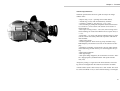
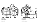
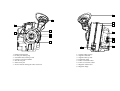
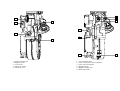
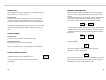
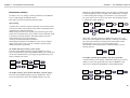
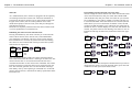
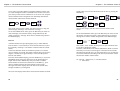
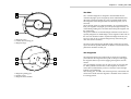
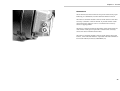
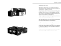
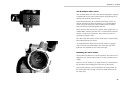
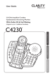
user’s
guide
1
presentation
Chapter 1 - Presentation
Technical Specifications :
Technical specifications and User's guide are subject to change
without notice.
- Super16 only, 172,8° * spinning mirror reflex shutter,
- Around 2 kg (4 Lbs) with on-board battery and film.
- l 245mm, h 140mm, w 110 mm (9.7" x 5.5" x 4.4")
- Time recording by XTRprod compatible AatonCode-II matrixes, accurate to a 1/4 of a frame. The camera can be used as a
master-clock too.
- Fiber-optic viewing screen, 1:1.78 (16/9) ratio viewing screen
shows markings for wide-screen HDTV and 4:3 aspect ratios, G
= x 5.5.
- Frame Rate - 1 to 32 fps with internal Lithium and up to 50 fps
with an external 12V battery TBD and stop-frame with built-in
intervalometer.
- Nikon or PL mount
- Incident lightmeter -dome- showing T-stop and diff. T-stop,
HMI frequency and monitor scan rates on the camera LCD display.
- DistantEye viewfinder “Aaton patent”; the only reflex camera
which doesn't fog the film if the eye is not held against the eyecup.
- Built-in Intervalometer
- Back light display
- 200' quick change magazines, 'B' wound rolls in Aaton's ~flexible~ daylight spools (standard metallic 200 spools and 400'
reels, NO)
"Temporary casting" is engraved on the initial cameras. This housing will be exchanged when the Video Assist becomes available.
* Initial cameras (from # 006 to 025) have a 180° shutter. This shutter will be retrofitted in 172,8° when external housing is exchanged.
5
8
1
2
3
4
5
1 - Magazine release lever
2 - Lightmeter dome
3 - Backlight LCD display
4 - Batteries compartment
5 - LED camera and timecode status indicator
6 - Control panel
7 - Camera run switch
8 - Video assist port
6
7
8
1
2
3
4
5
1 - Viewing screen collimation port
2 - gate rear pressure plate
3 - Film pulldown claw
4 - Take-up sprocket door
5 - Feed sprocket door
6 - Feed sprocket
7 - Take-up sprocket
8 - Magazine locking mechanism
6
7
9
9 - Shutter trigger
10 - Magazine release lever
10
1
1
2
3
6
2
4
7
3
4
5
6
5
7
8
1 - Diopter locking knob
2 - PL lens port locking ring
3 - A-minima fixed viewing screen
4 - camera 172.8°mirror/shutter
5 - Arri PL lens port
6 - Video assist port
7 - Access hole for locking the video assist lens.
1 - Camera rubber eyecup
2 - magazine feed side
3 - magazine take-up side
4- Lightmeter dome
5 - Lemo 5 timecode socket
6 - Lemo 6 accessories socket
7 - Magazine release lever
8 - Magazine hinge.
1
2
5
4
3
1
6
3
6
2
5
1 - Diopter locking knob
2 - Magazine latch
3 - 3/8-16 insert
4 - camera run switch
5 - Video port cover
1 - 3/8-16 mounting hole
2 - Lemo 6 Aaton power base connection
3 - power base locating hole
4 - Magazine hinge
5 - Magazine release lever
6 - Hand strap holder
4
2
control panel
Chapter 2 - The A-Minima Control Panel
A-Minima control panel
The A-Minima control panel consist of an illuminated LCD display,
six buttons to access and adjust all operator functions, and a camera
status LED. Each buttons can have a different function, depending
on the mode you are in.
• Inches the camera by frame when you are in the camera
default display.
• Allows you to select or change the camera parameters within
a menu.
• Allows you to view, access and change the camera
parameters.
• Allows you to enter a selected menu, to change or validate a
parameter within a particular menu.
• Allows you to cancel a parameter or move a step backward
while setting a parameter.
• Wakes up the camera ( if left alone, the camera display will
automaticaly shut off after 5 minutes. Needless to say that
every settings are being kept in the camera internal memory)
• Shows battery voltage.
• Powers down the camera electronics.
• allows you to return to the camera default mode at any time
• exit the "TV SYNC" and INTERVALLOMETER" mode.
Press on it to view the theorical lens aperture.
This LED conveys camera status information.
• Yellow flashing: timecode has been initialized.
• Slow red flashing: low battery.
• Fast red blinking: camera not running at the selected speed
• Solid red: end of film warning
15
Chapter 2 - The A-Minima Control Panel
Chapter 2 - The A-Minima Control Panel
Camera run :
A-minima default display
The running function of the camera motor is accomplished electronically and can be accessed in two ways.
When first powered or after pressing the blue button, the display
shows the camera selected speed / timecode status and remaining
footage.
- If the Aatoncode has not been initialized, the upper line of the display flashes between camera selected speed and “NO TIME”
Press on the "YES" button to remove the NO TIME message.
From the body :
Starting with the camera software version 2.27, the red ON/OFF
switch located on the camera body, above the motor, must be triggered twice (within one second) in order to start the camera motor.
24.000
200 ft
From the Aaton Power Base :
Simply use the Aaton wooden handgrip and connect it to the Lemo2
connector located between the two front rod inserts of the power
base.
and
NO TIME
200 ft
- If the Aatoncode has been initialized in the camera, either from the
A-Minima internal clock or from an external source, the upper line
of the display flashes between the selected speed and the timecode
information.
Camera inching :
24.000
200 ft
From the body :
Use the UP arrow to inch the camera frame by frame.
and
10:00:00
200 ft
Camera running, the display shows the selected speed and the
remaining footage.
From the Power Base :
Use the test position of the wooden handgrip.
24.000
200 ft
Note: the test function of the wooden handgrip is not available for
cameras with a serial number below A100.
Note: If no magazine is installed, the camera will display
"NO MAG" in place of the footage.
Camera software version :
24.000
Press YES and BLUE key simultaneously to see your camera’s
equipment number as well as EPROM version.
For camera software updates, please contact your Aaton
representative.
16
Eq
71
NO MAG
PR V227
If not in use for five minutes, the camera automatically powers itself
down, unless timecode has first been initialized. Press on any keys,
including the run switch, to wake up the camera.
17
Chapter 2 - The A-Minima Control Panel
Chapter 2 - The A-Minima Control Panel
Parameters setting :
In order to view or to change a camera parameter, use the DOWN
key to scroll through the different menus.
Each menu can be accessed in the following order.
Speed setting
A-minima has a selection of preset speed that you can choose from.
You can also make your selection of any 0,001 incremented crystal
speed between 1.000 and 50.000 fps.
When setting the camera to a specific speed, not being part of the
preset ones, A-minima allows you to add or not this particular speed
to the factory selected speed list. The added speed can be later
removed from the preset speed selection.
A factory selected speed cannot be deleted.
The displayed messages can be different if you want to modify a
factory preset speed, or if you want to modify a specific speed,
added to the preset speed menu.
DOWN key, NEW SPEED blinks, press YES then use YES and NO
to select the digit you want to modify, UP or DOWN key to modify
it. After entering the last digit, you can add it to your preset speed
list, press YES to do so or NO if you do not wish to add this specific speed in the preset speed list.
24.000
speed=
preset
preset
200 ft
24.000
new spd
new spd
24.000
speed=
preset
200 ft
24.000
new spd
24.000
25.000
added !
33.333
preset ?
200 ft
Note: when a specific speed is not added to the preset list, a star
shows next to the displayed speed. Simply a warning. Not added or
part of the preset menu, this speed will be erased of the camera
internal memory as soon as you select another speed.
(Nevertheless, when powered down, A-Minima keeps it into its
internal memory)
To modify and select a factory preset speed :
From the camera default display, press the DOWN key once to
access the speed menu, press YES, PRESET blinks, press YES, then
use the UP or DOWN key to go through the speed selection, press
YES to validate your choice.
24.000
add to
33.333
add to
33.260*
preset ?
200ft
To modify a specific speed, added to the preset speed list:
A-minima allows you to modify or delete this speed. If you want to
modify it, access the speed menu, then choose "MODIFY" and
select a new speed from the PRESET or NEW SPEED menu.
25.000
200 ft
To modify a factory preset speed, and choose a specifc speed :
From the camera default display, press the DOWN key once to
access the speed menu, press YES, PRESET blinks, press the
18
33.333
speed=
modify
preset
200 ft
33.333
delete
new spd
33.333
25.000
25.000
200 ft
19
Chapter 2 - The A-Minima Control Panel
Chapter 2 - The A-Minima Control Panel
To delete a specific speed added to the preset list
If you want to deleted it from your preset list, choose DELETE,
then press YES. The camera will default to 1.000 fps.
modify
modify
remove
delete
delete
33.333?
preset
speed=
1.000
removed
1.000
200 ft
ASA setting
Third on the list, the ASA must be adjusted to the exposure index of
the film stock being used. The ISO selector of the camera provides
settings between 25 and 1000 ASA.
Magazine footage setting
Second on the list, press the DOWN key twice, press YES to access
the magazine footage setting. With a fully loaded magazine installed
on the camera press YES again -NEW MAG- to reset the control
panel to count down a full 200ft load.
25.000
mag=
new mag
set @
25.000
0 ft
0 ft
set foot
200 ft
200 ft
If a short end is being used, press the DOWN key -SET FOOT- then
YES. Use the UP or DOWN key to set the counter to the desired
footage, press YES to validate.
new mag
new mag
set foot
set foot
set @
25.000
154 ft
154 ft
200 ft
From the camera default display, press the DOWN key three times
to access the ASA setting menu, press YES, then use the UP or
DOWN key to select the desired ASA. Press YES to validate.
Note: for Aatoncode, proper ASA setting will insure that the timecode matrixes recorded in between the film perforations will be
exposed at an appropriate and useable level. When using the external camera incident lightmeter, it simply insures that the T stop indication shown on the display is the correct one for a particular film
stock. When using the lightmeter, please check the speed setting.
The T stop indication takes the camera speed into account.
24.000
asa =
200 ft
250
set asa
24.000
@ 500
200ft
500
154 ft
Note: a magazine needs to be installed, locked in its running position, for you to have access to the magazine footage setting.
20
21
Chapter 2 - The A-Minima Control Panel
Chapter 2 - The A-Minima Control Panel
Timecode
As a standard feature, the A-minima is equipped with the capability
of recording Aatoncode in camera time. Timecode information is
exposed onto the film by means of seven micro diodes located into
the gate of the camera, near the camera pulldown claw. These
diodes flash rapidly to form the code, as the film pass through the
gate between exposures.
Timecode can be quickly initialized from the camera internal clock
or can be inputted from an external device.
Initializing the camera from its internal clock :
Pressing the DOWN key four times will take you to the timecode
menu of the A-minima. Press YES to enter, CAM TIME blinks,
press YES again. The display will show you the camera internal
time and date for few seconds, the yellow LED will start flashing.
The camera is now initialized and will keep accurate time (within
half a frame) for eight hours.
24.000
timecode
200 ft
24.000
timecode
200 ft
cam time
cam time
new time
new time
year
month
day
01
jul
11
hour
min
validate
23
59
time ?
cam time
new time
09:53:00
24.000
11.feb.01
200ft
Note: The Yellow blinking LED is the garanty that timecode has
been initialized and that the camera is running an accurate time. The
camera internal clock is not accurate and timecode will not be
recorded onto the film if it has not been first initialized. The camera
internal clock does not need the camera to be powered to keep the
time. The timecode generator does. Get into the habit of having a
fresh battery near by when replacing an exhausted one. An internal
camera capacitor allows a full minute for battery replacement before
timecode is lost.
22
Programming the internal clock with a new time :
You can change the camera internal time within the timecode menu.
Access the timecode menu, then press YES. Select NEW TIME
with the DOWN key then press YES. First select the year with the
UP or DOWN key, press YES to validate, A-minima will take you
to each timecode field. After each fields are set as desired (the NO
button allows you to move backward one field at a time) and that
you have reached the minutes, press YES, then press YES again to
validate the time. A-minima displays this new time and date for few
seconds, the yellow LED will start flashing. The camera is now initialized and will keep accurate time (within half a frame) for eight
hours.
23:59:00
24.000
11jul01
200 ft
Note : If the camera has already been initialized and if you need to
change the time, simply access the timecode menu, press YES and
A-Minima will take you to each field at a time.
24.000
timecode
year
200 ft
10:25:00
01
23
Chapter 2 - The A-Minima Control Panel
Initializing the camera with an external device :
The preferred method is by means of the OriginCplus wich inputs
timecode in ASCII form. It is also possible for the camera to receive
information in SMPTE form, directly from a SMPTE device such as
a TC audio recorder.
• Using the OriginCplus :
(please refer to the OC+ manual in order to program it)Make sure
the camera is powered. Connect the OriginCplus to the lemo5 socket located at the rear of the camera, above the lemo6 socket.Press *
on the OriginCplos to send the timecode information. The camera
display will show the timecode and the small yellow LED located to
the right of the display will start to blink.
• Using an external SMPTE device :
Make sure the camera is powered. Connect the cable from the
SMPTE output of the timecode device to the lemo5 receptacle of
the camera. The display will show "LTC IN PROGRESS" then
show the time, the small yellow LED located to the right of the display will start to blink.
Chapter 2 - The A-Minima Control Panel
GMT, another camera or recorder. Go to the "SEND ASCII" display
and press YES to send the timecode information.
The camera will display GOOD 00.0 after the timecode has been
successfully accepted by the device.
If the GMT or audio device is not powered, or if the cable is faulty
the camera will display NO ANSWER.
A-minima can be used to monitor timecode after it has been initialized in another device. Using the lemo5 to lemo5 cable, connect the
camera to the other device. Access the "SEND ASCII" menu then
press YES. The camera will display GOOD, FAIR , BAD, DIF
TIME or BAD DATE , followed by the amount of drift in tenth of a
frame.
The A-minima is comparing the timecode running in this machine to
the one running on its own display.
GOOD
24.000
send
200 ft
ASCII
00.0
send time
reload ?
no answr
Send ASCII ?
A-minima can be use to initialize another ASCII device.
Video SYNC
From the camera default display, access this option by pressing the
DOWN arrow five time (if the timecode has not been initialized,
this option will not show on the camera display)
Connect the camera to the timecode device, using the proper cable.
Most likely, this would be a Lemo5 to Lemo5 cable. Please contact
your Aaton representative or rental house for further information
concerning cables wiring.
The following procedure has to be followed when initializing a
Nagra equipped with a QSIA circuit, or an audio recorder or other
timecode device wich is driven by an Aaton GMT.
When used in conjunction with the small Aaton Power Base, this
option allows you to automatically synchronize the camera to a
source signal such as a computer/video monitor. In that mode, the
UP or DOWN key can phase the camera, programming the relationship between the camera shutter and the source signal. After this one
time adjustment, the phase relationship remains identical every time
the camera is turned on.
The video connector installed on the Aaton power base accepts a
video composite signal.The video sync menu simply allows you to
film a monitor or computer screen with the roll bar set out of view.
With the Lemo5 to Lemo5 cable, connect the A-minima to the
Listed after the camera timecode options, press YES to set the cam-
24
25
Chapter 2 - The A-Minima Control Panel
Chapter 2 - The A-Minima Control Panel
era in video sync mode. Without a magazine installed, run the camera. Look through the camera viewfinder at the monitor screen and
press the up or down arrows until the bar is set out of view. Stop the
camera and then install a magazine. The relationship between the
camera shutter and monitor remains identical.
24.000
video
tv sync*
200 ft
sync
200 ft
Note: If the source signal is faulty, the camera will run at 1fps, the
camera display showing a "NO TV SYNC" message.
To exit the VIDEO SYNC menu, press the BLUE key for three second. The display will show the battery voltage followed by the
"EXIT TV SYNC?" message. Press YES to validate and go back to
the default display.
Interval
already taken. You can reset the frame count to zero by pressing the
DOWN key.
24.000
burst
burst
1 fr
3 fr
interval
interval
3s
7s
7s 200ft
3fb
0
You are now ready to start the camera with the camera on/off
switch.
To exit the INTERVAL menu, press the BLUE key for three second.
The display will show the battery voltage followed by an" EXIT?"
message. Press YES to validate and go back to the default display.
7s
3fr
Nb=0000
A-minima makes time lapse photography easy, it offers different
intervals from 1 to 80 seconds (in one second increment) as well as
the possibility of taking 1 to 99 frames in between intervals (frame
bursts).
In the intervalometer mode, the A-Minima operates at a constant
rate of 2 frames per second. The shutter opening being a fixed 172,8
degrees, it makes for an approximately 1/4 of a second exposure
time for each frames.
From the camera default display, press the DOWN key to access the
INTERVAL menu, then press YES. First set the desired interval
lenght with the UP or DOWN key then press YES to validate.
Set the number of frame burst with the UP or DOWN key , press
YES to validate and enter the intervalometer control screen.
The upper line of the display shows the interval set and the total
footage available in your magazine.
interval
200 ft
> 3s
exit ?
24.000
200ft
Note: With a 172,8° shutter, each exposure is 0,24s instead of 0,25s
if you had a 180 degrees shutter.
In 16mm, a full 200 feet roll contains 8000 frames. When viewed at
24 frames per second, a roll last approx 5 minutes and 30 seconds.
The following formula gives you the actual time T1 i(n seconds) the
event will be filmed in according to the interval, frame burst chosen
and the total number of frame taken.
TI= (interval + frame burst ) x total Nb of frame
2 frame burst
The lower line displays frame burst chosen and the number of frame
26
27
Chapter 2 - The A-Minima Control Panel
Chapter 2 - The A-Minima Control Panel
Display light
In order to save battery power, the A-minima display backlight can
be turned off.
From the camera default display, press the DOWN key eight times
to access the display light menu.
Press YES to enter, select ON or OFF with the UP or DOWN key.
Press YES to validate
24.000
display
on ?
200 ft
light
off ?
Note:When pressing any keys of the control panel, the backlight
will be turned on for 30s, disregarding the display light setting.
Also, to prevent excessive drain on the small on-board lithium batteries,the backlight will automaticaly turn itself off after five minutes. If initialized with timecode, the camera display will flash for
one second every ten seconds.
A-Minima Options:
This is the last menu on the list. It allows you to set the camera
footage units and the camera shutter pulse output.
Counter :
Go to the A-MINIMA OPTIONS menu, then press YES to enter.
COUNTER flashes, press YES then use the UP or DOWN key to
switch the footage counter between feet and meters. Press YES to
validate. The camera will then default to its default display, showing
you the desired footage unit.
24.000
aminima
counter
feet
200 ft
options
shutter
meter
feet
24.000
meter
61 m
28
shutter :
Go to the A-MINIMA OPTIONS menu, then press YES to enter.
COUNTER flashes, press the DOWN key to select SHUTTER,
press YES to access the SHUTTER MODE settings.
Use the UP or DOWN key to scroll through the five different
choices.
Depending on the mode you are in, the camera shutter pulse out
located on pin 5 of the lemo 6 will be different.
24.000
aminima
counter
counter
200 ft
options
shutter
shutter
shutter
mode ?
Normal mode: the camera default mode.
shutter
normal
modify
24.000
mode ?
mode ?
OK
200 ft
Shutter long: When using the intervallometer function of the camera,this mode will synchronize a capping shutter to the camera
frame bursts.
shutter
shutter
modify
24.000
mode ?
long ?
OK
200 ft
Shutter flash: Used to synchronize a flash with the camera shutter.
shutter
shutter
modify
24.000
mode ?
flash ?
OK
200 ft
Camera slave: to slave the camera shutter and speed to another
A-Minima.
shutter
camera
ext syn*
mode ?
slave ?
200 ft
Note: an incoming signal must be present when using the camera in
the "camera slave" mode. If the source signal is faulty, the camera
29
Chapter 2 - The A-Minima Control Panel
Chapter 2 - The A-Minima Control Panel
will run at one frame per second, the red LED flashes and a "NO
EXT SYNC" message is displayed.
Please contact your Aaton representative or rental house for further
information concerning cables wiring.
Camera master: to control another A-Minima speed and shutter.
shutter
camera
modify
24.000
mode ?
master ?
OK
200 ft
30
31
3
magazine
Chapter 3 - Loading the A-Minima
The Film
1
2
2
3
1 - Magazine latch
2 - Camera door locating pin
3 - Magzine hinge
The A-minima magazine is designed to accommodate the new
"Aminima daylight spools" designed by Aaton. Manufactured and
delivered by Eastman Kodak, the spools can handle 200ft of film.
The magazine coaxial design utilizes two identical spools, one on
each side.
The A-minima spools are "daylight friendly". If you load and download your magazine in daylight, you will exposed approximately 5 ft
of film during loading and 2 ft of film when taking the magazine off
the camera body.
The spool is made of two flexible flanges attached on each side of a
specially designed core. Both flanges can be clipped on either side of
the core.You should not need to separate the flanges from the core,
but if you wish to do so, hold one flange firmly while turning the
other one counter-clockwise.
The film is being delivered by Kodak already rolled onto one of the
spool. The film is spooled emulsion out. With its wind clockwise, the
perforation should be towards you.
The magazine
1
1
2
3
1 - Magazine guiding post
2 - Shutter trigger
3 - Magazine serial number
The magazine attach to the camera body by mean of two guiding
post located on the magazine take up side. A third post will trigger
the magazine shutter open when engaging the magazine onto the
camera.
You can manually move this post in order to open or close the shutter. When pushed toward the nose of the magazine, the shutter is
closed. We recommend that you leave it closed to ensure the light
tightness of a loaded mag.
Two locating pins, on either side of the mag throat, will maintain the
camera door closed when the magazine is installed on the camera in
its running position.
35
Chapter 3 - Loading the A-Minima
When engaging the mag onto the camera, the magazine shutter
opens, allowing the two flexible spools to come in contact and be
driven by the camera take-up and feed sprockets. In this position,
both spools are spread apart to ensure a clean and silent passage for
the film.
Loading the magazine
1
2
1 - Feed side
2 - Feed spool
3 - Take-up side
4 - Magazine shutter
3
4
Check that the magazine shutter is in its open position, if not, move
the trigger towards the rear of the magazine to open it.
Open the magazine by pushing on the spring loaded lock and turning
it clockwise. Place the magazine with the take up side to your right..
Release both, feed and take-up spool locking mechanisms by pulling
on the semi-circular lever. Remove the fully loaded spool from the
black bag and peel of the sticker, keeping it attached to the end of the
film as you will need it to attach the film to the take-up spool. Gently
pull approximately one foot of film, being careful not to spread apart
the two flexible flanges. Install the loaded spool onto the mag feed
spindle with its wind clockwise. Press evenly on each side of the
core and, while doing so, push the semi-circular lever down to lock
the spool in place.
Using the sticker, attach the film to the take-up spool. Wind on a few
turn, clockwise and emulsion out. (you should not need to separate
the flanges from the core, but if you wish to do so, hold one flange
firmly while turning the other one counter-clockwise). Place the take
up spool on top of the feed side spool and flip it 180° (the flange previously touching the feed spool should now be facing you). Guiding
the film into the throat of the magazine take-up side, install the spool
on the take-up spindle. Press evenly on each side of the core and,
while doing so, push the semi-circular lever down to lock the spool
in place.
Close the magazine, being careful not to pinch the film, close the
lock and close the magazine shutter.
37
Chapter 3 - Loading the A-Minima
Installing the loaded magazine and threading the A-minima.
Before installing the magazine, adjust the loop length by pulling it to
the beginning of the magazine hinge.
Also, on the camera body, open the feed and take-up sprocket door
by simply pushing them away from the sprockets (fig 1).
Swing the gate pressure plate open by pulling it toward the rear of
the camera.
Before installing the magazine, you should power the camera body.
When powered without a magazine, the camera motor automatically
moves half a turn, in the test position, clearing the claw for the film
to be installed onto the gate.
Install the magazine on the camera body with your right hand, making sure that the two locating pin are engaged into the camera locking mechanisms. While "dropping" the magazine on the camera,
spread apart the film loop at the magazine throat around the outside
of both take-up and feed sprockets.
Engage the film around the upper take up sprocket and close the
sprocket door, making sure that the film's perforations engage the
sprocket teeth.
Engage the film around the lower feed sprocket and close the sprocket door.
Install the film on the camera gate and close the rear pressure plate.
Navigate the film into the gate channel with two fingers on each side
of the pressure plate until you ear this one pop into place. When correctly set, the film should move freely, not being pinched by the
pressure plate. If needed, open the feed sprocket door to adjust the
loop length and center the figure eight loop top and bottom following
the loop marking.
Engage the magazine, pushing it firmly toward the front of the camera. Use the upper arrow located on the control panel to inch the
camera frame by frame. Run the camera a few feet to check your
threading (after you become familiar threading the camera, you
should be able to load the camera without running a few feet of film
to save time and film stock)
39
Chapter 3 - Loading the A-Minima
Pull the magazine locking lever to release the magazine, close the
camera door and re-engage firmly the magazine into position. Press
on the upper arrow to re-engage the claw and set your camera shutter
in the reflex viewing position.
Removing the exposed film spool
After you exposed your full 200 ft roll, you can disengage the magazine from the camera and remove the daylight spool.
Remenber to never pry the spool out of the magazine but to simply
release the spool locking mechanism and flip the magazine up side
down to let the full spool fall into you hand.
Wrap the complete spool in the black bag and into the can to send it
to the lab.
41
4
connectors
Chapter 4 - Connectors
Connectors
The A-minima uses three connectors for power and accessory input
Following is a detailed list, location and main function of each.
The Lemo 6 connector located at the rear of the camera is the main
accessory connection of the A-minima. It provides remote on/off
control and power output as well a s a connection for accessory
such as a capping shutter.
The lemo 6 connector located at the bottom of the camera body provides remote on/off, power input and a connection for accessory
such as the Aaton A-minima Power Base.
The Lemo 5 connector located at the rear of the camera, above the
Lemo 6, is the timecode interface. It provides timecode communication in both ASCII (in and out) and SMPTE (in).
45
5
accessories
Chapter 5 - Accessories
A-Minima Power Base
When used in conjunction with the A-minima camera body, the
Aaton small power base extends the camera functions.without compromising its size, weight. and ease of use.
The power base is multi functional: as a tripod intermediary plate, it
accepts a standard 15mm or 19mm sliding bridgeplate for building
the camera system for studio work. This configuration can accept
Arri, Chrosziel or other manufacturer's mattebox, follow-focus and
support equipment designed for bridgeplate use.
A lighter configuration is also possible using the two 15mm Aaton
screw-in front rods attached to the power base by means of two 3/8"
threaded inserts located at the font of the base.
This configuration can also accept Arri, Chrosziel or other manufacturer's mattebox follow-focus and support equipment
The power base is also an electrical (fused) junction box between a
remote 12 volts power source, the camera body and various accessories such as a zoom control or lens capping shutter.
Using its BNC connector, the power base allows you to automatically synchronize the camera to a source signal such as one delivered
by a computer/video monitor.
Finally a remote ON/OFF capability is offered when connecting an
Aaton wooden handgrip to the power base Lemo 2 socket.
49
Chapter 5 - Accessories
Use the 3/8" screw to attach the Aaton power base to the bottom of
the camera body. A 5mm locating pin insures the correct lateral
positioning of the camera.
- The XLR4 connector located on the operator side is the main 12
volts power input. It is designed to accept a standard XLR4 power
cable. (Do not forget to move the switch, located in the disposable
battery compartment, to the "ext" position).
- The two Lemo 6 connectors located on the opposite side are the
two main accessory connection. Designed to accept a power zoom,
it also carries a sync signal and provides camera on/off
- The Lemo 6 connector located at the top of the power base is the
connection between the A-minima camera body and the power base.
It carries the 12 volt, camera on/off and external sync signals.
Next to it is the main 5 Amp fuse.
- The Lemo 2 connector located between the two front rod inserts
provides camera remote on/off.
The BNC input connector located next to the XLR4 connector is the
connection between the base and a video source signal. When a
valid video signal is present, a small green led, located near the
BNC connector will be lit.
Use a BNC cable connected on one end to the base and on the other
end to the video output of your monitor. On the camera control
panel, press the "down" arrow to access the "video sync" menu.
Press YES to set the camera in video sync mode. Without a magazine installed, run the camera. Look through the camera viewfinder
at the monitor screen and press the up or down arrows until the bar
is set out of view. Stop the camera and then install a magazine. The
relationship between the camera shutter and monitor remains identical.
51
Chapter 5 - Accessories
The A-minima video assist
This on-board flicker less video assist has been designed to integrate
a reliable B & W CCD video camera without compromising the Aminima size, flexibility and ease of use.
Powered internally from the A-minima camera body, it does not
need an outside power cable. Nevertheless, it is recommended to
power it using the Aaton power base installed on the A-minima
body, not from the internal disposable batteries.
The A-minima video assist has two separate video outputs. One is a
standard BNC connector, the other one is a small Fisher4 connector
used for a small mini LCD monitor. This connector carries 12V,
ground and composite video.
The video assist also features a main on/off switch, a small running
LED and manual lens iris control.
As standard from the factory The A-minima camera is equipped
with an internal 75/25 beamsplitter. This means that 25% of the
light from the viewfinder is sent to the CCD target.
Installing the video assist.
You should not usually have to do this operation. The video assist is
designed to stay with the camera body. as it does not add excessive
weight.
However, in some instances, you might need to do it. Please follow
this procedure when installing the video assist on the camera.
Unscrew the video port cover located above the camera motor, on
the control panel side, and pull out the wire bundle used to power
the video assist.
53
Chapter 5 - Accessories
Through the hole located on the upper left corner of the camera lens
port, carefully loosen the tightening screw used to later hold the
video lens onto the camera internal tubular holder.
Do not unscrew it completely as it could fall into the camera housing. two or three turn will suffice.
The video housing is made of two "half shell".
The back one holds the video on/off switch, led and mini monitor
connector, the front one integrates the manual iris and threaded ring
used to secure the video assist onto the camera.
Unscrew the three allen screws holding both part together (see diagram)
Carefully feed the camera wire and its Molex white connector in
between the video lens and video front housing.
Install the video head assembly into the tubular holder located
inside the
camera video port. Note the 45° orientation of the head assembly.
When approaching the video to the camera housing, gently pull on
the camera wire to avoid pinching it.
Push the CCD head all the way in and start turning the video threaded ring clockwise. Slightly rock the video front housing from left to
right in order to engage its locating pin with the cutout machined on
the camera video port. Tighten the locking threaded ring.
Connect the camera wire to the video three pin Molex connector
Connect a BNC cable to a monitor and to the BNC mounted on the
55
Chapter 5 - Accessories
video back housing. Be careful not to pull on the BNC cable as you
could damage the video electrical connections.
Power the A-minima and turn on the video assist.
You should see a picture of the viewing screen on the monitor. Open
the video lens iris by moving its lever towards the rear of the AMinima.
While looking at the image on the monitor gently move the CCD
head assembly until the viewing screen image is in focus and square
to the monitor. When this operation is achieved, hold the unit in
position and access the internal tubular holder screw. Tighten it
moderately.
Replace the video back housing on the video front housing and
secure it in position with the three allen screws, being careful not to
pinch any wires.
57