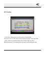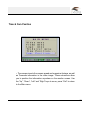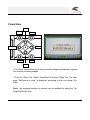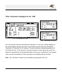
1
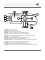
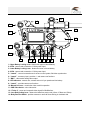
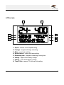
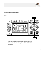
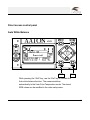
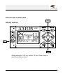
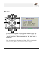
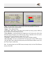
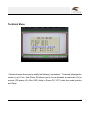
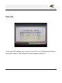
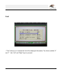
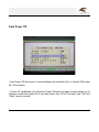
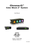
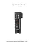
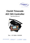
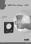
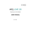
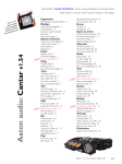
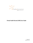
VHR 16 User’s Manual
2007 VHR 1.11
VHR 16 overview
Camera Controls :
LCD Screen
page 3
page 5
Direct access control panel
Video Gain
Color temperature
Auto White Balance
VHR display contrast
VHR display back-light
page 6
page 7
page 8
page 9
page 10
Main menu
page 11
Video menu
Frame
Logo
Technical
Timecode
Font
Auto Power Off
VITC
Time & Cam Position
page 12
page 14
page 16
page 17
page 18
page 19
page 20
page 21
page 22
Frame Store
page 23
Other information displayed on VHR
page 25
2
12 11 10
14
VHR
1
2
3
on
o
f
f
store
9
menu
13
8
shift
exit
4 5 6
7
1 • LED indicator : Power “ON” indicator
2 • Run key : press to turn the power on.
3 • Off key : press both 2 and 3 to turn the power off.
4 • Shift key : access to Color Temperature and White Balance functions.
5 • Down key : scroll through the setup menu and direct access to Gain Control.
6 • Exit key : exit setup menu and access White Balance function (while pressing the shift key).
7 • Manual Iris : control the manual lens iris.
8 • Right key : position video inserted characters and setup inserted frame lines.
9 • “Fisher4” : power and composite video signal for MiniMonitors.
10 • Menu and select Key : access the video setup menu, select functions and to store still frames.
11 • Up key : scroll through the setup menu and direct access to Gain Control.
12 • Store key : access the frame store and image compare function.
13 • Left key : position video inserted characters and setup inserted frame lines.
14 • LCD screen : displays the camera speed and footage, batteries voltage and video parameters.
3
13
14
1
VHR
2
store
12
menu
on
o
f
f
11
shift
exit
3
4
5
6 6
7 7 8 9
10
1 • Upper Battery Locking Lever : fastens the upper on-board battery.
2 • XLR4 : camera and accessories 12 Volts power input.
3 • Lower Battery Locking Lever : fastens the lower on-board battery.
4 • XLR4 : camera and accessories 12 Volts power input.
5 • “Lemo 8” : connect accessories such as lens control system, film/video synchronizer.
6 • “Lemo 6” : accessory input, provides +/- and camera run functions.
7 • “BNC” : video assist analog video output.
8 • LED indicators : camera runs, camera test out of sync speeds and low battery.
9 • “Lemo 2” : provides camera run functions.
10 • Manual Iris Lever : controls the video assist iris operation.
11 • VHR Video Assist : color video assist.
12 • “Fisher 4” : power and composite video signal for MiniMonitors.
13 • Lens Rod Locking Lever : fastens the lateral lens motor rods (19mm, 15,8mm and 15mm).
14 • Body Run/Test Switch : provides camera run and half frame inching on assistant side.
4
LCD screen
1
2
3
6
7
8
4
5
1 • Speed : camera current speed setting.
2 • Footage : magazine footage remaining .
3 • Gain : current gain setting.
4 • White Balance : video color temp setting.
5 • Remaining time : magazine remaining running time.
6 • Voltage : upper XLR4 battery voltage.
7 • Voltage : lower XLR4 battery voltage.
8 • Time & Date : camera TC and user bits setting.
5
Direct access control panel
Gain
Up
VHR
store
menu
shift
exit
on
o
f
f
Down
Press the “Up” and “Down” key to set the video gain to the
desired value. Adjustment range from +9db to -9db in 1db
increments.
6
Direct access control panel
Color Temperature
Up
VHR
store
menu
shift
exit
on
o
f
f
Shift Down
While pressing the “Shift” key, use the “Up” and “Down” keys to
scroll through and set the video color temperature to the
desired value. Three choices: User, 56k and 32k
7
Direct access control panel
Auto White Balance
VHR
store
menu
shift
exit
Shift
Exit
on
o
f
f
While pressing the “Shift” key, use the “Exit” key to activate the
Auto white balance function. The camera switches
automatically to the User Color Temperature mode. The stored
RGB values can be modified in the video setup menu.
8
Direct access control panel
Up
Display contrast
VHR
store
menu
shift
exit
on
Off
o
f
f
Down
While pressing the “Off” key, use the “Up” and “Down” keys to
adjust the display contrast.
9
Direct access control panel
Display backlight
Left
VHR
store
menu
shift
exit
on
Off
o
f
f
Right
While pressing the “Off” key, use the “Left” and “Right” keys to
adjust the display backlight.
10
Main menu
Up
Store
Menu
menu
store
VHR
Right
Left
shift
Shift
exit
exit
Exit
Down
• The main menu is displayed on the monitor when pressing the “Menu” key.
A warning message is displayed on the VHR main screen (see p 26). Use the
“Up” and “Down” keys to select the sub-menus and “Left” and/or “Right” to
access them.
Note : the camera status information is as follows : RUN in red color when
camera is running, STOP in green color when camera is stopped.
11
Video Menu
• Use the Up or Down keys to select the desired parameters . Once selected,
use the “Up” and “Down” keys to modify them, then “Exit” to return to the
previous sub-menu .
• The video menu allows you to set up the following video image parameters :
Gain level, Output (color or Black and White), Color temperature, Color saturation, Color Bar outputing and User color temperature (note that this mode
is only accessible if “user” mode has been chosen in the Color temperature
mode.
12
• Gain : “Up” and “Down” keys to modify the gain value, this parameter can also be
modified using the direct access function.
• Output : Color or Black & White.
• Color temp : USER, 3200 or 5600. Both 3200 and 5600 are factory presets, USER can
be set using the Auto White Balance function.
• Color saturation : a highly saturated color image has a vivid, intense color, while a less
saturated image will appear more muted and grey. With no saturation at all, the hue becomes a shade of grey. Adjustment ranges from 0 to 200%
• Color Bars : generates color bars which can be used to calibrate a monitor.
• User color temp : this menu is activated if the Color temp menu is set to USER. Use the
“Left” and “Right” keys to select the three primary colors Red Green and Blue, use the “Up”
and “Down” keys to modify them.
Note : the values shown are the RGB values previously set by the Auto White Balance
function of the VHR.
13
Frame Menu
• The VHR can insert four different frames in the video image. Each frame can be electronically set in size and position to perfectly match the camera viewing screen markings.
The color and transparency of each frame can be individually set. The area outside the
frame can also be filled with a chosen color and darkened or brightened as desired.
14
From the main menu, use the” Down” key to select the frame sub menu and press the
“Menu” key to enter. You can deactivate the inserted frame by selecting OFF in the line
frame . If you select ON, you have the choice of four different frames labeled frame 1, 2 3
and 4. Each frame will have to be set individually. Use the “Up” and “Down” keys to move
to the line frame color and press the “Menu” key to access the RGB parameters of the
selected frame. Modify the RGB values to have the desired color then press the “Exit” key
to return to the Frame Menu. Use the “Up/Down” keys to select the line “frame top left”
press the “Menu” key to enter and modify the “top and left frame” marking position using
the “Up”, “Down”, “Left” and “Right” keys. Press the “Exit” key to return to the Frame Menu.
Proceed in the same fashion to modify the position of the “bottom and right lines” of the
frame markings.
With no restriction, the inserted frame can be set in size and position to match the viewing
screen layout but It can also be used to outline an object in the picture during a product
shot.
• The line “Frame move” allows you to position the inserted frame in the picture without
affecting its size. To fill the outside area of the frame with a colored shade, move to the
line edge and press the “Left” or “Right” keys to turn the edge On or Off. If set to On, press
“Exit” to return to the Frame Menu and move to the line edge color to modify the RGB
parameters of the frame outside area. Darkening and brightening this area can be done by
modifying the transparency parameter.
15
Logo Menu
• The VHR allows you to insert a Logo in the monitor picture. This Logo can be created and
uploaded in the VHR through a “Lemo 5” - “Serial” port cable.
• From the main menu, use the “Down” key to select the Logo sub menu and press the
“Menu” key to enter. Once the Logo has been generated, you can modify the transparency
(Opacity) and its position on the screen.
• To upload a new Logo, connect your computer to the “Lemo 5” - “Serial” port cable.
Note : please contact Aaton for additional information.
16
Technical Menu
• Technical menu allows you to modify the following” parameters” : Timecode (displayed on
screen or not), Font , Auto Power Off (allows you to choose between an automatic (On) or
manual (Off) power off, of the VHR), delay to Power Off, VITC (video time code) position
and Parity.
17
Time Code
• Time Code Off/On allows you to choose to insert (On) or not (Off) AatonCode information, which consists of Time, Date and Camera equipment number ID.
18
Font
• “Font” allows you to choose the font of the displayed information. Two fonts available “0”
and “1”. Use “Left” and “Right” keys to proceed.
19
Auto Power Off
• Auto Power Off allows you to choose between an automatic (On) or manual (Off) power
off, of the camera.
• “Power off” (modifiable only if the Auto Power Off mode has been chosen) allows you to
choose an automatic power off, of the video assist, from 10 to 60 minutes. Use “Left” and
“Right” keys to proceed.
20
VITC Position
• “Vitc Position” allows you to choose the position of the Vitc lines.
Choice from 10 to 23 in PAL (Aaton recommends line 19), from 13 and 19 in NTSC.
• “Parity” allows you to select the parity of the Vitc lines “Odd” and “Even”.
Make sure that your Post-production tools run properly with the selected value.
21
Time & Cam Position
• The camera inserts the camera speed and magazine footage, as well
as Timecode information in the video image. These sub-menus allow
you to position the information anywhere on the monitor screen. Use
the “Up”, “Down”, “Left” and “Right” keys to move, press “Exit” to return
to the Main menu
22
Frame Store
Up
Store
Menu
menu
store
VHR
Right
Left
shift
Shift
exit
exit
Exit
Down
• The “Store” menu allows you to store one video image and compare it against
the currently incoming images.
• Press the “Store” key. Select “View/Store” and press “Right” key. The message “Shift+store to store” is displayed, proposing to store an image. Proceed.
Note : the message position on screen can be modified by using the “Up/
Down/Right/Left” keys.
23
Stored image.
Once the image has been memorized, you
can compare it to the incoming images. The
memorized image is superimposed and can be
seen with two different types of “view” : “Blend”
or “Checker”.
Press “Menu” key to scroll both views.
Press “Exit” key to leave the Store mode.
“Blend” mode.
Note : the image remains stored only until
another one is stored or, the VHR is powered
off
“Checker” mode.
24
Other information displayed on the VHR
12
ex : “Last shoot” at 12 fps
24
48
ex : “Last shoot” at 24 fps
ex : “Last shoot”at 48 fps
Once the camera has been initialized with Timecode, a “Last shoot” window appears on
the camera display at each shoot stop. This window shows the following information :
Timecode In, Timecode Out, EL (elapse). The shoot duration is always expressed at 24
fps (bottom EL line). If the camera is running at a higher or lower speed, the top EL line
shows the shoot duration at this selected speed. In this case, the bottom EL line automatically converts this duration at 24 fps, giving you the standard projection duration .
Note : the “Last Shoot” window can be recalled by pressing the “Exit” key.
25
Other information displayed on the VHR
When the video menu is generated on screen, the camera display shows the above
information, meaning the video image and its setting modes are accessible through the
connected monitor. Press the “Exit” key to escape.
26
Other information displayed on the VHR
While pressing the “Off” key, a help screen is displayed, showing which parameters can
be modified in combination with this key.
Note : please refer to the Contrast and Backlight menu.
27
Other information displayed on the VHR
While pressing the “Shift” key, a help screen is displayed, showing which parameters can
be modified in combination with this key.
Note : please refer to Direct access control panel menu.
28