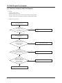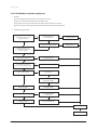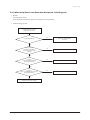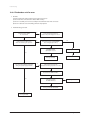
1
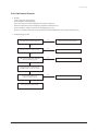
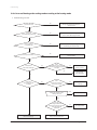
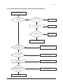
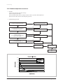
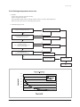
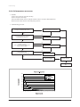
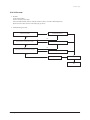
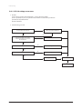
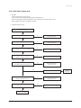
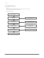
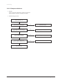
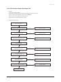
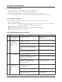
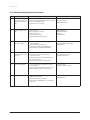
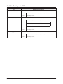
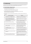
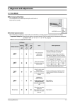
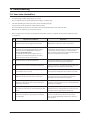
12. Troubleshooting 12-1 Items to be checked first 1. The input voltage should be rating voltage ±10% range. The air conditioner may not operate properly if the voltage is out of this range. 2. Is the link cable linking the indoor unit and the outdoor unit linked properly? The indoor unit and the outdoor unit shall be linked by 5 cables. Check the terminals if the indoor unit and outdoor unit are properly linked by the same number of cables. Otherwise the air conditioner may not operate properly. 3. When a problem occurs due to the contents illustrated in the table below it is a symptom not related to the malfunction of the air conditioner. 12-1 No Operation of air conditioner Explanation 1 The OPERATION indication LED(BLUE) blinks when a power plug of the indoor unit is plugged in for the first time. It indicates power is on. The LED stops blinking if the operation ON/OFF button on the remote control unit is pushed. 2 In a COOL operation mode, the compressor does not operate at a room temperature higher than the setting temperature that the INDOOR FAN should operate. [In case of heat pump model] In a HEAT operation mode, the compressor does not operate at a room temperature lower than the setting temperature that indoor fan should operate. In happens after a delay of 3 minutes when the compressor is reoperated. The same phenomenon occurs when a power is on. As a phenomenon that the compressor is reoperated after a delay of 3 minutes, the indoor fan is adjusted automatically with reference to a temperature of the air blew. 3 Fan speed setting is not allowed in DRY mode. The speed of the indoor fan is set to LL in DRY mode. Fan speed is selected automatically in AUTO mode. 4 Compressor stops operation intermittently in DRY mode. Compressor operation is controlled automatically in DRY mode depending on the room temperature and humidity. 5 Timer LED(ORANGE) of the indoor unit lights up and the air conditioner does not operate. Timer is being activated and the unit is in ready mode. The unit operates normally if the timer operation is cancelled. 6 The compressor stops intermittently in a COOL mode or DRY mode, and fan speed of the indoor unit decreases. The compressor stops intermittently or the fan speed of the indoor unit decreases to prevent inside/outside air frozen depending on the inside/outside air temperature. 7 [In case of heat pump model] Compressor of the outdoor unit is operating although it is turned off in a HEAT mode. When the unit is turned off while de-ice is activated, the compressor continues operation for up to 9 minutes(maximum) until the deice is completed. 8 [In case of heat pump model] The compressor and indoor fan stop intermittently in HEAT mode. The compressor and indoor fan stop intermittently if room temperature exceeds a setting temperature in order to protect the compressor from overheated air in a HEAT mode. 9 [In case of heat pump model] Indoor fan and outdoor fan stop operation intermittently in a HEAT mode. The compressor operates in a reverse cycle to remove exterior ice in a HEAT mode, and indoor fan and outdoor fan do not operate intermittently for within 20% of the total heater operation Samsung Electronics 12-2 Fault Diagnosis by Symptom 12-2-1 No Power (completely dead)-Initial diagnosis 1. Checklist : 1) Is input voltage normal? 2) Is AC power linked correctly? 3) Is input voltage of DC regulator IC KA7805 (IC02) normal? (11VDC-12.5VDC) 4) Is output voltage of DC regulator IC KA7805 (IC02) normal? (4.5VDC-5.5VDC) 2. Troubleshooting procedure Unplug the power cord and plug it after 30 seconds Press the Power Button on the remote control unit to operate the air conditioner operate Check the display board does not operate Check the indoor unit control board Yes Check whether 2 wires of power cord are connected correctly to the terminal block and control board. No Reconnect wires correctly Yes Check whether the fuse on the control board is normal. FUSE(F701) : T3.15[A]/250[V] No Replace fuse Yes Check the output of SMPS on the control board. Input power: AC230±15%[V] IC02 Input: DC12[V] IC02 output: DC5[V] No PCB should be replaced Yes Check the setting temperature Samsung Electronics 12-2 Troubleshooting 12-2-2 The Outdoor unit power supply error 1. Checklist : 1) Are the input power voltage and the power connection correct? 2) Is there no Fuse short in the indoor unit and outdoor unit? 3) Is the cable connected correctly between the indoor unit and outdoor unit in order. 4) Is the wire connected correctly to the terminal block of the indoor unit and outdoor unit? 2. Troubleshooting procedure Is the voltage of indoor unit terminal block 1 and 2 correct after power input? No Is the R701 resistance of indoor PCB 200Ω? Yes Is the indoor unit fuse normal? No No Exchange the PCB. Exchange the fuse. Pull out the power cord and execute the following step after 30 seconds. Is the outdoor unit normal? No Exchange the fuse. Yes Is the outdoor unit normal? Is the reactor connected correctly? No Connect the reactor wire. Yes Is the +, - of C102 short? No Disassemble the PCB from the case. Yes Is there no error at the insertion of PCB? Yes Yes Exchange the PCB. Exchange the PCB. Yes Is the +,- of C102 short? Yes Exchange the PCB. No Are the BLDC FAN Wire 1 and 3 short? Yes Exchange the BLDC FAN. Normal Operation Exit 12-3 Samsung Electronics Troubleshooting 12-2-3 When the Up/Down Louver Motor Does Not Operate. (Initial Diagnosis) 1. Checklist : 1) Is input voltage normal? 2) Is the Up/Down louver motor properly connected with the connector (CN61)? 2. Troubleshooting procedure Unplug the power cord and plug it after 30 seconds Is STD lamp blinking? No Check as in the procedure No Power. Yes Does operation start when swing button of the remote control unit pushed? Yes Normal No Voltage at pin #30~#34 of micom (IC04) change?(Squarewave) No Micom (IC04) is faulty. Yes Voltage at pin #2 ~ #5 of CN61(motor connector) change?(Squarewave) No Driver IC05/06 (ULN2003A) is faulty. Yes Up/Down louver motor is faulty. Samsung Electronics 12-4 Troubleshooting 12-2-4 The Outdoor unit Fan error 1. Checklist : 1) Are the input power voltage and the power connection correct? 2) Is the motor wire connected to the outdoor PCB correctly? 3) Is there no assembly error or none-assembly in the terminal of motor wire connector? 4) Is there no obstacle at the surrounding of motor and propeller? 2. Troubleshooting procedure Is the Pin voltage of CN01 #1, #3 over 250V? No Follow the Check Procedure of outdoor unit power supply error check. No Does the Pin voltage of IC01(MICOM) No.13 change?(Square-Wave) Yes Is the Pin voltage of CN01 #3, #5 within 1V~5V during the operation? No Yes FAN DRIVE CIRCUIT (Q901,Q902 etc.) error Exchange the PCB. Yes MICOM Error Exchange the PCB. Is the Pin voltage of CN01 #6 changed during the operation?(Square-Wave) No Pull out the power cord and execute the following step after 30 seconds. Disassemble the BLDC FAN Wire. Yes Is the short between the BLDC FAN Wires? No Exchange the PCB. Yes Exchange the BLDC FAN MOTOR. Exchange the PCB. 12-5 Samsung Electronics Troubleshooting 12-2-5 Total current Trip error 1. Checklist : 1) Is the input power voltage proper? 2) Is the refrigerant charged properly? 3) Does the compressor rotate normally? (Reverse rotation, Locking etc.) 4) Dose the outdoor fan operate normally? (Fan propeller loss, Motor error etc.) 5) Is the installation condition of outdoor unit good? (Piping, Space etc.) 6) Is there no ventilation obstruction at the surrounding of outdoor? (Outdoor unit cover, Fan front obstruction etc.) 2. Troubleshooting procedure Is the installation of outdoor unit good? No Reinstall and remove the obstruction. Yes Dose the compressor rotate normally? No Exchange the compressor. Yes Is the assembly of R418, R413, IC41, C437 and the peripheral part good? No Exchange the PCB. Yes Pull out the power cord and exchange the PCB from the case after 30 seconds. Is the assembly of Micom and peripheral circuit part good? No Exchange the PCB. Yes Check again after assembly of PCB. Samsung Electronics 12-6 Troubleshooting 12-2-6 In case of heating at the cooling mode or cooling at the heating mode 1. Troubleshooting procedure Is the Thermo off? Yes Change the setting temperature of remote control. Yes Operate it with a heating mode as soon as the defrosting is finished. Yes After 3 minutes, cooling and heating start automatically. No Is the unit in the defrosting operation? No Is the compressor in 3 minutes off? No No Indoor operation SW is on. Turn the SW On. Yes Is much frost in the heat exchanger? Yes Is the outdoor air sensor and outdoor heat exchanger attached correctly? No Yes Over shortage of the refrigerant No Does the 4 way valve operate normally? No Is the 4 way valve connector connected correctly? Attach the sensor correctly. No Connect the connecter correctly. Yes Check the resistance value of 4 way valve coil. NG 4-WAY valve coil error OK Dose the voltage of AC 220V apply to the connector of 4 way valve coil during the operation? No Exchange the outdoor PCB. Yes Go to the next page 12-7 4 way valve main body error Samsung Electronics Troubleshooting In case of heating at the cooling mode or cooling at the heating mode(cont.) From the previous page Does the EEV operate normally? No No Is much frost in the heat exchanger? Connect the connector. Yes Check the resistance value of EEV coil. NG EEV coil error OK Yes Is much frost in the heat exchanger? No Exchange the out PCB. Yes EEV main body error Does the outdoor fan operate at the operation of compressor? Yes The over shortage of refrigerant, Insufficient Capacity, Load estimation error No Is the outdoor fan connected correctly? No Connect the connector. Yes Check the resistance value of outdoor fan. NG Outdoor fan error OK Dose the voltage of DC300V apply to the connector of outdoor fan during the operation of outdoor unit? Yes Check the motor wire. No Outdoor PCB error Samsung Electronics 12-8 Troubleshooting 12-2-7 Outdoor temperature sensor error 1. Checklist : 1) Is the sensor connector connected correctly? 2) Is the sensor placed correctly? 3) Does the both terminal of sensor satisfy the resistance value in accordance with temperature? 4) Is the resistance value of sensor connection pull_up correct? 2. Troubleshooting procedure Is the sensor connector connected correctly in accordance with a color? Reconnect the sensor connector. Yes No Is the temperature sensor connected correctly without separation? Change the position of sensor. Yes No Does the both terminal of sensor satisfy the resistance value in accordance with temperature? (Refer to the R/T TABLE) No Exchange the sensor. Yes No Is the resistance value of sensor connection pull_up 18.2K? No Exchange the PCB. Yes Exchange the PCB. Normal operation Exit 400.0 350.0 300.0 250.0 200.0 150.0 100.0 50.0 12-9 94 103 85 76 67 58 49 40 31 22 13 4 -5 -14 -23 -32 -41 -50 0.0 Samsung Electronics Troubleshooting 12-2-8 Discharge temperature sensor error 1. Checklist : 1) Is the sensor connector connected correctly? 2) Is the sensor placed correctly? 3) Does the both terminal of sensor satisfy the resistance value in accordance with temperature? 4) Is the resistance value of sensor connection pull_up correct? 2. Troubleshooting procedure Is the sensor connector connected correctly in accordance with a color? Reconnect the sensor connector. Yes No Is the temperature sensor connected correctly without separation? Change the position of sensor. Yes No Does the both terminal of sensor satisfy the resistance value in accordance with temperature? (Refer to the R/T TABLE) No Exchange the sensor. Yes No Is the resistance value of sensor connection pull_up 24K? No Exchange the PCB. Yes Exchange the PCB. Normal operation Exit 600.0 500.0 400.0 300.0 200.0 100.0 Samsung Electronics 160 152 144 136 128 120 112 96 104 88 80 72 64 56 48 40 32 24 8 16 0 0.0 12-10 Troubleshooting 12-2-9 Coil temperature sensor error 1. Checklist : 1) Is the sensor connector connected correctly? 2) Is the sensor placed correctly? 3) Does the both terminal of sensor satisfy the resistance value in accordance with temperature? 4) Is the resistance value of sensor connection pull_up correct? 2. Troubleshooting procedure Is the sensor connector connected correctly in accordance with a color? Reconnect the sensor connector. Yes No Is the temperature sensor connected correctly without separation? Change the position of sensor. Yes No Does the both terminal of sensor satisfy the resistance value in accordance with temperature? (Refer to the R/T TABLE) No Exchange the sensor. Yes No Is the resistance value of sensor connection pull_up 18.2K? No Exchange the PCB. Yes Exchange the PCB. Normal operation Exit 400.0 350.0 300.0 250.0 200.0 150.0 100.0 50.0 12-11 103 94 85 76 67 58 49 40 31 22 13 4 -5 -14 -23 -32 -41 -50 0.0 Samsung Electronics Troubleshooting 12-2-10 Fan error 1. Checklist : 1) Isn’t the fan locked? 2) Is the sensor placed correctly? 3) Does the both terminal of sensor satisfy the resistance value in accordance with temperature? 4) Is the resistance value of sensor connection pull_up correct? 2. Troubleshooting procedure Remove the Fan lock. Isn't the Fan locked? Yes Is the connector connected correctly? No No Connect the connector. Yes No Is the color of Fan wire matched correctly? No Exchange the Fan. Yes Exchange the PCB. Normal operation Exit Samsung Electronics 12-12 Troubleshooting 12-2-11 DC-Link voltage sensor error 1. Checklist : 1) Is the voltage of indoor unit terminal block 1, 2 correct after power supply? 2) Is the capacitor(C101, C102, C103) for DC-Link assembled in accordance the specification? 3) Are R112, R113, R114 470 Kohm? 4) Is R115 14.3Kohm? 2. Troubleshooting procedure Apply the troubleshooting for outdoor unit power supply error. Is the voltage of indoor unit terminal block 1, 2 correct after power supply? Yes Is the capacitor(C101, C102, C103) for DC-Link assembled in accordance the specification? No No Connect the connector. Yes Are R113, R114, R115 470kohm? No Exchange the PCB. Yes Is R116 14.3kohm? No Exchange the Fan. Yes Exchange the PCB. Normal operation Exit 12-13 Samsung Electronics Troubleshooting 12-2-12 O.C.(Over Current) error 1. Checklist : 1) Is the Shunt resistance value correct? 2) Is the condition of surrounding temperature abnormal overload? 3) Is there any problem as like the temperature sensor separation or measurement value error? 4) Is the interphase resistance of compressor normal? 2. Troubleshooting procedure Restart after power off. No Is the O.C.(Over Current) error occurred? Terminate the service. Yes No Is the Shunt resistance value normal? Exchange the PCB. Yes No Is the interphase resistance value of compressor (uv, vw, wu) normal? Exchange the Compressor. Yes No Is the compressor body and interphase resistance insulated? Exchange the Compressor. Yes No Is the condition of indoor/outdoor temperature normal load? Restart after returning to the normal load. Yes Yes Is the position of temperature sensor and the sensing value normal? Is the O.C. error occurred again? No No Terminate the service. Correct the sensor position or exchange the sensor. Yes Is the connection cable for the compressor and power terminal normal? No Correct the cable connection. Yes Exchange the PCB. Samsung Electronics 12-14 Troubleshooting 12-2-13 Communication error 1. Checklist : 1) Is the communication cable between the indoor unit and outdoor unit connected correctly? 2) Isn’t the power cable and communication cable error? 2. Troubleshooting procedure Restart after power off. Is the communication error occurred again? No Terminate the service. Yes Isn't the power cable and communication cable error? No Correct the wrong wiring. Yes Is the connection of communication cable normal? No Correct the connection of communication cable. Yes Is it the outdoor 2 Micom(Inverter + Main) model? No Exchange the indoor/outdoor unit PCB. Yes Exchange the outdoor unit PCB. 12-15 Samsung Electronics Troubleshooting 12-2-14 Compressor start error 1. Checklist : 1) Is the connection of cable for the compressor and power? 2) Is the interphase resistance of compressor normal? 2. Troubleshooting procedure Restart after power off. Is the restart error occurred again? No Terminate the service. Yes Is the interphase resistance value of compressor (uv, vw, wu) normal? No Exchange the compressor. Yes Is the compressor body and interphase resistance insulated? No Exchange the compressor. Yes Is the connection cable for the compressor and power terminal normal? No Correct the cable connection. Yes Exchange the PCB. Samsung Electronics 12-16 Troubleshooting 12-2-15 Compressor lock error 1. Checklist : 1) Is the connection of cable for the compressor and power? 2) Is the interphase resistance of compressor normal? 2. Troubleshooting procedure Restart after power off. Is the lock error occurred again? No Terminate the service. Yes Is the interphase resistance value of compressor (uv, vw, wu) normal? No Exchange the compressor. Yes Is the compressor body and interphase resistance insulated? No Exchange the compressor. Yes Is the connection cable for the compressor and power terminal normal? No Correct the cable connection. Yes Exchange the PCB. 12-17 Samsung Electronics Troubleshooting 12-2-16 DC Link Over voltage/ Low voltage error 1. Checklist : 1) Is the power voltage normal? 2) Is the voltage of front and back terminal of indoor(outdoor) power relay normal? 3) Is the resistance value for DC Link voltage detection NORMAL? 4) Is the resistance value of DC Link discharge normal? 5) Is the appearance of DC Link Capacitor normal? 2. Troubleshooting procedure Restart after power off. Is the DC Link voltage error occurred again? No Terminate the service. Yes Is the power voltage normal? No Terminate the service. Yes Is the front and back terminal voltage of indoor/outdoor power relay normal? No Exchange the PCB. Yes Reassembly the PCB. Yes Is the appearance of DC Link Capacitor normal? No Exchange the PCB. Yes Is the resistance for the detection of DC Link voltage normal? No Exchange the PCB. Yes Is the resistance value of DC Link discharge normal? No Exchange the PCB. Yes Is the reactor insulation damaged? No Exchange the PCB. Yes Exchange the reactor. Samsung Electronics 12-18 Troubleshooting 12-2-17 When the remote control is not receiving 1. Check if the connector was normally assembled. 2. Put the set in operation and check the voltage of No. 15(+) and No. 16(-) of the main PCB CN91 while operating the remote control. When the voltage descends below 3V, the assembly module PCB is normal and the main PCB is poor. Then replace the main PCB. 3. Replace the assembly display PCB because the module PCB is poor if the voltage between No. 15~16 of CN91 maintains 5V after the remote control starts operation. 12-2-18 The others 1. AC Line Zero Cross Signal OUT – Check the assembly condition of peripheral part of IC21, ZD21, ZD20 and D200 on the PCB. 2. Capacity miss match – Check again the indoor unit option code. 12-19 Samsung Electronics 12-3 PCB Inspection Method 12-3-1 Pre-inspection Notices 1. Check if you pulled out the AC power plug when you eliminate the PCB or front panel. 2. Don’t hold the PCB side not impose excessive force on it to eliminate the PCB. 3. Don’t pull the lead wire but hold the whole housing to connect or disconnect a connector to the PCB. 4. In case of outdoor PCB disassembly, check first the complete discharge of condenser (C103) after 30 seconds power off. 12-3-2 Inspection Procedure 1. Check connector connection and peeling of PCB or bronze coating pattern when you think the PCB is broken. 2. The PCB is composed of the 3 parts. 1. Indoor Main PCB Part : MICOM and surrounding circuit, relay, room fan motor driving circuit and control circuit, sensor driving circuit, power circuit of DC12V and DC5V, and buzzer driving circuit. 1. Display part : LED lamp, Switch, Remocon module 1. Outdoor Main PCB part : MICOM and surrounding circuit. IPM and PFC circuit and control circuit. 1. EMI PCB Part : Line filter and Noise Capacitor, Varistor 12-3-3 Indoor Detailed Inspection Procedure No Procedure 1 Plug out and pull the PCB out of the electronic box. Check the PCB fuse. 1) Is the fuse disconnected? 2 Supply power. If the operating lamp twinkles at this time, the above 1)~3) have no relation. Checking the power voltage. 3 4 Press the ON/OFF button. Press the ON/OFF button. 1. FAN Speed [High] 2. Continuous Operation Samsung Electronics Inspection Method 1) Is the DB71 input voltage AC200V~AC240V? Cause • Over current • Indoor Fan Motor Short • AC Part Pattern Short of the MAIN PCB • Power Cord is fault, Fuse open. Wrong Power Cable Wiring, AC Part is faulty. 2) Is the voltage between both terminals of the C104 on the 2nd side of the transformer DC12V ±0.5V? • Switching Trans or Power Circuit is faulty 3) Is the voltage between both terminals of OUT and GND of IC19(KA78L05) DC5V ±0.5V? • Power Circuit is faulty, Load Short Checking the power voltage. 1) Is the voltage over AC180V being imposed on 1) terminal #3 and #5 of the fan motor connector(CN72)? • Relay(RY71) Coil Disconnection, IC05 is faulty 2) Check the voltage of both terminals of terminal block 1 and N(1) after 3 minute operation.: AC220V • Relay(RY71) Contact is faulty 1) Is the voltage over AC180V being imposed on 1) terminal #3 and #5 of the fan motor connector(CN72)? • Fan Motor of the indoor is faulty 2) The fan motor of the indoor unit doesn’t run. • Fan Motor Connector(CN72) is faulty 3) The power voltage between terminal #3 and #5 of the connector(CN72) is 0V. • ASS’Y Main PCB is faulty • Connection is faulty 12-20 Troubleshooting 12-3-4 Outdoor Detailed Inspection Procedure No Procedure Inspection Method 1 Wait 30 seconds over after disconnecting the power cable Check the outdoor PCB. 1) Is C101 discharged? 2) Is the resistance of both terminals of C101 opened? 3) Is the fuse of EMI PCB normal? 4) Is the reactor wire connected? • Over Current • Inner short of PCB • BLDC FAN Motor Error 2 Check the Outdoor unit PCB. 1) Is R701 200ohm? 2) Does ry74 operate normally? (IC05 & 16:0V, 1:5V) 3) Is the fuse(F701) normal? 4) Is the Sub PCB assembled normally? • Outdoor PCB Error • SUB Relay(RY74) Error • IC05 Error • Indoor PCB Error 3 Check the LED lighting after power supply. 1) Normal: Red: Light On, Green: Flickering, Yellow: Light Off? 2) Is the voltage of C101 250V over? 3) Is the input of IC19 8V, and the output 5V? 4) Recheck after disassembling BLDC FAN Wire. • Inner short of outdoor PCB • Wrong assembly of outdoor PCB • BLDC FAN Error 4 Check the condition of 1) Is the green LED light on once per second? indoor & outdoor connec- 2) Is the indoor & outdoor connection able tion cable. connected in order? 3) Is the grounding wire connected to the both of indoor & outdoor unit? 4) Is the voltage of terminal block N(1), 225V? • Wrong connection of Indoor/Outdoor wiring • Wrong assembly of outdoor 5 Check the Comp Wire. 1) Is it connected red, blue, and yellow in order in counterclockwise. 2) Are the valve and its installation condition good? 3) Is the installation condition of outdoor unit? • Wrong assembly • Installation condition is bad. 6 Check the BLDC Fan. 1) Is CN01 1, 3 over 250V? 2) Is CN01 3, 5 within 1V~5V? 3) Is the voltage of CN01 6 changed? 4) Is the resistance of BLDC Motor 1, 3 opened after power off? • Outdoor PCB Error • BLDC Motor Error 12-21 Cause communication circuit Samsung Electronics 12-4 Main Part Inspection Method Part Room Temperature Sensor Room Fan Motor Breakdown Inspection Method Measure resistance with a tester Normal At the normal temperature 37kΩ~ 8.3kΩ(-7˚C~+30˚C) *Refer to Table 12-3-4. Abnormal ∞, 0Ω . . . Open or Short Measure the resistance between terminals of the connector (CN72) with a tester. Normal Abnormal Stepping Motor Samsung Electronics At the normal temperature (10˚C ~ 30˚C) Compare terminal Resistance Remark Yellow, Blue 404.4Ω ± 10% Main Yellow, Red 340Ω ± 10% Sub ∞, 0Ω . . . Open or Short Measure the resistance between the red wire and each terminal wire with a tester. Normal About 300Ω at the normal temperature (20˚C ~ 30˚C) Abnormal ∞, 0Ω . . . Open or Short 12-22