1
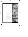
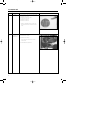
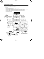
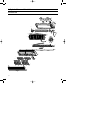
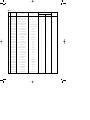
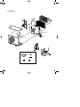
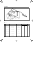
cover
5/14/01 8:23 PM
Page 1
ROOM AIR CONDITIONER
INDOOR UNIT
OUTDOOR UNIT
AQ24A2QC
AQ18A2QC
UQ24A2QC
UQ18A2QC
SERVICE
Manual
AIR CONDITIONER
CONTENTS
1. Installation
2. Disassembly and Reassembly
3. Troubleshooting
4. Exploded Views and Parts List
5. Refrigerating Cycle Block Diagrams
6. Wiring Diagrams
7. Schematic Diagrams
E DB68-00276A(5)
5/14/01 8:24 PM
Page 1
1. Installation
1-1 Refrigerant Refill Procedure
• Refill an air-conditioner with refrigerant when refrigerant has been leaked at installing or using
1. Purge air(for new installation only).
2. Turn the 3-way valve clockwise to close,
connect the pressure gauge(low
pressure side) to the service valve, and
open the 3-way valve again.
Suspension hook
3. Connect the tank to refill with Refrigerant
High
pressure
gauge
Compound
gauge
Hand
wheel
Finger tight
fittings
4. Set the unit to cool operation mode.
For mounting
other and of
hose when
not in use
5. Check the pressure indicated by the pressure gauge(low
pressure side).
* Standard pressure is should be 4.5~5.5kg/cm2 in a
reqular, high operation mode.
6. Open the refrigerant tank and fill with refrigerant until
the rated pressure is reached.
* It is recommended not to pour the refrigerant in too
quickly, but gradually while operating a pressure valve.
Connected to
high pressure
side
Charging
line
R-22
new1-
7. Stop operation of the air conditioner.
8. Close the 3-way valve, disconnect the pressure gauge,
and open the 3-way valve again.
9. Close the cap of each valve.
1
new1-
5/14/01 8:24 PM
Page 2
1-2 “Pump down” Procedure
•
Pump down' shall be carried out when an evaporator is replaced or when the unit is relocated in
another area.
1. Remove the caps from the 2-way valve and the
3-way valve.
2. Turn the 3-way valve clockwise to close and
connect a pressure gauge(low pressure side) to
the service valve, and open the 3-way valve again.
2-Way Valve
3. Set the unit to cool operation mode.
(Check if the compressor is operating.)
4. Turn the 2-way valve clockwise to close.
3-Way Valve
5. When the pressure gauge indicates "0" turn the
3-way valve clockwise to close.
6. Stop operation of the air conditioner.
7. Close the cap of each valve.
Relocation of the air conditioner
• Refer to this procedure when the unit is
relocated.
1. Carry out the pump down procedure (refer
to the details of 'pump down').
2. Remove the power cable.
3. Disconnect the assembly cable from the
indoor and outdoor units.
4. Remove the flare nut connecting the indoor
unit and the pipe.
At this time, cover the pipe of the indoor
unit and the other pipe using a cap or vinyl
plug to avoid foreign material entering.
2
5. Disconnect the pipe connected to the outdoor unit.
At this time, cover the valve of the outdoor
unit and the other pipe using a cap or vinyl
plug to avoid foreign material entering.
6. Make sure you do not bend the connection
pipes in the middle and store together with
the cables.
7. Move the indoor and outdoor units to a new
locatioon.
8. Remove the mounting plate for the indoor
unit and move it to a new location.
new1-
5/14/01 8:25 PM
Page 3
2. Disassembly and Reassembly
Stop operation of the air conditioner and remove the power cable before repairing the unit.
2-1 Indoor Unit
No
Parts
1
Front Grille
Procedure
Remark
1) Stop the air conditioner operation and block
the main power.
2) Seperate tape of front panel upper.
3) Contract the second finger to the left, and
right handle and pull to open the inlet grille.
4) Take the left and right filter out.
* Take the Deadorizing and Electrostatic filter out.
(ONLY “1” and “5” Series models)
5) Loosen one of the right fixing screw and
seperate the terminal cover.
6) Loosen two fixing screws of front grille.
7) Pull the upper left and right of discharge softly for the outside cover to be pulled out.
8) Pull softly the lower part of discharge and
push it up.
Caution;
Assemble the front panel and fix the
hooks of left and right.
3
new1-
5/14/01 8:25 PM
Page 4
No
Parts
Procedure
2
Ass’y Tray Drain.
1) Do “1”, above.
Separate the drain hose from the extension drain
hose.
2) Take the display PCB out.
(Center of indoor unit)
3) Loosen two fixing screws of left and right
4) Pull tray drain out from the back body.
3
Electrical Parts
(Main PCB)
1) Do “1”, “2”, above
2) Take all the connector of PCB upper side out.
(Inclusion Power cord)
3) Separate the outdoor unit connection wire from
the terminal block.
4) If pulling the Main PCB up. it will be taken out.
(Separate the TRANS hook. it before).
4
Heat Exchanger
1) Do “1” and “2”, “3”, above
2) Loosen two fixing earth screws of right side.
3) Separate the connection pipe.
4) Separate the bush body at the upper side and
holder at the rearside.
5) Loosen the two fixing screws of left side.
6) Lifting the heat exchanger up a little to push the
up side for separation from the indoor unit.
4
Remark
new1-
5/14/01 8:25 PM
Page 5
No
Parts
3
Fan Motor and
Cross Fan
Procedure
Remark
1) Do “1” “2” ”3” “4”, above.
2) Loosen the fixing three screws and separate
the motor holder.
3) Loosen the fixing screw of fan motor.
(By use of M3 wrench)
4) Separate the fan motor from the fan.
5) Separate the fan from the left holder bearing.
5
new1-
5/14/01 8:25 PM
Page 6
2-2 Outdoor Unit
No
Parts
1
Cabinet
Procedure
1)
2)
3)
4)
5)
6)
Turn off the unit and remove the power cable
Remove the top cover.
Remove the control box cover.
Unplug the ass'y cable.
Remove the cabi-side.
Remove the cabi-front.
* When you assemble the parts, check if the
each parts and electric connectors are fixed
firmly.
2
Fan Motor &
Propeller Fan
1) Do Procedure 1 above.
2) Remove the nut flange.
(Turn to the right to remove as it is a left
turned screw)
3) Disassemble the propeller fan.
6
Remark
new1-
5/14/01 8:25 PM
Page 7
3. Troubleshooting
3-1 Items to be checked first
1) Is the voltage of the power correct?
The input voltage shall be the rating voltage ±10%.
The airconditioner may not operate properly if the voltage is out of this range.
2) Is the link cable linking the indoor unit and the outdoor unit linked properly?
The indoor unit and the outdoor unit shall be linked by 6 cables.
Check the terminals if the indoor unit and outdoor unit are properly linked by the same number of
cables.
Otherwise the airconditioner may not operate properly.
3) When a problem occurs due to the contents illustrated in the table below it is a symptom not
related to the malfunction of the airconditioner.
Explanation
NO
Operation of air conditioner
1
3
The COOL operation indication LED (Green) blinks when a
power plug of the indoor unit is plugged in for the first time.
In a COOL operation mode, the compressor does not operate
at a room temperature higher than the setting temperature
that the INDOOR FAN should operate.
In a HEAT operation mode, the compressor does not operate
at a room temperature lower than the setting temperature
that indoor fan should operate.
Fan speed setting is not allowed in AUTO or DRY mode.
4
Compressor stops operation intermittently in DRY mode.
5
Compressor of the outdoor unit is operating although it is
turned off in a HEAT mode.
6
Timer LED only of the indoor unit lights up and the
air conditioner does not operate.
The compressor and indoor fan stop intermittently in HEAT
mode.
2
7
8
Indoor fan and outdoor fan stop operation intermittently in
a HEAT mode.
9
The compressor stops intermittently in a COOL mode or DRY
mode, and fan speed of the indoor unit decreases.
It indicates power is on. The LED stops blinking if the operation
ON/OFF button on the remote control unit is pushed.
In happens after a delay of 3 minutes when the compressor is
reoperated. The same phenomenon occurs when a power is on.
As a phenomenon that the compressor is reoperated after a delay
of 3 minutes, the indoor fan is adjusted automatically with
reference to a temperature of the air blew
The speed of the indoor fan is set to LL in DRY mode.
Fan speed is 5 steps is selected automatically in AUTO mode.
Compressor operation is controlled automatically in DRY mode
depending on the room temperature and humidity.
When the unit is turned off while de-ice is activated, the
compressor continues operation for up to 9 minutes (maximum)
until the deice is completed.
Timer is being activated and the unit is in ready mode.
The unit operates normally if the timer operation is cancelled.
The compressor and indoor fan stop intermittently if room
temperature exceeds a setting temperature in order to protect the
compressor from overheated air in a HEAT mode.
The compressor operates in a reverse cycle to remove exterior ice
in a HEAT mode, and indoor fan and outdoor fan do not operate
intermittently for within 20% of the total heater operation
The compressor stops intermittently or the fan speed of the indoor
unit decreases to prevent inside/outside air frozen depending on
the inside/outside air temperature.
4) Indoor unit observes operation condition of the air conditioner, and displays self diagnosis details
on the display panel.
NO
Display
Self Diagnosis
1
Operating LED blinking (1Hz)
Restore from power failure (input initial power)
2
TIMER LED blinking (1Hz)
Indoor unit Room sensor Error (open or short)
3
OPERATING and TIMER LED blinking (1Hz)
Indoor unit heat exchanger temperature sensor Error (open or short)
4
FAN LED blinking (1Hz)
Indoor fan malfunctioning (for spead is Below 38Orpm)
7
new1-
5/14/01 8:25 PM
Page 8
3-2 Fault Diagnosis by Symptom
3-2-1 No Power(completely dead)-Initial diagnosis
1) Checklist :
(1) Is input voltage normal? (rating voltage ±10% range)
(2) Is AC power linked correctly?
(3) Are connections between primary side, secondary side of the power transformer and PCB good.
(4) Is output voltage of DC regulator IC KA7812 (IC01) normal? (11VDC-12.5VDC)
(5) Is output voltage of DC regulator IC KA7805 (IC02) normal? (4.5VDC-5.5VDC)
2)
Troubleshooting procedure
Remove power cord and plug in again
in approx. 5 seconds
Is operation lamp blinking?
NO
YES
Replace PCB
display
YES
Does operation start when
run/stop button on the remote
controller unit pushed?
NO
Is transmission display of the remote
controller unit blinking?
Is DC voltage of PCB
display normal?
NO
Is the rating voltage ±10%
range applied to the
primary side of the power
transformer?
NO
NO
YES
Are voltages of #59 (compressor),
#48(4 way valve) and #58 (outdoor fan)
of the micom normal?; 5VDC
Is voltage of #1 (indoor fan) of the
micom normal?
DC5V
Is 14~18VAC appear in
the secondary side of the
power transformer?
NO
NO
Normal
Refer to remote control
unit fault diagnosis
YES
Is "beep"sound heard from the main
unit?
YES
Is DC voltage of the PCB module
normal?
•Check linkage between
power cord and
terminal tap
•Check fuse
YES
NO
Replace PCB
module.
Are voltages at RY71(Compressor)
RY73(4-way valve) and SY72(outdoor fan)
YES normal?; DC12V
Is voltage at SS71(indoor fan)
10ms
YES
YES
NO
Check connections
compressor 4-way
valve, outdoor fan and
indoor fan.
Is voltage at #32 terminal of the Micom normal?
; 0VDC
Is voltage at #64 terminal of the Micom normal?
; 5VDC
Replace power
transformer
Replace
RY71, RY73,
RY72 and
SS71
NO
YES
Is output voltage of ICO2 normal?(DC5V)
Is voltage at #25 terminal of the
micom normal?
NO
YES
Check PCB pattern.
Replace main PCB.
10ms
Replace ICO2
NO
YES
NO
NO
Are voltage at #30 and #31 of the
micom normal?
Is voltage output terminal of
D101~D105(IN4007) normal?
YES
Replace resonator (X501)
NO
100ns
YES
Is operation normal?
NO
YES
OK
8
Replace
micom
OK
Replace IN4007
new1-
5/14/01 8:25 PM
Page 9
3-2-2 When the Indoor Unit Fan Does Not Operate. (Initial Diagnosis)
1) Checklist :
(1) Is the indoor unit fan motor properly connected with the connector (CN73)?
(2) Is the AC voltage correct?
(3) Is HALL IC in indoor fan motor properly connected with the connector (CN43)?
(4) Is the running capacitor properly connected with the solder part of the PCB?
2) Troubleshooting procedure
After unplugging out the power cord should
be reconnected within five seconds.
YES
NO
Does the operating lamp(Green) blink?
Check as in the procedur “NO power parts” Refer tp
page 8.
YES
Does the Solid State Relay(SS71) work
properly?
NO
Microcomputer is out of order.
Test rod location
+
-
SS71+
SS71-
Normal
Voltage
12V
YES
NO
Is the supply voltage of the fan
motor sufficient?
PCB is
out of order.
PCB should be
replaced.
Test rod location
Normal
voltage
PCB CN73
Condition
pin3, pin5
Fan operate
=.. AC 180V
YES
MF-C is out of order
Fan motor
is out of order.
Replace MFC
Fan motor
should be replaced.
9
new1-
5/14/01 8:25 PM
Page 10
3-2-3 When the Outdoor Unit Does Not Operate. (Initial Diagnosis)
1)
Checklist :
(1) Is input voltage normal?(rating voltage ±10% range)
(2) Is the set temperature of the remote control higher than room temperature in COOL mode?
(3) Is the set temperature of the remote control lower than room temperature in HEAT mode?
(4) Is the POWER IN connector (CN78) linked correctly?
(5) Is the outdoor unit properly connected with the TERMINAL BLOCK connector(7P)?
2)
Troubleshooting procedure
After unplugging out the power cord should be
reconnected within five seconds.
NO
Does the operating lamp blink
Check as in the procedure "No Power parts"
Refer to page 5-2.
YES
YES
Does the timer lamp blink during operation ?
PCB should be checked.
Room temperature sensor
should be checked.
Room temperature sensor is
out of order
NO
2
1
Is the power relay RY71 operated by adjusting the room
temperature?
Test rod location
NO 1
PCB is
out of order.
3
Normal
+
-
Condition
Voltage
IC1 Pin No.63
GND
RY73 ON
DC 4.8V
PCB should be
checked.
NO
Is the rating voltage ±10% range applied relay between CN78
NO.1 AND 3.
NO
Power relay is
out of order
YES
1
Outdoor unit is
out of order.
2
NO
Is the room sensor normal register?
(25˚C → 10KΩ)
10°C
20°C
30°C
17.96k Ω
12.09k Ω
8.3k Ω
YES
3
10
Power relay should be
replaced.
new1-
5/14/01 8:25 PM
Page 11
3-2-4 When the UP/DOWN Louver Motor Does Not Operate. (Initial Diagnosis)
1)
Checklist :
(1) Is input voltage normal? (rating voltage ±10% range)
(2) Is the UP/DOWN louver motor properly connected with the connector (CN61)?
2)
Troubleshooting procedure
Remove power cord and plug in again in approx. 5 seconds.
N
Is operating lamp blinking?
Check as in the procedure "No Power
parts". Refer to page 5-2.
Y
Does operation start when swing button of the remote control
unit pushed?
Y
Normal
N
Voltage at pin #33-#36 of micom (ICO4) change?(Squarewave)
N
Micom (IC04) is faulty.
Y
N
Volatge at pin #10, #11, #12, #13 of IC05 (KID65003)
change?(Squarewave)
Driver IC05 (KID65003) is faulty.
Y
UP/DOWN louver motor is faulty.
3-2-5 In the mode, When there is no warm air current. Check this first;
(1) Is the set temperature of Remote Control lower than room temperature in Heat mode?
(2) Is the Indoor PCB properly connected with the CN71 and CN78 connector?
After training on, the heating operation should
start in five minutes.
YES
Normal
NO
Is the munber #48 of Micom (IC04) DC 4.8 V?
NO
Abnormal Micom
YES
Is the munber #12 of IC07 (KID65003) LOW?
YES
Is the voltage between CN71 #1 and RY78 #1 the
rating voltage ±10% range?
YES
Abnormal 4way valve of Outdoor Unit.
or connecting Cable
NO
NO
Abnormal IC07
Abnormal RY73
PCB should be replaced.
4 way valve should be replaced
or connecting Cable Check.
11
new1-
5/14/01 8:25 PM
Page 12
3-2-6 If Operation By Remote Control Unit Is Impossible. (Initial Diagnosis)
1)
Troubleshooting procedure
Remove power cord and plug in again approx. 5 Seconds
Is operation lamp blinking?
N
Check as in the procedure “NO Power parts”.
Refer to page 5-2.
Y
“
“ sound heard from the indoor unit when ON/OFF
button on the remote control unit pushed?
Y
Normal
N
Y
Voltage of battery less than 2.5V (Remote Control Unit)?
Replace battery.
N
LCD display status of REMOCON normal?
N
LCD is faulty.
Y
Transmission display lamp (
) blinking when
ON/OFF button on the remote control unit pushed?
N
Replace button.
Y
N
Voltage at PIN #30 of Remocon Micom change?
Micom is faulty.
Y
N
Voltage at collecter of Q601 or Q602 change?
Q601(C4375Y) or Q602(C1623Y) is faulty.
Y
Voltage at pin #26 of micom (IC04) change (INDOOR UNIT)?
Y
Micom (IC04) is faulty.
12
IR LED(CL-1L5EU) is faulty.
N
Receiver module is faulty.
new1-
5/14/01 8:25 PM
Page 13
MEMO
13
new1-
5/14/01 8:25 PM
Page 14
4. Exploded Views and Parts List
4-1 Indoor Unit
20
19
18
14-2
14-1
3
14-
17
14
13
12
10
15
21
9
1
113
11-
2
11-
16
11
8
8-1
7
8-2
6
4-2
4
4-3
5
4-1
3
1
2
14
new1-
5/14/01 8:25 PM
Page 15
■ Parts List
Q’TY
No.
CODE NO
Description
Specification
Remark
AQ24A2QC
AQ18A2QC
1
DB64-10173A
GRILLE AIR INLET
HIPS
1
1
2
DB64-70108A
PANEL CENTER DISPLAY
PC
1
1
3
DB63-30150A
GUARD AIR FILTER
PP
2
2
4
DB74-10101A
CLEANER FILTER ASS’Y
ASS’Y
1
1
4-1
DB61-10164C
CASE-CLEANER FILTER
PP
2
2
4-2
DB74-10082B
CARBON FILTER
POLYESTER/CARBON
1
1
4-3
DB74-10081A
CLEANER FILTER
POLYESTER/COTTON
1
1
5
DB63-10466A
COVER TERMINAL
ABS(V0)
1
1
6
DB92-70095C
ASS´Y FRONT PANEL
HIPS
1
1
7
DB93-10599C
ASS´Y PCB DISPLAY
AS24A1QE/B
1
1
8
DB94-10083H
ASS´Y TRAY DRAIN
ASS’Y
1
1
8-1
DB31-10153B
ASS´Y STEPING MOTOR
MSFCC20A03
1
1
8-2
DB66-30181A
BLADE-H
HIPS
1
1
9
DB75-40087G
ASS´Y EVAP
PLATE1.2(5/8”)
1
-
DB75-40087H
ASS´Y EVAP
SLiT1.5(1/2”)
-
1
10
DB67-00058A
SPACER-EVAP
PVC
1
1
11
DB90-40162E
ASS´Y HOLDER MOTOR
ASS’Y
1
1
11-1
DB61-40264A
HOLDER MOTOR
PP(Vo)
1
1
11-2
DB65-10108A
CLIP EARTH WIRE
SECC
1
1
11-3
DB65-40063A
TERMINAL BLOCK ASS´Y
5P,25A
1
1
12
DB31-10151B
MOTOR FAN IN
IC-9430SKF6A
1
1
13
DB94-30162A
ASS´Y-C-F-FAN
ø95 x L
1
1
14
DB90-40135B
ASS´Y HOLDER BEARING
ASS’Y
1
1
14-1
DB94-40003A
RUBBER BEARING
CR
1
1
14-2
DB61-40244A
HOLDER BEARING
PP
1
1
14-3
DB94-40007A
BEARING
PG5
1
1
15
PD-Q24B1Q-02
ASS´Y MAIN PCB
PD-Q24B1Q-02
1
-
PD-Q24B1Q-05
ASS´Y MAIN PCB
PD-Q24B1Q-05
-
1
16
DB32-10008E
ASS´Y-TERMISTOR
103AT
1
1
17
DB61-10163A
CASE CONTROL
ABS(VO)
1
1
18
DB94-20037C
ASS´Y BACK BODY
HIPS
1
1
19
DB90-00163A
HOLDER PIPE
PP
1
1
20
DB70-10663A
PLATE HANGER
SGCC-M
1
1
21
DB26-10065B
TRANSFORMER
AC230V / DC17V
1
1
15
new1-
5/14/01 8:25 PM
Page 16
4-2 Outdoor Unit
4-2-1 UQ18A2QC
17
10
6
8
16
9
5
11
7
13-2
13
14
14-3
14-1
15-4
15-1
4
14-2
15
1
3
12
15-5
13-1
15-3
15-2
12-3
12-4
2
12
12-2
13
12-1
18-1
18-2
13-1
18-3
16
18-4
new1-
5/14/01 8:25 PM
Page 17
■ Parts List(18K)
Q’TY
No.
CODE NO
Description
Specification
Remark
UQ18A2QC
1
DB90-00033A
ASS’Y-WELD FRONT
SC-90073T
1
2
DB90-20160D
ASS’Y-BASE OUT
SC-90073T
1
3
DB67-50063A
ASS’Y-FAN
AS+G/F20%
1
4
DB60-30020A
NET FLANGE
M6LF
1
5
DB31-10119H
MOTOR FAN OUT
ASS035ZTEE
1
6
DB61-20008C
BASE-MOTOR
SGCC-M
1
7
DB94-50034A
PARTITION
SGCC-M
1
8
DB75-30103E
ASS’Y-CONDENSER
ASS’Y
1
9
DB90-40176B
COVER-CONTROL
ABS
1
10
DB64-60172B
ASS’Y-CABi BACK
SC-90073T
1
11
DB90-40124A
TOP COVER
SC-90073T
1
12
48B190IV1EH
COMPRESSOR
48B190IV2E7
1
12-1
DB73-10004A
GROMMET ISOLATOR
EPDM
3
12-2
DB60-30028A
NUT WASHER
M8
3
12-3
DB60-30018A
NUT FLANGE
PIO.8
1
12-4
DB63-10165D
COVER TERMINAL
NORYL
1
13
DB99-00018A
ASS’Y-4WAY V/V
ASS’Y
1
13-1
DB62-40074C
PACKED V/V 1/2”
10LT/MIN
1
13-2
DB62-40036A
4WAY V/V
CHV-0201
1
14
DB99-10136A
ASS’Y-CHECK V/V
ASS’Y
1
14-1
DB62-31800B
TUBE CAPI(C)
C1220T-0
1
14-2
DB62-40039B
PACKED V/V 1/4”
1/4 INCH
1
14-3
DB62-31802B
TUBE CAPI(H)
C1220T-0
1
15
DB93-00110A
ASS’Y CONTROL OUT
ASS’Y
1
15-1
DB34-90057A
SWITCH MAGNET
45CG20ALB
1
15-2
2501-001139
CAPACITOR DUAL
40/2.5, 450V
1
15-3
DB65-40022D
TERMINAL BLOCK
7P/20A
1
15-4
DB95-90026B
SPARK KILLER
15-5
3601-000236
FUSE
2A,250V
1
16
DB72-50537A
CLOTH SOUND
-
1
17
DB72-50544A
CLOTH SOUND UP
-
1
18-1
DB93-00113A
CONNECTOR WIRE
5P
1
18-2
DB67-20011A
DRAIN PLUG OUT
PP
1
18-3
DB60-30010A
NUT FLANGE 1/4”
C3771BD
1
18-4
DB60-30010C
NUT FLANGE 1/2”
C3771BD
1
1
17
new1-
5/14/01 8:25 PM
Page 18
4-2-2 UQ24A2QC
17
10
6
8
16
9
5
11
7
13-2
13
14
14-1
14-2
15-4
15-1
4
15
1
13-1
3
15-5
12
15-3
15-2
12-3
12-4
12
2
12-2
13
12-1
18-1
18-2
13-1
18-3
18
18-4
new1-
5/14/01 8:25 PM
Page 19
■ Parts List
Q’TY
No.
CODE NO
Description
Specification
Remark
UQ24A2QC
1
DB90-10634A
ASS’Y CABI FRONT
SC-90073T
1
2
DB90-20210A
ASS’Y-BASE OUT
SC-90073T
1
3
DB67-50074A
ASS’Y-FAN
AS+G/F20%
1
4
DB60-20020A
BOLT SPECIAL
M8 L25
1
5
DB31-10110E
MOTOR FAN OUT
OSME-716SRC
1
6
DB95-20147A
ASS’Y-MOTOR B/K
SGCC-M
1
7
DB94-50039A
PARTITION
SGCC-M
1
8
DB75-30102E
ASS’Y-CONDENSER
ASS’Y
1
9
DB90-40176B
COVER-CONTROL
ABS(V5)
1
10
DB64-60160B
CABI SIDE OUT
SC-90073T
1
11
DB90-10616A
TOP COVER
SC-90073T
1
12
DB95-10339C
COMPRESSOR
H25B26QABCA
1
13
DB99-10149B
ASS’Y-4WAY V/V
ASS’Y
1
13-1
DB62-40055F
PACKED V/V5/8”
20LT/MIN
1
13-2
DB62-40036A
4WAY V/V
CHV-0201
1
14
DB99-10138E
ASS’Y-CHECK V/V
ASS’Y
1
14-1
DB62-31798E
TUBE CAPI(C)
C1220T-0
1
14-2
DB62-40039C
PACKED V/V 1/4”
1/4 INCH
1
14-3
DB62-31802B
TUBE CAPI(H)
C1220T-0
1
15
DB93-40735D
ASS’Y CONTROL OUT
ASS’Y
1
15-1
DB34-90054B
SWITCH MAGNET
41NB21AL
1
15-2
2501-001152
CAPACITOR DUAL
3.0/35µFx450VAC
1
15-3
DB65-40022D
TERMINAL BLOCK
7P
1
15-4
DB95-90026B
SPARK KILLER
-
1
15-5
3601-000236
FUSE
2A,250V
1
16
DB72-50615A
CLOTH SOUND COMP
-
1
17
DB72-50614A
CLOTH SOUND UP
-
1
18-1
DB93-00113A
CONNECTOR WIRE
5P
1
18-2
DB67-20011A
DRAIN PLUG OUT
PP
1
18-3
DB60-30010A
NUT FLANGE 1/4”
C3771BD
1
18-4
DB60-30010D
NUT FLANGE 5/8”
C3771BD
1
19
new1-
5/14/01 8:25 PM
Page 20
4-3 PCB Box
3
4
2
5
1
■ Parts List
Q’TY
No.
20
CODE NO
Description
Specification
Remark
AQ24A2QC
AQ18A2QC
1
DB61-10151A
CASE-CONTROL
PP
1
1
2
DB93-10545C
ASS'Y MAIN PCB
PD-Q24B1Q-02
1
-
DB93-10555C
ASS'Y MAIN PCB
PD-Q24B1Q-05
-
1
3
DB32-10008E
ASS'Y THERMISTOR
103AT
1
1
4
DB93-10599B
ASS’Y PCB DISPLAY
ASS’Y(edge)
1
1
5
DB26-10065B
TRANSFORMER
AC230V/DC17
1
1
5/14/01 8:25 PM
Page 21
5. Refrigerating Cycle block Diagram
INDOOR UNIT
OUTDOOR UNIT
Capillary tube
T1
Check valve
2-way valve
Liquid side
Heat
exchanger
(Evaporator)
Propeller fan
Capillary tube
Cross fan
new1-
Heat
exchanger
(Condenser)
T2
Gas side
3-way valve
4-way valve
Cooling
Heating
Compressor
Gas leak check point
Refrigerating cycle temperature and pressure
STD Pressure
Model
Operating Condition
Heating
T2
57-71
46-54
Max over load
-
Low temp
Standard
AQ18A1QC
Heating
Outdoor
DB
WB
DB
WB
46-54
80
67
95
75
-
-
80
67
115
75
-
-
-
67
57
67
57
312-340
97-117
154-169
70
60
47
43
Max over load
-
-
-
80
-
75
65
Deice
-
-
-
70
60
35
33
64-78
50-54
50-54
80
67
95
75
Max over load
-
-
-
80
67
115
75
Low temp
-
-
-
67
57
67
57
Standard
270-299
100-107
149-158
70
60
47
43
Max over load
-
-
-
80
-
75
65
Deice
-
-
-
70
60
35
33
Standard
Cooling
Indoor
T1
Standard
AQ24A1QC
Use Temp. Condition (°F)
(psi)
3-WAY Valve
Cooling
Piping Temp.(˚F)
21
new1-
5/14/01 8:26 PM
Page 22
6. PCB Diagrams
6-1 Main PCB(DB93-10545C):AQ24A2QC
(DB93-10555C):AQ18A2QC
22
new1-
5/14/01 8:26 PM
Page 23
■ Parts List
No.
1
2
3
4
5
6
7
8
9
10
11
12
13
14
15
16
17
18
19
20
21
22
23
24
25
26
27
28
29
30
31
32
33
34
35
36
37
38
39
40
41
42
43
44
45
46
47
48
49
50
51
52
CODE NO
F701
F701,F101
IC01
IC01
IC01
IC02
CR71
FT71
R903,904,905,906
R203
R202,301,409,501~509,513,519~525,601,604,606,902
R405,407
R201,204,405,401,402,404,603,606,608
R607
R602
R403
R910,912,913
R406,408
D101~105
SS71
BZ61
C202,402
C301,401
C102,104,201,203,403,404,501,502,902
C103
C105
C101
C601
IC04
IC03
X501
IC05,IC06,IC07
Q201,401,601,602
Q603
Q902, Q901
SW91
CN73
CN43
CN41
CN61
CN62
CN71
CN92
RY72,RY72,RY71
J1~J35, HR01~HR04, LR01~LR04,
OPJ1, OPJ2, OPJ3
CN72
CN11
F101
IC08
R903
C701
C702
Description
Specification
Specification
DE32-10037A
DE47-40024A
DE13-20008A
DE62-30032A
DE60-10100A
DE13-10016A
FUSE
HOLDER-FUSE
IC-VOLT REGU
HEAT-SINK
SCREW-PH
IC-VOLT REGU
C-FILM
FILTER NOISE
R-CARBON
R-CARBON
R-CARBON
R-CARBON
R-CARBON
R-CARBON
R-CARBON
R-CARBON
R-CARBON
R-METAL FILM
DIODE-RECT
THYRISTOR
BUZZER
C-CERAMIC
C-CERAMIC
C-CERAMIC
C-ELEC
C-ELEC
C-ELEC
C-ELEC
IC-MCU
IC
RSONATOR-CERAMIC
IC-DRIVE
TR-GENERAL
TRANSISTOR
TRANSISTOR
SWITCH-TACT
CONNECTOR WAFER
CONNECTOR WAFER
CONNECTOR WAFER
CONNECTOR WAFER
CONNECTOR WAFER
CONNECTOR WAFER
CONNECTOR WAFER
RELAY
WIRE SO COPER
FST 250V 3.15A
FH-51H 7.5A
KA7812A
AL H25
M3*6 FeFzY
KA7805A
CQS 450V 1.2µF
LSAO5230P 250V~2A 23mH*2
RD 1/2 T(S) 621-J
RD 1/4 TP 332-J
RD 1/4 TP 103-J
RD 1/4 TP 331-J
RD 1/4 TP 102-J
RD 1/4 TP 560-J
RD 1/2 T(S) 102-J
RD 1/4 TP 682-J
RD 1/8 TP 332-J
RD 1/4 TP 682-F
1N4007
G3MB-202PL
CBE 2220BA STICK
CA OA 50V 103Z
CA OA 50V 102Z
CA OA 50V 104Z
CE04 25V 222-M
CE 04 25V 471-M
CE 04 35V 102-M
47/50V
MB89635R-466
KA7533Z
10MHz
KID65003AP
KSC945Y
A708Y
R2002
KPT-1115V
YW396-05AV WHT
SMW250-03 BLU
SMW250-04 WHT
SMW250-06 WHT
SMW250-06 BLUE
YW396-03AV BLK
SMW250-09 WHT
JQ1a-12V
PI0.6 SN T 52MM
CONNECTOR WAFER
”
FUSE
EEORIM
R-CARBON
C-FILM, MPEF
”
YW396-03AV WHT
SMW250-03 RED
FST 250V~2A
93C5L
RD 1/2T(S) 471-J
224K
104K
2001-000776
2001-000588
2001-000065
2001-000036
2001-000042
2001-000855
2001-001088
2001-000890
A1000-0244
2004-001137
0402-000137
B4190-0016
DE30-20016A
2202-000783
2202-000796
2202-000780
2401-000710
2401-001397
2401-000180
2401-001573
DE09-10149A
DE13-20009A
2802-000103
DE13-20024A
A4050-0168
0501-000292
0504-000144
3404-001013
3711-000262
3711-000879
3711-000940
3711-001038
3711-001036
3711-001154
B3068-0092
DE39-60001A
DB47-90053A
2305-001027
23
new1-
5/14/01 8:26 PM
Page 24
7. Wiring Diagrams
7-1 Indoor Unit
24
new1-
5/14/01 8:26 PM
Page 25
7-2 Outdoor Unit
■ UQ18A2QC
MARK
52C
20S
F
CAPACITOR
NAME
MAGNETIC CONTACTOR
SOLENOID COIL
FUSE(2A, 250V~)
MARK
TB 1, 2
FM1
S
NAME
TERMINAL BLOCK
FAN MOTOR
SPARK KILLER
2.5/40MF X 450VAC
■ UQ24A2QC
MARK
52C
20S
C1
F
CAPACITOR
NAME
MAGNETIC CONTACTOR
SOLENOID COIL
CAPACITOR
FUSE(2A, 250V~)
MARK
TB 1,2
CH
FM1
S
NAME
TERMINAL BLOCK
CRANK CASE HEATER
FAN MOTOR
SPARK KILLER
3.0/35MF X 450VAC
25
8. Schematic Diagrams
8-1 Indoor Unit
26
27
cover
5/14/01 8:23 PM
Page 2
ELECTRONICS