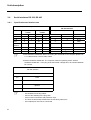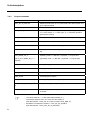
1
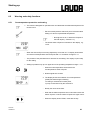
Operating Instructions Ecoline Immersion thermostats E 200, E 300 Bath/ Circulation thermostats E 206 T, E 212 T, E 215 T, E 220 T E 203, E 211, E 219, E 225 E 306, E 312, E 320, E 326 From Series Z 01 Software version 3.1 01/01 YAEE0013 LAUDA DR. R. WOBSER GMBH & CO. KG P.O. Box 1251 97912 Lauda-Königshofen Germany Phone: (+49) (0) 9343/ 503-0 Fax: (+49) (0) 9343/ 503-222 e-mail [email protected] Internet http://www.lauda.de Safety notes Before operating the equipment please read carefully all the instructions and safety notes. If you have any questions please phone us! Follow the instructions on setting up, operation etc. This is the only way to avoid incorrect operation of the equipment and to ensure full warranty protection. • Transport the equipment with care! • Equipment and its internal parts can be damaged: − by dropping − by shock. • Equipment should only be operated by technically qualified personnel! • Never operate the equipment without the bath liquid! • Do not start up the equipment if − it is damaged or leaking − the supply cable is damaged. • Switch off the equipment and pull out the mains plug for − servicing or repair − the supply cable is damaged! • Drain the bath before moving the equipment! • Have the equipment serviced or repaired by properly qualified personnel only! The Operating Instructions include additional safety notes which are identified by a triangle with an exclamation mark. Carefully read the instructions and follow them accurately! Disregarding the instructions may have serious consequences, such as damage to the equipment, damage to property or injury to personnel We reserve the right to make technical alterations! I 1 BRIEF OPERATING INSTRUCTIONS...........................................................................................1 2 CONTROL AND FUNCTIONAL ELEMENTS.................................................................................3 3 UNIT DESCRIPTION .....................................................................................................................4 3.1 Unit description......................................................................................................................4 3.2 Pumps.....................................................................................................................................4 3.3 Temperature indication, control, and safety circuit ............................................................5 3.4 Programmer (Types E 3xx only)............................................................................................5 3.5 Materials .................................................................................................................................5 3.6 Serial Interfaces RS 232, RS 485...........................................................................................6 3.6.1 Specification and interface test.........................................................................................................6 3.6.2 General information............................................................................................................................7 3.6.3 Output commands ..............................................................................................................................8 3.6.4 Data request from the thermostat.....................................................................................................9 3.6.5 Error messages.................................................................................................................................10 4 UNPACKING ...............................................................................................................................11 5 PREPARATIONS .........................................................................................................................12 5.1 Assembly and setting up.....................................................................................................12 5.2 Filling and emptying ............................................................................................................14 5.3 Bath liquids and hose connections ....................................................................................16 5.4 Connection of external circuits...........................................................................................18 5.5 Cooling the thermostats......................................................................................................20 6 STARTING UP .............................................................................................................................21 6.1 Connection to the supply ....................................................................................................21 6.2 Switching on ........................................................................................................................21 6.3 Setpoint selection (level 0) ..................................................................................................22 6.4 Menu functions ....................................................................................................................23 6.4.1 Cooling function (E 3xx only) (level 1) ............................................................................................23 6.4.2 Pump output......................................................................................................................................24 6.4.3 Setting the setpoint resolution........................................................................................................25 6.4.4 Programmer (Types E 3xx only)......................................................................................................26 6.4.4.1 Program example.........................................................................................................................26 II 6.4.4.2 Indicating/ altering of programme segments................................................................................27 6.4.4.3 Number of program running.........................................................................................................29 6.4.4.4 Starting of the programmer..........................................................................................................30 6.4.4.5 Inserting/ deleting of program segments .....................................................................................31 6.4.4.6 Holding/continuing the program ...................................................................................................33 6.4.4.7 Terminating the program .............................................................................................................34 6.4.5 Parameters ........................................................................................................................................34 6.4.5.1 Setting the proportional band of the PID-controller......................................................................35 6.4.5.2 Setting the reset time of the PID-controller ..................................................................................36 6.4.5.3 Selection of the interface .............................................................................................................36 6.4.5.4 Setting the Baud rate/ transfer rate (serial interface) ...................................................................37 6.4.5.5 User calibration ............................................................................................................................38 6.5 Warning and safety functions .............................................................................................41 6.5.1 Overtemperature protection and testing........................................................................................41 6.5.2 Low-level protection and testing ....................................................................................................42 6.5.3 Pump motor monitoring...................................................................................................................43 6.5.4 Connection floating contact ”Combination fault” 31 N ................................................................43 6.5.5 Other error messages ......................................................................................................................44 7 SAFETY NOTES ..........................................................................................................................45 7.1 General safety notes ............................................................................................................45 7.2 Other safety notes................................................................................................................45 8 MAINTENANCE ...........................................................................................................................47 8.1 Cleaning................................................................................................................................47 8.2 Maintenance and repair .......................................................................................................47 8.3 Ordering spares ...................................................................................................................48 9 TECHNICAL DATA(TO DIN 58966) .............................................................................................49 10 ACCESSORIES .........................................................................................................................53 11 CIRCUIT DIAGRAM ...................................................................................................................55 III Explanation of signs ☞ ➾ IV Danger: This sign is used where there may be injury to personnel if a recommendation is not followed accurately or is disregarded. Note Here special attention is drawn to some aspect. May include reference to danger. Reference: Refers to other information in different Sections. Brief operating instructions 1 Brief operating instructions This brief instruction shall give you the possibility to operate the unit quickly. For safe operation of the unit it is absolutely necessary to read carefully all the instructions and safety notes! 1. Assemble unit and add items as appropriate (➾ Section 5). Take care of the hose tubing connections (➾ Section 5.1. and 5.4.). 2. Fill the unit with corresponding liquid. (➾ Section 5.3.). The units are designed for operation with non-flammable and flammable liquids to EN 61010-2-010. ! Take care of the level of the bath liquid! (➾ Section 5.2.) 3. Connect the unit only to a socket with a protective earth (PE) connection. Compare the information on the rating label with the supply details. 4. Using a screwdriver, set the overtemperature cut-out point to a value clearly above ambient temperature (➾ Section 6.5.1.). 5. Switch on at the mains switch 6. Setting of the functions 30.03.99 YAEE0013 1 Brief operating instructions 2 Control and functional elements 2 Control and functional elements Clamping bracket Setting knob Pt 100 Pump housing Outlet for bath circulation Jet nozzle Heater Heating LED green; Supply ON Menu functions Mains switch Setting of overtemperature switch-off point Pump connections − inlet Pump connections − outflow Cooling coil connection Bath bridge Bath cover 30.03.99 YAEE0013 3 Unit description 3 Unit description 3.1 Unit description The immersion thermostats E 200 and E 300 have a device for fixing the immersion thermostat to the bath vessel (clamping bracket). An adapter is supplied for the deep-drawn LAUDA baths 003, 011, 019 and 025. The type designation of the Ecoline bath/circulation thermostats consists of the control unit E 200 or E 300 and the type of bath. Example: Control unit E 200 and bath 003 produces Thermostat Type E 203ö. The letter T (for "Transparent") refers to the baths made of polycarbonate. Type E 203 and all Types E 3xx are supplied with bath cover. For other baths made of stainless steel bath covers are available as accessory (➾ Section 10. Accessories). 3.2 Pumps All units are supplied with a pressure pump with vario-drive. The pump has an outlet with a rotatable bend (immersion thermostat) which is connected to the pump nipple for external thermostating circuits (bath/circulation thermostats). An additional outlet provides circulation within the bath. By turning the setting knob you can choose between both outlets or divide the flows. The pump chamber of immersion thermostats is rotatable in a restricted way to reach an optimal circulation. The pump can be used up to viscosities of 150 mm²/s during heating up. To get an optimum accuracy of control a viscosity of 30 mm²/s is recommended. One of five pump output steps can be selected using the operating menu. On small bath thermostats (e.g. E 203 or E 206 T) and with operation as bath thermostat it is advisable to use output step 1. The advantage is a low heat generation while having a uniform circulation, that means, that the unit can work without cooling down to just above ambient temperature. When operating as circulation thermostat with an external circuit it is preferable to use a larger flow setting in order to ensure a small temperature difference, especially at higher temperatures and in conjunction with oil as the bath liquid. The pump connections of Types E 3xx are fitted with M 16x1 nipples. The pump outflow connection can be closed off without causing any damage to the pump. Pump characteristics (➾ Section 9. Technical data) 4 Unit description 3.3 Temperature indication, control, and safety circuit The unit is provided with a 2-line LCD-Display with additional symbols for indicating bath temperature and settings as well as operating states. On E 3xx-Types the display has back-lightning. The setpoint is input and additional adjustments can be made using either two or three keys. Remote operation is possible via an isolated RS 232 interface A Pt 100 temperature probe is used for measuring the actual temperature and for control. A second Pt 100 serves as temperature probe for the safety circuit (overtemperature protection) which is independent of the control function A low-level cut-out switches off the heating on both poles in order to prevent dry operation of the heater. The pump is switched off through the electronics. The setting of the overtemperature cut-out is adjusted with a tool on a potentiometer and is always limited to 5 °C above the operating temperature range. A floating contact "Combination fault" is available (➾ Section 6.5.4.). All settings and fault messages are stored in the memory on supply failure or when the mains switch is set to OFF The tubular heater is controlled from a modified PID controller through a triac circuit specially designed to be unaffected by supply variations and interference. Types E 3xx have connection sockets for a solenoid valve for cooling regulation (19 H) and for the connection of flow-through coolers (34 H). 3.4 Programmer (Types E 3xx only) Types E 3xx incorporate a programmer which can be used to run temperature programmes with up to 20 temperature-time-segments (➾ Section 6.4.4). 3.5 Materials All parts which come into contact with the bath liquid are made from high-grade materials appropriate to the operating temperature. These are rust-free stainless steel, the plastics PPS, polycarbonate (bath 006 T, 015 T, 012 T, 020 T) and fluoride rubber. 30.03.99 YAEE0013 5 Unit description 3.6 Serial Interfaces RS 232, RS 485 3.6.1 Specification and interface test Computer Data RxD TxD DTR Signal Ground DSR RTS CTS ☞ Thermostat RS 232 Interface 9-pin sub-D socket ① ② 25-pin sub-D socket ① ② 9-pin sub-D socket ① ② 2 3 4 5 3 2 20 7 2 3 4 5 2 3 6 7 8 2 3 5 6 4 5 3 2 7 6 7 8 Data 5 TxD RxD DSR Signal Ground 7 8 DTR CTS RTS ① with Hardware Handshake: When connecting the thermostat to the computer please use a 1:1 cable and not a zero-modem-cable! ② without Hardware Handshake: The computer needs an operating mode: ”without Hardware-Handshake”. In the plug of the thermostat a bridge has to be inserted between Pin 7 and 8. Thermostat RS 485 interface 9-pin sub-D-socket pin Data 1 Data A 5 SG (Signal Ground) optional 6 Data B ☞ 6 − − − − − Use shielded connecting cables.. Connect the shielding to the plug case. Cover unused connectors with protection caps! The lines are electrically isolated from the remaining electronics. Unoccupied pins must not be connected! Unit description The RS 232 Interface can easily be tested with the PC connected, using the MS-Windows operating system. On Windows 3.11 with the program "Terminal" and on Windows 95 with the program "Hyper Terminal Terminal”. The RS 485 bus absolutely needs a bus-termination in form of a terminating network, which ensures a defined unattended time in the high resistance phases. The bus-terminal is defined as follows Generally this network is integrated on the plug in card of the computer (RS 485). 3.6.2 General information The interfaces operate with 1 stop bit, no parity bit and 8 data bits Transfer rate (selectable): 2400, 4800, 9600 (factory setting) or 19200 baud. RS 232 Interface: ☞ − This interface can also be handled by Hardware – Handshake (RTS/CTS) (➾ Section 3.6.1.) Values can be transferred directly from the computer to the thermostat via the commands: OUT, STOP, START (➾ Section 3.7.3.). After a correct transfer of these commands the thermostat always responds with the message "OK" followed by "CR" and "LF". (Must be read out by the computer like any other response.) RS 485 Interface: ☞ − The unit address has to be added in front of the RS 232 interface commands (possible are unit addresses 000...127 ! the address always has to have 3 digits). − Example: Transfer the setpoint temperature 30,5°C from the thermostat to the unit address 15 ! ”A015_OUT_SP_00_30.5°C”CR (➾ Section 3.6.3.). The thermostat always responds with the unit address first ! ”A015_OK” CR LF Values are transferred from the thermostat to the computer using an IN-command. (➾ Section 3.6.4.) 30.03.99 YAEE0013 7 Unit description 3.6.3 Output commands Command Explanation OUT_SP_00_XXX.XX Setpoint transfer with up to 3 places before the decimal point and up to 2 places behind OUT_SP_01_XXX.XX Pump output step 1, 2, 3, 4 or 5, OUT_SP_02_XXX.XX Operating mode of the refrigeration system (E 3xx types only) "0" = Valve closed, "1" = Valve open, "3" = Automatic operation (proportional cooling) OUT_PAR_00_XXX.XX Setting of the control parameter Xp for controller (0,5...9,9°C) OUT_PAR_01_XXX.XX Setting of the control parameter Tn (5...60 s) START switches the unit on (from stand-by) STOP switches the unit to stand-by (pump, heating, refrigeration system off) OUT_MODE_00_X Operating mode: 0 = RS 232 + keyboard, 1 = only RS 232 (A015_OUT_MODE_00_X --> RS 485) (Operating mode : 0 = RS 485 + keyboard/ 1 = only RS 485) RMP_START Starting the programmer RMP_PAUSE Stopping the programmer RMP_CONT Restart the programmer after PAUSE RMP_STOP Terminating the program RMP_RESET Deleting the program (all segments) RMP_OUT_00_XXX.XX_XXX.X X Programmer segments (max. 20) (temperature, time) RMP_OUT_02_XXX.XX Number of program running: 0...255, 0= infinite 0 = STOP ➀ If the thermostat is not connected to cooling water, 0 or 1 should be selected ☞ 8 − The blank character " " is also permissible instead of "_". − Thermostat response "OK" or in case of a fault "ERR_X" (RS 485 interface: ”A015_OK” or in case of a fault ”A015_ERR_X”) − EXAMPLE: set setpoint to 20.00°C: " OUT_SP_00_20"CR LF (RS 495 interface: ”A015_OUT_SP_00_20”CRLF) Unit description Permitted data formats -XXX.XX -XX.XX -X.XX -.XX 3.6.4 -XXX.X -XX.X -X.X -.X -XXX. -XX. -X. .XX -XXX -XX -X .X XXX.XX XX.XX X.XX XXX.X XX.X X.X XXX. XX. X. XXX XX X Data request from the thermostat The response from the thermostat is always in the fixed format "XXX.XX" for negative values "-XXX.XX" or " ERR_X" (RS 485 interface: ”A015_XXX.XX”, for negative values ”A015_-XXX.XX” or ”A015_ERR_X”). Input command Explanation IN_PV_00 Request to indicate the bath temperature IN_SP_00 Request to indicate the active setpoint IN_SP_01 Request to indicate the pump output step IN_SP_02 Request to indicate the operating mode of the refrigeration system (E 3xx types only) "0" = Valve closed , "1" = Valve open, "3" = Automatic operation (proportional cooling)➀ IN_SP_03 Request to indicate the current overtemperature switch-off point IN_PAR_00 Request to indicate the current value of Xp IN_PAR_01 Request to indicate the current value of Tn TYPE Request to indicate the unit type VERSION Request to indicate the software version number STATUS Request to indicate the unit status 0 = OK, - 1 = fault STAT Input for fault diagnosis answer XXXXX ! X = 0 no fault, X = 1 fault char. 1 from right = internal fault microcontroller 2 char. 2 from right = internal fault microcontroller 1 char. 3 from right = pump blocked char. 4 from right = low level char. 5 from right = overtemperature fault diagnosis microcontroller 1 ➁ IN_ERR_00 30.03.99 YAEE0013 9 Unit description IN_ERR_01 fault diagnosis microcontroller 2 ➁ IN_MODE_00 (A015_IN_MODE_00 -->RS485) 0 = RS 232 + keyboard/ 1 = only RS 232 interface (0 = RS 485 + keyboard/1 = only RS 485 interface) RMP_IN_00_XX Request to indicate the program segments (answer e.g 030.00_010.00 = 30.00 °C, 10 min) (1...20) RMP_IN_01 Request to indicate the current segment number, if programmer is activated RMP_IN_02 Request to indicate the number of program running (pre-set) RMP_IN_03 Request to indicate the current program running ➀ If the thermostat is not connected to cooling water, 0 or 1 should be selected. ➁ ➾Section 6.5.5. Other error messages 3.6.5 Error messages Message Explanation ERR_2 ERR_3 ERR_5 ERR_6 ERR_28 ERR_29 ERR_30 incorrect input (e.g. buffer overflow) incorrect command syntax error on value illegal value receive – frame – error (e.g. stop bit missing) Function blocked (at this time)! wait a few ms, then try again Programmer, all segments are occupied ☞ 10 RS 485 interface: Message ”A015_ERR_2”. Unpacking 4 Unpacking After the unit and accessories have been unpacked they have to be examined for possible transport damage. If there is any damage visible on the unit, the forwarding agent or the post office has to be notified so that the shipment can be examined. Standard accessories: Bath cover E 203 and on all bath/circulation thermostats E 3xx 13 mm dia. nipple union nuts (M16x1) on all bath/circulation thermostats E 3xx Closing plugs on all bath/circulation thermostats on all bath/circulation thermostats Warning label Operating Instructions on all immersion and bath/circulation thermostats 30.03.99 YAEE0013 11 Preparations 5 Preparations 5.1 Assembly and setting up a) Immersion Thermostat − Hang the thermostat into the bath to be thermostated (baths ➾ Section 10. Accessories) ☞ − In baths made of plastic the heater should not have contact to the sides of the bath! − Do not cover the ventilation opening at the back of the unit. Keep clear distance of at least 20 cm. Adjustment of the pump chamber − The fixation of the temperature probe has to be moved upwards approx. 15 mm. − Adjust the pump chamber. − Move the fixation of the temperature probe downwards again (see ill. on the left) − For all LAUDA baths (plastic and deep-drawn baths), please fix the adapter (standard accessory) on the clamping bracket. − Turn the jet nozzle to face diagonally into the bath. The outflow for the bath circulation can then be closed. − Turn the setting knob to the left (see. ill. 1.) Adjustments of the pump outflows ill 1 Setting knob turned anticlockwise 12 ill 2 Setting knob medium position ill 3. Setting knob turned clockwise Preparations Operation with cooling coil (➾ Section 10. Accessories) − Pull the clamping bracket to the back for fixing the cooling coil while releasing it with a screwdriver. − Push the cooling coil on the clamping bracket. − Install the clamping bracket again. Operation with fixing rod (➾ Section 10. Accessories) − Pull the clamping bracket to the back while releasing it with a screwdriver. − Install the fixing rod together with the clamping bracket. Operation with external circuit (➾ Section 5.4.) − The immersion thermostats have to be fixed carefully at the bath, for they must not fall into the bath. − In that case don’t touch the bath liquid! Pull out mains plug immediately! a) Bath/Circulation thermostats − Place the unit on a flat surface. − Do not cover the ventilation openings at the back. ☞ − Keep a clear distance of at least 20 cm. − Put the control unit with the bath bridge on the bath (Types E 2xx only) − When operating without an external consumer (bath thermostat) the setting knob has to be turned so that the flow comes out of the outlet for bath circulation (➾ ill. 3, Section 5.1.). 30.03.99 YAEE0013 13 Preparations b) Operation with external consumer (Circulation thermostat) (➾ Section 5.4.) − At bath temperature above 70°C the label supplied must be affixed on the bath in a clearly visible position. − When operating as bath thermostat without external consumer the pump pressure outflow has to be closed (use closing plugs) or linked to the return. 5.2 Filling and emptying Filling − Close the drain cock (Types E 3xx only). − Fill baths up to a maximum level of 20 mm below the bath bridge. − Optimum operation at 20-40 mm below the bath bridge. − Operation is possible down to 60 mm below the bath bridge. − The low-level cut-out operates at approx. 90 mm below the bath bridge ☞ 14 − When using thermal oils it is necessary to allow an expansion of approx. 8 %/100 °C. − When operating with an external consumer the total expansion takes place in the bath. Preparations Emptying − Switch off the thermostat, pull out the mains plug! a) Immersion thermostat, Bath/ Circulation thermostat (Types E 2xx) − Unscrew the immersion thermostat or take off the control unit with the bath bridge. − Drain the bath b) Bath/Circulation thermostat (Types E 3xx) are equipped with a drain cock --> Attach the hose on the drain cock and drain the bath. ☞ − The units are designed for operation with non-flammable and flammable liquids to EN 61010-2-010! Flammable liquids can be operated up to no more than 25°C below the firepoint (➾ Section 5.3.). − Observe the appropriate regulation when disposing used thermostating liquid. − When connecting an external consumer take care that the level of the bath liquid does not drop too much ! fill in bath liquid if necessary. Do not drain the thermostating liquid when it is hot or very cold (below 0°C)! 30.03.99 YAEE0013 15 Preparations 5.3 Bath liquids and hose connections Bath liquids Firepoint Working temperature range Chemical Designation Viscosity (kin) Viscosity (kin) at Temperature Former designation from °C to °C at 20°C mm²/s mm²/s water +5...+90 deionised -- -- -- LAUDA Designation Ref.No. Quantity 5l 10 l 20 l water ➀ Kryo 30 ➁ G 100 ➁ -30...+90 Monoethyleneglycol/water 4 50 at -25°C -- LZB 109 LZB 209 LZB 309 Kryo 50 SK Super Frigor -50...+95 Silicone oil 6 35 at -50°C > 139 LZB 103 LZB 203 LZB 303 Kryo 20 160 MS -20...+180 Silicone oil 11 28 at -20°C > 230 LZB 116 LZB 216 LZB 316 Ultra 350 330 SCB +30...+200 synthetic thermal oil 47 28 at +30°C > 240 LZB 107 LZB 207 LZB 307 Therm 230 RDS 50 +60...+230 Silicone oil 44 28 ... +60°C > 362 LZB 117 LZB 217 LZB 317 ☞ ① At higher temperatures ! Evaporation losses ! Use bath covers (➾ Section 10. Accessories). Distilled water or fully deionised water must only be used with the addition of 0,1g sodium carbonate/l water, otherwise ! danger of corrosion! ➁ Water content falls after prolonged operation at higher temperatures ! mixture becomes flammable (flash point 128 °C). ! Check the mixture ratio with a densiometer. − When selecting bath liquids it should be noted that performance must be expected to worsen at the lower limit of the operating temperature range due to increasing viscosity. The full operating range should only be utilised if really necessary. − The operating ranges of the bath liquids and tubing represent general data which may be limited by the operating temperature range of the unit. Silicone oil causes pronounced swelling of Silicone rubber ! never use Silicone oil with Silicone tubing! DIN Safety data sheets are available on request 16 Preparations Hose connections a) Elastomer tubing Tubing type Int. dia. Ø mm Temperature range °C Application Ref. No. Perbunan tubing, uninsulated 9 0 to 120 for all bath liquids RKJ 011 Perbunan tubing, uninsulated 12 -0 to 120 for all bath liquids RKJ 012 Perbunan tubing insulated 12 ext. dia. 35mm approx. -60 to 120 for all bath liquids LZS 008 Silicone tubing, uninsulated 11 -30 to 100 water, water/glycol mixture RKJ 059 Silicone tubing insulated 11 ext. dia. 35mm approx. -60 to 100 water, water/glycol mixture LZS 007 Viton 11 -60 to 200 for all bath liquids RKJ 091 − Silicone oil causes pronounced swelling of Silicone rubber ! never use Silicone oil with Silicone tubing! − Protect tubing with hose clips against slipping off. b) Metal hoses for Types E 3xx, rust free stainless steel, with M 16 x 1 union nut 10 mm int. Dia Type MC 50 MC 100 MC 150 MC 200 Pump connection link Length cm 50 100 150 200 20 MK 50 50 MK 100 MK 150 MK 200 Pump connection link 100 150 200 20 Notes Ref. No. With single insulation " " " " LZM 040 LZM 041 LZM 042 LZM 043 LZM 044 with foam insulation for low temperatures " " " " LZM 052 LZM 053 LZM 054 LZM 055 LZM 045 30.03.99 YAEE0013 17 Preparations 5.4 Connection of external circuits a) Immersion thermostats − Push 11-12 mm int. dia. tubing (➾ Section 5.3.) directly onto the jet nozzle and connect it to the external circuit. − Hang the return tubing into the bath and fix it! − We recommend to use the pump set (➾ Section 10. Accessories). In this case − screw on the pump connectors. − install the connecting tube. − Using the setting knob at the pump outflows, divide up the pump flow in accordance to the thermostating task.(➾ Section 5.1) − Position ➀ ! maximum flow in the external circuit, the setting knob is turned anticlockwise. − Position ➁! flow passes through pump outflow and outlet for bath circulation, the setting knob is in medium position. − Position ➂ ! external circuit is closed and the outlet for bath circulation fully open, the setting knob is turned clockwise. − Operate the setting knob only when the bath contents are near ambient temperature. − When no tubing is connected, close the pump outflow with closing plugs even in position ➂. 18 Preparations b) Bath/Circulation thermostat − Connect 11-12 mm int. dia. tubing (for Types 3xx use metal hoses) (➾ Section 5.3.) to the pump connector − Pump outflow connection always in front, return connection always at the back. ☞ − If the cross-section of the tubing is too small ! temperature drop between bath and external system due to low flow rate. Increase the bath temperature appropriately. − Always ensure the maximum possible flow cross-section in the external circuit! − On Types E 3xx, when tightening the union nut hold on to the pump nipple with a SW 14 spanner (see ill.)! − When the external consumer is placed at a higher level than the thermostat, the pump is stopped and air penetrates into the thermostating circuit the external liquid may drain down into the bath even with a closed system ! danger of flooding the thermostat! − Protect tubing with hose clips against slipping off! − When no external circuit is connected to the thermostat, the outflow connection must be closed (use closing plugs) or linked to the return! 30.03.99 YAEE0013 19 Preparations 5.5 Cooling the thermostats At bath temperatures down to just above ambient temperature (approx. 2 – 10°C) it is possible to work without cooling. Additional cooling is required for lower temperatures Immersion thermostat. ! attach the cooling coil (➾ Section 5.1.). Bath/Circulation thermostats ! fitted with cooling coil, as standard.. Cooling possibilities . down to 20 °C Mains water ! keep the water consumption as low as possible! . down to –30°C flow-through cooler DLK 10/ DLK 25 (depending on bath size and temperature) ➾ Section 10. Accessories ! use water/glycol mixture (ratio 1:1). Mains supply outlet 34H (types E 3xx only) ! Connection socket for through-flow- cooler (Countersocket ➾ Section 10). Mains supply 230V will be switched off in case of fault. Consumption of current 2A max. ☞ . 20 − Use insulated tubing! − When thermostating an external system the equipment must be arranged in the following order: thermostat ! external circuit ! flow-through cooler ! thermostat For Types E 3xx ! Connection of a solenoid valve is possible for controlled cooling with mains water in combination with a cooling coil. (connection socket 19H, 230V, max. 0,2A). Within a temperature range of approx. 15 to 100 °C the cooling is automatically adjusted to the requested demand. A set of solenoid valves is necessary (➾ Section 10. Accessories). It is absolutely necessary to use hose clips. Fasten the outflow tube in the drain. Starting up 6 Starting up 6.1 Connection to the supply Compare the supply voltage against the data on the rating label. Model according to EMC directive EN 61326-1 Class B.* − Connect the unit only to a grounded mains power socket (PE). − No warranty when the thermostat is connected to a wrong supply! − Without external circuit ensure that the pump pressure outflow is closed or linked to the pump return. − Ensure that the unit is filled in accordance with Section 5.2.! 6.2 Switching on − Using a screwdriver set the overtemperature switch-off point to a value clearly above ambient temperature. − Switch on at the mains switch. The green LED for "Supply ON" lights up. ! − A tone sounds for approx. 0,25 s. 0,25s − The unit self-test starts up. All display segments and symbols light up for approx. 1 s. Then the software version is indicated for approx. 1 s. − Display shows the actual bath temperature (above) (resolution 0,05 °) and the setpoint. The pump starts up. The values which were active before switching off are entered. ☞ − If necessary add more bath liquid to replace the amount pumped out to the external circuit. − If the pump does not purge the system immediately. The unit may switch off again although it is filled sufficiently (only when starting up for the first time).. * Notic only valid for EU countries 22.02.01 YAEE0013 21 Starting up ! − A double signal tone sounds. − The display for low-level (LEVEL) appears. − The fault triangle is flashing − Press the key. If necessary repeat several times. − Also press the key if the unit had switched off under a fault condition. 6.3 Setpoint selection (level 0) or − Input the setpoint with one of the keys. − Speeding the setting process by: a) continuous pressing the keys or b) pressing one key (holding it down) and shortly pressing the other key. − Briefly releasing (1 s) the key (s) and again pressing one of the keys moves the cursor one place to the right. − Display flashes 4 s " the new value is accepted automatically, or − Value is entered immediately with this key. ☞ 22 − For safety reasons the setpoint can only be adjusted up to 2 °C above the upper limit of the operating temperature range of the particular unit type Starting up 6.4 Menu functions − Switching from setpoint selection (level 0) to level 1 using the key or − Within one level it is possible to scroll using the keys. − In principle, after each setting has been made it is entered automatically after approx. 4 s or − Settings are entered immediately on operating this key 6.4.1 Cooling function (E 3xx only) (level 1) − The display shows the current bath temperature, COOL and the set operating mode. To alter the setting, press the key on the left. − The display flashes (approx. 4 s). or During this time start to set the operating mode with one of the keys 0 = solenoid valve CLOSED 1 = solenoid valve OPEN A = unit operates valve as required (proportional cooling) − Forward with key to "pump output" or − with key back to level 0 (setpoint input). ☞ − If the thermostat is not connected to cooling water, setting 0 or 1 should be selected. − When using a through-flow chiller (DLK) at socket 34 H, this is operating continuously except in the case of a fault or if the pump is set to 0. 30.03.99 YAEE0013 23 Starting up 6.4.2 Pump output − For setting the pump output starting from level 0, press the key shown on the left (on Types E 2xx). and 1x − On Types E 3xx press this key combination shown on the left or − move forward from COOL function with this key(types E 3xx only). − The display shows the current bath temperature, PUMP and the current output step. To alter the setting press the key shown on the left. − Display flashes (approx. 4 s). or − During this time start to set the required step with one of the keys. 0 = pump stopped, heating off 1 = low pump output 2 , 3 , 4 = medium pump output 5 = maximum pump output − The pump responds immediately (can be heard). (Setting is entered after approx. 4 s ➾ Section 6.4.) − Move forward with key to "Selecting the setpoint resolution" or − back with the key to "COOL - function" (E 3xx) or to "Setpoint selection" (E 2xx). 24 Starting up 6.4.3 Setting the setpoint resolution and 2x and 1x − To set the setpoint resolution from level 0 press the key combination on the left (top one on E 3xx, bottom one on E 2xx) or − move forward with the key from the PUMP-function. − The current bath temperature, RES and the current setpoint resolution are indicated. − To alter the setting, press the key on the left. − Display flashes (approx. 4 s). or − During this time, start to set the required resolution with one of the two keys. normal setting ! 0,1 = 0,1 °C setpoint resolution, or 0,01 = 0,01 °C setpoint resolution. During setpoint input only S is indicated instead of SET. − Forward with the key to "parameter level" (E 2xx only) or to "programmer" (E 3xx only) or − with key back to "PUMP“. 30.03.99 YAEE0013 25 Starting up 6.4.4 Programmer (Types E 3xx only) − To view or to set the programmer, starting from level 0 (setpoint input) press the key combination on the left, or and 3x − from RES function scroll with this key. − The display shows PGM (programmer). Data for up to 20 program segments can be input there. 6.4.4.1 Program example Segment 1 2 3 4 5 6 Temperature 30,0 50,0 70,0 70,0 60,0 30,0 Time 20 20 40 10 30 0 Segment 1 2 3 4 5 6 7 Temperature 30,0 50,0 50 ➀ 70,0 70,0 60,0 30,0 Time 20 20 20 ➀ 20 ➁ 10 30 0 7 ➀ A new segment has been inserted after segment ➁ The time at segment No. 3 has been altered (➾ No. 2 (➾ Section 6.4.4.5.) Section 6.4.4.2.) 26 Starting up 6.4.4.2 Indicating/ altering of programme segments − When PGM appears on the display (therefore proceed as described in 6.4.4.) press the key on the left. − The display shows RUN. Here the programmer can be started (➾ Section 6.4.4.4.) − Forward with key until EDIT appears.. − Here the program segments can e.g. be indicated and altered. To do so press the key. − The display indicates 3 variables: segment number (a), segment end temperature (b) and segment time (c). − EXAMPLE: segment number 1, b = 30,0 °C, c = 20 min. The bath liquid has to be heated up or cooled down to 30 °C within 20 min. ☞ − When having deleted the programme example the variables on the display show 0. Before altering the segments it is necessary to insert new segments (➾ Section 6.4.5.5.) or − These keys can be used to scroll through the different variables. − Sequence with the key:: 1 (a) ! 30,0 °C (b) ! 20 (c) ! 50,0 ° (2. Segment), ! 20 (2. Segment). − When the segment number is flashing, pressing the key leads directly to the menu for inserting or deleting segments (➾ Section 6.4.4.5.). Otherwise scroll e.g. from segment time back to segment temperature and segment number. 30.03.99 YAEE0013 27 Starting up − The variable currently activated flashes quickly (here the segment number). − To alter the required variable start with this key or − If e.g. the segment number is flashing, all segments can be indicated in sequence by pressing one of the two keys, or − If segment temperature or segment time are flashing, the required temperature or time can be input by pressing the key and then using the other two keys. − Segment temperature: 2 °C max. above the upper limit of the operating temperature range of the particular thermostat type. − Segment time: 0...255 min. − After having changed the segments move forward with key to END 1. Forward with the key to EDIT. − with the key to END and then − back to level 0 with the key, or 2. with the key back to LOOP (➾ Section 6.4.4.3.) resp. to RUN (➾ Section 6.4.4.4.) 28 Starting up ☞ − While the programmer is in operation segments can be altered (including the current segment) and new segments can be inserted. All segments can also be deleted at each time (except the current segment) (➾ Section 6.4.4.5.) BUT: If the new segment time is shorter than the segment time which has already elapsed, the next segment is activated. − If a segment time longer than 255 min is required, this time must be distributed over several consecutive segments. 6.4.4.3 Number of program running − From level 0 proceed as described under 6.4.4. When PGM appears on the display, press the key on the left − The display first shows RUN. − Forward with key until LOOP appears, or − from EDIT with this key to LOOP. − Here the number of program running can be input. Therefore press the key. The display is flashing for approx. 4 s. or − During this time start to set the required number of running with one of the two keys. Input possibility: 0...255 ( 0 = infinite). − Then with the key back to RUN (➾ Section 6.4.4.4.), or − with key until END and then 30.03.99 YAEE0013 29 Starting up − with key back to "setpoint selection". (level 0) 6.4.4.4 Starting of the programmer − From level 0 proceed as described under 6.4.4. When PGM appears on the display, press the key on the left − The display shows RUN, or − with key from EDIT resp. LOOP until RUN appears, then − start the programme with the key on the left. The setpoint level (level 0) is then on display. ☞ 30 − During the start the current setpoint is accepted as the starting value. − If the programmer is activated: level 0 shows PGM XXX.XX instead of SET XXX.XX (setpoint temperature), with PGM flashing short (short off, long on). − Setpoint can not be input with 0,01 °C resolution (only possible via RS 232 interface.) − General Rule: Programmer can also be loaded and operated via the RS 232 interface. Starting up 6.4.4.5 Inserting/ deleting of program segments 1. From level 0 proceed as described under 6.4.4. When PGM appears on the display, press the key on the left.. 2. The display shows RUN (or STOP if the programmer had been started). Scroll with this key until EDIT appears. 3. The display shows EDIT, press the key. 4. Segment number is flashing, press the key. or − Using the keys, select the segment number behind which the new segment has to be inserted. EXAMPLE: Section 6.4.4.1.: A new segment has to be inserted after segment 2. Select segment 2 with the keys. − With the key forward until NEW appears. The segment number ”2” behind which the new segment and the segment temperature are indicated. − Press the key, the display shows NEW as well as the segment number and temperature of the new segment. − Then jump with the key to segment temperature or segment time and start input with the key, then or − using both keys input the required segment time and segment temperature, then continue as described below (step 5-8) 30.03.99 YAEE0013 31 Starting up ☞ − When a new segment is inserted, all subsequent segments are shifted on by one position.( ➾ example Section 6.4.4.1). − When 20 segments are inserted, the last one will disappear when a new segment will be input. − New segments can also be inserted while the programmer is activated. or − In order to delete a segment, proceed as above step 1-4. − Using the keys, select the segment number which has to be deleted. − Scroll forward with the key until DEL appears. Next to it the segment number to be deleted is shown. − Press the key, the segment is deleted. 5. Then with the key forward to END. 6. with the key to EDIT, then 7. with the key to END and 8. with the key back to level 0. ☞ − When a segment is deleted, all subsequent segments move forward by one position. − When the programmer is activated, the currently active segment cannot be deleted. − To input a segment time longer than 255 min it has to be split between several consecutive segments. 32 Starting up 6.4.4.6 Holding/continuing the program When the programmer is activated, the programme can at any time be held and be continued again. For this 1. from level 0 proceed as described under 6.4.4. When the display shows PGM, press the key 2. The display shows STOP. Scroll forward with the key until PAUSE appears − The currently running segment is shown after PAUSE, press the key. − The program is held. Scroll forward to END, then press the key to return to level 0. ☞ − When the program is held with PAUSE, the display at level 0 no longer shows SET XXX.XX (set temperature) but PGM XXX.XX, with PGM not flashing. − To continue the program, proceed as described in steps 1-2 above, but scroll forward until the display shows CONt. The segment number of the programmer during which the program was held, is shown after CONt. − Press the key, the program continues, the programmer jumps back to level 0. ☞ − When the program is continued, the display PGM XXX.XX at level 0 is again flashing. − If there is a fault, the program is stopped by PAUSE. After the fault has rectified, the system has to be reset with CONt. 30.03.99 YAEE0013 33 Starting up 6.4.4.7 Terminating the program − From level 0 proceed as described under 6.4.4. When the display shows PGM, press the key. − The display shows STOP. The current segment is indicated after STOP. Press the key, the programme is terminated immediately. − With the key, forward to END, then − with the key back to level 0. 6.4.5 Parameters and 4x − Directly from level 0 (setpoint selection) press the key combination on the left (on E 3xx), and 2x − on E 2xx , or − forward with the key from PGM function − Here it is possible to switch over to level 2. Press the key on the left, continue with Section 6.4.5.1. or − with key to step END. − End of the menu. − Return to level 0 (setpoint selection) with the key on the 34 Starting up left, or − with key back to programmer (E 3xx only) or to "Setting the setpoint resolution" (E 2xx). 6.4.5.1 Setting the proportional band of the PID-controller and 4x and 2x − Directly from level 0 (setpoint selection), press the key combination on the left (top one on E 3xx, bottom one E 2xx), until the PARA -function is reached, then − switch to level 2 from PARA (see above) with key on the left. or − Within this level it is possible to scroll with the keys. − The display shows the current bath temperature Xp and the current setting. To alter the setting press the key on the left. Available settings from 0,5 to 9,9 °C . (➾ Section 6.4.5.2. Note). (➾ Section 9. Technical data) ☞ − Display flashes (approx. ca. 4 s). or − During this time start to set the required value with one of the two keys. − Forward with the key to "Setting the reset time" or − with the key back to "PARA". 30.03.99 YAEE0013 35 Starting up 6.4.5.2 Setting the reset time of the PID-controller and 4x and 2x − Directly from level 0 (setpoint selection), press the key combination on the left (top one on E 3xx, bottom one E 2xx), until the PARA function is reached, then and 1x − switch to level 2 and move forward with the keys on the left. − The display shows the current bath temperature, Tn and the current setting. To alter the setting, press the key on the left. ! Possible adjustment from 5 to 60 s − The display is flashing (approx. 4 s). − During this time, start to set the required value with one of the two keys. or − Forward with the key to "Selection of the interface" or − with key back to "Setting the proportional band“. ☞ 6.4.5.3 − The control parameters are pre-set to suit the unit type. Normally no change is required. Some adjustment is necessary only when using Silicone oil and with very stringent demands on short-term stability. If there are control fluctuations, increase the values for Xp and Tn. If the setpoint is not reached ! select smaller values. The derivative time Tv (D-part) is altered automatically through a fixed factor to Tn. (Standard settings of control parameters and pump ➾ Section 9. Technical data) Selection of the interface and 4x and 2x 36 − Directly from level 0 (setpoint selection), press the key combination on the left (top one on E 3xx, bottom one Starting up E 2xx), until the PARA function is reached, then and 2x − switch to level 2 and move forward with key on the left. − The display shows the current bath temperature and the currently set interface. To alter the setting press the key. or − Display flashes (approx. 4 s.). During this time start to set the required interface with one of the keys. − Having chosen the RS 485 interface press the key. − The display shows the current bath temperature, ADR and the current unit address (e.g.. 15). Press the key, display flashes (approx. 4 s.). or − During this time start to set the required unit address. (possible setting: 000...127) − Forward with key to ”Setting the baud rate” or − back with key to ”Selection of the interface” resp. when pressing the key twice you return to ”Setting the reset time...”“ 6.4.5.4 Setting the Baud rate/ transfer rate (serial interface) and 4x and 2x − Directly from level 0 (setpoint selection), press the key combination on the left (top one on E 3xx, bottom one 30.03.99 YAEE0013 37 Starting up E 2xx), until the PARA function is reached, then and 3x − switch to level 2 and move forward with key on the left. − The display shows the current bath temperature, KBD and the current setting. To alter the setting press the key. − Display flashes (approx. 4 s). or − During this time, start to set the required value with one of the two keys. Settings available: 2400, 4800, 9600 or 19200 baud − Forward with key to "user calibration" or − with key back to "Selection of the interface". 6.4.5.5 User calibration ☞ − Remove the external consumers and switch the setting knob of the pump to right side. (➾Section 5.4). − A reference thermometer with necessary accuracy is required. Otherwise the factory calibration should not be altered. The reference thermometer has to be inserted far enough and long enough into the bath. − It is not allowed to calibrate to more than ± 3 °C. Multiple calibration to more than ± 3 °C cause internal faults (after 2 min ”E1006” or ”e16”). − The factory calibration will be lost through overwriting ! please work carefully!!! and 4x and 2x 38 − Directly from level 0 (setpoint selection), press the key combination on the left (top one on E 3xx, bottom one E 2xx), until the PARA-function is reached, then Starting up − switch to level 2 and move forward with key on the left. and 4x >2,5 s 1. The display shows CAL and the current bath temperature. To carry out a calibration, press the key longer than 2.5 s. 2. The actual value appears. or 3. Input the value indicated on the reference thermometer with one to the two keys. 4. The additive calibration must be entered with the key shown on the left. 5. Forward with key to "END", then 6. Switch back to level 0 or 7. with key back to "Setting the transfer rate". 30.03.99 YAEE0013 39 Starting up Example a) Insert a suitable thermometer into the bath (long enough and far enough). b) Remove the external consumers and turn the setting knob of the pump outflows to the right side. c) Set the setpoint to a temperature where you use to work (e.g. set the setpoint to 45°C (➾ Section 6.3.) d) Wait until the actual bath temperature has reached the setpoint temperature of 45°C and until the indication on the reference thermometer does not change any more. e) Remove the reference thermometer, which shows e.g. 44,8 °C. f) Select CAL on the display and go forward as mentioned under point 1-7 (see above).The actual bath temperature switches from 45°C to 44,8°C and the unit starts to heat up until the actual bath temperature has reached 45°C. (! the reference thermometer should also indicate 45°C). 40 Starting up 6.5 Warning and safety functions 6.5.1 Overtemperature protection and testing ☞ − The units are designed for operation with non-flammable and flammable liquids to EN 61010-2-010! − Set the overtemperature switch-off point. Recommended setting 5°C above required bath temperature. ☞ − Not higher than 25 °C below the firepoint of the bath liquid (➾ Section 5.3.). − The actual switch-off point is indicated on the display, e.g. 110°C. ☞ − When the switch-off point is being adjusted by more than 2°C ! display shows MAX and actual overtemperature switch-off point with 1°C resolution for approx. 4 s. − The position of the potentiometer is decisive for the setting. The display is just a help for the setting. − Setting is possible only up to a upper limit of the operating temperature range + 5 °C. " − When the bath temperature arises above the overtemperature switch-off point. 1. Double signal tone sounds. 2. The display shows the indication for overtemperature (TEMP) the fault triangle is flashing ! heating is switched off on both poles, ! pump is switched off by the electronics − Rectify the cause of the fault. − Wait until the bath temperature has cooled down below the switch-off point or set the switch-off point at a higher value. . − When the display shows TEMP, reset with the key. 30.03.99 YAEE0013 41 Starting up ☞ − Before the unit is run is running unattended for longer periods overtemperature protection should be tested. Therefore: − Turn the potentiometer slowly anticlockwise. ! The unit must switch off at the bath temperature. − Step 1 - 2 (see above) must follow. − Set the overtemperature switch-off point again above the bath temperature and wait until the indication TEMP appears on the display, then − reset with the key. 6.5.2 Low-level protection and testing " − Double signal tone sounds, if the bath liquid falls so much that the heater is no longer covered with liquid completely. 1. The display shows LEVEL (low-level) and the fault triangle is flashing ! heating is switched off on both poles, ! pump is switched off by the electronics 2. Top up the bath ➾ Section 5.2 and reset with the key. ☞ − If necessary repeat several times in case that the pump does not purge immediately. − Testing at regular intervals by lowering the bath level. Place a hose on the pump connector and pump some of the bath liquid into a suitable container. − Step 1 - 2 must follow. 42 Starting up − Bath temperature during this test not below 0°C or higher than 50°C, otherwise danger of burn injuries ! − If there is any irregularity when testing the safety devices, switch off the unit immediately and pull out the mains plug ! − Have the unit checked by the LAUDA service or the local service organisation! 6.5.3 Pump motor monitoring ☞ " − In case of pump motor overload or a blockage the heating and the pump are switched off. − Double signal tone sounds. − The display shows PUMP and the fault triangle is flashing − Rectify the cause of the fault, i.g. clean the pump or check the viscosity, then − reset with the key. − If several faults appear simultaneously, they have to be reset individually 6.5.4 Connection floating contact ”Combination fault” 31 N (Alarm out) 3-pole locking connector 1 = common, 2 = n.c. (make) , 3 = n.c. (break). When the unit is o.k. 1 and 3 are closed (see ill.). Max contact rating: 0.2A 24 V. 3-pin plug (➾ Section 10. Accessories). ☞ − Contact operates in case of error at overtemperature protection, low-level protection, pump monitoring or any other error message. 30.03.99 YAEE0013 43 Starting up 6.5.5 Other error messages − E 0 etc. is flashing in the bottom line. ! various temperature probe faults. ! pump fault, proceed as in Section 6.5.3. ☞ − If the fault report is repeated ! pull out the mains plug and try whether the motor can be rotated by the fan blade inserting a screwdriver into the ventilation opening at the back of the unit. − Error code 0 ...255 ! microprocessor error. − Error code 1000...1255 ! slave processor error. − Indication can be used for remote diagnosis. − After rectifying the fault, reset with the key. 44 Safety notes 7 Safety notes 7.1 General safety notes A laboratory thermostat is intended for heating and pumping liquids according to the needs of the user. This leads to hazards by high temperatures, fire, and the general hazards by the use of electrical energy. The user is largely protected through the application of the appropriate standard specifications. Additional hazards may arise from the type of material being thermostated, e.g. when going above or below certain temperature levels or through breaking of the container and reaction with the thermostating liquid. It is not possible to cover all possibilities; they remain largely within the responsibility and the judgement of the user. The unit must only be used as intended and as described in these Operating Instructions. This includes operation by suitably instructed qualified personnel The units are not designed for use under medical conditions according to EN 60601-1 or IEC 601-1 ! 7.2 Other safety notes • Connect the unit to a grounded mains power socket. • Parts of the bath cover may reach surface temperatures above 70 °C when operating at higher temperatures. Take care when touching it! • Use suitable hoses ➾ Section 5.3. • Protect tubing with hose clips against slipping off. Prevent kinking of tubing! • Check tubing from time to time for possible material defects. • Heat transfer tubing and other hot parts must not come into contact with the supply cable! • When using the thermostat as circulation thermostat, failure of tubing may lead to leaking of hot liquid and become a danger to personnel and objects. • When no external consumer is connected to the thermostat the pump outflow connection must be closed (use closing plugs) or linked to the return. • Don’t change the pump connections with the connections of the cooling coil! • Allow for expansion of the bath oil at elevated temperatures 30.03.99 YAEE0013 45 Safety notes • Depending on the bath liquid used and the mode of operation it is possible for toxic vapours to be produced. Ensure appropriate ventilation! • Immersion thermostats have to be fixed carefully at the bath vessels! • Only use bath vessels which are appropriate for the intended operating temperatures! • When changing the bath liquid from water to oil, for temperatures above 100 °C, carefully remove all traces of water, also from tubing and from the external consumer, otherwise ! danger of burns through delayed boiling! • The cooling coil with the cooling water has only to be used for operating temperatures below 100°C. At higher temperatures! danger of hot vapour to be produced! • Always pull out the mains plug before cleaning, maintenance or moving the thermostat! • Repairs on the control unit and the refrigeration system must be carried out by properly qualified personnel only! • Values for temperature control and indicating accuracy apply under normal conditions according to DIN 58966. High-frequency electromagnetic fields may under special conditions lead to unfavourable values. This does not affect the safety. 46 Maintenance 8 Maintenance 8.1 Cleaning Before cleaning the unit, pull out the mains plug! The unit can be cleaned with water adding a few drops of detergent (washing up liquid), using a moist cloth.. Water must not enter the control unit! ☞ − Carry out appropriate detoxification if dangerous material has been spilled on or inside the unit. − Method of cleaning and detoxification are decided by the special knowledge of the user. In case of doubt please contact the manufacturer! 8.2 Maintenance and repair − Before any maintenance and repair work pull out the mains plug! − Repair on the control unit must only be carried out by properly qualified personnel! LAUDA thermostats are largely maintenance-free. If the thermostating liquid becomes dirty it has to be replaced (➾ Section 5.2.). ☞ − If a fuse blows (! supply indication not alight) fit only fuses as specified (2 x T 16 A; 1 x T 2,5 A, size 5 x 20 ! fuses are inside the unit). UL 487-1 F3; T 2,5 A F1; T 16 A F2; T 16 A 30.03.99 YAEE0013 47 Maintenance 8.3 Ordering spares When ordering spares please quote instrument type and serial number from the rating label. This avoids queries and supply of incorrect items. We shall always be happy to deal with queries and to receive suggestions and criticism LAUDA DR. R. WOBSER GMBH & CO.KG P.O. Box 1251 97912 Lauda-Königshofen GERMANY Phone: (+49) (0) 9343/ 503-0 Fax: (+49) (0) 9343/ 503-222 E–mail [email protected] Internet http://www.lauda.de 48 Technical data 9 Technical data(to DIN 58966) Common technical data E 200 E 300 types starting with 2 Ambient temperature range types starting with 3 °C 5 to 40 Setting resolution °C 0.1/ 0.01 Indication resolution °C 0.05 Indication accuracy °C ± 0,2 °C additive re-calibration ➁ Temperature control ± °C 0,01 Safety features ➀ FL Additional functions Power consumption LCD Display two line 230 V;50/60 Hz 115 V; 60 Hz 100 V:50/60 Hz kW Back light two line LCD-Display, outputs for solenoid valve for controlled cooling and through- flow cooler, programmer 2.3 1,4 1,1 ➀ FL: suitable for flammable and non-flammable liquids; NFL: only suitable for non-flammable liquids ➁ ➾ Section 7.2. last item Immersion thermostats E 200 Operating temperature range ➀ " with water cooling Operating temperature range ➁ Interface Heater 230 V; 50/60 Hz power 115 V; 60 Hz 100 V; 50/60 Hz Pump type Max. discharge pressure ➂ Max. flow rate➂ Pump connections Bath depth ➃ Usable depth ➃ Overall size (WxD) Height (H) Weight Ref. No. 230 V; 50/60 Hz 115 V; 60 Hz 100 V; 50/ 60Hz E 300 °C 25 to 200 °C 20 to 200 °C -20 to 200 RS 232,. RS 485 bar l/min mm mm mm mm mm kg RS 232, RS 485 2.25 1,3 1,0 pressure pump with choice of 5 output steps 0.4 20 nipples 13 mm dia. nipples 13mm dia. (M16x1) min 150 min 100 125x133 315 3 LCE 0222 LCE 0223 LCE 4222 LCE 4223 LCE 6222 LCE 6223 ➀ at pump output step 1 ➁ with additional cooling ➂ at pump output step 5 ➃ baths ➾ section 10. Accessories 30.03.99 YAEE0013 49 Technical data Bath/Circulation thermostats E 203 E 219 Operating temperature range ➀ “with water cooling Operating temperature range ➁ 0 °C °C 23 to 150 20 to 150 -20 to 150 Heater 230 V; 50/60 Hz kW 2.25 power 115 V; 60 Hz 100 V; 50/60 Hz Pump type Max. discharge pressure ➂ Max. flow rate ➂ Pump connections Max. bath volume Bath Bath opening (WxD) Bath depth ➃ Usable depth ➃ Height top edge of bath Overall size (WxD) Height Weight Ref. No. Ref. No. 230 V; 50/60 Hz 115 V; 60 Hz 100 V; 50/ 60Hz E 225 1,3 bar l/min mm l mm mm mm mm mm mm kg 230 V; 50/60 Hz 115 V; 60 Hz 100 V; 50/ 60Hz Operating temperature range ➀ “ with water cooling Operating temperature range ➁ Heater power 230 V; 50/60 Hz 115 V; 60 Hz 100 V; 50/60 Hz Pump type Max. discharge pressure ➂ Max. flow rate ➂ Pump connections Max. bath volume Baths Bath opening (WxD) Bath depth ➃ Usable depth ➃ Height top edge of bath Overall size (WxD) Height Weight 50 E 211 °C °C °C kW bar l/min mm l mm mm mm mm mm mm kg 1,0 pressure pump with choice of 5 output steps 0.4 17 nipples 13 mm dia. 3.5 12 18 25 deep-drawn inner vessel, steel casing painted 135x105 300x190 300x365 300x365 150 150 150 200 130 130 130 180 178 178 178 228 168x271 331x360 331x536 331x536 349 349 349 399 6 9 10 12 LCB 0692 LCB 4692 LCB 6692 LCB 0694 LCB 4694 LCB 6694 LCB 0696 LCB 4696 LCB 6696 LCB 0698 LCB 4698 LCB 6698 E 206 T E 212 T E 215 T E 220 T 23 to 100 20 to 100 -20 to 100 2.25 1,3 1,0 pressure pump with choice of 5 output steps 0.4 17 nipples 13 mm dia. 7 13 15 20 polycarbonate 130x285 300x175 275x130 300x350 160 160 310 160 140 140 290 140 170 208 356 208 145x435 316x330 428x142 316x506 330 369 517 369 4 7 6 8 LCM 0092 LCD 0262 LCD 0264 LCD 0266 LCM 4092 LCM 4262 LCM 4264 LCM 4266 LCM 6092 LCM 6262 LCM 6264 LCM 6266 ➀ at pump output step 1 ➁ with additional cooling ➂ at pump output step 5 ➃ baths ➾ section 10. Accessories Technical data Bath/Circulation thermostats E 306 Operating temperature range ➀ “ with water cooling Operating temperature range ➁ Heater 230 V; 50/60 Hz power 115 V; 60 Hz 100 V; 50/60 Hz E 312 E 320 °C 25 to 200 23 to 200 °C 20 to 200 20 to 200 °C kW -20 to 200 E 326 -20 to 200 2.25 1,3 1,0 Pump type pressure pump with choice of 5 output steps Max. discharge pressure ➂ bar 0.4 Max. flow rate ➂ l/min 17 Pump connections mm nipples 13 mm dia (M16x1) Max. bath volume l 5.5 Bath opening (WxD) mm 150x130 300x175 300x350 300x350 Bath depth ➃ mm 160 160 160 200 Usable depth ➃ mm 140 140 140 180 Baths 13 20 26 insulated bath, drain cock and grips Height top edge of bath mm 203 203 203 243 Overall size (WxD) mm 200x310 350x355 350x530 350x530 Height mm 364 364 364 404 Weight kg 7 11 13 15 230 V; 50/60 Hz LCB 0699 LCB 0700 LCB 0701 LCB 0702 115 V; 60 Hz LCB 4699 LCB 4700 LCB 4701 LCB 4702 Ref. No. 100 V; 50/ 60Hz ➀at pump output step 1 ➂at pump output step 5 LCB 6699 LCB 6700 LCB 6701 ➁with additional cooling ➃Baths ➾ Section 10. Accessories LCB 6702 Units to EU-Directive 89/ 336/ EWG (EMC) and 73/ 23/ EWG (low-voltage) with CE-mark. Standard settings of control parameters ➾ Section 6.4.5.1. and 6.4.5.2. and 6.4.2. Equipment types E 200, 300 E 203 E 211, E 212 T, E 306, E 312 E 206 T E 215 T E 219 E 225, E 220 T, E 320 E 326 Xp ( °C ) Tn ( s ) Pump output step 3,0 6,0 2,5 4,0 2,0 2,0 2,0 2,0 30 20 25 25 25 30 30 30 2 1 2 2 3 3 4 5 We reserve the right to make technical alterations! 30.03.99 YAEE0013 51 Technical data Pump characteristics Immersion thermostats measured with water 0,45 0,4 0,35 bar 0,3 step 4 0,25 0,2 0,15 step 5 step 3 step 2 0,1 0,05 step 1 0 0 5 10 15 20 l/min Bath/ Circulation thermostats measured with water 0,45 0,4 0,35 bar 0,3 step 4 0,25 0,2 step 5 step 3 step 2 0,15 0,1 step 1 0,05 0 0 2 4 6 8 10 l/min 52 12 14 16 18 Accessories 10 Accessories Immersion thermostats Accessories Ref. No. Cooling coil Pump set (outflow and return connection) HOK 064 LCZ 0638 Fixing rod LCZ 0637 Bath Materials Max. Temp (°C) Volume (l) Inner size (WxDxH) Ref. No. 006 T 015 T 020 T 012 T polycarbonate polycarbonate polycarbonate polycarbonate 100 100 100 100 5 to 7 10 to 5 14 to 20 9 to 13 130x420x160 * 416x130x310 300x490x160 300x315x160 LCZ 0628 LCZ 0630 LCZ 0631 LCZ 0629 003 deep-drawn stainless steel deep-drawn stainless steel deep-drawn stainless steel deep-drawn stainless steel 150 2.5 to .3.5 135x240x150 * LCZ 0620 150 9 to 12 300x329x150 * LCZ 0621 150 12 to 18 300x505x150 * LCZ 0622 150 19 to 25 300x505x200 * LCZ 0623 stainless steel stainless steel stainless steel stainless steel stainless steel 200 200 200 200 200 3.5 to 5.5 8 to 13 13. to 20 19 to 26 30 to 40 150x260x160 300x305x160 300x480x160 300x480x200 300x750x200 LCZ 0624 LCZ 0625 LCZ 0626 LCZ 0627 LCZ 029 011 019 025 006 012 020 026 040 30.03.99 YAEE0013 53 Accessories Bath / Circulation thermostats Accessories Bath cover Bath cover two parts Gable cover Gable cover Cover plate MD 15 K Cover plate MD 15 V Cover plate MD 15 V/K Rising platform 8 steps Rising platform 8 steps Rising platform 8 steps Pump short circuit Through-flow cooler DLK 10 to -10 °C Through-flow cooler DLK 25 to -30 °C Countersocket for mains supply outlet 34 H (Types E 3xx) 3-pole locking connector (floating contact „Combination fault“ 31 N) Set of solenoid valves (mains supply outlet 19 H; 230 V; 50/60 Hz) Wintherm Software under Windows For further information please contact us. 54 suitable for E 211 E 219, E 225 E 220 T, E 320, E 326 E 219, E 225 E 215 T E 215 T E 215 T E 203 E 206 T E 212 T, E 211, E 312, E 120 T, E 220 T, E 219, E 225, E 320, E 326 E 300 Ref. No. HDQ 079 LCZ 0632 LCZ 011 LCZ 0634 LSZ 0115 LCZ 041 LCZ 040 LCZ 0645 LCZ 0648 LCZ 0635 LZM 044 LFD 005 LFD 108 EQS 045 EQS 054 UD 437 for all units LDSE 4001 Circuit diagram 11 Circuit diagram 14.04.99 YAEE0013 55 Circuit diagram 230V; 50Hz ◆ 230V; 50/60Hz ◆ [230V; 60Hz] at serial no: X01 E 1xx E 2xx E 3xx A1 A2 A3 A4 A5 Printed circuit board „Mains“ Printed circuit board „Display“ Printed circuit board serial interface RS 232/RS 485 Printed circuit board Mains LED-Backlight Printed circuit board Display LED-Backlight UL 487-1 UL 488-1A -------------------------- UL 487-1 UL 488-1B UL 490 ----------------- UL 487-1 UL 488-1C UL 490 UL 492 EAO 015 B1 B2 Pt100 probe safety circuit Pt100 probe actual value ETP 057 ETP 057 ETP 057 E1 E2 Heater 1,5 kW Heater 2,25 kW EH 168 ---------- --------EH 169 ---------EH 169 M1 Pump motor EM 109 EM 109 EM 109 S1 Mains switch EST 101 EST 101 EST 101 U3 SSR (BRT22H) --------- EYI 158 --------- X1 X2 X8 Mains connection Lock screw Connection socket Cooling (Stakei 2) EKN 001 ----------------- EKN 001 2x EQZ 048 --------- X 10 Connection socket Cooling unit (Stakei 200) --------- --------- X 13 Housing 2pol. X 21 Plug strip terminal 12pol. X 23 Line up terminal 2pol. --------EQF 079 --------- --------EQF 079 --------- EKN 001 2x EQZ 048 EQK 004 EQZ 006 EQD 037 EQZ 006 EQF 067 EQF 079 EZK 063 Y 1 output A1 115V; 60Hz ◆ [100V; 50/60Hz] 56 at serial no: X01 E 1xx E 2xx E 3xx A1 A2 A3 A4 A5 Printed circuit board „Mains“ Printed circuit board „Display“ Printed circuit board serial interface RS 232/RS 485 Printed circuit board Mains LED-Backlight Printed circuit board Display LED-Backlight UL 499 UL 488-1A -------------------------- UL 499 UL 488-1B UL 490 ----------------- UL 499 UL 488-1C UL 490 UL 492 EAO 015 B1 B2 Pt100 probe safety circuit Pt100 probe actual value ETP 057 ETP 057 ETP 057 E1 Heater EH 171 EH 171 EH 171 M1 Pump motor EM 109 EM 109 EM 109 S1 Mains switch EST 101 EST 101 EST 101 U3 SSR (BRT22H) --------- EYI 158 --------- X1 X2 X8 Mains connection Lock screw Connection socket Cooling (Stakei 2) EKN 003 ----------------- EKN 003 2x EQZ 048 --------- X 10 Connection socket Cooling unit (Stakei 200) --------- --------- X 13 Housing 2pol. X 21 Plug strip terminal 12pol. X 23 Line up terminal 2pol. --------EQF 079 --------- --------EQF 079 --------- EKN 003 2x EQZ 048 EQK 004 EQZ 006 EQD 037 EQZ 006 EQF 067 EQF 079 EZK 063 1,3 kW at 115V 1,0 kW at 100V Y 1 output A1 BESTÄTIGUNG / CONFIRMATION / CONFIRMATION An / To / A: LAUDA Dr. R. Wobser • LAUDA Service Center • Fax: +49 (0) 9343 - 503-222 Von / From / De : Firma / Company / Entreprise: Straße / Street / Rue: Ort / City / Ville: Tel.: Fax: Betreiber / Responsible person / Personne responsable: Hiermit bestätigen wir, daß nachfolgend aufgeführtes LAUDA-Gerät (Daten vom Typenschild): We herewith confirm that the following LAUDA-equipment (see label): Par la présente nous confirmons que l’appareil LAUDA (voir plaque signalétique): Typ / Type / Type : Serien-Nr. / Serial no. / No. de série: mit folgendem Medium betrieben wurde was used with the below mentioned media a été utilisé avec le liquide suivant Darüber hinaus bestätigen wir, daß das oben aufgeführte Gerät sorgfältig gereinigt wurde, die Anschlüsse verschlossen sind, und sich weder giftige, aggressive, radioaktive noch andere gefährliche Medien in dem Gerät befinden. Additionally we confirm that the above mentioned equipment has been cleaned, that all connectors are closed and that there are no poisonous, aggressive, radioactive or other dangerous media inside the equipment. D’autre part, nous confirmons que l’appareil mentionné ci-dessus a été nettoyé correctement, que les tubulures sont fermées et qu’il n’y a aucun produit toxique, agressif, radioactif ou autre produit nocif ou dangeureux dans la cuve. Stempel Datum Betreiber Seal / Cachet. Date / Date Responsible person / Personne responsable Formblatt / Form / Formulaire: Erstellt / published / établi: Änd.-Stand / config-level / Version: Datum / date: UNBEDENK.DOC Unbedenk.doc LSC 0.1 30.10.1998 LAUDA DR. R. WOBSER GmbH & Co. KG Pfarrstraße 41/43 Tel: D - 97922 Lauda-Königshofen Fax: Internet: http://www.lauda.de E-mail: +49 (0)9343 / 503-0 +49 (0)9343 / 503-222 [email protected]