1
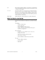
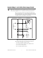
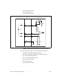
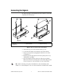
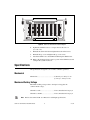
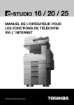
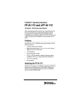
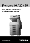
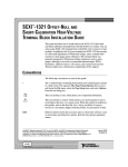
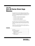
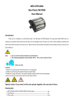
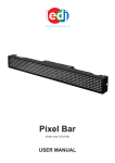
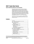
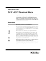
INSTALLATION GUIDE
SCXI -1317 Terminal Block
™
This guide describes how to install and use the SCXI-1317 terminal block
with the SCXI-1521/B quarter-bridge strain-gauge module.
Using the SCXI-1317 terminal block with the SCXI-1521/B module
enables you to conveniently connect quarter-bridge strain gauges. For a
complete description of the use and operation of the SCXI-1521/B module,
refer to the SCXI-1521/B User Manual.
Conventions
The following conventions are used in this manual:
»
The » symbol leads you through nested menu items and dialog box options
to a final action. The sequence File»Page Setup»Options directs you to
pull down the File menu, select the Page Setup item, and select Options
from the last dialog box.
This icon denotes a note, which alerts you to important information.
This icon denotes a caution, which advises you of precautions to take
to avoid injury, data loss, or a system crash. When this icon is marked
on the product, refer to the Read Me First: Safety and Radio-Frequency
Interference document, shipped with the product, for precautions to take.
When symbol is marked on a product it denotes a warning advising you to
take precautions to avoid electrical shock.
When symbol is marked on a product it denotes a component that may be
hot. Touching this component may result in bodily injury.
bold
Bold text denotes items that you must select or click in the software, such
as menu items and dialog box options. Bold text also denotes parameter
names.
italic
Italic text denotes variables, emphasis, a cross reference, or an introduction
to a key concept. This font also denotes text that is a placeholder for a word
or value that you must supply.
monospace
Text in this font denotes text or characters that you should enter from the
keyboard, sections of code, programming examples, and syntax examples.
This font is also used for the proper names of disk drives, paths, directories,
programs, subprograms, subroutines, device names, functions, operations,
variables, filenames, and extensions.
SCXI-1521/B
SCXI-1521/B refers to either the SCXI-1521 or SCXI-1521B module.
What You Need to Get Started
To install and use the SCXI-1317 terminal block, you need the following
items:
❑ Hardware
–
SCXI-1317 terminal block
–
SCXI-1521/B module
–
SCXI or PXI/SCXI combination chassis
–
Cabling, cable adapter, and quarter-bridge strain gauges as
required for your application
❑ Documentation
–
Read Me First: Safety and Radio-Frequency Interference
–
SCXI Quick Start Guide
–
SCXI-1317 Terminal Block Installation Guide
–
SCXI-1521/B User Manual
–
SCXI or PXI/SCXI combination chassis user manual
❑ Tools
–
Number 2 Phillips screwdriver
–
Long-nose pliers
–
Wire cutter
SCXI-1317 Terminal Block Installation Guide
2
ni.com
Quarter-Bridge 2- and 3-Wire Strain-Gauge Circuits
Note Refer to the Read Me First: Safety and Radio-Frequency Interference document
before removing equipment covers or connecting or disconnecting any signal wires.
This section provides information about making quarter-bridge signal
connections using either a 2- or 3-wire strain gauge. Figures 1 and 2 show
the circuit wiring diagrams. If the transducer is shielded, connect the shield
to the GND connection on the SCXI-1317 terminal block.
2-Wire Transducer
SCXI-1317
SCXI-1521/B
+
–
+
RL
–
Ex+
VEX
R1
R4 (gauge)
R2
–
AI
+
RL
VAI
QTR
GND
R3 (QTR)
RSCAL
Figure 1. Quarter-Bridge Circuit Diagram Using a 2-Wire Strain Gauge
The following symbols apply to the circuit diagram and equations:
•
R1 and R2 are half-bridge completion resistors.
•
R3 is the quarter-bridge completion resistor (dummy resistor).
•
R4 is the active measuring element.
•
RSCAL is the shunt-calibration resistor.
© National Instruments Corporation
3
SCXI-1317 Terminal Block Installation Guide
•
VEX is the excitation voltage.
•
RL is the lead resistance.
•
VAI is the measured voltage.
3-Wire Transducer
SCXI-1317
SCXI-1521/B
+
–
+
RL
–
Ex+
VEX
R1
R4 (gauge)
R2
–
AI
+
RL
VAI
QTR
RL
GND
R3 (QTR)
RSCAL
Figure 2. Quarter-Bridge Circuit Diagram Using a 3-Wire Strain Gauge
The following symbols apply to the circuit diagram and equations:
•
R1 and R2 are half-bridge completion resistors.
•
R3 is the quarter-bridge completion resistor (dummy resistor).
•
R4 is the active measuring element.
•
RSCAL is the shunt-calibration resistor.
•
VEX is the excitation voltage.
•
RL is the lead resistance.
•
VAI is the measured voltage.
SCXI-1317 Terminal Block Installation Guide
4
ni.com
Connecting the Signals
To connect the signal to the terminal block, refer to Figures 3 and 4 while
completing the following steps.
6
1
2
7
5
4
3
1
2
3
Top Cover Screws
Top Cover
Thumbscrew
4
5
Connector
Strain-Relief Bar
6
7
Strain-Relief Screws
Safety-Ground Lug
Figure 3. SCXI-1317 Enclosure Parts Locator Diagram
1.
Unscrew the top cover screws and remove the top cover.
2.
Loosen the strain-relief screws and remove the strain-relief bar.
3.
Prepare your signal wire by stripping the insulation no more than
7 mm (0.28 in.).
4.
Run the signal wires through the strain-relief opening. If necessary,
add insulation or padding.
5.
Insert the stripped end of the signal wires fully into the terminal.
Make sure no bare wire extends past the screw terminal. Exposed wire
increases the risk of a short circuit that can cause circuit failure.
When connecting your signals to the SCXI-1317, follow the labeling on the
SCXI-1317, as shown in Figure 4. You can connect the shield of a shielded cable to GND.
Note
© National Instruments Corporation
5
SCXI-1317 Terminal Block Installation Guide
R1
R3
R2
J1
RPJ
QTR
QTR
J8
EX+
QTR
J9
CH21
QTR
J7
EX+
CH18
QTR
EX+
CH15
QTR
J6
EX+
EX+
CH12
QTR
J5
EX+
CH3
CH0
QTR
J4
EX+
CH9
J3
EX+
CH6
J2
EX+
QTR
GND
GND
EX+
EX+
EX+
QTR
QTR
QTR
QTR
QTR
AI
QTR
AI
AI
QTR
AI
AI
QTR
AI
CH22
GND
EX+
AI
CH19
GND
EX+
CH16
GND
EX+
CH13
AI
GND
EX+
CH10
AI
GND
EX+
CH7
AI
GND
EX+
CH4
AI
GND
CH1
AI
AI
QTR
AI
GND
GND
GND
GND
EX+
EX+
EX+
EX+
EX+
EX+
EX+
EX+
EX+
QTR
QTR
AI
AI
QTR
AI
QTR
AI
QTR
AI
QTR
AI
QTR
AI
QTR
AI
CH23
GND
CH20
GND
CH17
GND
CH14
GND
CH11
GND
CH8
AI
CH5
AI
CH2
AI
AI
QTR
AI
SCXI-1317
QUARTER–BRIDGE STRAIN
S/N
UJ
ASSY191141A-01
Figure 4. SCXI-1317 Circuit Parts Location Diagram
6.
Tighten the terminal screws to a torque of 0.57 to 0.79 N ⋅ m
(5 to 7 lb - in.).
7.
Reinstall the strain-relief bar and tighten the strain-relief screws.
8.
Reinstall the top cover and tighten the top cover screws.
9.
Attach the SCXI-1317 to the SCXI-1521/B using the thumbscrews.
10. Refer to the SCXI Quick Start Guide to power on the SCXI chassis and
configure the system in software.
Specifications
All specifications are typical at 25 °C unless otherwise specified.
Mechanical
Dimensions .............................................15.0 cm by 7.9 cm by 3.1 cm
(5.9 in. by 3.1 in. by 1.2 in.)
Maximum Working Voltage
Maximum working voltage refers to the signal voltage plus the
common-mode voltage.
Channel-to-earth .....................................42 Vrms, Installation Category I
Channel-to-channel.................................42 Vrms, Installation Category I
Note
Refer to the SCXI-1521/B User Manual for valid input specifications.
SCXI-1317 Terminal Block Installation Guide
6
ni.com
Environmental
Operating temperature............................ 0 to 50 °C
Storage temperature ............................... –20 to 70 °C
Humidity ................................................ 10 to 90% RH, noncondensing
Maximum altitude .................................. 2,000 m
Pollution Degree (indoor use only) ........ 2
Safety
The SCXI-1317 terminal block meets the requirements of the following
standards for safety and electrical equipment for measurement, control,
and laboratory use:
•
IEC 61010-1, EN 61010-1
•
UL 61010-1
•
CAN/CSA C22.2 No. 61010.1
Note For UL and other safety certifications, refer to the product label, or visit
ni.com/certification, search by model number or product line, and click the
appropriate link in the Certification column.
Electromagnetic Compatibility
Emissions ............................................... EN 55011 Class A at 10 m
FCC Part 15A above 1 GHz
Immunity................................................ EN 61326-1:1997 + A2:2001,
Table 1
EMC/EMI............................................... CE, C-Tick, and FCC Part 15
(Class A) Compliant
Note
For EMC compliance, operate this device with shielded cabling.
© National Instruments Corporation
7
SCXI-1317 Terminal Block Installation Guide
CE Compliance
The SCXI-1317 terminal block meets the essential requirements of
applicable European Directives, as amended for CE marking, as follows:
Low-Voltage Directive (safety)..............73/23/EEC
Electromagnetic Compatibility
Directive (EMC) .....................................89/336/EEC
Refer to the Declaration of Conformity (DoC) for this product for any additional
regulatory compliance information. To obtain the DoC for this product, visit
ni.com/certification, search by model number or product line, and click the
appropriate link in the Certification column.
Note
National Instruments™, NI™, ni.com™, and SCXI™ are trademarks of National Instruments
Corporation. Product and company names mentioned herein are trademarks or trade names of their
respective companies. For patents covering National Instruments products, refer to the appropriate
location: Help»Patents in your software, the patents.txt file on your CD, or ni.com/patents.
© 2004 National Instruments Corp. All rights reserved.
*373794B-01*
373794B-01
Jul04