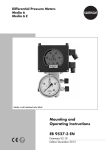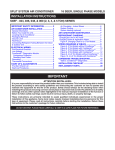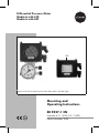
1
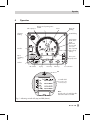
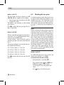
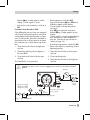
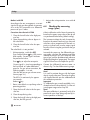
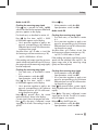
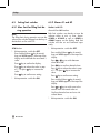
Differential Pressure Meter
Media 6 with LCD
Media 6 with LED
LED
Media 6 with LCD and attached valve block (left), Media 6 with LED (right)
Mounting and
Operating Instructions
EB 9527-1 EN
Firmware A 2.11 (LCD), B 2.11 (LED)
Edition November 2005
Contents
Contents
1
1.1
Design and principle of operation . . . . . . . . . . . . . . . . . . . 6
Technical data . . . . . . . . . . . . . . . . . . . . . . . . . . . . . 8
2
2.1
2.1.1
2.1.2
2.1.3
2.2
Installation . . . . . . . . .
Instrument set-up . . . . . .
Media 6 Indicating Unit . . .
Valve block . . . . . . . . .
Shut-off and equalizing valves
Accessories for connections .
3
Electrical connection . . . . . . . . . . . . . . . . . . . . . . . . . 12
4
4.1
4.1.1
Operation . . . . . . . . . . . . . . . . . . . . . . . . . . . . . . 15
Display and operating elements . . . . . . . . . . . . . . . . . . . . 16
Changing over display mode for Media 6 with LCD. . . . . . . . . . . 16
5
Start-up . . . . . . . . . . . . . . . . . . . . . . . . . . . . . . . 17
6
6.1
6.2
6.3
6.4
6.5
6.5.1
6.5.2
6.6
Settings. . . . . . . . . . . . . . . . .
Write protection. . . . . . . . . . . . .
Selecting the gas type . . . . . . . . . .
Checking the zero point . . . . . . . . .
Checking the measuring range (span) . .
Setting limit switches. . . . . . . . . . .
Max. limit for filling limit during operation
Alarms A1 and A2 . . . . . . . . . . .
Ammeter function . . . . . . . . . . . .
7
7.1
7.2
Memory pen . . . . . . . . . . . . . . . . . . . . . . . . . . . . . 25
Data transfer using memory pen . . . . . . . . . . . . . . . . . . . . 25
Connection to the PC . . . . . . . . . . . . . . . . . . . . . . . . . 27
8
Troubleshooting . . . . . . . . . . . . . . . . . . . . . . . . . . . 27
9
Servicing explosion-protected versions . . . . . . . . . . . . . . . . 29
10
Dimensions in mm . . . . . . . . . . . . . . . . . . . . . . . . . . 30
.
.
.
.
.
.
.
.
.
.
.
.
.
.
.
.
.
.
.
.
.
.
.
.
.
.
.
.
.
.
.
.
.
.
.
.
.
.
.
.
.
.
.
.
.
.
.
.
.
.
.
.
.
.
.
.
.
.
.
.
.
.
.
.
.
.
.
.
.
.
.
.
.
.
.
.
.
.
.
.
.
.
.
.
.
.
.
.
.
.
.
.
.
.
.
.
.
.
.
.
.
.
.
.
.
.
.
.
.
.
.
.
.
.
.
.
.
.
.
.
.
.
.
.
.
.
.
.
.
.
.
.
.
.
.
.
.
.
.
.
.
.
.
.
.
.
.
.
.
.
.
.
.
.
.
.
.
.
.
.
.
.
.
.
.
.
.
.
.
.
.
.
.
.
.
.
.
.
.
.
.
.
.
.
.
.
.
.
.
.
.
.
.
.
.
.
.
.
.
.
.
.
.
.
.
.
.
.
.
.
.
.
.
.
.
.
.
.
.
.
.
.
.
.
.
.
.
.
.
.
.
.
.
.
.
.
.
.
.
.
.
.
.
.
.
.
.
.
.
.
.
.
.
.
.
.
.
.
.
.
.
10
10
10
10
10
11
17
17
17
18
20
22
22
22
24
Test certificate . . . . . . . . . . . . . . . . . . . . . . . . . . . . 31
2
EB 9527-1 EN
Safety instructions
Safety instructions
4 Assembly, commissioning and operation of the device may only be
4
4
4
performed by trained and experienced personnel familiar with this
product.
According to these mounting and operating instructions, trained
personnel is referred to persons who are able to judge the work they are
assigned to and recognize possible dangers due to their specialized
training, their knowledge and experience as well as their knowledge of the
relevant standards.
Explosion-protected versions of this device may only be operated by
personnel who have undergone special training or instructions or who are
authorized to work on explosion-protected devices in hazardous areas.
See section 9 for more details.
Any hazards which could be caused by the process medium and the
operating pressure in the instrument are to be prevented by means of
appropriate measures.
Make sure that the instrument is only used where temperatures and
operating pressure do not exceed the sizing data specified in the order.
The Media 6 Differential Pressure Meter is not certified for measuring
flammable gases or liquids in Zone 0 areas.
Proper shipping and appropriate storage are assumed.
Note! Devices with the CE mark meet the requirements specified in the
Directive 94/9/EC and the Directive 89/336/EEC.
The Declaration of Conformity is available on request.
EB 9527-1 EN
3
Firmware modification
Table 1 · Device firmware versions
Modifications in device firmware compared to the previous version
Previous version
New version
A 2.03/B 2.03
A 2.10/B 2.10
Limit switches
The limit switches A1 and A2 are configured over software as minimum
and maximum alarms. They can be adjusted separately over the keys on
the device.
Filling limit during
operation
The filling limit during operation UCW can be set over the keys on the
device independently of the limit switches.
A 2.10/B 2.10
A 2.11/B 2.11
Error code
The current output of the Media 6 device is switched to ≤ 3.6 mA.
4
EB 9527-1 EN
Firmware modification
Modifications in device firmware compared to the previous version
Previous version
New version
EB 9527-1 EN
5
Design and principle of operation
1
Design and
operation
principle
of The user-specific data are saved in the
EEPROM (4). Data can also be saved in this
manner and kept until they are overwritten
The Media 6 Differential Pressure Meters mea- again. The operating data of Media 6 can
sure and indicate the differential pressure or also be uploaded to the memory pen and
measured variables derived from the differen- downloaded to the device on site.
tial pressure. They are designed for gases and
liquids, for example, for liquid level measure- The memory pen can be configured on a PC
with the corresponding TROVIS-VIEW softment in pressurized vessels.
ware, using the operating data, e.g. type of
The measuring device consists of a dp cell and gas, gas density, tank design and position of
an indicating unit. The cell has a measuring the limit switches. The data are used to convert
diaphragm and range springs designed for a the differential pressure into a value proporcertain measuring span, and the indicating tional to the tank contents then used to display
unit is equipped with either an LCD (liquid and issue the direct current signal from 4 to
crystal display) or an LED (light-emitting di- 20 mA.
ode) to indicate important operating condiFour types of gas and various write protection
tions.
functions for stored data can be selected using
The differential pressure Δp = p1 – p2 acts on the DIL switches (6).
the measuring diaphragm (1.1) which is counterbalanced by the range springs (1.2). The Several operating functions (zero and span
movement made by the measuring diaphragm adjustment, filling limit during operation, limit
and lever (1.3) which is proportional to the dif- switches and test function settings, etc.) as well
ferential pressure is led by the elastic disc (1.4) as operating states (load/save operating valout of the pressure chamber and converted by ues) can be set using three keys (5).
the displacement sensor (2) into an electric
signal.
This signal is compared with the data stored in
the EEPROM (4) and processed in the microprocessor (3) which controls both the display
(7, LCD or LED) and the D/A converter (9) for
the output signal which is issued at connector
A as a two-wire 4 to 20 mA transmitter signal.
The SERIAL INTERFACE (10) enables the device to be configured using a special memory
pen or a connecting cable and a PC which has
SAMSON's TROVIS-VIEW Configuration and
Operator Interface installed.
6
EB 9527-1 EN
Design and principle of operation
Indicating unit with LCD or LED
Connection A
UB = 12 V to 36 V DC
IA = 4 to 20 mA
Min./max. alarm A1
Connection B
Min./max. alarm A2
SERIAL INTERFACE
µP
EEPROM
1
Differential pressure cell
1.1 Measuring diaphragm
dp cell
1.2 Range springs
1.3 Lever
1.4 Elastic disc
1.5 Diaphragm axis
Valve block
with
pressure
gauge
2
Displacement sensor
3
Microprocessor
4
Memory
5
Keys
6
DIL switch
7
Indicating unit with LCD
or LED
8
Limit switch
9
D/A converter
10 SERIAL INTERFACE
Fig. 1 · Functional diagram
EB 9527-1 EN
7
Technical data
1.1
Technical data
Table 2 · Technical data
Differential pressure meter
Measuring range
mbar
0 to
100
0 to
160
0 to
250
0 to
400
0 to
600
0 to
10001)
0 to
16001)
0 to
25001)
0 to
36001)
≤ 250
≥ 125
≤ 400
≥ 100
≤ 600
≥ 150
≤ 1000
≥ 1250
≤ 1600
≥ 1400
≤ 2500
≥ 1500
≤ 3600
≥ 1500
<125
≥ 50
<100
≥ 80
<150
≥ 120
<250
≥ 200
Adjustable measuring span in mbar
Class ±1.0%
from
to
Class ±1.6%
from
to
≤100
≥ 60
<160
≥ 60
Class ±2.5%
from
to
<60
≥ 35 2)
<60
≥ 32
Nominal pressure
PN 50, overloadable on one side up to 50 bar
Display
LCD Ø 90 or LED Ø 3
Performance
Deviation from terminal-based
linearity
Output and reading linear to the tank contents
< ±1.0 % or < ±2.5 % (including hysteresis) depending on the span selected
< 0.25 % or < ±0.5 % depending on the span selected
Sensitivity
Static pressure effect
< 0.03 % / 1 bar
Influence of ambient temperature in the range between
–20 to +70 °C
On zero point
On span
Limit switches
< ±0.2 %/10 K
< ±0.2 %/10 K
Two software contacts A1 and A2, configurable as minimum or maximum alarms
according to EN 60947-5-6
Control circuit,
adjustable in 1 % steps
Hysteresis
Range of inversion, approx.
Weight
Rating according to connected switching amplifier according to
EN 60947-5-6, e.g. KFA6- SR2- Ex2.W or KFA-SR2- Ex1.W
1 % based on maximum tank capacity (MCN)
< 0.6 %
Approx. 3 kg without valve block · Approx. 5 kg with valve block
1) A class accuracy of 0.6 % can be expected for measuring ranges 1000, 1600, 2500 and 3600 mbar with spans
≤ 100 % to ≥ 50 % of the nominal range.
2) The class accuracy of Class 2.5 may not be reached in cases where the span does not fall within this specified span.
Note!
All pressures stated as gauge pressures · All errors and deviations stated in % of the adjusted span.
The Media 6 Differential Pressure Meter is not certified for measuring flammable gases or liquids in Zone 0 areas.
8
EB 9527-1 EN
Technical data
Version
5006-0
5006-1
Output
4 to 20 mA
Permissible load RB in ohm
RB =
UB – 12 V
0.020 A
Output current circuit
–
Intrinsically safe (Media 6 with LCD
and LED) · Refer to
PTB 00 ATEX 2074 in appendix
Supply voltage UB
two-wire transmitter
12 to 36 V
12 to 28 V DC only in combination
with an intrinsically safe circuit
–40 to +70 °C
T6 max. +60 °C
T5 max. +70 °C
Permissible ambient temperature
Permissible storage temperature
Degree of protection
–40 to +80 °C
IP 65 according to DIN VDE 0470 and EN 60529
Materials
Version
Standard version
Housing
CW617N (brass) or CrNi steel
Measuring diaphragm and seals
ECO (others on request)
Range springs
Diaphragm plates and functioning
parts
CrNi steel
Lever
Indicating unit
Polycarbonate, polyamide
Note!
Devices intended for oxygen service are labeled
“Oxygen! Keep free of oil and grease!"
These versions are cleaned and assembled by the manufacturer under special conditions.
Appropriate gloves need to be worn on replacing parts that come into contact with oxygen, e.g.
measuring springs.
When returning devices designed for oxygen service to the manufacturer for repair, the sender
assumes full responsibility that the handling of the devices to be repaired meets the requirements specified in VBG 62 or equivalent regulations until the devices are handed over to the
manufacturer. Otherwise, SAMSON AG will not accept any responsibility.
EB 9527-1 EN
9
Installation
2
Installation
4 Clean
4
4
Fig. 2 · Set-up for liquid level measurement.
The example shows the standard set-up in a
cryogenic application.
2.1
Instrument set-up
the connections carefully prior to
connecting the measuring lines. Do not
clean the instrument using compressed air
or pressurized water.
Secure the instrument at the place of installation to a pipe, wall or mounting plate
free of vibration.
For attachment to vertical or horizontal
pipes, use a mounting component with
clamp. For wall mounting, use a mounting
component without clamp. See the dimensional drawing on page 30 for mounting
in control panels.
Note!
We recommend installing one shut-off valve in
each measuring line and, additionally, an
equalizing valve, or a SAMSON valve block
as a compact assembly to shut off both measuring lines.
Additionally, the zero point can be checked at
the indicating unit by bypassing the circuit.
2.1.2 Valve block
The three valves combined in a valve block
with test and pressure gauge connections
Make sure that the high-pressure line is con- (Fig. 3), which are flanged directly onto the
nected to the high-pressure connection and bottom of the dp cell, are available as
the low-pressure line to the low-pressure con- accessories.
nection.
2.1.1 Media 6 Indicating Unit
2.1.3 Shut-off and equalizing valves
Note!
Special fittings are required to connect measuring lines. In addition, depending on the instrument set-up, connections left unused must
be fitted with plugs or vent plugs (see section 2.2 on accessories for more details).
10
EB 9527-1 EN
As an alternative to the SAMSON valve block,
both shut-off valves as well as the bypass
valve/equalizing valve can also be installed
as shown in Fig. 3.1.
Installation
2.2
Accessories for connections
dium (especially when measuring gases) must
be ordered separately.
Open product connections are protected
The screw fittings and SAMSON valve blocks
against contamination by NBR plugs.
are listed together with their order numbers in
Required screw fittings, sealing or vent plugs the Data Sheet T 9555 EN.
and screw joints with restrictions used to
dampen vibrations caused by the process me-
Liquid level measurement
Media 6
Flow rate
measurement
From the point of
measurement
Test connection
Equalizing valve
(lead-sealable)
Bore hole for
sealing wire
To indicating unit
Shut-off valve (+)
Shut-off valve (–)
1
Shut-off valve
2
Equalizing valve
Pressure gauge connection
Connection for measuring lines
Fig. 3 · SAMSON valve block
Fig. 3.1 · Shut-off valves and
equalizing valves, separate or
combined in a block (schematics)
EB 9527-1 EN
11
Electrical connection
3
Electrical connection
4 As far as the electrical installation of the device is concerned, the relevant
4
4
4
4
national regulations governing the installation of electrical equipment and
the national accident prevention regulations of the country of destination
must be adhered to. In Germany, these are the VDE regulations and
accident prevention regulations of the employer's liability insurance.
For assembly and installation in hazardous areas, the following standards
apply: EN 60079-14: 1997 (VDE 0165 Part 1/8.98) "Electrical
apparatus for explosive gas areas" and EN 50281-1-2: (VDE 0165
Part 2) 11.99 "Electrical apparatus for use in the presence of combustible
dust."
For intrinsically safe electrical apparatus that are certified according to the
Directive 79/196/EEC, the data specified in the certificate of conformity
apply for connection of intrinsically safe circuits.
For intrinsically safe electrical apparatus that are certified according to the
Directive 94/9/EC, the data specified in the EC type examination
certificate apply for connection of intrinsically safe circuits.
Note: It is absolutely necessary to keep to the terminal plan specified in the
certificate. Reversal of the electrical connections may cause the explosion
protection to be ineffective!
Do not tamper with screws inside or on the case which have been sealed
with paint.
Note on the selection of cables and wires:
To run several intrinsically safe circuits in a multi-core cable, read paragraph 12 of
EN 60079-14 (VDE 0165/8.98). For generally used insulating materials, for example polyethylene, the radial thickness of the conductor insulation has to be at least 0.2 mm. The diameter of
a single wire in a flexible conductor shall not be smaller than 0.1 mm. The conductor ends are to
be protected from unlaying, e.g. by using wire end ferrules.
12
EB 9527-1 EN
Electrical connection
Connector A
Test connection
Two-wire connection for 4 to 20 mA signal,
perm. load RB.=
UB – 12 V
in ohm
RB =
0.020 A
An ammeter can be connected to the test terminals + and – for checking the output signal
on calibration. The output signal of the
two-wire circuit is not interrupted.
Make sure that there is a load of < 0.4 V DC at
the ammeter for the test connection.
The supply voltage is usually 24 V DC. It may
be between at least 12 and maximum
36 V DC while considering the supply lead's Caution!
resistance directly at the connecting terminals If the cable socket is removed from the connector, the degree of protection IP 65 becomes inof the connector.
effective!
Protect the connector from moisture during inConnector B
stallation work and transport by keeping the
Connection for two software limit switches in cable socket part screwed on and sealed!
type of protection "Intrinsic Safety" EEx ia IIC
for control circuits conforming with NAMUR to
switching amplifiers as per EN 60947-5-6.
Maximum values:
Ui = 20 V, Ii = 60 mA, Pi = 250 mW
Ci = 5.3 nF, Li = negligible
Power supply unit
Connection A · Two-wire connection
for standardized 4 to 20 mA signal
Cable socket
Order no: 8831-0503
Network
Connector connections for cable
Ø 8 to 10 mm
Limit switches with switching amplifier
Min./max. A1
Connection B · Software limit
switches
Cable socket
Order no.: 8831-0500
Min./max. A2
Fig. 4 · Terminal assignment of DIN 43650 connector, form A
EB 9527-1 EN
13
Electrical connection
Table 3 · Summary of functions of both software limit switches A1 and A2
at connector B
Proximity switch
for ...
Alarm contact
Gas tapping/Tank filling
(1 min./1 max. alarm)
A1
A2
Gas tapping
(2 min. alarm)
A1
A2
Tank filling (2 max. alarms)
A1
Value falls below
High resistance Low resistance High resistance High resistance Low resistance
limit
Value exceeds
limit
Low resistance High resistance Low resistance
A2
Low resistance
Low resistance High resistance High resistance
Both limit switches A1/A2 can be configured separately to function as maximum or minimum alarms.
Contact assumes low resistance
Switching signal “ON” · Function: Contact closed or output effectively conducting,
power consumption ≥ 3 mA
Contact assumes high resistance
Switching signal “OFF” · Function: Contact open or output effectively non-conducting,
power consumption ≤ 1 mA
14
EB 9527-1 EN
Operation
4
Operation
Tank capacity %
Gas type and operating status
Tank ID
Factor
Alarm A2
blinking
Alarm A1
blinking
UCW blinking
Tank capacity
MCN, SCN,
UCW,
differential
pressure and
error code
Interface
Unit of quantity
tank capacity
and Δp
Open
equalizing
valve
Nom. perm.
capacity SCN
Tank ID
DIL switches
Up key
Down key
Enter key
Test connection
LED
Insertable label
for gas types and
measuring ranges
Note!
A quick guide is located behind the
label of the Media 6 with LED.
Fig. 5 · Indicating unit with LCD (top) and LED (bottom)
EB 9527-1 EN
15
Operation
4.1
Display and operating
elements
All the necessary information and measured
data stored in the instrument's memory are
shown on the display of Media 6 with LCD.
Although the Media 6 with LED version does
not have such a digital display, important operating conditions are indicated by the LED.
Three keys are used to operate the differential
pressure meter:
MCN/R
100 % capacity assigned to
20 mA signal
SCN
Save capacity nominal
geometric capacity up to overflow/
gauge pipe
SCN/R
100 % capacity assigned to
20 mA signal
UCW
Useable capacity work
Δ P100
Maximum differential pressure
PTANK
Nominal tank pressure
Indicated value corresponds to the
pressure assigned to the density
(liquid) according to vapor pressure
diagram.
If the calculations for MCN and SCN
are based on density at 1 bar, then
1 bar is shown for PTANK.
X-TANK16
e.g. tank ID as running text
ERROR
Error message displayed
automatically when an error occurs
(see section 8 on troubleshooting)
OFF
Special signal on opening the
equalizing valve, I = 3.6 mA (refer
to section 4.1 of EB 9527-2 EN).
Up key
Down key
Enter key
and a DIL switch with four switches to select the
type of gas and write protection function.
4.1.1 Changing over display mode
for Media 6 with LCD
Press the key to change over from the standard display to seven other display modes.
After 8 seconds or after the message has finished running across the display, the display
returns automatically to the standard display.
O2
e.g. gas name and current tank
ΔP
current differential pressure
MCN
Max. capacity nominal
max. tank capacity
16
EB 9527-1 EN
Start-up
5
Start-up
1. Open the equalizing valve.
2. Slowly open the high-pressure line.
6
Settings
6.1
Write protection
3. Close the equalizing valve or the bypass
of the valve block.
The instrument has two write protection functions:
4. Open the low-pressure line.
WRITE PROTECTION to prevent the operating
data from being changed unintentionally.
SPAN PROTECTION as an additional write
Note!
Check the zero point at the dp cell, if neces- protection for the span setting.
sary, as described in section 6.3, and restart
The write protection at switch 4 of the DIL
the instrument.
switch must first be switched OFF before various operating functions can be carried out
and switched ON again afterwards.
6.2
Selecting the gas type
The required gas type can be selected using
the positions of switches 1 and 2 according to
the table and diagram below.
Gas 1
1
OFF
2
OFF
Gas 2
Gas 3
1
ON
2
OFF
1
OFF
2
ON
Gas 4
1
ON
2
ON
ON
OFF
1
Gas type
2
3
4
Write protection
Span protection
Fig. 6 · DIL switch with switches 1 to 4
EB 9527-1 EN
17
Settings
Media 6 with LCD
6.3
Checking the zero point
The gas formula of the gas chosen, e.g. AR, On checking the zero point, the pressure must
CO2, O2, N2, etc. appears on the display.
be equal in both measuring chambers at atSelect the gas type according to the table mospheric pressure. Thas means the current
signal at connector A or at the TEST connecusing the DIL switch.
The display is not activated, just the selected tion must be 4 mA when the differential pressure Δp = 0 mbar (see test arrangement in
gas is shown!
Fig. 7.)
Press to confirm the new gas type. The display is reactivated.
Note!
When activating the gas column correction
(refer to section 4.2.2 in EB 9527-2 EN), it is
Media 6 with LED
important to take into account that the gas colThe four selectable gas types are listed down- umns in the measuring lines reduce the differward from 1 to 4 or specified with their desig- ential pressure as they have an opposing effect on each other. At a pressure equilibrium
nation on the insertable label.
of Δp = 0 mbar, the meter readout is negative
Use the switches 1 and 2 of the DIL switch to for the tank capacity and the output signal inselect the gas type, also refer to the table and dicates a value < 4 mA. In this case, readjust
Fig. 6.
the zero point as described in following so that
The gas type selected is indicated by the num- the display indicates 0 % = 0000 when Δp =
0 mbar. The output signal changes, but indiber of times the LED blinks.
cates a value < 4 mA in accordance with the
Gas 1 Pause - Blinks x1 - Pause etc.
gas column correction data.
Gas 2 Pause - Blinks x2 - Pause etc.
4
Gas 3 Pause - Blinks x3 - Pause etc.
Media 6 with LCD
Gas 4 Pause - Blinks x4 - Pause etc.
At a differential pressure of Δp = 0 mbar, the
Press to confirm the new gas type. The LED display must indicate 0 % or 0000.
goes out.
Correction when the tank is empty
4 Write protection: switch 4 to OFF
Press and hold down key. ZERO and
X,0X mbar appear on the display.
Current signal I shows the present mA
value.
Press
18
EB 9527-1 EN
key to adust the zero point.
Settings
Release key, 0 mbar appears on the
display. Current signal I = 4 mA.
4 Write protection: switch 4 to OFF
Press and hold down key. ZERO and
X,X mbar appear on the display.
Current signal I indicates the present
mA value.
Press key to adjust the zero point.
Release key, 0 mbar appears on the
display.
Current signal I = 4 mA corresponding to
the liquid level at 0 mbar differential
pressure. (See note on gas column correction on page 18.)
4 Activate the write protection: switch 4 to
ON.
Correction when the tank is filled
If the differential pressure lines are equipped
with shut-off and equalizing valves, zero point
can be checked even when the plant is in operation. To achieve this, place the valve block or
equalizing valve in the test position to obtain
the same pressure in both measuring chambers.
1. Close the shut-off valve in the high-pressure line.
4 Activate write protection: switch 4 to ON.
4 Return valve block or equalizing valve to
operating position:
2. Open the equalizing valve or bypass in
the valve block.
1. Open the shut-off valve in the low-pressure line.
3. Close the shut-off valve in the low-pressure line.
2. Close equalizing valve.
The valve block is in test position!
3. Open the shut-off valve in the high-pressure line.
Caution! For devices used to measure oxygen, the test medium must be free of oil and
grease!
Ammeter
A
Supply unit
B
Power
supply
Supply air reducing
station with oil filter
and pressure gauge
Test
pressure
Use air free of oil or other
gases, e.g. N2
Precision regulator with pressure gauge Class 0.1
Fig. 7 · Test arrangement
EB 9527-1 EN
19
Settings
Media 6 with LED
According to the test arrangement, a current
signal of 4 mA must be supplied at connector
A or at the TEST connection at a differential
pressure of Δp = 0 mbar.
Correction when the tank is filled
1. Close the shut-off valve in the high-pressure line.
2. Open the equalizing valve or bypass in
the valve block.
3. Close the shut-off valve in the low-pressure line.
The valve block is in test position!
4 Write protection: switch 4 to OFF.
Press and hold down key. LED starts to
blink rapidly. Current signal I indicates
the present mA value.
Press
key to adjust the zero point.
Current signal I = 4 mA corresponding to
the liquid level at 0 mbar differential
pressure. For gas column correction, the
following applies: I < 4 mA.
(See also the note on gas column correction on page 18.)
4 Activate the write protection: turn switch 4
to ON.
6.4
Checking the measuring
range (span)
A basic calibration with a linear characteristic
based on the upper range value of the dp cell
was performed at the factory (default setting).
The instrument adopts the tank characteristic
based on the entered tank and gas data and
calculates values proportional to the tank capacity to indicate and issue the output signal
from 4 to 20 mA using the gas data for the gas
selected.
In exactly the same way, the differential pressure meter calculates the maximum possible
differential pressure Δp 100 in mbar for each
type of gas and the predetermined reference
height (total height or gauge pipe). The output
signal of 20 mA must correspond to Δp100.
Connect the differential pressure meter as
shown in Fig. 7 to check the measuring range.
Note!
It is useful to activate the gas with the largest
density to adjust the span. The values for gases
The LED is lit continuously for approx.
with smaller densities are also calibrated with
two seconds.
this calibration procedure.
Important!
Release key.
To calibrate the gas currently available, its inReturn valve block or equalizing valve to dicated value must be at least 85 % of the adoperating position:
justed upper range value of Δp100.
Note!
1. Open the shut-off valve in the low-presThe span calibration is protected (switch 3) to
sure line.
prevent the span from being adjusted by in2. Close the equalizing valve.
correct operation of the keys.
3. Open the shut-off valve in the high-pressure line, the LED goes off.
4
20
EB 9527-1 EN
Settings
Media 6 with LCD
Release
key.
4
Write protection: switch 4 to ON.
Checking the measuring range (span)
Span protection: switch 3 to ON.
If the
key is pressed five times, Δp100,
which is the value for the maximum differential
Media 6 with LED
pressure, appears on the display.
First check zero, as described in section 6.3.
Checking the measuring range (span)
First check zero, as described in section
Press
key five times. Δp100 = X.XXX 4
6.3.
(x1000) mbar appears on the display.
4 Use a precision regulator to apply a test
4 Use a precision regulator to apply a test pressure corresponding to the maximum
pressure corresponding to the maximum
differential pressure Δp100 while monitordifferential pressure Δp100 while monitoring the pressure gauge.
ing the pressure gauge.
Set point values: Δp = 0 mbar = 4 mA (See
Set point values: Δp = 0 mbar = 4 mA (See also note on gas column correction on p. 18).
also note on gas column correction on p. 18).
Δp100 % = XXXX mbar = 20 mA.
Δp100 = XXXX mbar = 20 mA.
If the reading and output signal do not correIf the reading and output signal do not corre- spond with the indicated value Δp100%, the
spond with the indicated value Δp100, the up- upper range value of the measuring range
per range value of the measuring range (span) (span) must be readjusted.
must be readjusted.
Checking the measuring range (span)
Checking the measuring range (span)
4 First check zero, as described in section 4
Write protection: switch 4 to OFF.
6.3.
Span protection: switch 3 to OFF.
4 Write protection: switch 4 to OFF.
4 Use a precision regulator to apply a test
Span protection: switch 3 to OFF.
Press
key five times. Δp100 = X.XXX
(x1000) mbar appears on the display.
pressure corresponding to the maximum
differential pressure Δp100 while monitoring the pressure gauge.
Use a precision regulator to apply a test Keep
key pressed down, current signal I
pressure corresponding to the maximum shows the present mA value. LED starts to blink
differential pressure Δp 100 while moni- rapidly.
toring the pressure gauge.
Press
key. The span is calibrated, current
Keep
key pressed down, the current
signal goes to 20 mA. The LED is lit continumeasured value is shown in the display.
ously for approx. two seconds.
Current signal I shows the present mA value.
Release key, the LED goes out.
Press
key, the span is calibrated, current
Write protection: switch 4 to ON.
signal goes to 20 mA. The reading is equal to
Span protection: switch 3 to ON.
Δp100.
4
4
EB 9527-1 EN
21
Settings
6.5
Setting limit switches
6.5.1 Max. limit for filling limit during operation
Note!
The filling limit during operation set over the
software can only be changed over the keys in
the Media 6 version with LCD.
UCW Marker
4 Write protection: switch 4 to OFF.
Press and hold down key 8 seconds
long until UCW appears at the top of the
display and underneath the associated %
value.
Press
key to confirm the display.
Press key to reduce the value in steps
of 1 % or press key to increase the
value.
Press
key to confirm new setting.
4 Write protection: switch 4 to ON.
6.5.2 Alarms A1 and A2
Media 6 with LCD
Alarm A1 and A2 markers
Both limit switches are already set over the
software either as min. or max. alarms.
A1MIN or A1MAX as well as A2MIN or
A2MAX appear on the display. Both limit
switches must be set and confirmed separately.
4 Write protection: switch 4 to OFF.
Press and hold down key 8 seconds
long until UCW appears at the top of the
display.
Press or key to switch between
alarm A1 or A2.
Press
key to confirm selected alarm.
Press key to reduce the value in steps
of 1 % or press key to increase the
value.
Press
key to confirm new setting.
Press and hold down key 8 seconds
long until UCW appears at the top of the
display.
Press or key to switch over to the
second alarm that needs to be set.
Confirm selected alarm and set as described above.
4 Write protection: switch 4 to ON.
22
EB 9527-1 EN
Settings
Media 6 with LED
Connect an ammeter to the power supply at
connector A (Fig. 7) or to the TEST terminal.
Both limit switches are already set over the
software as either min. alarm or max. alarms
and are displayed to the assigned differential
pressure corresponding to a current between
4 and 20 mA. Both alarms need to be set and
confirmed separately.
Press key to reduce the value in steps
of 1 % or press key to increase the
value.
Press key to confirm new setting. The
LED goes off.
4 Write protection: switch 4 to OFF.
4 Write protection: switch 4 to OFF.
Alarm A1
Press and hold down key 8 seconds
long until the LED starts to blink slowly.
Press key to display the currently set
A1 alarm at the ammeter. The LED lights
up.
Press key to reduce the value in steps
of 1 % or press key to increase the
value.
Press key to confirm new setting. The
LED goes off.
Alarm A2
Press and hold down key 8 seconds
long until the LED starts to blink slowly.
Press or key to switch to the A2
alarm, indicated by the LED which starts
to blink quickly.
Press key to confirm the selected
alarm. The LED lights up.
The currently set A2 alarm is indicated
at the ammeter.
EB 9527-1 EN
23
Settings
6.6
Ammeter function
Media 6 with LED
4
Write protection: switch 4 to OFF.
In order to check the functioning of connected
devices, an output signal of 4 to 20 or
22.8 mA can be adjusted for a short time re- Ammeter 4 mA
gardless of the current liquid level in the tank.
Press and hold down key.
Media 6 with LCD
4 Write protection: switch 4 to OFF.
Ammeter 4 mA
Press and hold down
key.
Press key within 8 seconds and hold
down, output signal I = 4.0 mA.
Release key to change the signal between 4.0 mA and 22.8 mA.
Release key, current signal I indicates
the mA value corresponding to the tank
capacity.
20 mA ammeter
Press and hold down
key.
Press key within 8 seconds and hold
down, output signal I = 20.0 mA.
Release key to change the signal between 20.0 mA and 22.8 mA.
Release key, current signal I indicates
the mA value corresponding to the tank
capacity.
4 Write protection: switch 4 to ON.
24
EB 9527-1 EN
Press key within 8 seconds and hold
down, output signal I = 4.0 mA indicated
by the LED blinking quickly.
Press key to change the signal between 4.0 mA and 22.8 mA indicated by
an illuminated LED.
Release key, current signal I indicates
the mA value corresponding to the tank
capacity. The LED goes out.
Ammeter 20 mA
Press and hold down
key.
Press key within 8 seconds and hold
down, output signal I = 20.0 mA indicated by the LED blinking slowly.
Press key to change the signal between 20.0 mA and 22.8 mA indicated
by an illuminated LED.
Release key, current signal I indicates
the mA value corresponding to the tank
capacity. The LED goes out.
4 Write protection: switch 4 to ON.
Memory pen
7
Memory pen
7.1
Data transfer using memory
pen
The memory pen is a portable data carrier. It
transfers standardized data which corresponds with the type of tank and the relevant
gas data to Media 6 instruments on site over
the RS-232 interface (SERIAL INTERFACE),
without requiring a PC or a notebook to be
connected.
Note!
Memory pens with data sets or existing configurations which were created with earlier
TROVIS-VIEW software versions (1.02 to
2.20) are not 1:1 compatible with Media 6
devices with firmware versions A 2.10 or
B 2.10.
They must first be loaded and converted over
TROVIS-VIEW software version (2.30 or
higher).
Memory pens must be configured to suit the
Media 6 firmware version.
A label tag can be attached to the memory
Media 6 with LCD
pen for identification.
The customized data is transferred to the mem- Data transfer from Media 6 to memory pen
ory pen from a PC/notebook using the (upload) and from memory pen to Media 6
TROVIS-VIEW Configuration and Operator (download). Status: Write and read
Interface (see EB 9527-2 EN) or the data can
Insert memory pen into the SERIAL
be copied from another Media 6 instrument.
INTERFACE jack.
The memory pen can be configured to write MEMWR appears at the top of the display.
and read, read only or write only depending
Press or key to switch between
on the status determined by TROVIS-VIEW,
MEMWR = Write data from Media 6 desee table below:
vice to the memory pen and
4
MEMRD = Read data from the
memory pen to the Media 6 device.
Table 4 · Memory pen status
Memory pen
status
With LCD
LED indicated by
blinking sequence
Procedure
Write
and
read
MEMWR
or
MEMRD
Long blinking
= writing
Short blinking
= reading
Read only
MEMRD
Short blinking
Read data from the memory pen to the Media 6
device.
Write only
MEMWR
Long blinking
Write data from Media 6 device to the memory
pen.
Write data from Media 6 to the memory pen or
read data from the Media 6 device to the
memory pen.
EB 9527-1 EN
25
Memory pen
4 MEMRD write protection: switch 4 to OFF.
Press
key to activate selection.
RUN appears on the display. When the
data are saved, DONE appears on the
display. You can remove the memory
pen.
4 MEMRD write protection: switch 4 to ON.
Transfer data from memory pen to the Media 6 device
Status: Read only
4 Write protection: switch 4 to OFF.
4 Insert memory pen into the
SERIAL
INTERFACE jack.
MEMRD appears at the top of the display.
Press
key to start the data transfer.
RUN appears on the display. When the
data are saved in the Media 6 device,
DONE appears on the display. You can
remove the memory pen.
4 Write protection: switch 4 to ON.
Transfer data from the Media 6 device to
the memory pen
Status: Write only
4 Insert
memory pen into the SERIAL
INTERFACE jack.
MEMWR appears at the top of the display.
Press
key to start the data transfer.
RUN appears on the display. When the
data are saved in the memory pen,
DONE appears on the display. You can
remove the memory pen.
26
EB 9527-1 EN
Media 6 with LED
Transfer data from the Media 6 device to
the memory pen or from the memory pen to
the Media 6 device
Status: Write and read
Insert memory pen into the SERIAL
INTERFACE jack.
The LED blinks in short sequence to indicate
that data are being read from the memory pen
and blinks in a slow sequence to indicate that
data are being written to the memory pen.
4
Press or key to switch between
writing data from the Media 6 device to
the memory pen and reading data from
the memory pen to the Media 6 device.
4 On selecting read from the memory pen:
write protection, switch 4 to OFF.
Press key to activate selection. The LED
illuminates
4 Remove the memory pen when the
goes off.
4 Write protection: switch 4 to ON.
LED
Transfer data from memory pen to the Media 6 device
Status: Read only
4 Write protection: switch 4 to OFF.
4 Insert memory pen into the
SERIAL
INTERFACE jack.
The LED blinks rapidly.
Press key to start the data transfer, the
LED goes on.
4 You can remove the memory pen when the
LED goes off.
4 Write protection: switch 4 to ON.
Troubleshooting
Transfer data from the Media 6 device to
the memory pen
Status: Write only
8
Troubleshooting
Errors that occur appear at the top of the LC
display indicated by the word ERROR with the
Insert the memory pen into the SERIAL corresponding error code, e.g. 16, below it.
INTERFACE jack.
The blinking sequence of the LED indicates the
The LED blinks slowly.
error code of Media 6 with LED. For example,
Press key to start the data transfer, the error code 1 is signaled as follows:
LED goes on.
4
4 You can remove the memory pen when the
LED goes off.
long medium
9x short
Refer to the table for the description of the error codes.
7.2
Connection to the PC
Reset or confirm errors by pressing the key.
Any new error messages then remain suppressed for 8 seconds.
Media 6 can also be operated over the SERIAL
INTERFACE jack from a PC/notebook using Troubleshooting using the memory pen
the TROVIS-VIEW Configuration and Operator Interface.
If you have a SAMSON memory pen, it can be
used, if necessary, to transfer new data to the
Refer to the Mounting and Operating Instrucinstrument within this time.
tions EB 9527-2 EN for operation.
Troubleshooting using a PC or notebook
Communication with a PC or notebook over
the SERIAL INTERFACE jack functions even in
the error mode.
Hardware errors
These errors are saved in the EEPROM and reset over the SERIAL INTERFACE after repair at
the manufacturer's.
EB 9527-1 EN
27
Troubleshooting
Table 5 · Error codes
Error code
Number
on LCD
Description
Remedy
Oscillatory circuit differential inductor faulty
Return device to SAMSON for repair
LED blinking
sequence
Hardware error
1
1x long/medium/
9x short
2
1x long/1x short/ RAM checksum error, RAM is defective
medium/8x short
Return device to SAMSON for repair
4
1x long/2x short/ EEPROM checksum error.
medium/7x short
Return device to SAMSON for repair
Calibration or measuring range error or error in the tank characteristic
8
1x long/3x short/ Δp not within permissible range. The
Reset error and load other tank or
permissible range is between 20 and 110 %
medium/6x short
gas data or use a suitable dp cell.
of the nominal range of dp cell.
16
1x long/4x short/
Error in the tank characteristic
medium/5x short
The coordinates for the tank
characteristic must be strictly
monotonic increasing.
32
Calibration Δp sensor.
1x long/5x short/ Zero and span adjustment produce values
medium/4x short outside of the permissible range. These
values are not saved in the EEPROM.
Check zero and span adjustment,
taking the Δp into account.
Otherwise, return device to
SAMSON for repair
Other errors
64
1x long/6x short/
Error in floating point.
medium/3x short
Check tank or gas data.
128
Memory pen invalid.
1x long/7x short/ The memory pen ID is incorrect or faulty.
medium/2x short Data cannot be read, however, writing to
the memory pen is still possible.
Use a memory pen suitable for the
Media 6 device.
256
1x long/8x short/
Memory pen checksum error
medium/1x short
Confirm error and transfer data
again to memory pen. If error still
occurs, replace the memory pen.
512
1x long/9x short/ Error in RS-232 communication. The USART Confirm error and check
has detected an error, or there is a buffer
medium
communication.
overflow.
Note
Error codes might refer to an addition of all the errors: for example, ERROR 24 -> Error code 8 and
error code 16
When an error code appears on the display, the current output signal of the Media 6 device is switched
to ≤ 3.6 mA.
28
EB 9527-1 EN
Servicing explosion-protected versions
Calibration and measuring range error or
error in the tank characteristic
9
Servicing explosion-protected
versions
In the event that a component of the Media 6
on which the explosion protection is based
If necessary, new data must first be loaded
must be serviced, the instrument must not be
into the device (see section 7.1).
put back into operation again until an expert
After confirming using the
key, 8 seconds has inspected the device according to exploremain until a new error message can appear. sion protection requirements, has issued a certificate stating this, or given the device a mark
The short time interval is long enough to start
of conformity.
the transfer of new data from the memory pen.
Inspection by an expert does not have to be
The instrument is automatically reset on recarried out, if the manufacturer performs a
moving the memory pen.
routine test on the device prior to taking it into
With communication using a PC or notebook, operation again, and the success of the routhe instrument is automatically reset after the tine test is documented by attaching a mark of
data is transferred.
conformity to the device.
You can only exit the error mode by resetting.
Explosion-protected components may only be
replaced by original checked components
Confirm errors by pressing key to allow the from the manufacturer.
instrument to continue working.
Other errors
EB 9527-1 EN
29
Dimensions in mm
10
Dimensions in mm
141.5
80
37
Pressure sensor
depending on
manufacturer
194
180.5
148
80
m3
100
25.5
43
30
54
158
17
30
Fig. 8 · Dimensions
EB 9527-1 EN
145.8
31
60
80
Pressure gauge
depending on
manufacturer
30
114.5
158.5
117
245.5
%
58
20
0
B
32.5
60
40
121
M8
A
72
Control panel
Pressure gauge connections:
for pressure gauge NG 100:
Male thread G ½ B-LH with clamping sleeve G ½
DIN 16283 and O-ring 12x2
for pressure gauge NG 63:
female thread G ¼ with seal
Two boreholes with Ø 8.5 mm for fastening to the back
of the measuring chamber for screws M 8
Two boreholes with Ø 8.5 mm for fastening to the
valve block
EB 9527-1 EN
31
32
EB 9527-1 EN
EB 9527-1 EN
33
34
EB 9527-1 EN
EB 9527-1 EN
35
EB 9527-1 EN
S/Z 2005-11
SAMSON AG · MESS- UND REGELTECHNIK
Weismüllerstraße 3 · 60314 Frankfurt am Main · Germany
Phone: +49 69 4009-0 · Fax: +49 69 4009-1507
Internet: http://www.samson.de