1
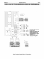
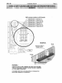
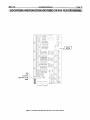
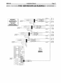
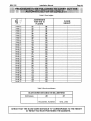
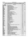
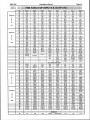
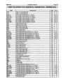
Installation manual
Programme B I 92L du 14110199
Édition n03 du 10 February 2000
MBV-192
Installation Manual
Page 3
WARNING
This document is correct, as far as can be known, at the time of publication and may be modified
without notice.
The information it contains has been scrupulously controlled. However AUTINOR cannot
accept al1 responsibility for errors or omissions:
If you find any inaccuracies or if you have any suggestions you can send your comments written
(by mail andlor fax) to :
Société AUTINOR
Z.A. Les Marlières
59710 AVELIN
S
[33] 20-62-56-00
[33] 20-62-56-01
[email protected]
This document is the property of AUTlNOR from whom it can be bought (from the above
address). It can nonetheless be freely reproduced to convey information to anyone whom it may
be justifiably concern.
Only its integral reproduction, without addition or omissions is allowed.
In the case where this document is quoted, at least :
- A U T I N O R , the name of the Company, and
- the number and date of the original edition
must be mentioned.
MBV-192
Installation Manual
Page 4
SUMMARY
INSTALLATION OF THE CONTROLLER iN THE MACHINE ROOM .........................5
CONNECTION OF DIFFERENTS SUPPLY ................................................................
6
EXTENSION RACK GENERAL VUE ..........................................................................
7
connection of the extension rack to n10 main board AND between boards of the
:....8
extension rack ........................................................................................................
location OF TERMINAL BLOCKS ON NI5 POWER BOARD .....................................9
location AND FUNCTION OF fuses ON N I 5 POWER BOARD ................................I O
CHOICE OF FLOORS AND ENTRANCE FACES FOR A N I 3 BOARD ...................11
location AND FUNCTION OF fuse ON N I 3 FLOOR BOARD ...................................12
location OF TERMINAL BLOCKS ON N I 3 FLOOR BOARD ....................................13
Connecting car calls on collective control (32 floors) ................................................
14
15
Connecting positionning outputs (32 floors) ..............................................................
Connecting landing calls for up and down collective control (32 floors) ....................16
17
fire service (NF) (32 floors) .......................................................................................
door
operator
....................................................................................
18
Connecting the
19
fixing the slotted-tape brackets..................................................................................
PROCEDURE TO BE FOLLOWED TO CARRY OUT THE AUTOMATIC SET-UP
OF LEVELS (114) ......................................................................................................20
What to know before starting off at full speeD (113) ..................................................24
POSlTlONlNG THE EM MAGNETS ON THE SLOTTED TAPE (003-2 Tape head)
-26
(313) ..........................................................................................................................
PARAMETERS CONCERNED THE SLOTTED TAPE ..............................................
27
The TABLE OF parameters (112) ..............................................................................
28
33
The table of INPUTS & OUTPUTS ............................................................................
List of fault codes (112) ..............................................................................................
36
MBV-192
Installation Manual
Page 5
INSTALLATION OF THE CONTROLLER IN THE MACHINE ROOM
Pour
modèles
2, 3, et 4
F
Figure 1 Installation of the controller in the machine room
For the purpose of delivery, the support bar is fixed at the lower side of the soket with
plastic brackets.
Entry for wiring and trunking is at the bottom of the base.
The Controller cabinet measures are :
L = 750 mm, H = 1050 mm, D = 300 mm.
The VF cabinet measures are :
Models 2 , 3 , 4 : L = 562 mm, H = 680 mm, P = 285 mm.
Models 5 and 6 : L = 562 mm, H = 562 mm, P = 285 mm,
Don't forget than the EN-81 part 1 Standard § 6.3.2.1 (a), amended by British
national variation BS 5655 5 V.3.14 requires that :
@) 6.3.2.1 The dimension of machine room shall be sufficient to permit easy and safe access for
servicing personnel to al1 components, especially the electrical equipment.
In particular there shall be provided :
(a) a clear horizontal area in front of the panels and the cabinet. This area is defined as follows .
(N.c)
depth, measured from external surface of the enclosures, at least 0.9 m. This distance may be
reduced to 0.6 m in front of protruding controls (handles, etc.).
width, the full width ofpanel or cabinets by 2.14 m high.
MBV-192
Installation Manual
CONNECTION OF DIFFERENTS SUPPLY
MOTOR
MAIN
SUPPLY
NI0
NI4
NI5
NI3
BG06
VECOl
TB191
= Main board
= Extension rack
= Power board
= Floors board
= Phase Fail Control board
= W V F board Vector (Vectorial Variable Voltage Variation Frequency)
= Transformer
P: 0 1220 1 370 1400 1415V
S: --O191
18V(IA9) - 0 1 16V (2A64)
T2 = Transformer P: 0 1230 1370 1400V
GE32+BG22 S: 0 1 180V (2A) - 0 1 18V (4A) - 0 1 110V (2A)
T3 = Transformer P: 0 1230 1370 1400V
GE32+BG22 S: &4W&o - 0 1 18V (4A) - Q+#W+%)
Page 6
MBV-192
Page 7
Installation Manual
EXTENSION RACK GENERAL VUE
-N I 3 boards on N I 4 board vs
s and entrance faces.
Entrance face 1
/
NI4
/
Fioors 8 to 15
Fioors ?4 to 31
Entrance face 2
F i o o y to 15
Floors 24 to 31
A
MBV-192
Installation Manual
CONNECTION OF THE EXTENSIQN RACK TO N I 0
MAIN BOARD AND BETVVEEN BOARDS OF THE
EXTENSION RACK
--
L
,E&&
LJa-~mB
nYQ-
mOM
if.'
;l"np'
EXTENSION RACK
Page 8
MBV-192
Installation Manual
Page 9
LOCATION OF TERMINAL BLOCKS ON N I 5 POWER BOARD
~Return
OV on N I 0 main board
Common car cal1
Common down landing calls
l _ ~ o m m o n up landing calls
Supply positionning outputs
b-24~Supply car cal1
' e 2 4 RS u p p l y down landing calls
Supply up landing calls
Figure 2 Location of terminal blocks on N15 power board
' MBV-192
Page 1O
Installation Manual
LOCATION AND FUNCTION OF FUSES ON N15 POWER
BOARD
S~are
fuse
for F U I to FU8
2,5A dim: 5 x 20
FAST
FU5 to FU8
Call button panel
protection
ov
2,5A dim: 5 x 20
FAST
FU1 to FU4
Call button panel
protection
ov
2,5A dim: 5 x 20
FAST
Figure 3 Location and function of fuses on N15 power board
MBV-192
Installation Manual
Page Il
CHOICE OF FLOORS AND ENTRANCE FACES FOR A N I 3
BOARD
SW1 Jumper position on N I 3 board :
A mistake dont have any desastrous consequence
but let the software in confusion !
'
MBV-192
Installation Manual
Page 12
LOCATION AND FUNCTION OF FUSE ON N I 3 FLOOR BOARD
FU1
1.6A dim: 5 x 20
FAST
Figure 4 Location and function of fuse on N13 floor board
MBV-192
Installation Manual
Page 13
LOCATION OF TERMINAL BLOCKS ON N I 3 FLUOR BOARD
Figure 5 Location of terminal blocks on NI3 floor board
MBV-192
Page 14
Installation Manual
CONNECTING CAR CALLS ON COLLECTIVE CONTROL
(32FLOORS)
WARNING !
24 V LAMPS
1,2 W max
per output Cx
May attention to the
position of jumper on
each NI3 board.
(see figure
' CHOICE OF FLOOR ... '
in the documentation)
74
INPUT
MBV-192
Installation Manual
Page 17
FlRE SERVICE (NF) (32FLOORS)
FLOOR 31
.............
FLOOR 16
-
;NF6
NFL.............
+NF5 .................
+NF',
.
.
.
.
.
.
.
.
.
.
.
.
.
.
.
.
.
.
NF3 .................
+ NF* ..................
+NF, .........
L
FLOOR 08
1
FLOOR 00
11
INPUT
T~OUTPUT
L
t
-MBV-192
Installation Manual
CONNECTING THE DOOR OPERATOR
Page 18
MBV-192
Installation Manual
FIXING THE SLOTTED-TAPE BRACKETS
Page 19
MBV-192
Installation Manual
Page 20
PROCEDURE TO BE FOLLOWED TO CARRY OUT THE
AUTOMATIC SET-UP OF LEVELS (ii41
BEFORE STARTING :
This levelling adjustment is done in INSPECTION (INS) mode and
not i n MAN. For this connect the inspection wire coming from the car roof
to INS, and bridge MAN and OV.
Do not put the magnets on the tape, but take them with you, as well as this
installation manual.
This automatic relevelling procedure allows you to measure and register directly in
the controller the landing heights of each corresponding floor. Each level corresponds to
an altitude on the slotted tape.
The lowest level is 00 00.
PROCEDURE TO FOLLOW :
1) Turn the switch to INS.
2) Switch the MB992 power off and then on again.
3) With the left-hand switch of the BG17 communication tool on PAR, programme 80 at
address F8. Adapt your Inspection speed V I (Ad 003).
4)
Climb ont0 the car roof and take the lift down to the lowest level. Stop exactly at the
floor level !
5) Press the « STOP » button on the car roof.
6)
Press GM and GD at the same time for 5 seconds.
You can always correct the the last registered height, as long as
you have not moved by more than 20 centimetres.
7) Position the ED magnet above the 003 tape-head at a height (D) corresponding to
the slow down distance required (see graph on next page).
Vn : Nominal speed in metres per second.
D : Slow down distance in metres
Example : If the lift speed is 1.60 mls, the graph page 21 recommends a slow down
distance (D) between 2 m 00 and 3 m 00, in Our example : 2.50 m.
MBV-192
Installation Manual
Page 21
PROCEDURE TO BE FOLLOWED T 0 CARRY OUT THE
AUTOMATIC SET-UP OF LEVELS (214)
0.5
1
1.5
2
2.5
SPEED IN M ETRES PER SECOND
Figure 6 Slow down distance D in relation to the nominal speed
Figure 7 Positioning of "ED" magnet
'
'."MBV-192
Installation Manual
Page 22
PROCEDURE TO BE FQLLOWED TO CARRY OUT THE
AUTOMATIC SET-UP OF LEVELS (314)
8) Release the « STOP » button on the car roof and go upto level 1 on inspection,
stopping exactly at floor level !
Press the « STOP » button on the car roof.
10) Press GM and GD at the same time for 5 seconds.
9)
The software will memorize the height corresponding to level 1..
11) Repeat steps 7) to 9) until you reach the highest level.
12) Come back down to the lowest level.
By passing the ED magnets coming down, you automatically load the slow-down
distance used by al1 levels going up or coming down. In addition the value 80
programmed at address F8 will reset to 00 to exit the automatic level set-up
procedure.
13) Move the lift towards the machine room on inspection, and leave the car roof, leavina
the switch still on inspection.
14) Turn the MBi92 power off and then back on again.
If fault code 61 is shown on the communication tool,
a mistake has been made during the level set-up procedure,
and the whole procedure needs to be done again
...
15) If the fault code 61 does not appear, cut the safety lane.
Copy down each floor heiaht at addresses 90 to CF in the table on page 23, so that
later on you can check the lift's stopping precision (Table 1 Floor heights) and the
slow down distance read at addresses do and d l (Table 2 Slow down distance).
16) Turn the inspection switch on the car roof to Normal.
17) Return to the machine room.
18) Read the chapter « What to know before starting of at full speed » before
reconnecting the safety lane. In this way you can check that the lift carries out
correctly its reset sequence.
MBV-192
Installation Manual
Page 23
PROCEDURE TO BE FOLLOWED TO CARRY OUT THE
AUTOMATIC SET-UP OF LEVELS (414)
Table 1 Floor heights
Table 2 Slow down distance
SLOW DOWN DISTANCE IN MlLLlMETERS
Add resses
do
dl
thousands, hundred
tens, units
CHECK THAT THE SLOW DOWN DISTANCE "D" CORRESPONDS TO THE HEIGHT
AT WHlCH YOU HAVE POSlTlONED THE MAGNETS.
>
t
MBV-192
Installation Manual
Page 24
WHAT TO KNOW BEFORE STARTING OFF AT FULL SPEED (in)
1. Adjustment of the Synchronous Speed
At the moment, V2 and the synchronous speed (VSy) are the same value.
1) Select address 114 on the frequency drive communication device.
2) Carry out a full speed movement, and read the synchronous speed displayed. Copy
this value into parameter Vsy, address 006.
II. Automatic adjustment of the up stopping precision
This procedure only works in the case of a slow down distance including the relevelling
speed VO.
1) Send the lift to the lowest level.
2) With the left-hand switch of the BG17 communication tool on PAR, programme 40 at
address F8.
Warnins : when you slide the switch back up, F8 will be displayed followed by 42
3) Send the car up one floor on normal.
When the car stops, the value 42 programmed at F8 will reset to 00 to exit the
automatic adjustment procedure.
Warninci : the lift may perhaps not be exactly at floor level.
This is normal ..., it will be at floor level after the next journey.
III.Automatic adjustment of the down stopping precision
This procedure only works in the case of a slow down distance including the relevelling
speed VO.
1) Send the lift to the highest level.
2) With the left-hand switch of the BG17 communication tool on PAR, programme 20 at
address F8.
Warninci : when you slide the switch back up, F8 will display followed by 21.
3) Send the car down one floor on normal.
When the car stops, the value 21 programmed at F8 will reset to 00
to exit the automatic adjustment procedure.
Warninçi : the lift may perhaps not be exactly at floor level.
This is normal ..., it will be at floor level after the next journey.
To find out the stopping precision at each level, with the left-hand switch of the
BG17 on RAMI check the height counter at 51 and 50.
The value is given in impulses and in hexadecimal. 1 impulse = 2 millimetres.
Height counter
at addresses
51 and 50
A d 51 = 00
Ad 50 = 03
Example :
Sending the car to the very bottom, if you
read 00 at 51 and 03 at 50, this means that
the car stopped 3 impulses (about 6mm)
,from the target (00 03).
MBV-192
Installation Manual
Page 25
PARAMETERS ADJUSTMENT AT FULL SPEED (213)
IV.Adjustment of the direct approach precision
At address 006, segment 6 should be on.
1) Select address 50, with the little left-hand red switch in the RAM (upper) position, and
send the lift to the bottom floor. The tape head may show a positive value eg 09 (i.e. 9
impulses x 2mm = 18mm), which means that the car has stopped 18mm above floor
level.
lncrease the value programmed at address 008 (DV2) by this 18mm.
If the lift stops after floor level, reduce the value programmed at address 008 (DV2) by
these 18mm.
V.Automatic adjustment of the hysterisis zone
1
This must be done if the lowest level is not the main floor.
1) Position the lift above the ED magnets.
2) With the lefi-hand switch of the BG17 communication tool on PAR, programme 10 at
address F8.
3) Send the car up one floor and then down one floor, so that the tape-head passes the
ED magnets in both directions.
VI.Positioning of EM magnet at top floor
Position the EM magnet at the slow-down point for the top floor, this may be useful if
the lift does not cross the bottom magnets very often.
To carry out this operation, you will need the following elements :
An 003-2 tape-head.
An N70 interface board for an 003-2 tape-head.
A pair of magnets to position as shown on page 26.
1) During normal operation, when the lift stops exactly at the desired floor, send the lift
up to the top floor and position the EM magnets to obtain the desired slow-down
distance (the position of the EM magnets is roughtly the same as that of the ED
magnets).
2) If afterwards when coming back to the top floor, the lift does not stop at floor level,
move the EM magnets to the value corresponding to the reset heigt.
MBV-192
Installation Manual
Page 26
POSlTlONlNG THE EM MAGNETS ON THE SLQTTED TAPE
(003-2 TAPE HEAD) (313)
FLOOR N
ZONARM
UP STOPPING ZONE
ZDEVER
UP DOOR UNLOCKING ZONE
UP SLOW
SPEED ZONE
.
.
.
.
.
.
.
.
.
.
.
.
.
.
.
.
.
.
.
.
.
.
.
.
.
.
.
.
.
.
.
.
.
.
.
.
.
.
.
.
.
.
.
.
.
.
.
.
.
.
.
.
.
.
.
.......
.
.
.
.
.
.
.
.
.
.
.
.
.
.
.
.
.
.
.
.
.
.
.
.
.
.
.
.
.
.
.
.
.
.
DOWN SLOW
SPEED ZONE
FLOOR F-1
-
DOWN SLOW
SPEED ZONE
ZDEVER
DOWN DOOR UNLOCKING ZONE
.
.
.
.
.
.
.
.
.
.
.
.
.
.
.
.
.
.
v v
ZONARD
DOWN STOPPING ZONE
MBV-192
Installation Manual
Page 27
PARAMETERS CONCERNED THE SLOTTED TAPE
t I
L
C=l
O
ZONEPV = SLOW SPEED ZONE
n
0
.
.
.
.
.
.
.
.
.
.
.
ZDEVER = DOWN DOOR UNLOCKING ZONE
ZONARD
LEVEL L
4
= DOWN STOPPING ZONE
ZONARM = UP STOPPING ZONE
ZDEVER = UP DOOR UNLOCKING ZONE
.
.
.
.
.
.
.
.
.
.
Designation
Name
Address
ZDEVER
DOOR UNLOCKING ZONE ........................................ d4 and d5
ZONARM
UP STOPPING ZONE .......................................................
d2
ZONARD
DOWN STOPPING ZONE .................................................
d3
ZONYST
HYSTERlSlS ZONE ..........................................................
dd
Parameters linked to the relevelling
......................................................
BNDISO
RELEVELLING JUMP
ZONARI
RELEVELLING STOPPING ZONE ....................................
dC
d7
Parameters linked to the slow-down distance
DMlNV2
MINIMUM DISTANCE FOR V2 ........................................ d8 and d9
ZONPVI
SLOW SPEED ZONE 1 = V I SLOW DOWN DISTANCE .. dA and db
ZONPV2
SLOW SPEED ZONE 2 = V2 SLOW DOWN DISTANCE .. do and d l
Parameters linked to the floor eights
ALTNIVOO
to
ALTNIV31
FLOOR ElGHT LEVEL 00 ....................
.
......................... 91 and 90
to
to
FLOOR ElGHT LEVEL 31 ................................................. CF and CE
For the floor heights, see page 23
All of the information shown in the above table is shown in millimetres and in
decimal, except the floor heights.
When the information is given over 2 addresses, the first address shows the
thousands and hundreds, and the second shows the tens and units.
Example :
For a slow-down distance (or slow speed zone) of 800 mm (80 cm), you
will read 08 at address do, and 00 at address d l , i.e. 0800 millimetres.
MBV-192
Installation Manual
THE TABLE OF PARAMETERS (112)
Page 28
MBV-192
Installation Manual
Page 29
THE TABLE OF PARAMETERS (212)
PARAMETERS ON DECIMAL NUMBER
SLOW SPEED ZONE 1 V2 (SPEED 2) (IN DECIMETER)
SLOW SPEED ZONE 1 V2 (SPEED 2) (IN MILLIMETER)
SLOW SPEED UP STOP ZONE (IN MILLIMETER)
SLOW SPEED DOWN STOP ZONE (IN MILLIMETER)
UN-LOCKING ZONE (IN DECIMETER)
UN-LOCKING ZONE (IN MILLIMETER)
STOP ZONE OF RE-LEVELLING (IN DECIMETER)
STOP ZONE OF RE-LEVELLING (IN MILLIMETER)
BAN ZONE ON HIGH-SPEED V2 (IN DECIMETER)
BAN ZONE ON HIGH-SPEED V2 (IN MILLIMETER)
SLOW SPEED ZONE (VI) (IN DECIMETER)
SLOW SPEED ZONE (VI) (IN MILLIMETER)
INCREMENT STEP FOR RE-LEVELLING (MAXI. 8)
HYSTERESIS ZONE FOR MAGNET RECALL
do
dl
d2
d3
d4
d5
d6
d7
d8
d9
dA
dB
dC
dd
EO
E1
E2
E3
E4
E5
E6
E7
E8
E9
EA
EB
EC
ED
EE
EF
FO
F1
F2
F3
F4
F5
F6
F7
FF
MSQCAB - MASK FOR CAR CALLS FROM 7 TO O
MSQCAB - MASK FOR CAR CALLS FROM 15 TO 8
MSQCAB - MASK FOR CAR CALLS FROM 23 TO 16
MSQCAB - MASK FOR CAR CALLS FROM 32 TO 24
MSQMO MASK FOR ASCENDING FLOOR CALLS FOR LEVELS 7 TO 1
MSQMO - MASK FOR ASCENDING FLOOR CALLS FOR LEVELS 15 TO 8
MSQMO - MASK FOR ASCENDING FLOOR CALLS FOR LEVELS 23 TO 16
MSQMO MASK FOR ASCENDING FLOOR CALLS FOR LEVELS 32 TO 24
MSQDE - MASK FOR DECENDING FLOOR CALLS FOR LEVELS 7 TO O
MSQDE - MASK FOR DECENDING FLOOR CALLS FOR LEVELS 15 TO 8
MSQDE - MASK FOR DECENDING FLOOR CALLS FOR LEVELS 23 TO 16
MSQDE - MASK FOR DECENDING FLOOR CALLS FOR LEVELS 32 TO 24
MSQCAB - MASK FOR CAR CALLS FROM 7 TO O
MSQCAB - MASK FOR CAR CALLS FROM 15 TO 8
MSQCAB - MASK FOR CAR CALLS FROM 23 TO 16
MSQCAB - MASK FOR CAR CALLS FROM 32 TO 24
MSQMO - MASK FOR ASCENDING FLOOR CALLS FOR LEVELS 7 TO 1
MSQMO - MASK FOR ASCENDING FLOOR CALLS FOR LEVELS 15 TO 8
MSQMO - MASK FOR ASCENDING FLOOR CALLS FOR LEVELS 23 TO 16
MSQMO - MASK FOR ASCENDING FLOOR CALLS FOR LEVELS 32 TO 24
MSQDE - MASK FOR DECENDING FLOOR CALLS FOR LEVELS 7 TO O
MSQDE - MASK FOR DECENDING FLOOR CALLS FOR LEVELS 15 TO 8
MSQDE - MASK FOR DECENDING FLOOR CALLS FOR LEVELS 23 TO 16
MSQDE - MASK FOR DECENDING FLOOR CALLS FOR LEVELS 32 TO 24
F
A
C
E
-
-
CA
1
CB
1
INS
1
MINIBLOC
POMP 1
NIV
1
1O
8
Nol
F
A
C
E
NO2
6
"
MBV-192
Installation Manual
THE PARAMETERS IN ALPHABETICAL ORDER (113)
Page 30
MBV-192
Installation Manual
THE PARAMETERS IN ALPHABETlCAL ORDER (Y3)
Page 31
MBV-192
Installation Manual
Page 32
THE PARAMETERS IN ALPHABETICAL ORDER (313)
1
1 Option basernent [sous-sol] (incompatibility with selectives doors)
1
1
1
dF
MINIBLOC
CA
CB
INS
POMP
NIV
«ION
u 8 >>
a6»
Breack beam A of the tape-head 0 0 3
Breack beam B of the tape-head 0 0 3
Inspection mode
Fire service
Level (The car is at level xx)
Break of safety chain before 10 (locking door)
Break of safety chain before 8 (closing door)
Cut of safety chain before 6 (al1 of the other contacts)
FF
FF
FF
FF
FF
FF
FF
FF
7
6
5
4
3
2
1
O
MBV-192
Installation Manual
THE TABLE OF INPUTS & OUTPUTS
Page 33
-
MBV-192
Installation Manual
Page 34
INPUTS & OUTPUTS LIST IN ALPHABETICAL ORDER (112)
MBV-192
Installation Manual
Page 35
INPUTS & OUTPUTS LIST IN ALPHABETICAL ORDER (212)