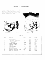
1
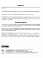
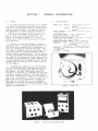
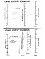
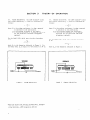
Model 6105 Resistivity
Instruction Manual
Contains Operating
Publication Date: October 1972
Document Number: 31415
Adapter
and Servicing Information
WARRANTY
Keithley Instruments, Inc. warrants this product to be free from defects in material and workmanship for a period of 1 year from date of
shipment.
Keithley Instruments, Inc. warrants the following items for 90 days from the date of shipment: probes, cables, rcchargcablc baitcries,
diskettes, and documentation.
During the warranty period, we will, at our option, cithcr repair or replace any product that proves to be defective.
To exercise this warranty, write or call your local Keithley representative, or contact Keithley headquarters in Cleveland, Ohio. You will
bc given prompt assistance and rctum instructions. Send the product, transpot%~tion prepaid, to the indicated service facility. Repairs
will be made and the product returned, transportation prepaid. Repaired or replaced products are warranted for the balance of the origi“al warranty period, or at Icast 90 days.
LIMITATION
OF WARRANTY
This warranty dots not apply to defects resulting from product modification without Keithley’s express written consent, or misuse of
any product or part. This warranty also does not apply to fuses, software, non-rechargeable batteries, damage from battery leakage, or
problems arising from normal weas or failure to follow instructions,
THIS WARRANTY IS IN LIEU OF ALL OTHER WARRANTIES, EXPRESSED OR IMPLIED, INCLUDING ANY IMPLIED
WARRANTY OF MERCHANTABILITY
OR FITNESS FOR A PARTICULAR USE. THE REMEDIES PROVTDED HEREIN ARE
BUYER’S SOLE AND EXCLUSIVE REMEDIES.
NEITHER KEITHLEY INSTRUMENTS, INC. NOR ANY OF ITS EMPLOYEES SHALL BE LIABLE FOR ANY DIRECT, INDIRECT, SPECIAL, INCIDENTAL OR CONSEQUENTIAL DAMAGES ARISING OUT OF THE USE OF ITS INSTRUMENTS AND
SOFTWARE EVEN IF KEITHLEY INSTRUMENTS, INC., HAS BEEN ADVISED IN ADVANCE OF THE POSSIBILITY OF
SUCH DAMAGES. SUCH EXCLUDED DAMAGES SHALL INCLUDE, BUT ARE NOT LIMITED TO: COSTS OF REMOVAL
AND INSTALLATION, LOSSES SUSTAINED AS THE RESULT OF INJURY TO ANY PERSON, OR DAMAGE TO PROPERTY
SECTION
l-l.
1.
GENERAL
INFORMATION
GENERAL.
a. The Model 6105 Resistivity
Adapter is a guarded
te*t fixture
for measuring volume and surface resistivities
af materials
when used with a regulated
power
supply and an eleccromecer.
The complete sysc?m permits measurement of volume resistivicy
from 10 c0
3 x 10¹⁹ ohm-cm and surface resiscivicy
from lo3 co
5 x 10¹⁸ ohms, in accordance with procedures
of cbe
American Society
far Testing
and Materials.
The
Adapter can accommadace samples up co 4 inches in
diameter
and 114 inch chick with excitation
voltages
up to 1000 volt*.
b. The Model 6105 has been designed c0 minimize
The electrode
configurations
conmeasurement error.
form co the ASTM recommendations
for measurement of
electrical
resisrance
of insulating
materials.
The
test sample is shielded
co prevent
stray pickup.
The
guard ring circuit
is arranged c" minimize
ieakage
currents
from the measuring circuit.
Uniform pressure
is always applied
over the measuring area, because the
cesc sample is held beween the spring-loaded,
guarded
electrode
and the ""e-pound
cesc weight assembly.
Due
co these cansideracions,
measurement accuracy depends
primarily
upon the accuracy of the voltage
source and
the electrometer.
C. Recwmended inscrumencs
for "se with the Model
6105 are the Keichley
Model 240A Regulated
High Voltage Supply and the Keichley
Model 610C Multi-Range
The Model 240A provides
excicacion
Electrometer.
volcages
up c" 1200 volts in calibrated
one-volt
steps.
Ifs oufput is accurate within
1%. The Model 61OC provides direct
reading current
ranges c" lo-l4
ampere
Its accuracy is fZ% of full
scale f" 10-11
full
scale.
ampere, and f4% of full
scale beyond.
Although
the
Model 240A and the Model 610C are the reccmmended
instruments
for "se with the Resistivity
Adapter,
the
Model 6105 is compatible
vich.all
Keithley
high voltage
supplies
and electrometers.
SAMPLE SIZE:
Maximum:
Minimum:
4-inch diameter
(10.2-a
diameter)
Z-l/Z-inch
diameter
(6.3-cm
diameter)
inch co 114 inch (0.159 cn
SAMPLE THICKNESS: l/l6
to 0.635 cm).
TEST VOLTAGE i&GE:
1 volt
c" 1000 vales.
MAXIMUM TEST VOLTAGE: 1000 "OlCS.
""LUME RESISTI"ITY
RANGES: 1.5 x 10² to 1.5 x 10¹⁸
ohm-inches
(lo3 co 101' ohm-cm).
SURFACE RESISTI"ITI
RANGES: lo3 cr, 10IS ohms.
CmNECTORS: Power:
Teflon insulated
uhf-type
receptacle.
Electrometer:
BNC-type recepcac1e.
"IMENSlONS:
6 inches wide x 4-l/2
inches deep x
4 inches high.
NET WEIGHT: 3 pounds.
FIGURE 1.
MODEL 6105
SECTION
2.
2-l.
PREPAEATION FOR USE. The Model 6105 is shipped
with two thumb-screw
fasteners
holding
the test weight
to the guard ring.
Remove ehese fasteners
and store
for later
use.
These are used only for shipping
and
they should not be used during measurements.
In
mounting the sample for measurement,
make sure there
are no conductive
paths between the electrodes
other
than those through the sample.
The sample should be
supported
from the electrodes
so that the elecrrodes
do not touch anything
excep,t the sample.
Do nof handle
the sample with bare fingers;
acetate
rayon gloves are
recomended.
For best results,
clean the sample surfaces with an alcohol
and ether mixture
or'other
suitable solvent.
a. Volume Resisrivity
Measurements.
Place the
short circuit
plug o"er the upper wo jacks,
leaving
"VOLITME" clearly
visible.
Inserf
the banana plug from
the fest weight assembly into the bottom jack.
Close
the Model 6105 cover.
An interlock
switch disconnecrs
the potential
to the sample if the co"er is opened.
Apply the power supply voltage.
Read the current
on
the electrometer.
The value of the volume resisrivity
p, is found through one of the following
calculations:
p = x3.53
I
v
ohm-inches
_ 22.9
v
ohm-centimeters
% 1
where p is the volume resistivity
of
V is the applied
voltage
from
in volts;
ti is the average thickness
of
inches;
tc is the average thickness
of
centimeters;
I is the current
reading
from
the sample;
rhe parer supply
the sample
in
the sample
in
the elecrrmerer.
b.
Surface Resisrivicy
Measurements.
Place the
short circuit
slug over the lower two iacks, leavina
"SURFACE" cle&ly-visible.
Insert
the-ban&a
plug I
from the fesf weight assembly into the top jack.
Close
Apply the power supply "oltthe Model 6105 cover.
age.
Read the current
on the electrometer.
The value
of the surface resistivity
is found through the following calculation:
where
0 is
V is
in
I is
the surface
the applied
volts;
rhe cu+rent
resistivity
of the sample;
voltage
from the power supply
reading
from the electrometer.
2-2.
CONNECTIONS. Connect the power supply to the
uhf-type
recepracle.
Connect the electrometer
to the
bnc-type
receptacle.
Place rhe sample under the test
weight as shown in Figure
5.
The sample thickness
should be between l/l6
and 114 inch (0.159 and 0.635
cm). The diameter
should be beween 2-l/2 and 4 inches
(6.29 and 10.2 cm).
2-3.
The Model 6105 Demits
eas" measuePROCEDURE.
menc Of a sample.
The test sample is placedabeween
the two electrodes;
the desired
test potential
is
selected
from the voltage
supply and the current
passing through the test sample is measured by the electrometer . From readings
from the voltage
supply and
the electrometer,
the resistiviries
can be computed.
I
1
118 in.
.31
FIGURE
2
3.
DIMENSIONING
cm.
FOR MODEL 6105
I
ELECTRODES
SURFACE RESISTIVITY NOMOGRAPH
p,
2-
100
i
=
10’0
=
10”
1
: 53.36 yI ohms
z
0
,O,
2
= 3.56.10”ohm,
_--__--
_*--
_*--
z
.ly--”
e
10-a
y
lo-”
-
10-12
10’2
-
;
;i
lo-’
1
-
EXAMPLE:
3.0x lO%mps
200 “d’s
3
10’3
___
_A-2
!s
10”
-
.r
10’5
VOLTAGE
=
10’6
2
10”
CURRENT
RESISTIVITY
VOLUME RESISTIVITY NOMOGRAPH
-
10-12
-
10-l’
.--__
=
10-10
kc
5
z
i
5
-
10-q
2
s
l-i
=
10-e
lo9
I
THICKNESS
VOLTA1GE
RESISTIVITY
2-3 10-T
CURRENT
SECTION
VOLUME RESISTIVITY.
3-l.
that volume resistivity,
follows:
3.
THEORY
The ASTM Standard*
states
o, shall be calculated
as
where K is the volume resistance,
in ohms, measured
as specified
in the publication;
t is 'the average thickness
of the sample:
A is the effective
area of the guarded electrode
for the particular
elecmode
arrangement
employed.
For the Model 6105, which
A is
uses circular
OF
OPERATION
3-2.
SURFACE KESISTI"ITY.
that surface
resistivity,
follows:
The ASTM Standard*
states
s, shall be calculated
as
where R is the surface
resistance,
in ohms, measured
as specified
in tl>e publication;
g is the distance
between the electrodes;
P is the effective
perimeter
of the guarded
electrode
for the particular
electrode
arrangemenr
employed.
electrodes,
For the Model 6105, which
P, is
IT2
uses circular
electrodes,
A=$.
P = Do r
where Do is the dimension indicated
in Figure 3. For
the Model 6105, Do is equal to Z-118 inches or 5.40 cm.
where Do is
the dimensj~on indicated
in Figure
VOLUME
FIGUP.% 4.
"OLum
*American Society
for Testing
and Materials,
Methods of Test for Electrical
Resistance
acing Materials,
ASTM Designation
D257-66
4
FIGURE 5.
RESISTIVITY
Standard
of Insul-
SOWACE RESISTIVITY
3.
SECTION
1
2
3
4
5
6
8
9
10
II
4.
MAINTENANCE
ReSiSti”ity
Adapter
. ‘Test Weight Assembly
Test Weight, Stainless
Steel
. Handle Assembly
Test Lead Assembly
Banana Pl.“g
FE fener , Thumb-screw
Banana Jack (3 rcqd.)
chard Ring
. Guard Ring Insulator
Test Plate Assembly
Test Plate
Receptacle,
bnc
&ate of bnc receptacle)
Receptacle,
uhf, Mil. x0. so-239
im
of uhf receptacle,
Mil. NO. 49190
ildifed
Short circuit
Plug
108-303
108-901
31-221
31-002
6804
5127
80164
801~64
80164
80164
80164
74970
80164
7497"
80164
80164
80164
80X4
02660
02660
91737
91737
80164
wade1 6105
15702A
16371A
16231A
157063
Lx-5
SK-4
W-6
1637OPx
15708A
15709B
3~6369A
cs-15
cs-44
cs-64
c-49
23443A
Test Instrumentation Group
Keithley Instruments, Inc.
20775 Aurora Road
Cleveland,
Ohio 44139
Printed in the tJ.S.A