1
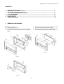
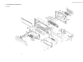
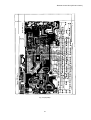
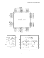
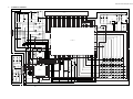
Remote Control Unit (SS-10/11/12/21)
Service Manual
Remote Control Unit
SoundSpace 10/11/12/21
1
Remote Control Unit (SS-10/11/12/21)
CONTENTS
1.
2.
3.
4.
5.
6.
7.
1.
REMOVAL PROCEDURES ................................................................................................................................
MECHANISM ASS'Y AND PARTS LIST ...........................................................................................................
MOUNTING DIAGRAMS AND PARTS LIST .....................................................................................................
3.1. Main P.C.B. Ass'y/Sensor P.C.B. Ass'y .................................................................................................
IC BLOCK DIAGRAMS ......................................................................................................................................
BLOCK DIAGRAM .............................................................................................................................................
WIRING DIAGRAM ............................................................................................................................................
SCHEMATIC DIAGRAM ....................................................................................................................................
2
3
5
5
8
10
11
12
REMOVAL PROCEDURES
Refer to Figs. 1.1 to 1.3.
(1) Open F01 (Battery Cover).
(2) Remove screws F02 (4 pcs.), F03 (1 pce.) to detach
F04 (Bottom Cabinet Ass'y) and F05 (Front Panel
Ass'y).
(3) Remove screws F06 (4 pcs.) to detach F07 (Main
P.C.B. Ass'y) from F05 (Front Panel Ass'y).
(4) Remove screws F08 (2 pcs.) to detach F09 (Sensor
P.C.B. Ass'y) from F04 (Bottom Cabinet Ass'y).
Fig. 1.2
Fig. 1.1
Fig. 1.3
2
Remote Control Unit (SS-10/11/12/21)
2.
MECHANISM ASS'Y AND PARTS LIST
2.1. Synthesis
Fig. 2
3
Remote Control Unit (SS-10/11/12/21)
2.1. Synthesis
Schematic
Ref. No.
M1
M2
M3
M4
M5
M6
M7
M8
M9
M10
M11
M12
M13
M14
M15
M16
M17
M18
M18-1
M18-2
M19
M20
M21
M22
M23
M24
M24-1
M24-2
M25
M26
M27
M28
M29
M30
M31
M32
M33
M34
M35
M36
M37
M38
M39
M40
M41
M42
M43
M44
M45
M46
M47
M48
M49
M50
M51
M52
M53
M54
M55
Part No.
—
2H00289A
2H00326A
2H00327A
2H00328A
2H00290A
2H00291A
2H00292A
2J00270A
2J00271A
2H00293A
2J00272A
2H00294A
2H00295A
2J00273A
2H00296A
2J00274A
2H00297A
2E00198A
2H00298A
2H00329A
2H00299A
2H00300A
0H08553C
0J08474B
2H00301A
2H00302A
2E00199A
2E00200A
2E00201A
2H00303A
0H08554C
0J08475B
2H00304A
2H00305A
2H00306A
2J00275A
2J00276A
2H00307A
2J00277A
2H00308A
2J00278A
2H00309A
2H00310A
2H00311A
CB00733A
2J00279A
2J00280A
2J00281A
2J00282A
2J00283A
2E00183A
2E00202A
2H00312A
2J00284A
2J00291A
2H00313A
CB00734A
2J00285A
2H00314A
2E00203A
2E00204A
2J00286A
2J00287A
2H00315A
Description
Synthesis
Door SS-11
Door SS-10
Door SS-21
Door SS-12
Skip Button Cover
Skip Button
Enter Button
RMC Skip Cushion
RMC Enter Cushion A
Push Button
RMC Enter Cushion
Button Cover
Search Button
RMC Enter Cushion B
Volume Button
RMC Volume Cushion
Door Cover
9 FLT2005 ZN3K
Name Plate SS-10/11/12
Name Plate SS-21
Top Window
Side Cover L SS-10/11/12
Wooden Cover L SS-21
RMC Side Bracket L SS-21
Side Bracket
Top Cabinet
2 BID2008 ZN3A
Fiber Washer 3.2x8x0.5
7 BID2605 ZN3K
Side Cover R SS-10/11/12
Wooden Cover R SS-21
RMC Side Bracket R SS-21
Light Button
Touch Panel NAS-01-1D
Shield Cover
Cabinet Cushion H
Cabinet Cushion W
Shield Plate
Filter Paper
Lens
RMS Lens Cushion
Filter Plate
Slide Knob
LED Housing LED-4Y
Main P.C.B. Ass’y
Battery Spring B
Battery Spring C
Battery Spring D
PVC Spacer
Battery Spring E
7 BID2608 ZN3A
7 BID2605 ZN3A
Front Panel
Rubber Button SS-10/11/12
Rubber Button SS-21
LED Housing LED5-4.5T
Sensor P.C.B. Ass’y
Sensor Plate
Bottom Cabinet
7 BID2610 ZN3K
7 FLT2608 ZN3K
Battery Spring A
Battery Sponge 25x50x12t
Battery Cover
Q'ty
1
1
1
1
1
4
1
1
1
3
3
1
1
5
1
1
1
4
1
1
1
1
1
1
1
4
4
2
2
1
1
1
1
1
1
3
2
1
1
1
4
1
2
3
1
1
1
1
4
1
4
2
1
1
1
3
1
1
1
4
1
1
1
1
4
Remote Control Unit (SS-10/11/12/21)
3.
MOUNTING DIAGRAMS AND PARTS LIST
3.1. Main P.C.B. Ass'y/Sensor P.C.B. Ass'y
Fig. 3.1 (Component Side)
5
Remote Control Unit (SS-10/11/12/21)
Fig. 3.2 (Dip Side)
6
Remote Control Unit (SS-10/11/12/21)
NOTES: 1. Abbreviations
TR – Transistor, SID – Silicon Diode, ZD – Zener Diode, Varicap – Variable Capacitance Diode
RK – Carbon Resistor, RM – Metal Film Resistor, RF – Fail Safe Type Resistor,
RC – Cement Resistor, CE – Electrolytic Capacitor, CML – Mylar Capacitor,
CC – Ceramic Capacitor, CPP – PP Capacitor, CMM – Metalized Mylar Capacitor,
CSP – Polystyrene Capacitor, C – Mica Capacitor, CT – Tantalum Capacitor
2. Description of capacitor: 10 16V = 10µ 16V
3. Parts marked with * show chip parts.
● Main P.C.B. Ass'y
Schematic
Ref. No.
Schematic
Ref. No.
C3
C5
C6
C9
IC
C10-13
UPD17203AGC-767
C15
IC
S-29530A
C16
IC
UPD78062GF-061 CN1
IC
TC7W125FU
CN2
TR 2SA812M5*
TR 2SC1623L6*
TR
2SB1132Q,R E5-R*
TR 2SK2158
TR 2SC945P,Q
TR 2SK2541 FET
TR 2SA733P,Q
TR 2SK2541 FET
TR 2SC945P,Q
TR 2SA733P,Q
TR 2SK2541 FET
SID 1SS133
SID 1SS133
SID MA719
SID
LL4148 GS08 EI-L
ZD RD3.9ES-AB1
LCD Display FTD-17903
LED 3Q NSPW310BS
White
Resonator CST4.0MGW
SW Slide 00221453
SW Tact SKHMPW
E010 KHM903
SW Tact
SKHVBE3520-CP
RK 91K
1/6W
RK 82K
1/6W
RK 100K 1/6W
RK 47K
1/6W
RK 1M
1/6W
RK 1K
1/6W*
RK 10K
1/6W*
RK 100K 1/4W*
RK 3.3K 1/4W*
RK 220K 1/4W*
RK 100K 1/4W*
RK 33
1/6W
RK 6.8
1/6W
RK 10K
1/6W
RK 2.2K 1/4W*
RK 100K 1/4W*
RK 4.7K 1/6W
RK 100K 1/4W*
RK 10K
1/4W*
RK 0
1/4W*
RK 1K
1/4W*
RK 100K 1/4W*
RK 220
1/6W
RK 4.7K 1/6W
RK 10
1/6W
RK 100K 1/6W
CE 4.7 6.3V M Mini
CE 100 10V M Mini
Part No.
Description
CB00733A Main P.C.B. Ass'y
IC1
2B10304A
IC2
IC3
IC4
Q2,3
Q4
Q5
2B10305A
2B10306A
2B10307A
2B10308A
2B10309A
2B10310A
Q6
Q9
Q10
Q11,12
Q13
Q14
Q15
Q16
D1
D3
D4
D5-13
0B12847A
0B01872A
2B10256A
0B06013A
2B10256A
0B01872A
0B06013A
2B10256A
0B12249A
0B12249A
0B12745A
2B10311A
ZD1
LCD1
LED4-6
2B10312A
2B90080A
2B10280A
CF1,2
S1,2
RS1
2B90081A
2B70043A
2B70044A
K69
0B70219A
R9
R10
R11
R12
R13,14
R15-18
R19
R20
R21
R22
R29-31
R32-34
R38
R39
R40
R41
R42
R43
R50-53
R54
R55
R56
R57
R58
R59
R60
C1
C2
0B09700A
0B09651A
0B09725A
0B09717A
0B09749A
0K20061A
0K20068A
0K20075A
0K20064A
2B20047A
0K20075A
0B09641A
0B09625A
0B09701A
0K20063A
0K20075A
0B09693A
0K20075A
0K20068A
0K20102A
0K20061A
0K20075A
0B09661A
0B09693A
0B09629A
0B09725A
0B40157A
0B48040A
● Sensor P.C.B. Ass'y
Part No.
0B40176A
2B40045A
0B43144A
0B40173A
0B43064A
0B43064A
0B43144A
2B80216A
2B80217A
7
Description
CE 4.7 50V M Mini
CML 100P 50V K
CC 0.1 50V J*
CE 1 50V M Mini
CC 0.01 50V J*
CC 0.01 50V J*
CC 0.1 50V J*
Base FMZ 4P Side
Base FFC 6P Side
Schematic
Ref. No.
Q1
D2
LED1-3
RLED1
R1-3
R4
R5
R6
R7
R8
C4
CN2
Part No.
Description
CB00734A Sensor P.C.B. Ass'y
0B10399A
0B12249A
2B90082A
2B90083A
0B09605A
0B09661A
0B09699A
0B09693A
0B09713A
0B09693A
2B40045A
2B80217A
TR 2SC2001L
SID 1SS133T-77
LED SLR-932A Infrared
LED REC. PH310 Black
RK 1
1/6W
RK 220
1/6W
RK 8.2K 1/6W
RK 4.7K 1/6W
RK 33K
1/6W
RK 4.7K 1/6W
CML 100P 50V K
Base FFC 6P Side
Remote Control Unit (SS-10/11/12/21)
4.
IC BLOCK DIAGRAMS
Fig. 4.1
8
Remote Control Unit (SS-10/11/12/21)
Fig. 4.2
Fig. 4.3
Fig. 4.4
9
Remote Control Unit (SS-10/11/12/21)
5.
BLOCK DIAGRAM
Fig. 5
10
Remote Control Unit (SS-10/11/12/21)
6.
WIRING DIAGRAM
Fig. 6
11
Remote Control Unit (SS-10/11/12/21)
SCHEMATIC DIAGRAM
MAIN P.C.B.
Q15
2SA733
Q14
2SC945
Q5
2SB1132
R59
10
LCD1
FTD-17903
R57
220
R58
4.7K
ZD1
RD3.9ES
R55
1K
29
28
27
26
25
24
23
22
21
20
19
18
17
16
15
14
13
12
11
10
9
8
7
6
5
4
3
2
1
LED4
310
Q16
2SK2541
LED5
310
Q11
2SA733
LED6
310
R56
100K
Q6
2SK2158
Q12
2SA733
VCC
B2
6V
BZ1
CHB03J
D13
LL4148
R60
100K
Q2
2SA812M
R32
33
R33
33
C15
0.01u
R34
33
R29 R30 R31
100K 100K 100K
R20
100K
R40
2.2K
R41
100K
Q10
2SK2541
R39
10K
R42
4.7K
G
Q13
2SK2541
7
D12 LL4148
D11 LL4148
CN1
D10 LL4148
D9 LL4148
Q9
2SC945
80
IC4
TC7W125FU
Q3
2SA812M
1
6
D8 LL4148
D7 LL4148
D6 LL4148
R22
220K
R15 R16 R17 R18
1K 1K
1K 1K
78
77
76
75
74
73
72
71
70
69
68
Q4
2SC1623L
C10 C11 C12 C13
0.01 0.01 0.01 0.01
R11
100K
C6
0.1u
D1 1SS133
R1
1
R2
1
LED1
LED2
6
R52 R53
10K 10K
2
63
62
61
60
59
58
57
56
55
54
53
52
51
49
83
48
84
47
85
46
86
45
87
44
88
43
89
42
R2A
47K
R1A
100K
R38
6.8
R43
100K
C16
0.1u
Q1A
2SA733
3
41
IC3
UPD78062GF-061
40
92
39
93
38
94
37
95
36
96
35
97
34
98
33
99
32
100
31
1
1
64
JP
5
IC2
S29530A
R3
1
65
82
91
7
66
50
90
8
67
81
2
IC4
TC7W125FU
R19
10K
79
5
3
R21
3.3K
D5 LL4148
2
3
4
5
6
7
8
9
10
11
12
13
14
15
16
17
18
19
20
21
22
23
24
25
26
27
28
29
30
K16
K24
K32
K40
K48
K56
K64
K15
K23
K31
K39
K47
K55
K63
K6
K14
K22
K30
K38
K46
K54
K62
K5
K13
K21
K29
K37
K45
K53
K61
K69
K4
K12
K20
K28
K36
K44
K52
K60
K68
K3
K11
K19
K27
K35
K43
K51
K59
K67
K2
K10
K18
K26
K34
K42
K50
K58
K66
K1
K9
K17
K33
K41
K49
K57
K65
4
R50 10K
CN2
CN2
1
2
3
4
5
6
7
8
9
10
11
12
13
R4 220
RLED1
PH310
R5
8.2K
R8
4.7K
CF1
CST4.0MGW
D2
1SS133
R6
4.7K
C4
100P
R7
33K
VDD
B1
3V
39
38
37
36
35
34
33
32
31
30
29
28
27
IC1
UPD17203A
+
14
15
16
17
18
19
20
21
22
23
24
25
26
Q1
2SC2001L
52
51
50
49
48
47
46
45
44
43
42
41
40
LED1~LED3:SLR-932A
C3
4.7u50V
R3A
100K
LEARN
ON
USE
S2
S1
R13
1M
R14
1M
D3
1SS133
R12
47K
RS1
+ C9
1u50V
R9
91K
+ C1
4.7u6.3V
C5
100P
R10
82K
VSS
SENSOR P.C.B.
Fig. 7
12
BACKL1GHT
R51 10K
LED3
CF2 CST4.0MGW
+
C2
100u10V
D4 MA719
7.
Remote Control Unit (SS-10/11/12/21)
Nakamichi Corporation
1-153 Suzukicho, Kodaira, Tokyo 187-8501, Japan Phone: 81 (42) 342-1111
Nakamichi America
18375 S Broadwick Street Rancho Dominguez, CA 90220
Phone: 1 (310) 631-2122 Fax: 1 (310) 631-2760
Nakamichi Asia
8/F The Grande Bldg., 398 Kwun Tong Rd., Kowloon, Hong Kong
Phone: 852-2357-6690 Fax: 852 -2357-6697
Nakamichi Europe
8th Floor, Hayes Gate House, 27 Uxbridge Road Hayes, Middlesex, UB4 OJN, England
Phone: 44-181-581-9191 Fax: 44-181-581-9153
Web Site
http://www.nakamichi.com
G-01001PA
0Q06279A
13