1
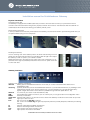
Installation manual for Schleifenbauer Gateway
Physical installation
Connecting power lead
The Gateway is equipped with a Wieland (GST18/3) connector at the rear side. Connect your power lead to the the
connector and make sure that the fixing hook is properly hooked in the connector. This will ensure that the cable will not
accidentally be disconnected, thus leaving your Gateway without power.
Disconnecting power lead
In case you need to disconnect the power lead from the Gateway, use a flat screw driver to push the fixing aside. Now you
can pull the Wieland plug out of its receptacle.
Mounting the Gateway
The 19” mounting ‘ears’ of the Gateway have 3 off-centre holes for fixing to the 19”
panels. The off-centre holes ensure that you will always find the right hole to adjust
the Gateway so that no space in your cabinet is wasted.
Before fixing the PDU to the panel mounts check which of the 3 holes fits to a 19”
panel hole. Fix a cage nut (if needed) and bolt the PDU to the 19” panel mount with
1 bolt to each side.
Gateway interfaces
Overview of the Gateway connections:
data bus!
Starting point for Schleifenbauer data bus. From here you connect a standard CAT5 cable to the 1st
Schleifenbauer PDU.
close ring! (optional) Termination point of the Schleifenbauer data bus. If you terminate the data bus, by installing a CAT5
cable between the last unit on the bus and this port, you have created a ring. This will offer redundancy
against a single disconnection in the data bus. (available through software update late Q1 '09)
ethernet!
To connect to your TCP/IP Local Area Network (LAN)
USB !
Use a USB printer cable to connect to your PC. Via this port you can get access to the configuration menu
RS232!
Currently not activated
setup reset! Hold the reset button for 15 seconds to force a reset of the Gateway. Continue to hold to enter set-up mode
error !
Lights up in case of an error
Port"
OFF: Rx and TX via data bus connector
ON: Rx and TX via close ring (if it lights very frequently: data bus possibly disrupted, otherwise just checking
the ring )
Tx!
Transmit. Data being transmitted over data bus
Rx!
Receive. Data being received over data bus
Link!
Lights up blue if the LAN connection is OK
Act!
Lights up blue when data is transmitted
Schleifenbauer Products Gateway Installation manual V0.5 © 2009
TCP/IP setup
Connect your Gateway to the TCP/IP network (LAN). By default the Gateway is set up to obtain an IP-address from your
DHCP server on your LAN. Power up your Gateway after connecting the Gateway to your LAN with a standard CAT5 (or
better) cable.
Connect the supplied USB cable to the USB port of the Gateway and the USB port of your computer. If the USB serial driver
is not yet installed on your computer it will look for it automatically. Make sure that your computer is connected to the
Internet.
Open Hyperterminal with settings 19200-8-N-1 (none) and boot the Gateway by pressing the reset button and hold for 15
seconds. You might see a screen like this one:
The Gateway will show what IP address has been assigned to it. If you need to work with fixed IP-address you need to
reboot the Gateway and hold the reset button until you are asked to release. The Gateway will start a self-test procedure
after which you need to press the reset button one more time to enter the Set-Up menu as shown below:
Follow the instruction in the Hyperterminal window to set-up a fixed IP-address.
You can now enter the IP-address in your web browser to get access to the Gateway (default user = power, no password.
Please change asap !)
See the Operations Manual for more detailed information on the Gateway.
Schleifenbauer Products Gateway Installation manual V0.5 © 2009