1
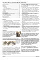
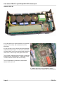
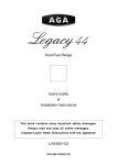
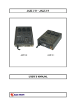
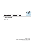
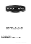
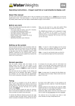
IMC788-LD+, Quad 5 Amp DMX-512 dimmer pack
A publication of
CDS advanced technology bv,
Maassluis, The Netherlands
Copyright 2004 CDS advanced technology bv
August, 2004
All rights reserved. This document may not, in whole or in part, be copied, photocopied, reproduced, translated,
or reduced to any electronic or machine readable form without prior consent, in writing, from CDS advanced
technology bv.
The supplied material, hardware and software, is intended for use only as described in the manuals. Use of
undocumented features or parameters may cause damage and unpredictable results for which CDS advanced
technology bv can not assume responsibility. Although every effort has been made to make the supplied
material and its documentation as accurate and functional as possible, CDS advanced technology bv will not
assume responsibility for any damage incurred or generated by such material. CDS advanced technology bv
reserves the right to make improvements and changes in the product described in this manual at any time
without notice.
LanBox-LC and 788-LD are trademarks of CDS advanced technology bv.
User manual 788-LD+, quad 5 Amp DMX-512 dimmer pack
Table of Contents................................................... 2
Features.................................................................. 2
Installation..............................................................2
Test mode........................................................... 2
DMX channel selection...................................... 2
Connecting the 788-LD+ to a DMX controller......2
Notes...................................................................2
Operation................................................................3
Channel modes.......................................................3
Overload and short circuit protection.................... 3
DMX indication..................................................... 3
Technical specifications.........................................3
CE and FCC declarations.......................................3
Safety instructions..................................................3
Inside the 788-LD+................................................ 4
Features
• Four independent dimmer / switch channels, each
channel up to 5 Amp output.
• 5 pole XLR connectors, conform USITT DMX.
• 0 to 100% dimming or on/off switching channels.
• Controllable by any DMX-512 light controller such
as the LanBox-LC
• Short circuit and overload protected without fuses.
• Suited for inductive, ordinary and halogen loads.
• Complies to “Isolated DMX512-A” and DMX-512
USITT 1990.
Installation
The 788-LD+ can be placed on floor or
mounted on a truss with the included
hook and loop straps. Always use the
included safety cord when mounting
on a location where it could be
potentially hazardous!
Connect your lamps with the included GST18-3
connectors, and connect the mains cable to a 16 amp
fused main connection with safety ground. Be sure the
main voltage is
between 100
and 240 Volt,
50 or 60 Hz.
step 1
step 2
Note: The LED display is normally off. When you
press one of the buttons, the base DMX address
and channel temperatures (in tens of degrees
Celsius) is shown.
Note: The intensity of the display depends on the
number of characters shown, and the main voltage.
Note: The 788-LD+ has isolated DMX connections,
so you don’t have to worry about ground loops. Be
sure that the shield of the DMX cable is ONLY
connected to pin 1 of the XLR (NOT to the
housing, ground of the XLR).
step 3
At the front end of the 788-LD+, a LED display and
two buttons can be found. Press a button for at least 3
seconds so that the displayed DMX address starts
blinking. Set the address to 0, so the pack enters the
test mode. Your lamps should fade in and turned off
one by one. After this test set the DMX address of the
pack e.g. to 1. You should now be able to use the
channels A, B, C and D by setting DMX channels 1-4
on your DMX controller.
Page 2
Connecting the 788-LD+ to a DMX controller
To connect the 788-LD+ to your DMX controller, take
the following steps:
• Connect the data output of your DMX controller to
the DMX input of the 788-LD using 5-pin XLR
cable, which is standard DMX cable. Possibly your
DMX controller has a 3-pin XLR data output in
which case you should use a cable that adapts from
3- to 5-pin XLR.
• If you are using only one 788-LD+, insert a
termination plug into the DMX output connector of
the dimmer pack.
• If you are using more than one DMX device,
connect the data output of each device to the data
input of the next device. The order in which the
devices are connected together is not important so
the most efficient cabling route may be used. Plug a
XLR termination plug into the last DMX device in
the link.
• Possibly you want to connect 3-pin and 5-pin DMX
devices together in one link. In that case you should
adapt from 3- to 5-pin XLR or from 5- to 3-pin
XLR.
• Check the DMX activity indication indicator on the
788-LD+, this is the rightmost decimal point on the
display, and if available a DMX activity indication
LED on the DMX controller. These indicators
should flicker vaguely providing that the controller
is active. If the indication LED is constantly off or
constantly on, your cabling is not correct.
Note: Mains cable colouring in Europe is:
L = Brown, N = Blue, Ground = Green-yellow
Tip: Obtain USITT publication “Recommended
Practice for DMX512”, as it contains very useful
information about DMX installations.
788-LD+
User manual 788-LD+, quad 5 Amp DMX-512 dimmer pack
Operation
A DMX controller can select the dimming percentage
of each output. The selected DMX base channel
number plus 3 subsequent DMX channels are
occupied by the 788-LD+. The dimmer outputs will
go to the dimming percentage selected by the DMX
controller immediately after the DMX controller
modifies this setting. The DMX values 0-255
represents 100-0% dimming, or 0-100% intensity.
Channel modes
Default all four channels of the 788-LD+ are in
dimming mode, but there are 4 operating modes for
each channel, namely: Dim, Switch, Off and On. The
mode can be set by pressing both buttons for at least 3
sec. The plus button can then be used to select
between the channels, while the minus button toggles
between the modes.
Overload and short circuit protection
When the 788-LD+ senses a short circuit situation, all
outputs are switched off immediately and the display
shows a blinking “S”. When a channel becomes
overloaded, the output is switched off and the display
shows a blinking channel letter (a, b, c or d). After the
overload situation has been solved, normal operation
will resume after the 788-LD+ internal temperature
drops below the critical value. An short circuit
condition is detected if a current of more than 100 A
flows for some short period of time. This mechanism
provides an adequate short circuit protection.
However, when switching on cold lights, a current
equal to approximately 10 times the regular current
will flow for a short period of time. This means that
when switching on 4 lights of 1 kW (at 230V) , a
current of approx. 4 x 40 = 160 Amp will flow,
causing the protection mechanism to detect a short
circuit. All outputs will be switched off. To avoid this
problem, set the lights to the least possible output
setting, thus almost maximal dimmed, the lights will
be warmed continuously.
DMX indication
The green rightmost decimal dot of the display
indicates DMX activity and may be helpful searching
for problems in DMX cabling or connection. In an
erroneous situation, the green dot is off or lights at an
alarming fierceness. Possible problems in the DMX
cabling are: bad connections, short-circuits or twisted
polarity of the DMX signals.
788-LD+
Technical specifications
Power supply: 100-240 Vac ; 50/60 Hz ; 16A
Ambient temperature: 0...+40 Degrees Celsius
Humidity: 30...90% RH
Dimensions: 205 x 105 x 56 mm
Output per channel: max. 5A, @25ºC
This device complies with the European low voltage
directive and the European EMC directive according
to the following standards:
Electrical safety: EN 60950: 2002
Emission: EN 55015: 2000 + A1: 2002 + A2: 2002
Immunity: EN-IEC 61000-6-2: 2001
Due to low frequency harmonics and heavy load
fluctuations one must have official approval of the
authorities to use this professional device. on a public
main supply.
FCC
This equipment has been tested and found to comply
with the limits for a class A digital device, pursuant to
Part 15 of the FCC Rules. These limits are designed to
provide reasonable protection against harmful
interference when the equipment is operated in a
commercial environment. This equipment generates,
uses, and can radiate radio frequency energy and, if
not installed and used in accordance with the
instruction manual, may cause harmful interference to
radio communications. Operation of this equipment in
a residential area is likely to cause harmful
interference in which case the user will be required to
correct the interference at his own expense.
Safety instructions
• The 788-LD+ is grounded through the power cord.
To avoid electric shock, connect the power cord
into a properly wired receptacle where earth ground
has been verified by a qualified service person.
• To avoid personal injury and warrant proper
operation, do not remove covers or panels from the
788-LD+.
• Do not use the 788-LD+ in humid, more then 90%
RH environments.
• If the 788-LD+ must be mounted on a location
where it could be potentially hazardous if the
connection would get loose, additional
precautionary measures should be taken; Use the
included safety cord!
Page 3
User manual 788-LD+, quad 5 Amp DMX-512 dimmer pack
Inside the 788-LD+
As we do not advice to open the dimmer, we provided
a picture of the inside, and a detail picture of the
electronics.
As you can see it’s very compact, and there have been
used advanced techniques. Like the black potted filter
coils are cooled, by using very special heat conducting
foam, which is also on top of the green transformer.
The coil heat is transferred to the housing via the foam
and a aluminium strip beneath it. A same type of strip
is used to transfer the triac heat to the housing.
The coil temperature is measured by temperature
sensors below each coil.
A modern single chip micro computer is used to
control the triacs, and to handle DMX and the display.
Page 4
788-LD+