1
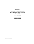
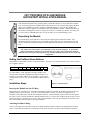
2577 PROFIBUS DP SLAVE MODULE
QUICKSTART INSTALLATION MANUAL
PROFIBUS
DP
SLAVE
ACTIVE
C
P
XM T R CV
This document describes how to properly unpack, install and configure a CTI 2577 DP Slave module.
The CTI 2577 Profibus Slave Module enables a Siemens® S7 (or any controller that supports Profibus
DP) to access SIMATIC® 505 PLC memory as standard analog I/O. Using the 2577 module, the
SIMATIC® 505 PLC appears as a standard I/O drop on the Profibus network. Additional literature for
this product, including the Installation and Operation Guide, is available on both the CTI Catalog and
Technical Library CDROM and on the CTI web site (http://www.controltechnology.com).
Unpacking the Module
CONFIG
PR OFIBU S
DP
2 57 7
Open the shipping carton and remove the special anti-static bag that contains the module. After
discharging any static build-up, remove the module from the static bag. Do not discard the static bag.
Always use this bag for protection against static damage when the module is not inserted into the I/O
base.
CAUTION:
The components on the module can be damaged by static electricity discharge. To prevent this
damage, the module is shipped in a special anti-static bag. Static control precautions should be
followed when removing the module from the bag and when handling the printed circuit card during
configuration.
Setting the Profibus Slave Address
Switchblock 1 on the module is used to set the slave address. See Figure 1 for location of SW1. The switches on SW1
are weighted as follows:
Switch
Weight
1
N/A
2
64
3
32
4
16
5
8
6
4
7
2
8
1
To set the address, set the appropriate switches on SW1 to the
closed position so that the weighted total equals the address. For
example, to set Profibus address 26, set switches 4, 5, and 7 to the
closed position (16+8+2 = 26). See the Profibus Address Table on
page 3.
Installation Steps
Figure 1. Switch Location
Inserting the Module into the I/O Base
Ensure that power to the base is off. Hold the top and bottom of the bezel and slide the module carefully into the slot,
pushing it all the way into the base. If you have inserted the module correctly, you will feel a slight increase in
resistance as the module mates with the base backplane connector. Once the module is fully seated in the slot, tighten
the captive screws at the top and bottom to hold the module in place. To remove the module from the I/O base, remove
power from the base, loosen the captive screws, and extract the module. Take care not to damage the connector at the
back of the module when inserting or removing the module.
Attaching Profibus Cabling
Connect your Profibus network cable connector to module Profibus connector and secure by tightening the retaining
screws. Ensure that the termination switch in the network cable connector is set to the proper termination position.
2577 QuickStart Installation Manual (P/N 062-00319-011) 12/29/05
Page 1
Power Up
After you apply power to the base, the ACTIVE indicator will flash. The ACTIVE indicator will remain flashing until
the module is online with the Profibus master. The Profibus XMT and RCV indicators will illuminate when the module is
communicating with the Profibus master. Once the module is online, the ACTIVE indicator will be on solid.
If you are replacing an existing module, this completes the installation process.
Additional Installation Steps – First Time Installation
If you are installing a module for the first time, you will need to configure the 505 I/O to include the module. You will
also need to define the module to the Profibus controller using the appropriate configuration tool, such as Step 7 or
COM Profibus.
Configuring the 505 PLC I/O
The 2577 logs in as a Special Function module with 2 WX and 6 WY words. To view the PLC I/O configuration chart,
refer to your SIMATIC® 505 programming software manual. For the particular slot that contains the module, ensure
that the slot entry indicates 2 WX and 6 WY and that Special Function = Yes. Set the module address to match your
specific 505 PLC requirements.
Profibus Configuration
The module may be configured using standard Profibus configuration software such as COM Profibus or Step 7. Using
the Profibus configuration software, you will need to perform the following steps:
•
Install the GSD file in the software. The 2577 GSD file may be downloaded from the CTI web site
http://www.controltechnology.com/downloads505.htm
•
Add the 2577 module to the Profibus network configuration.
•
Configure the 2577 module I/O word size by picking a module configuration that suits your application.
Configurations supported include 1 in/1 out, 2 in/2 out, 4 in/4 out, 8 in/8 out, 16 in/16 out, 32 in/32 out, 64 in/64
out, and 110 in/110 out.
•
Select the Profibus Address that will be used by the module.
•
Select the module parameters
- Input Data Type: Select V, WX, X, or C. (X and C are available for sizes 1, 2, 4, 8, or 16 only).
- Input Address: Enter the address of the 505 PLC memory block that will be read by the Profibus
controller.
- Output Data Type: Select V or C (C is available for sizes 1, 2, 4, 8, or 16 only).
- Output Address: Select the address of the 505 PLC memory block that will be written by the Profibus
controller.
•
Download the configuration to the Profibus master.
Note:
Make sure that the address you select is actually available on the SIMATIC® 505 PLC. If any address within the block
is out of range, the module will set the Profibus error bit and the master will not read or write the SIMATIC® 505 PLC.
Caution:
The entire block of data words with the starting address and size you selected in I/O size will be written by the
Profibus controller. Make sure that you are not inadvertently overwriting data used for other PLC functions.
If the module does not go online with the Profibus Master, you probably have an error in setting the Profibus Slave
address or an error in configuring the module using the Profibus software (Step 7 or COM Profibus). See the 2577
Profibus Slave Module Installation and Operation Guide for troubleshooting tips. If you do not have a copy, you may
download it from the CTI Web site http://www.controltechnology.com/manuals505.htm .
Page 2
2577QuickStart Installation Manual
Profibus Address Table
Address
1
2
3
4
5
6
7
8
9
10
11
12
13
14
15
16
17
18
19
20
21
22
23
24
25
26
27
28
29
30
31
32
33
34
35
36
37
38
39
40
41
42
43
44
45
46
47
48
49
50
51
52
53
54
55
56
57
58
59
60
61
62
63
1
2
3
Switch
4 5 6
7
X
X
X
X
X
X
X
X
X
X
X
X
X
X
X
X
X
X
X
X
X
X
X
X
X
X
X
X
X
X
X
X
X
X
X
X
X
X
X
X
X
X
X
X
X
X
X
X
X
X
X
X
X
X
X
X
X
X
X
X
X
X
8
X
X
X
X
X
X
X
X
X
X
X
X
X
X
X
X
X
X
X
X
X
X
X
X
X
X
X
X
X
X
X
X
X
X
X
X
X
X
X
X
X
X
X
X
X
X
X
X
X
X
X
X
X
X
X
X
X
X
X
X
X
X
X
X
X
X
X
X
X
X
X
X
X
X
X
X
X
X
X
X
X
X
X
X
X
X
X
X
X
X
X
X
X
X
X
X
X
X
X
X
X
X
X
X
X
X
X
X
X
X
X
X
X
X
X
X
X
X
X
X
X
X
X
X
X
X
X
X
X
X
Address
64
65
66
67
68
69
70
71
72
73
74
75
76
77
78
79
80
81
82
83
84
85
86
87
88
89
90
91
92
93
94
95
96
97
98
99
100
101
102
103
104
105
106
107
108
109
110
111
112
113
114
115
116
117
118
119
120
121
122
123
124
125
126
127
1
2
X
X
X
X
X
X
X
X
X
X
X
X
X
X
X
X
X
X
X
X
X
X
X
X
X
X
X
X
X
X
X
X
X
X
X
X
X
X
X
X
X
X
X
X
X
X
X
X
X
X
X
X
X
X
X
X
X
X
X
X
X
X
X
X
3
Switch
4 5 6
7
8
X
X
X
X
X
X
X
X
X
X
X
X
X
X
X
X
X
X
X
X
X
X
X
X
X
X
X
X
X
X
X
X
X
X
X
X
X
X
X
X
X
X
X
X
X
X
X
X
X
X
X
X
X
X
X
X
X
X
X
X
X
X
X
X
X
X
X
X
X
X
X
X
X
X
X
X
X
X
X
X
X
X
X
X
X
X
X
X
X
X
X
X
X
X
X
X
X
X
X
X
X
X
X
X
X
X
X
X
X
X
X
X
X
X
X
X
X
X
X
X
X
X
X
X
X
X
X
X
X
X
X
X
X
X
X
X
X
X
X
X
X
X
X
X
X
X
X
X
X
X
X
X
X
X
X
X
X
X
X
X
X
X
X
X
X
X
X
X
X
X
X
X
X
X
X
X
X
X
X
X
X
X
X
X
X
X
X
X
X
X
X
X
x = Closed Switch Position
2577 QuickStart Installation Manual (P/N 062-00319-011) 12/29/05
Page 3
LIMITED PRODUCT WARRANTY
CTI warrants that this CTI Industrial Product shall be free from defects in material and workmanship for a period of one
(1) year after purchase from CTI or from an authorized CTI Industrial Distributor. This CTI Industrial Product will be
newly manufactured from new and/or serviceable used parts which are equal to new in the Product.
Should this CTI Industrial Product fail to be free from defects in material and workmanship at any time during this (1)
year warranty period, CTI will repair or replace (at its option) parts or Products found to be defective and shipped
prepaid by the customer to a designated CTI service location along with proof of purchase date and associated serial
number. Repair parts and replacement Product furnished under this warranty will be on an exchange basis and will be
either reconditioned or new. All exchanged parts or Products become the property of CTI. Should any Product or part
returned to CTI hereunder be found by CTI to be without defect, CTI will return such Product or part to the customer.
This warranty does not include repair of damage to a part or Product resulting from: failure to provide a suitable
environment as specified in applicable Product specifications, or damage caused by an accident, disaster, acts of God,
neglect, abuse, misuse, transportation, alterations, attachments, accessories, supplies, non-CTI parts, non-CTI repairs or
activities, or to any damage whose proximate cause was utilities or utility like services, or faulty installation or
maintenance done by someone other than CTI.
Control Technology Inc. reserves the right to make changes to the Product in order to improve reliability, function, or
design in the pursuit of providing the best possible Product. CTI assumes no responsibility for indirect or consequential
damages resulting from the use or application of this equipment.
THE WARRANTY SET FORTH ABOVE IN THIS ARTICLE IS THE ONLY WARRANTY CTI GRANTS AND IT
IS IN LIEU OF ANY OTHER IMPLIED OR EXPRESSED GUARANTY OR WARRANTY ON CTI PRODUCTS,
INCLUDING WITHOUT LIMITATION, ANY WARRANTY OF MERCHANTABILITY OR OF FITNESS FOR A
PARTICULAR PURPOSE AND IS IN LIEU OF ALL OBLIGATIONS OR LIABILITY OF CTI FOR DAMAGES IN
CONNECTION WITH LOSS, DELIVERY, USE OR PERFORMANCE OF CTI PRODUCTS OR INTERRUPTION
OF BUSINESS, LOSS OF USE, REVENUE OR PROFIT. IN NO EVENT WILL CTI BE LIABLE FOR SPECIAL,
INCIDENTAL, OR CONSEQUENTIAL DAMAGES.
SOME STATES DO NOT ALLOW THE EXCLUSION OR LIMITATION OF INCIDENTAL OR
CONSEQUENTIAL DAMAGES FOR CONSUMER PRODUCTS, SO THE ABOVE LIMITATIONS OR
EXCLUSIONS MAY NOT APPLY TO YOU.
THIS WARRANTY GIVES YOU SPECIFIC LEGAL RIGHTS, AND YOU MAY ALSO HAVE OTHER RIGHTS
WHICH MAY VARY FROM STATE TO STATE.
This manual is published by Control Technology Inc., 5734 Middlebrook Pike, Knoxville, TN 37921. This manual
contains references to brand and product names which are tradenames, trademarks, and/or registered trademarks of
Control Technology Inc. Siemens® and SIMATIC® are registered trademarks of Siemens AG. Other references to
brand and product names are tradenames, trademarks, and/or registered trademarks of their respective holders.
Page 4
2577QuickStart Installation Manual