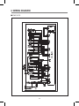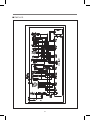
1
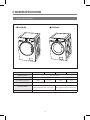
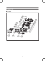
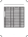
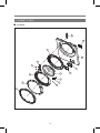
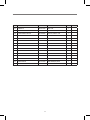
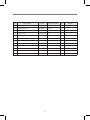
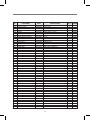
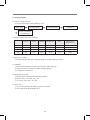
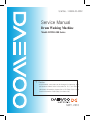
S/M No. : DWDLD14002
Service Manual
Drum Washing Machine
Model: DWD-L100 Series
?
Caution
: In this Manual, some parts can be changed for improving, their
performance without notice in the parts list. So, if you need the
latest parts information, please refer to PPL(Parts Price List) in
Service Information Center (http://svc.dwe.co.kr).
MAY. 2010
DRUM WASHING MACHINE
SERVICE MANUAL
1. WHAT IS DRUM WASHING MACHINE?.......................................1
2. WASHER SPECIFICATION...........................................................2
3. PARTS LIST BY ASS'Y..................................................................4
4. CONTROL PART FUNCTION SPECIFICATION.........................23
5. ELECTRONIC FIELD PARTS LIST AND SPECIFICATION........38
6. WIRING DIAGRAM......................................................................39
1. WHAT IS DRUM WASHING MACHINE?
1. Drum Washing Machine
Water consumption is reduced by using the power of the laundry falling (free-fall) created when rotating
the drum. With temperature control system, this drum washing machine saves energy and improves
washing performance at the same time. 2. Key Features
◈ Waist Care
Designed by the waist, and the most comfortable
angle eject into the laundry is convenient and easy to
manipulate.
◈ DD inverter motor
The direct-drive type of which motor is directly
connected to drum without an interim clutch,
significantly reduces noise and vibration.
◈ Star Drum
Using Star Drum is able to show users higher
Washing Performance and Minimal damage of
laundry, water consumption.
◈ Self-Cleaning Course of Drum.
Enables the machine to do Self-Cleaning of Drum.
◈ Digital Condensing Dry System.
Condensing Dry System with saveing energy.
◈ Luxury Audio Dial
Using the advanced Audio Dial is luxury design of
exterior.
1
3. Power System
LAUNDRY
BLDC
Pump Drainage
• DD Control: Direct drive type of direct connection between drum and motor
• Rotation by powerful high-performance BLDC motor
2
2. WASHER SPECIFICATION
1. Product Specification
■ 1st Model
■ 2st Model
MODEL
DWC-LU1011/1211 DWD-LU1011/1211 DWC-LD1411/1611 DWD-LD1411/1611
Dimension (mm)
600 X 645 X 850
Maximum mass of textile (kg)
9 Kg
Unit Weight (net/gross)
78/82
71/75
Standard Water Consumption
Spin Speed (RPM)
Operating Water Pressure
76/80
69/73
65 ℓ
DWC(DWD)-LU10XX : MAX 1000
DWC(DWD)-LU12XX : MAX 1200
DWC(DWD)-LD14XX : MAX 1400
DWC(DWD)-LD16XX : MAX 1600
0.03MPa ~ 0.8MPa (0.3kgf/cm2 ~ 8kgf/cm2)
3
3. PARTS LIST BY ASS'Y
1. PANEL AS
■ 1st Model
A09-7
A09-6
A11
A09-0
A14
A10
A09-2
A09-3
A09-5
A13
A09-1
A09-4
A01
A02
A08
A15
A04
A03
A07
A16
A05
A06
4
No.
PARTS NAME
CODE
SPECIFICATIONS
Q’TY
A01 PANEL *F
36142T2000
ABS
1
A02 DECORATOR WINDOW COURSE
3611696000
ABS
1
A03 WINDOW COURSE
3615509200
C-LU1011
1
A04 DECORATOR WINDOW DISPLAY
3611696100
ABS
1
A05 BUTTON FUNCTION
3616644000
ABS
1
A06 BUTTON PS
3616644100
ABS
1
A07 WINDOW DISPLAY
3615509300
C-LU1011
1
A08 BUTTON LED
3616644200
C-LU1011
1
REMARK
A09 PCB AS
PRPSSWL010 1ST FRONT PCB AS (LD10/LU10)
1
EC
PCB AS
PRPSSWL011 1ST FRONT PCB AS (LD12/LU12)
1
EC
PCB AS
PRPSSWL012 1ST FRONT PCB AS (LD14)
1
EC
PCB AS
PRPSSWL013 1ST FRONT PCB AS (LD16)
1
EC
PCB AS
PRPSSWL000 1ST FRONT PCB AS (LD10/LU10)
1
STANDBY 1W
PCB AS
PRPSSWL001 1ST FRONT PCB AS (LD12/LU12)
1
STANDBY 1W
PCB AS
PRPSSWL002 1ST FRONT PCB AS (LD14)
1
STANDBY 1W
PCB AS
PRPSSWL003 1ST FRONT PCB AS (LD16)
1
STANDBY 1W
A09-0 PCB BOARD
3614347000
L SERIES FRONT PCB BOARD
1
A09-1 CUSTOM LED
3613058300
C-LU1011
1
A09-2 LED LAMP
DS0302WP--
9MM FORMING TYPE , D=3MM
36
A09-3 SW TACT
5S50101402
2PIN, 6*6*5
9
A09-4 HOLDER LED OPTION
3613058000
HIPS
1
A09-5 HOLDER LED FUNCTION
3613058100
HIPS
1
A09-6 HOLDER LED COURSE
3613058200
HIPS
1
A09-7 CASE PCB F
36111T1N00
HIPS
1
A10 BUTTON DIAL OUTER
3616643800
ABS
1
A11 BUTTON DIAL INNER
3616643900
ABS
1
A12 CASE DETERGENT AS
36111T1P00
A13 CASE DETERGENT
36111T1J00
PP
1
A14 CAP SOFTENER
3610916600
PP
1
A15 CASE HANDLE
3611149200
ABS
1
A16 DECORATOR CASE HANDLE
3611696200
ABS
1
5
1
2. PANEL F AS
■ 2st Model
A05-2
A05-3
A05-4
A05-1
A06
A07
A05-0
A05
A08
A04
A09
A03
A02
A01
A13
A12
A11
A10
6
No.
PARTS NAME
CODE
SPECIFICATIONS
Q’TY
REMARK
4x16 SUS 430
A01
PANEL FRONT
36142T2100
ABS
2
A02
BUTTON FUNCTION
3616644400
ABS
1
A03
BUTTON OPTION
3616644700
ABS
1
A04
HOLDER LED FUNCTION
3613058500
HIPS
1
A05
PCB AS
PRPSSWL060
2nd FRONT PCB AS (LD10/LU10)
1
EC
PCB AS
PRPSSWL061
2nd FRONT PCB AS (LD12/LU12)
1
EC
PCB AS
PRPSSWL062
2nd FRONT PCB AS (LD14)
1
EC
PCB AS
PRPSSWL063
2nd FRONT PCB AS (LD16)
1
EC
PCB AS
PRPSSWL050
2nd FRONT PCB AS (LD10/LU10)
1
STANDBY1W
PCB AS
PRPSSWL051
2nd FRONT PCB AS (LD12/LU12)
1
STANDBY1W
PCB AS
PRPSSWL052
2nd FRONT PCB AS (LD14)
1
STANDBY1W
PCB AS
PRPSSWL053
2nd FRONT PCB AS (LD16)
1
STANDBY1W
A05-0 HOLDER LED DISPLAY
3613058600
ABS
1
A05-1 CASE PCB F
36111T1R00
HIPS
1
A05-2 SCREW TAPPING
7122401611
T2S TRS
1
A05-3 PCB BOARD F
3614348500
FR-1
1
A05-4 HOLDER LED COURSE
3613058400
HIPS
1
A06
BUTTON DIAL
3616644300
ABS
1
A07
DECORATOR BUTTON DIAL
3611696400
ABS
1
A08
BUTTON START
3616644600
ABS
1
A09
BUTTON POWER
3616644500
ABS
1
A10
DECORATOR FILM
3611696500
P.C FILM
1
A11
WINDOW COURSE
3615509400
TR-ABS
1
A12
SCREW TAPPING
7122401608
T2S TRS
1
A13
CASE DETERGENT AS
36111T1P10
PP
1
7
4x16 MFZN
CHROMIUM CILDING
3. INLET BOX AS
B10
B12
B06
B14
B13
B09
B07
B01
B08
B11
B04
B02
B05
B03
8
No.
PARTS NAME
CODE
SPECIFICATIONS
Q’TY REMARK
B01
NOZZLE *T
3618111100
PP
1
B02
NOZZLE *U
3618111000
PP
1
B03
BOX INLET
3610526500
PP
1
B04
HOSE INLET
3613274600
EPDM
1
B05
CLAMP AS
3611203200
ID=60, WIRE+GUIDE+BOLT+NUT
1
B06
VALVE INLET
36154L3A00
220-240V.VDE.BITRON.4WAY V1:DRY V2:STEAM
1
VALVE INLET
36154L3B00
220-240V.VDE.BITRON.3WAY V2:STEAM
1
VALVE INLET
36154L3D10
120V.BITRON.4WAY V1:DRY V2:STEAM
1
VALVE INLET
3615414900
220-240V 2-WAY PP/BRACKET
1
VALVE INLET
3615415050
220~240V,3WAY,RINSE GUIDE,PP/BRACKET
1
VALVE INLET
3615416820
220-240V.VDE.BITRON.2WAY
1
VALVE INLET
3615416821
220-240V.VDE.BITRON.2WAY + DR TECH INSPECTION COST
1
VALVE INLET
3615416720
220-240V60HZ.VDE.BITRON.1WAY
1
VALVE INLET
3615416970
UL 220~240V,BITRON 3WAY V1,V3 WITH CONTROL PC
1
B07
HOSE WATER SUPPLY
3613270900
EPDM ID9.5 OD14.5, WASHING
1
B08
HOSE WATER SUPPLY
3613270900
EPDM ID9.5 OD14.5, PRE.WASH
2
B09
CLAMP HOSE
3611205800
100H, ID=13.8 W=10.0 0.9T
10
B10
VALVE INLET
3615414800
220-240V 1-WAY HOT PP-BRACKET
1
VALVE INLET
3615414820
220-240V 1-WAY HOT PP-BRACKET 180
1
VALVE INLET
3615415700
100-130 1-WAY HOT PP-BRACKET
1
B11
HOSE WATER SUPPLY
3613270900
EPDM ID9.5 OD14.5, HOT
1
B12
HOSE WATER SUPPLY
3613270900
EPDM ID9.5 OD14.5, STEAM
1
PIPE JOINT I
3614426000
PP
1
PIPE JOINT(HOSE INLET)
3614413300
PP , T-type
1
Unit Steam AS
36189M2U00 L-SERIES STEAM UNIT 900W
B13
B14
9
1
option
4. CABINET F ASSY
■ 1st Model
C03
C02
C10
C01
C11
C12
C14
C13
C06
C07
C08
C05
C09
C04
10
C15
No.
PARTS NAME
CODE
SPECIFICATIONS
Q’TY REMARK
C01
CABINET *F
3610814000
SECD 0.8T
1
C02
SWITCH DOOR LOCK
3619047200
DL-S1.250V16A.BITRON
1
C03
PLATE HINGE SUPPORT
3614539800
SPG 0.8T, DWD-T110R
1
C04
FRAME DOOR *O
36122UD800
ABS
1
C05
PROTECTOR GLASS
3618345500
ABS
1
C06
DECORATOR DOOR *O
3611695900
ABS
1
C07
HOOK DOOR
3613100900
ZNDC
1
C08
SPRING HOOK
3615115400
SUS304,
1
C09
HOOK SHAFT
3613101000
SUS, D=3.0
1
C10
FRAME DOOR *I
36122UD600
PP
1
C11
HINGE DOOR
3612903800
AL, DWD-T110R
1
C12
CAP HINGE DOOR
3610916500
POM
4
C13
DOOR GLASS
361A113300
GLASS
1
C14
CASE PUMP AS
36111T1K10
CASE PUMP(PP)+PAD
1
C15
COVER PUMP
3611431500
ABS
1
11
5. DOOR AS
■ 2st Model
C01
C02
C03
C04
C05
C12
C11
C06
C10
C07
C09
C08
12
No.
PARTS NAME
CODE
SPECIFICATIONS
Q’TY
C01
FRAME DOOR 0
36122UDC00
ABS
1
C02
PROTECTOR GLASS
3618345600
TR-ABS
1
C03
DOOR GLASS
361A113300
GLASS
1
C04
FRAME DOOR 1
36122UDD00
PP
1
C05
HINGE DOOR
3612903800
ALDC
1
C06
CAP HINGE DOOR
3610916500
POM
4
C07
SCREW TAPPING
7115402029
T1S FLT
14
C08
HOOK DOOR
3613100900
ZNDC
1
C09
SPRING HOOK
3615115400
SUS
1
C10
HOOK SHAFT
3613101000
SUS
1
C11
CASE SPRING DOOR
3611149300
ABS
1
C12
SCREW TAPPING
7122401611
T2STRS
2
13
REMARK
4*20 STS430 NATURE
4*6 MFZN
6. TUB ASSY(UNIVERSAL)
D26
D24
D09
D10
D23
D22
D25
D21
D08
D06
D20
D19
D50
D07
D18
D05
D17
D04
D14
D16
D12
D49
D15
D48
D11
D13
D03
D02
D39
D42
D47
D43
D40
D01
D44
D38
D45
D41
D46
D30
D37
D36
D28
D35
D34
D27
D29
14
D31
D32
D33
No.
D01
D02
D03
D04
D05
D06
D07
D08
D09
D10
D11
D12
D13
D14
D15
D16
D17
D18
D19
D20
D21
D22
D23
D24
D25
D26
D27
D28
D29
D30
D31
D32
D33
D34
D35
D36
D37
D38
D39
D40
D41
D42
D43
D44
D45
D46
D47
D48
D49
D50
PARTS NAME
BALANCER WEIGHT L
SPECIAL SCREW
BALANCER WEIGHT R
CLAMP GASKET AS
GASKET
GASKET
NOZZLE SHOWER
CLAMP GASKET BUSHING
SPECIAL SCREW
DUCT B AS
HOSE DRAIN *I
CLAMP AS
CLAMP HOSE
CLAMP HOSE
AIR TRAP
HOSE AIR(PRESSURE)
DAMPER FRICTION
DAMPER PIN
TUB *F (FRONT)
SPRING SUSPENSION
SPECIAL SCREW
SPECIAL SCREW
LIFTER WASH
SCREW TAPPING
DRUM SUB AS
SPIDER AS
WATER SEAL
SEALING TUB
FIXTURE HEATER
BEARING INNER
UNIT MOTOR UNIVERSAL
BALANCER WEIGHT LOWER
SPECIAL SCREW
SPECIAL SCREW
DAMPER FRICTION
DAMPER PIN
TUB REAR AS
BALANCER WEIGHT T
BALANCER WEIGHT T(WASH)
SPECIAL SCREW
CLAMP HOSE
SPECIAL SCREW
UNIT BUBBLE PUMP AS
HOSE VENT
BEARING OUTER
HEATER WASH
PIPE DUCT AS
PULLEY
SPECIAL BOLT AS
BELT V
CODE
3616110600
3616029400
3616110500
3611207000
3612325300
3612325400
3618111200
3611206800
3616029810
3610DUTL00
3613275200
3611203210
3611204700
3611201401
361A500101
3613266930
361A700110
361A700200
3618830000
3615116800
3616029800
3616029500
361A401300
7122401408
3617012600
361A301200
361A600100
3612321601
3612006700
3616303100
36189L4H10
3616110300
3616029400
3616062800
361A700130
361A700200
36100T1400
3616110400
3616110700
3616029400
3611204700
3616007400
36189L4120
3613267100
3616303200
3612803700
3614414001
3618434100
3616029600
3616591120
SPECIFICATIONS
PP, D-LU1011, 6.6KG
SWCH 8.5X30
PP, D-LU1011, 6.6KG
C-LU1011
EPDM , WASH , D-LU1011
EPDM , DRY , C-LU1011
PP
GI 1.2T
SWCH 6.5X45
C-L E
EPDM D-LU1011
ID=61, WIRE+GUIDE+BOLT, GS
D26
HSW3,YW,D2.6,ID36,W44.5
PP
ID=4,OD=8, L=680MM(L-SERIES)
70N AKS ST=170-260 DL=197.5 LOW NOISE
AKS D=14.5
FRPP, C-LU1011
KGF
SWCH 6.5X30
SUS430 8*25
PP,1PIECE,TWIST
T2S TRS 4X14 SUS,STS
D-LU1011
D-LU1011
NBR
EPDM L1600(-0~ +10)
SUS
6206Z
DC220/50 G&J 2P PI340 45T(CCA)
PP, D-LU1011, 3.5KG
SWCH 8.5X30
SWRCH18A 7.4*25.5
60N AKS ST=170-260 DL=197.5 LOW NOISE
AKS D=14.5
D-LU1011
PP, C-LU1011, 2.48KG
PP, D-LU1011, 2.48KG
SWCH 8.5X30
D26
T2S TRS 4X10+24
220-240V DBK-240DB RP CHSHION
EPDM
6205Z
230V 2000W.1R5A721002.IRCA FUSE 2EA
C-L PIPE DUCT+HOSE+CLAMP
ALDC
SWCH 10*30,F/L BOLT S.P/W SEAL LOCK
GATES 4PJ1175 BUTADIENE RUBBER
15
Q’TY REMARK
1
8
1
1
1
1
1
1
4
1
1
1
1
1
1
1
2
2
1
2
14
3
3
3
1
1
1
1
1
1
1
1
2
2
2
2
1
1
1
2
1
2
1
1
1
1
1
1
1
1
FOR WASH
FOR DRY
FOR DRY
FOR DRY
FOR DRY
FOR WASH
OPTION
OPTION
FOR DRY
7. TUB ASSY(DD MOTOR)
D26
D24
D09
D10
D23
D22
D25
D21
D08
D47
D06
D20
D19
D07
D46
D18
D05
D17
D04
D14
D16
D12
D45
D15
D11
D13
D03
D02
D35
D44
D38
D43
D39
D36
D01
D40
D34
D44-1
D41
D37
D42
D30
D33
D32
D28
D31
D27
D29
16
No.
D01
D02
D03
D04
D05
D06
D07
D08
D09
D10
D11
D12
D13
D14
D15
D16
D17
D18
D19
D20
D21
D22
D23
D24
D25
D26
D27
D28
D29
D30
D31
D32
D33
D33-1
D33-2
D34
D35
D36
D37
D38
D39
D40
D41
D42
PARTS NAME
BALANCER WEIGHT L
SPECIAL SCREW
BALANCER WEIGHT R
CLAMP GASKET AS
GASKET
GASKET
NOZZLE SHOWER
CLAMP GASKET BUSHING
SPECIAL SCREW
DUCT B AS
HOSE DRAIN *I
CLAMP AS
CLAMP HOSE
CLAMP HOSE
AIR TRAP
HOSE AIR(PRESSURE)
DAMPER FRICTION
DAMPER PIN
TUB FRONT
SPRING SUSPENSION
SPECIAL SCREW
SPECIAL SCREW
LIFTER WASH
SCREW TAPPING
DRUM AS
SPIDER AS
WATER SEAL
SEALING TUB
FIXTURE HEATER
BEARING INNER
DAMPER FRICTION
DAMPER PIN
TUB REAR AS
TUB REAR
BEARING HOUSING
BALANCER WEIGHT T
BALANCER WEIGHT T(WASH)
SPECIAL SCREW
CLAMP HOSE
SPECIAL SCREW
UNIT BUBBLE GENERATOR
HOSE VENT
BEARING OUTER
HEATER WASH
HEATER WASH
HEATER WASH
HEATER WASH
D43 PIPE DUCT AS
D44 UNIT STATOR BLDC
UNIT STATOR BLDC
D44-1 HALL IC HOLDER AS
D45 SPECIAL BOLT AS
D46 UNIT ROTOR BLDC
UNIT ROTOR BLDC
D47 SPECIAL BOLT AS
CODE
SPECIFICATIONS
Q’TY
3616110600
3616029400
3616110500
3611207000
3612325300
3612325400
3618111200
3611206800
3616029810
3610DUTL00
3613275200
3611203210
3611204700
3611201401
361A500101
3613266930
361A700110
361A700200
3618830000
3615116800
3616029800
3616029500
361A401300
7122401408
3617012500
361A301200
361A600100
3612321601
3612006700
3616303100
361A700130
361A700200
36100T1400
3618830100
3616305000
3616110400
3616110700
3616029400
3611204700
3616007400
36189L4177
3613267100
3616303200
3612802400
3612802420
3612802440
3612803700
3614414001
36189L6200
36189L620A
3616D01000
3616029900
36189L6300
36189L6300
3616029620
PP, D-LU1011, 6.6KG
SWCH 8.5X30
PP, D-LU1011, 6.6KG
C-LU1011
EPDM , WASH , D-LU1011
EPDM , DRY , C-LU1011
PP
GI 1.2T
SWCH 6.5X45
C-L E
EPDM D-LU1011
ID=61, WIRE+GUIDE+BOLT, GS
D26
HSW3,YW,D2.6,ID36,W44.5
PP
ID=4,OD=8, L=680MM(L-SERIES)
70N AKS ST=170-260 DL=197.5 LOW NOISE
AKS D=14.5
FRPP, C-LU1011
KGF
SWCH 6.5X30
SUS430 8*25
PP,1PIECE,TWIST
T2S TRS 4X14 SUS,STS
D-LU1011
D-LU1011
NBR
EPDM L1600(-0~ +10)
SUS
6206Z
60N AKS ST=170-260 DL=197.5 LOW NOISE
AKS D=14.5
D-LU1011
FRPP, C-LU1011
ALDC, D-LU1011
PP, C-LU1011, 2.48KG
PP, D-LU1011, 2.48KG
SWCH 8.5X30
D26
T2S TRS 4X10+24
HIGH,PAD B,BL/WH,320,RP4,GUIDE O,SPONGE 200
EPDM
6205Z
220V 2KW.1R0A721001.RW8TF.IRCA,NPB
240V 2KW.1R0A721003.RW8TF.IRCA
120V 1KW.1R0A721005.RW8TF1PE.IRCA
230V 2000W.1R5A721002.IRCA FUSE 2EA
C-L PIPE DUCT+HOSE+CLAMP
AL,30T(28T),NMT
AL,DON1300W 30T 36POLE,NMT,PBT
DRUM STATOR PCB HOLDER AS(SVC),NMT
SWCH M8 + SILOCK
L'SERIES, NMT
DON1300W SR-FERRITE12,30~32T,NMT
SWCH 10*30 S/W P/W NON-SEAL LOCK
1
8
1
1
1
1
1
1
4
1
1
1
1
1
1
1
2
2
1
2
14
3
3
3
1
1
1
1
1
1
2
2
1
1
1
1
1
2
1
2
1
1
1
1
1
1
1
1
1
1
1
6
1
1
1
17
REMARK
FOR WASH
FOR DRY
FOR DRY
FOR DRY
FOR DRY
FOR WASH
OPTION
OPTION
~20091211(changed)
20091211~
~20091211(changed)
20091211~
8. DUCT B (for dry model)
E15
E14
E02
E13
E01
E03
E12
E11
E05
E04
E07
E09
E08
E10
18
E06
No.
PARTS NAME
CODE
SPECIFICATIONS
Q’TY REMARK
E01
DUCT B UPPER
361A202400
ALCOSTA
1
E02
SCREW TAPPING
7122401411
T2S TRS 4X14 MFZN
8
E03
SCREW TAPPING
7112401208
T1 TRS 4X12 SUS
1
E04
HEATER DRY
3612801400
230V 2.1KW 25.19OHM 6.1W/SQ INCOLOY800 1R1A034002
1
E05
PACKING THERMOSTAT
3614009900
SILICON, DWD-100DR
1
E05
SWITCH THERMOSTAT
3619046500
ON120°C OFF150°C 230V 15A VDE
1
E06
DUCT B LOWER
361A202500
ALDC C-LU1011
1
E07
BUSHING UPPER
3610703800
POM C-LU1011
4
E08
BUSHING LOWER
3610703900
POM C-LU1011
4
E09
GASKET SEAL A
3612325700
EPDM FOAM, D=5, L=1293
1
E10
PACKING RUBBER
3614009800
SILICON, DWD-100DR
1
E10
THERMISTOR DRY
361AAAAD00 C-LD/LU,L=200,R40=26.065K,R90=4.4278K
1
E11
NUT HEX
3616032100
M6*1.0P,CCW
1
E12
FAN AS
3611886400
GFPP30% , C-LU1011
1
E13
COVER DUCT
3611431400
GFPP30% C-LU1011
1
E14
RING O
3614603400
DWD-100DR,NBR,ID=7.6,OD=13.6
1
E15
UNIT FAN MOTOR
36189M2Q00 24V DC 14W
19
1
9. CABINET AS
F07
F03
F08
F13
F06-1
F06
F06-2
F01
F11
F09
F10
F02
F12
F04
F05
20
No.
PARTS NAME
CODE
SPECIFICATIONS
F01
CABINET
3610813300
F02
FRAME LOWER
36122UD700 SGCC 1.2T
1
F03
FRAME TOP *L
36122UDA00 SGCC 1.6T
1
FRAME TOP *R
36122UDB00 SGCC 1.6T
1
BASE U L
3610393800
SGCC T2.0
1
BASE U R
3610393900
SGCC T2.0
1
F05
LEG ADJUST AS
3617703811
CHINA PARTS, DWD-900W
4
F06
MAIN PCB AS
3610PCBL00 D-LU EFA WASH UNI ZERO REA CC C BB NST
1
MAIN PCB AS
3610PCBL02 C-LU1013MFA
1
MAIN PCB AS
3610PCBL50 C-LD1412EFA02
1
MAIN PCB AS
3610PCBL51 C-LDEFA02 DRY DD ZERO C CC BB ST1
1
MAIN PCB AS
3610PCBL54 C-LD1213NHS
1
MAIN PCB AS
3610PCBL55 C-LD1213LHS02
1
MAIN PCB AS
361MPCLD00 C-LD 1W F REA CC C BB NST
1
MAIN PCB AS
361MPCLD01 C-LD 1W F REA CC C BB ST
1
MAIN PCB AS
361MPCLD02 C-LD 1W F REA NCC H NBB NST
1
MAIN PCB AS
361MPCLD03 C-LD 1W F REA CC H BB ST
1
MAIN PCB AS
361MPCLD04 C-LD 1W F REA NCC C BB NST
1
MAIN PCB AS
361MPCLD06 C-LD EC F REA CC C BB ST
1
MAIN PCB AS
361MPCLD07 C-LD EC NF REA NCC H NBB NST
1
MAIN PCB AS
361MPCLD08 C-LD EC NF REA NCC H NBB ST
1
MAIN PCB AS
361MPCLD09 C-LD EC REA NCC C BB NST
1
MAIN PCB AS
361MPCLD10 C-LD 1W REA NCC C NBB NST
1
MAIN PCB AS
361MPCLD50 C-LD EC NF REA CC C BB ST
1
MAIN PCB AS
361MPCLD51 C-LD EC NF REA CC C BB NST
1
MAIN PCB AS
361MPCLD52 C-LD EC NF REA NCC H NBB NST
1
MAIN PCB AS
361MPCLD53 C-LD EC NF REA CC H BB ST
1
MAIN PCB AS
361MPCLD54 C-LD EC F REA CC H BB ST
1
MAIN PCB AS
361MPCLU00 C-LU 1W REA CC C BB ST
1
MAIN PCB AS
361MPCLU01 C-LU EC NF NR CC C BB NST
1
MAIN PCB AS
361MPCLU02 C-LU ZERO REA CC H BB ST
1
MAIN PCB AS
361MPCLU50 C-LU EC NF NREA CC C BB NST
1
MAIN PCB AS
361MPCLU51 C-LU EC NF NREA CC C BB ST
1
MAIN PCB AS
361MPDLD00 D-LD 1W F REA CC C BB NST
1
F04
SGCC 0.8T,L'S
Q’TY REMARK
21
1
No.
F06
PARTS NAME
SPECIFICATIONS
Q’TY REMARK
MAIN PCB AS
361MPDLD01 D-LD 1W F REA CC C BB ST
1
MAIN PCB AS
361MPDLD02 D-LD 1W F REA CC H BB ST
1
MAIN PCB AS
361MPDLD03 D-LD 1W F REA NCC H NBB NST
1
MAIN PCB AS
361MPDLD04 D-LD 1W F REA CC C NOBB NST
1
MAIN PCB AS
361MPDLD05 D-LD 1W F REA CC C NOBB ST
1
MAIN PCB AS
361MPDLD50 D-LD EC NF C BB REA NF NS CC
1
MAIN PCB AS
361MPDLD51 D-LD EC F C NCC REA BB NST
1
MAIN PCB AS
361MPDLD52 D-LD EC NF R CC C BB ST
1
MAIN PCB AS
361MPDLD53 D-LD EC NF H BB REA ST CC
1
MAIN PCB AS
361MPDLD54 D-LD EC F R NCC C BB ST
1
MAIN PCB AS
361MPDLD55 D-LD EC F H BB REA ST CC
1
MAIN PCB AS
361MPDLD56 D-LD EC NF R CC C NBB ST
1
MAIN PCB AS
361MPDLU00 D-LU 1W F REA CC C BB NST
1
MAIN PCB AS
361MPDLU01 D-LU EC NF NR CC C BB NST
1
MAIN PCB AS
361MPDLU02 D-LU 1W F REA CC H BB NST
1
MAIN PCB AS
361MPDLU03 D-LU 1W F REA CC C NBB NST
1
MAIN PCB AS
361MPDLU04 D-LU EC NF NR NCC C BB NST
1
MAIN PCB AS
361MPDLU50 D-LU EC NF NR CC C NBB NST
1
3612799R60
1
F06-1 HARNESS AS
F06-2 PCB INVERTER AS
F07
CODE
PLATE TOP AS
F07-1 PLATE *T
C-LD,NF,C,B,R,S,NC
PRPSSWL338 LD'S,DRY,EC,BB,220,COLD,NON-C/C,STEAM
1
3614541110
LD PAINTING WH
1
3614541100
SECC 1.2T, C-LU1011
1
F08
SENSOR PRESSURE
3614825240
DL-DW13 AIR INLET 315
1
F09
COVER *B
3611431600
0.4T SGCC, C-LU1011
1
F10
FIXTURE TUB AS
3612007421
6KG, CHINA, SAMWOO
4
F11
FRAME UPPER
36122UD900 SGCC 1.2T
1
F12
UNIT DRAIN PUMP AS
36189M2T00 AC220~240V/50HZ HANYU,AL,30W,DUAL PUMP,FILTER NEW
1
UNIT DRAIN PUMP AS
36189S1500
AC220V/60HZ HANYU,AL,30W,SINGLE PUMP,FILTER NEW
1
UNIT DRAIN PUMP AS
36189S1600
AC220~240V/50HZHANYU,AL,30W,SINGLE PUMP,FILTER NEW
1
UNIT DRAIN PUMP AS
36189S1900
AC120V/60HZ HANYU,CU,30W,SINGLE PUMP,FILTER NEW
1
STOPPER SPRING
3615202200
POM, DWD-100DR
2
F13
22
4. CONTROL PART FUNCTION SPECIFICATION
1. SEQUENCE CHART
Division
P
R
E.
W
A
S
H
W
A
S
H
I
N
G
Sensing
Water Supply
Pre. Wash
Drain
Balancing Spin
Mid. Spin
Sensing
Water Supply
Washing 1
(Heating)
Washing 2
R
I
N
S
E
S
P
I
N
END
Drain
Balancing Spin
+ Remove Bubble
Mid. Spin
Water Supply
Rinse 1
Drain
Balancing Spin
Mid. Spin
Water Supply
Rinse 2
Drain
Balancing Spin
Mid. Spin
Water Supply
Rinse 3
Drain
Balancing Spin
Crease care
End
Remain Time Display
Synthetic
Small
20sec
2min
10min
8min
1min
2min
3min
20sec
2min
▒
▒
▒
▒
▒
▒
90min
50min
20min
15min
10min
65min
25min
15min
1min
▒
▒
28min
▒
▒
▒
▒
▒
▒
28min
▒
▒
▒
▒
▒
23min
▒
▒
▒
▒
▒
▒
▒
▒
▒
▒
▒
▒
▒
▒
▒
▒
▒
▒
▒
▒
▒
▒
▒
▒
1:32
▒
▒
▒
▒
▒
▒
▒
▒
▒
▒
▒
▒
▒
▒
▒
▒
▒
▒
▒
▒
▒
1:37
▒
▒
▒
▒
▒
▒
▒
▒
▒
▒
▒
▒
▒
▒
▒
▒
▒
▒
▒
▒
▒
1:27
2min
Main Spin
NOTE
Cotton/Noraml
Small
Middle
Time
4min
2min
3min
1min
2min
4min
2min
3min
1min
2min
4min
2min
3min
1min
2min
7min
5min
3min
1min
10sec
Delicate
Small
Intensive
Middle
▒
▒
▒
▒
28min
▒
▒
▒
▒
▒
▒
▒
▒
▒
▒
▒
▒
▒
▒
▒
▒
▒
▒
55
1. In the Cotton/Normal Course, if select 95°C ,real temperature is 85°C and
Heat OFF.
2. As cannot reach the temp. end of the heating.
23
▒
▒
▒
▒
▒
▒
▒
33min
▒
▒
▒
▒
▒
▒
▒
▒
▒
▒
▒
▒
▒
▒
▒
▒
▒
▒
▒
▒
▒
▒
▒
▒
2:28
Division
Soal
Water Supply
W
A
S
H
I
N
G
Washing 1
(Heating)
Washing 2
R
I
N
S
E
S
P
I
N
D
R
Y
END
Drain
Balancing Spin
Mid. Spin
Water Supply
Rinse 1
Drain
Balancing Spin
Mid. Spin
Water Supply
Rinse 2
Drain
Balancing Spin
Mid. Spin
Water Supply
Rinse 3
Drain
Balancing Spin
Main Spin
Crease care
Drain
Dry
Cooling
End
Crease Care
Crease care
End
Remain Time Display
Time
30min
2min
60min
50min
35min
30min
5min
13min
10min
4min
1min
2min
4min
2min
3min
1min
2min
4min
2min
3min
1min
2min
4min
2min
3min
1min
2min
7min
5min
30min
60sec
1min
100min
30min
5min
10sec
30min
1min
10sec
NOTE
24
Quick 20
Small
Sports Wear
Small
Tub Clean
Small
▒(1min)
▒
▒
▒(3min)
▒
▒
▒
▒
▒
▒(1min)
▒(1min)
▒(2min)
▒(1min)
▒(1min)
▒(1min)
▒(1min)
▒(2min)
▒(1min)
▒(1min)
▒(1min)
▒(1min)
▒
▒
▒
▒
▒
▒
▒
▒
▒(2min)
▒
▒
▒
20
▒
▒
50
Drain
Small
▒
▒
▒
▒
▒
▒
▒
▒
▒
▒
▒
▒
▒
▒
▒
▒
▒
Add 46min, only dry model
▒
▒
▒
▒
▒
1:17(2:03)
1
2. Skill of each Sequence
2-1. Washing Sequence
1) Washing Sequence part
Part
Course
LOAD SENSING
Water Level
Main
pre
Soak
O
O
O
Decision Level
Decision Level
High
Time
HEATING
Decision Level
X
X
Washing
Decision Level
8min
30min
① Prewash and Soak working previous main washing.
② Decision Level' decide Water Level and Time to Load Sensing in Normal,White,Eco-White Course.
③ Soak consist of water supply and washing, after this, start main washing.
④ Heater does not working in prewash and soak course.
2) Washing Time
Part
Course
30°C
Cotton/
Normal
40°C
Water
Level
Small
HEATING Time
Washing Time
Total Washing Time
10min
28min
38min
Middle
15min
28min
43min
Small
15min
28min
43min
Middle
20min
28min
48min
Small
30min
28min
58min
Middle
35min
28min
63min
Small
60min
28min
88min
Middle
70min
28min
98min
30°C
Small
15min
23min
38min
40°C
Small
20min
23min
43min
Small
0min
18min
18min
30°C
Middle
25min
33min
58min
40°C
Middle
35min
33min
68min
60°C
Middle
50min
33min
83min
90°C
Middle
90min
33min
123min
Cold
Small
0min
4min
4min
30°C
Small
10min
13min
23min
40°C
Small
20min
13min
33min
Tub Clean
Middle
0min
10min
10min
Drain
-
0min
0min
0min
60°C
90°C
Synthetic
Delicate/Hand Wash
Intensive
Quick 20
Sports Wear
25
① Washing Heater isn't reworking after reach decision temperature.
② Normal Course + 40°C include 7 min that heater does not working.
③ If Set up Normal + 40°C then main washing time is 40 min.
④ If LS value is more than 360, 1 hour add in Washing Time.
3) Electric Current Time of Washing Motor
Part
Water
Temperature
MOTOR TIME On/OFFF(sec)
Washing
Water
Supply
Heating
Main Washing
Cotton/Normal
5/10
10/10
Synthetic
5/10
Delicate/Hand Wash
Speed
Soak
Crease
Care
18/6
15/180
10/5
45 r.p.m
10/10
18/6
15/180
10/5
45 r.p.m
X
X
3/30
15/180
X
45 r.p.m
Intensive
5/10
10/10
10/5
15/180
10/50
45 r.p.m
Quick20
5/10
X
10/5
15/180
10/50
45 r.p.m
Sports Wear
5/10
10/10
15/6
15/180
10/50
45 r.p.m
Tun Clean
5/10
X
10/30
15/180
10/50
45 r.p.m
Drain
-
-
-
-
-
-
Course
① It works decision cycle
② If Motor Restriction occur by overload, Motor try to rework opposite direction.
③ While Water Supply, Motor Stir proceed ON first.
④ Crease Care is process of removal laundry that stick to drum. It works after Spin Sequence.
⑤ Electric Current Time of Washing Motor ON/OFF Time is finishing washing of Steam White and
Baby Courese.
⑥ Each Time of Electric Current Time of Washing Motor of Steam White and Baby Course is 10/5,
18/6.
4) Re-Water Supply
① It works if water level is lower than decision level
① Motor stopped while Re-Water Supply
① While Wash Sequence Re-Water Supply works 15 times.
① If Water Level is lower than RESET Level, Display IE and Heater off.
26
2-2. Rinse Sequence
1) Water Supply Sequence
part
Water Level
level height(mm)
KHz
Mid
225
24.32
etc
Rinse water level
① Only cold water supply in Rinse Sequence
② In last Rinse Sequence, use fabric conditioner by open water valves.
2) Re-Water Supply
① After 1 min in Rinse Sequence, check water level and work Re-Water Supply.
3) Rinse Sequence
part
Water
Level
Cotton/Normal
MOTOR On/OFF (sec)
Water
Temp
Rinse
Time
Mid. Spin
Mid. Spin
r.p.m.
rpm.
water supply
rinse
Cold
3min
4min
mid
45 r.p.m
5/10
10/5
Synthetic
Delicate/Hand
Wash
Intensive
Cold
3min
4min
mid
45 r.p.m
5/10
10/5
Cold
3min
4min
weak
45 r.p.m
X
10/5
Cold
3min
4min
strong
45 r.p.m
5/10
10/5
Quick20
Cold
1min
2min
mid
45 r.p.m
5/10
10/5
Sports Wear
Cold
3min
4min
mid
45 r.p.m
5/10
10/5
Tun Clean
Cold
3min
4min
weak
45 r.p.m
5/10
10/5
4) Drain
① Before Drainage Sequence, Water Temp. is dropped by cold water supply.
② After Drainage Sequence, Drain Motor is still ON
5) Mid. Spin
① Mid Spin is performed to decide r.p.m. If it can't R-Spin while performs 20 times, pass to next
sequence.
② In Shoes Course, does not work B-Spin.
27
2-3. Spin Sequence
1) Drain
① It follows Drainage Sequence.
2) Balance Spin
① If Unbalance Check pass, Start R-Spin.
② B-Spin is Until Unbalance check section, 350 r.p.m
3) R(Real) Spin
① From end of B-Spin to end of Spin Sequence is R Spin.
② r.p.m is affected by sequence
4) Shoes Spin
① Balace Spin does not work.
2-4. End
1) Crease Care
① Crease Care is process of removal laundry that stick to drum. It works 30sec ,after Spin Sequence.
② Wool and Shoes course don't work crease care
2) End
① After 10 sec power off ,alamed END.
② If drying sequence added, drying sequence works.
③ After END , door unlock.
28
2-5. Drying Sequence
1) Consist of drying sequence.
ex) select normal drying (Total spend time 2:30)
Drain(1min)
➞
➞
Drying(144min)
➞
➞
COOLING(5min)
End(10sec)
Crease Care(30min)
→ Not Displayed
2) Electric Current Time of Dry Sequence.
Crease Care
Drying
COOLING
Wrinkle Free
Time
Heater Off/On
Temperture(°C)
Low
10/5
15/5
10/10
10/50
100
70/60
Iron
10/5
15/5
10/10
10/50
90
105/90
Cupboard
10/5
15/5
10/10
10/50
250
105/90
Very
10/5
15/5
10/10
10/50
270
105/90
3) Drying V/V working
① It works from the after 20sec, In Drying Sequence to End of Drying Sequence.
4) COOLING
① Fan motor and Main motor work at once during Cooling Sequence.
② Temp. of Drum is less than 50°C finish Cooling Sequence.
③ Cooling time is total 5 min.
5) Drying Heater working
① Drying Heater works until End of Drying Sequence.
② Shoes Course : 70°C OFF / 60°C ON
③ Air Course : 80°C OFF / 70°C ON
6) Crease Care
① Crease Care performs after Drying Sequence for 30 min.
② Only Motor work during Wrinkle Free
29
3. Main Function of PCB Program
3-1. LOAD SENSING
1) Deciding the water level
① Normal, White, Eco-White Course will be followed by this process.
② Check the water level with dry laundry at the starting wash.
③ Check the water level by using motor output data during 20 sec, 65rpm.
2) Deciding Spin Starting Step.
① Check after finishing washing step with wet laundry.
② Checking by using motor output data during 20 sec, 65 rpm.
③ The Decided data is different depending on loading condition.
3-2. Balance Spin
1) Motor runs during balance spin
① Spreading the laundry : Rotating the same 45 rpm with left and right direction alternatively.
② Unbalance checking point : first step, sheck the U.B at 95 rpm, 160 rpm second step, check the U.B
at 95 rpm 350 rpm.
Third step at 300 rpm. If the unbalance data is over the criterion
This process will be repeated.
③ After drain, check the unbalance data again. This is so-called balance spin step.
3) Property of balance spin
① Conducting 20 times maximum.
② If the washer can not pass balance spin step during 20 times, then water will be supplied.
③ If the washer can not pass 20 times of balance spin, UE error mode will be displayed on '18:88'
30
3-3. DOOR S/W
1) The working principle of Door S/W
① Door Locking
Bimetal on (3 sec) → solenoid (supply 20msec pulse 2 times)
② Door Unlocking
Bimetal off → solenoid(supply 20msec pulse, until lock)
③ After door locking all parts can work nomally.
④ After pressing power button, if the temperature of wash thermistor is over 55℃ or the water level is
over the safety level, the door will be locked.
⑤ The door will be unlocked immediately after all processes are finished.
⑥ The door can be opened during processing if there is no problem to unlock.
2) DOOR OPEN SYSTEM
① If add the laundry during washing, press the door unlock button.
② Door open sequence at abnormal condition.
3-4. Child Lock
① Press the "Wash" and "Temp." button simultaneously during processing.
② Under the Child Lock function, only power button is working.
③ During Child Lock function, CHL will be displayed on '18:88'
④ In order to unlock Child Lock mode, press "Wash" and "Temp." simultaneously.
3-5. The sequence of drain
① If the checking time to reset point is below 1 min, the remaining drain time is 30 sec.
② If the checking time to reset point is over 1 min, the remaining drain time is 2 min.
③ If the checking time to reset point is over 10 min, OE signal will be appeared on PCB.
④ If the temperature is over 50℃ , the water will be supplied to high water level, then the drain will
start.
31
5. TEST MODE
5-1. Testing Mode
PCB and other electronic parts will be tested without water supply whether they are normal or not.
1) Process
Press power button → Press "SPIN" button 3 times with pressing "OPTION" button → 'L d' will be
shown on LED → Whenever pressing "TEMP" button 1 time, below process will be occurred.
MICOM Ver. → L C (Lock Closed) → Run (count) → b1, b2, b3, b4, b5, b6,
→ F (Fan Motor) → H (Hot V/V)
→ C (Cold V/V) → P (prewashing V/V) → d ( dry V/V) → s(steam V/V) → bb (bubble)
→ dr (drain motor) → CR(circulation) → L O(Lock S/W Open)
2) More details
① When turn on 'LOCK' signal, all process is conducting normaly.
② When working starts, the PCB displays all the sensor conditions.
③ In this case, BLDC Motor is not tested. In order to test it, select spin or rinse.
5-2. Continous testing mode
1) Process
After pressing "TEMP", "OPTION", "SPIN" button simultaniously, press "POWER" button.
ALL LED On → SPIN button → ALL LED off
→ L C (Lock Close) → r (Motor right) → L (Motor Left)
→ F ( Fan Motor) → H (Hot V/V) → C (Cold V/V) → b (Pre whsh V/V) → d ( dry V/V) → bb (bubble) → h1 (Wash heater) → h2(Dry heater) → dr (Drain motor On)
→ L O(Lock S/W Open)
2) More tails
① LED test can be done with all LED On.
② All sensor conditions will be shown on PCB during processing.
32
6-1. Error Display
6-1. IE (Input Error) - Error in water supply
1) Conditions of Occurrence
① In case the designated water level is not reached in 5 minutes during water supply or re-supply
2) All LEDs are turned off and 'IE' blinks in18:88 display.
3) Error buzzer alarm is sounded for 10 seconds per every 10 minutes.
4) Error display is cleared when turning off/ on power.
6-2. OE (Output Error) - Error in drainage
1) Conditions of Occurrence
① In case water level does not reach reset point in 10 minutes after drainage starts
2) All LEDs are turned off and 'OE' blinks in 18:88 display.
3) Error buzzer alarm is sounded for 10 seconds per every 10 minutes.
4) Error display is cleared when turning off/ on power.
6-3. UE (Unbalance Error)
1) Conditions of Occurrence
① In case main spin-drying is not reached within 20 cycles of balance spin-drying
② In case balance spin-drying fails during interim spin-drying, UE occurs as the cycle moves to the
next process.
2) All LEDs are turned off and 'UE' blinks in 18:88 display.
3) Error buzzer alarm is sounded for 10 seconds per every 10 minutes.
4) Error mode is cleared by opening door and organizing the laundry in spin-dry chamber, closing door and
pressing start/ temporary stop button. Then, spin-drying begins again.
33
6-4. LE (Lock Error) - Door opening error
1) Conditions of Occurrence
① When intending to begin cycle by pressing start/ temporary stop button while door is opened
2) All LEDs are turned off and 'LE' blinks in 18:88 display.
3) Error buzzer alarm is sounded for 10 seconds per every 10 minutes.
4) Error display is cleared when turning off/ on power.
6-5. E1 - Water level detection error
1) Conditions of Occurrence
① In case water level is below reset or overflow is detected in line test mode
2) Water supply motor is kept on until water level falls below reset.
3) All LEDs are turned off and 'E1' blinks in 18:88 display.
4) Error buzzer alarm is sounded for 10 seconds per every 10 minutes.
5) Error display is cleared when turning off/ on power.
6-6. E2 - Overflow error
1) Conditions of Occurrence
① In case water level in water tank is above overflow level due to continuous operation of water supply valve
2) Water supply motor is kept on until water level falls below reset.
3) All LEDs are turned off and 'E2' blinks in 18:88 display.
4) Error buzzer alarm is sounded for 10 seconds per every 10 minutes.
5) Error display is cleared when turning off/ on power.
34
6-7. E4 - Water leakage during washing
1) Conditions of Occurrence
① In case water level falls below re-supply even after 15 times of re-supply prior to finishing of water
heating
2) All LEDs are turned off and 'E4' blinks in 18:88 display.
3) Error buzzer alarm is sounded for 10 seconds per every 10 minutes.
4) Error display is cleared when turning off/ on power.
6-8. E9 - Abnormalities in water level sensor
1) Conditions of Occurrence
① In case water level frequency is of 15KHz or lower and 30KHz or higher during cycle due to
abnormalities in water level sensor, etc.
2) All LEDs are turned off and 'E9' blinks in 18:88 display.
3) Error buzzer alarm is sounded for 10 seconds per every 10 minutes.
4) Error display is cleared when turning off/ on power.
35
6-9. Motor-related Error
1) E5 (DC-Link High Voltage) Error
① In case DC-link voltage to IPM increases to 450V or higher
② Motor operation is stopped and 'E5' is shown in display window.
③ Error buzzer alarm is sounded for 10 seconds per every 10 minutes.
④ Error display is cleared when turning off/ on power.
2) E6 (EMG) Error
① In case current detected with EMG port is of 20A or higher
② Motor operation is stopped and 'E6' is shown in display window.
③ Error buzzer alarm is sounded for 10 seconds per every 10 minutes.
④ Error display is cleared when turning off/ on power.
3) E7 (Direction) Error
① In case signal of Hall IC is different from the predicted signal according to direction of rotation
② Motor operation is stopped and 'E7' is shown in display window.
③ Error buzzer alarm is sounded for 10 seconds per every 10 minutes.
④ Error display is cleared when turning off/ on power.
4) E8 (Initial Operation Fail) Error
① In case input signal of Hall IC is abnormal due to problems in motor connection, etc.
② Motor operation is stopped and 'E8' is shown in display window.
③ Error buzzer alarm is sounded for 10 seconds per every 10 minutes.
④ Error display is cleared when turning off/ on power.
6-10. Error in Temperature Sensor
1) H2 Error - Washing temperature sensor open/ short
① In case washing temperature sensor is defective or not connected
② Error buzzer alarm is sounded for 10 seconds per every 10 minutes.
③ Error display is cleared when turning off/ on power.
2) H4 Error - Washing temperature sensor overheating
① In case temperature detected by washing temperature sensor is 95℃ or higher
② Error buzzer alarm is sounded for 10 seconds per every 10 minutes.
③ Error display is cleared when turning off/ on power.
36
3) H5 Error - Water temperature error in wool/ delicate course
① In case water temperature in wool/ delicate course is 45℃ or higher
② Error buzzer alarm is sounded for 10 seconds per every 10 minutes.
③ Error display is cleared when turning off/ on power.
4) H6 Error - Abnormality in washing heater
① Within 15 minutes after heater operation begins; In case standard temperature is of 42℃ or lower: If temperature does not increase by 2℃ or more In
case standard temperature is higher than 42℃: If temperature does not increase by1℃ or more
② If temperature falls below standard temperature by 2℃ or more due to re-supply of water, etc.,
standard temperature is reset as the current temperature and error check time of15 minutes is reset.
③ Error buzzer alarm is sounded for 10 seconds per every 10 minutes.
④ Error display is cleared when turning off/ on power.
5) H7 Error - Abnormality in dry heater
① Within 20 minutes after heater operation begins:
In case temperature inside of DUCT B AS is of 70℃ or lower and does not change by 3℃ or more;
In case temperature inside of DUCT B AS is higher than 70℃ and lower than 90℃ and does not
change by 2℃ or more;
In case temperature inside of DUCT B AS is higher than 90℃ and lower than 110℃ and does not change by 1℃ or more
② During 8 minutes after heater operation begins, the program checks current temperature every 1 minute. In case standard temperature is 1℃ or more lower than current temperature, standard
temperature is reset as the current temperature.
③ Error buzzer alarm is sounded for 10 seconds per every 10 minutes.
④ Error display is cleared when turning off/ on power.
6) H8 Error - Washing heater overheating
① In case washing heater temperature increases by 5℃ or more within 30 seconds when there is no
water in tank, etc.
② Error buzzer alarm is sounded for 10 seconds per every 10 minutes.
③ Error display is cleared when turning off/ on power.
37
5. ELECTRONIC FIELD PARTS LIST AND SPECIFICATION
No
Part Name
Part Code
classification
SPECIFICATIONS
Q'ty
1
SWITCH DOOR LOCK
3619047200
Common
DL-S1.250V16A.BITRON
1
2
Valve Inlet
3615414820
Common
220-240V 1-WAY HOT PP-BRACKET
1
3
Valve Inlet
36154L3B00
New
220-240V.VDE.BITRON.3WAY V2:STEAM
1
4
Reactor AS
3615800100
Common
DWD-800W RT--046B
1
5
Valve Inlet
36154L3A00
New
220-240V,4WAY,Steam&Dry
1
36189M2T00
New
40W,Circulation Pump (Pump 2EA + Bracket)
1
6
Unit Drain Pump AS
36189S1500
AC220V/60HZ HANYU,AL,30W,SINGLE
PUMP,FILTER NEW
36189S1600
AC220~240V/50HZHANYU,AL,30W,SINGLE
PUMP,FILTER NEW
36189S1700
AC220V/60HZ HANYU,AL,30W,DUAL
PUMP,FILTER NEW
36189S1800
AC120V/60HZ HANYU,CU,30W,DUAL
PUMP,FILTER NEW
36189S1900
AC120V/60HZ HANYU,CU,30W,SINGLE
PUMP,FILTER NEW
7
Sensor Pressure
3614825240
New
Inlet
1
8
EMI Filter
3611910900
New
DFC-2710D 250V~ 10A 50/60HZ
1
9
Unit Steam AS
36189M2U00
New
230V 900W
1
3612799A00
New
UNIVERSAL_COMBO FULL OPTION
1
10 Harness AS
3612799B00
DD_COMBO FULL OPTION
3612799C00
UNIVERSAL_WASH FULL OPTION
3612799D00
DD_WASH FULL OPTION
11 Heater Wash
3612803700
Common
230V 2000W.1R5A721002.IRCA FUSE 2EA
1
12 Thermistor Wash
361AAAAB10
Common
R25=1.704K R80=11.981K
1
13 Unit Motor Universal
36189L4H10
Common
DC220/50 G&J 2P PI340 45T(CCA)
1
14 Damper Friction
361A700110
Common
70N AKS ST=170-260 DL=197.5 LOW NOISE
4
15 Unit Bubble Pump AS
36189M2V00
New
L=760
1
16 Unit Stator BLDC
36189L6200
New
28T
1
17 Unit Rotor BLDC
36189L6300
New
1
18 SWITCH THERMOSTAT 3619046500
Common
ON120°C OFF150°C 230V 15A VDE
1
19 Heater Dry
3612801400
Common
230V 2.1KW 25.19OHM 6.1W/SQ
INCOLOY800 1R1A034002
1
20 FUSE TEMPERATURE
361A800120
Common
128°C DF-128S 15A 250V VDE
1
21 Thermistor Dry
361AAAAD00
New
L=200 tube
1
22 CORD POWER AS
3611339950
Common
H05VV-F 1.5SQ 250V 16A 1.6M EU-2PIN 6KG
1
23 Unit Fan Motor
36189M2Q00
New
24V DC 14W
1
38
6. WIRING DIAGRAM
■ DWC-LD'S
39
■ DWD-LD'S
40
■ DWC-LU'S
41
■ DWD-LU'S
42
DAEWOO ELECTRONICS CORP.
686, AHYEON-DONG MAPO-GU SEOUL, KOREA
C.P.O. BOX 8003 SEOUL, KOREA
TELEX: DWELEC K28177-8
CABLE: “DAEWOOELEC”
S/M NO. :
PRINTED DATE: Oct. 2009
ABOUT THIS MANUAL
VISION CREATIVE. INC.
서울 종로구 통의동
6번지 이룸빌딩 4층
담
당
이영배 님 (서비스메뉴얼)
F.MODEL
B.MODEL
언
어
BUYER
DWD-L100 Series
영문
BRAND
DAEWOO
COUNTRY
1차
2차
일
정
3차
4차
5차
제
판
규
격
인
쇄
애드컴
MEMO 접수 : (총 44p)
091005 - 신규 총 44p(1~44)
(총 47p)
091021 - 신규 총 6p(6,7,12,13,24,25)
091021 - 수정 총 3p(목차,4,10)
091022 - 수정 총 5p(9,13,26,27,41)
091124 - 수정 총 8p(9~25)
091126 - 수정 총 7p(1,13,24,26~29,31)
091203 - 수정 총 1p(1)
091217 - 신규 총 2p(7,21) , 수정 총 3p(1,13,31)
100308 - 수정 총 1p(17)
100331 - 수정 총 1p(37)
100527 - 신규 총 10p(4,5,6,7,8,9,11,15,17,22)
연락처
VISION
담 당
방 문 수(choi)
TEL : 730-0660 FAX : 730-3788