1
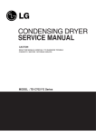
CONDENSING DRYER
SERVICE MANUAL
CAUTION
READ THIS MANUAL CAREFULLY TO DIAGNOSE TROUBLE
CORRECTLY BEFORE OFFERING SERVICE.
MODEL : RC9011** / RC8011** Series
JUL. 2008 PRINTED IN KOREA
P/No.: 3828EL9001K
IMPORTANT SAFETY NOTICE
The information in this service guide is intended for use by individuals possessing adequate backgrounds
of electrical, electronic, and mechanical experience. Any attempt to repair a major appliance may result in
personal injury and property damage. The manufacturer or seller cannot be responsible for the
interpretation of this information, nor can it assume any liability in connection with its use.
! WARNING !
To avoid personal injury, disconnect power before servicing this product. If electrical power is required
for diagnosis or test purposes, disconnect the power immediately after performing the necessary checks.
RECONNECT ALL GROUNDING DEVICES
If grounding wires, screws, straps, clips, nuts, or washers used to complete a path to ground are
removed for service, they must be returned to their original position and properly fastened.
IMPORTANT
Electrostatic Discharge (ESD)
Sensitive Electronics
ESD problems are present everywhere. ESD may damage or weaken the electronic
control assembly. The new control assembly may appear to work well after repair is
finished, but failure may occur at a later date due to ESD stress.
■ Use an anti-static wrist strap. Connect wrist strap to green ground connection point or unpainted
metal in the appliance.
- OR -
Touch your finger repeatedly to a green ground connection point or unpainted metal
in the appliance.
■ Before removing the part from its package, touch the anti-static bag to a green ground connection
point or unpainted metal in the appliance.
■ Avoid touching electronic parts or terminal contacts; handle electronic control assembly by edges only.
■ When repackaging failed electronic control assembly in anti-static bag, observe above instructions.
2
CONTENTS
1.SPECIFICATIONS ............................................................................................................... 4
2.FEATURES AND LOOK ...................................................................................................... 5
3.PART IDENTIFICATION ....................................................................................................... 6
4.PROGRAM CYCLE ............................................................................................................. 7
5.INSTALLATION INSTRUCTIONS ....................................................................................... 10
6.MAINTENANCE INSTRUCTIONS ...................................................................................... 12
7.COMPONENT TESTING TIPS ............................................................................................ 14
8.CONTROL LAY-OUT ........................................................................................................ 16
9.WIRING DIAGRAM ......................................................................................................... 17
10. TROUBLESHOOTING .................................................................................................... 18
11. DIAGOSTIC TEST ........................................................................................................... 21
12. DIASSEMBLE INSTRUCTIONS ........................................................................................ 28
13. EXPLODED VIEW .......................................................................................................... 33
3
1
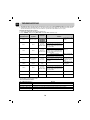
SPECIFICATIONS
ITEMS
MATERIAL & FINISHES
DRYING TYPE
WEIGHT
DIMENSION
STANDARD DRYING CAPACITY
CONTROL TYPE
POWER SUPPLY
MOTOR
HEATER
LED LAMP
DOOR SWITCH
THERMOSTAT
CONTROL TYPE
DRUM CAPACITY
SAFETY DEVICES
SENSING TYPE
FILTER
DRUM SPEED
DRUM
DRYER RACK
CHILD LOCK
TEMPERTURE CONTROL
BUZZER
ANTI-CREASE
FAVOURITE
MORE TIME
LESS TIME
TIME DELAY
DRUM INTERIOR LIGHT
LED DISPLAY
RC8011**
RC9011**
Condenstation
45 kg (Gross : 50 kg)
595(W) x 850(H) x 600(D)
8.0 kg
Electronic Control
AC 220~230V, 50Hz (16A)
210W
2500W
DC12V(30mA)
250V(5A)
240V(25A)
Electronic
125 Liter
Thermal Fuse (Motor)
Over current protect (Motor)
Thermostat
Micom electronic Control
1. Temperature : 2 thermistors
2. Humidity : Electrode Sensor
Removable
52~53 rpm
Stainless steel
Available
Available
Available
Available
Available
Available
Available
Available
Available
Available
Condenstation
45 kg (Gross : 50 kg)
595(W) x 850(H) x 600(D)
9.0 kg
Electronic Control
AC 220~230V, 50Hz (16A)
210W
2500W
DC12V(30mA)
250V(5A)
240V(25A)
Electronic
125 Liter
Thermal Fuse (Motor)
Over current protect (Motor)
Thermostat
Micom electronic Control
1. Temperature : 2 thermistors
2. Humidity : Electrode Sensor
Removable
52~53 rpm
Stainless steel
Available
Available
Available
Available
Available
Available
Available
Available
Available
Available
TIME DISPLAY
RUNNING STATUS INDICATOR
EMPTY WATER
CLEAN FILTER
TIME DISPLAY
RUNNING STATUS INDICATOR
EMPTY WATER
CLEAN FILTER
4
REMARK
LGEUK:13A, LGEAP:10A
LGEUK:2350W, LGEAP:1900W
Gentle button
Default : high
Dafault : OFF
Dafault : OFF
Maximum=100min.
Minimum=15min.
3~19 hours
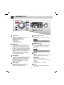
2
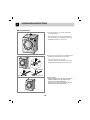
FEATURES AND LOOK
Ultra big Capacity Drum
LG Dryer has 9.0kg / 8.0kg capacity which is the ultra big capacity.
Energy
Lower Energy Consumption
Energy is saved by cutting-edge engineering design of drying system
and by optimized heating control. It’s a real money saving.
save
Reduced drying time
Drying time is shortened by efficient air flow mechanism and
optimized heater.
Innovative noise performance
Noise gets reduced by Noise-absorption & screening technology.
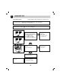
Easy of Use
Wide LED display using electric control.
Control Panel
RC9011A/B/C, RC8011A/B/C
LED Display
• Time Display
• Indicator Lamps & Left Time
Drying Level
• Iron
• Light
• Cupboard
• Very
• Extra
Program Selector
Additional Function
Buttons
• More Time
• Less Time
• Option
• Buzzer
• Time Delay/Favourite
Anti-Crease/Drum Light
5
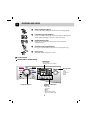
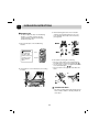
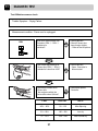
3
PART IDENTIFICATION
RC9011A1/B1/C1, RC8011A1/B1/C1
Water Container
Control Panel
Glass Door
Condenser Cover
Air Ventilation Grill
Accessory parts
1. Drain Hose Assembly
2. Dryer Rack Assembly
P/No. : 5001EL2001A
P/No. : 3751EL1002C
3. Stacking kit Assembly ( Purchased Seperately)
1
2
Holder : 2EA, Screw : 4EA Holder : 2EA, Screw : 4EA
Purchased Separately Purchased Separately
6
4
PROGRAM CYCLE
Time Delay
More Time/Less Time
You can use the Time Delay function to delay the
finishing time of drying cycle.
Maximum Time Delay is 19 hours.
Minimum Time Delay is 3 hours.
1. Turn the dryer on
2. Select cycle
3. Set time delay hour
4. Press Start/Pause button
Press More Time or Less Time until the desired
drying time is set.
Note
These buttons are available only with Timed
Drying, before you push Start/Pause button.
Child Lock (
Favourite
)
For the safety of your children, press More Time
and Less Time buttons at the same time for
about 3 seconds. You can see “
” sign on
LED window.
If there is some cycle you would like to make based
on your own drying habit, use “Favourite”.
Once favourite cycle is stored, you can repeatedly
use next time before changing the stored setting.
For instance, you turn power on and select Extra Dry
in Cotton Cycle and Low temp and Anti-Crease in
series and then lastly press “Favourite” until the
dryer beeps. It’s about 3 seconds. That’s all you have
to do.
The next time, when turning the dryer on and
pressing “Favourite” you can see the above options
you select displays on the panel.
Note
For “
” off, press More Time and Less Time
buttons at the same time for about 3 seconds.
Option
Gentle
- These are functioning to shorten or lengthen the
cycle time by increasing or decreasing
temperature.
Damp Dry Beep
- This is a function to inform time.
When is the most suitable for ironing with beeper
sound.
Crease Care
- This is a function to reduce wrinkles.
Anti-Crease
Anti-Crease is functioning to prevent creases and
rumples that are formed when the laundry is not
unloaded promptly at the end of drying cycle. In
this function, the dryer repeatedly runs and
pauses to the cycle end.
If the door is open during Anti-Crease process,
this function is cancelled.
Drum Light
During operating cycle, you can see the drum
inside by choosing drum light function.
It helps easy viewing the drying cycle.
Buzzer
This is a function to able to adjust volume of
beeper sound.
7
4
PROGRAM CYCLE
Cycle Selection Table
Standard
program
Electronic Auto Dry Cycles
Cotton (Whites and coloreds)
(Note) Select the gentle by pressing the option button for heat-sensitive items
Towels, dressing gowns
and bed linen
For thick and quilted fabrics
Extra Dry
Terry towels, tea towels, towels,
bed linen
For thick and quilted fabrics which do not need to be ironed
Very Dry
Bath towels, tea towels,
underwear, cotton socks
For fabrics which do not need to be ironed
Sheets, pillowcase, towels
For fabrics which do need to be ironed lightly, not completely
light Dry
Bed linen, table linen, towels, T-shirts
Polo shirts and work clothes
For fabrics which do need to be ironed
Iron Dry
Cupboard dry
Mixed-Fabric Cycles
(Note) Select the gentle by pressing the option button for heat-sensitive items
Bed linen, table linen, tracksuits,
anorak, blankets
For thick and quilted fabrics which do not need to be ironed
Shirts, blouses
For fabrics which do not need to be ironed
Trousers, dressers, skirts, blouses
For fabrics which do need to be ironed
Very Dry
Cupboard dry
Iron Dry
Quick Dry Cycles
A kind of linen and towel except
for the special fabrics
For the small loads of qualified fabrics with short drying times
Quick Dry
Timed Drying Cycles for selected length of time
Bath towels, bath robes, dishclothes,
Quilted fabrics made of acrylic
Small clothes & pre-dried laundry
Normal fabrics using hot temperature for 20minutes
Small clothes & pre-dried laundry
Normal fabrics using hot temperature 40minutes
Warm
Cool Air
All fabrics needing freshing, tumbles without heat
Special Fabrics
Wool
Silk, Women's thin clothes, lingerie
For wool fabrics
For fabrics which are heat-sensitive like synthetic fabrics
Soccer uniform, training wear
For 100% polyester material
For bulky items
Bed clothes
Wool
Delicate
Sports Wear
Bulkey Item
CAUTION
If the load is less than 1kg, please use "Timed Drying Course"
Your wool should be used in Wool program and heat-sensitive fabrics including silk, underwears,
lingerie should be used in delicates courses.
Otherwise, these clothes can cause undesirable drying results.
8
PROGRAM CYCLE
4
Course
Course
More time
Gentle
Detail
Less time
Extra
Very
X
X
X
O
X
X
X
O
O
Cotton
Cupboard
Light
Iron
Very
Mixed
Cupboard
Fabrics
Iron
Quick
Timed Cool Air
Drying
Warm
Delicate
Special Sports wear
Fabrics
Wool
Bulky Item
O
O
X
O
O
X
X
O
O
X
X
X
X
O
X
X
O
X
X
X
X
Time
Anti
Damp Dry Hand Crease
Buzzer
Favourite
Delay
crease Left Time
beep
Iron care
O
O
O
X
X
O
O
X
X
O
O
X
X
O
O
X
X
O
X
O
X
X
O
O
O
O
O
X
X
O
O
O
O
O
O
X
X
X
X
X
X
X
X
O
X
X
X
X
X
X
X
O
X
X
X
X
X
X
X
O
O
O
O
O
O
O
O
O
O
O
O
O
O
O
O
9
O
O
O
O
O
O
O
O
O
O
O
O
O
O
O
O
O
O
O
O
O
O
O
O
O
O
O
O
O
O
125
120
115
103
97
53
48
41
50
40
40
45
30
21
60
5
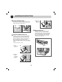
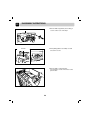
INSTALLATION INSTRUCTIONS
Level the Dryer
1. Leveling the dryer is to prevent undesirable
noise and vibration.
When placing your dryer in an solid and level
area where water is not dripping and freezing,
flammable materials are not stored.
2. If the dryer is not properly level, adjust the front
leveling legs up and down as necessary.
Turn them clockwise to raise and
counterclockwise to lower until the dryer is not
wobbling both front-to-back and side-to-side.
Adjustable Feet
Dryer is raised
Adjustable Feet
Dryer is lowered
Adjustable Feet
Diagonal Check
When pushing down the edges of the machine, the
machine should not move up and down at all.
(Please, check both of two directions)
If machine rocks when pushing the machine top
plate diagonally, adjust the feet again.
10
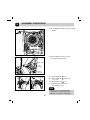
5
INSTALLATION INSTRUCTIONS
3. After detaching protection sheet of doubleside tape, align stacking kit holes rear cover
holes and then attach tape to the washer by
pressing hard.
Stacking Kit
In order to stack this dryer on LG Washing
machine, you must purchase the LG
stacking kit that is fitted by LG washing
machine top plate size.
1. Place the LG dryer on the LG Washing
machine.
WARNING
When Placing
the dryer, pull
power cord out of
a power source.
Don’t drop the
dryer.
Dryer
Washer
4. Assemble a stacking kit as following.
• Screw 2 screws which is unscrewed earlier to
assemble dryer rear back and stacking kit.( 1 )
• Use accessory screws to assemble washer rear
cover and stacking kit. ( 2 , 3 )
• The procedure for the opposite side will be the
same.
2. Unscrew Rear cover in the Base by unscrewing
2 screws.
Condensate Drain
The dryer can drain water without delivering to
water container. Water is directly pumped out
of the dryer.
11
6
MAINTENANCE INSTRUCTIONS
Front Ventilation Grille
3. Connect
drain hose
to the kit.
Vacuum the front ventilation grill 3~4 time a year to
make sure there must be no build-up of lints or dirts
which cause improper intake air flow.
Moisture Sensor?
Condensed Water Drain-out
Normally, condensed water is pumped up to water
container where water is collected until emptied.
Not only using water container, but water can be
drained out directly to drain hose especially when
dryer is stacked on top of washing machine.
With connecting kit for drain hose, you can simply
change water path and water reroute to the drainage
facility.
Please follow the below steps.
1. Take
connecting
kit out.
2. Separate
water
container
hose from
the kit.
12
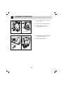
This device functions to sense the moisture
remaining contents of the laundry during
operation which means it must be cleaned all
the time. The main reason of cleaning this part
is to remove the build-up of lime scale on the
surface of sensor. Wipe the sensors inside
drum (Shown in the picture).
6
MAINTENANCE INSTRUCTIONS
CAUTION
• Power cord must be unplugged before this
work to avoid danger of electric shock.
• The bulb itself could be very hot when the
dryer just finishes its operation. So before
changing the bulb, be sure that the inside of
the drum is cool down.
5. Rotate the lamp cover in anti-clockwise
direction (from your side) till it stops to rotate
and pull it with certain amount of force, and
take out the LED Lamp Cover Assembly.
1. Disassemble Top Cover, Drawer and Control
Panel Assembly as explained in Page no. 30
2. Disconnect the Red Connector.
Legs for holding
Assembly
6. Now insert new LED Lamp Cover assembly
from inside and pull the connector and its
wire toward outside through the hole , at
same time rotate the lamp cover in clockwise
direction, till it stops to rotate.
3. Now take the wire of Lamp Cover Assembly
out of the hooks as shown in picture.
7. Screw the screw taken out during
disassembly.
8. Adjust the Wire through the hooks and
Connect the red connector.
4. Open the Door, Put your one hand inside
the Drum and unscrew the screw on Lamp
Cover with the help of a screw driver.
9. Assemble the control panel, Drawer and Top
plate.
(DO NOT forget to connect the connectors of
Control Panel Assembly in PCB Assembly).
13
7
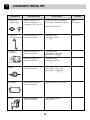
COMPONENT TESTING TIPS
Component
1. Thermostat
(Manual type)
Test procedure
Measure resistance of
Terminal to terminal
1) Open at 170°C (-10/+5°C)
Check result
Measure resistance by pressing
button When resistance becomes ∞
Remark
Safety
Thermostat
Resistance value < 5Ω
2. Thermistor
(Low temperature )
Measure resistance of
terminal to terminal
Resistance value :
10KΩ 5% (at 25°C)
3. Heater,
Thermistor
Measure resistance of
Terminal to terminal
Resistance value :
Yellow/White : 28.96 1Ω
Blue/White : 56.29 2Ω
Measure resistance of
therminal to terminal
Resistance value :
200KΩ 5% (at 25°C)
4. Motor
Measure resistance of
Terminal to terminal
Resistance value(20°…):
Blue / White : 15.3( 7%)Ω
Red / White : 18.5( 7%)Ω
5. Capacitor
Measure capacitance of
Terminal to terminal
Capacitance value : 10±0.2µF
6. Pump
Measure resistance of
Terminal to terminal
Resistance value(20°C):
210(±5%)Ω
Thermistor
14
Cover, Front
Heater
7
COMPONENT TESTING TIPS
Component
7. Door S/W
8. Lamp holder
Test procedure
Measure resistance of the
Following terminal
1) Door switch knob : open
1 Terminal : “COM”- “NC”
(1-3)
2 Terminal : “COM”- “NO”
(1-2)
2)Door switch push : Push
1 Terminal : “COM”- “NC”
(1-3)
2 Terminal : “COM”- “NO”
(1-2)
LED LAMP
Check result
1 Resistance value < 1Ω
2 Resistance value ÷
1 Resistance value ÷
2 Resistance value < 1Ω
DC 12V
15
Remark
The state that
knob is Pressed is
opposite to open
condition
8
CONTROL LAY-OUT
PWB ASSEMBLY DISPLAY LAY-OUT
OPTION PART
MODEL
P/NO
DP1
DP2
DP3
DP4
DP5
DP6
RC8011*
RC9011*
X
X
X
X
X
X
EBR50559201
RC8011**
RC9011**
X
X
O
X
X
X
EBR50559202
O : Option diode(DP) applied
X : Option diode(DP) not-applied
PWB ASSEMBLY LAY-OUT
16
9
WIRING DIAGRAM
17
10
TROUBLESHOOTING
1. This TEST should be used for Factory test/Service test. Do not use this DIAGNOSTICTEST other than specified.
2. Activating the Heater manually with Door open may trp the Thermostat attached to the Heater, therefore do not
activate it manually, (Do not press the door switch to operate the heater while the door is open)
Activating the diagnostic test mode
1. Unit must be in Standby (unit plugged in, display off)
2. Press “POWER” while pressing “More time” and “Less time” simultaneously.
Pressing the
“START/PAUSE”button
CHECKING
ACTION
None
Electric control
CHECKING
POINTS
DISPLAY
Check all leds for operation.
Motor
70~240
Measured
Moisture Value
Twice
Motor
70~240
Measured
Moisture Value
3 times
Motor + Heater 1
Current
temperature
4 times
Motor+Heater 1
+Heater 2
Current
temperature
5 times
Motor off + Heater off
Pump on
Water level in
sump
6 times
Motor
70~240
Measured
Moisture Value
7 times
Motor off
000
8 times
Control Off
Once
All the LED's on with
buzzer.
Motor run counterclockwise.
Displays Moisture Sensor Operation: If
moisture sensor is contacted with damp
cloth. The display number is below 180,
in normal condition.
Course LED's on.
Motor run clockwise.
Displays Moisture Sensor Operation: If
moisture sensor is contacted with damp
cloth. The display number is below 180,
in normal condition.
Motor run clockwise.
Heater run(Display the temperature of low
temperature themistor located under door.)
Only option Button
LED's on.
Motor run clockwise.
Heater run(Display the temperature of high
temperature thermistor located in heater
assembly.)
LED's of Time Delay,
Favorite, Anti-crease
and Buzzer options
glitter.
Pump run
All the LED's of SubJog dial (Drying
Level) glitter.
Motor run clockwise.
Displays Moisture Sensor Operation: If
moisture sensor is contacted with damp
cloth. The display number is below 180,
in normal condition.
LED's of Gentle and
Quick option glitter.
All the LED's on.
All the LED's on / Off.
Auto Off
Data Display
-Tested under normal operation mode.
- Press the button as follows.
No. of Button pressing
More time + Time Delay
More time + Favourite
Display
Moisture data
Temperature sensed by low temperature thermistor (located under door)
More time + Anti-Crease
Temperature sensed by High temperature thermistor (located in heater assembly)
More time + Drum Light
Remaining water data by water level sensor
18
TROUBLESHOOTING
10
Error Mode
•
: LED displays “
” in case of the door open. The door must be closed and
start Button must be pressed for re-operation. (See the 22 page)
: splay thermistor symptom.
•
Display
Symptom
tE 1
Low temperature thermistor open
tE 2
Low temperature thermistor short
tE 3
High temperature thermistor open
Check point
•
: Check the main PCB red 4 pin housing not inserting Blue harness in red 4 pin
( number 2 , 4 )
Low temperature thermistor connector not inserting
Main PCB Micom not soldering
•
: Check the main PCB red 4 pin housing Short of Blue harness in Red 4 pin.
Low temperature thermistor short : check the resitance( see 15 page )
Main PCB Micom short
•
replace Main PCB
: Check the white 8 pin housing (No. 3,4) in main PCB.
And Check the high temperature thermistor connector in rear cover part. ( blue wire )
19
10
TROUBLESHOOTING
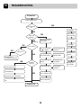
Power-On
Power button press
NO
Led-Segment
On
Plugged in
YES
Drum not
Roating
NO
(Rotating)
YES
NO
Power button
Lock:No buzzer
YES
Circuit breaker
trip
Start button Lock:
: No buzzer
Low voltage
Door Open?
Door is not closed
("
") display
See the Page 24
check list
Lamp on?
NO
Drum Belt broken
Replace Belt
Lamp Broken
Connector malfunction
Low temperature
Harness Wire
broken
Led broken
NO
Properly
Drying?
Check Heater Power
Check Filter sign
glitters
Clean filter and
Condenser
Empty water sign
Empty water
container
Thermostat trip
YES
Over clothes Load
Check thermistor open/short
Motor malfunction
Fan
Power-Off
20
Display pcb
wire broken
DIAGOSTIC TEST
11
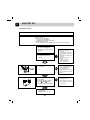
Test 1 : ELECTRIC SUPPLY & CONTROL CHECK
Trouble Symptom : No power to the dryer or the controller
Measurement condition : Power is on.
[ Caution] Electric shock. Please test after grounding check.
WH2
RLY1
Power voltage is within
standard range
(AC 215V~245V)?
• Check the
- Circuit breaker
• Check after pulling Black 2
pin and WH2 connector out
from controller.
• Check or replace the
controller
• Check the range of black pin
Black pin 4 ~WH2 pin 2 is
within AC 215~245V?
• Check connection of power
cord and harness assembly.
• Check WH2 pin 2 - Black
pin 4 of connector and secure
that range is between AC
215~245V?
• Check the harness
• Check or replace the
power cord
• Check the WH2 Pin 2
Check the short of harness
assembly and the connection.
In the case that the dryer is not working, when controller is
powered and display button is properly working, Check
RLY1 in the controller.
21
11
DIAGOSTIC TEST
Test 2 DOOR SWITCH / LAMP CHECK
Trouble Symptom : Malfunction of lamp operation and door switch
No operation of pump motor
Displays “
” in case of the door closed.
The door must be closed and start.
Measurement condition : Check if they are working while being connected to power supply.
When door is opened, lamp
turns on?
(Tumbling stops)
Check door switch
movement.
- See the left picture.
Check and replace lamp.
- See the 14,16 page
When door is closed, lamp
turns off?
• Door switch is working
normally.
When "Start" button is
pressed, the dryer is working?
When door is opened or
closed, door switch hook is
not broken?
• Replace door hook and
close the door.
• With door closed, check voltage of
connector RLY 1 and YL3 2
which are pulled out from
controller in advance. The voltage
range is between AC 215~245V?
• Door frame is distorted
• Check door switch
- See 16 page
Check or replace Controller Assembly
Replace Harness and connector
• With door closed, when
"Start" button is pressed,
lamp turns off and
controller is working, but
the dryer is not working.
22
11
DIAGOSTIC TEST
Test 3 Motor check
Trouble Symptom : Motor malfunction, Occurrence of the “Clean filter” repeatedly
Measurement condition :
• Power cord is unpluged.
• Door is closed.
• Check the user condition.
- Put over load into drum?
- Normally Input Voltage and Hertz?
• Pre-Check door switch
(If door switch has contact problem, pump motor is not working.)
• Before check process, Check
the motor rotating by the
Diagnostic test mode "See the
19 page”.
• When power is on and press
the start button, motor is
rotating.
RLY1
BL2
• Check the harness connection.
- Motor part : Blue 2 pin
housing.
- Controller part : Blue 2 pin
housing ( Orange and Blue
wire ).
- Capacitor part : White 2 pin
housing.
• Check the belt ( position /
broken ).
• Check the Controller
- TR1 , TR2 Broken ?
• Check the slide ( 3 ea ).
• During operation, motor noise
is occurred ?
• Check Capacitor volume.
- See component test page.
- See the left picture.
• Check belt is burst.
• Check structural restriction.
( Motor supporter / Air guide
Blower )
With RLY1, BL2 being unplugged
from Controller,
1) RLY1 1 - BL2 1 resistance
2) RLY1 1 - BL2 2 resistance
measurement ranges 18Ω~26Ω ?
• Check or replace Motor
- Check Motor TP
• Check controller
-See page 17
(PCB Assembly Lay-out)
23
• Check Harness connection
• Check the Motor resistance.
(see page 15 )
11
DIAGOSTIC TEST
Test 4 Heater check
Trouble Symptom : Motor malfunction, ventilation error
Trouble Symptom : Heater is not working. Drying failure. The designated
temperature is not reached.
Measurement condition : 1 Power cord is unplugged.
RLY2
WH2
RLY1
RLY1
With Tab relay housing
disconnected from Controller,
1) RLY1 2 - RLY2 1 resistance
ranges 26Ω~32Ω ?
2) RLY1 2 - WH2 pin 1
resistance ranges 53Ω~59Ω ?
• Check and replace
controller.
• RLY2 ~ WH2
• See page 17, PCB
assembly lay-out.
When check thermostat to
Heater,
• Replace Heater
it is less than 1Ω?
Manually get Thermostat
back (Press button )
Heater On/Off occurs
frequently
1. Clean Condensing unit :
2. Check if Lint filter is
damaged or clogged
24
• Check Harness
connection
11
DIAGOSTIC TEST
Test 5 Pump check
Trouble Symptom : Check if pump is out of order. " Empty water" signals.
Measurement condition : Power cord is unplugged.
Check the hose blocked with foreign body or twist.
(Measure with power on)
On QC test mode, when Pump
is on,
Electric noise doesn’t occur
while pumping?
• Disassemble Pump
- Check foreign objects
- Check impeller
restriction
- Check connection
hose clogged
(Measure after power is off.)
With YL3 disconnected from
Controller,
YL3 1 - YL3 2 resistance
ranges 205±10Ω ?
• Check or replace pump
• Check Harness
connection
• Check Pump sensor
• Check and replace Controller
- TR3
25
11
DIAGOSTIC TEST
Test 6 Thermister check
Trouble Symptom : Poor drying performance(over-drying or no drying). Abnormal
thermistor operation.
Measurement condition : Power cord is unplugged.
RD4
WH6
• Check and replace
Controller.
1) Check disconnected
Housing or severed
Wire.
2) Check the resistance
of thermistor.
3) Replace controller
and then recheck,
if anything else
occurs.
With RED 4 , WHITE 6 disconnected from
Controller, check
1) High temperature thermistor ( Wire color :
Blue ) White 6 pin 3 - White 6 pin 4
resistance ranges table data according to
surrounding temperature.
2) Low temperature thermistor ( Wire color :
Blue ) Red 4 pin 2 - Red 4 pin 4
resistance ranges table data according
to surrounding temperature.
• When measuring resitance of
Heater thermistor.
It range table data.
• Replace the thermistor
of heater.
• When measuring resitance of
Low temperature thermistor.
It range table data.
• Replace the low
temperature thermistor.
• Check Harness
Dryer
Temperature
Resistance
TH-Heater
10°C
Resistance
TH-Drum
Dryer
Temperature
TH1
TH2
19~111kΩ
40~50°C
113~75kΩ
5~4kΩ
50~60°C
75~50kΩ
4~2.5kΩ
20~30°C
250~180kΩ
11~8kΩ
30~40°C
180~113kΩ
8~5kΩ
60°C
26
50kΩ
2.5kΩ
Remark
11
DIAGOSTIC TEST
Test 6 Moisture sensor check
Trouble Symptom : Drying Failure
Measurement condition : Power cord is unplugged.
With RD4 disconnected from
Controller, RD4 ① - RD4 ③
resistance is
unlimited?
RD4
4
2
NO
• Check Harness
• Check if Sensor tips
have foreign objects
- Refer to the left picture
3
1
YES
Metal Wire
With metal tape attached to
Sensor tips, RD4 ① - RD4 ③
resistance is less than 10Ω?
NO
• Check Harness
- Open, Connector is
disconnected
YES
• Check and replace
Controller
After damp clothes touch
Sensor tips,
the range are within the
below table when QA-test?
NO
❄ IMC
DISPLAY
NOTE
40% ~ 60%
50 ~ 130
After Spinning
5% ~ 20%
100 ~ 200
Iron dry
-3 ~ +5 %
205 ~ 240
After normal dry
❄ IMC : Initial Moisture Contents.
27
12
DIASSEMBLY INSTRUCTIONS
1. Disassemble top plate by unscrewing 2
screws on the rear of the dryer.
TOP PLATE
2. After pulling drawer assembly out and
unscrew 2 screws.
DRAWER
3. Disassemble control panel by
unscrewing 2 screws on the Rear of the
panel frame.
28
DIASSEMBLY INSTRUCTIONS
1st Pull
4. Disassemble the lower cover by pulling
to the front.
2nd
Pull
12
DRAWER
5. Disassemble cabinet by unscrewing 2 at
the top and 3 at the rear (Left and right
are the same).
CABINET
6. Disassemble panel frame by unscrewing
4 at the front.
PANEL FRAME
29
12
DIASSEMBLY INSTRUCTIONS
7-1. Disassemle the door by releasing the
2 screws.
7-2. Disassemble the door switch.
Pu
ll
7-3. Disassemble the cabinet cover by
releasing the 10 screws.
7-4. Disassemble the Door Switch.
DOOR
7-5. Disassemble the cover, cabinet.
DOOR SWITCH
8-1. Disassemble the spring holder.
8-2. Releasing the belt on the pulley.
2
1 Pull
9-1. Disassemble the main PWB cover as
pulling the hook.
PUSH
9-2. Pull out the harness from the housing.
LL
PUSH
PU
CABINET COVER
30
DIASSEMBLY INSTRUCTIONS
12
10. Disassembling the side frame by releasing
4 screws
11. Disassemble the housing of motor,
heater, pump and capacitor.
CAPACITOR
PUMP
HOUSING
MOTOR
HOUSING
12-1. Disassemble the 1 hose.
DISPENSER
12-2. Disassemble the 2 Holder from
cover, rear.
3
12-3. Disassemble the 3 hose.
2
12-4. Releasing the dispenser by
unscrewing 1 screw.
Note
If the hose is assembled unsuitable
“empty water” error message will be
indicated on the LED or LCD display.
31
12
DIASSEMBLY INSTRUCTIONS
13-1. Disassemble the duct by releasing
the 7 screws.
13-2. Release the durum nut using tool.
13-3. Disassemble the air guide by
releasing the 1 screw.
DUCT
AIR GUIDE
14-1. Disassemble the COVER REAR by
releasing the 2 screws.
14-2. Disassemble the drum.
COVER
REAR
32
13
EXPLODED VIEW
Control Panel & Top plate Assembly
A100
A110
A113
A111
A160
A112
A120
A150
A130
A140
33
13
EXPLODED VIEW
Cabinet Cover & Door Assembly
Transparent door
B103
B100
B107
B106
B102
B101
B124
B127
B121
B140
B130
B150
B125
B120
34
B122
13
EXPLODED VIEW
Base & Motor Assembly
C310
C320
C330
C290
C250
C130
C165
C160
C142
C300
C140
C150
C110
C120
C100
C230
C240
C210
C230
C200
C180
35
13
EXPLODED VIEW
Back Cover & Drum Assembly
D122
D120
D100
D110
D121
D150
D180
D156
D210
D170
D200
D130
D152
D157
D151
D140
36