1
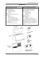
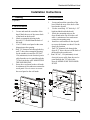
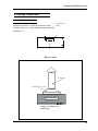
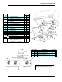
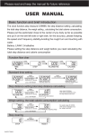
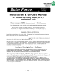
User’s Manual Metro/ Legacy Residential Wall Mount Hood ® Models: 3400 Legacy 30” Hood 500 cfm 3405 Metro 30” Hood 500 cfm 3410 Legacy 36” Hood 900 cfm 3415 Metro 36” Hood 900 cfm C L IS T E D ® L IS T E D 3420 Legacy 42” Hood 900 cfm 3425 Metro 42” Hood 900 cfm ® Residential Use Only READ AND SAVE THESE INSTUCTIONS INSTALLER: LEAVE THIS MANUAL TO HOMEOWNER HOMEOWNER: USE AND CARE INFORMATION ON PAGE 15 © 2001 HEARTLAND APPLIANCES INC. #3936 052301 Table of Contents Important Safety Instructions.................. 2 Parts List ............................................... 3 Technical Specifications .......................... 4 Installation Instructions .......................... 5 1. Framing ......................................... 5 A. Back Installation ................. 5 B. Strip Installation ............... 5 C. Top Installation ................... 6 2. Preparating the Installation .............. 7 3. Hood Installation ............................ 8 A. Back Installation ................. 8 B. Strip Installation ............... 9 C. Top Installation ................. 10 4. Ducting Connection ....................... 11 A. Cut Out Hole Information ... 11 B. Ducting Installation.............. 12 C. Method of Ducting ............ 12 5. Duct Cover Installation ................... 12 6. Backsplash Installation ................... 12 7. Electrical Connections .................... 13 8. Heat Lamp ..................................... 13 9. Filter Installation ............................. 14 Maintenance Instructions ........................ 15 1. Blower and Filters .......................... 15 2. Stainless Steel or Enamel Finish ..... 16 Operation Instructions .............................. 16 Wiring Diagram ........................................ 18 Service Parts Diagram ............................. 19 Warranty ............................................... 20 Residential Wall Mount Hood Important Safety Instructions WARNING WARNING TO REDUCE THE RISK OF FIRE, ELECTRIC SHOCK OR INJURY TO PEOPLE OBSERVE THE FOLLOWING: TO REDUCE THE RISK OF INJURY TO PEOPLE IN THE EVENT OF A RANGE TOP GREASE FIRE, OBSERVE THE FOLLOWING*: 1. Use this unit only in the manner intended by the manufacturer. If you have questions, contact the manufacturer at the address or telephone number listed in the warranty. 1. SMOTHER FLAMES with a close-fitting lid, cookie sheet or metal tray, then turn off the burner. BE CAREFUL TO PREVENT BURNS. IF THE FLAMES DO NOT GO OUT IMMEDIATELY, EVACUATE AND CALL THE FIRE DEPARTMENT. 2. Before servicing or cleaning unit, switch power off at service panel and lock service disconnecting means to prevent power from being switched on accidentally. When the service disconnecting means cannot be locked, securely fasten a prominent warning device, such as a tag, to the service panel. 2. NEVER PICK UP A FLAMING PAN - you may be burned. 3. DO NOT USE WATER, including wet dishclothes or towels. This could cause a violent steam explosion. 4. Use an extinguisher ONLY if: 3. Installation work and electrical wiring must be done by qualified personnel in accordance with all applicable codes and standards, including fire-rated construction codes and standards. 4. Sufficient air is needed for proper combustion and exhausting of gasses through the flue (chimney) of fuel burning equipment to prevent backdrafting. Follow the heating equipment manufacturer’s guidelines and safety standards such as those published by the National Fire Protection Association (NFPA), and the American Society for Heating, Refrigeration and Air Conditioning Engineers (ASHRAE), and the local code authorities. 5. When cutting or drilling into wall or ceiling , do not damage electrical wiring and other hidden utilities. 6. Ducted fans must always be vented to the outdoors. 7. Do not use this unit with any solid-state speed control device. 8. To reduce the risk of fire, use only steel ductwork. A. You own a Class ABC extinguisher and you know how to operate it. B . The Fire is small and contained in the area where it started. C . The fire department has been called D. You can fight the fire with your back to an exit. (* Based on “Kitchen Fire Safety Tips” published by NFPA) CAUTION 1. For general ventilating use only. Do not use to exhaust hazardous or explosive materials and vapors. 2. To avoid motor bearing damage and noisy and/or unbalanced impellers, keep drywall spray, construction dust, etc. off power unit. 3. Your hood motor has a thermal overload which will automatically shut off the motor if it becomes overheated. The motor will restart when it cools down. If the motor continues to shut off and restart, have the hood serviced. 4. For best capture of cooking impurities the bottom of the hood should be at a minimum of 20” (24” over a gas range) and at a mazimum of 36” above the cooking surface. 9. This unit must be grounded. 5. Two installers are recommended to install this hood, because of its large size and weight. TO REDUCE THE RISK OF A RANGE TOP GREASE FIRE: 6. Please read specification label on product for further information and requirements. 1. Never leave units unattended at high settings. Boil overs cause smoking and greasy spil overs that many ignite. Heat oils slowly on low or medium settings. 7. To reduce the risk of fire and to properly exhaust air, be sure to duct air outside-Do not exhaust air into spaces within walls or ceilings or into attics, crawl spaces or garage. 2. Always turn hood ON when cooking at high heat or when cooking flamming foods. 8. This product is equipped with a thermostat which may start blower automatically. To reduce the risk of injury and to prevent power from being switched on accidentally, switch power off at service panel and lock or tag service panel. 3.Clean ventilating fans frequently. Grease should not be allowed to accumulate on the fan or filter. 4. Use proper pan size. Always use cookware appropriate for the size of the surface element 9. Because of the high exhausting capacity of this hood, you should make sure enough air is entering the house to replace exhaused air by opening a window close to or in the kitchen. 3 Residential Wall Mount Hood Parts List Parts included with your unit: Parts to be purchased separarately: Canopy hood assembly Blower asssemblies-installed Adaptor with dampers Transition User’s Manual Filters (2,3, or 4 depending on hood size) Installation kit Wood strip Wire clamp connector 3/8” screws for lower installation 3/4” screws for hood installation (may not need all screws, depending on hood size and blower quanitity) Halogen lights (2) Size R20, 50 Watts maximum Backsplash (optional-from Heartland) Duct cover (optional-from Heartland) Heat lamp bulbs (2) Size IR175R PAR 175 Watts maximum Red Infared Duct tape (2” wide) Wall anchors (if needed) Standard ducting: 8” Rigid Galvanized ducting Flashings & Rain Caps: 8” dia (for square rain caps, use an equivalent cross sectional area). Flashings & rain caps are available from local Building Supply Centers or can be custom made by local sheet metal shops to match home’s features Duct Cover Kit (Optional) Transition Adaptor Vent Hood SplashBack Kit (Optional) 4 Residential Wall Mount Hood Technical Specifications 12" D u ct co ver (op tion al) 12" 8" A sk for kit n u m b ers: 3 8 0 4 fo r 3 0 " 3 8 0 5 fo r 3 6 " 3 8 0 6 fo r 4 2 " an d sp ecify colo ur 11-1 /2 " Tra ns itio n 9 7 /8" x 4 1/4 " to 8" (251 m m x 108 m m to 2 03 m m ) Tra ns itio n A d ap tor w ith d a m pe r 18" P ow er s u p ply B lo w e r F ilte rs Heat lam ps P iv o ta b le h a lo ge ne lig h ts 24" U p p er s e c tio n B ac ks p la s h (op tion al) inc lud ing w a rm ing s h e lf, u p p er a n d low er S ec tio n s 3 0 " to 3 6 " A sk for kit n u m b ers: 3 8 0 1 fo r 3 0 " 3 8 0 2 fo r 3 6 " 3 8 0 3 fo r 4 2 " an d sp ecify colo u r L o w er s e c tio n Hood Model 30” Power supply 120 Vac, 60 Hz Lighting power R20 Halogen bulbs (2) 2X50W Heating lamp power R38 Infrared (2) 2 X175 W (not supplied) Blower quantity 1-500 CFM Hood Width 30" Blower power 165 W Maximum unit power 615 W 36” 42” same same same same same same 1-900 dual 36" 330 W 780 W 1-900 dual 42” 330 W 780 W 5 Residential Wall Mount Hood Installation Instructions 1. Framing B. Strip Installation (3 options) 1. A. Back Installation 2. 1. 2. 3. 4. 5. Locate and mark the centerline of the hood. Mark the area of the center back of the hood on the drywall. Mark a rectangular opening in the drywall, 1/2" smaller than the back of the hood. Cut 1/2" thick wood panel at the same dimensions as the opening. Drill 7/8" diameter hole through the dry wall 2” above the rectangular opening, for the conduit wire and run 120 VAC, 15A (minimum) circuit electrical power cable from the service panel through the 7/8" hole in the dry wall. MAKE SURE THE POWER IS OFF. Screw the wood panel to the wall studs. A minimum of two studs must contact the wood panel. Use six screws to secure the wood panel to the wall studs. 3. 4. 5. 6. Locate and mark the centerline of the hood. Mark the area of the back of the hood on the drywall. Use the wood strip 1/2" thick by 1-1/2” high (included inside the hood). Screw the mounting strips to the drywall and make sure to hit the wall studs. A minimum of two studs must contact the mounting strip. Install two wall anchors to the drywall to secure the bottom rear hood. See the sketch for location. Drill 7/8" diameter hole through the drywall 2” above the area of the back of the hood for the conduit wire. Run 120 VAC, 15A (minimum) circuit electrical power cable from the service panel through the 7/8" hole in the drywall. MAKE SURE THE POWER IS OFF. 6 Residential Wall Mount Hood C. Top Installation 1. 2. 3. 4. 5. Locate and mark the centerline of the hood. Use wood panel of 1/2" thick by 12" high (see the sketch to determine width of panel). Screw two 2" X 4" (thin side down) perpendicular and at the bottom of the wood panel. See sketch for location. Screw a second set of 2" X 4’s angled to reach the front end of both previous 2" X 4"s and each top side of the wood panel. Screw another 2" X 4" inside the ends of first set of 2" X 4"s (wide side down). 6. Add one 2" X 4" (thin side down) in the middle when using a to blower unit. Add two 2" X 4’s (thin side down) in the middle when using a three blower unit. With one blower unit, no middle stud is necessary 7. Drill 7/8" diameter hole through the 1/2” tick wood panel and drywall 2” above the top of the hood for the conduit wire. 8. Run 120 VAC, 15A (minimum) circuit electrical power cable from the service panel through the 7/8" hole of drywall. MAKE SURE THE POWER IS OFF. CL 1 O p tio na l w oo d fram e s up po rt u se d w he n th e u nit in clud e s tw o b lo w e rs W o od p an e l o f 1 /2 " th ick Drill 7/8” hole in the drywall for the power supply. 4 Top o f th e h oo d 2 4 3 1 2" 6 5 3 /4 " 3 11" 3 /4 " 1 2" 1 5-1/2" 7 Residential Wall Mount Hood 2. PREPARE THE INSTALLATION Remove the installation kit from inside the hood. Make sure the following items are included: -Filters -Halogen lights (120V, 50W, PAR 20) -Wood mounting strip -Bag of parts including: (1) Wire clamp, (2) Wire connectors, (2) Wall anchors, (4) #10-2” countersunk head screws, (6) #8-3/4 screws, (10) #8-3/8” screws, (4) Locknuts, (2) Washers 3/16” ID x ¾” OK Using a Phillips #2 or a Robertson #2 screwdriver, unscrew the hood from the bottom of crate. Refer to figure below to locate all screws (fig A). discard the screws and remove hood from wood pallet. (fig A) 4 5 1 2 3 Parts sold separately: -Heat lamps (120V, IR 175W, PAR 38) -Backsplash (optional) -Duct (optional) Install the adaptor: A) Slide the adapter tab in its notch, onexterior side of the rought-in plate. B) Using two (2) #8-3/8” screws, secure the adapter to the top of the hood. C) Seal the adapter to the hood using duct tape. 8 Residential Wall Mount Hood 3. Hood Installation (3 choices depending on framing choice) A. Back Installation Note: Use only keyholes and holes shown in black, as illustrated below, and on the sketches provided. wire clamp connector 3 Keyholes provided for easy installation. These should all be used. Optional holes provided only for stronger installation when necessary. 1. 2. 3. 4. 5. 6. 7. 4 Mark the location of the 5 installation screws (keyholes) on the wood panel. Do not tighten the installation screws (3/4") down. The hood can be placed on them before tightening. Insert the electrical wire (power supply) in the hole, ensuring the wire clamp connector is in place. Insert the screw heads inside the keyholes of the hood. Move down the hood and insert the screws into the slot of the keyholes. Tighten the five screws to attach the hood firmly on the wood panel. Install (only if necessary) 2 or 4 additional screws at the locations shown on the sketch. The numbers of additional screws depend on the size of the hood. 6 3 /4 " 1 -1 /4 " 3 /4 " 1 -1 /4 " 1 3 -5 /8 " 30" FRO NT VIEW 1 -1 /4 " 1 -1 /4 " all other m odels 1 3 -5 /8 " FRO NT VIEW 9 Residential Wall Mount Hood B. Strip Installation Note: Use only keyholes and holes shown in black, as illustrated below, and on the sketches provided. w o o d m o u n tin g s trip Keyholes provided for easy installation. These should all be used. Optional holes provided only for stronger installation when necessary. 1. 2. 3. 4. 5. 6. 7. Install the two screws (3/4") in the wall anchors. Do not tighten the installation screws down so the hood can be placed on them before tightening. Insert the electrical wire (power supply) in the hole, ensuring the wire clamp connector is in place. Insert the screw heads inside the keyholes of the hood. Hold the hood with a slight angle to allow clearance space from the mounting strip. Move down the hood and insert the screws into the slot of the keyholes. Pivot the hood to insert the woodmounting strip inside the back cavity of the hood. Continue to hold the hood during this operation. Tighten the screws (4 or 6 depending on hood size) so the hood is firmly attached to the wood mounting strip. Firmly tighten the two screws on lower part of the hood to secure the hood on the wall. 1-5/8" 1 w a ll a n c h o r 2 wire clamp connector b ac k c a v ity 5 3 w ire c la m p 6 7 4 1" 1" # 3400 / # 3410 / # 3420 1-1/4" 13-5/8" 1-1/4" FR O NT VIEW 10 Residential Wall Mount Hood C. Top Installation Note: Use only keyholes and holes shown in black, as illustrated below, and on the sketches provided. 1 b o tto m v ie w Keyholes provided for easy installation. These should all be used. 3 Optional holes provided only for stronger installation when necessary. 1. 2. 3. 4. 5. 6. 7. 8. 2 Mark location of the 4-installation screws (keyholes) on the top wood frame. Do not tighten the installation screws (3/4") down. The hood can be placed on them before tightening. Insert the electrical wire (power supply) in the drywall hole. Insert the electrical wire in the hole of the hood, ensuring the wire clamp connector is in place. Insert the screw heads inside the keyholes of the hood. Push the hood to the wall and insert the screws into the slot of the keyholes. Tighten the four screws so the hood is firmly attached to the top wood frame. Install additional screws at the location shown on the sketch depending on number of optional 2" X 4"s previously installed. wire clamp connector 6 7 6-3/4 " 10-5/8" 3 0" 1-1/4 " TO P V IE W 1-1/4 " 8 b o tto m v ie w 1-5/8 " 10-5/8" 3 6" - 4 2 " 1-1/4 " TO P V IE W 1-1/4 " 11 Residential Wall Mount Hood 4. Ducting Connection A. Cut Out Hole Information 10 1/2”X4 1/2” cutout Cabinet cut out area: use the area shown in bold. Ceiling cut out area: use the diameter dimension of the transition. ( 8”) ¾" 30" 36" 42" CL Blower Vented 8 ” d ia d u c t Tra n s itio n to 8 ” d ia 30 to 42 Single or double blower unit ducting. 12 Residential Wall Mount Hood B. Ducting Installation C. Method of ducting 1. Select the most appropriate method for your installation 2. 3. 4. 5. Mark the opening area to cut out, as per dimensions and locations on sketches. Use standard 8”rigid galvanized ducting (available from local Building Supply Stores) Maximum run of ducting for 500 CFM is 40 linear feet and for 900 CFM is 45 linear feet. Each 90 degree elbow will reduce overall duct run by 10 linear feet and each 45 degree elbow will reduce overall duct run by 5 linear feet. Position the transition around the adapter. Use duct tape to seal the joint between the transition and the adapter. Respect the transition size for the 8”ducting throughout the installation. Standard flashings and rain caps are available from local Building Supply Stores or can be custom made locally to match the home’s features (there are no minimum height requirements that a rain cap must extend past the roof line) NOTE 1. To reduce the risk of fire and improper exhaust air, be sure to duct air directly outside. Do not vent exhaust air into spaces within walls or ceilings or into attic, crawls spaces or garages. 2. Make sure you tape all joints with duct tape. 3. Flexible ducting is not recommended 4. Rain caps should be oversized whenever possible to offset air flow reductions due to bug screens, etc. 5. If installing square rain caps, please ensure cross sectional area remains the same. D u ct O u tsid e w a ll Ta pe D u ct 2 nd flo or C e iling Ta pe D u ct O u tsid e W a ll 5. Duct Cover Installation 6. Backsplash Installation See separate installation instructions for this unit. See separate installation instruction for this A sk for kit nu m b ers: 38 04 fo r 30 " 38 05 fo r 36 " 38 06 fo r 42 " an d sp ecify co lo ur A sk for kit nu m b ers: 38 01 fo r 30 " 38 02 fo r 36 " 38 03 fo r 42 " an d sp ecify co lo ur 13 Residential Wall Mount Hood 7. Electrical Connections WARNING Risk of electrical shock. Electrical wiring must be done by qualified personnel in accordance with all applicable codes and standards. Before connecting wires, switch power off at service panel and lock service disconnecting means to prevent power to be switched on accidentally. Run power cable to installation location. Remove wiring cover, install wire clamp, insert cable in hood through wire clamp and secure by tightening the wire clamp. Connect cable into wiring box, located on rough-in plate, using wire nuts. Connect wires as follows: BLACK to BLACK, WHITE to WHITE and GROUND wire under ground screw. Reinstall wiring cover Ground Screw 8. Heat Lamps The heat lamps required are 120V, 175W max, infrared bulbs. (120V,1R 175W, PAR 38) You can use white halogen lights if warming shelves are not used. (120V, 90W, PAR 38) Install the lamps by rotating them clockswise into their socket holder. Heat lamps are not included with Hood and not available from Heartland Appliances. 14 Residential Wall Mount Hood 8. INSTALL FILTERS Caution: remove protective plastic film covering filters installing them. It is recommended to install side filters first and finish with center one. MESH FILTER INSTALLATION 4 1 3 2 1.Insert upper end of filter into the hood (finger sized cup side). 2.Raise lower end toward the inside of hood. 3.Position lower end of filter into channel. 4.Using finger sized cup, pull on the upper end of filter and insert it under the inner retaining piece. Finger sized cupcup in filter Finger sized in filter 15 Residential Wall Mount Hood 9. USE AND CARE GREASE FILTERS AND IMPELLER(S): The grease filters, impeller(s) and grease collector channel should be cleaned frequently. Use a warm detergent solution. Grease filters and impeller(s) are dishwasher safe. To remove mesh filters, using finger sized cup, pull on the upper end of filter and disengage it from under the inner retaining piece. Then, pull out filters from hood. Use following instructions to clean the blower. (Impellers are dishwasher safe) Remove cover from the blower assembly. Remove the impeller(s) by pulling it (them) out gently. (see pictures below) CAUTION For dual blower unit, make sure the impellers are correctly installed; the hood will not work properly if the impellers are reversed. In the dual blower, both impellers are different: one rotates clockwise and the other one rotates counter clockwise. Each wheel and motor have an arrow and a number on them, you must match them correctly (see drawing below). 16 Residential Wall Mount Hood Hood Cleaning: Stainless Steel: How to maintain its “BRIGHT LOOK” Do: -Wash surfaces regularly with a clean cloth or rag soaked in warm water with mild soap or dishwashing detergent. -Always clean in the direction of original polish lines. -Always rinse well with clear water (2 or 3 times) after cleaning. Wipe dry completely. -You may also use a specialized household stainless steel cleaner. Don’t: -Do not use any steel or stainless steel wool or any other scrapers to remove stubborn dirt. -Do not use any harsh or abrasive cleansers. -Do not allow dirt to accumulate. -Do not let plaster dust or any other construction residues reach the hood. During construction or renovation, cover the hood to make sure no dust sticks to stainless steel surface. Avoid: (when choosing a detergent) -Any cleaners that contain bleach will attack the stainless steel. -Any products containing: chloride, fluoride, iodine or bromide will deteriorate surfaces rapidly. -Any combustible products used for cleaning such as acetone, alcohol, ether, benzol, etc., are highly explosive and should never be used close to a range. Enamel finish: Clean with warm water and mild detergent only. If discoloration occurs, use a good enamel polish such as automotive polish. (DO NOT use a rough abrasive cleaner or porcelain cleaner). 10. OPERATION Always turn ON your hood before you begin cooking in order to establish an air flow in the kitchen. Let the blower run for a few minutes to clear the air after you turn off the range. This will help keep the whole kitchen cleaner and brighter Electronic Control 1) Delay Switch 2) Start, stop, speed selectiuon switches 3) Master off / Filter maintanence switch / Heat Detector 4) Light switch 17 Residential Wall Mount Hood 1. Delay Switch: When a fan speed is selected, press the delay switch to activate its function. The corresponding speed indicator light will start flashing to indicate this function is activated. The fan will continue to operate for 5 minutes and will stop automatically. To cancel the delay function, press the delay switch once again. 2. Start/Stop Speed Selection Switches: Press the switch corresponding to the desired fan speed. The light indicates the selected speed, speed “1” being the SilentsureTM* mode. To turn off the fan, press once more on the corresponding fan speed switch. 3. Master Off/Filter Maintenance Switch/Heat Detector: (this switch has a triple function) a) To turn OFF the motor(s) and the lights simultaneously, press the switch once. b) After 25 hours of operation, the filter maintenance light indicator will turn itself ON. This indicates that the filters and the blower wheel(s) need to be cleaned in order to maintain efficient operation of the unit. The indicator light will stay ON until the function is reactivated by pressing this switch. c) The light indicator is used for the SmartventTM* function as well (see below). Smartvent TM*: When an excessively high temperature is detected, the detector takes control over the blower and ensures that an appropriate ventilation is produced. The controller is equipped with two detection levels. Protected Mode Level 1: When medium heat is detected, the blower sets itself to speed 2, the corresponding light indicator comes ON and the F indicator flashes. Protected Mode Level 2: When a greater heat is detected, the blower then sets itself to speed 3, the light indicator 3 turns ON and the F indicator flashes. WARNING The protected mode can start the blower even if the hood is turned OFF. In protected mode, it is impossible to turn the blower OFF with the push buttons. If you must stop the blower, do it from the main electrical panel. The blower will remain ON until the heat is back to normal and then returns to the speed previously selected. 4. Light Switch: The light switch allows three different lighting levels according to your needs (2 or 3 x 50 Watts maximum). Use halogen light bulbs (120V, 50W, PAR 20). 5. Heat Lamp Switches: Press the black rocker switches on the halogen light panel to activate the heat lamps independently. Use infrared light bulbs (120V, IR175W, PAR 38) or white halogen bulbs (120V, 90W, PAR 38) if food warming shelves are not used. WARNING Never place highly flammable material under heat lamps. *TM in Canada only, US TM pending. 18 Residential Wall Mount Hood 10. WIRING DIAGRAM 19 Residential Wall Mount Hood KEY # 1 2 3 5 6 7 8 9 10 11 12 13 14 15 16 17 18 19 20 PART # 02563 02414 03882 13216 13217 13218 03686 03597 03580 02543 02577 02772 02773 * * * * 02802 * * 3394 33955 3395 33956 * 03888 DESCRIPTION BLACK SPST ROCKER SWITCH AUTOTRANSFORMER PORCELAIN SOCKET LIGHT GREASE COLLECTOR 30" SS GREASE COLLECTOR 36" SS GREASE COLLECTOR 42" SS FILTER CLIP ELECTRONIC CONTROL H098 NYLON SPACER #6-32 x 1/2" CANOPY PUSH BUTTON HEYCO PLUG #1300 FEMALE MOTOR CONNECTOR MALE MOTOR CONNECTOR SCREW #8-3/8" SCREW #6 x 1/2" PAN HEAD LOCK NUT #8-32 SCREW #8-32 x 1/2" QDRX NYLON SPACER MF 1/4" x 9/16" MACHINE SCREW #6-32 x 1/4" LOCK NUT #6-32 FILTER 11.925" x 8.95" FILTER 11.925" x 11.950" CAPSYLITE LAMP PAR 20 PARTS BAG: 8 - screws #8x3/4", 1 - wire clamp, 4 - screws #10x2", 2 - wall anchors, 2 - washers, 4 - nuts #10-32, 8 screws #8x3/8", 2 - wire connectors QTY/WIDTH 30" 36" 42" 2 2 2 2 2 2 4 4 4 1 1 1 3 3 4 1 1 1 3 3 3 6 6 6 4 4 4 1 1 1 1 1 1 7 7 7 3 3 4 4 4 4 4 4 4 3 3 3 1 1 1 1 1 1 2 2 1 3 2 2 2 2 1 1 1 KEY # 1 2 3 4 5 PART # 12380 13281 13898 13672 03880 DESCRIPTION INTERNAL BLOWER 500 CFM INTERNAL BLOWER 900 CFM ROUGH-IN PLATE KIT CWC ADAPTER & DAMPER 9 7/8" x 4 1/4" TRANSITION 9 7/8" x 4 1/4" TO 8" QTY/WIDTH 30" 36" 42" 1 1 1 1 1 1 1 1 1 1 1 1 NOTE: When ordering parts, please specify Hood Model number and Serial number. 20 ® Residential Range Hood Models 3400/3405, 3410/3415 & 3420/3425 CONSUMER WARRANTY ENTIRE PRODUCT – LIMITED ONE YEAR WARRANTY HEARTLAND warrants the replacement or repair of all parts, including gas components of this Cookstove which prove to be defective in material or workmanship, with the exception of the stainless steel, painted finish or plated surfaces, for one year from the date of original purchase. Such parts will be repaired or replaced at the option of Heartland without charge, subject to the terms and conditions set out below. The warranty period against defects in the stainless steel, painted finish, or plated surfaces, is 90 days from date of original purchase. The warranty does not include replacement of lamps or charcoal filters. TERMS AND CONDITIONS 1. This warranty applies only for single family domestic use when the exhaust hood has been properly installed according to the instructions supplied by Heartland and is connected to an adequate and proper utility service. Damage due to faulty installation, improper usage and care, abuse, accident, fire, flood, acts of God, commercial, business or rental use, and alteration, or the removal or defacing of the serial plate, cancels all obligations of this warranty. Service during this warranty must be performed by a factory Authorized Service Person. 2. Warranty applies to product only in the country in which it was purchased. 3. Heartland is not liable for any claims or damages resulting from any failure of the range hood or from service delays beyond their reasonable control,and will in no event be liable for any breach of this express warranty in an amount exceeding the original purchase price of the Heartland Appliances range hood. 4. To obtain warranty service, the original purchaser must present the original Bill of Sale, Model and Serial number. Components repaired or replaced are warranted through the remainder of the original warranty period only. 5. The warranty does not cover expense involved in making this appliance readily accessible for servicing. Labour costs for removal and or replacement of a defective part is the responsability of the owner. 6. This warranty gives you specific legal rights. Additional warranty rights may be provided by law in some areas. 7. Adjustments such as levelling, tightening of fasteners, or utility connections normally associated with original installation are the responsibility of the dealer or installer and not that of the Company. 8. We will in no event be liable for any breach of this express warranty in an amount exceeding the original purchase price of the Heartland Appliances range hood, nor will be liable for any incidental or consequential damages. TO ENSURE PROMPT WARRANTY SERVICE, SEND IN YOUR WARRANTY CARD WITHIN 10 DAYS OF PURCHASE. If further help is needed concerning this warranty, contact: Place of Purchase______________________ Date of Purchase______________________ Serial Number________________________ Model Number________________________ Customer Service Heartland Appliances Inc. 1050 Fountain St N. Cambridge, Ontario N3H-4R7 Business (519) 650-5775 Fax (519)650-3773 Toll Free Telephone 1-800-361-1517 Toll Free Fax 1-800-327-5609