1
AC Servodrive
Σ -V Series
USER'S MANUAL
MECHATROLINK-II Command
MECHATROLINK-II Commands
1
Operation Sequence
2
Commands for Preparation Process
3
Motion Commands for Operation
4
Command Related Parameters
5
MECHATROLINK-II Subcommands
6
Data Field
7
Appendix
MANUAL NO. SIEP S800000 54A
App
Copyright © 2007 YASKAWA ELECTRIC CORPORATION
All rights reserved. No part of this publication may be reproduced, stored in a retrieval system,
or transmitted, in any form, or by any means, mechanical, electronic, photocopying, recording,
or otherwise, without the prior written permission of Yaskawa. No patent liability is assumed
with respect to the use of the information contained herein. Moreover, because Yaskawa is constantly striving to improve its high-quality products, the information contained in this manual is
subject to change without notice. Every precaution has been taken in the preparation of this
manual. Nevertheless, Yaskawa assumes no responsibility for errors or omissions. Neither is
any liability assumed for damages resulting from the use of the information contained in this
publication.
Preface
This manual describes the specifications of MECHATROLINK-II commands used for Σ-V series SERVOPACKs model SGDV-11 and 15 (MECHATROLINK-II communications reference input type), the
basic operations using these commands, and the parameters for these commands.
This manual is designed to provide information for:
• People who implement MECHATROLINK-II commands for a controller
• People who prepare the application program for the host controller that directly transmits MECHATROLINK-II commands
Refer to the following manuals for information on Σ-V series SERVOPACKs, including hardware, adjustment
methods, and trial operation.
• Σ-V Series SGMV/SGDV Catalog (KAEPS80000042)
• Σ-V Series SGMV/SGDV User’s Manual Setup Rotational Motor (SIEPS80000043)
• Σ-V Series SGMV/SGDV User’s Manual Setup Linear Motor (SIEPS80000044)
• Σ-V Series SGMV/SGDV User’s Manual Design and Maintenance Rotational Motor/MECHATROLINK-II Communications Reference (SIEPS80000046)
• Σ-V Series SGMV/SGDV User’s Manual Design and Maintenance Linear Motor/MECHATROLINK-II
Communications Reference (SIEPS80000048)
Be sure that you fully understand each command and use the commands in the order
appropriate for your application.
Incorrect usage of the commands can result not only unexpected motions, but in a serious accident.
Special care and verification must be taken for usage of the commands in order to avoid
accidents.
Be sure to also establish safety measures for the system.
iii
CONTENTS
Preface. . . . . . . . . . . . . . . . . . . . . . . . . . . . . . . . . . . . . . . . . . . . . . . . . . . . . . . . . . . . . . . . . iii
Chapter 1 MECHATROLINK-II Commands. . . . . . . . . . . . . . . . . . . . . . . . .1-1
1.1 MECHATROLINK-II Communications . . . . . . . . . . . . . . . . . . . . . . . . . . . . . . 1-2
1.1.1
1.1.2
1.1.3
1.1.4
Layers . . . . . . . . . . . . . . . . . . . . . . . . . . . . . . . . . . . . . . . . . . . . . . . . . . . . . . . . . . . . . . . . 1-2
Frame Structure . . . . . . . . . . . . . . . . . . . . . . . . . . . . . . . . . . . . . . . . . . . . . . . . . . . . . . . . . 1-2
State Transition Diagram . . . . . . . . . . . . . . . . . . . . . . . . . . . . . . . . . . . . . . . . . . . . . . . . . . 1-3
Terminology . . . . . . . . . . . . . . . . . . . . . . . . . . . . . . . . . . . . . . . . . . . . . . . . . . . . . . . . . . . . 1-4
1.2 MECHATROLINK-II Command List . . . . . . . . . . . . . . . . . . . . . . . . . . . . . . . . 1-5
1.2.1 Main Commands (In command code order). . . . . . . . . . . . . . . . . . . . . . . . . . . . . . . . . . . . 1-5
1.2.2 Subcommands (In command code order) . . . . . . . . . . . . . . . . . . . . . . . . . . . . . . . . . . . . . 1-6
1.2.3 Combination of MECHATROLINK-II Main Commands and Subcommands . . . . . . . . . . . 1-7
1.3 Command and Response Timing . . . . . . . . . . . . . . . . . . . . . . . . . . . . . . . . . . 1-8
1.3.1 Command Data Execution Timing . . . . . . . . . . . . . . . . . . . . . . . . . . . . . . . . . . . . . . . . . . . 1-8
1.3.2 Monitored Data Input Timing . . . . . . . . . . . . . . . . . . . . . . . . . . . . . . . . . . . . . . . . . . . . . . . 1-8
1.4 Data Order . . . . . . . . . . . . . . . . . . . . . . . . . . . . . . . . . . . . . . . . . . . . . . . . . . . 1-9
Chapter 2 Operation Sequence. . . . . . . . . . . . . . . . . . . . . . . . . . . . . . . . . .2-1
2.1 Preparing for Operation . . . . . . . . . . . . . . . . . . . . . . . . . . . . . . . . . . . . . . . . . 2-2
2.1.1 Setting MECHATROLINK-II Communications . . . . . . . . . . . . . . . . . . . . . . . . . . . . . . . . . . 2-2
2.1.2 Checking the Communications Status . . . . . . . . . . . . . . . . . . . . . . . . . . . . . . . . . . . . . . . . 2-2
2.2 Operation Sequence for Managing Parameters Using a Controller . . . . . . . . 2-3
2.3 Operation Sequence for Managing Parameters Using a SERVOPACK. . . . . 2-4
2.3.1 Setup Sequence. . . . . . . . . . . . . . . . . . . . . . . . . . . . . . . . . . . . . . . . . . . . . . . . . . . . . . . . . 2-4
2.3.2 Ordinary Operation Sequence . . . . . . . . . . . . . . . . . . . . . . . . . . . . . . . . . . . . . . . . . . . . . . 2-4
2.4 Specific Operation Sequences . . . . . . . . . . . . . . . . . . . . . . . . . . . . . . . . . . . . 2-5
2.4.1
2.4.2
2.4.3
2.4.4
2.4.5
Operation Sequence When Turning the Servo ON . . . . . . . . . . . . . . . . . . . . . . . . . . . . . . 2-5
Operation Sequence When OT (Overtravel Limit Switch) Signal Is Input . . . . . . . . . . . . . 2-5
Operation Sequence at Emergency Stop (Main Circuit OFF) . . . . . . . . . . . . . . . . . . . . . . 2-5
Operation Sequence When a Safety Signal is Input . . . . . . . . . . . . . . . . . . . . . . . . . . . . . 2-6
Operation Sequence At Occurrence of Alarm . . . . . . . . . . . . . . . . . . . . . . . . . . . . . . . . . . 2-6
2.5 Setting the Origin Before Starting Operation . . . . . . . . . . . . . . . . . . . . . . . . . 2-8
2.5.1 When Using an Incremental Encoder . . . . . . . . . . . . . . . . . . . . . . . . . . . . . . . . . . . . . . . . 2-8
2.5.2 When Using an Absolute Encoder . . . . . . . . . . . . . . . . . . . . . . . . . . . . . . . . . . . . . . . . . . . 2-8
Chapter 3 Commands for Preparation Process . . . . . . . . . . . . . . . . . . . . .3-1
3.1 No Operation (NOP: 00H) . . . . . . . . . . . . . . . . . . . . . . . . . . . . . . . . . . . . . . . 3-3
3.2 Release MECHATROLINK-II Connection
(DISCONNECT: 0FH) . . . . . . . . . . . . . . . . . . . . . . . . . . . . . . . . . . . . . . . . . . 3-6
3.3 Establish MECHATROLINK-II Connection (CONNECT: 0EH) . . . . . . . . . . . . 3-7
3.4 Start Synchronous Communications (SYNC_SET: 0DH) . . . . . . . . . . . . . . . . 3-9
3.5 Check Device ID (ID_RD: 03H) . . . . . . . . . . . . . . . . . . . . . . . . . . . . . . . . . . 3-10
3.6 Set Parameters (PRM_WR: 02H) . . . . . . . . . . . . . . . . . . . . . . . . . . . . . . . . 3-12
3.7 Set and Save Parameters in Non-volatile Memory (PPRM_WR: 1CH) . . . . 3-13
3.8 Validate Parameters (Setup) (CONFIG: 04H) . . . . . . . . . . . . . . . . . . . . . . . 3-14
3.9 Turn Encoder Power Supply ON (SENS_ON: 23H) . . . . . . . . . . . . . . . . . . . 3-15
3.10 Turn Servo ON (SV_ON: 31H) . . . . . . . . . . . . . . . . . . . . . . . . . . . . . . . . . . 3-18
3.11 Turn Encoder Power Supply OFF (SENS_OFF: 24H) . . . . . . . . . . . . . . . . 3-20
iv
3.12
3.13
3.14
3.15
3.16
3.17
3.18
Turn Servo OFF (SV_OFF: 32H) . . . . . . . . . . . . . . . . . . . . . . . . . . . . . . . . 3-21
Read Parameters (PRM_RD: 01H) . . . . . . . . . . . . . . . . . . . . . . . . . . . . . . 3-22
Check SERVOPACK Status (SMON: 30H) . . . . . . . . . . . . . . . . . . . . . . . . 3-23
Read Alarm or Warning (ALM_RD: 05H) . . . . . . . . . . . . . . . . . . . . . . . . . . 3-24
Clear Warning or Alarm (ALM_CLR: 06H) . . . . . . . . . . . . . . . . . . . . . . . . 3-26
Set Coordinate System (POS_SET: 20H) . . . . . . . . . . . . . . . . . . . . . . . . . 3-27
Monitor and Adjust Settings (ADJ: 3EH) . . . . . . . . . . . . . . . . . . . . . . . . . . 3-28
Chapter 4 Motion Commands for Operation . . . . . . . . . . . . . . . . . . . . . . . .4-1
4.1 Stop Motion (HOLD: 25H) . . . . . . . . . . . . . . . . . . . . . . . . . . . . . . . . . . . . . . . 4-3
4.2 Set Latch Mode (LTMOD_ON: 28H) . . . . . . . . . . . . . . . . . . . . . . . . . . . . . . . 4-5
4.3 Release Latch Mode (LTMOD_OFF: 29H) . . . . . . . . . . . . . . . . . . . . . . . . . . 4-8
4.4 Interpolation Feeding (INTERPOLATE: 34H) . . . . . . . . . . . . . . . . . . . . . . . . 4-9
4.5 Positioning (POSING: 35H) . . . . . . . . . . . . . . . . . . . . . . . . . . . . . . . . . . . . . 4-11
4.6 Constant Speed Feeding (FEED: 36H) . . . . . . . . . . . . . . . . . . . . . . . . . . . . 4-13
4.7 Interpolation Feeding with Position Detection (LATCH: 38H) . . . . . . . . . . . 4-15
4.8 External Input Positioning (EX_POSING: 39H) . . . . . . . . . . . . . . . . . . . . . . 4-17
4.9 Homing (ZRET: 3AH) . . . . . . . . . . . . . . . . . . . . . . . . . . . . . . . . . . . . . . . . . . 4-19
4.10 Velocity Control (VELCTRL: 3CH) . . . . . . . . . . . . . . . . . . . . . . . . . . . . . . . 4-21
4.11 Torque (Force) Control (TRQCTRL: 3DH) . . . . . . . . . . . . . . . . . . . . . . . . . 4-23
Chapter 5 Command Related Parameters . . . . . . . . . . . . . . . . . . . . . . . . .5-1
5.1 Electronic Gear Setting . . . . . . . . . . . . . . . . . . . . . . . . . . . . . . . . . . . . . . . . . 5-4
5.1.1 Electronic Gear . . . . . . . . . . . . . . . . . . . . . . . . . . . . . . . . . . . . . . . . . . . . . . . . . . . . . . . . . 5-4
5.1.2 Setting the Electronic Gear Ratio. . . . . . . . . . . . . . . . . . . . . . . . . . . . . . . . . . . . . . . . . . . . 5-4
5.2 Motion Acceleration/Deceleration Function Setting . . . . . . . . . . . . . . . . . . . . 5-5
5.2.1 Linear Acceleration/Deceleration Function . . . . . . . . . . . . . . . . . . . . . . . . . . . . . . . . . . . . 5-5
5.2.2 Position Reference Filter . . . . . . . . . . . . . . . . . . . . . . . . . . . . . . . . . . . . . . . . . . . . . . . . . . 5-6
5.2.3 Linear Deceleration Speed Setting for Commands to Stop a Motor. . . . . . . . . . . . . . . . . . 5-7
5.3 Motion Sequence Setting. . . . . . . . . . . . . . . . . . . . . . . . . . . . . . . . . . . . . . . . 5-9
5.3.1 Settings for EX_POSING Command . . . . . . . . . . . . . . . . . . . . . . . . . . . . . . . . . . . . . . . . . 5-9
5.3.2 Settings for ZRET Command . . . . . . . . . . . . . . . . . . . . . . . . . . . . . . . . . . . . . . . . . . . . . . . 5-9
5.4 Command Data Options . . . . . . . . . . . . . . . . . . . . . . . . . . . . . . . . . . . . . . . 5-10
5.4.1
5.4.2
5.4.3
5.4.4
Torque (Force) Limiting Function . . . . . . . . . . . . . . . . . . . . . . . . . . . . . . . . . . . . . . . . . . . 5-10
Torque (Force) Feed Forward Function . . . . . . . . . . . . . . . . . . . . . . . . . . . . . . . . . . . . . . 5-11
Speed Limiting Function During Torque (Force) Control . . . . . . . . . . . . . . . . . . . . . . . . . 5-11
OPTION Field Allocation . . . . . . . . . . . . . . . . . . . . . . . . . . . . . . . . . . . . . . . . . . . . . . . . . 5-12
5.5 Position Data Latch Function Setting. . . . . . . . . . . . . . . . . . . . . . . . . . . . . . 5-14
5.5.1 Latching Allowable Area. . . . . . . . . . . . . . . . . . . . . . . . . . . . . . . . . . . . . . . . . . . . . . . . . . 5-14
5.5.2 Continuous Latch Function . . . . . . . . . . . . . . . . . . . . . . . . . . . . . . . . . . . . . . . . . . . . . . . 5-14
5.6 Acceleration/Deceleration Parameter High-speed Switching Function . . . . 5-17
5.7 STATUS Field and Monitor Related Settings . . . . . . . . . . . . . . . . . . . . . . . . 5-20
5.7.1 STATUS Field Status Detection Level Setting . . . . . . . . . . . . . . . . . . . . . . . . . . . . . . . . . 5-20
5.7.2 I/O Monitor Field Signal Allocation . . . . . . . . . . . . . . . . . . . . . . . . . . . . . . . . . . . . . . . . . . 5-22
5.7.3 Option Monitor Setting . . . . . . . . . . . . . . . . . . . . . . . . . . . . . . . . . . . . . . . . . . . . . . . . . . . 5-23
Chapter 6 MECHATROLINK-II Subcommands . . . . . . . . . . . . . . . . . . . . . .6-1
6.1 No Operation (NOP: 00H) . . . . . . . . . . . . . . . . . . . . . . . . . . . . . . . . . . . . . . . 6-2
6.2 Read Parameter (PRM_RD: 01H) . . . . . . . . . . . . . . . . . . . . . . . . . . . . . . . . . 6-2
6.3 Write Parameter (PRM_WR: 02H). . . . . . . . . . . . . . . . . . . . . . . . . . . . . . . . . 6-3
v
6.4
6.5
6.6
6.7
6.8
Read Alarm or Warning (ALM_RD: 05H) . . . . . . . . . . . . . . . . . . . . . . . . . . . . 6-3
Write Non-volatile Parameter (PPRM_WR: 1CH) . . . . . . . . . . . . . . . . . . . . . 6-4
Set Latch Mode (LTMOD_ON: 28H). . . . . . . . . . . . . . . . . . . . . . . . . . . . . . . . 6-4
Release Latch Mode (LTMOD_OFF: 29H) . . . . . . . . . . . . . . . . . . . . . . . . . . . 6-5
Status Monitoring (SMON: 30H) . . . . . . . . . . . . . . . . . . . . . . . . . . . . . . . . . . . 6-5
Chapter 7 Data Field . . . . . . . . . . . . . . . . . . . . . . . . . . . . . . . . . . . . . . . . . .7-1
Appendix . . . . . . . . . . . . . . . . . . . . . . . . . . . . . . . . . . . . . . . . . . . . . . . . . . A-1
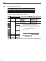
A Brake Control Commands. . . . . . . . . . . . . . . . . . . . . . . . . . . . . . . . . . . . . . . . .A-2
B General-purpose Servo Control Command . . . . . . . . . . . . . . . . . . . . . . . . . . .A-4
C Latch Function . . . . . . . . . . . . . . . . . . . . . . . . . . . . . . . . . . . . . . . . . . . . . . . . .A-6
Revision History
vi
1
MECHATROLINK-II Commands
This chapter provides on outline of MECHATROLINK-II commands.
1.1 MECHATROLINK-II Communications . . . . . . . . . . . . . . . . . . . . . . . . . . . . 1-2
1.1.1
1.1.2
1.1.3
1.1.4
Layers . . . . . . . . . . . . . . . . . . . . . . . . . . . . . . . . . . . . . . . . . . . . . . . . . . . . . . . . . . . . . 1-2
Frame Structure . . . . . . . . . . . . . . . . . . . . . . . . . . . . . . . . . . . . . . . . . . . . . . . . . . . . . 1-2
State Transition Diagram . . . . . . . . . . . . . . . . . . . . . . . . . . . . . . . . . . . . . . . . . . . . . . . 1-3
Terminology . . . . . . . . . . . . . . . . . . . . . . . . . . . . . . . . . . . . . . . . . . . . . . . . . . . . . . . . . 1-4
1.2 MECHATROLINK-II Command List . . . . . . . . . . . . . . . . . . . . . . . . . . . . . 1-5
1.3 Command and Response Timing . . . . . . . . . . . . . . . . . . . . . . . . . . . . . . . 1-8
1.3.1 Command Data Execution Timing . . . . . . . . . . . . . . . . . . . . . . . . . . . . . . . . . . . . . . . . 1-8
1.3.2 Monitored Data Input Timing . . . . . . . . . . . . . . . . . . . . . . . . . . . . . . . . . . . . . . . . . . . . 1-8
1.4 Data Order . . . . . . . . . . . . . . . . . . . . . . . . . . . . . . . . . . . . . . . . . . . . . . . . 1-9
MECHATROLINK-II Commands
1.2.1 Main Commands (In command code order) . . . . . . . . . . . . . . . . . . . . . . . . . . . . . . . . 1-5
1.2.2 Subcommands (In command code order) . . . . . . . . . . . . . . . . . . . . . . . . . . . . . . . . . . 1-6
1.2.3 Combination of MECHATROLINK-II Main Commands and Subcommands . . . . . . . . 1-7
1
1-1
1 MECHATROLINK-II Commands
1.1.1 Layers
1.1
MECHATROLINK-II Communications
1.1.1
Layers
The MECHATROLINK-II communications layers have functions equivalent to layers 1, 2, and 7 in the OSI
(Open System Interconnection) reference model.
OSI Reference Model and MECHATROLINK-II Model
OSI
MECHATROLINK-II
Layer 7: Application layer
MECHATROLINK-II application layer
Layers 3 to 6
None
Layer 2: Data link layer
MECHATROLINK-II data link layer
Layer 1: Physical layer
MECHATROLINK-II physical layer
This manual describes commands for the application layer.
1.1.2
Frame Structure
A MECHATROLINK-II command is composed of a main command and a subcommand as shown below. It
can also be used only with a main command.
Byte
0
1
Control
field
16 17
Main command area
29 30 31
Subcommand area
Information field
Classification
Byte
Command
Response
Control
Field
0
03H (Fixed)
01H (Fixed)
1 to 16 Used by main command.
InformaUsed by subcommands. The subcommands for servo drives use only 17th to 29th byte. Therefore,
tion
17 to 31 only 17th to 29th byte are described in this manual.
Field
Note: In some main commands, subcommand cannot be used.
The application layer interfaces with only the information field.
1-2
1.1 MECHATROLINK-II Communications
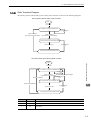
State Transition Diagram
The primary (master) and secondary (slave) station state transitions are shown in the following diagrams.
Primary Station (Master Station) State Transition
Start
Power ON
P1/ Waits for connection establishment
Communications
error
Sends CONNECT
(Synchronous communications)
Sends CONNECT
(Asynchronous communications)
P2/ Asynchronous communications state
Communications
error
Sends SYNC_SET
P3/ Synchronous communications state
Secondary Station (Slave Station) State Transition
Start
Power ON
P1/ Waits for connection establishment
Communications
error
Sends CONNECT
(Asynchronous communications)
Receives DISCONNECT
Communications
error
Receives CONNECT
P2/ Asynchronous communications state
Receives DISCONNECT
Communications
error
Sends SYNC_SET
MECHATROLINK-II Commands
1.1.3
1
P3/ Synchronous communciations state
Phase
Abbreviation
Description
1
P1
Waiting for establishment of connection.
2
P2
Asynchronous communications enabled. Only asynchronous commands can be used.
3
P3
Synchronous communications enabled. Both synchronous and asynchronous commands
can be used.
1-3
1 MECHATROLINK-II Commands
1.1.4 Terminology
1.1.4
Terminology
This section defines the terminology used in this manual.
(1) Transmission Cycle and Communications Cycle
Transmission Cycle:
The transmission cycle is the cycle in the MAC (Media Access Control) layer. It is the communications cycle
for physically sending data to the transmission path.
The transmission cycle is unaffected by the services provided by the application layer.
Communications Cycle:
The communications cycle is the cycle for application layer. The communications cycle is set to an integral
multiple of the transmission cycle.
(2) Synchronization Classification
MECHATROLINK-II commands include both synchronous and asynchronous commands.
• Synchronous Commands (Classification S):
For commands of this type, commands are sent and response are received every communications cycle.
A response to a command that has been sent to a slave station is received at the next communications cycle.
The WDT (Watchdog Timer) in the frames are refreshed and checked every communications cycle. Synchronous commands can be used only during synchronous communications (Phase 3).
• Asynchronous Commands (Classification A):
For commands of this type, commands are sent asynchronously to the communications cycle.
Subsequent commands can be sent after confirming the completion of processing of the slave station that
received the command.
The WDT (Watchdog Timer) in the frames are not checked.
1-4
1.2 MECHATROLINK-II Command List
1.2
MECHATROLINK-II Command List
1.2.1
Main Commands (In command code order)
The MECHATROLINK-II main commands used for Σ-V series servodrives are listed below.
Command
00H
NOP
01H
02H
Function
Reference
Nothing is performed.
3.1
PRM_RD
Reads the specified parameter.
3.13
PRM_WR
Saves the specified parameter.
3.6
03H
ID_RD
Reads the device ID.
3.5
04H
CONFIG
Enables the current parameter settings.
3.8
05H
ALM_RD
Reads the current alarm or warning status, and the alarm history.
3.15
06H
ALM_CLR
Clears the current alarm or warning status, and the alarm history.
3.16
0DH
SYNC_SET
Starts synchronous communications.
3.4
0EH
CONNECT
Requests to establish a MECHATROLINK connection.
3.3
0FH
DISCONNECT
Requests to releases connection.
3.2
1CH
PPRM_WR
Saves the parameters in non-volatile memory.
3.7
20H
POS_SET
Sets the coordinates.
3.17
23H
SENS_ON
Turns the encoder power supply on, and gets the position data.
3.9
24H
SENS_OFF
Turns the encoder power supply off.
3.11
25H
HOLD
From current motion status, performs a deceleration stop and positioning
according to the deceleration value set in the parameter.
4.1
28H
LTMOD_ON
Enables the position data latch by the external signal input.
4.2
29H
LTMOD_OFF
Disables the position data latch by the external signal input.
4.3
30H
SMON
Monitors the SERVOPACK status.
3.14
31H
SV_ON
Turns the servo of the motor on.
3.10
32H
SV_OFF
Turns the servo of the motor off.
3.12
34H
INTERPOLATE
Starts interpolation feeding.
4.4
35H
POSING
Starts positioning to the target position (TPOS) at the target speed
(TSPD).
4.5
36H
FEED
Starts constant speed feeding at the target speed (TSPD)
4.6
38H
LATCH
Performs interpolation feeding and latches the position using the specified
latch signal.
4.7
39H
EX_POSING
Moves toward the target position (TPOS) at the target speed (TSPD).
When a latch signal is input midway, positioning is performed according
to the final travel distance for external position specified in the parameter
from the latch signal input position.
4.8
3AH
ZRET
Performs a homing.
4.9
3CH
VELCTRL
Controls speed.
4.10
3DH
TRQCTRL
Controls torque (force).
4.11
3EH
ADJ
Used to monitor and adjust data for maintenance.
3.18
MECHATROLINK-II Commands
Command
Code
1
1-5
1 MECHATROLINK-II Commands
1.2.2 Subcommands (In command code order)
1.2.2
Subcommands (In command code order)
The MECHATROLINK-II subcommands used for Σ-V series servodrives are listed below.
Command
Code
1-6
Command
Function
Reference
00H
NOP
Same function as of the main command NOP
6.1
01H
PRM_RD
Same function as of the main command PRM_RD
6.2
02H
PRM_WR
Same function as of the main command PRM_WR
6.3
05H
ALM_RD
Same function as of the main command ALM_RD
6.4
1CH
PPRM_WR
Same function as of the main command PPRM_WR
6.5
28H
LTMOD_ON
Same function as of the main command LTMOD_ON
6.6
29H
LTMOD_OFF
Same function as of the main command LTMOD_OFF
6.7
30H
SMON
Same function as of the main command SMON
6.8
1.2 MECHATROLINK-II Command List
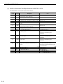
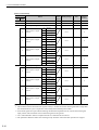
Combination of MECHATROLINK-II Main Commands and Subcommands
Subcommands can be used by combining as listed below.
CODE
Maine
Command
Subcommand
NOP
PRM_WR ALM_RD
PPRM_
WR
LTMOD_
ON
LTMOD_
OFF
SMON
00
NOP
OK
OK
OK
OK
OK
OK
OK
01
PRM_RD
OK
NG
NG
NG
NG
NG
OK
02
PRM_WR
OK
NG
NG
NG
NG
NG
OK
03
ID_RD
OK
OK
OK
OK
OK
OK
OK
04
CONFIG
OK
NG
NG
NG
NG
NG
OK
05
ALM_RD
OK
NG
NG
NG
NG
NG
OK
06
ALM_CLR
OK
NG
NG
NG
NG
NG
OK
0D
SYNC_SET
OK
NG
NG
NG
NG
NG
OK
0E
CONNECT
OK
NG
NG
NG
NG
NG
NG
0F
DISCONNECT
OK
NG
NG
NG
NG
NG
NG
1C
PPRM_WR
OK
NG
NG
NG
NG
NG
OK
20
POS_SET
OK
NG
NG
NG
NG
NG
OK
23
SENS_ON
OK
NG
NG
NG
NG
NG
OK
24
SENS_OFF
OK
NG
NG
NG
NG
NG
OK
25
HOLD
OK
OK
OK
OK
OK
OK
OK
28
LTMOD_ON
OK
NG
NG
NG
NG
NG
OK
29
LTMOD_OFF
OK
NG
NG
NG
NG
NG
OK
30
SMON
OK
OK
OK
OK
OK
OK
OK
31
SV_ON
OK
OK
OK
OK
OK
OK
OK
32
SV_OFF
OK
OK
OK
OK
OK
OK
OK
34
INTERPOLATE
OK
OK
OK
OK
OK
OK
OK
35
POSING
OK
OK
OK
OK
OK
OK
OK
36
FEED
OK
OK
OK
OK
OK
OK
OK
38
LATCH
OK
OK
OK
OK
NG
NG
OK
39
EX_POSING
OK
OK
OK
OK
NG
NG
OK
3A
ZRET
OK
OK
OK
OK
NG
NG
OK
3C
VELCTRL
OK
OK
OK
OK
OK
OK
OK
3D
TRQCTRL
OK
OK
OK
OK
OK
OK
OK
3E
ADJ
OK
NG
NG
NG
NG
NG
OK
MECHATROLINK-II Commands
1.2.3
1
Note: OK: Can be combined, NG: Cannot be combined
1-7
1 MECHATROLINK-II Commands
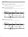
1.3.1 Command Data Execution Timing
1.3
Command and Response Timing
This section describes command execution timing at a slave station and monitored data input timing at the
master station.
These timings are constant, regardless of the transmission cycle and communications cycle.
1.3.1
Command Data Execution Timing
Motion commands (such as POSING and INTERPOLATE) and the OPTION in the command data field are
executed 312.5 µs after they are received.
Response
Command
Transmission cycle
Master sends
Slave sends
Received
Sent
312.5 µs until the motor starts running
1.3.2
Monitored Data Input Timing
The monitor, I/O, and status data are the data of 312.5 µs before the response is sent.
Command
Response
Transmission cycle
Master sent
Slave sent
Received
Sent
Position and signal data 312.5 µs before
1-8
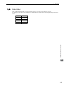
1.4 Data Order
Data Order
Data in MECHATROLINK-II commands and responses is stored in little endian byte order.
For example, 4-byte data “0x1234ABCD” in hexadecimal is stored from the least significant byte as shown
below.
Byte
Data
1
CD
2
AB
3
34
4
12
MECHATROLINK-II Commands
1.4
1
1-9
2
Operation Sequence
This chapter describes basic operation sequences through MECHATROLINK-II communications.
2.1 Preparing for Operation . . . . . . . . . . . . . . . . . . . . . . . . . . . . . . . . . . . . . . 2-2
2.1.1 Setting MECHATROLINK-II Communications . . . . . . . . . . . . . . . . . . . . . . . . . . . . . . . 2-2
2.1.2 Checking the Communications Status . . . . . . . . . . . . . . . . . . . . . . . . . . . . . . . . . . . . 2-2
2.2 Operation Sequence for Managing Parameters Using a Controller . . . . . 2-3
2.3 Operation Sequence for Managing Parameters Using a SERVOPACK . . 2-4
2.3.1 Setup Sequence . . . . . . . . . . . . . . . . . . . . . . . . . . . . . . . . . . . . . . . . . . . . . . . . . . . . . 2-4
2.3.2 Ordinary Operation Sequence . . . . . . . . . . . . . . . . . . . . . . . . . . . . . . . . . . . . . . . . . . 2-4
2.4.1
2.4.2
2.4.3
2.4.4
2.4.5
Operation Sequence When Turning the Servo ON . . . . . . . . . . . . . . . . . . . . . . . . . . . 2-5
Operation Sequence When OT (Overtravel Limit Switch) Signal Is Input . . . . . . . . . . 2-5
Operation Sequence at Emergency Stop (Main Circuit OFF) . . . . . . . . . . . . . . . . . . . 2-5
Operation Sequence When a Safety Signal is Input . . . . . . . . . . . . . . . . . . . . . . . . . . 2-6
Operation Sequence At Occurrence of Alarm . . . . . . . . . . . . . . . . . . . . . . . . . . . . . . . 2-6
2.5 Setting the Origin Before Starting Operation . . . . . . . . . . . . . . . . . . . . . . . 2-8
2.5.1 When Using an Incremental Encoder . . . . . . . . . . . . . . . . . . . . . . . . . . . . . . . . . . . . . 2-8
2.5.2 When Using an Absolute Encoder . . . . . . . . . . . . . . . . . . . . . . . . . . . . . . . . . . . . . . . 2-8
Operation Sequence
2.4 Specific Operation Sequences . . . . . . . . . . . . . . . . . . . . . . . . . . . . . . . . . 2-5
2
2-1
2 Operation Sequence
2.1.1 Setting MECHATROLINK-II Communications
2.1
Preparing for Operation
This section describes how to set communications specifications before starting communications, and how to
confirm the communications status.
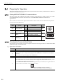
2.1.1
Setting MECHATROLINK-II Communications
The rotary switch (SW1) and DIP switch (SW2), which are located near the top under the front cover of Σ-V
series SERVOPACK, are used as shown below to set the MECHATROLINK-II communications
specifications.
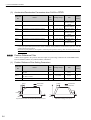
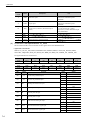
SW1 is used to set the lowermost digit of station address. SW2 is used to set the communications specifications as shown in the table below.
SW2
Function
Setting
Description
OFF
4 Mbps (MECHATROLINK-I)
ON
10 Mbps (MECHATROLINK-II)
Pin 1
Sets the baud rate.
Pin 2
Sets the number of
transmission bytes.
OFF
17 bytes
ON
32 bytes
Pin 3
Sets the station
address.
OFF
Station address = 40H+SW1
ON
Station address = 50H+SW1
Factory
setting
2
3 4 5
1
0
F
ON
6
7
8
9
A
E
D C B
ON
SW1(factory setting)
OFF
ON
OFF
Pin 4
2.1.2
Reserved.
(Do not change.)
OFF
−
OFF
1
2
3
4
SW2(factory settings)
Checking the Communications Status
Turn ON the control and main circuit power supplies and use the following procedure to confirm that the SERVOPACK is ready for communications.
(1) Operation Procedure
Procedure
Operation
1
Confirm that the wiring is correctly made.
2
Turn ON the SERVOPACK control and main circuit power supplies.
When the control power is being normally supplied to the SERVOPACK, POWER LED on the SERVOPACK is lit.
When the main circuit power supply is ON, CHARGE is lit.
3
Turn ON the controller power supply and start MECHATROLINK communications.
4
Check the communications status.
When communications in the data link layer have started, COM LED on the SERVOPACK is lit.
Note: If COM LED is not lit, check the communications settings of SW1, SW2, and the controller, and then
turn the power supplies OFF and ON again.
When the MECHATROLINK-II connection in the application layer is established, the 7-segment LED indicates the completion of CONNECT execution as shown below.
When lit: CONNECT execution completed
When unlit: CONNECT execution not completed
2-2
2.2 Operation Sequence for Managing Parameters Using a Controller
Operation Sequence for Managing Parameters Using a
Controller
When the parameters are managed by a controller, the parameters are automatically transmitted from the controller to the SERVOPACK when the power is turned ON. Therefore, the settings of SERVOPACK do not
need to be changed when the SERVOPACK is replaced.
Procedure
1
∗
Operation
Command to Send
Turn on the control and main circuit power supplies.
NOP
2
Reset the previous communications status.
DISCONNECT*
3
Establish communications connection and starts WDT count.
CONNECT
4
Check information such as device ID.
ID_RD
5
Get device setting data such as parameters.
PRM_RD, ADJ
6
Set the parameters required for device.
PRM_WR
7
Enable the parameter settings (Setup).
CONFIG
8
Turn the encoder power supply to the position data.
SENS_ON
9
Turn the servo on.
SV_ON
10
Start operation.
11
Turn the servo off.
SV_OFF
12
Disconnect the communications connection.
DISCONNECT
13
Turn the control and main circuit power supplies.
–
If the connection cannot be released normally, send DISCONNECT command for 2 or more communications cycles,
and then send CONNECT command.
Operation Sequence
2.2
2
2-3
2 Operation Sequence
2.3.1 Setup Sequence
2.3
Operation Sequence for Managing Parameters Using a
SERVOPACK
To manage the parameters by using SERVOPACK’s non-volatile memory, save the parameters in the non-volatile memory at setup and use an ordinary operation sequence.
2.3.1
Setup Sequence
Procedure
∗
2.3.2
Operation
1
Turn on the control and main circuit power supply.
NOP
2
Reset the previous communications status.
DISCONNECT*
3
Establish communications connection and start WDT count.
CONNECT
4
Check information such as device ID.
ID_RD
5
Get device setting data such as parameters.
PRM_RD, ADJ
6
Save the parameters required for device in the non-volatile
memory.
PPRM_WR
Note: Do not use PRM_WR.
7
Disconnect the communications connection.
DISCONNECT
8
Turn off the control and main circuit power supplies.
–
If the connection cannot be released normally, send a DISCONNECT command for 2 or more communications cycles,
and then send a CONNECT command.
Ordinary Operation Sequence
Procedure
∗
2-4
Command to Send
Operation
Command to Send
1
Turn on the control and main circuit power supplies.
NOP
2
Reset the previous communications status.
DISCONNECT*
3
Establish communications connection and start WDT count.
CONNECT
4
Check information such as device ID.
ID_RD
5
Get device setting data such as parameters.
PRM_RD, ADJ
6
Turn on the encoder power supply to get the position data.
SENS_ON
7
Turn the servo on.
SV_ON
8
Start operation.
POSING, INTERPOLATE, etc.
9
Turn the servo off.
SV_OFF
10
Disconnect the communications connection.
DISCONNECT
11
Turn off the control and main circuit power supplies.
–
If the connection cannot be released normally, send a DISCONNECT command for 2 or more communications cycles,
and then send a CONNECT command.
2.4 Specific Operation Sequences
2.4
Specific Operation Sequences
This section describes operations that use commands in specific sequences.
2.4.1
Operation Sequence When Turning the Servo ON
Motor control using a host controller is performed using motion commands only during Servo ON (motor
power ON).
While the SERVOPACK is in Servo OFF status (while current to the motor is interrupted), the SERVOPACK
manages position data so that the reference coordinate system (POS, MPOS) and the feedback coordinate system (APOS) are equal. For correct execution of motion commands, therefore, it is necessary to use the SMON
(Status Monitoring) command after the SERVOPACK status changes to Servo ON, to read the servo reference
coordinates (POS) and send an appropriate reference position.
Confirm the following bit status before sending the SV_ON command:
STATUS field: PON = 1 and ALM = 0
IO Monitor field: HBB = 0
2.4.2
Operation Sequence When OT (Overtravel Limit Switch) Signal Is Input
When an OT signal is input, the SERVOPACK prohibits the motor from rotating in the way specified in the
parameter Pn001. The motor continues to be controlled by the SERVOPACK while its rotation is prohibited.
Procedure
Operation
1
Monitor OT signals (P_OT and N_OT of IO Monitor field). When an OT signal is input, send an appropriate stop command:
While an interpolation command (INTERPOLATE, LATCH) is being executed: Leave the interpolation
command as it is and stop updating the interpolation position. Or, send a HOLD command and SMON
command.
While a move command (such as POSING) other than interpolation commands is being executed: Send a
HOLD command.
2
Check the output completion flag DEN. If DEN = 1, the SERVOPACK completed the OT processing.
At the same time, check the flag PSET. If PSET = 1, the motor is completely stopped.
Keep the command used in procedure 1 active until both of the above flags are set to 1.
3
Use a move command such as POSING for OT cancellation (retraction) processing.
Before sending a move command, read out the current reference position (POS) and write it to reset the correct reference coordinate system for the controller.
Information: When an OT signal is input during execution of motion command ZRET or EX_POSING, the
execution of the command will be cancelled. For retraction, always send a stop command
described in procedure 1 first, and then send a retraction command (move command).
2.4.3
Operation Sequence at Emergency Stop (Main Circuit OFF)
After confirming that SV_ON or PON bit in the response data STATUS field is OFF (= 0), send an SV_OFF
command.
During emergency stop, always monitor the SERVOPACK status using a command such as the SMON (Status
Monitoring) command.
Operation Sequence
When an OT signal is input, use the following procedure to process the OT signal.
2
2-5
2 Operation Sequence
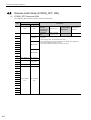
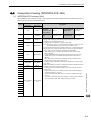
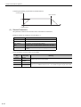
2.4.4 Operation Sequence When a Safety Signal is Input
2.4.4
Operation Sequence When a Safety Signal is Input
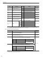
When an HWBB1 or HWBB2 signal is input while the motor is being operated, current to the motor will be
forcibly stopped, and the motor will be stopped according to the setting of the 1st digit of parameter Pn001.
[When an HWBB signal is input after the SERVOPACK stops powering the motor]
/HWBB1
/HWBB2
OFF
M-II
command
Motion command,
etc.
STATUS
field
SVON
SV_OFF
SV_ON
SV_OFF, etc.
0
1
IO Monitor
field
HBB
SERVOPACK
status
OFF
ON
0
0
1
BB status
RUN status
1
HWBB status
BB status
(baseblocked) (hard wire baseblocked)
(baseblocked)
RUN status
[When an HWBB signal is input while the SERVOPACK is powering the motor]
/HWBB1
/HWBB2
M-II
command
OFF
ON
Motion command, etc.
OFF
SV_OFF, etc
STATUS
field
SVON
1
0
IO Monitor
field
HBB
0
1
SERVOPACK
status
RUN status
SV_ON
1
0
HWBB status
BB status
(hard wire baseblocked)
(baseblocked)
RUN status
When an HWBB Signal is Input:
Monitor the HWBB input signal and SCM output signal status, or HBB signal status in IO Monitor field. If a
forced stop status is detected, send a command such as SV_OFF to stop the motor.
Restoration from Stop Status:
Reset the HWBB1 or HWBB2 signal, and then send a command other than SV_ON, such as SV_OFF. Then,
restore the controller and system. When the controller and system are restored, turn the servo ON using the
operation sequence to turn the servo ON.
Note 1. If the SERVOPACK enters HWBB status while sending an SV_ON command, reset the /HWBB1 or /HWBB2
signal and then send a command other than SV_ON, such as SV_OFF. Then, send the SV_ON command again to
restore the normal operation status.
2. If the SERVOPACK enters HWBB status during execution of an SV_OFF, INTERPOLATE, LATCH, POSING,
FEED, EX_POSING, or ZRET command, a command warning will occur since the SERVOPACK status changes
to Servo OFF status. Execute the Clear Alarm or Warning (ALM_CLR) command to restore normal operation.
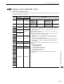
2.4.5
Operation Sequence At Occurrence of Alarm
When the ALM bit in STATUS field of response turns on (= 1), send SV_OFF command. Use ALM_RD command to check the alarm occurrence status.
To clear the alarm status, send ALM_CLR command after removing the cause of alarm. However, the alarms
that require turning the power supply off and then on again to clear the alarm status, sending ALM_CLR command will not clear the alarm status.
2-6
2.4 Specific Operation Sequences
Operation Sequence
If a communications alarm A.E5
or A.E6
occurs, send ALM_CLR command to reset the alarm and then
send SYNC_SET command.
2
2-7
2 Operation Sequence
2.5.1 When Using an Incremental Encoder
2.5
Setting the Origin Before Starting Operation
2.5.1
When Using an Incremental Encoder
When an incremental encoder is used in the slave station, carry out a homing operation after turning ON the
power supply.
After the origin is set, set the reference coordinate system to determine the work coordinate origin as required:
1. Setting the Reference Coordinate System Using ZRET Command
The master station (controller) uses ZRET command to return the slave station to the origin and sets the reference coordinate system based on the origin.
2. Setting the Reference Coordinate System Using POS_SET Command
The master station (controller) uses POS_SET command to set the reference coordinate system of the slave
station.
i) Position to the reference position.
ii) Send the POS_SET command with POS_SET_MODE.POS_SEL = APOS (= 3),
POS_SET_MODE.REFE = 1, and POS_DATA = reference position.
ZPOINT and software limits are enabled after the reference coordinate system has been set.
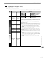
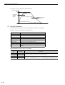
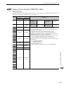
2.5.2
When Using an Absolute Encoder
When an absolute encoder is used in the slave station, SENS_ON command can be used to set the reference
coordinate system of the slave station. The reference coordinate system will be set according to the position
detected by the absolute encoder and the coordinate system offset of the encoder (i.e., the offset between the
encoder’s coordinate system and the reference coordinate system (device built-in parameter).
The relationship between the reference coordinate system (POS and APOS), the encoder’s coordinate system,
and the coordinate system offset of the encoder are shown in the following figure.
POS: Reference position
APOS: Feedback position
Reference
coordinate
system
(POS, APOS)
Encoder
coordinate
system
Current
Reference coordinate position
X
system origin
Pn808
Encoder origin
X= +Pn808
Pn808: Absolure Encoder Origin Offset
2-8
3
Commands for Preparation Process
This chapter describes the MECHATROLINK-II commands needed to prepare for operation.
3.1 No Operation (NOP: 00H) . . . . . . . . . . . . . . . . . . . . . . . . . . . . . . . . . . . . . 3-3
3.2 Release MECHATROLINK-II Connection (DISCONNECT: 0FH) . . . . . . . 3-6
3.3 Establish MECHATROLINK-II Connection (CONNECT: 0EH) . . . . . . . . . 3-7
3.4 Start Synchronous Communications (SYNC_SET: 0DH) . . . . . . . . . . . . . 3-9
3.5 Check Device ID (ID_RD: 03H) . . . . . . . . . . . . . . . . . . . . . . . . . . . . . . . 3-10
3.6 Set Parameters (PRM_WR: 02H) . . . . . . . . . . . . . . . . . . . . . . . . . . . . . . 3-12
3.8 Validate Parameters (Setup) (CONFIG: 04H) . . . . . . . . . . . . . . . . . . . . . 3-14
3.9 Turn Encoder Power Supply ON (SENS_ON: 23H) . . . . . . . . . . . . . . . . 3-15
3.10 Turn Servo ON (SV_ON: 31H) . . . . . . . . . . . . . . . . . . . . . . . . . . . . . . . 3-18
3.11 Turn Encoder Power Supply OFF (SENS_OFF: 24H) . . . . . . . . . . . . . 3-20
3.12 Turn Servo OFF (SV_OFF: 32H) . . . . . . . . . . . . . . . . . . . . . . . . . . . . . 3-21
3.13 Read Parameters (PRM_RD: 01H) . . . . . . . . . . . . . . . . . . . . . . . . . . . . 3-22
3.14 Check SERVOPACK Status (SMON: 30H) . . . . . . . . . . . . . . . . . . . . . . 3-23
Commands for Preparation Process
3.7 Set and Save Parameters in Non-volatile Memory (PPRM_WR: 1CH) . 3-13
3.15 Read Alarm or Warning (ALM_RD: 05H) . . . . . . . . . . . . . . . . . . . . . . . 3-24
3.16 Clear Warning or Alarm (ALM_CLR: 06H) . . . . . . . . . . . . . . . . . . . . . . 3-26
3
3.17 Set Coordinate System (POS_SET: 20H) . . . . . . . . . . . . . . . . . . . . . . . 3-27
3.18 Monitor and Adjust Settings (ADJ: 3EH) . . . . . . . . . . . . . . . . . . . . . . . . 3-28
3-1
3 Commands for Preparation Process
Commands for Preparation Process
Operation
3-2
Command to Send
Description
Confirmation of completion of
SERVOPACK initialization
NOP, DISCONNECT
Checks if the SERVOCK has been initialized to be ready for
communications or not.
Establishment of MECHATROLINK-II connection
CONNECT
Establishes communications connection and starts WDT
count.
Synchronous communications
start
SYNC_SET
Starts synchronous communications.
Device ID check
ID_RD
Checks information such as device ID.
Parameter setting
PRM_WR
Sets the parameters required for device. (When parameters
are managed by a controller)
Parameter setting and saving
PPRM_WR
Sets the parameters required for device and saves them in the
non-volatile memory. (When parameters are managed by
SERVOPACK.)
Validation of parameter settings
(Setup)
CONFIG
Enables the set parameters.
Encoder power supply ON
SENS_ON
Turns on the encoder power supply to get position data.
Servo ON
SV_ON
Turns the servo on.
Encoder power supply OFF
SENS_OFF
Turns off the encoder power supply off.
Servo OFF
SV_OFF
Turns the servo off.
Parameter read-out
PRM_RD
Reads active parameters.
(When parameters are managed by a controller)
SERVOPACK status monitoring
SMON
Monitors the SERVOPACK status.
Alarm and warning read-out
ALM_RD
Reads the current alarm or warning and the alarm occurrence
history.
Clearing alarm or warning status
ALM_CLR
Clears the current alarm or warning status and the alarm
occurrence history.
Coordinate system setting
POS_SET
Sets the coordinate system.
Data monitoring and adjustment
ADJ
Monitors and adjusts the set data.
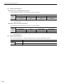
3.1 No Operation (NOP: 00H)
3.1
No Operation (NOP: 00H)
After turning on the control and main circuit power supplies, send NOP command to check if initialization of
SERVOPACK has been completed or not.
(1) No Operation (NOP: 00H)
The specifications of the NOP command are shown below.
Byte
1
NOP
Command
00H
2
00H
ALARM
3
STATUS
4
Description
Response
5
6
Phases in
which the
command can
be executed
All phases
Synchronization Asynchronous
classification
command
Processing
time
Within communications cycle
Subcommand
Can be used.
• Returns the ALM, WARNG, and CMDRDY bits in STATUS field.
Other bits will not be specified.
• The response will be NOP from the moment the power is turned on until
the initialization of SERVOPACK is completed. During this time,
CMDRY = 0.
7
8
9
10
11
12
13
14
16
WDT
RWDT
Subcommand
area
Subcommand
area
17
18
19
20
21
22
23
24
25
Commands for Preparation Process
15
26
27
3
28
29
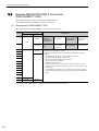
(2) ALARM
The uppermost two digits of the SERVOPACK alarm code are set in the ALARM field of the response.
For example, ALARM = 02 when a parameter checksum error 1 (A.020) occurs.
If no alarm occurs, ALARM = 00.
For details on alarms and alarm codes, refer to Σ-V Series SGM/SGDV User’s Manual Design and Maintenance MECHATROLINK-II Communications Reference/Rotary Servomotors(SIEPS80000046)/Linear Servomotors (SIEPS8000048).
3-3
3 Commands for Preparation Process
(3) Status Field Specifications
The status field is used to monitor the SERVOPACK status.
The following table shows the bit allocation in the status field.
D7
D6
D5
D4
D3
D2
D1
D0
PSET/
V_CMP
ZPOINT
–
PON
SVON
CMDRDY
WARNG
ALM
D15
D14
D13
D12
D11
D10
D9
D8
–
–
N_SOT
P_SOT
NEAR/
V_LIM
L_CMP
T_LIM
DEN/ZSPD
The following table explains each bit value and its status.
Bit
Name
Value
Description
0
No alarm
1
Alarm occurs.
0
No warning
1
Warning occurs.
0
Command cannot be received (busy).
1
Command can be received (ready).
0
Servo OFF
1
Servo ON
0
Main power supply OFF
1
Main power supply ON
0
Out of home position range
1
Within home position range
0
Out of positioning complete range
1
Within positioning complete range
(The output is completed (DEN = 1) and APOS is within the positioning
complete range.)
V_CMP
(During speed
control)
0
Speed does not coincide.
1
Speed coincides.
DEN
(During position
control)
0
During output
1
Output completed
ZSPD
(During speed
control)
0
Zero speed not detected
1
Zero speed detected
0
Not during torque (force) limit
1
During torque (force) limit
0
Latch not completed
1
Latch completed
NEAR
(During position
control)
0
Out of positioning proximity
1
Within positioning proximity
V_LIM
(During speed
control)
0
Speed limit not detected
1
Speed limit detected
0
OT signal is OFF.
1
OT signal is ON.
D0
ALM
D1
WARNG
D2
CMDRDY
D3
SVON
D4
PON
D5
D6
D7
D8
D9
D10
D11
D12
3-4
ZPOINT
PSET
(During position
control)
T_LIM
L_CMP
P_SOT
3.1 No Operation (NOP: 00H)
Bit
Name
D13
Value
N_SOT
Description
0
OT signal is OFF.
1
OT signal is ON.
D14
D15
(4) Details WDT and RWDT
The watchdog timer data will be set in WDT and RWDT of NOP command and response as shown below.
D7
WDT
SN: Copy of RSN in RWDT
D7
RWDT
D4 D3
D0
MN: Incremented by 1 each
communications cycle
D4 D3
RSN: Incremented by 1 each
communications cycle
RMN: Copy of MIN in WDT
MN: Master station watchdog timer count
D0
RSN: SERVOPACK’s watchdog timer count
Commands for Preparation Process
The watchdog timer is checked after synchronous communications has been established.
The SERVOPACK watchdog timer data will be refreshed whether synchronous communications is established
or not.
3
3-5
3 Commands for Preparation Process
3.2
Release MECHATROLINK-II Connection
(DISCONNECT: 0FH)
The connection must be released at the end of communications.
Send a DISCONNECT command to release the connection.
(1) Disconnection (DISCONNECT: 0FH)
The specifications of the DISCONNECT command are shown below.
Byte
DISCONNECT
Command
1
0FH
0FH
2
ALARM
3
STATUS
4
Description
Response
5
6
7
8
9
10
11
12
13
Phases in
which the
command can
be executed
All phases
Processing
time
Communications
cycle or more
Subcommand
(Within 5 s)
Synchronization Asynchronous
classification
command
• Releases the MECHATROLINK-II connection, and the SERVOPACK
changes communications to Phase 1.
• When this command is received, the following operations will be performed.
- The SERVOPACK changes communications to Phase 1.
- The SERVOPACK changes to Servo OFF.
- The reference point setting becomes invalid.
- The position data is initialized.
- BRAKE signal turns ON.
- If an alarm has occurred, releasing the connection will not clear the
alarm status. The set parameter data (saved in the volatile memory) will
remain valid.
- To re-establish connection, carry out operations in the same sequence
as when turning ON the power supply and set the required parameters
again.
14
15
16
WDT
RWDT
Note: Always send a DISCONNECT command for at least two communications cycles.
3-6
Cannot be used
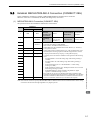
3.3 Establish MECHATROLINK-II Connection (CONNECT: 0EH)
3.3
Establish MECHATROLINK-II Connection (CONNECT: 0EH)
Send a CONNECT command to establish a MECHATROLINK-II communications connection.
When the connection is established, the WDT (watchdog timer) count starts.
(1) MECHATROLINK-II Connection (CONNECT: 0EH)
The specifications of the CONNECT command are shown below.
1
CONNECT
Command
0EH
2
0EH
ALARM
3
STATUS
4
5
VER
VER
6
COM_MOD
COM_MOD
7
COM_TIM
COM_TIM
WDT
RWDT
8
9
10
11
12
13
14
15
16
Description
Response
Phases in
which the
command can
be executed
Phase 1
Processing
time
Communications
cycle or more
Subcommand
(Within 5 s)
Synchronization Asynchronous
classification
command
Cannot be used
• Establishes a MECHATROLINK-II connection and sets the communications mode according to COM_MODE.
• VER: Version. Set VER to 21H (Version 2.1)
• COM_MOD: Sets the communications mode. Refer to (2) Details of
COM_MOD for details.
• COM_TIM: Sets the communications cycle. The communications cycle
must satisfy the following equation within the range between 1 and 32.
0.25 [ms] ≤ Transmission cycle [ms] × COM_TIM ≤ 32 [ms]
• A warning will occur and the command will be ignored in the following
cases.
- If COM_MODE is out of the setting range: Data setting warning 2
(A.94B)
- If COM_TIM is out of the settting range: Data setting warning 2
(A.94B)
- If the transmission bytes is 17 but SUBCMD = 1: Data setting
warning 2 (A.94B)
- If the transmission speed is set to 10 Mbps but VER is not set to 21H:
Data setting warning 2 (A.94B)
- If the SERVOPACK is being operated by SigmaWin or digital
operator: Command warning 1 (A.95A)
• Slave stations will not accept commands other than CONNECT, DISCONNECT, and NOP before the connection is established. If a command
other than CONNECT, DISCONNECT, and NOP is sent before the connection is established, NOP is always returned as the response.
Note: Slave stations will not accept any MECHATROLINK-II command while a motion command such as JOG is being
executed to run the motor through SigmaWin or by digital operator.
Commands for Preparation Process
Byte
3
3-7
3 Commands for Preparation Process
(2) Details of COM_MOD
COM_MOD bit allocation and each bit status are described below.
D7
D6
D5
D4
SUBCMD
0
0
0
D3
D2
DTMOD
D1
D0
SYNCMOD
0
• SYNCMOD: Sets the synchronization mode.
SYNCMOD = 0: Asynchronous communications
SYNCMOD = 1: Synchronous communications
• DTMOD: Sets the data transmission method.
DTMOD = 00 or 11: Single transmission
DTMOD = 01: Continuous transmission
Normally, set DTMOD to 00.
• SUBCMD: Specify whether to use subcommands or not.
SUBCMD = 0: Do not use subcommands
SUBCMD = 1: Use subcommands
Note: When SYNCMOD = 0, it is necessary to send SYNC_SET command to enter Phase 3.
Warning
Phase 1
SYNCMOD = 0
Phase 2
SYNCMOD = 1
SYNC_SET
Phase 3 (3) Transmission Cycle and Communications Cycle
The table below provides the applicable communications cycle and the maximum number of connectable stations for each transmission cycle setting.
Transmission Bytes
Transmission Cycle
Applicable Communications Cycle
17-byte
32-byte
Connectable Max. Number of Stations
0.25 ms
0.25 ms to 8.00 ms (in 0.25-ms units)
2
1
0.50 ms
0.50 ms to 16.00 ms (in 0.50-ms units)
7
4
0.75 ms
0.75 ms to 24.00 ms (in 0.75-ms units)
11
7
1.00 ms
1.00 ms to 32.00 ms (in 1.00-ms units)
15
9
1.50 ms
1.50 ms to 32.00 ms (in 1.50-ms units)
23
15
2.00 ms
2.00 ms to 32.00 ms (in 2.00-ms units)
30
21
2.50 ms
2.50 ms to 2.00 ms (in 2.50-ms units)
30
26
3.00 ms
3.00 ms to 32.00 ms (in 3.00-ms units)
30
30
3.50 ms
3.50 ms to 32.00 ms (in 3.50-ms units)
30
30
4.00 ms
4.00 ms to 32.00 ms (in 4.00-ms units)
30
30
Note: Communications retry stations can be connected as long as the total number of connected stations, including the
retry stations, is within the connectable max. number of stations. The maximum number of retry stations is the difference between the connectable max. number of stations and the number of actually connected slave stations, but
limited to 7.
Note that the connectable max. number of stations may differ depending on the controller specifications.
3-8
3.4 Start Synchronous Communications (SYNC_SET: 0DH)
3.4
Start Synchronous Communications (SYNC_SET: 0DH)
This section describe how to start synchronization to change a communications phase from phase 2 to phase 3.
When SYNCMOD bit of the COM_MOD of CONNECT command is set to 1, the communications phase will
change from phase 1 to phase 3 at the moment the connection is established. In this case, it is not necessary to
send a SYNC_SET command.
(1) Start Synchronous Communications (SYNC_SET: 0DH)
The specifications of the SYNC_SET command are described below.
1
SYNC_SET
Command
0DH
2
0DH
ALARM
3
STATUS
4
5
6
7
8
9
10
11
12
13
14
15
16
WDT
Description
Response
RWDT
Phases in
which the
command can
be executed
Phase 2
Processing
time
Communications
cycle or more
Subcommand
(Within 5 s)
Synchronization Asynchronous
classification
command
Cannot be used
• Starts synchronous communications. Switched from phase 2 to phase 3.
• Synchronization is made at the WDT changing edge. However, if WDT
errors are masked by parameter Pn800.0, processing is completed when
this command is received.
• During phase 3, the slave ignores this command and returns a normal
response without a warning.
• If the slave station in Servo ON status receives this command in phase 2,
the slave station enters Servo OFF status.
• At occurrence of the following alarms and warnings, this command must
be transmitted to restart synchronous communications.
- Command warning 1 (A.95A) occurs when this command is used in
phase 1
- MECHATROLINK-II synchronization Error (A.E50)
- MECHATROLINK-II synchronization failed (A.E51)
- MECHATROLINK-II Communications Error (A.E60)
- MECHATROLINK-II Transmission Cycle Error (A.E61)
- Command warning 1 (A.95A) occurs when this command is used while
operating the servo using SigmaWin or a digital operator
Commands for Preparation Process
Byte
3
3-9
3 Commands for Preparation Process
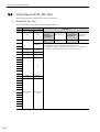
3.5
Check Device ID (ID_RD: 03H)
Send ID_RD command to read the device ID for confirmation.
(1) Read ID (ID_RD: 03H)
The specifications of the ID_RD command are described below.
Byte
ID_RD
Command
1
03H
2
03H
ALARM
3
STATUS
4
5
DEVICE_
CODE
DEVICE_
CODE
6
OFFSET
OFFSET
7
SIZE
SIZE
8
9
10
11
ID
12
13
14
15
16
WDT
RWDT
Subcommand
area
Subcommand
area
17
18
19
20
21
22
23
24
25
26
27
28
29
3-10
Description
Response
Phases in
which the
command can
be executed
Phase 2 and 3
Synchronization Asynchronous
classification
command
Processing
time
Within communications cycle
Subcommand
•
•
•
•
Can be used
Reads the device ID for contirmation.
Use DEVICE_CODE to specify the device ID to be read.
Use OFFSET to specify which data of the device ID is to be read out.
Use SIZE to specify the number of data (bytes) to be read out.
3.5 Check Device ID (ID_RD: 03H)
(2) Device ID Specifications
The specifications of the device ID are described below.
ID Data
OFFSET
Device Type/Name
00 01 02 03 04 05 06 07 08 09 0A 0B 0C 0E 0D 0F 10 11 12 13 14
DEVICE_
CODE
Servomotor
External
Encoder
Safety Option
Unit
Feedback
Option Unit
00H
Software
version
02H
Model
20H
Encoder
software
version
12H
Model
30H
Software
version
32H
Model
60H
Software
version
62H
Model
70H
Software
version
72H
S
G
D
∗
1
–
∗
2
∗
∗
∗
∗
∗
∗
∗
M
∗7
∗7
–
∗8
∗8
∗9
∗10
∗11
∗12
∗13
2
2
3
4
4
4
5
∗
6
∗
6
∗
6
∗
6
∗
6
∗
6
∗
6
00
Ver.
S
G
00
Ver.
Ver.
Ver.
Ver.
• SERVOPACK Model
*1: Model code, *2: Current capacity, *3: Power supply voltage specifications, *4: Interface specifications,
*5: Design revision order, *6: Options
• Servomotor Model
*7: Model code, *8: Rated output, *9: Power supply voltage, *10: Encoder type, *11: Design revision order,
*12: Shaft-end specifications, *13: Options
• Software version is binary data.
• Model is expressed in ASCII code and “00 (NULL)” is added at the end of each character string.
• 50H and 52H of DEVICE_CODE are reserved for system.
• When the Safety Option unit or/and Feedback Option unit are not connected, 0 is set to all the ID data.
• For an external encoder, the ID of the encoder connected to the Feedback Option unit is set.
(Therefore, 0 is set to all the ID data when no Feedback Option unit is connected.)
• When an encoder option for fully-closed loop control is connected to the Feedback Option unit, 0 is set to all
the ID data of Feedback Option unit.
Commands for Preparation Process
SERVOPACK
Model
3
3-11
3 Commands for Preparation Process
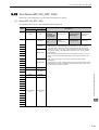
3.6
Set Parameters (PRM_WR: 02H)
Send PRM_WR command to set parameters when parameters are managed by a controller.
Parameters will be set without being saved in the non-volatile memory of SERVOPACK.
(1) Write Parameter (PRM_WR: 02H)
The specifications of the PRM_WR command are described below.
Byte
PRM_WR
Command
1
02H
2
3
4
5
6
7
8
9
10
11
12
13
14
Description
Response
02H
ALARM
Phases in
which the
command can
be executed
Phase 2 and 3
Synchronization Asynchronous
classification
command
Processing
time
Within 200 ms
Subcommand
• Writes parameters.
The parameters will not be saved in the non-volatile memory.
• For parameters that require turning the power supply OFF and ON again
to be validated, it is necessary to send a CONFIG command to validate
NO
NO
the settings.
• Use NO to specify the parameter to be written.
SIZE
SIZE
• Use SIZE to specify the number of data (bytes) of the parameter to be
written.
• PARAMETER is the data to be written.
• A warning will occur and the command will be ignored in the following
cases.
- When editing using SigmaWin or a digital operator: Command warning
1 (A.95A)
PARAMETER PARAMETER
- NO is set out of the range: Data setting warning 1 (A.94A)
- SIZE does not match: Data setting warning 4 (A.94D)
- PARAMETER is out of the range: Data setting warning 2 (A.94B)
STATUS
15
16
WDT
RWDT
• Example of NO
For the parameter Pn80D, the data is set in little endian as shown below.
3-12
Cannot be used
Byte
Data
5
0D
6
08
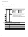
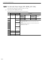
3.7 Set and Save Parameters in Non-volatile Memory (PPRM_WR: 1CH)
3.7
Set and Save Parameters in Non-volatile Memory
(PPRM_WR: 1CH)
Send a PPRM_WR command to save parameters in the SERVOPACK.
(1) Write Non-volatile Parameter (PPRM_WR: 1CH)
The specifications of the PPRM-WR command are described below.
Byte
1
PPRM_WR
Command
1CH
2
STATUS
4
5
6
7
1CH
ALARM
3
NO
NO
SIZE
SIZE
8
9
10
11
12
Description
Response
Phases in
which the
command can
be executed
Phase 2 and 3
Synchronization Asynchronous
classification
command
Processing
time
Within 200 ms
Subcommand
Cannot be used
• Saves parameters in the non-volatile memory.
• For parameters that require turning the power supply OFF and ON again
to be validated, it is necessary to send a CONFIG command to validate
the settings.
• A warning will occur and the command will be ignored in the following
cases.
- NO is out of the range: Data setting warning 1 (A.94A)
- SIZE does not match: Data setting warning 4 (A.94D)
- PARAMETER is out of the range: Data setting warning 2 (A.94B)
- While editing using SigmaWin or a digital operator: Command warning 1 (A.95A)
PARAMETER PARAMETER
13
15
16
WDT
RWDT
Do not turn off the power supply while the parameter is being written (CMDRDY = 0).
Commands for Preparation Process
14
3
3-13
3 Commands for Preparation Process
3.8
Validate Parameters (Setup) (CONFIG: 04H)
The set parameters need to be validated (setup) using a CONFIG command.
Executing this command recalculates all currently set parameters and initializes positions, output signals, etc.
(1) Set Up Device (CONFIG: 04H)
The specifications of the CONFIG command are described below.
Byte
CONFIG
Command
Response
04H
04H
1
2
ALARM
3
STATUS
4
5
6
7
8
9
Description
Phases in
which the
command can
be executed
Phase 2 and 3
Synchronization Asynchronous
classification
command
Processing
time
Within 5 s
Subcommand
Cannot be used
• Recalculates all currently set parameters and initializes position, etc.
• The SERVOPACK will change to Servo OFF if this command is received
when the SERVOPACK is Servo ON.
• The command warning 1 (A.95A) will occur and the command will be
ignored if this command is sent:
- When editing using SigmaWin or a digital operator
• Refer to (2) Status and Output Signal during CONFIG Command Executionfor details on status and output signal during CONFIG command execution.
10
11
12
13
14
15
16
WDT
RWDT
(2) Status and Output Signal during CONFIG Command Execution
The status and output signal during CONFIG command execution are listed below.
Status and Output Signal
3-14
Before CONFIG
During CONFIG
After CONFIG
ALM (status)
Current status
Current status
Current status
CMDRDY (status)
1
0
1
Other status
Current status
Not specified
Current status
ALARM (code)
Alarm currently occurred
Alarm currently occurred
Alarm currently occurred
ALM (CN1 output signal)
Current status
Current status
Current status
/S-RDY (CN1 output signal) Current status
OFF
Current status
Other output signals
Not specified
Current status
Current status
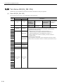
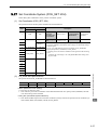
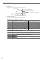
3.9 Turn Encoder Power Supply ON (SENS_ON: 23H)
3.9
Turn Encoder Power Supply ON (SENS_ON: 23H)
Send SENS_ON command to turn ON the encoder power supply.
(1) Turn Sensor ON (SENS_ON: 23H)
The specifications of the SENS_ON command are described below.
Byte
1
SENS_ON
Command
23H
23H
2
ALARM
3
STATUS
4
5
6
MONITOR1
7
Description
Response
Phases in
which the
command can
be executed
Phase 2 and 3
Synchronization Asynchronous
classification
command
Processing
time
Within 2 s
Subcommand
Cannot be used
• Obtains the initial position data and creates the present position when an
absolute encoder is used.
• The reference point, home position (ZPOINT), and software limits will
be enabled when an absolute encoder is used.
• After having used this command, the position data must be monitored
and the coordinate system of host controller must be setup.
8
9
10
MONITOR2
11
12
SEL_MON1/2
14
IO_MON
15
16
SEL_MON1/2
WDT
RWDT
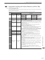
(2) Monitor Selection and Monitor Information Field Specifications: SEL_MON1/2/3/4,
MONITOR 1/2/3/4
The monitor selection and monitor information (SEL_MON1/2/3/4, MONITOR1/2/3/4) field is used to select
the Servo monitor information.
• Setting Method:
Set MONITOR 1/2/3/4 monitor codes in SEL_MON1/2/3/4 allocated in the thirteenth byte of the main command or in the reserved area of the nineteenth byte of the subcommand.
SEL_MON1/2/3/4 allocation is shown below.
D7
D6
D5
D4
D3
SEL_MON2
D7
D6
D5
SEL_MON4
D2
D1
D0
Commands for Preparation Process
13
3
SEL_MON1
D4
D3
D2
D1
D0
SEL_MON3
3-15
3 Commands for Preparation Process
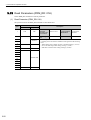
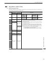
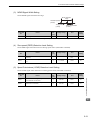
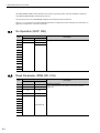
(3) Monitor Information Field Specifications: MONITOR 1/2/3/4
The MONITOR 1/2/3/4 monitor codes are listed below.
Monitor
Code
Name
0
POS
1
MPOS
Reference position
Reference unit
2
PERR
Position error
Reference unit
3
APOS
Feedback position in machine coordinate system
Reference unit
4
LPOS
Feedback latch position in machine coordinate
system
Reference unit
5
IPOS
Reference position in reference coordinate system
Reference unit
(position before reference filtering)
6
TPOS
Target position in reference coordinate system
Reference unit
Description
Unit
Reference position in reference coordinate system
Reference unit
(position after reference filtering)
7
8
FSPD
Feedback speed
Position/torque (force) control: reference
units/s
Speed control: Maximum speed/
40000000H
9
CSPD
Reference speed
Position control: Reference units/s
Speed control: Maximum speed/
40000000H
A
TSPD
Target speed
Position control: Reference units/s
Speed control: Maximum speed/
40000000H
TRQ
Torque (force) reference (The rated torque is
100%.)
Position/speed control:
% (The rated torque is 100%.)
Torque (force) control: Maximum torque
(force)/40000000H
B
C
D
3-16
E
OMN1
Option monitor 1 selected in Pn824
F
OMN2
Option monitor 2 selected in Pn825
3.9 Turn Encoder Power Supply ON (SENS_ON: 23H)
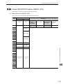
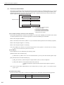
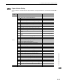
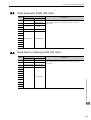
(4) IO Monitor Field Specifications: IO_MON
The IO monitor field is used to monitor the I/O signal status of the SERVOPACK.
D7
D6
D5
D4
D3
D2
D1
D0
EXT2
EXT1
PC
PB
PA
DEC
N_OT
P_OT
D15
D14
D13
D12
D11
D10
D09
D08
IO15
IO14
IO13
IO12
–
HBB
BRK
EXT3
Bit
Name
Contents
D0
P_OT
Forward run prohibited input
D1
N_OT
Reverse run prohibited input
D2
DEC
Homing deceleration LS input
D3
PA
Encoder phase A input
D4
PB
Encoder phase B input
D5
PC
Encoder phase C input
D6
EXT1
First external latch signal input
D7
EXT2
Second external latch signal input
D8
EXT3
Third external latch signal input
D9
BRK
Brake output
HBB
Stop signal input, OR of HWBB1 signal and HWBB2 signal
D10
D11
D12
D13
Reserved
IO12
IO13
CN1 input signal selected in Pn81E.0
CN1 input signal selected in Pn81E.1
D14
IO14
CN1 input signal selected in Pn81E.2
D15
IO15
CN1 input signal selected in Pn81E.3
Value
Status
0
OFF
1
ON
0
OFF
1
ON
0
OFF
1
ON
0
OFF
1
ON
0
OFF
1
ON
0
OFF
1
ON
0
OFF
1
ON
0
OFF
1
ON
0
OFF
1
ON
0
Released
1
Locked
0
OFF
(Forced stop released)
1
ON
(Forced stop)
0
0
OFF
1
ON
0
OFF
1
ON
0
OFF
1
ON
0
OFF
1
ON
Commands for Preparation Process
I/O signal allocation is shown below.
3
3-17
3 Commands for Preparation Process
3.10 Turn Servo ON (SV_ON: 31H)
Send the SV_ON command to power the servomotor and make it ready for operation.
(1) Servo ON (SV_ON: 31H)
The specifications of the SV_ON command are described below.
Byte
1
SV_ON
Command
31H
2
3
4
31H
ALARM
OPTION
STATUS
5
6
MONITOR1
7
8
9
10
MONITOR2
11
12
13
SEL_MON1/2
14
16
SEL_MON1/2
IO_MON
15
WDT
RWDT
Subcommand
area
Subcommand
area
17
18
19
20
21
22
23
24
25
26
27
28
29
3-18
Description
Response
Phases in
which the
command can
be executed
Phase 2 and 3
Synchronization Asynchronous
classification
command
Processing
time
Normally 50 ms
(10 s max.)
Subcommand
Can be used
• Powers the servomotor and makes it ready for operation.
• Command warning 1 (A.95A) will occur and the command will be
ignored if the command is sent:
- During alarm occurrence (When ALM of STATUS is 1)
- When the main power supply is OFF (PON of STATUS is 0)
- When the HWBB signal is ON (HWBB of IO_MON is 1)
- Before completion of execution of SENS_ON when an absolute
encoder is used
• OPTION field can be selected
• Upon completion of execution of this command, the reference position
(POS) must be read, and the controller coordinate system must be set up.
3.10 Turn Servo ON (SV_ON: 31H)
(2) OPTION Field Specifications
The option field is used to add functions to a motion command.
Set the functions to be added to a motion command in the main command third and forth bytes reserved for the
option field.
The option field of the Σ-V series SERVOPACK is set by default as shown below.
To change the default setting, set the parameter Pn81F as Pn81F = 1, and set the bits to which functions
are to be allocated using the parameters Pn82A to Pn82E. The change must be validated by turning the power
supply OFF and then ON again or by sending a CONFIG command.
• OPTION Field Default Setting.
D7
D6
D5
0
0
0
D4
D3
D15
D14
D13
D12
N_CL
P_CL
P_PI_CLR
V_PPI
D2
D1
D0
0
0
0
D11
D10
D9
D8
0
0
ACCFIL
G_SEL
• Functions That Can Be Allocated to Bits of the OPTION Field
ACCFIL
(2 bits)
G_SEL
(2 bits)
Description
Value
Acceleration/Deceleration filter
Gain switching
V_PPI
(1 bit)
Speed loop P/PI control
P_PI_CLR
(1 bit)
Position loop position integral
clear
P_CL
(1 bit)
Forward torque (force) limit
N_CL
(1 bit)
Reverse torque (force) limit
LT_DISABLE
(1 bit)
Latch signal input disabled
BANK_SEL1
(4 bits)
Bank selector 1
(Bank for acceleration/deceleration parameter switching)
BIT 0
OUT_SIGNAL
(3 bits)
I/O signal output command
BIT 1
BIT 2
Details
0
No acceleration/deceleration filter
1
Exponential function acceleration/deceleration
2
S-curve acceleration/deceleration
3
Do not set.
0
First gain
1
Second gain
2
Reserved (invalid)
3
Reserved (invalid)
0
PI control
1
P control
0
Does not clear.
1
Clears.
0
Does not control torque (force).
1
Controls torque (force).
0
Does not control torque (force).
1
Controls torque (force).
0
Enables latch signal input.
1
Disables latch signal input.
0 to
15
Bank 0 to Bank 15
0
SO1 output signal OFF
1
SO1 output signal ON
0
SO2 output signal OFF
1
SO2 output signal ON
0
SO3 output signal OFF
1
SO3 output signal ON
Default
Setting
D3, D4
D8, D9
D12
D13
D14
D15
Not allocated
Not allocated
Commands for Preparation Process
Name
3
Not allocated
Note 1. Do not allocate more than one signal to one bit. Otherwise, multiple signals will be controlled by one bit.
2. The bits to which no function is allocated will act as it is set to 0 (zero).
3-19
3 Commands for Preparation Process
3.11 Turn Encoder Power Supply OFF (SENS_OFF: 24H)
Send a SENS_OFF command to turn OFF the encoder power supply.
(1) Turn Sensor OFF (SENS_OFF: 24H)
The specifications of the SENS_OFF command are described below.
Byte
1
SENS_OFF
Command
24H
2
24H
ALARM
3
STATUS
4
5
6
MONITOR1
7
8
9
10
MONITOR2
11
12
13
SEL_MON1/2
14
16
3-20
SEL_MON1/2
IO_MON
15
WDT
Description
Response
RWDT
Phases in
which the
command can
be executed
Phase 2 and 3
Synchronization Asynchronous
classification
command
Processing
time
Within 2 sec
Subcommand
Cannot be used
• Turn the encoder OFF. The position data will be not specified when an
absolute encoder is used.
• The reference point, origin (ZPOINT), and software limits will be
invalid.
• Command warning 1 (A.95A) will occur and the command will be
ignored if the command is sent:
- While the servo is ON
3.12 Turn Servo OFF (SV_OFF: 32H)
3.12 Turn Servo OFF (SV_OFF: 32H)
Send an SV_OFF command to stop current flow through the servomotor.
(1) Servo OFF (SV_OFF: 32H)
The specifications of the SV_OFF command are described below.
1
SV_OFF
Command
32H
2
32H
ALARM
3
STATUS
4
5
6
MONITOR1
7
8
9
10
MONITOR2
11
12
13
SEL_MON1/2
14
WDT
RWDT
Subcommand
area
Subcommand
area
17
19
20
21
22
24
25
26
27
Phase 2 and 3
Synchronization Asynchronous
classification
command
Processing
time
The time set in
Pn506
(500 ms max.)
Subcommand
Can be used
• Stops current flow through the servomotor.
• When Pn829 (SVOFF waiting time at deceleration to stop) is set to a
value other than 0, the servo will be turned OFF after the servomotor
decelerates to a stop according to the deceleration constant for stopping
set by the parameter. (The servomotor decelerates to a stop in position
control mode.)
• When Pn829 (SVOFF waiting time at deceleration to a stop) is set to 0,
the servo will be turned OFF immediately after reception of this command.
(The control mode before receiving SV_OFF command remains
unchanged.)
• Executing the SV_OFF command will cancel the speed reference, speed
feed forward, torque (force) feed forward, and torque (force) limits set by
a position/speed control command.
SEL_MON1/2
18
23
Phases in
which the
command can
be executed
IO_MON
15
16
Description
Response
Commands for Preparation Process
Byte
3
28
29
3-21
3 Commands for Preparation Process
3.13 Read Parameters (PRM_RD: 01H)
Send a PRM_RD command to read out parameters.
(1) Read Parameter (PRM_RD: 01H)
The specifications of the PRM_RD command are described below.
Byte
1
PRM_RD
Command
01H
2
3
5
6
7
01H
ALARM
STATUS
4
NO
NO
SIZE
SIZE
8
9
10
11
PARAMETER
12
13
14
15
16
3-22
WDT
Description
Response
RWDT
Phases in
which the
command can
be executed
Phase 2 and 3
Synchronization Asynchronous
classification
command
Processing
time
Within 200 ms
Subcommand
Can be used
• Reads out parameters.
• A warning will occur and the command will be ignored in the following
cases.
- While editing using a digital operator: Command warning 1 (A.95A)
- NO is out of the range: Data setting warning 1 (A.94A)
- SIZE does not match: Data setting warning 4 (A.94D)
3.14 Check SERVOPACK Status (SMON: 30H)
3.14 Check SERVOPACK Status (SMON: 30H)
Send a SMON command to check the SERVOPACK status.
(1) Status Monitoring (SMON: 30H)
The specifications of the SMON command are described below.
Byte
1
SMON
Command
30H
2
30H
ALARM
3
STATUS
4
Description
Response
Phases in
which the
command can
be executed
Phase 2 and 3
Synchronization Asynchronous
classification
command
Processing
time
Within communications cycle
Subcommand
Can be used
• Reads the current status of the SERVOPACK.
5
6
MONITOR1
7
8
9
10
MONITOR2
11
12
SEL_MON1/2
14
IO_MON
15
16
SEL_MON1/2
WDT
RWDT
Subcommand
area
Subcommand
area
17
18
19
20
21
22
23
24
25
26
27
28
Commands for Preparation Process
13
3
29
3-23
3 Commands for Preparation Process
3.15 Read Alarm or Warning (ALM_RD: 05H)
Send an ALM_RD command to read out the current alarm/warning and the alarm history.
(1) Read Alarm or Warning (ALM_RD: 05H)
The specifications of the ALM_RD command are described below.
Byte
1
ALM_RD
Command
05H
2
STATUS
4
5
05H
ALARM
3
ALM_RD_
MOD
ALM_RD_
MOD
6
7
8
9
10
Description
Response
Phases in
which the
command can
be executed
Phase 2 and 3
Processing
time
See
ALM_RD_MOD
Subcommand
Specifications on
the next page.
Synchronization Asynchronous
classification
command
Cannot be used
• Reads the following alarm and warning status.
- Current alarm/warning status
- Alarm history* (Warnings and communications alarms A.E50 and
A.E60 will not be read out since they are not preserved in the history.)
• See (2) ALM_RD_MOD Specifications for details on ALM_RD_MOD.
• Alarm and warning codes are set in ALM_DATA from byte 6 in order
from the most recent, and 0 is set in the bytes that are blank. Accordingly,
the data in byte 6 is the latest alarm or warning code.
• A warning will occur and the command will be ignored in the following
cases.
-If ALM_RD_MOD is out of the range: Data setting warning 2 (A.94B)
ALM_DATA
11
12
13
14
15
16
∗
3-24
WDT
RWDT
Alarm history is saved in the non-volatile memory, and will not be lost if the control power goes OFF.
3.15 Read Alarm or Warning (ALM_RD: 05H)
(2) ALM_RD_MOD Specifications
ALM_RD_MOD
Processing
Time
Description
0
Read current alarm/warning status
10 items max. (sixth to fifteenth byte)
Within communications
cycle
1
Read alarm history (warnings and communications alarms A.E50 and A.E60 are
not preserved in the history.)
10 records max. (sixth to fifteenth byte)
Within 60 ms
Gets the detailed information of current alarm or warning one by one.
Set the occurrence order from 0 (the latest) to 9 for the alarm index.
Byte
Command
Response
6
Alarm index
Alarm index
7
0
8
0
2
Alarm code
Gets the detailed information of alarm history one by one.
Set the occurrence order from 0 (the latest) to 9 for the alarm index.
Byte
Command
Response
6
Alarm index
Alarm index
7
0
8
0
3
Within 12 m
Alarm code
1. When ALM_RD_MOD=0 or 1
An alarm code of 1-byte length is returned.
Example) The communications error alarm A.E61 occurred after warning A.960 occurred.
Byte
ALM_DATA
6
7
8
96H
E6H
0
15
Index 0
Index 1
Index 9
Warnig data will
be cleared
automatically.
2) Alarm history (ALM_RD_MOD = 1)
Byte
ALM_DATA
6
**ޓ
**ޓ
Index 0
E6H
Index n
n-1
n
n+1
15
Previously occurred
alarms
Index n-1
The most recently
occurred alarm
0
Index 9
Note 1. The current warning or alarm status can be cleared by executing the ALM_CLR (ALM_CLR_MOD = 0) command.
2. The alarm history will not be cleared until the ALM_CLR(ALM_CLR_MOD = 1) command is executed.
2. When ALM_RD_MOD = 2 or 3
An alarm code of 2-byte length is returned.
If ALM_RD_MOD is set to 2 in the above example, the following alarm codes will be read out.
0x960 for alarm index 0, and
0xE61 for alarm index 1
Commands for Preparation Process
1) Current warning/alarm (ALM_RD_MOD = 0)
3
3-25
3 Commands for Preparation Process
3.16 Clear Warning or Alarm (ALM_CLR: 06H)
Send an ALM_CLR command to clear the warning/alarm status and the alarm history.
(1) Clear Alarm or Warning (ALM_CLR: 06H)
The specifications of the ALM_CLR command are described below.
Byte
ALM_CLR
Command
1
06H
2
STATUS
4
5
06H
ALARM
3
Description
Response
ALM_CLR_
MOD
ALM_CLR_
MOD
WDT
RWDT
6
7
8
Phases in
which the
command can
be executed
Phase 2 and 3
Processing
time
See (2)
ALM_CLR_MO Subcommand
D Specifications.
Synchronization Asynchronous
classification
command
Cannot be used
• Clears the followings.
- Current alarm/warning status
- Alarm history *
• A warning will occur and the command will be ignored in the following
cases.
- While editing using SigmaWin or digital operator: Command warning
1 (A.95A)
- ALM_CLR_MOD is out of the setting range: Data setting warning 2
(A.94B)
9
10
11
12
13
14
15
16
∗
Alarm history is saved in the non-volatile memory, and will not be lost if the control power goes OFF.
(2) ALM_CLR_MOD Specifications
ALM_CLR_MOD
3-26
Description
Processing Time
0
Clears current alarm/warning status.
Within 200 ms
1
Clears alarm history.
Within 2 s
3.17 Set Coordinate System (POS_SET: 20H)
3.17 Set Coordinate System (POS_SET: 20H)
Send a POS_SET command to set the position coordinate system.
(1) Set Coordinates (POS_SET: 20H)
The specifications of the POS_SET command are described below.
Byte
1
POS_SET
Command
20H
20H
2
ALARM
3
STATUS
4
5
PS_SUBCMD
PS_SUBCMD
POS_DATA
POS_DATA
WDT
RWDT
6
7
8
Description
Response
9
Phases in
which the
command can
be executed
Phase 2 and 3
Synchronization Asynchronous
classification
command
Processing
time
Within communications cycle
Subcommand
Cannot be used
• Sets the current position to the position specified by POS_DATA.
• The origin (ZPOINT) and software limit settings are enabled by setting a
reference point .
• See (2) PS_SUBCMD Specifications for details on PS_SUBCMD.
• Specify the position (coordinates) in POS_DATA.
• A warning will occur and the command will be ignored in the following
cases.
- A number out of the range is set in PS_SUBCMD: Data setting warning 2 (A.94B)
10
11
12
13
14
16
(2) PS_SUBCMD Specifications
The specifications of PS_SUBCMD are described below.
D7
D6
D5
D4
REFE
0
0
0
D3
D2
D1
D0
POS_SEL
• REFE (Reference Point Setting)
0: Does not set reference point.
1: Sets reference point. The coordinates will be determined and the zero point position (ZPOINT) and software limit setting will be enabled.
• POS_SEL (Coordinate system selection)
3: Sets APOS (feedback position in machine coordinate system), and sets the positions of all coordinate systems (TPOS, IPOS, POS, MPOS, APOS) to POS_DATA.
Commands for Preparation Process
15
3
3-27
3 Commands for Preparation Process
3.18 Monitor and Adjust Settings (ADJ: 3EH)
Send an ADJ command to monitor and adjust settings.
(1) Adjusting (ADJ: 3EH)
The specifications of the ADJ command are described below.
Byte
ADJ
Command
1
3EH
3EH
2
SUBCODE=01
ALARM
3
STATUS
4
5
CCMD
CANS
CADDRESS
CADDRESS
CSIZE
CSIZE/
ERRCODE
CDATA
RDATA
WDT
RWDT
6
7
8
9
10
Description
Response
11
Phases in
which the
command can
be executed
Phase 2 and 3
Synchronization Asynchronous
classification
command
Processing
time
Depends on processing
Subcommand
Cannot be used
• Use this command as SUBCODE = 01H.
The SERVOPACK will be in maintenance mode.
And, data monitoring and adjustment will be enabled.
• See (2) How to Send an ADJ Command for Adjustment for details on
ADJ for adjustment.
• See (3) How to Send an ADJ Command for Monitoring Data for details
on ADJ for monitoring data.
• A warning will occur and the command will be ignored in the following
cases.
- While editing using SigmaWin or digital operator: Command warning
1 (A.95A)
- CADDRESS is out of the range: Parameter setting warning 1 (A.94A)
- CSIZE does not match: Parameter setting warning 4 (A.94D)
- CCMD and/or CDATA are out of the range: Parameter setting warning
2 (A.94B)
12
13
14
15
16
(2) How to Send an ADJ Command for Adjustment
The table below lists the adjustments that can be executed by sending an ADJ command.
List of Executable Adjustments
Adjustment
Normal mode
Request
Code
0000H
None
Processing
Time
Execution Conditions
200 ms max.
Parameter initialization
1005H
None
20 s max.
Initialization impossible while the servo is
ON.
After initialization, the power supply must
be turned off and then on again.
Absolute encoder reset
1008H
Required
5 s max.
When using an incremental encoder, impossible to reset the encoder while the servo is
ON.
5 s max.
Adjustment is disabled:
• While the main circuit power supply is
OFF
• While the servo is ON
• While the servomotor is running
Automatic offset adjustment
of motor current detection sig- 100EH
nals
3-28
Preparation
Before
Execution
None
3.18 Monitor and Adjust Settings (ADJ: 3EH)
List of Executable Adjustments (cont’d)
Preparation
Before
Execution
Request
Code
Adjustment
Multiturn limit setting
1013H
Required
Processing
Time
Execution Conditions
When using an incremental encoder, the setting is disabled unless A.CC0 (Multiturn
limit disagreement) occurs.
5 s max.
ADJ Command Execution Procedure for Adjustment:
Details of Command for Adjustment
Command
CCMD/CANS
CCMD = 04H
CADDRESS
Response
CANS = 04H (copy of the command)
Setting address
Reference address (copy of the command)
CSIZE/
ERRCODE
2 or 4
At normal reception: 0000H
At error occurrence: A value other than 0
CDATA/RDATA
Setting data
Setting data (copy of the command)
1. Send the following data and set the request code of the adjustment to be executed.
CCMD
= 0004H
CADDRESS = 2000H
CSIZE
= 0002H
CDATA
= Request code of the adjustment to be executed
When the slave station receives the command normally, CMDRDY of status field will be set to 1. Also
check ERRCODE. If an error occurs, carry out the operation in step 4 to abort execution.
3. Send the following data to execute adjustment.
CCMD
= 0004H
CADDRESS = 2001H
CSIZE
= 0002H
CDATA
= 0001H
When the slave station receives the command normally, CMDRDY of status field will be set to 1. Also
check ERRCODE. If an error occurs, carry out the operation in step 4 to abort execution.
4. Send the following data to abort the execution.
CCMD
= 0004H
CADDRESS = 2000H
CSIZE
= 0002H
CDATA
= 0000H
When the execution is aborted, CMDRDY of status field will be set to 1.
(3) How to Send an ADJ Command for Monitoring Data
Commands for Preparation Process
2. For adjustment that requires a preparation process, send the following data.
CCMD
= 0004H
CADDRESS = 2001H
CSIZE
= 0002H
CDATA
= 0002H
When the slave station receives the command normally, CMDRDY of status field will be set to 1. Also
check ERRCODE. If an error occurs, carry out the operation in step 4 to abort execution.
3
The table below lists the data that can be monitored.
List of Data that Can be Monitored
Name
Reference
Address
Data
Size
Unit
Motor capacity
C00FH (Lowermost)
2 bytes
C010H (Uppermost)
[W]
Motor voltage
C011H
[V]
2 bytes
Remarks
3-29
3 Commands for Preparation Process
List of Data that Can be Monitored
Name
Reference
Address
Data
Size
Unit
Remarks
Motor rated speed
C01CH
2 bytes
Rotary motor: [×10 C01EH reference value min-1]
Linear motor: [×10 C01EH reference value mm / s]
Motor max. speed
C01DH
2 bytes
Rotary motor: [×10 C01EH reference value min-1]
Linear motor: [×10 C01EH reference value mm / s]
Motor speed exponent C01EH
2 bytes
−
Motor rated torque
(force)
C01FH
2 bytes
Rotary servomotor: [×10 C021H reference value
N.m]
Linear servomotor: [×10 C021H reference value N]
Motor torque (force)
exponent
C021H
2 bytes
−
Encoder resolution
C022H (Lowermost)
2 bytes
C023H (Uppermost)
Maximum motor
torque (force) that can E701H
be output
Rotary servomotor: [pulse / rev]
Linear servomotor: [pulse / pitch]
2 bytes
[%]
Note:
When fullyclosed setting is
enabled
(Pn002.3≠0), the
unit is [pulse /
pitch]
Motor max. output
speed
C027H
2 bytes
Rotary servomotor: [×10 C01EH reference value
min-1]
Linear servomotor: [×10 C01EH reference value
mm / s]
Linear scale pitch
E084H
4 bytes
[×10 E 086H reference value pm / pitch]
For linear servomotors only
Linear scale pitch
exponent
E086H
2 bytes
−
For linear servomotors only
ADJ Command Execution Procedure for Monitoring Data:
Details of Command to Monitor Data
Command
Response
CCMD/CANS
CCMD = 03H
CANS = 03H (copy of the command)
CADDRESS
Reference address
Reference address (copy of the command)
CSIZE/
ERRCODE
– (Not required)
At normal reception: SIZE (2 or 4)
At error occurrent: A value other than 2 and 4
CDATA/RDATA
– (Not required)
Reference data
1. Set the reference address to be monitored, and send the ADJ command.
CCMD
= 0003H
CADDRESS = Reference address
When the slave station receives the command normally, CMDRDY of status field will be see to 1. Also
check ERRCODE.
2. When the command transmission is completed normally, CDATA of RSP will be read out for CSIZE to
obtain the data.
Speed/Torque (Force) Data Normalization
The following data used in position, speed, or torque (force) control commands will be normalized:
Speed data:
3-30
VREF, VLIM :[maximum motor speed/40000000H]
3.18 Monitor and Adjust Settings (ADJ: 3EH)
Torque (force) data:
TFF/P_TLIM/N_TLIM/TLIM [maximum motor torque (force)/4000H]
TQREF [maximum motor torque (force)/40000000H]
The maximum motor speed and maximum motor torque (force) used in the above data can be obtained by
the following equations.
Commands for Preparation Process
Maximum motor speed = C027H reference value ×10 C01EH reference value [Rotational servomotor: min-1,
Linear servomotor: mm/s]
Maximum motor torque (force) = C01FH reference value ×10 C021H reference value × E071H reference
value/100 [Rotational servomotor: N.m, Linear servomotor: N]
3
3-31
4
Motion Commands for Operation
This chapter describes the MECHATROLINK-II commands needed to control motions.
4.1 Stop Motion (HOLD: 25H) . . . . . . . . . . . . . . . . . . . . . . . . . . . . . . . . . . . . . 4-3
4.2 Set Latch Mode (LTMOD_ON: 28H) . . . . . . . . . . . . . . . . . . . . . . . . . . . . . 4-5
4.3 Release Latch Mode (LTMOD_OFF: 29H) . . . . . . . . . . . . . . . . . . . . . . . . 4-8
4.4 Interpolation Feeding (INTERPOLATE: 34H) . . . . . . . . . . . . . . . . . . . . . . 4-9
4.5 Positioning (POSING: 35H) . . . . . . . . . . . . . . . . . . . . . . . . . . . . . . . . . . 4-11
4.6 Constant Speed Feeding (FEED: 36H) . . . . . . . . . . . . . . . . . . . . . . . . . . 4-13
4.7 Interpolation Feeding with Position Detection (LATCH: 38H) . . . . . . . . . 4-15
4.8 External Input Positioning (EX_POSING: 39H) . . . . . . . . . . . . . . . . . . . 4-17
4.10 Velocity Control (VELCTRL: 3CH) . . . . . . . . . . . . . . . . . . . . . . . . . . . . 4-21
4.11 Torque (Force) Control (TRQCTRL: 3DH) . . . . . . . . . . . . . . . . . . . . . . 4-23
Motion Commands for Operation
4.9 Homing (ZRET: 3AH) . . . . . . . . . . . . . . . . . . . . . . . . . . . . . . . . . . . . . . . 4-19
4
4-1
4 Motion Commands for Operation
The motion commands described in this chapter are listed below.
(1) Motion Commands
The motion commands are listed below.
Items
Position
Control
4-2
Command to
Send
Description
Stop Motion
HOLD
From current motion status, performs a deceleration stop in
the set pattern and positioning.
Set Latch Mode
LTMOD_ON
Requests the latch mode. If a latch signal is input in latch
mode, position latching will be performed.
Release Latch Mode
LTMOD_OFF
Releases the latch mode.
Interpolation Feed
INTERPOLATE
Starts interpolation feeding.
Positioning
POSING
Performs positioning to the target position (TPOS) at the target speed (TSPD).
Constant Speed Feed
FEED
Performs constant speed feeding in position by position control.
Interpolation Feeding
LATCH
with Position Detection
Performs interpolation feeding and latches the position when a
external signal is input.
External Input PositionEX_POSING
ing
Moves toward the target position (TPOS) at the target speed
(TSPD). When a latch signal is input midway, positioning is
performed according to the final travel distance for external
position specified in the parameter from the latch signal input
position.
Homing
ZRET
Performs a homing.
Speed
Control
Velocity Control
VELCTRL
Controls speed.
(The SERVOPACK does not perform position control, but
directly controls the speed of the speed loop.)
Torque
(Force)
Control
Torque (Force) Control
TRQCTRL
Controls torque (force).
(The SERVOPACK does not perform position control and
speed control, but directly performs torque (force) control.)
4.1 Stop Motion (HOLD: 25H)
4.1
Stop Motion (HOLD: 25H)
(1) HOLD Command (25H)
The HOLD command is used to perform a deceleration to stop from the current run status, at a deceleration
ratio specified by the parameter for positioning.
Byte
1
HOLD
Command
25H
2
3
4
5
25H
ALARM
OPTION
STATUS
HOLD_MOD
6
MONITOR1
7
8
9
10
MONITOR2
11
Description
Response
Phases in
which the
command can
be executed
Phase 2 and 3
Synchronization Asynchronous
classification
command
Processing
time
Within communications cycle
Subcommand
Cannot be used
• From current motion status, performs a deceleration stop at a deceleration
ratio specified by the parameter for positioning.
• Use DEN (output complete) to confirm position data output completion.
• Option field can be used.
• This command will cancel the latch processing specified by the LATCH
or EX_POSING command.
• This command will cancel ZRET latch processing and ZRET homing.
• Upon completion of execution of this command, the reference position
(POS) must be read, and the controller coordinate system must be setup.
• The stopping method can be selected using HOLD_MOD.
0 = Stop according to the 1st or 2nd linear deceleration constant.
1 = Stop immediately (stop reference output)
2 = Stop according to the linear deceleration constant for stopping
12
13
SEL_MON1/2
14
IO_MON
15
16
SEL_MON1/2
WDT
RWDT
Subcommand
area
Subcommand
area
17
18
20
21
22
23
24
25
26
27
28
29
Motion Commands for Operation
19
4
4-3
4 Motion Commands for Operation
(2) Related Parameters
Deceleration is specified by the following parameters.
Parameter No.
Name
Pn80D (Pn83A)
1st Linear Deceleration Constant
Pn80E (Pn83C)
2nd Linear Deceleration Constant
Pn80F (Pn83E)
Deceleration Constant Switching Speed
Pn827 (Pn840)
Linear Deceleration Constant for Stopping
Parameter number in parenthesis is when Pn833 = 1.
4-4
4.2 Set Latch Mode (LTMOD_ON: 28H)
4.2
Set Latch Mode (LTMOD_ON: 28H)
(1) LTMOD_ON Command (28H)
The LTMOD_ON command is used to start latching the external signal input position data. Execution on the
LTMOD_ON command allows latch operation while a command such as POSING and VELCTRL is being
executed.
LTMOD_ON
Command
Description
Response
1
28H
28H
Phases in
which the
command can
be executed
2
LT_SGNL
ALARM
Processing
time
3
LT_MOD
6
7
8
9
10
11
12
13
SEL_MON1/2
14
15
16
Synchronization Asynchronous
classification
command
Within communications cycle
Subcommand
Can be used
• Starts latch operation.
• Use LT_MOD to switch the latch mode:
= 0: Normal latch mode (Latches the position data when a signal selected
by LT_SGNL is input)
= 1: Continuous latch (Latches the position data according to the values
set in Pn850 to Pn853
MONITOR1
Note: When LT_MOD ≠ 1, the normal latch mode is always selected.
• When CMDRDY = 1, this command has been received.
• Confirm that L_CMP of status field is set to 1 at completion of latching.
• When there is monitor data such as SMON and POSING appended to the
command response, LPOS is forcefully returned to MONITOR 2 for one
MONITOR2
communications cycle.
• When there is no monitor data such as PRM_RD or ALM_RD appended
to the command response, confirm that L_CMP of status field is set 1,
then use a command that has monitor data such as SMON in the response
SEL_MON1/2
and select LPOS to confirm.
• A warning will occur and the command will not be executed.
IO_MON
- Interference with another latch mode command (If this command is
sent while another latch mode command such as EX_POSING,
RWDT
LATCH, ZRET, and SVCTRL is being executed): Command warning 4
(A.95D)
- LT_MOD = 1 and Pn850 = 0: Data setting warning 5 (A.94E)
• Latch time lag
- From reception of the command to latching start: 250ms max.
- From completion of latching to transmission of a response: One communications cycle max.
STATUS
4
5
Phase 2 and 3
WDT
17
18
19
20
21
22
23
24
Subcommand
area
Subcommand
area
25
26
27
Motion Commands for Operation
Byte
28
29
4
(2) Normal Latch Mode
In normal latch mode, the latch operation is started by sending an LTMOD_ON command, and it is completed
when the input position of the latch signal LT_SGNL specified in the LTMOD_ON command is latched
To restart the latch operation, send the LTMOD_OFF command once, then send the LTMODE_ON command
again. Use LT_MOD in the LTMOD_ON command to select either normal or continuous latch mode.
4-5
4 Motion Commands for Operation
(3) Continuous Latch Mode
This function sequentially latches the input positions of sequence signal 1 to sequence signal n (n = 1 to 8) for
a specified number of times. The continuous latch operation can be aborted by executing the LTMOD_OFF
command. This function can shorten the time between latch completion and the start of the next latch, and
enables sequential latch operations at high speed.
Latches the sequence signal 1 input position.
Repeats m times
Latches the sequence signal 2 input position.
..
Latches the sequence signal n input position.
Note 1: N, the number of sequence signals,
is specified by Pn850.
2: The signals for sequence signal n
are selected by Pn852 and Pn853.
3: The number of times of continuous
latching m is set by Pn851.
[How to Start and Stop Continuous Latch Operation]
Set the following parameters, and then set LT_MOD to 1 to execute the LTMOD_ON command. The continuous latch operation will start. To abort the operation, execute the LTMOD_OFF command.
Pn850: Latch Sequence Number n
Pn851: Continuous Latch Count m (When m = 0, the continuous latch operation will be infinitely repeated.)
Pn852: Latch Sequence Signal 1 to 4 Setting
Pn853: Larch Sequence Signal 5 to 8 Setting
Note: If the LTMOD_ON command is executed by setting Pn850 to 0 and LT_MOD to 1, the latch mode error warning
(A.94E) will occur and the latch operation will not start.
[Latch Status]
Latch completion can be confirmed by the following status.
[STATUS Field: The 3rd and 4th byte]
L_CMP (D10): L_CMP is set to 1 for one communications cycle every time the external signal is input.
[EX_STATUS Field: The 28th and 29th byte]
L_SEQ_NO (D8-D11): The latch sequence signal number (value n) at latch completion
L_CMP_CNT (D0-D7): The continuous latch count (value m)
(Added at completion of position latch when the latch sequence signal n is
input.)
Note: LPOS is forcibly output to MONITOR 2 for one communications cycle while L_CMP = 1 every time the external
signal is input.
[Latched Position Data]
The latest latched position data at completion of latching can be obtained by using the following monitor.
Name
Feedback Latch Position
4-6
Code
LPOS
Remarks
The latest latch signal input position
4.2 Set Latch Mode (LTMOD_ON: 28H)
The previously latched position data can be obtained by using the following option monitor.
Name
Option Monitor Selection
(Pn824 and Pn825)
Code
Option Monitor 1 and 2
OMN1, 2
80H: Previous latch signal input position
(4) LT_SGNL Specifications
The latch signal can be specified by setting the lowermost two bits of the 2nd byte LT_SGNL in the command
as shown below.
D7
D6
D5
D4
D3
D2
0
0
0
0
0
0
D1
D0
Latch Signal
0
0
Phase C
Encoder origin signal
0
1
EXT1
External input signal 1
1
0
EXT2
External input signal 2
1
1
EXT3
External input signal 3
D1
D0
LT_SGNL
Signal Details
(5) Related Parameters
The parameters related to latch operation are listed below.
Name
Pn820
Forward Latching Allowable Area
Pn822
Reverse Latching Allowable Area
Pn850
Latch Sequence Number
Pn851
Continuous Latch Count
Pn852 and Pn853
Latch Sequence Signal Setting
Motion Commands for Operation
Parameter No.
4
4-7
4 Motion Commands for Operation
4.3
Release Latch Mode (LTMOD_OFF: 29H)
(1) LTMOD_OFF Command (29H)
The LTMOD_OFF command is used to release the latch mode.
Byte
1
LTMOD_OFF
Command
Response
29H
29H
2
ALARM
3
STATUS
4
5
6
MONITOR1
7
8
9
10
MONITOR2
11
12
13
SEL_MON1/2
14
IO_MON
15
16
SEL_MON1/2
WDT
RWDT
Subcommand
area
Subcommand
area
17
18
19
20
21
22
23
24
25
26
27
28
29
4-8
Description
Phases in
which the
command can
be executed
Phase 2 and 3
Synchronization Asynchronous
classification
command
Processing
time
Within communications cycle
Subcommand
Can be used
• Check that CMDRDY is 1 to confirm that this command has been
received.
• It takes 250 µs max. to release the latch mode.
• This command cannot be used while LATCH, ZRET, EX_POSING, or
SVCTRL command is being executed.
If used, the command warning 4 (A.95D) will occur.
4.4 Interpolation Feeding (INTERPOLATE: 34H)
4.4
Interpolation Feeding (INTERPOLATE: 34H)
(1) INTERPOLATE Command (34H)
The INTERPOLATE command is used to start interpolation feeding. Speed feed forward and torque (force)
feed forward can be specified simultaneously.
1
INTERPOLATE
Command
34H
2
3
4
34H
ALARM
OPTION
STATUS
TPOS
MONITOR1
VFF
MONITOR2
SEL_MON1/2
SEL_MON1/2
TFF/TLIM
IO_MON
WDT
RWDT
Subcommand
area
Subcommand
area
5
6
7
8
9
10
11
12
13
14
15
16
17
18
19
20
21
22
23
24
25
26
27
28
29
Description
Response
Phases in
which the
command can
be executed
Phase 3
Synchronization Asynchronous
classification
command
Processing
time
Within communications cycle
Subcommand
Can be used
• OPTION field can be selected.
• Interpolation feeding is performed by specifying the target position
(TPOS) every communications cycle.
The target position (TPOS) is a signed 4-byte data.
Note: The target position is not an incremental value (travel amount), but
the absolute position in the reference coordinate system.
• The speed feed forward (VEF [reference units/s]) is a signed 4-byte data.
• Either torque (force) feed forward (TFF) or torque (force) limit (TLIM)
can be used. It can be selected by setting Pn81F and Pn002.
- TFF setting range: A signed 2-byte data [maximum motor torque
(force)/ 4000H]
Use the ADJ command to obtain the maximum motor torque (force).
- TLIM setting range: 0 to 4000H [maximum motor torque (force)/
4000H]
(If a value between 4000H and FFFFH is set, the maximum motor
torque (force) will be applied as the limit.
• Use DEN (output complete) to confirm the completion of position reference output.
• When a command in execution is switched to another command, the feed
forward value (VFF or TFF) will be cleared.
• A warning will occur and the command will not be executed in the following cases.
- If this command is used in communications phase other than phase 3:
Command warning 1 (A.95A)
- If this command is sent while the servo is OFF: Command warning1
(A.95A)
- The travel amount (Target position (TPOS) - Current position (IPOS))
exceeds the limit value: Data setting warning 2 (A.94B)
Motion Commands for Operation
Byte
4
4-9
4 Motion Commands for Operation
(2) Related Parameters
Either torque (force) feed forward (TFF) or torque (force) limit (TLIM) can be selected by setting the following parameters.
Parameter
No.
4-10
Set Value
Pn81F
n.1
Pn002
n.2
Pn81F
n.1
Pn002
n.1
Pn81F
n.1
Pn002
n.3
Meaning
Enables the torque (force) feed forward (TFF).
Enables forward/reverse torque (force) limit using TLIM.
When P_CL of OPTION field is set to 1: Uses TLIM as positive torque (force) limit.
When N_CL of OPTION field is set to 1: Uses TLIM as negative torque (force) limit.
4.5 Positioning (POSING: 35H)
4.5
Positioning (POSING: 35H)
(1) POSING Command (35H)
The POSING command is used to start positioning to the target position (TPOS) at the target speed (TSPD).
1
POSING
Command
Response
35H
35H
2
3
4
ALARM
OPTION
STATUS
TPOS
MONITOR1
TSPD
MONITOR2
SEL_MON1/2
SEL_MON1/2
TLIM
IO_MON
WDT
RWDT
Subcommand
area
Subcommand
area
5
6
7
8
9
10
11
12
13
14
15
16
17
18
19
20
21
22
23
24
25
26
27
28
29
Description
Phases in
which the
command can
be executed
Phase 2 and 3
Synchronization Asynchronous
classification
command
Processing
time
Within communications cycle
Subcommand
Can be used
• OPTION field can be selected.
• The target position (TPOS) is a signed 4-byte data.
It is sent by using an absolute position in the reference coordinate system.
Set the target position (TPOS) so that the movement distance (TPOS IPOS) is 2,147,483,647 (= 231-1) or less.
• Set the target speed (TSPD) to a value between 0 and the motor max.
speed [reference unit/s].
• Changes can be made to the target position and target speed during movement.
• The torque (force) limit (TLIM) can be used by setting Pn81F and Pn002.
- TLIM setting range: 0 to 4000H [maximum motor torque (force)/
4000H]
If TLIM is set to a value between 4000H and FFFFH, the maximum
motor torque (force) will be applied as the limit.
Use the ADJ command to obtain the maximum motor torque (force).
• Use DEN (output complete) to confirm the completion of position reference output.
• A warning will occur and the command will be ignored in the following
case.
- This command is used while the servo is OFF: Command warning 1
(A.95A)
- The travel amount (Target position (TPOS) - Current position (IPOS))
exceeds the limit: Data setting warning 2 (A.94B)
- The target speed (TSPD) exceeds the limit: Data setting warning 2
(A.94B)
Motion Commands for Operation
Byte
4
4-11
4 Motion Commands for Operation
Positioning will be performed as illustrated below.
Command speed
TSPD
2nd linear
acceleration constant
Acceleration
constant
switching
speed
2nd linear deceleration constant
Deceleration constant
switching speed
1st linear acceleration constant
1st linear deceleration constant
Time
(2) Related Parameters
The parameters related to the execution of POSING command are listed below.
Parameter number in parentheses is when Pn833=1.
Parameter No.
Pn80A (Pn834)
Name
1st Linear Acceleration Constant
Pn80B (Pn836)
2nd Linear Acceleration Constant
Pn80C (Pn838)
Acceleration Constant Switching Speed
Pn80D (Pn83A)
1st Linear Deceleration Constant
Pn80E (Pn83C)
2nd Linear Deceleration Constant
Pn80F (Pn83E)
Deceleration Constant Switching Speed
Pn81F
Position Control Command TFF/TLIM Function Allocation
Pn002
Torque (Force) Reference Option During Speed/Position
Control
Set the parameters as shown below to use TLIM.
Parameter
No.
4-12
Set Value
Pn81F
n.1
Pn002
n.1
Pn81F
n.1
Pn002
n.3
Meaning
Enables forward/reverse torque (force) limit using TLIM.
When P_CL of OPTION field is set to 1: Uses TLIM as positive torque (force) limit.
When N_CL of OPTION field is set to 1: Uses TLIM as negative torque (force) limit
4.6 Constant Speed Feeding (FEED: 36H)
4.6
Constant Speed Feeding (FEED: 36H)
(1) FEED Command (36H)
The FEED command is used to start constant speed feeding at the specified target speed (TSPD) by position
control.
Use Stop Motion command (HOLD: 25H) to stop constant speed feeding executed by this command.
1
FEED
Command
36H
2
3
4
36H
ALARM
OPTION
STATUS
5
6
MONITOR1
7
8
9
10
11
TSPD
MONITOR2
SEL_MON1/2
SEL_MON1/2
TLIM
IO_MON
WDT
RWDT
Subcommand
area
Subcommand
area
12
13
14
15
16
17
18
19
20
21
22
23
24
25
26
27
28
29
Description
Response
Phases in
which the
command can
be executed
Phase 2 and 3
Synchronization Asynchronous
classification
command
Processing
time
Within communications cycle
Subcommand
Can be used
• OPTION field can be selected.
• The target speed (TSPD) is a signed 4-byte data. The feeding direction is
determined by the sign.
Constant speed feeding is carried out at the specified target speed.
TSPD setting range: From the negative (- ) motor max. speed to the positive (+) motor max. speed [reference unit/s]
• Changes can be made to the target speed during movement.
Change the target speed as required and send this command.
• The torque (force) limit (TLIM) can be used by setting Pn81F and Pn002.
- TLIM setting range: 0 to 4000H [maximum motor torque (force)/
4000H]
If TLIM is set to a value between 4000H and FFFFH, the maximum
motor torque (force) will be applied as the limit.
Use the ADJ command to obtain the maximum motor torque (force).
• Use the DEN (output complete) to confirm the completion of position
reference output.
• A warning will occur and the command will not be executed in the following cases.
- The command is used while the servo is OFF: Command warning 1
(A.95A)
- The target speed (TSPD) exceeds the limit: Data setting warning 2
(A.94B)
Motion Commands for Operation
Byte
4
4-13
4 Motion Commands for Operation
Constant speed feeding is performed as illustrated below.
Command speed
HOLD command
TSPD
Time
FEED command
(2) Related Parameters
The parameters related to the execution of this command are listed below.
Parameter number in parentheses is when Pn833 = 1.
Parameter No.
Name
Pn80A (Pn834)
1st Linear Acceleration Constant
Pn80B (Pn836)
2nd Linear Acceleration Constant
Pn80C (Pn838)
Acceleration Constant Switching Speed
Pn81F
Position Control Command TFF/TLIM Function Allocation
Pn002
Torque (Force) Reference Option During Speed/Position
Control
Set the parameters as shown below to use TLIM.
Parameter
No.
4-14
Set Value
Meaning
Pn81F
1
Pn002
n.1 or
n.3
Enables torque (force) limit (TLIM).
Pn81F
n.1
Pn002
n.3
When P_CL of OPTION field is set to 1: Uses TLIM as positive torque (force) limit.
When N_CL of OPTION field is set to 1: Uses TLIM as negative torque (force) limit.
4.7 Interpolation Feeding with Position Detection (LATCH: 38H)
4.7
Interpolation Feeding with Position Detection (LATCH: 38H)
(1) LATCH Command (38H)
The LATCH command is used to start interpolation feeding and to latch the current position when the external
signal is input during positioning.
Speed feed forward, torque (force) feed forward, and torque (force) limit can be applied.
LATCH
Command
1
38H
38H
2
LT_SGNL
ALARM
OPTION
STATUS
TPOS
MONITOR1
VFF
MONITOR2
SEL_MON1/2
SEL_MON1/2
TFF/TLIM
IO_MON
WDT
RWDT
Subcommand
area
Subcommand
area
3
4
5
6
7
8
9
10
11
12
13
14
15
16
17
18
19
20
21
22
23
24
25
26
27
28
29
Description
Response
Phases in
which the
command can
be executed
Phase 3
Synchronization Asynchronous
classification
command
Processing
time
Within communications cycle
Subcommand
Can be used
• Use LT_SGNL to select the latch signal.
The position data when the latch signal is input is stored in the feedback
latch position (LPOS) and is forcibly output to MONITOR2 for one communications cycle.
• OPTION field can be used.
• Interpolation feeding is performed by specifying the target position
(TPOS) every communications cycle.
The target position (TPOS) is a signed 4-byte data.
Note: The target position is not an incremental value (travel amount), but
the absolute position in the reference coordinate system.
• The speed feed forward (VEF [reference units/s]) is a signed 4-byte data.
• Either torque (force) feed forward (TFF) or torque (force) limit (TLIM)
can be used. It can be selected by setting Pn81F and Pn002.
- TLIM setting range: 0 to 4000H [maximum motor torque (force)/
4000H]
(If a value between 4000H and FFFFH is set, the maximum motor
torque (force) will be applied as the limit.)
Use the ADJ command to obtain the maximum motor torque (force).
- TFF setting range: A signed 2-byte data [maximum motor torque
(force)/4000H]
• Use DEN (output complete) to confirm the completion of position reference output.
• When a command in execution is switched to another command, the feed
forward values (VFF and TFF) will be cleared.
• A warning will occur and the command will not be executed in the following cases.
- The command is used in a phase other than phase 3: Command warning
1 (A.95A)
- The command is sent while the servo is OFF: Command warning 1
(A.95A)
- The travel amount (Target position (TPOS) - Current position (IPOS))
exceeds the limit: Data setting warning 2 (A.94B)
• Latch time lag
- From reception of the command to latching start: 250 µs max.
- From completion of latching to transmission of a response: One communications cycle max.
Motion Commands for Operation
Byte
4
4-15
4 Motion Commands for Operation
(2) Related Parameters
The parameters related to the execution of LATCH command are listed below.
Parameter No.
Name
Pn820
Forward Latching Allowable Area
Pn822
Reverse Latching Allowable Area
Pn81F
Position Control Command TFF/TLIM Function Allocation
Pn002
Torque (Force) Reference Option during Speed/Position Control
Either torque (force) feed forward (TFF) or torque (force) limit (TLIM) can be selected by setting the following parameters.
Parameter
No.
4-16
Set Value
Pn81F
n.1
Pn002
n.2
Pn81F
n.1
Pn002
n.1
Pn81F
n.1
Pn002
n.3
Meaning
Enables the torque (force) feed forward (TFF).
Enables forward/reverse torque (force) limit using TLIM.
When P_CL of OPTION field is set to 1: Uses TLIM as positive torque (force) limit.
When N_CL of OPTION field is set to 1: Uses TLIM as negative torque (force) limit.
4.8 External Input Positioning (EX_POSING: 39H)
4.8
External Input Positioning (EX_POSING: 39H)
(1) EX_POSING Command (39H)
The EX_POSING command is used to start positioning to the target position (TPOS) at the target speed
(TSPD). When a latch signal is input midway, positioning is performed according to the final travel distance
for external positioning from the latch signal input position. When no latch signal is input, positioning is performed for the target position (TPOS).
EX_POSING
Command
1
39H
39H
2
LT_SGNL
ALARM
OPTION
STATUS
TPOS
MONITOR1
TSPD
MONITOR2
SEL_MON1/2
SEL_MON1/2
TLIM
IO_MON
WDT
RWDT
Subcommand
area
Subcommand
area
3
4
5
6
7
8
9
10
11
12
13
14
15
16
17
18
19
20
21
22
23
24
25
26
27
28
29
Description
Response
Phases in
which the
command can
be executed
Phase 2 and 3
Synchronization Asynchronous
classification
command
Processing
time
Within communications cycle
Subcommand
Can be used
• Use LT_SGNL to select the latch signal.
When the latch signal is input, positioning is performed according to the
final travel distance for external positioning specified in Pn814 from the
latch signal input position. And, the latch signal input position is stored in
the feedback latch position (LPOS) and is forcibly output to MONITOR2
for one communications cycle.
When no latch signal is input, positioning is performed for the specified
target position (TPOS).
• OPTION field can be used.
• The target position (TPOS) is a signed 4-byte data, and the absolute position in reference coordinate system.
Set the target position (TPOS) so that the travel distance (TPOS - IPOS)
is a value of 31 bits (24...) or less.
• The target speed (TSPD) is an unsigned 4-byte data.
Set a value in the range between 0 and the motor max. speed [reference
unit/s].
• The target position and target speed can be changed during positioning
executed by this command.
However, any change in the target position and/or target speed after the
latch signal input will be invalid.
• The torque (force) limit (TLIM) can be used by setting Pn81F and Pn002.
- TLIM setting range: 0 to 4000H [maximum motor torque (force)/
4000H]
If a value between 4000H and FFFFH is set, the maximum motor
torque (force) will be applied as the limit.
Use the ADJ command to obtain the maximum motor torque (force).
• Use DEN (output complete) to confirm the completion of position reference output.
• When the command in execution is switched from this command to
another command, latching will be cancelled and positioning will be performed for the specified target position (TPOS).
• A warning will occur and the command will not be executed in the following cases.
- This command is used when the servo is OFF: Command warning 1
(A.95A)
- The target speed (TSPD) exceeds the limit: Data setting warning 2
(A.94B)
Motion Commands for Operation
Byte
4
4-17
4 Motion Commands for Operation
(2) Operation
The operation executed by EX_POSING command is illustrated below.
When the latch signal is input
Positioning to the position: Latch signal input position LPOS + Final
Travel Distance for External Positioning (Pn814)
When the latch signal is not input
Positioning to the specified target position TPOS
Latch signal
(3) Related Parameters
The parameters related to the execution of EX_POSING command are listed below.
Parameter number in parentheses is when Pn833 = 1.
Parameter No.
Name
Parameter No.
Name
Pn80A (Pn834)
1st Linear Acceleration ConPn80F (Pn83E)
stant
Deceleration Constant Switching Speed
Pn80B (Pn836)
2nd Linear Acceleration ConPn814
stant
Final Travel Distance for External Positioning
Pn80C (Pn838)
Acceleration Constant
Switching Speed
Pn820
Forward Latching Allowable Area
Pn80D (Pn83A)
1st Linear Deceleration ConPn822
stant
Reverse Latching Allowable Area
Pn80E (Pn83C)
2nd Linear Deceleration ConPn81F
stant
Position Control Command TLIM Function Allocation
Pn002
Torque (Force) Reference Option during Speed/
Position Control
Set the parameters as shown below to use TLIM.
Parameter
No.
4-18
Set Value
Pn81F
n.1
Pn002
n.1
Pn81F
n.1
Pn002
n.3
Meaning
Enables positive/negative torque (force) limit (TLIM).
When P_CL of OPTION field is set to 1: Uses TLIM as positive torque (force) limit.
When N_CL of OPTION field is set to 1: Uses TLIM as negative torque (force) limit.
4.9 Homing (ZRET: 3AH)
4.9
Homing (ZRET: 3AH)
(1) ZRET Command (3AH)
The ZRET command is used to perform homing motion in the following sequence.
1. Accelerates to the target speed (TSPD) in the direction specified in Pn816 (Homing Direction).
2. Decelerates to the homing approach speed 1 (Pn817) at the DEC = 1.
3. Latch operation will start at the DEC = 0.
4. When a latch signal is input, positioning is performed to define the target position at the homing approach
speed 2 (Pn818). The target position is calculated by adding the final travel distance for homing (Pn819).
After the completion of positioning, the coordinate system is set so that the position reached is 0.
ZRET
Command
1
3AH
3AH
2
LT_SGNL
ALARM
OPTION
STATUS
3
4
5
6
MONITOR1
7
8
9
10
11
TSPD
MONITOR2
SEL_MON1/2
SEL_MON1/2
TLIM
IO_MON
WDT
RWDT
Subcommand
area
Subcommand
area
12
13
14
15
16
17
18
19
20
21
22
23
24
25
26
Description
Response
Phases in
which the
command can
be executed
Phase 2 and 3
Synchronization Asynchronous
classification
command
Processing
time
Within communications cycle
Subcommand
Can be used
• Use LT_SGNL to select the latch signal.
When the latch signal is input, positioning is performed to define the target
position at the homing approach speed 2 (Pn818). The target position is
calculated by adding the homing final travel distance (Pn819).
The position data is recorded as the feedback latch position (LPOS) of the
machine coordinate system, and the LPOS will forcibly be indicated as the
MONITOR2 for one communications cycle.
When the latch signal is input, L_CMP of STATUS field is set to 1, and
then reset to 0 at the completion of homing. Therefore, when the homing
final travel distance is short, the duration L_CMP = 1 is too short so that
the status L_CMP = 1 can not be confirmed.
• OPTION field can be used.
• Set the target speed (TSPD) to a value in the range between 0 and the
motor max. speed [reference unit/s].
• The target speed during motion can be changed until DEC is input.
• The torque (force) limit (TLIM) can be used by setting Pn81F and Pn002.
- TLIM setting range: 0 to 4000H [maximum motor torque (force/
4000H]
If a value between 4000H and FFFFH is set, the maximum motor
torque will be applied as the limit.
Use the ADJ command to obtain the maximum motor torque (force).
• Use DEN (output complete) and ZPOINT (home position) to confirm the
completion of position reference output.
• If any of the following commands is received during execution of ZRET
command, homing motion will be interrupted.
DISCONNECT, SYNC_SET, CONFIG, HOLD, SV_OFF, INTERPOLATE, POSING, FEED, LATCH, EX_POSING, VELCTRL, TRQCTRL,
SVCTRL
When a command other than the above commands is received, homing
operation will continue.
• A warning will occur and the command will be ignored in the following
cases.
- This command is used while the servo is OFF.: Command warning 1
(A.95A)
- The target speed (TSPD) exceeds the limit: Data setting warning 2
(A.94B)
Motion Commands for Operation
Byte
4
27
28
29
4-19
4 Motion Commands for Operation
(2) Operation
The motion executed by ZRET command is illustrated below.
Reference speed
Homing Approach Speed 1 (Pn817)
Homing Approach Speed 2 (Pn818)
Final Travel Distance for Homing (Pn819)
DEC
Latch signal
(3) Related Parameters
The parameters related to ZRET command are listed below.
Parameter number in parentheses is when Pn833 = 1.
Parameter No.
Name
Parameter No.
Name
Pn816
Homing Direction
Pn80A (Pn834)
1st Linear Acceleration Constant
Pn817
Homing Approach Speed 1
Pn80B (Pn836)
2nd Linear Acceleration Constant
Pn818
Homing Approach Speed 2
Pn80C (Pn838)
Acceleration Constant Switching Speed
Pn819
Final Travel Distance for Homing
Pn80D (Pn83A) 1st Linear Deceleration Constant
Pn820
Forward Latching Allowable Area
Pn80E (Pn83C) 2nd Linear Deceleration Constant
Pn822
Reverse Latching Allowable Area
Pn80F (Pn83E)
Pn002
Torque (Force) Reference Option during
Pn81F
Speed/Position Control
Deceleration Constant Switching Speed
Position Control Command TLIM Function Allocation
Set the parameters as shown below to use TLIM.
Parameter
No.
4-20
Set Value
Pn81F
n.1
Pn002
n.1
Pn81F
n.1
Pn002
n.3
Meaning
Enables positive/negative torque (force) limit (TLIM).
When P_CL of OPTION field is set to 1: Uses TLIM as positive torque (force) limit.
When N_CL of OPTION field is set to 1: Uses TLIM as negative torque (force) limit.
4.10 Velocity Control (VELCTRL: 3CH)
4.10 Velocity Control (VELCTRL: 3CH)
(1) VELCTRL Command (3CH)
The VELCTRL command is used to control speed. (The Servo does not perform position control, but directly
controls the speed of the speed loop.)
1
VELCTRL
Command
3CH
2
3
4
5
6
7
8
3CH
ALARM
OPTION
STATUS
P_TLIM
/TFF
MONITOR1
N_TLIM
9
10
11
VREF
MONITOR2
SEL_MON1/2
SEL_MON1/2
12
13
14
IO_MON
15
16
WDT
RWDT
Subcommand
area
Subcommand
area
17
18
19
20
21
22
23
24
25
26
27
28
29
Description
Response
Phases in
which the
command can
be executed
Phase 2 and 3
Synchronization Asynchronous
classification
command
Processing
time
Within communications cycle
Subcommand
Can be used
• OPTION field can be used.
• VREF is a speed reference and has a signed 4-byte data. The unit for
speed reference is [maximum motor speed/40000000H]. The direction is
specified by the sign.
• Soft-start function can be used. See (2)Soft Start Functionon the next
page for details on soft-start.
• Either torque (force) limit (P_TLIM, N_TLIM) or torque (force) feed forward (TFF) can be used. Use Pn002 to select.
- TLIM setting range: 0 to 4000H [maximum motor torque (force)/
4000H]
(If a value between 4000H to FFFFH is set, the maximum motor
torque (force) will be applied as the limit.
Use the ADJ command to obtain the maximum motor torque (force).
- TFF setting range: A signed 2-byte data [maximum motor torque
(force)/4000H]
• During execution of this command, the following bits for STATUS are
allocated.
D8: ZSPD (zero speed bit)
0: Zero speed not detected
1: Zero speed detected
D7: V_CMP (speed coincidence bit)
0: Speed coincidence not detected
1: Speed coincidence detected
• Monitor (MONITOR 1, 2, 3, 4)
The units for TSPD, CSPD, and FSDP is [maximum motor speed /
40000000H].
Motion Commands for Operation
Byte
4
4-21
4 Motion Commands for Operation
(2) Soft Start Function
The soft start function converts input speed references from sudden step progression to steady diagonal progression. Set the acceleration speed and deceleration speed in the following parameters.
Use this function to achieve a smooth speed control in speed control mode (including internal set speed selection).
Soft Start Acceleration Time: Time of period the motor speed reaches the maximum from zero
(the stop status)
Pn305
Setting Range
Unit
Factory Setting
When Enabled
0 to 10000
1 ms
0
Immediately
Soft Start Deceleration Time: Time of period the motor speed decreases to zero (stop status) from
the maximum.
Pn306
Setting Range
Unit
Factory Setting
When Enabled
0 to 10000
1 ms
0
Immediately
Max. motor speed
After soft-start
Before soft-start
Pn305
Pn306
Note: For normal speed control, set Pn305 and Pn306 to 0 (factory setting).
(3) Torque (Force) Reference Option
The settings of the parameters related to the torque (force) reference option for VELCTRL command are listed
below.
Parameter
Pn002
4-22
Description
n.0
The set values of P_TLIM and N_TLIM are invalid. (factory setting)
n.1
Uses the set value of P_TLIM/N_TLIM as forward/reverse torque (force) limit.
n.2
Uses TFF as the torque (force) feed forward. Set N_TLIM to 0.
n.3
When P_CL of OPTION field is set to 1, uses P_TLIM as the torque (force) limit.
When N_CL of OPTION field is set to 1, uses N_TLIM as the torque (force) limit.
4.11 Torque (Force) Control (TRQCTRL: 3DH)
4.11 Torque (Force) Control (TRQCTRL: 3DH)
(1) TRQCTRL (3DH)
The TRQCTRL command is used to control torque (force). (The Servo does not perform position control and
speed control, but directly performs torque (force) control.)
Byte
1
TRQCTRL
Command
3DH
2
3
4
3DH
ALARM
OPTION
STATUS
VLIM
MONITOR1
TQREF
MONITOR2
SEL_MON1/2
SEL_MON1/2
5
6
7
8
9
10
11
12
13
14
IO_MON
15
16
Description
Response
WDT
RWDT
Subcommand
area
Subcommand
area
Phases in
which the
command can
be executed
Phase 2 and 3
Synchronization Asynchronous
classification
command
Processing
time
Within communications cycle
Subcommand
Can be used
• OPTION field can be used.
• VLIM is a speed limit value and has an unsigned 4-byte data.
The unit for the speed limit is [maximum motor speed /40000000H].
(Set Pn002 to enable VLIM.)
Use the ADJ command to obtain the maximum motor speed.
• TQREF is a torque (force) reference and has a signed 4-byte data.
The unit for torque (force) reference is [maximum motor torque (force)/
40000000H]. The direction is specified by the sign.
When the designation for TQREF exceeds the maximum motor torque
(force), it is clamped at the maximum motor torque (force).
Use ADJ command to obtain the maximum motor torque (force).
• During execution of this command, the following bits of STATUS field
are allocated.
D11: V_LIM (speed limit bit)
0: Speed limit not detected
1: Speed limit detected
• Monitor (MONITOR 1, 2, 3, 4)
The unit for TRQ is [maximum motor torque (force)/40000000H].
17
19
20
21
22
23
24
25
26
27
Motion Commands for Operation
18
28
29
4
4-23
4 Motion Commands for Operation
(2) Speed Limit Option 1
When Using a Rotational Servomotor
Use Pn407(Speed Limit during Torque Control) to set the speed limit.
Speed Limit during Torque Control
Pn407
Setting Range
Unit
Factory Setting
When Enabled
0 to 10000
1 min-1
10000
Immediately
Note: If a speed higher than the maximum speed of the connected servomotor is set, the servomotor speed will be limited
to its maximum speed.
When Using a Linear Servomotor
Use Pn480 (Speed Limit during Force Control) to set the speed limit.
Speed Limit during Force Control
Pn480
Setting Range
Unit
Factory Setting
When Enabled
0 to 5000
mm/s
5000
Immediately
Note: If a speed higher than the maximum speed of the connected servomotor is set, the servomotor speed will be limited
to its maximum speed.
(3) Speed Limit Option 2
Set the following parameter to enable VLIM (Speed Limit) specified in TRQCTRL command.
Parameter
Pn002
4-24
Description
n.0
Disables VLIM. (factory setting)
n.1
Enables VLIM (Uses VLIM as the speed limit.)
5
Command Related Parameters
This chapter describes parameter settings related to each command action.
5.1 Electronic Gear Setting . . . . . . . . . . . . . . . . . . . . . . . . . . . . . . . . . . . . . . . 5-4
5.1.1 Electronic Gear . . . . . . . . . . . . . . . . . . . . . . . . . . . . . . . . . . . . . . . . . . . . . . . . . . . . . . 5-4
5.1.2 Setting the Electronic Gear Ratio . . . . . . . . . . . . . . . . . . . . . . . . . . . . . . . . . . . . . . . . 5-4
5.2 Motion Acceleration/Deceleration Function Setting . . . . . . . . . . . . . . . . . 5-5
5.2.1 Linear Acceleration/Deceleration Function . . . . . . . . . . . . . . . . . . . . . . . . . . . . . . . . . 5-5
5.2.2 Position Reference Filter . . . . . . . . . . . . . . . . . . . . . . . . . . . . . . . . . . . . . . . . . . . . . . . 5-6
5.2.3 Linear Deceleration Speed Setting for Commands to Stop a Motor . . . . . . . . . . . . . . 5-7
5.3 Motion Sequence Setting . . . . . . . . . . . . . . . . . . . . . . . . . . . . . . . . . . . . . 5-9
5.3.1 Settings for EX_POSING Command . . . . . . . . . . . . . . . . . . . . . . . . . . . . . . . . . . . . . . 5-9
5.3.2 Settings for ZRET Command . . . . . . . . . . . . . . . . . . . . . . . . . . . . . . . . . . . . . . . . . . . 5-9
5.4 Command Data Options . . . . . . . . . . . . . . . . . . . . . . . . . . . . . . . . . . . . . 5-10
5.4.1
5.4.2
5.4.3
5.4.4
Torque (Force) Limiting Function . . . . . . . . . . . . . . . . . . . . . . . . . . . . . . . . . . . . . . . 5-10
Torque (Force) Feed Forward Function . . . . . . . . . . . . . . . . . . . . . . . . . . . . . . . . . . 5-11
Speed Limiting Function During Torque (Force) Control . . . . . . . . . . . . . . . . . . . . . . 5-11
OPTION Field Allocation . . . . . . . . . . . . . . . . . . . . . . . . . . . . . . . . . . . . . . . . . . . . . . 5-12
5.5.1 Latching Allowable Area . . . . . . . . . . . . . . . . . . . . . . . . . . . . . . . . . . . . . . . . . . . . . . 5-14
5.5.2 Continuous Latch Function . . . . . . . . . . . . . . . . . . . . . . . . . . . . . . . . . . . . . . . . . . . . 5-14
5.6 Acceleration/Deceleration Parameter High-speed Switching Function . . 5-17
5.7 STATUS Field and Monitor Related Settings . . . . . . . . . . . . . . . . . . . . . 5-20
5.7.1 STATUS Field Status Detection Level Setting . . . . . . . . . . . . . . . . . . . . . . . . . . . . . . 5-20
5.7.2 I/O Monitor Field Signal Allocation . . . . . . . . . . . . . . . . . . . . . . . . . . . . . . . . . . . . . . 5-22
5.7.3 Option Monitor Setting . . . . . . . . . . . . . . . . . . . . . . . . . . . . . . . . . . . . . . . . . . . . . . . 5-23
Command Related Parameters
5.5 Position Data Latch Function Setting . . . . . . . . . . . . . . . . . . . . . . . . . . . 5-14
5
5-1
5 Command Related Parameters
This chapter describes the following parameters related to command actions.
Classification
Settings According to Machine
Parameter
Sets the unit of position data.
Pn000
Direction Selection
Sets the servomotor rotation direction.
Pn50A, Pn50B
Overtravel Signal Setting
Pn801
Software Limit Function Setting
Pn804, Pn806
Software Limit
Pn808
Absolute Encoder Origin Offset
Pn833
Motion Setting
Pn80A, Pn834
1st Linear Acceleration Constant
Pn80B, Pn836
2nd Linear Acceleration Constant
Pn80C, Pn838
Acceleration Constant Switching
Speed
Pn80D, Pn83A
1st Linear Deceleration Constant
Acceleration/
Deceleration
Parameter Highspeed Switching
Function Setting
5-2
Sets the overtravel function and software
limit operation.
Sets the origin when using an absolute
encoder.
Sets the acceleration/deceleration speed for
POSING, EX_POSING, FEED, ZRET,
HOLD commands
2nd Linear Deceleration Constant
Deceleration Constant Switching
Speed
Linear Deceleration Constant for
Stopping
Pn829
SVOFF Waiting Time
Pn810
Exponential Function Acceleration/Deceleration Bias
Pn811
Exponential Function Acceleration/Deceleration Time Constant
Pn812
Movement Average Time
Pn814
Final Travel Distance for External
Positioning
Motion Sequence Pn816
Setting
Pn817, Pn818
Position Data
Latch Function
Setting
Description
Electronic Gear Ratio
Pn80E, Pn83C
Motion Acceleration/
Pn80F, Pn83E
Deceleration
Function Settings
Pn827, Pn840
Command Data
Option Setting
Name
Pn20E, Pn210
Sets the deceleration speed for HOLD,
SV_OFF commands.
Sets the position reference filter.
Sets the travel distance after the external
signal is input for positioning.
Homing Mode Setting
Homing Approach Speed
Sets the homing operation.
Pn819
Final Travel Distance for Homing
Pn81F, Pn002
Torque (Force) Reference Options
for Speed/Position Control
Pn002
Pn407, Pn480
Speed Limit during Torque (Force) Sets the usage of speed limit during torque
Control
(force) control.
Pn81F,
Pn82A to Pn82E
OPTION Field Allocation
Selects function bits to be assigned in
OPTION field.
Pn820, Pn822
Latching Allowable Area
Sets the range to latch position data.
Pn850
Latch Sequence Number
Pn851
Continuous Latch Count
Pn852, Pn853
Latch Sequence Signal Selection
Pn900
Parameter Bank Number
Pn901
Parameter Bank Member Number
Pn902 to Pn910
Parameter Bank Member Definition
Pn920 to Pn95F
Parameter Bank Data
Sets the usage of torque (force) limit and
torque (force) feed forward during position/
speed control.
Sets continuous latch operation executed by
LTMOD_ON command.
Sets the acceleration/deceleration parameter
high-speed switching function.
STATUS Field
and Monitor
Related Settings
Parameter
Name
Pn803
Origin Range
Pn522
Positioning Completed Width
Pn524
NEAR Signal Width
Pn502, Pn581
Rotation Detection Level
Pn503, Pn582
Speed Coincidence Signal Output
Width
Pn81E
Input Signal Monitor Selection
Pn824, Pn825
Option Monitor Selection
Description
Sets the following monitoring items.
• STATUS field signal status detection
level
• Input signal allocation to the D12 to D15
bits of I/O Monitor field
• Data mapping to option monitors
Command Related Parameters
Classification
5
5-3
5 Command Related Parameters
5.1.1 Electronic Gear
5.1
Electronic Gear Setting
5.1.1
Electronic Gear
The electronic gear enables the servomotor travel distance per input reference pulse from the host controller to be set to
any value. One reference pulse from the host controller is the minimum unit, and is called “one reference unit”.
When the Electronic Gear
Function is Used
When the Electronic Gear
Function is Not Used
Workpiece
Workpiece
Reference unit: 1 µm
20-bit encoder resolution: 1048576
Ball screw pitch: 6 mm
20-bit encoder resolution: 1048576 Ball screw pitch: 6 mm
To move a workpiece 10 mm
To move a workpice 10 mm using reference units
The reference unit is 1 µm. Therefore,
to move the workpiece 10 mm (10000 mm),
1 pulse = 1 mm, so
10000/1 = 10000 pulses
Input 10000 pulses
1 revolution is 6 mm. Therefore,
10 ¸6 = 1.6666 revolutions.
1048576 pulses is 1 revolution. Therefore,
1.6666 1048576 = 1746928 pulses.
Input 1746928 pulses as references.
This calculation must be made at the
host controller.
5.1.2
Setting the Electronic Gear Ratio
Use the parameters Pn20E and Pn210 to set the electronic gear ratio.
Electronic Gear Ratio (Numerator)
Pn20E
Position
Setting Range
Setting Unit
Factory Setting
When Enabled
1 to 1073741824 (230)
–
4
After restart
Electronic Gear Ratio (Denominator)
Pn210
Position
Setting Range
Setting Unit
Factory Setting
When Enabled
1 to 1073741824 (230)
–
1
After restart
Classification
Setup
Classification
Setup
If the decelerator ratio of the motor and load shaft is given as n/m, where m is the rotation of the motor and n is the rotation
of the load shaft,
Electronic gear ratio
B
A
5-4
=
Pn20E
Pn210
=
Encoder resolution
Travel distance per load shaft rotation
(reference unit)
m
n
5.2 Motion Acceleration/Deceleration Function Setting
5.2
Motion Acceleration/Deceleration Function Setting
This section describes the parameters used to set the acceleration/deceleration function for motion commands
for positioning.
5.2.1
Linear Acceleration/Deceleration Function
Use the following parameters to set the acceleration/deceleration constants used to execute POSING, FEED,
EX_POSING, ZRET, or HOLD commands.
The 1st digit of Pn833 is used to switch the parameters used for acceleration/deceleration: the parameters
Pn80A to Pn80F and Pn827 or the parameters Pn834 to Pn840.
Command speed
TSPD
Acceleration constant
switching speed
2nd linear
acceleration constant
2nd linear deceleration
constant
Deceleration constant switching speed
1st linear acceleration constant
1st linear deceleration constant
Time
(1) Acceleration/Deceleration Constant Switching Setting
Parameter
Factory
Setting
Meaning
n.0
Use parameters Pn80A to Pn80F and Pn827.
(Parameters Pn834 to Pn840 are invalid.)
n.1
Use parameters Pn834 to Pn840.
(Parameters Pn80A to Pn80F and Pn827 are invalid.)
Pn833
n.0
Note: The setting will be validated by turning the power supply OFF and then ON again, or by executing the CONFIG
command.
Parameter
No.
Name
Data
Size
(byte)
Setting Range
Unit
Factory
Setting
Pn80A
1st Linear Acceleration Constant 1
2
1 to 65535
10000
reference units/s2
100
Pn80B
2nd Linear Acceleration Constant 1
2
1 to 65535
10000
reference units/s2
100
Pn80C
Acceleration Constant Switching Speed 1
2
0 to 65535
100
reference units/s
0
Pn80D
1st Linear Deceleration Constant 1
2
1 to 65535
10000
reference units/s2
100
Pn80E
2nd Linear Deceleration Constant 1
2
1 to 65535
10000
reference units/s2
100
Pn80F
Deceleration Constant Switching Speed 1
2
0 to 65535
100
reference units/s
0
Pn827
Linear Deceleration Constant 1 for Stopping
2
0 to 65535
10000
reference units/s2
100
Command Related Parameters
(2) Acceleration/Deceleration Parameters when Pn833=n.0
5
5-5
5 Command Related Parameters
5.2.2 Position Reference Filter
(3) Acceleration/Deceleration Parameters when Pn833=n.1
Parameter
No.
Name
Data
Size
(byte)
Setting Range
Unit
Factory
Setting
Pn834
1st Linear Acceleration Constant 2
4
1 to 20971520
10000
reference units/s2
100
Pn836
2nd Linear Acceleration Constant 2
4
1 to 20971520
10000
reference units/s2
100
Pn838
Acceleration Constant Switching Speed 2
4
0 to 2097152000
Reference unit/s
0
Pn83A
1st Linear Deceleration Constant 2
4
1 to 20971520
10000
reference units/s2
100
Pn83C
2nd Linear Deceleration Constant 2
4
1 to 20971520
10000
reference units/s2
100
Pn83E
Deceleration Constant Switching Speed 2
4
0 to 2097152000
Reference unit/s
0
Pn840
Linear Deceleration Constant 2 for Stopping
4
0 to 20971520
10000
reference units/s2
100
Note: If the deceleration distance exceeds 1073741823 reference units during positioning, the motor cannot be accelerated
to the target speed TSPD specified in the motion command. Set the parameter for deceleration speed to a value that
satisfies the following equation.
Deceleration speed [reference unit/s2]≥Max. command speed2 [reference unit/s] / (Max. deceleration distance [reference unit] × 2)
5.2.2
Position Reference Filter
A filter can be applied to the position reference output of a positioning command such as INTERPOLATE,
LATCH, POSING, FEED, EX_POSINT, ZRET, and HOLD.
(1) Position Reference Filter Setting Parameters
Name
Data
Size
(byte)
Setting Range
Unit
Factory
Setting
Pn810
Exponential Function Acceleration/Deceleration Bias
2
0 to 65535
100 reference
units/s
0
Pn811
Exponential Function Acceleration/Deceleration Time Constant
2
0 to 5100
0.1 ms
0
Pn812
Movement Average Time
2
0 to 5100
0.1 ms
0
Parameter
No.
Pn811
: Before filter
Pn812
: Before filter
: After filter
: After filter
Pn812
Pn810
DEN
Exponential Function Acceleration/Deceleration Curve
5-6
DEN
Movement Average Time Curve
5.2 Motion Acceleration/Deceleration Function Setting
(2) Position Reference Filter Type Selection
Use the ACCFIL bit of the OPTION field to specify the position reference filter type.
ACCFIL
Meaning
0
Without position reference filter
1
Exponential function acceleration/deceleration position reference filter
2
Movement average time position reference filter
Information: While a position reference is being output (STATUS.DEN = 0), the parameter or the filter type
cannot be changed. Wait for completion of the position reference output (STATUS.DEN = 1) to
change the setting.
5.2.3
Linear Deceleration Speed Setting for Commands to Stop a Motor
Set the deceleration speed when using either of the following commands to stop a motor.
• HOLD (When HOLD_MOD = 2)
• SV_OFF (When Pn829 ≠ 0)
(1) Setting for Deceleration to a Stop by Executing HOLD Command (HOLD_MOD = 2)
HOLD command
(HOLD_MOD=2)
Motor speed
Pn827 (Pn840)
The parameter number in parentheses is when Pn833 = 1.
Name
Data
Size
(byte)
Setting Range
Unit
Factory
Setting
Pn827
Linear Deceleration Constant 1 for Stopping
2
0 to 65535
10000
reference units/s2
100
Pn840
Linear Deceleration Constant 2 for Stopping
4
0 to 20971520
10000
reference units/s2
100
Parameter
No.
When SV_OFF command is executed while a motor is running, the servo can be turned OFF after deceleration
to a stop.
When Pn829 is set to 0 (factory setting), the servo will turn OFF immediately upon reception of the SV_OFF
command.
SV_OFF command
Motor speed
Pn827 (Pn840)
The motor stops
according to Pn001.0
Servo ON
Servo ON status
Servo OFF
Command Related Parameters
(2) Setting for Deceleration to a Stop by Executing SV_OFF Command
5
Pn829
The parameter number in parentheses is when Pn833 = 1.
5-7
5 Command Related Parameters
5.2.3 Linear Deceleration Speed Setting for Commands to Stop a Motor
Name
Data
Size
(byte)
Setting Range
Unit
Factory
Setting
Pn827
Linear Deceleration Constant 1 for Stopping
2
0 to 65535
10000
reference units/s2
100
Pn829
SVOFF Waiting Time (SVOFF at deceleration to stop)
2
0 to 65535
10 ms
0
Pn840
Linear Deceleration Constant 2 for Stopping
4
0 to 20971520
10000
reference units/s2
100
Parameter
No.
5-8
5.3 Motion Sequence Setting
5.3
Motion Sequence Setting
This section describes parameters related to the actions of EX_POSING and ZRET commands.
5.3.1
Settings for EX_POSING Command
Set the travel distance from the external signal input position to the final target position for execution of an
EX_POSING command. If a negative value (distance to the negative direction) or a small value is set, the axis
will decelerate to a stop and then move to the reverse direction for positioning.
Final Travel Distance for External Positioning (Pn814)
Latch signal
Parameter
No.
Final Travel Distance for External Positioning
Pn814
Data
Size
(byte)
Setting Range
Unit
Factory
Setting
4
–1073741823 to
1073741823
Reference unit
100
Settings for ZRET Command
This section describes the parameters to set the following items for ZRET command.
• Pn816: Homing direction selection
• Pn817: Approach speed after the origin limit signal is input (DEC signal turns ON)
• Pn818: Approach (creep) speed after the latch signal is input
• Pn819: Final travel distance from the latch signal input position to the origin
Homing Approach Speed 1 (Pn817)
TSPD
Homing Approach Speed 2 (Pn818)
Final Travel Distance for Homing (Pn819)
DEC
Latch signal
Parameter
Pn816
Parameter
No.
Meaning
n.0
Forward direction homing
n.1
Reverse direction homing
Name
Factory Setting
n.0
Data
Size
(byte)
Setting Range
Unit
Factory
Setting
Pn817
Homing Approach Speed 1
2
0 to 65535
100
reference units/s
50
Pn818
Homing Approach Speed 2
2
0 to 65535
100
reference units/s
5
Pn819
Final Travel Distance for Homing
4
–1073741823 to
1073741823
Reference unit
100
Command Related Parameters
5.3.2
Name
5
Information: Set Pn819 (Final Travel Distance for Homing) to a value that satisfies the following
equation.
When Pn816=n.0: Origin = Latch signal input position + Pn819
When Pn816=n.1: Origin = Latch signal input position – Pn819
5-9
5 Command Related Parameters
5.4.1 Torque (Force) Limiting Function
5.4
Command Data Options
5.4.1
Torque (Force) Limiting Function
The torque (force) limiting function limits the output torque (force) to protect the connected machine, etc.
There are three ways to limit the output torque (force).
1. Internal torque (force) limit
2. External torque (force) limit using P_CL/N_CL signal of OPTION field
3. Torque (force) limit by position/speed control command
Information: If all of the above three methods are used, the smallest torque (force) limit will be applied.
(1) Internal Torque (Force) Limit
This method always limits the maximum output torque (force) to the set values of the following parameters.
Name
Data
Size
(byte)
Setting Range
Unit
Factory
Setting
Pn402
Forward Torque Limit (For rotational servomotors)
2
0 to 800
%
800
Pn403
Reverse Torque Limit (For rotational servomotors)
2
0 to 800
%
800
Pn483
Forward Force Limit (For linear servomotors)
2
0 to 800
%
30
Pn484
Reverse Force Limit (For linear servomotors)
2
0 to 800
%
30
Parameter
No.
Information: Set the limit value in percentage (%) of the motor rated torque (force).
(2) External Torque (Force) Limit Using P_CL/N_CL Signal of OPTION Field
This method uses the P_CL/N_CL signal of the OPTION field to limit the output torque (force) to the set values of the following parameters.
Parameter
No.
Name
Data
Size
(byte)
Setting Range
Unit
Factory
Setting
Pn404
Forward External Torque (Force) Limit
2
0 to 800
%
100
Pn405
Reverse External Torque (Force) Limit
2
0 to 800
%
100
Information: Set the limit value in percentage (%) of the motor rated torque (force).
(3) Torque (Force) Limit By Position/Speed Control Command
This methods limits the output torque (force) by setting a desired limit value in the command data (TLIM/
P_TLIM/N_TLIM).
[Torque (Force) Limiting Function Settable Commands]
INTERPOLATE, LATCH, FEED, EX_POSING, ZRET, and VELCTRL
5-10
5.4 Command Data Options
[Setting Parameters]
Set the following parameters to apply a torque (force) limit from a position/speed control command.
Pn81F
Position Control Command TFF/TLIM Function Allocation
n.1
Enables allocation (Set TFF/TLIM operation using Pn002.)
Torque (force) Reference Option During Speed/Position Control
Pn002
n.1
Enables positive/negative torque (force) limit by *TLIM.
n.3
Uses TLIM/P_TLIM as positive torque (force) limit when OPTION.P_CL=1.
Uses TLIM/N_TLIM as negative torque (force) limit when OPTION.N_CL=1.
Information 1. When using a torque (force) limit set in a position control command, set Pn81F and Pn002 as
follows:
Pn81F = n.1, and Pn002 = n.1 or n.3
If Pn81F = n.0, the torque (force) limit set in the position control command will not
applied.
2. When using a torque (force) limit set in a speed control command, set Pn002 as follows.
Pn002 = n.1 or n.3
3. When a command other than the commands listed in [Torque (Force) Limiting Function Settable Commands], the torque (force) limit of the previously executed TLIM/P_TILM/N_TLIM
remains valid. During execution of HOLD, SV_OFF, SVCTRL, or TRQCTRL command, the
torque (force) limit specified by TLIM/P_TRIM/N_TLIM is invalid.
5.4.2
Torque (Force) Feed Forward Function
This function is used to apply a torque (force) feed forward (TFF) from a position/speed control command.
[Torque (Force) Feed Forward Reference Settable Commands]
INTERPOLATE, LATCH, and VELCTRL
[Setting Parameters]
Set the following parameters to use TFF as the torque (force) feed forward.
Pn002
Position Control Command TFF/TLIM Function Allocation
n.1
Enables allocation (Set TFF/TLIM operation using Pn002.)
Torque (force) Reference Option During Speed/Position Control
n.2
Enables the torque (force) feed forward by TFF.
Information 1. To use the torque (force) feed forward in a position control command, set the parameters as follows.
Pn81F = n.1 and Pn002 = n.2
If Pn81F = n.0, the torque (force) feed forward by a position control command is disabled.
2. To use the torque (force) feed forward in a speed control command, set the parameter as follows.
Pn002 = n.2
5.4.3
Speed Limiting Function During Torque (Force) Control
This function limits the servomotor speed during torque (force) control to protect the connected machine, etc.
Command Related Parameters
Pn81F
5
There are two ways to control the speed during torque control:
1. Internal speed limit
2. Speed limit by the torque (force) control command TRQCTRL
Information: If both of the above methods are used, the smaller speed limit will be applied.
5-11
5 Command Related Parameters
5.4.4 OPTION Field Allocation
(1) Internal Speed Limit
This method always limits the servomotor speed to either of the following set parameter values.
Name
Data
Size
(byte)
Setting Range
Unit
Factory
Setting
Pn407
Speed Limit during Toque Control (For rotational servomotors)
2
0 to 10000
min-1
10000
Pn480
Speed Limit during Force Control (For linear
servomotors)
2
0 to 10000
mm/s
10000
Parameter
No.
(2) Speed Limit by Torque (Force) Control Command TRQCTRL
This method limits the speed by setting a desired speed limit value in the command data (VLIM).
[Setting Parameter]
Set the following parameter to use the speed limit set in TRQCTRL command.
Torque (Force) Reference Option
Pn002
5.4.4
n.0
Disables the speed limit set in the VLIM. (Factory setting)
n.1
Enables the speed limit set in the VLIM.
OPTION Field Allocation
The commands can be allocated to the OPTION field using the following parameters. To change the factory
setting, set Pn81F = 1 and allocate the function bits using parameters Pn82A to Pn82E. The setting will
be validated by turning the power supply OFF and then ON again, or by executing CONFIG.
[Setting Parameters]
Parameter
No.
Name
Digit
Pn81F
Command Data Allocation
Setting Range
Factory
Setting
0000h to 011h
0000h
0 or 1
0
0000H to 1E1EH
1813H
OPTION Field Allocation
0
Pn82A
0
1
2
3
Pn82B
0
1
2
3
5-12
0
Disables OPTION field allocation.
1
Enables OPTION field allocation.
OPTION Field Allocation 1
0 to E
ACCFIL bit position
0
Disables ACCFIL bit allocation.
1
Enables ACCFIL bit allocation.
0 to E
Disables GSEL bit allocation.
1
Enables GSEL bit allocation.
OPTION Field Allocation 2
V_PPI bit position
0
Disables V_PPI bit allocation
1
Enables V_PPI bit allocation.
0 to F
1
GSEL bit position
0
0 to F
3
P_PI_CLR bit position
0
Disables P_PI_CLR bit allocation.
1
Enables P_PI_CLR bit allocation.
8
1
0000H to 1F1FH
1D1CH
C
1
D
1
5.4 Command Data Options
Parameter
No.
Name
Digit
Pn82C
0
1
2
3
Pn82D
0
1
2
3
Pn82E
0
1
2
3
OPTION Field Allocation 3
0 to F
Disables P_CL bit allocation.
1
Enables P_CL bit allocation.
Disables N_CL bit allocation.
1
Enables N_CL bit allocation.
OPTION Field Allocation 4
Disables BANK_SEL1 bit allocation.
1
Enables BANK_SEL1 bit allocation.
E
1
F
1
0000H to 1F1CH
Disables LT_DISABLE bit allocation.
1
Enables LT_DISABLE bit allocation.
OPTION Field Allocation 5
0 to F
Reserved
0
Reserved
1
Reserved
OUT_SIGNAL bit position
0
Disables OUT_SIGNAL bit allocation.
1
Enables OUT_SIGNAL bit allocation.
0000H
0
0
LT_DISABLE bit position
0
0 to D
1F1EH
BANK_SEL1 bit position
0
0 to F
0000H to 1F1FH
N_CL bit position
0
0 to C
Factory
Setting
P_CL bit position
0
0 to F
Setting Range
0
0
0000H to 1D1FH
0000H
0
0
0
0
Command Related Parameters
Note: 1. Do not allocate more than one signal to one bit. If more than one signal is allocated to one bit, the bit will control
more than one signal.
2. An unallocated function bit acts as if it is set to 0.
3. Set the bit to the least significant bit position to be allocated.
5
5-13
5 Command Related Parameters
5.5.1 Latching Allowable Area
5.5
Position Data Latch Function Setting
This section describes the parameters for setting the position data latch function.
5.5.1
Latching Allowable Area
Use the following parameters to set the range to input the latch signal for position data latching by
LTMOD_ON, LATCH, EX_POSING, or ZRET command. If the latch signal is input out of the set range, position data will not be latched.
Parameter
No.
Name
Data
Size
(byte)
Setting Range
Unit
Factory
Setting
Pn820
Forward Latching Allowable Area
4
–2147483648 to
2147483647
Reference unit
0
Pn822
Reverse Latching Allowable Area
4
–2147483648 to
2147483647
Reference unit
0
(1) When Pn820 > Pn822
Pn822
Pn820
Latching allowable area
(2) When Pn820 ≤ Pn822
Pn820
Pn822
Latching allowable area
5.5.2
Latching allowable area
Continuous Latch Function
This function sequentially latches the input positions of sequence signal 1 to sequence signal n (n = 1 to 8) for
a specified number of times. The continuous latch operation can be aborted by executing the LTMOD_OFF
command. This function can shorten the time between latch completion and the start of the next latch, and
enables sequential latch operations at high speed.
Latches the sequence signal 1 input position.
Repeats m times
Latches the sequence signal 2 input position.
..
Latches the sequence signal n input position.
Note 1: N, the number of sequence signals,
is specified by Pn850.
2: The signals for sequence signal n
are selected by Pn852 and Pn853.
3: The number of times of continuous
latching m is set by Pn851.
5-14
5.5 Position Data Latch Function Setting
[How to Start and Stop Continuous Latch Operation]
Set the following parameters, and then set LT_MOD to 1 to execute the LTMOD_ON command. The continuous latch operation will start. To abort the operation, execute the LTMOD_OFF command.
Pn850: Latch Sequence Number n
Pn851: Continuous Latch Count m (When m = 0, the continuous latch operation will be infinitely repeated.)
Pn852: Latch Sequence Signal 1 to 4 Setting
Pn853: Larch Sequence Signal 5 to 8 Setting
Note: If the LTMOD_ON command is executed by setting Pn850 to 0 and LT_MOD to 1, the latch mode error warning
(A.94E) will occur and the latch operation will not start.
[Latch Status]
Latch completion can be confirmed by the following status.
[STATUS Field: The 3rd and 4th byte]
L_CMP (D10): L_CMP is set to 1 for one communications cycle every time the external signal is input.
[EX_STATUS Field: The 28th and 29th byte]
L_SEQ_NO (D8-D11): The latch sequence signal number (value n) at latch completion
L_CMP_CNT (D0-D7): The continuous latch count (value m)
(Added at completion of position latch when the latch sequence signal n is
input.)
Note: LPOS is forcibly output to MONITOR 2 for one communications cycle while L_CMP = 1 every time the external
signal is input.
[Operation Example]
An example of a continuous latch operation using two latch sequence signals EXT1 and EXT2 is illustrated
below. (The parameters are set as follows: Pn850 = 2, Pn851 = 2 or more, Pn852 = 0021H, Pn853 = any)
Sends LTMOD_ON
Sends LTMOD_OFF
L_POS
(Monitor)
L_CMP_CNT
(EX_STATUS)
0
L_SEQ_NO
(EX_STATUS)
0
1
1
2
1
EXT1 input signal
EXT2 input signal
Time from LTMOD_ON
reception to latch
operation start250 µs
Interval between
latch signals: 500 µs
2
0
2
0
Command Related Parameters
L_CMP
(STATUS)
Communications
cycle
5
5-15
5 Command Related Parameters
5.5.2 Continuous Latch Function
[Setting Parameters]
Parameter
No.
Digit
Name
Data
Size
(byte)
Setting Range
Unit
Factory
Setting
Pn850
Latch Sequence Number
2
0 to 8
–
0
Pn851
Continuous Latch Count
2
0 to 255
–
0
Pn852
Latch Sequence Signal 1 to 4 Setting
2
0000H to 3333H
–
0000H
0 to 3
–
0
0 to 3
–
0
0 to 3
–
0
0 to 3
–
0
0000H to 3333H
–
0000H
0 to 3
–
0
0 to 3
–
0
0 to 3
–
0
0 to 3
–
0
0
1
2
3
Pn853
Latch sequence 1 signal
selection
Latch sequence 2 signal
selection
Latch sequence 3 signal
selection
Latch sequence 4 signal
selection
0
Phase C
1
EXT1 signal
2
EXT2 signal
3
EXT3 signal
0
Phase C
1
EXT1 signal
2
EXT2 signal
3
EXT3 signal
0
Phase C
1
EXT1 signal
2
EXT2 signal
3
EXT3 signal
0
Phase C
1
EXT1 signal
2
EXT2 signal
3
EXT3 signal
Latch Sequence Signal 5 to 8 Setting
0
1
2
3
Latch sequence 5 signal
selection
Latch sequence 6 signal
selection
Latch sequence 7 signal
selection
Latch sequence 8 signal
selection
0
Phase C
1
EXT1 signal
2
EXT2 signal
3
EXT3 signal
0
Phase C
1
EXT1 signal
2
EXT2 signal
3
EXT3 signal
0
Phase C
1
EXT1 signal
2
EXT2 signal
3
EXT3 signal
0
Phase C
1
EXT1 signal
2
EXT2 signal
3
EXT3 signal
2
[Application Notes]
1. The minimum interval between latch signals is 500 µs. An interval between latch signals that is longer than
the communications cycle is required to continuously obtain latched position data.
2. If two latch signals are input without allowing the minimum required interval, only the first latch signal
input position will be latched. The second latch signal will be ignored.
3. Use a subcommand to monitor completion status of continuous latch count.etc.
4. The parameters Pn850 to Pn853 can be changed only while the continuous latch operation is stopped.
5-16
5.6 Acceleration/Deceleration Parameter High-speed Switching Function
Acceleration/Deceleration Parameter High-speed Switching
Function
This function switches, at high-speed, the acceleration/deceleration parameters that are used for positioning
executed by the POSING, FEED, EX_POSING, ZRET, or HOLD commands.
Register the acceleration/deceleration parameter settings in a bank before starting operation, and execute the
bank selector BANK_SEL to switch the acceleration/deceleration parameter settings to those of the registered
bank.
[Bank Selector Allocation]
Allocate the following bank selector BANK_SEL1 in the OPTION field. (The allocation is disabled by
default. Refer to (5) OPTION Field Specifications of chapter 7 Data Field for details on bit allocation methods.)
Name
Description
BANK_SEL1
Bank selector
Setting Data
Bank 0 to 15
[Parameter Bank Setting]
Set the following parameters.
Parameter No.
Name
Data
Size
(byte)
Setting Range
Factory
Setting
Pn900
Parameter Bank Number
2
0 to 16
0
Pn901
Parameter Bank Member Number
2
0 to 15
0
Pn902 to Pn910
Parameter Bank Member Definition
2
0000H to 08FFH
0
Pn920 to Pn95F *
Parameter Bank Data
2
0000H to FFFFH
Depends on bank member.
0
∗
The parameters Pn920 to Pn95F will not be stored in the non-volatile memory. They need to be set every time the
power is turned ON.
[Parameters that Can be Registered as Bank Members]
The following parameters can be registered as parameter bank members among parameters Pn902 to Pn910.
For 4-byte parameters, one parameter must be registered as two consecutive members.
(See Setting Example 2.)
Parameter
No.
Name
Data
Size
(byte)
Setting Range
Unit
Factory
Setting
Pn80A
1st Linear Acceleration Constant 1
2
1 to 65535
10000
reference units/s2
100
Pn80B
2nd Linear Acceleration Constant 1
2
1 to 65535
10000
reference units/s2
100
Pn80C
Acceleration Constant Switching Speed 1
2
0 to 65535
100 reference
units/s
0
Pn80D
1st Linear Deceleration Constant 1
2
1 to 65535
10000
reference units/s2
100
Pn80E
2nd Linear Deceleration Constant 1
2
1 to 65535
10000
reference units/s2
100
Pn80F
Deceleration Constant Switching Speed 1
2
0 to 65535
100 reference
units/s
0
Pn834
1st Linear Acceleration Constant 2
4
1 to 20971520
10000
reference units/s2
100
Pn836
2nd Linear Acceleration Constant 2
4
1 to 20971520
10000
reference units/s2
100
Pn838
Acceleration Constant Switching Speed 2
4
0 to 2097152000
Reference unit/s
0
Command Related Parameters
5.6
5
5-17
5 Command Related Parameters
Parameter
No.
Name
Data
Size
(byte)
Setting Range
Unit
Factory
Setting
Pn83A
1st Linear Deceleration Constant 2
4
1 to 20971520
10000
reference units/s2
100
Pn83C
2nd Linear Deceleration Constant 2
4
1 to 20971520
10000
reference units/s2
100
Pn83E
Deceleration Constant Switching Speed 2
4
0 to 2097152000
Reference unit/s
0
Pn810
Exponential Function Acceleration/Deceleration Bias
2
0 to 65535
100 reference
units/s
0
Pn811
Exponential Function Acceleration/Deceleration Time Constant
2
0 to 5100
0.1 ms
0
Pn812
Movement Average Time
2
0 to 5100
0.1 ms
0
[Setting Procedure]
STEP 1:
1. Set Pn900 (Parameter Bank Number) to m.
2. Set Pn901 (Parameter Bank Member Number) to n.
Set Pn900 and Pn901 so that Pn900 × Pn901 ≤ 64.
3. Register bank member parameter numbers using parameters Pn902 to Pn910.
4. To enable the bank function, execute the CONFIG command or turn the power supply OFF and then ON
again.
STEP 2:
5. Set the data of each bank in the parameter bank data area from the leading parameter Pn920 in order as
shown below.
Bank 0: Pn920 to Pn (920+n-1)
Bank 1: Pn (920+n) to Pn (920+2n-1)
…
Bank m-1: Pn {920+(m-1)×n} to Pn (920+m×n-1)
Note: 1. If parameters Pn900 to Pn910 set in STEP 1.1, 1.2, and 1.3 are saved in the non-volatile memory, carry out STEP
2.5 only after power up.
However, if you turn the power supply OFF and then ON again after saving parameters Pn900 to Pn910 in the
non-volatile memory, and start the operation without setting parameters Pn920 to Pn95F, the operation will be
carried out under the condition that all bank data is set to 0 (zero) or the minimum setting.
2. If parameters Pn900 to Pn910 set in STEP 1.1, 1.2, and 1.3 are not saved in the non-volatile memory, carry out
STEP 1.1 to 2.5 each time the power supply is turned ON.
5-18
5.6 Acceleration/Deceleration Parameter High-speed Switching Function
Setting Example 1: Switching three banks of members Pn80B, Pn80E, and Pn80C
Pn900 = 3
Bank number
Pn901 = 3
Bank number
Pn920 = 80BH value
Pn921 = 80EH value
Bank 0
Pn922 = 80CH value
Pn902 = 80BH
Member 1
Pn923 = 80BH value
Pn903 = 80EH
Member 2
Pn924 = 80EH value
Pn904 = 80CH
Member 3
Pn925 = 80CH value
Bank 1
Pn926 = 80BH value
Pn927 = 80EH value
Bank 2
Pn928 = 80CH value
Setting Example 2: Switching two banks of members Pn836, Pn83C, and Pn838
Pn900 = 2
Bank number
Pn901 = 6
Bank number
Pn920 = 836H LS word
Pn921 = 836H MS word
Pn922 = 83CH LS word
Pn902 = 836H
Member 1
Pn923 = 83CH MS word
Pn903 = 836H
Member 2
Pn924 = 838H LS word
Pn904 = 83CH
Member 3
Pn925 = 838H MS word
Pn905= 83CH
Member 4
Pn926 = 836H LS word
Pn906 = 838H
Member 5
Pn927 = 836H MS word
Pn907 = 838H
Member 6
Pn928 = 83CH LS word
Bank 0
Bank 1
Pn929 = 83CH MS word
Pn92A = 838H LS word
Pn92B = 838H MS word
[Application Notes]
1. If Pn900 (Parameter Bank Number) or Pn901 (Parameter Bank Member Number) is set to 0, the bank function will be disabled.
3. If the bank selector BANK_SEL is not allocated to the function bit of the OPTION field, the data of Bank 0
will be always applied.
4. The acceleration/deceleration parameter high-speed switching function is enabled only while DEN = 1
(Distribution Completed). The parameters will not switch while DEN = 0 (Distributing).
5. In the following cases, error A.04A (parameter setting error 2) will occur when the power supply is turned
ON or CONFIG command is executed.
• One 4-byte parameter is not registered for two bank members.
• The total number of bank data entries exceeds 64 (Pn900 × Pn901 > 64).
6. If a parameter that is not allowed to be a bank member is registered, the bank data of the parameter-registered member will become invalid.
7. Bank data that exceeds the setting range of the registered bank member parameter will be clamped to a
value within the setting range.
8. If a bank number larger than the bank number set in Pn900 is specified (BANK_SEL1≥Pn900), the parameter bank will not switch and the currently active bank will be used.
Command Related Parameters
2. If one parameter is registered for more than one bank member definition, the bank data of the biggest bank
member definition parameter number will be applied.
5
9. Parameters Pn920 to Pn95F will not be saved in the non-volatile memory. Therefore, they must be set each
time the power supply is turned ON.
5-19
5 Command Related Parameters
5.7.1 STATUS Field Status Detection Level Setting
5.7
STATUS Field and Monitor Related Settings
5.7.1
STATUS Field Status Detection Level Setting
This section describes the parameters for setting the status detection levels for the STATUS field data.
(1) Origin (ZPOINT) Range Setting
Set the ZPOINT signal status detection range.
ZPOINT detection range
Feedback position
(APOS)
Origin Range
(Pn803)
Origin(0)
Parameter
No.
Pn803
Name
Origin Range
Data
Size
(byte)
Setting Range
Unit
Factory
Setting
2
0 to 250
Reference unit
10
Information: ZPOINT detection will be performed only after completion of the following operations. Otherwise, it will not be performed.
When an incremental encoder is connected
• Homing operation by ZRET command is completed.
• The coordinate setting is completed after reference point setting (REFE = 1) by executing POS_SET command.
When an absolute encoder is connected
• Execution of SENS_ON command is completed.
(2) Positioning Completed (PSET) Width Setting
Set the PSET signal status detection range.
PSET detection
range
Feedback position
㧔APOS㧕
Target position
(TPOS)
Parameter
No.
Pn522
Name
Positioning Completed Width
Positioning Completed Width
(Pn522)
Data
Size
(byte)
Setting Range
Unit
Factory
Setting
4
0 to 1073741824
Reference unit
7
Information: PSET = 1 when output is completed (DEN = 1) and the feedback position (APOS) is within the
positioning completed (PSET) detection range.
5-20
5.7 STATUS Field and Monitor Related Settings
(3) NEAR Signal Width Setting
Set the NEAR signal status detection range.
NEAR detection
range
Feedback position
(APOS)
Target position
(TPOS)
Parameter
No.
Pn524
Name
NEAR Signal Width
(Pn524)
Data
Size
(byte)
Setting Range
Unit
Factory
Setting
4
0 to 1073741824
Reference unit
7
NEAR Signal Width
Information: NEAR = 1 when the feedback position (APOS) is within the NEAR signal detection range.
(4) Zero-speed (ZSPD) Detection Level Setting
Set the ZSPD signal status detection level during speed control (VELCTRL command).
Name
Data
Size
(byte)
Setting Range
Unit
Factory
Setting
Pn502
Rotation Detection Level (For rotational servomotors)
2
1 to 10000
min-1
20
Pn581
Travel Detection Level (For linear servomotors)
2
1 to 5000
mm/s
20
Parameter
No.
(5) Speed Coincidence (VCMP) Detection Level Setting
Parameter
No.
Name
Data
Size
(byte)
Setting Range
Unit
Factory
Setting
Pn503
Speed Coincidence Signal Output Width
(For rotational servomotors)
2
0 to 100
min-1
10
Pn582
Speed Coincidence Signal Output Width
(For linear servomotors)
2
0 to 100
mm/s
10
Command Related Parameters
Set the VCMP signal status detection level during speed control (VELCTRL command).
5
5-21
5 Command Related Parameters
5.7.2 I/O Monitor Field Signal Allocation
5.7.2
I/O Monitor Field Signal Allocation
Allocate CN1 connector input signals SI0 to SI6 to bits D12 to D15 of the I/O monitor field.
Parameter
No.
Digit
0
Function
IO12 Signal Mapping
Pn81E
Setting
0
No mapping
1
Monitors SI0 signal (CN1)
2
Monitors SI1 signal (CN1)
3
Monitors SI2 signal (CN1)
4
Monitors SI3 signal (CN1)
5
Monitors SI4 signal (CN1)
6
Monitors SI5 signal (CN1)
7
5-22
Allocation
Factory
Setting
0
Monitors SI6 signal (CN1)
1
IO13 Signal Mapping
1 to 7
Refer to IO12 signal mapping
0
2
IO14 Signal Mapping
1 to 7
Refer to IO12 signal mapping
0
3
IO15 Signal Mapping
1 to 7
Refer to IO12 signal mapping
0
5.7 STATUS Field and Monitor Related Settings
Option Monitor Setting
Set the contents to be monitored when Option Monitor 1 and Option Monitor 2 are selected for MONITOR 1/
2/3/4.
Parameter
No.
Name
Option Monitor 1 Selection
Pn824
Pn825
0000H
Motor rotation speed [1000000H/OS]
0001H
Speed reference [1000000H/OS]
0002H
Torque (Force) [1000000H/max. torque (force)]
0003H
Position error (lowermost 32 bits) [reference unit]
Remarks
–
0004H
Position error (uppermost 32 bits) [reference unit]
0005H
System reserved
0006H
System reserved
000AH
Encoder count (lowermost 32 bits) [reference unit]
000BH
Encoder count (uppermost 32 bits) [reference unit]
000CH
External encoder count (lowermost 32 bits) [reference
unit]
For fully-closed loop control
000DH
External encoder count (uppermost 32 bits) [reference
unit]
For fully-closed loop control
0010H
Un000: Motor rotation speed [min-1]
0011H
Un001: Speed reference [min-1]
0012H
Un002: Torque (Force) reference [%]
0013H
Un003: Rotation angle 1 [pulse]
0014H
Un004: Rotation angle 2 [degree]
0017H
Un005: Input position reference speed [min-1]
0018H
Un006: Input signal monitor
0019H
Un007: Output signal monitor
0018H
Un008: Position error [reference unit]
0019H
Un009: Accumulated load ratio [%]
001AH
Un00A: Regenerative load ratio [%]
001BH
Un00B: DB resistance consumption power [%]
001CH
Un00C: Input reference pulse [reference unit]
001DH
Un00D: Feedback pulse [pulse]
001EH
Un00E: Fully-closed loop feedback pulse [pulse]
For fully-closed loop control
0023H
Initial multiturn data [rev]
For rotational servomotors
0024H
Initial incremental pulse
For rotational servomotors
0025H
Initial absolute position data lowermost 32 bits [pulse]
For linear servomotors
0026H
Initial absolute position data uppermost 32 bits [pulse]
For linear servomotors
0080H
Previous value of latched feedback position (LPOS)
Option Monitor 2 Selection (Same as for Pn824)
–
Command Related Parameters
5.7.3
5
5-23
6
MECHATROLINK-II Subcommands
This chapter describes MECHATROLINK-II subcommands.
6.1 No Operation (NOP: 00H) . . . . . . . . . . . . . . . . . . . . . . . . . . . . . . . . . . . . . 6-2
6.2 Read Parameter (PRM_RD: 01H) . . . . . . . . . . . . . . . . . . . . . . . . . . . . . . 6-2
6.3 Write Parameter (PRM_WR: 02H) . . . . . . . . . . . . . . . . . . . . . . . . . . . . . . 6-3
6.4 Read Alarm or Warning (ALM_RD: 05H) . . . . . . . . . . . . . . . . . . . . . . . . . 6-3
6.5 Write Non-volatile Parameter (PPRM_WR: 1CH) . . . . . . . . . . . . . . . . . . . 6-4
6.6 Set Latch Mode (LTMOD_ON: 28H) . . . . . . . . . . . . . . . . . . . . . . . . . . . . . 6-4
6.7 Release Latch Mode (LTMOD_OFF: 29H) . . . . . . . . . . . . . . . . . . . . . . . . 6-5
MECHATROLINK-II Subcommands
6.8 Status Monitoring (SMON: 30H) . . . . . . . . . . . . . . . . . . . . . . . . . . . . . . . . 6-5
6
6-1
6 MECHATROLINK-II Subcommands
The MECHATROLINK-II subcommands can be used by specifying them with the CONNECT command
when MECHATROLINK-II communications starts.
The specifications of each MECHATROLINK-II subcommand are described below.
Refer to 1.2.3 Combination of MECHATROLINK-II Main Commands and Subcommands for information on
applicable combinations with main commands.
6.1
No Operation (NOP: 00H)
Byte
17
NOP
Command
Response
00H
00H
18
Description
• Not operation command
SUBSTATUS
19
20
21
22
23
24
25
26
27
28
29
6.2
Read Parameter (PRM_RD: 01H)
Byte
17
PRM_RD
Command
Response
01H
01H
18
19
20
21
SUBSTATUS
NO
NO
SIZE
SIZE
22
23
24
25
26
27
28
29
6-2
PARAMETER
Description
• Reads the parameters.
This command has the same function as the main command
PRM_RD.
6.3 Write Parameter (PRM_WR: 02H)
6.3
Write Parameter (PRM_WR: 02H)
Byte
17
PRM_WR
Command
Response
02H
02H
18
19
20
21
SUBSTATUS
NO
NO
SIZE
SIZE
PARAMETER
PARAMETER
Description
• Writes the parameters.
This command has the same function as the main command
PRM_WR.
22
23
24
25
26
27
28
29
Read Alarm or Warning (ALM_RD: 05H)
Byte
17
18
19
ALM_RD
Command
Response
05H
05H
SUBSTATUS
Description
• Reads the alarm or warning.
This command has the same function as the main command
ALM_RD.
ALM_RD_MOD ALM_RD_MOD
20
21
22
23
24
25
26
27
28
29
ALM_DATA
MECHATROLINK-II Subcommands
6.4
6
6-3
6 MECHATROLINK-II Subcommands
6.5
Write Non-volatile Parameter (PPRM_WR: 1CH)
Byte
17
PPRM_WR
Command
Response
1CH
1CH
18
19
20
21
SUBSTATUS
NO
NO
SIZE
SIZE
PARAMETER
PARAMETER
Description
• Writes the parameters.
This command has the same function as the main command
PPRM_WR.
22
23
24
25
26
27
28
29
6.6
Set Latch Mode (LTMOD_ON: 28H)
Byte
PPRM_WR
Command
Response
17
28H
28H
18
LT_SGN
SUBSTATUS
19
SEL_MON3/4
SEL_MON3/4
20
21
22
MONITOR3
23
24
25
26
MONITOR4
27
28
29
6-4
EX_STATUS
Description
• Enables the latch mode.
This command has the same function as the main command
LTMOD_ON.
6.7 Release Latch Mode (LTMOD_OFF: 29H)
6.7
Release Latch Mode (LTMOD_OFF: 29H)
Byte
17
LTMOD_OFF
Command
Response
29H
29H
18
19
SUBSTATUS
SEL_MON3/4
Description
• Releases the latch mode.
This command has the same function as the main command
LTMOD_OFF.
SEL_MON3/4
20
21
MONITOR3
22
23
24
25
MONITOR4
26
27
28
EX_STATUS
29
Status Monitoring (SMON: 30H)
Byte
17
SMON
Command
Response
30H
30H
SEL_MON3/4
SEL_MON3/4
18
19
SUBSTATUS
Description
• Reads the monitoring information specified in SEL_MON3/4.
This command has the same function as the main command SMON.
20
21
22
MONITOR3
23
24
25
26
MONITOR4
27
28
29
EX_STATUS
MECHATROLINK-II Subcommands
6.8
6
6-5
7
Data Field
Data Field
This chapter describes the data field to be used for the main commands and subcommands.
Descriptions in this chapter are also contained in the previous chapter describing each command.
7
7-1
7 Data Field
The data of each field in the main commands or subcommands is described below.
(1) Status Field Specifications
The status field is used to monitor the SERVOPACK status.
The following table shows the bit allocation in the status field.
D7
D6
D5
D4
D3
D2
D1
D0
PSET/
V_CMP
ZPOINT
–|
PON
SVON
CMDRDY
WARNG
ALM
D15
D14
D13
D12
D11
D10
D9
D8
–
–
N_SOT
P_SOT
NEAR/
V_LIM
L_CMP
T_LIM
DEN/ZSPD
The following table explains each bit value and its status.
Bit
Name
Value
Description
0
No alarm
1
Alarm occurs.
0
No warning
1
Warning occurs.
0
Command cannot be received (busy).
1
Command can be received (ready).
0
Servo OFF
1
Servo ON
0
Main power supply OFF
1
Main power supply ON
0
Out of home position range
1
Within home position range
0
Out of positioning complete range
1
Within positioning complete range
(The output is completed (DEN = 1) and APOS is within the positioning
complete range.)
V_CMP
(During speed
control)
0
Speed does not coincide.
1
Speed coincides.
DEN
(During position
control)
0
During output
1
Output completed
ZSPD
(During speed
control)
0
Zero speed not detected
1
Zero speed detected
0
Not during torque (force) limit
1
During torque (force) limit
0
Latch not completed
D0
ALM
D1
WARNG
D2
CMDRDY
D3
SVON
D4
PON
D5
D6
D7
D8
PSET
(During position
control)
D9
T_LIM
D10
L_CMP
D11
7-2
ZPOINT
1
Latch completed
NEAR
(During position
control)
0
Out of positioning proximity
1
Within positioning proximity
V_LIM
(During speed
control)
0
Speed limit not detected
1
Speed limit detected
Bit
Name
D12
P_SOT
D13
N_SOT
Value
Description
0
OT signal is off.
1
OT signal is on.
0
OT signal is OFF.
1
OT signal is ON.
D14
D15
(2) Monitor Selection and Monitor Information Field Specifications: SEL_MON1/2/3/4,
MONITOR 1/2/3/4
The monitor selection (SEL_MON1/2/3/4) field is used to select the Servo monitor information.
• Applicable Commands:
SV_ON, SV_OFF, HOLD, INTERPOLATE, POSING, FEED, LATCH, EX_POSING, ZRET, VELCTRL,
TRQCTRL, SMON, SENS_ON, SENS_OFF, BRK_ON, BRK_OFF, LTMOD_ON, LTMOD_OFF
• Setting Method:
Set MONITOR 1/2/3/4 monitor codes in SEL_MON1/2/3/4 allocated in the thirteenth byte of the main command or in the reserved area of the nineteenth byte of the subcommand.
SEL_MON1/2/3/4 allocation is shown below.
D7
D6
D5
D4
D3
SEL_MON2
D7
D6
D5
D2
D1
D0
SEL_MON1
D4
D3
SEL_MON4
D2
D1
D0
SEL_MON3
(3) Monitor Information Field Specifications: MONITOR 1/2/3/4
The monitor information (MONITOR 1/2/3/4)field is used to monitor information selected by the monitor
codes in the monitor selection field.
• Applicable Commands:
SV_ON, SV_OFF, HOLD, INTERPOLATE, POSING, FEED, LATCH, EX_POSING, ZRET, VELCTRL,
TRQCTRL, SMON, SENS_ON, SENS_OFF, BRK_ON, BRK_OFF, LTMOD_ON, LTMOD_OFF
The MONITOR 1/2/3/4 monitor codes are listed below.
Monitor
Code
Name
0
POS
1
MPOS
Reference position
Reference unit
2
PERR
Position error
Reference unit
3
APOS
Feedback position in machine coordinate system
Reference unit
4
LPOS
Feedback latch position in machine coordinate
system
Reference unit
5
IPOS
Reference position in reference coordinate system
Reference unit
(position before reference filtering)
6
TPOS
Target position in reference coordinate system
Reference unit
Feedback speed
Position/torque (force) control: reference
units/s
Speed control: Maximum speed/
40000000H
Description
Unit
7
8
FSPD
Data Field
Reference position in reference coordinate system
Reference unit
(position after reference filtering)
7
7-3
7 Data Field
Monitor
Code
Name
9
CSPD
Reference speed
Position control: Reference units/s
Speed control: Maximum speed/
40000000H
A
TSPD
Target speed
Position control: Reference units/s
Speed control: Maximum speed/
40000000H
TRQ
Torque (force) reference (The rated torque is
100%.)
Position/speed control:
% (The rated torque is 100%.)
Torque (force) control: Maximum torque
(force)/40000000H
B
Description
Unit
C
D
E
OMN1
Option monitor 1 selected in Pn824
F
OMN2
Option monitor 2 selected in Pn825
(4) IO Monitor Field Specifications: IO_MON
The IO monitor field is used to monitor the I/O signal status of the SERVOPACK.
• Applicable Commands:
SMON, SV_ON, SV_OFF, HOLD, INTERPOLATE, POSING, ZRET, LATCH, EX_POSING, ZRET,
VELCTRL, TRQCTRL, SENS_ON, SENS_OFF, BRK_ON, BRK_OFF, LTMOD_ON, LTMOD_OFF
I/O signal allocation is shown below.
D7
D6
D5
D4
D3
D2
D1
D0
EXT2
EXT1
PC
PB
PA
DEC
N_OT
P_OT
D15
D14
D13
D12
D11
D10
D09
D08
IO15
IO14
IO13
IO12
–|
HBB
BRK
EXT3
Bit
7-4
Name
Contents
D0
P_OT
Forward run prohibited input
D1
N_OT
Reverse run prohibited input
D2
DEC
Homing deceleration LS input
D3
PA
Encoder phase A input
D4
PB
Encoder phase B input
D5
PC
Encoder phase C input
D6
EXT1
First external latch signal input
D7
EXT2
Second external latch signal input
D8
EXT3
Third external latch signal input
Value
Status
0
OFF
1
ON
0
OFF
1
ON
0
OFF
1
ON
0
OFF
1
ON
0
OFF
1
ON
0
OFF
1
ON
0
OFF
1
ON
0
OFF
1
ON
0
OFF
1
ON
Bit
D9
D10
Name
Contents
BRK
Brake output
HBB
Stop signal input, OR of HWBB1 signal and HWBB2 signal
D11
Reserved
Value
Status
0
Released
1
Locked
0
OFF
(Forced stop released)
1
ON
(Forced stop)
0
D12
IO12
CN1 input signal selected in Pn81E.0
D13
IO13
CN1 input signal selected in Pn81E.1
D14
IO14
CN1 input signal selected in Pn81E.2
D15
IO15
CN1 input signal selected in Pn81E.3
0
OFF
1
ON
0
OFF
1
ON
0
OFF
1
ON
0
OFF
1
ON
(5) OPTION Field Specifications
The option field is used to add functions to a motion command.
• Applicable Commands:
SV_ON, HOLD, INTERPOLATE, POSING, FEED, LATCH, EX_POSING, ZRET, VELCTRL, TRQCTRL,
SVCTRL
Set the functions to be added to a motion command in the main command third and forth bytes reserved for the
option field.
The option field of the Σ-V series SERVOPACK is set by default as shown below.
To change the default setting, set the parameter Pn81F as Pn81F = 1, and set the bits to which functions
are to be allocated using the parameters Pn82A to Pn82E. The change must be validated by turning the power
supply OFF and then ON again or by sending a CONFIG command.
OPTION Field Default Setting.
D7
D6
D5
D4
D3
0
0
0
D15
D14
D13
D12
N_CL
P_CL
P_PI_CLR
V_PPI
D2
D1
D0
0
0
0
D11
D10
D9
D8
0
0
ACCFIL
G_SEL
• Functions That Can Be Allocated to Bits of the OPTION Field
ACCFIL
(2 bits)
G_SEL
(2 bits)
Description
Acceleration/Deceleration filter
Gain switching
Value
Details
0
No acceleration/deceleration filter
1
Exponential function acceleration/deceleration
2
S-curve acceleration/deceleration
3
Do not set.
0
First gain
1
Second gain
2
Reserved (invalid)
3
Reserved (invalid)
Default
Setting
D3, D4
D8, D9
Data Field
Name
7
7-5
7 Data Field
Name
Description
Value
V_PPI
(1 bit)
Speed loop P/PI control
P_PI_CLR
(1 bit)
Position loop position integral
clear
P_CL
(1 bit)
Forward torque (force) limit
N_CL
(1 bit)
Reverse torque (force) limit
LT_DISABLE
(1 bit)
Latch signal input disabled
BANK_SEL1
(4 bits)
Bank selector 1
(Bank for acceleration/deceleration parameter switching)
OUT_SIGNAL
(3 bits)
I/O signal output command
0
PI control
1
P control
0
Does not clear.
1
Clears.
0
Does not control torque (force).
1
Controls torque (force).
0
Does not control torque (force).
1
Controls torque (force).
0
Enables latch signal input.
1
Disables latch signal input.
0 to
15
BIT 0
BIT 1
BIT 2
Details
Default
Setting
D12
Bank 0 to Bank 15
0
SO1 output signal OFF
1
SO1 output signal ON
0
SO2 output signal OFF
1
SO2 output signal ON
0
SO3 output signal OFF
1
SO3 output signal ON
D13
D14
D15
Not allocated
Not allocated
Not allocated
Note 1. Do not allocate more than one signal to one bit. Otherwise, multiple signals will be controlled by one bit.
2. The bits to which no function is allocated will act as it is set to 0 (zero).
(6) ALM_RD_MOD Specifications
ALM_RD_MOD
Processing
Time
Description
0
Read current alarm/warning status
10 items max. (sixth to fifteenth byte)
Within communications
cycle
1
Read alarm history (warnings and communications alarms A.E50 and A.E60 are
not preserved in the history.)
10 records max. (sixth to fifteenth byte)
Within 60 ms
Gets the detailed information of current alarm or warning one by one.
Set the occurrence order from 0 (the latest) to 9 for the alarm index.
2
Byte
Command
Response
6
Alarm index
Alarm index
7
0
8
0
Alarm code
Gets the detailed information of alarm history one by one.
Set the occurrence order from 0 (the latest) to 9 for the alarm index.
3
Byte
Command
Response
6
Alarm index
Alarm index
7
0
8
0
1. When ALM_RD_MOD=0 or 1
An alarm code of 1-byte length is returned.
7-6
Alarm code
Within 12 m
Example) The communications error alarm A.E61 occurred after warning A.960 occurred.
1) Current warning/alarm (ALM_RD_MOD = 0)
Byte
ALM_DATA
6
7
8
96H
E6H
0
15
Index 0
Index 1
Index 9
2) Alarm history (ALM_RD_MOD = 1)
Byte
ALM_DATA
6
**ޓ
**ޓ
Index 0
E6H
Index n
Warnig data will
be cleared
automatically.
n-1
n
n+1
15
Previously occurred
alarms
Index n-1
The most recently
occurred alarm
0
Index 9
Note 1. The current warning or alarm status can be cleared by executing the ALM_CLR (ALM_CLR_MOD = 0) command.
2. The alarm history will not be cleared until the ALM_CLR(ALM_CLR_MOD = 1) command is executed.
2. When ALM_RD_MOD = 2 or 3
An alarm code of 2-byte length is returned.
If ALM_RD_MOD is set to 2 in the above example, the following alarm codes will be read out.
0x960 for alarm index 0, and
0xE61 for alarm index 1
(7) LT_SGNL Specifications
• Applicable Commands:
LATCH, EX_POSING, ZRET, LTMOD_ON(When Pn850 = 0), SVCTRL
The latch signal can be specified by setting the lowermost two bits of the 2nd byte LT_SGNL in the command
as shown below.
D7
D6
D5
D4
D3
D2
0
0
0
0
0
0
D0
Latch Signal
0
0
Phase C
Encoder origin signal
0
1
EXT1
External input signal 1
1
0
EXT2
External input signal 2
1
1
EXT3
External input signal 3
D0
LT_SGNL
Signal Details
Data Field
D1
D1
7
7-7
Appendix
A Brake Control Commands . . . . . . . . . . . . . . . . . . . . . . . . . . . . . . . . . . . . . .A-2
B General-purpose Servo Control Command . . . . . . . . . . . . . . . . . . . . . . . . .A-4
Appendix
C Latch Function . . . . . . . . . . . . . . . . . . . . . . . . . . . . . . . . . . . . . . . . . . . . . . .A-6
App
A-1
Appendix
A
Brake Control Commands
Command
Code
Command
21H
BRK_ON
22H
BRK_OFF Turns the brake signal on and releases the holding brake.
Function
Turns the brake signal off and applies the holding brake.
(1) Apply Brake (BRK_ON: 21H)
The specifications of BRK_ON (21H) command are described below.
Byte
1
BRK_ON
Command
Response
21H
21H
2
ALARM
3
STATUS
4
5
6
MONITOR1
7
8
Description
Phases in
which the
command can
be executed
Phase 2 and 3
Synchronization Asynchronous
classification
command
Processing
time
Within communications cycle
Subcommand
Turns the brake signal (/BK) off and apply brake.
This command is enabled only while the servo is OFF.
This command is enabled when the parameter Pn50F.2is not set to 0.
A warning will occur and the command will be ignored in the following
cases.
If Pn50F.2 = 0: Command warning 3 (A.95C)
Brake signal output timing
BRK_ON received
9
10
MONITOR2
11
12
13
SEL_MON1/2
IO_MON
15
16
A-2
SEL_MON1/2
/BK
14
WDT
RWDT
Cannot be used
Within 2 ms
A Brake Control Commands
(2) Release Brake (BRK_OFF: 22H)
The specifications of BRK_OFF command (22H) are described below.
1
BRK_OFF
Command
Response
22H
22H
2
ALARM
3
STATUS
4
5
6
MONITOR1
7
8
9
10
MONITOR2
11
Description
Phases in which the command can be executed
Phase 2 and 3
Synchronization classification
Asynchronous command
Processing time
Within communications cycle
Subcommand
Cannot be used
• Turns the brake signal (/BK) ON and releases the brake.
• This command is enabled when Pn50F.2 is not set to 0
• A warning will occur and the command will be ignored in the following
cases.
- When Pn50F.2 = 0: Command warning 3 (A.95C)
• Brake signal output timing
BRK_OFF received
12
13
SEL_MON1/2
14
IO_MON
15
16
SEL_MON1/2
/BK
WDT
RWDT
Within 2 ms
BRK_ON and BRK_OFF commands are always valid as command as long as no warning
occurs.
Therefore, sending BRK_OFF command while the servomotor is being powered (Servo
ON) will not change the operation status.
However, it is very dangerous to send SV_OFF command in the above status since the
brake is kept released.
Always make sure of the status of brake control command when using BRK_ON or
BRK_OFF command.
Appendix
Byte
App
A-3
Appendix
B
General-purpose Servo Control Command
The specifications of general-purpose servo control command are described below.
Byte
SVCTRL
Command
1
3FH
3FH
2
SUBCTRL
ALARM
OPTION
STATUS
TOPS
MONITOR1
TSPD/
VFF
MONITOR2
SEL_MON1/2
SEL_MON1/2
SQ_CMD
IO_MON
WDT
RWDT
Subcommand
area
Subcommand
area
3
4
5
6
7
8
9
10
11
Description
Response
Phases in
which the
command can
be executed
Phase 2 and 3
Synchronization Asynchronous
classification
command
Processing
time
Depends on processing
Subcommand
Can be used
• This command is compatible with MECHATROLINK versions before
Ver 1.0. It is used to perform the general-purpose servo control.
• Latch Processing
Supported.
Select the latch signal using L_SGN in SUBCTRL and set SET_L to 1.
When the selected latch signal is input, L_CMP in STATUS field will
become 1.
Perform latch processing again after setting SET_L to 0.
The latch signal cannot be changed while SET_L = 1.
• Motion
Any of the motions selected for Motion Selection is executed.
• Sequence Signals
Any of the sequence signals listed in the following table is input.
12
13
14
15
16
17
18
19
20
21
22
23
24
25
26
27
28
29
• Sub-control (SUBCTRL)
D7
RESERVE 0
A-4
D6
D5
MOTION
Select motion
D4
D3
D2
RESERVE 0
SET_L
Latch command
D1
D0
L_SGN
Select latch signal
B General-purpose Servo Control Command
Select Motion (MOTION)
D6
D5
D4
Motion
0
0
0
HOLD
0
0
1
INTERPOLATE
0
1
0
FEED
0
1
1
POSING
• During phase 1, Command warning 1 (A.95A)
will occur for POSING and FEED, and the command will be ignored.
• For INTERPOLATED, in all other phases except
phase 3, Command warning 1 (A.95A) will occur
and the command will be ignored.
Select Latch Signal (L_SGN)
D1
D0
Latch Signal
Meaning
0
0
Phase C
Encoder zero-point signal
0
1
EXT1
External latch signal 1
1
0
EXT2
External latch signal 2
1
1
EXT3
External latch signal 2
• Sequence Signals: SQ_CMD
D7
D6
D5
D4
D3
D2
D1
D0
Reserved
Reserved
Reserved
Reserved
ACLR
Alarm clear
SEN
Sensor ON
BRK
Brake ON
SON
Servo ON
• Applicable Subcommands
3F
SVCTRL
NOP
PRM_WR
ALM_RD
PPRM_
WR
Applicable Applicable Applicable Applicable
LTMOD_
ON
LTMOD_
OFF
SMON
Not applicable
Not applicable
Applicable
Appendix
Subcommand
CODE Main Command
App
A-5
Appendix
C
Latch Function
Three types of current position latch function using an external signal input are available:
• Latching by using the move command with the latch function (LATCH, EX_POSING, ZRET, SVCTRL)
• Normal latching (one position) by using the LTMOD_ON command
• Continuous latching by using the LTMOD_ON command (Σ−V series new function)
Each type of latching operation is described below.
Normal (One Position)
Latch by LTMOD_ON
Continuos Latch by
LTMOD_ON
Latch operation
The slave station starts
latching at reception of the
command, and completes
latching* when the specified latch signal is input.
The slave station starts
latching at reception of the
command, and completes
latching when the specified
latch signal is input.
The slave station starts
latching at reception of the
command, and repeats latching the specified latch signal input position.
Latch operation cancel
Cancelled when the slave
station receives another
command*
Cancelled by LTMOD_OFF.
Latch Status monitor
Use STATUS.L_CMP to
check the status
Use STATUS.L_CMP to
check the status
Latch Position monitor
The latest signal input position is stored in LPOS.
Operations
Type Latching by Move
Command
Use STATUS.L_CMP and
EX_STATUS to check the
status
Output to MONITOR2 when
LPOS is forcibly output to MONITOR2 for one communications cycle
a latch signal is input
Latching Allowable Area
According to the settings of Pn820 and Pn822
Switched to the operation executed by the move command
with latch function.
LTMOD_ON/OFF command will become invalid.
(Command warning 4 A.95D)
Operation when a move
command with latch function is received during latching
Operation when
LTMOD_ON/OFF command is received during
latching
∗
A-6
Currently active latching
will continue.
LTMOD_ON/OFF command is invalid.
(Command warning 4
A.95D)
For a SVCTRL command, the latch request bit controls latching function.
Revision History
The revision dates and numbers of the revised manuals are given on the bottom of the back cover.
MANUAL NO.
SIEPS80000054A
C Printed in Japan July 2007 07-7
Date of printing Date of Printing
July 2007
Rev.
No.
–
WEB
Rev.
No.
–
Date of original publication
Section
–
Revised Content
First edition
AC Servodrive
Σ -V Series
USER'S MANUAL
MECHATROLINK-II Command
IRUMA BUSINESS CENTER (SOLUTION CENTER)
480, Kamifujisawa, Iruma, Saitama 358-8555, Japan
Phone 81-4-2962-5696 Fax 81-4-2962-6138
YASKAWA ELECTRIC AMERICA, INC.
2121 Norman Drive South, Waukegan, IL 60085, U.S.A.
Phone 1-847-887-7000 Fax 1-847-887-7370
YASKAWA ELETRICO DO BRASIL LTDA.
Avenida Fagundes Filho, 620 Bairro Saude-Sao Paulo-SP, Brazil
Phone 55-11-5071-2552 Fax 55-11-5581-8795
CEP: 04304-000
YASKAWA ELECTRIC EUROPE GmbH
Am Kronberger Hang 2, 65824 Schwalbach, Germany
Phone 49-6196-569-300 Fax 49-6196-569-312
YASKAWA ELECTRIC UK LTD.
1 Hunt Hill Orchardton Woods Cumbernauld, G68 9LF, United Kingdom
Phone 44-1236-735000 Fax 44-1236-458182
YASKAWA ELECTRIC KOREA CORPORATION
7F, Doore Bldg. 24, Yeoido-dong, Youngdungpo-Ku, Seoul 150-877, Korea
Phone 82-2-784-7844 Fax 82-2-784-8495
YASKAWA ELECTRIC (SINGAPORE) PTE. LTD.
151 Lorong Chuan, #04-01, New Tech Park 556741, Singapore
Phone 65-6282-3003 Fax 65-6289-3003
YASKAWA ELECTRIC (SHANGHAI) CO., LTD.
No.18 Xizang Zhong Road. Room 1702-1707, Harbour Ring Plaza Shanghai 200001, China
Phone 86-21-5385-2200 Fax 86-21-5385-3299
YASKAWA ELECTRIC (SHANGHAI) CO., LTD. BEIJING OFFICE
Room 1011A, Tower W3 Oriental Plaza, No.1 East Chang An Ave.,
Dong Cheng District, Beijing 100738, China
Phone 86-10-8518-4086 Fax 86-10-8518-4082
YASKAWA ELECTRIC TAIWAN CORPORATION
9F, 16, Nanking E. Rd., Sec. 3, Taipei, Taiwan
Phone 886-2-2502-5003 Fax 886-2-2505-1280
YASKAWA ELECTRIC CORPORATION
YASKAWA
In the event that the end user of this product is to be the military and said product is to be employed in any weapons
systems or the manufacture thereof, the export will fall under the relevant regulations as stipulated in the Foreign
Exchange and Foreign Trade Regulations. Therefore, be sure to follow all procedures and submit all relevant
documentation according to any and all rules, regulations and laws that may apply.
Specifications are subject to change without notice for ongoing product modifications and improvements.
© 2007 YASKAWA ELECTRIC CORPORATION. All rights reserved.
MANUAL NO. SIEP S800000 54A
Printed in Japan July 2007 07-7
07-7①