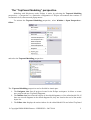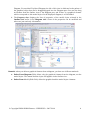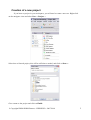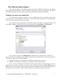
1
SME User Manual
V0.20.0 (September 2nd, 2010)
This document is a user manual for the Polychrony/SME editors inside the Eclipse
environment. It explains how to use the Polychrony/SME Plug-in suite in order to produce SME
graphical models, verify them, and generate codes for simulations. These plug-ins are still under
development, so this document will be of course updated, but the already written parts can be
modified.
SME stands for Signal Meta-model under Eclipse. The SME environment is composed of
several plug-ins which correspond to:
●
the reflexive editor,
●
the graphical modeler,
●
the reflexive editor and an Eclipse view to create compilation scenarios,
●
the Signal text editor,
●
the connection to the Polychrony services
●
some examples of Polychrony models,
●
the help of the other plug-ins.
Each of these plug-ins will be detailed in the following document. Currently, these plug-ins
work with TopCased 4.0.0 and Eclipse 3.6.0 (Helios)
For information about the TopCased project, consult its web site: http://www.topcased.org/
© Copyright IRISA/INRIA Rennes – ESPRESSO – 2007-2010
1
The Polychrony Tool set
The Polychrony toolset, based on Signal, is a development environment for critical systems,
from abstract specification until deployment on distributed systems. It relies on the application of
formal methods, allowed by the representation of a system, at the different steps of its development,
in the Signal polychronous semantic model. It provides a formal framework:
●
to validate a design at different levels,
●
to refine descriptions in a top-down approach,
●
to abstract properties needed for black-box composition,
●
to assemble predefined components (bottom-up with COTS).
Signal is based on synchronized data-flow (flows + synchronization): a process is a set of
equations on elementary flows describing both data and control, the variables of the system are
signals. A signal is a sequence of values which has a clock associated with; this clock specifies the
instants at which the values are available.
The Signal formal model provides the capability to describe systems with several clocks
(polychronous systems) as relational specifications. Relations are useful as partial specifications and
as specifications of non-deterministic devices (for instance a non-deterministic bus) or external
processes (for instance an unsafe car driver).
Using Signal allows to specify an application, to design an architecture, to refine detailed
components down to RTOS or hardware description. The Signal model supports a design
methodology which goes from specification to implementation, from abstraction to concretization,
from synchrony to asynchrony.
The principal application areas for the Signal language are that of embedded, real-time,
critical systems. Typical domains include:
●
Process control,
●
Signal processing systems,
●
Avionics,
●
Automotive control,
●
Vehicle control systems,
●
Nuclear power control systems,
●
Defense systems,
●
Radar systems...
It constitutes a development environment for critical systems, from abstract specification
until deployment on distributed systems. It relies on the application of formal methods, allowed by
the representation of a system, at the different steps of its development, in the Signal polychronous
semantic model.
For more information concerning the INRIA Polychrony environment, consult the
ESPRESSO team website: http://www.irisa.fr/espresso/Polychrony
© Copyright IRISA/INRIA Rennes – ESPRESSO – 2007-2010
2
The “TopCased Modeling” perspective
Modeling with Polychrony under Eclipse is easier by selecting the Topcased Modeling
perspective : a perspective is a particular configuration of Eclipse environment that consists of
customized views, shortcuts and popup menus.
To activate the Topcased Modeling perspective, select Window-> Open Perspective->
Other...
and select the Topcased Modeling perspective :
The Topcased Modeling perspective can be divided in 4 main part:
1. The Navigator view lists all projects located in the Eclipse workspace. It allows to create
new projects and new TopCased Diagrams.
2. The Outline view lists all model objects of the edited diagrams or of the edited model file. If
there are several diagrams in the edited diagram file, they are listed at the end of the model
object list.
3. The Editor view displays the main window for the edited Model File and edited TopCased
© Copyright IRISA/INRIA Rennes – ESPRESSO – 2007-2010
3
Diagram. For an edited TopCased Diagram, the left of this view is dedicated to the palette of
the graphical object that can be dragged/dropped into the Diagram part. One can also drag
an element from the Outline view to the Diagram part, and if there is a graphical element
which corresponds to this model object for the displayed diagram, it will be added.
4. The Property view displays the lists of properties of the model object selected in the
Outline view and/or in the Diagram view. Some of the properties can be modified and
others are just read-only information.
Remark: when you delete a graphical element from a diagram, you have two different methods:
●
Delete From Diagram (Del): delete only the graphical element from the diagram, not the
model object. This means that the object still appears in the Outline view.
●
Delete From Model (Shift+Del): delete the graphical and the model object elements.
© Copyright IRISA/INRIA Rennes – ESPRESSO – 2007-2010
4
Creation of a new project
If you have no project in your workspace, you will need to create a new one. Right-click
on the navigator view and select New -> Project ...
Select then a General project, this will be sufficient to model, and click on Next > :
Give a name to the project and click on Finish
© Copyright IRISA/INRIA Rennes – ESPRESSO – 2007-2010
5
Thus, you will obtain a new project, which contains only a .project file.
© Copyright IRISA/INRIA Rennes – ESPRESSO – 2007-2010
6
The reflexive editor plug-in
The reflexive editor is the plug-in generated from the SME meta-model by the Eclipse
Modeling Framework (EMF). It allows to specify a Polychrony model by creating the equivalence
of an Abstract Syntax Tree where the syntax is given by the meta-model meta-classes.
Creation of a new .sme model file
To help the user during the creation of a new SME model file, the reflexive editor has a
wizard. The role of the wizard is to make more convivial the task of creation by accompanying the
user. The creation will proceed in a few stages.
To start the wizard, right-click on the project where you want to create your model, and
select New-> Other... and then select the following model file : Polychrony-> SME Model.
Once you have selected the SME Model, the SME wizard is opened. Thus, you have to
choose the name of the diagram, select Next> and then select the kind of the root for the model file.
There are two kinds of root model element:
●
Model Declaration: it corresponds to a SIGNAL component (i.e. process)
●
Module: it corresponds to a library of components, types, and constants.
Once, you have chosen the root model, you have only to add new model objects. To do so,
right-click on the node on which you want to add a child, and select the New Child menu. It
displays the list of all possible model elements that can be added for the current selected element. If
this option does not exist for a node, it means that there is no possible child for this node.
© Copyright IRISA/INRIA Rennes – ESPRESSO – 2007-2010
7
Parametrization of model objects
Here, we detail how to parametrize each model objects (meta-classes that are not abstract)
that can be added in a SME model file. To be able to customize model objects, you have to display
the Property View: right on a model element and select the Show Property View action.
In the following, for each model object, we precise the children model objects that can be
added to it and each feature that can be modified by the user (not the read-only one). They are listed
in alphabetical order. For more information about the semantics of each element, consult the Signal
v4 reference manual for syntactic elements and for mode automaton elements, consult
Polychronous mode automata.
And
It corresponds to the logical And operator.
Children:
● Input Port: this operator is a multiple inputs operator, this means that you can add as
many Input Ports as Signal Expressions you need (at least 2) to connect. The ports
are ordered.
Basic
● Name: the name of the operator. It is used to identify it, so it is better if it has a
unique name.
And State
It corresponds to the synchronous composition of different substates.
Children
● The sub-states (And State, Automaton, and/or State) of the And State. It is not really
useful to add an And State to another one.
● History: connecting a transition to the history of an And State means that you enter
the previous state of all inner state of the And State.
● The shared Local signals.
Basic
● Comment: the COMMENT pragma attached to this identifier.
● Name: the name of the state. It has to be unique inside the Automaton in which the
state is contained.
Arithmetic Operator
It corresponds to any arithmetic operator present in the Signal
language.
Children:
● Input Port: this operator is a multiple inputs operator, this means that you can add as
many Input Ports as Signal Expressions you need (at least 2) to connect. The ports
are ordered.
Basic
● Name: the name of the operator. It is used to identify it, so it is better if it has a
unique name.
● Operator: this attribute is of enumerated type whose values are Addition,
Substraction, Multiplication, Division, Modulo, and Power. By default, the value of
this attribute is Addition.
© Copyright IRISA/INRIA Rennes – ESPRESSO – 2007-2010
8
Array Enumeration
It corresponds to the Signal operator for defining an array by the
ordered list of its elements.
Children:
● Input Port: this operator is a multiple inputs operator, this means that you can add as
many Input Ports as Signal Expressions you need (at least 2) to connect. The ports
are ordered.
Basic
● Name: the name of the operator. It is used to identify it, so it is better if it has a
unique name.
Array Product
It corresponds to the Signal operator for a matrix product. The
operands must have a basic type which is a numeric type.
Children:
● Input Port: this operator is a multiple inputs operator, this means that you can add as
many Input Ports as Signal Expressions you need (at least 2) to connect. The ports
are ordered.
Basic
● Name: the name of the operator. It is used to identify it, so it is better if it has a
unique name.
Array Recovery
It corresponds to the Signal operator for defining a recovery
default value when accessing to an array out of its bounds.
Children:
● Two Input Ports already created. The first one takes an array expression and the
second one takes a recovery expression, which is used when the array expression try
to access out of the bounds of the array.
Basic
● Name: the name of the operator. It is used to identify it, so it is better if it has a
unique name.
Array Restructuration
It allows to define partially an array, by defining some indicesdefined coordinate points of this array. Non defined values are
any values of correct type.
Children:
● Two Input Ports already created. The first one takes an expression corresponding to
the index(es) of the array at which the expression indicated by the second port is set.
Basic
● Name: the name of the operator. It is used to identify it, so it is better if it has a
unique name.
Assertion
It corresponds to a process with no output which specifies that a
Boolean expression must have the value true each time it is
present.
Children: none
© Copyright IRISA/INRIA Rennes – ESPRESSO – 2007-2010
9
Basic
●
●
Expression: the boolean expression to check in a textual form. If a Condition
references this Assertion, the boolean expression at the source of this Condition will
be the expression to check.
Name: the name of the operator. It is used to identify it, so it is better if it has a
unique name.
Assertion Clock
Constraint Operator
It corresponds to the different kind of clock constraint operator in
a context of an assertion. To use this operator, connect the
different expressions to it with Clock Relation model object.
Children: none
Basic
● Name: the name of the operator. It is used to identify it, so it is better if it has a
unique name.
● Operator: this attribute is of enumerated type whose values are Synchronized (clocks
are equal), Excluded (specifies the mutual exclusion of the expression clocks), and
Identity (specifies the equality of values and clocks of the expressions). By default, the
value of this attribute is Synchronized.
Assertion Clock Speed
Operator
It corresponds to a clock constraint operator which constraints
the speed of a Clocked Expression to be greater (or smaller) than
the speed of another Clock Expression. This means that the first
Clocked Expression is more (or less) frequently present that the
second one. This operator is used in the context of an assertion.
Children:
● Input Port: this operator is a multiple inputs operator, this means that you can add as
many Input Ports as Signal Expressions you need (at least 2) to connect. The ports
are ordered.
Basic
● Name: the name of the operator. It is used to identify it, so it is better if it has a
unique name.
● Operator: this attribute is of enumerated type whose values are Smaller, and Greater.
By default, the value of this attribute is Smaller.
Automaton
It corresponds to the definition of a mode automaton.
Children:
● The sub states (And State, Automaton, and/or State) indicates the different execution
mode in which the Automaton can be. At each instant, the Automaton can execute at
most one mode.
● History: connecting a transition to the history of an Automaton means that you reexecute the last mode of this Automaton.
● The shared Local signals.
● The transitions (Weak Transitions, or Strong Transitions) of the Automaton define
the means to go from one state to another one when their guard is true.
Basic
© Copyright IRISA/INRIA Rennes – ESPRESSO – 2007-2010
10
●
●
●
Comment: the COMMENT pragma attached to this identifier.
The Initial State indicates the initial state of this automaton. All possible states are
listed in the combo box.
Name: the name of the Automaton which is used as its identifier. It has to be unique
inside its container. It is even better to name it uniquely inside the file.
Basic Iterate
It corresponds to a C- for loop: for(i=0; i <= N; i++). It is a
particular case of the Iterate block.
Children
● Iteration Init: this model object already created is used to specify, if any, how to
initialize the iteration. When you try to delete this object, it is automatically rebuilt,
but it will be empty.
● Iterator: it is a constant expression that is used to iterate among all elements
contained in the Basic Iterate block. It corresponds to the i parameter in a C- for loop
for(i=0; i <= N; i++). The iterator is automatically added to the Basic Iterate block.
When you try to delete this object, it is automatically rebuilt with unset attribute.
● Any of the children that can be in a process: it means all model objects except the
following list: And State, Input, Model Declaration, Output, Parameter, Pragma,
State, Strong Transition, and Weak Transition.
Basic
● Comment: the COMMENT pragma attached to this identifier.
● Iterator Name is used to get/set the name of the iterator used by the Basic Iterate
Block. This attribute is a shortcut. Obviously, one can change the name of the iterator
directly in the Iterator element.
● Name: the name of the Iterate which is used as its identifier. It has to be unique inside
its container. It is even better to name it uniquely inside the file.
● Upper Bound represents the upper bounds of the iteration (the N parameter of the Cfor loop). It has to be an integer expression: integer value, expression using signals...
Boolean Expression
It corresponds to a complete boolean expression. It was added to
the meta-model to avoid a long description of a complete
boolean expression.
Children: none
Basic
● Expression: the boolean expression in a textual form.
● Name: the name of the operator. It is used to identify it, so it is better if it has a
unique name.
Cartesian Product
The Cartesian product is used mainly to define jointly indexes, to
be used in Iterate model object. Intuitively, the sequence of
iteration is represented by the first dimension of the indexes
(which are vectors).
Children:
● Input Port: this operator is a multiple inputs operator, this means that you can add as
many Input Ports as you need (at least 2). The ports are ordered.
● Output Port: this operator has also as many Output Ports as Input Ports (at least 2)
© Copyright IRISA/INRIA Rennes – ESPRESSO – 2007-2010
11
and they are ordered too.
Basic
●
Name: the name of the operator. It is used to identify it, so it is better if it has a
unique name.
Case Connection
●
It corresponds to a case for the switch operator.
Children: none
Basic
● Case Kind: this attribute is of enumerated type whose values are ElseCase,
Enumeration, ClosedInterval, LeftHalfOpenInterval, RightHalfOpenInterval, and
OpenInterval. By default, the value of this attribute is ElseCase.
● Enumeration: if the enumeration case kind is selected, this attribute is used to
enumerate the values for the current case.
● Lower Bound is used to specify the lower bound of an interval. If the Case Kind is
one of the interval kind, and if no value is specified for the lower bound, the value is
-∞ . Intervals are not fully implemented by the compiler yet.
● Name: the name of the model object. It is used to identify it, so it is better if it has a
unique name.
● Upper Bound is used to specify the upper bound of an interval. If the Case Kind is
one of the interval kind, and if no value is specified for the lower bound, the value is
+∞ . Intervals are not fully implemented by the compiler yet.
Source-Target
● Dst: any of the Sub Process or Iterate model object, which is at the same hierarchical
level.
● Src: any of the Switch operator, which is at the same hierarchical level.
Cell
It corresponds to the memorization operator which allows to
memorize a given signal when the signal is present and the
boolean expression is true.
Children
● One Input Port already created which has to be connected to the expression to
memorize. The boolean expression has to be specified through the use of a Condition
whose target is the Cell operator.
Basic
● The Initial Value is the value used to initialize the memory.
● Name: the name of the operator. It is used to identify it, so it is better if it has a
unique name.
Clock Constraint Operator It corresponds to the different kind of clock constraint operator.
To use this operator, connect the different expressions to it with
Clock Relation model object.
Children: none
Basic
● Name: the name of the operator. It is used to identify it, so it is better if it has a
© Copyright IRISA/INRIA Rennes – ESPRESSO – 2007-2010
12
●
unique name.
Operator: this attribute is of enumerated type whose values are Synchronized (clocks
are equal), Excluded (specifies the mutual exclusion of the expression clocks), and
Identity (specifies the equality of values and clocks of the expressions). By default, the
value of this attribute is Synchronized.
Clock Relation
It corresponds to a clock relation between two clocked
expressions. A Clocked Expression is either a signal (Input,
Output, Local, Signal Ref, Input Instance, Output Instance), or a
Sub Process, or an Iterate, or a Model Instance, or an Automaton,
or any clock operator (Clock Constraint Operator, Clock
Relation Operator, Clock Speed Operator).
Basic
Name: the name of the model object. It is used to identify it, so it is better if it has a
unique name.
Source-Target
● Dst: the target of a Clock Relation is a Clocked Expression.
● Dst Field: if the target is a Signal using a Tuple Type or an array type, this attribute is
the way to access to the signal field.
● Src: the source of a Clock Relation is also a Clocked Expression.
● Src Field: if the source is a Signal using a Tuple Type or an array type, this attribute
is the way to access to the signal field.
●
Clock Relation Operator
It corresponds to the set operators for clocked expressions.
Children:
● Input Port: this operator is a multiple inputs operator, this means that you can add as
many Input Ports as Signal Expressions you need (at least 2) to connect. The ports
are ordered.
Basic
● Name: the name of the operator. It is used to identify it, so it is better if it has a
unique name.
● Operator: this attribute is of enumerated type whose values are Union, Intersection,
and Complementary. By default, the value of this attribute is Union.
Clock Speed Operator
It corresponds to a clock constraint operator which constraints
the speed of a Clocked Expression to be greater (or smaller) than
the speed of another Clock Expression. This means that the first
Clocked Expression is more (or less) frequently present that the
second one.
Children:
● Input Port: this operator is a multiple inputs operator, this means that you can add as
many Input Ports as Signal Expressions you need (at least 2) to connect. The ports
are ordered.
Basic
● Name: the name of the operator. It is used to identify it, so it is better if it has a
© Copyright IRISA/INRIA Rennes – ESPRESSO – 2007-2010
13
●
unique name.
Operator: this attribute is of enumerated type whose values are Smaller, and Greater.
By default, the value of this attribute is Smaller.
Comparison Operator
It corresponds to the Boolean relations of equality, difference,
and strict and non strict greater and lower relations. The value of
both expression must be comparable.
Children
● Two Input Ports already created, which corresponds to the operands of the selected
comparison operator.
Basic
● Name: the name of the operator. It is used to identify it, so it is better if it has a
unique name.
● Operator: this attribute is of enumerated type whose values are Equal, Not Equal,
Greater, Greater Or Equal, Smaller, Smaller Or Equal, Equal Any, and Smaller Or
Equal Any. By default, the value of this attribute is Equal. The difference between
Equal and Equal Any, is that if the first one is applied on two vectors, the result is a
vector of Booleans, where as the second one returns a single Boolean value (same
distinction between Smaller Or Equal and Smaller Or Equal Any).
Complex Operator
It corresponds to the operator for building complex number.
Children
● Two Input Ports already created. The first one represents the real part of the complex
number and the second the imaginary part.
Basic
● Name: The name of the operator. It is used to identify it, so it is better if it has a
unique name.
Concatenation
It corresponds to the concatenation operation, which allows to
concatenate arrays along to their first dimension.
Children:
● Input Port: this operator is a multiple inputs operator, this means that you can add as
many Input Ports as Signal Expressions you need (at least 2) to connect. The ports
are ordered. On each Input Port, an array expression has to be connected.
Basic
● Name: the name of the operator. It is used to identify it, so it is better if it has a
unique name.
Condition
It corresponds to the expression of a condition for some specific
Conditioned Expression: the Assertion, the Cell, the Dependence
Operator, the Extraction, or the If Then Else.
Children: none
Basic
● Condition Kind: this attribute is of enumerated type whose values are Present, True,
© Copyright IRISA/INRIA Rennes – ESPRESSO – 2007-2010
14
●
and False. By default, the value of this attribute is Present. Present check the
presence of a signal; True and False check the value of a Boolean Expression or a
Boolean signal.
● Name: the name of the model object. It is used to identify it, so it is better if it has a
unique name.
Source-Target
● Dst: the target of a Condition is a Conditioned Expression.
● Src: the source of a Condition is a Boolean Expression or a Signal. It can also be a
Merge, an Array Recovery, a Cell, a Delay, an Extraction, or an If Then Else
operator, but be sure, that the expression returns a boolean result.
● Src Field: if the source is a Signal using a Tuple Type or an array type, this attribute
is the way to access to the signal field.
Constant Affectation
●
●
It corresponds to the initialization of a Constant Value or a
Parameter Instance by a constant expression. For the Constant
Value, you can also use the Value attribute.
Children: none
Basic
● Name: the name of the model object. It is used to identify it, so it is better if it has a
unique name.
Expert
● Array Recovery Expression defines the value of the expression for the values of
index outside the segment (used only for array expression).
Source-Target
● Dst: the target of a Constant Affectation is a Constant Value or a Parameter Instance.
● Src: the source is a Constant Expression, this means that it is an expression built only
with constant value.
● Src Field: if the source is a Signal using a Tuple Type or an array type, this attribute
is the way to access to the signal field.
Constant Ref
It corresponds to the use of a Constant Value or a Parameter at
another hierarchical level than these where the Constant Value or
Parameter is declared.
Children: none
Basic
● Constant: points to the referring Constant Value or the Parameter.
Constant Value
It corresponds to the declaration of a constant.
Children: none
Basic
● Array Dimensions indicates the dimensions of the Constant Value, if it is an array. If
it is a multi-dimensional array, specify one dimension per line. A dimension is a
constant expression: Constant Value, Parameter, an integer positive number...
● Comment: the COMMENT pragma attached to this identifier.
● Name: the name of the Constant Value which is used as its identifier. It has to be
© Copyright IRISA/INRIA Rennes – ESPRESSO – 2007-2010
15
●
●
●
unique inside its container. It is even better to name it uniquely inside the file.
Type: it corresponds to one of the Intrinsic Primitive Type or to one of the type
declared. To access to a type declared in the file, the Constant Value has to be in the
scope of this declaration.
Value: indicates the value of the constant. If the constant is an array, specify one
value (of the first dimension) per line.
Visibility: indicates the visibility (public or private) if the Constant Value is declared
inside a Module. If it is declared in a Model Declaration, this information is useless.
Counter
It allows the numbering of the occurrences of a signal.
Children:
● Two Input Ports already created. The first one has to be connected to the Signal
Expression, which has to be numbered, and the second to a reseting event (if Counter
Kind is After or From) or to a constant integer expression (if Counter Kind is Count).
Basic
● Counter Kind: this attribute is of enumerated type whose values are After, From, and
Count. By default, the value of this attribute is After. After means that it counts the
number of occurrences of the first Signal Expression since the last occurrence of the
reseting event. From works as After, but if the Signal Expression and the reseting
event are simultaneous, it is counted by From (not by After). Count means that it
counts the number of occurrences of the Signal Expression modulo the number of the
second expression.
● Name: the name of the operator. It is used to identify it, so it is better if it has a
unique name.
Dataflow Connection
●
●
It corresponds to the Signal definition (or partial definition). It
constitutes the main link between signal expressions.
Children: none
Basic
● Name: the name of the model object. It is used to identify it, so it is better if it has a
unique name.
Expert
● Cast Type: it corresponds to the casting type for the source expression. The type is
one of the Intrinsic Primitive Type.
● Is Default Value: if the destination is a shared Local signal or a state variable, this
attribute indicates if the source expression constitutes the default value of the partial
definition.
● Use Last Iteration Value: indicates if the source expression used is those computed
during the last iteration (this attribute is only used inside an Iterate model).
● Use Src Clock: indicates if the Dataflow Connection uses the clock of the source or
its value.
Source-Target
● Dst: the target of a Dataflow Connection is a Signal (Input Instance, Local, Output,
Signal Ref) or an Input Port of an operator (except for Clock Relation Operator).
● Dst Field: if the target is a Signal using a Tuple Type or an array type, this attribute is
the way to access to the signal field.
© Copyright IRISA/INRIA Rennes – ESPRESSO – 2007-2010
16
●
●
Src: the source of a Dataflow Connection is a Signal Expression: operators (except
Clock Constraint Operator, Clock Relation Operator, Clock Speed Operator, and
Dependence Operator), Signals, or Output Port.
Src Field: if the source is a Signal using a Tuple Type or an array type, this attribute
is the way to access to the signal field.
Delay
It corresponds to the delay operator which returns the Nb
Instants-th previous value of a Signal Expression, except for its
first Nb Instants-th execution where it uses the initial value.
Children:
● One Input Port already created to connected the Signal Expression to delay.
Basic
● Initial Value initialize the value for the Nb Instants-th first execution of the operators.
This means that, if Nb Instants is greater than 1, the initial value has to be an array
whose size is Nb Instants.
● Name: the name of the operator. It is used to identify it, so it is better if it has a
unique name.
● Nb Instants: the size of the delay. You can specify an integer positive value or the
name of a constant value.
Dependence
●
It corresponds to an explicit specification of dependences
between Identifiers (Signals, Model Instance, Sub Process, or
Iterate) model objects. When the source (or target) is a Model
Instance, a Sub Process, or an Iterate model object, it means that
all Signals defined in these structure enter in the Dependence
relation.
Children: none
Basic
● Name: the name of the model object. It is used to identify it, so it is better if it has a
unique name.
Source-Target
● Dst: the target of a Dependence is an Identifier model object.
● Dst Field: if the source is a Signal using a Tuple Type or an array type, this attribute
is the way to access to the signal field.
● Src: the source of a Dependence is an Identifier model object.
● Src Field: if the source is a Signal using a Tuple Type or an array type, this attribute
is the way to access to the signal field.
Dependence Operator
It has been introduced to represent conditional Dependences.
Thus, one can connect the target of a Condition to this operator,
and the source or target of several Dependences.
Children: none
Basic
● Name: the name of the operator. It is used to identify it, so it is better if it has a
unique name.
© Copyright IRISA/INRIA Rennes – ESPRESSO – 2007-2010
17
Enumeration Type
It corresponds to the type declaration of an enumeration. To
access to the value of an enumerated type, prefix the value by a
'#'.
Children: none
Basic
● Array Dimensions indicates the dimensions of the Enumeration Type, if it is an array
type. If it is a multi-dimensional array, specify one dimension per line. A dimension
is a constant expression: Constant Value, Parameter, an integer positive number...
● Comment: the COMMENT pragma attached to this identifier.
● Enum Values indicates the values of the enumeration. Put one value per line.
● Name: the name of the Enumeration Type, which is used as its identifier. It has to be
unique inside its container. It is even better to name it uniquely inside the file.
● Visibility indicates the visibility (public or private) if the Enumeration is declared
inside a Module. If it is declared in a Model Declaration, this information is useless.
Enumeration Value
It corresponds to an unnamed constant value whose type is an
enumerated type
Children: none
Basic
● Type Value indicates the name of the enumerated type if any. A list of enumerated
type containing in the scope is proposed.
● Value indicates the value used inside the enumerated type. No need to prefix the
value with a '#' character.
Extraction
It corresponds to the extraction operator. A value is returned
each time the Condition is true and there is a value on the Input
Port.
Children
● One Input Port already created to connected the Signal Expression whose value has
to be extracted each time the Condition is true.
Basic
● Name: the name of the operator. It is used to identify it, so it is better if it has a
unique name.
History
It corresponds to the History state of an Automaton or of an And
State. When a transition leads to such a state, it means that the
container state is not reinitialized and re-executes its last state.
Children: none
If Then Else
It corresponds to the synchronous condition. It is an expression
on signals of same clock.
Children:
● Two Input Ports already created. The first one has to be connected to the then Signal
Expression, and the second to the else Signal Expression. Both expressions have to
be of the same type.
© Copyright IRISA/INRIA Rennes – ESPRESSO – 2007-2010
18
Basic
●
Name: the name of the operator. It is used to identify it, so it is better if it has a
unique name.
Index
It corresponds to the definition of an index. An index is a vector
of integers whose size is equal to (To – From) / Step. It is used
by Iterate model object.
Children: none
Basic
● Comment: the COMMENT pragma attached to this identifier.
● From: a Signal Expression which constitutes the starting value of the Index.
● Name: the name of the Index which is used as its identifier. It has to be unique inside
its container. It is even better to name it uniquely inside the file.
● Step: an integer Constant Expression different from 0. If the value is omitted, it is
equal to 1.
● To: a Signal Expression which constitutes the ending limit of the Index.
Input
It corresponds to the declaration of an input signal in a Model
Declaration. Because it represents an input of the declaration of a
Model, it cannot be the target of a Dataflow Connection (only an
Instance of the Input can be the target of a Dataflow
Connection).
Children: none
Basic
● Array Dimensions indicates the dimensions of the Input, if it is an array. If it is a
multi-dimensional array, specify one dimension per line. A dimension is a constant
expression: Constant Value, Parameter, an integer positive number...
● Comment: the COMMENT pragma attached to this identifier.
● Initial Value initialize the value of the Input.
● Name: the name of the Input which is used as its identifier. It has to be unique inside
its container. It is even better to name it uniquely inside the file.
● Type: it corresponds to one of the Intrinsic Primitive Type or to one of the type
declared. To access to a type declared in the file, the Input has to be in the scope of
this declaration.
Input Instance
It corresponds to the instance of an Input. Inside a Model
Instance, it refers to one of the Input declared in the instantiated
Model Declaration. To obtain Input Instance model object, refer
to the Model Instance description.
Children: none
Basic
● Comment: the COMMENT pragma attached to this identifier.
● Name: the name of the Input Instance which is used as its identifier. It has to be
unique inside its container. It is even better to name it uniquely inside the file.
© Copyright IRISA/INRIA Rennes – ESPRESSO – 2007-2010
19
Input Port
It corresponds to a port of a Signal Operator. By default, such
port is not typed, but according to the operator containing the
port, it is typed. Each Input Port has to be connected.
Children: none
Iterate
It corresponds to an iteration of processes. It is mainly used to
apply the same behavior on arrays.
Children
● Input Port: this operator is as a multiple inputs operator, this means that you can add
as many Input Ports as Indexes or integer array you need to connect. The ports are
ordered.
● Iteration Init: this model object already created is used to specify, if any, how to
initialize the iteration. When you try to delete this object, it is automatically rebuilt,
but it will be empty.
● Any of the children that can be in a process: it means all model objects except the
following list: And State, Input, Model Declaration, Output, Parameter, Pragma,
State, Strong Transition, and Weak Transition.
Basic
● Comment: the COMMENT pragma attached to this identifier.
● Name: the name of the Iterate which is used as its identifier. It has to be unique inside
its container. It is even better to name it uniquely inside the file.
Iteration Init
It corresponds to the area in which the initialization of an
iteration of processes have to be made.
Children
● Any of the children that can be in a process: it means all model objects except the
following list: And State, Input, Model Declaration, Output, Parameter, Pragma,
State, Strong Transition, and Weak Transition.
Iterator
It corresponds to the iterator index of a C-for loop. It has to be
used to refer the current number of loop of the Basic Iterate
block. An Iterator can be referenced by a Constant Ref element.
Children: none
Basic
● Comment: the COMMENT pragma attached to this identifier.
● Name: the name of the Iterator index, which is used as its identifier. It has to be
unique inside its container. It is even better to name it uniquely inside the file.
Literal
It corresponds to an unnamed constant value.
Children: none
Basic
● Value indicates the value of the literal. The literal can be either a boolean, or an
integer, or a real, or a string, or a character value. If the literal is a string, do not
© Copyright IRISA/INRIA Rennes – ESPRESSO – 2007-2010
20
forget to use double quote. If the literal is a character, use simple quote.
Local
It corresponds to the declaration of a local signal. This signal can
be used at its declaration level and in all sub-levels.
Children: none
Basic
● Array Dimensions indicates the dimensions of the Local signal, if it is an array. If it
is a multi-dimensional array, specify one dimension per line. A dimension is a
constant expression: Constant Value, Parameter, an integer positive number...
● Comment: the COMMENT pragma attached to this identifier.
● Initial Value initialize the value of the Local signal.
● Name: the name of the Local signal which is used as its identifier. It has to be unique
inside its container. It is even better to name it uniquely inside the file.
● Type: it corresponds to one of the Intrinsic Primitive Type or to one of the type
declared. To access to a type declared in the file, the Local signal has to be in the
scope of this declaration.
● Status indicates if the signal is a normal signal, a shared signal, or a state variable. A
state variable is a typed sequence the elements of which are present as frequently as
necessary. It keeps its previous value as long as a new one is defined. A shared signal
is a signal whose value is partially defined at different place.
Merge
It corresponds to the operator that merge different flows of data.
The flows are ordered according to the order of the Input Port to
which they are connected. If they is a value on the first flow, it
will be taken, else we check the second, and so on among the
different flows.
Children:
● Input Port: this operator is a multiple inputs operator, this means that you can add as
many Input Ports as Signal Expressions you need (at least 2) to connect. The ports
are ordered.
Basic
● Name: the name of the operator. It is used to identify it, so it is better if it has a
unique name.
Model Declaration
It corresponds to the declaration of a SIGNAL component with
its Input/Output Signals and its input constant Parameter. It is
only a declaration of a component. It has to be instantiated
(Model Instance) to be used and connected to the rest of a
system. It constitutes one of the Root Model, but it can also be
declared locally in another Model Declaration or in a Module.
Children
● Input, Output, and Parameter are added to specify the interface of this component.
● Specifications (already added) is used to specify the clock relations and the
dependences between input and output signals.
● Any of the children that can be in a process: it means all model objects except those
concerning the mode automaton: And State, State, Strong Transition, and Weak
© Copyright IRISA/INRIA Rennes – ESPRESSO – 2007-2010
21
Transition.
Basic
●
●
●
Comment: the COMMENT pragma attached to this identifier.
Name: the name of the Model Declaration which is used as its identifier. It has to be
unique inside its container. It is even better to name it uniquely inside the file.
Visibility indicates the visibility (public or private) if the Model Declaration is
declared inside a Module. If it is declared in a Model Declaration, this information is
useless.
Expert
Model Type: this attribute is of enumerated type whose values are action, function,
node, and process. By default, the value of this attribute is process. For more
information, consult the Signal v4 reference manual.
● Process Class: this attribute is of enumerated type whose values are safe,
deterministic, and unsafe. By default, the value of this attribute is unsafe. For more
information, consult the Signal v4 reference manual.
● Type indicates the Model Type of the Model Declaration if it is typed. Typing a
Model Declaration by a Model Type is the means to reuse the same interface (Input/
Output Signals and constant Parameters) for several Model Declarations. Thus, you
have not to specify the interface of your Model Declaration, it is automatically
specified by the Model Type.
External Code
● CCode: It is specific to code generation. It is a “parameterized” string representing a
piece of C code. Each call of the model is translated by this string in the generated
code, after substitution of the encoded parameters by the corresponding signals in the
considered call. The following encoded parameters may be used in the string:
○ &pj (where j is a constant integer value) represents the jth parameter of the call;
○ &ij (where j is a constant integer value) represents the jth input signal of the call;
○ &oj (where j is a constant integer value) represents the jth output signal of the
call;
○ &t&xj (where x is either p, i or o, and j is a constant integer value) represents the
type of the jth parameter, or input signal, or output signal of the call;
○ &n represents the name of the model.
● Cpp Code: The same as CCode, but for the C++ generation.
● Java Code: The same as CCode, but for the Java generation.
Pragmas
● Compilation Directive: this attribute is of enumerated type whose values are NONE,
unexpanded, separate, Black Box, Grey Box, and Delay Cluster. By default, the value
of this attribute is NONE. For more information, consult the list of Polychrony
pragmas in Signal v4 reference manual.
● Is Main indicates if the Model Declaration is an entry point of a Module (used only
when the Model Declaration is a child of a Module).
● Is Sigali Process indicates if the current Model Declaration is a specific process for
the Sigali model-checker tool.
● Processor Type: string representing a name, for example, "DSP", that should be the
name of a file DSP.LIB containing a module that defines the cost of each operator by
particular models. When profiling (performance evaluation) is required on a given
program implemented on some processor represented as a model with this attribute
set, a morphism of this program is applied, that defines a new program representing
●
© Copyright IRISA/INRIA Rennes – ESPRESSO – 2007-2010
22
●
cost evaluation of the original program. The image of the original program by this
morphism uses the library designated by the pragma to interpret the cost evaluation
operators.
Run On: a constant integer value i. When a partitioning based on the use of this
pragma is applied on an application, the application is partitioned according to the n
different values of the pragma so as to obtain n sub-models. The tree of clocks and
the interface of these sub-models may be completed in such a way that they represent
endochronous processes.
Model Instance
It corresponds to the instantiation of a SIGNAL component. To
use it, specify the Referred Interface attribute, right-click on the
Model Instance Node and select « Load Model Instance
Inputs/Outputs » action. This action creates the Input Instances,
Output Instances, and Parameters Instances corresponding to
those of the Referred Interface.
Children
● Input, Output, and Parameter Instances are automatically added when the Referred
Interface is set and the « Load Model Instance Inputs/Outputs » action is called.
Basic
● Comment: the COMMENT pragma attached to this identifier.
● Name: the name of the Model Instance which is used as its identifier. It has to be
unique inside its container. It is even better to name it uniquely inside the file.
Instantiation
● Referred Interface: refers to a Model Declaration or a Model Type to instantiate.
● Referred Parameter: for generic purpose, a Model Declaration can be passed as
parameters. Thus, the Referred Interface has to be set with a Model Type, and the
Referred Parameter will indicate the instantiated Model Declaration.
Model Ref
It allows to refer to a Model Declaration declared at the upper
hierarchic level (only useful to connect a Model Declaration to a
Parameter Instance).
Children: none
Basic
● Model: points to the referring Model Declaration.
Model Type
It corresponds to the declaration of a specific type allowing to
type a Model Declaration. As for a Model Declaration, an
interface (Input, Output, Parameter, and a Specification area) has
to be specified.
Children
● Input, Output, and Parameter are added to specify the interface of this component.
● Specifications (already added) is used to specify the clock relations and the
dependences between input and output signals.
Basic
● Comment: the COMMENT pragma attached to this identifier.
● Name: the name of the Model Type which is used as its identifier. It has to be unique
© Copyright IRISA/INRIA Rennes – ESPRESSO – 2007-2010
23
●
inside its container. It is even better to name it uniquely inside the file.
Visibility indicates the visibility (public or private) if the Model Type is declared
inside a Module. If it is declared in a Model Declaration, this information is useless.
Expert
●
●
●
Model Type: this attribute is of enumerated type whose values are action, function,
node, and process. By default, the value of this attribute is process. For more
information, consult the Signal v4 reference manual.
Process Class: this attribute is of enumerated type whose values are safe,
deterministic, and unsafe. By default, the value of this attribute is unsafe. For more
information, consult the Signal v4 reference manual.
Type indicates the Model Type referenced by the current one.
Module
It corresponds to a library of types, components, and constant
values.
Children
● Model Declarations: one can declared different Model Declarations. Some of them
can be private (only usable by the other Model Declarations of the Module) or public
(that can be imported by external Model Declarations that specify this Module in the
Use Module model object). If one (or several) of the Model Declarations has its Is
Main set to true, it becomes an entry execution point for this Module.
● Type (Enumeration, Model Type, Substitution Type, or Tuple Type) can also be
declared public or private.
● Constant Values can also be declared public or private.
● Use Module: indicates the list of other Modules needed by this one.
Basic
● Comment: the COMMENT pragma attached to this identifier.
● Name: the name of the Module which is used as its identifier. It has to be unique
inside its container. It is even better to name it uniquely inside the file.
Not
It corresponds to the logical Not operator.
Children
● One Input Port (already created): used to connect a Boolean Expression.
Basic
● Name: the name of the operator. It is used to identify it, so it is better if it has a
unique name.
Null Clock
It corresponds to the empty clock, which corresponds to the
clock without any instant, to an event that never occurs.
Children: none
Numeric Expression
It corresponds to a complete numeric expression. It was added to
the meta-model to avoid a long description of a complete
arithmetic expression.
Children: none
© Copyright IRISA/INRIA Rennes – ESPRESSO – 2007-2010
24
Basic
●
●
Expression: the arithmetic expression in textual form.
Name: the name of the operator. It is used to identify it, so it is better if it has a
unique name.
Or
It corresponds to the logical Or operator.
Children:
● Input Port: this operator is a multiple inputs operator, this means that you can add as
many Input Ports as Signal Expressions you need (at least 2) to connect. The ports
are ordered.
Basic
● Name: the name of the operator. It is used to identify it, so it is better if it has a
unique name.
Output
It corresponds to the declaration of an output signal in a Model
Declaration.
Children: none
Basic
● Array Dimensions indicates the dimensions of the Output, if it is an array. If it is a
multi-dimensional array, specify one dimension per line. A dimension is a constant
expression: Constant Value, Parameter, an integer positive number...
● Comment: the COMMENT pragma attached to this identifier.
● Initial Value initialize the value of the Output.
● Name: the name of the Output which is used as its identifier. It has to be unique
inside its container. It is even better to name it uniquely inside the file.
● Type: it corresponds to one of the Intrinsic Primitive Type or to one of the type
declared. To access to a type declared in the file, the Output has to be in the scope of
this declaration.
Output Instance
It corresponds to the instance of an Output. Inside a Model
Instance, it refers to one of the Output declared in the
instantiated Model Declaration. To obtain Output Instance
model object, refer to the Model Instance description.
Children: none
Basic
● Comment: the COMMENT pragma attached to this identifier.
● Name: the name of the Output Instance which is used as its identifier. It has to be
unique inside its container. It is even better to name it uniquely inside the file.
Output Port
It corresponds to an output port of a Cartesian Product (it is the
only Signal Operator with Output Ports). Each Output Port has
to be connected to a Signal (Input Instance, Local, Output), or to
a Signal Reference.
Children: none
© Copyright IRISA/INRIA Rennes – ESPRESSO – 2007-2010
25
Parameter
It corresponds to the declaration of a constant parameter in a
Model Declaration.
Children: none
Basic
● Array Dimensions indicates the dimensions of the Parameter, if it is an array. If it is a
multi-dimensional array, specify one dimension per line. A dimension is a constant
expression: Constant Value, Parameter, an integer positive number...
● Comment: the COMMENT pragma attached to this identifier.
● Name: the name of the Parameter which is used as its identifier. It has to be unique
inside its container. It is even better to name it uniquely inside the file.
● Type: it corresponds to one of the Intrinsic Primitive Type, to one of the type
declared, or it can be of type type. To access to a type declared in the file, the
Parameter has to be in the scope of this declaration. A Parameter is, with the Model
Declaration or the Model Type, the only mode object that can be typed with a Model
Type.
Parameter Instance
It corresponds to the instance of a Parameter. Inside a Model
Instance, it refers to one of the Parameter declared in the
instantiated Model Declaration. To obtain Parameter Instance
model object, refer to the Model Instance description.
Children: none
Basic
● Comment: the COMMENT pragma attached to this identifier.
● Name: the name of the Parameter Instance which is used as its identifier. It has to be
unique inside its container. It is even better to name it uniquely inside the file.
Pragma
It corresponds to the definition of a pragma whose role is to
associate specific informations with the objects of a Model.
These informations may be used by a compiler or another tool.
Children: none
Basic
● Expression: a string representing the information to associate with the target objects.
● Name: the name of the operator. It is used to identify it, so it is better if it has a
unique name.
● Pragma: a string which represents the kind of the pragma
● Target: a list of identifiers on which this pragma is applied.
Repetition Operator
It corresponds to the repetition operator, which is a simple form
of iterative enumeration, which allows the finite repetition of a
value. The result of this operator is an array with several times
the value connected to the first Input Port. The number of
repetitions is represented by the second Input Port
Children
● Two Input Ports already created. The first one takes an expression used to fill the
array and the second takes the number of repetitions, i.e. the size of the built array.
© Copyright IRISA/INRIA Rennes – ESPRESSO – 2007-2010
26
The expression connected to the second Input Port have to represent a strictly
positive integer value.
Basic
●
Name: the name of the operator. It is used to identify it, so it is better if it has a
unique name.
Sequential Definition
It corresponds to the sequential definition operator, which is
used mainly for the redefinition of elements of arrays. For an
example with 2 Input Ports, the result will be an array which
takes the value of the expression connected to the second Input
Port at each point at which it is defined, and the value of the
expression connected to the first Input Port elsewhere. In the
general case, both expressions value are arrays with the same
number of dimensions.
Children:
● Input Port: this operator is a multiple inputs operator, this means that you can add as
many Input Ports as Signal Expressions you need (at least 2) to connect. The ports
are ordered.
Basic
● Name: the name of the operator. It is used to identify it, so it is better if it has a
unique name.
Signal Ref
It corresponds to the use of a Signal (Input, Output, Local, Input
Instance or Output Instance) at another hierarchical level than
these where the Signal is declared.
Children: none
Basic
● Signal: points to the referring Signal.
Specifications
It corresponds to the area to specify some properties. It uses a
process expression that can make reference (through Constant
Ref, or Signal Ref) to the Parameters and Input and Output
signals of the Model. Any other identifier used in this expression
is that of a local object (signal, process model, etc.), that must
have a declaration in this expression. This aera is used in Model
Declaration and Model Type model objects for this reason. It is
also used in the Tuple Type declaration to specify some
properties between different signals, if the Tuple Type is a
bundle.
Children
● Any of the children that can be in a process: it means all model objects except the
following list: And State, Input, Iteration Init, Model Declaration, Output, Parameter,
Pragma, Specifications, State, Strong Transition, and Weak Transition.
State
It corresponds to a leaf-state of an Automaton. It contains
directly the specification of the mode.
© Copyright IRISA/INRIA Rennes – ESPRESSO – 2007-2010
27
Children
● Any of the children that can be in a process: it means all model objects except the
following list: And State, Input, Iteration Init, Model Declaration, Output, Parameter,
Pragma, Specifications, State, Strong Transition, and Weak Transition.
Basic
● Comment: the COMMENT pragma attached to this identifier.
● Name: the name of the state which is used as its identifier. It has to be unique inside
its container. It is even better to name it uniquely inside the file.
Strong Transition
●
It corresponds to a transition of an Automaton. A Strong
Transition is evaluated, for the current instant, before the
execution of its source state. If the guard is true, the mode of the
Automaton for the current instant will be the target state. In a
specific Automaton, only one Strong Transition can be taken
during an instant.
Children: none
Basic
● Guard is a textual boolean expression to express when to go from the source state to
the target state.
● Name: the name of the model object. It is used to identify it, so it is better if it has a
unique name.
● Priority is an integer value which indicates, for states with several out-going Strong
Transitions, the order of their evaluation.
Source-Target
● Dst: the target of a Strong Transition is a sub-state (And State, Automaton, or State)
of the Automaton which belongs this transition, or the History of one of them.
● Src: the source of a Strong Transition is a sub-state (And State, Automaton, or State)
of the Automaton which belongs this transition.
Sub Process
It corresponds to a sub part of a component without any specific
Input/Output signals. It can also be used to specify the different
case of the Switch operator. One can also specify some clock
constraints/relations (or dependences) with a Sub Process: this
means that all signals defined in the Sub Process will be related
to these constraints/relations.
Children
● Any of the children that can be in a process: it means all model objects except the
following list: And State, Input, Iteration Init, Model Declaration, Output, Parameter,
Pragma, Specifications, State, Strong Transition, and Weak Transition.
Basic
● Comment: the COMMENT pragma attached to this identifier.
● Name: the name of the Sub Process which is used as its identifier. It has to be unique
inside its container. It is even better to name it uniquely inside the file.
Substitution Type
It corresponds to a generic type that can refer another one.
© Copyright IRISA/INRIA Rennes – ESPRESSO – 2007-2010
28
Children: none
Basic
● Array Dimensions indicates the dimensions of the Substitution Type, if it is an array
type. If it is a multi-dimensional array type, specify one dimension per line. A
dimension is a constant expression: Constant Value, Parameter, an integer positive
number...
● Comment: the COMMENT pragma attached to this identifier.
● Is External indicates if the referenced type is defined outside the context of the Model
(for example, in a C library).
● Name: the name of the Substitution Type which is used as its identifier. It has to be
unique inside its container. It is even better to name it uniquely inside the file.
● Type: it corresponds to one of the Intrinsic Primitive Type or to one of the type
declared. To access to a type declared in the file, the Constant Value has to be in the
scope of this declaration.
● Visibility indicates the visibility (public or private) if the Substitution Type is
declared inside a Module. If it is declared in a Model Declaration, this information is
useless.
Switch
It corresponds to a switch operator. A signal is tested, and the
different cases are expressed in Sub Processes linked to the
Switch by a Case Connection.
Children: none
Basic
● Name: the name of the operator. It is used to identify it, so it is better if it has a
unique name.
● Signal: points to the tested Signal.
● Src Field: if the tested Signal uses a Tuple Type or an array type, this attribute is the
way to access to the signal field. Not implemented by the compiler yet.
Transposition
It corresponds to the matrix transposition operator.
Children
● One Input Port (already created) connected to the matrix expressions to transpose.
Basic
● Name: the name of the operator. It is used to identify it, so it is better if it has a
unique name.
Tuple Operator
It corresponds to the tuple operator, which allows to create a
tuple with unnamed fields (opposite to a Signal declare with a
Tuple Type).
Children:
● Input Port: this operator is a multiple inputs operator, this means that you can add as
many Input Ports as Signal Expressions you need (at least 2) to connect. The ports
are ordered.
Basic
● Name: the name of the operator. It is used to identify it, so it is better if it has a
© Copyright IRISA/INRIA Rennes – ESPRESSO – 2007-2010
29
unique name.
Tuple Type
It corresponds to the declaration of structured types, called also
in a generic way tuple types with named fields. There are two
categories of tuple types: polychronous, and monochronous. An
object typed by a polychronous tuple is in fact a gathering of
objects. In this way, a polychronous tuple of signals is not a
signal (it has no clock). At the opposite, an object declared of
type monochronous tuple can be a signal: it has a clock (all its
named fields are synchronized). Only monochronous tuple can
be used as the the type of the elements of an array. A tuple type
is defined by a list of typed and named fields; in addition, clock
properties can be specified on the fields of a tuple.
Children
● Local signals are used to represent the named fields inside the tuple types.
● The Specifications area is used to precise the clock properties between the different
fields when the Kind attribute is a polychronous tuple. For monochronous tuple, the
Specifications area must be empty.
Basic
● Array Dimensions indicates the dimensions of the Tuple Type, if it is an array type. If
it is a multi-dimensional array, specify one dimension per line. A dimension is a
constant expression: Constant Value, Parameter, an integer positive number...
● Comment: the COMMENT pragma attached to this identifier.
● Kind: this attribute is of enumerated type whose values are bundle (polychronous
tuple), and struct (monochronous tuple). By default, the value of this attribute is
struct.
● Name: the name of the Tuple Type which is used as its identifier. It has to be unique
inside its container. It is even better to name it uniquely inside the file.
● Visibility indicates the visibility (public or private) if the Tuple Type is declared
inside a Module. If it is declared in a Model Declaration, this information is useless.
Unary Minus
It corresponds to the unary negation arithmetic operator.
Children
● One Input Port (already created) connected to a numerical expression.
Basic
● Name: the name of the operator. It is used to identify it, so it is better if it has a
unique name.
Use Module
It corresponds to the operator to import Modules.
Children: none
Basic
● Modules: the ordered list of imported Modules. To import a Module, you have to add
it manually (for the moment) to the Outline of your project, by right-clicking on the
root of the Outline and by selecting « Load Resource ». Select then the SME file.
© Copyright IRISA/INRIA Rennes – ESPRESSO – 2007-2010
30
Variable
It corresponds to the variable operator, which allows to use a
signal at any clock defined by the context. The result of this
operator is a Signal whose value is the value of the Signal
Expression connected to the Input Port, when this expression is
present, or the last value of the expression otherwise. The initial
value is used when the Signal Expression has not been present
yet.
Children
● One Input Port (already created) connected to a Signal Expression.
Basic
● Initial Value initialize the value of the operator before it receives the first value of the
Signal Expression.
● Name: the name of the operator. It is used to identify it, so it is better if it has a
unique name.
Weak Transition
●
It corresponds to a transition of an Automaton. A Weak
Transition is evaluated, for the current instant, after the
execution of its source state. If the guard is true, the mode of
the Automaton for the next instant will be the target state.
Children: none
Basic
● Guard is a textual boolean expression to express when to go from the source state to
the target state.
● Name: the name of the model object. It is used to identify it, so it is better if it has a
unique name.
● Priority is an integer value which indicates, for states with several out-going Weak
Transitions, the order of their evaluation.
Source-Target
● Dst: the target of a Weak Transition is a sub-state (And State, Automaton, or State)
of the Automaton which belongs this transition, or the History of one of them.
● Src: the source of a Weak Transition is a sub-state (And State, Automaton, or State)
of the Automaton which belongs this transition.
Window
It corresponds to the sliding window operator, which returns an
array composed by the Window Size-th last values of the
expression connected to the Input Port.
Children
● One Input Port already created to connected the Signal Expression.
Basic
● Initial Value initialize the value for the (Window Size-1)-th first execution of the
operators. This means that this attribute is an array whose size (the first dimension of
the array) is equal to (Window Size-1).
● Name: the name of the operator. It is used to identify it, so it is better if it has a
unique name.
● Window Size is an integer constant expression whose value is greater than or equal to
© Copyright IRISA/INRIA Rennes – ESPRESSO – 2007-2010
31
1. If it is equal to 1, the Initial Value is useless.
Xor
It corresponds to the logical Xor operator.
Children:
● Input Port: this operator is a multiple inputs operator, this means that you can add as
many Input Ports as Signal Expressions you need (at least 2) to connect. The ports
are ordered.
Basic
● Name: the name of the operator. It is used to identify it, so it is better if it has a
unique name.
Keywords of the language
For all identifier names, you have to use a string which begins with a letter, and which can
be composed of alphanumeric characters and the underscore character ( _ ). The following strings
are keywords reserved for the Signal language:
action / after / and / array / assert / boolean / bundle / case / cell / char / complex /
constant / count / dcomplex / default / defaultvalue / deterministic / dreal / else / end /
enum / event / external / false / from / function / if / in / init / integer / iterate / label /
long / module / modulo / next / node / not / of / operator / or / pragmas / private /
process / real / ref / safe / shared / short / spec / statevar / step / string / struct / then / to
/ tr / true / type / unsafe / use / var / when / where / window / with / xor
© Copyright IRISA/INRIA Rennes – ESPRESSO – 2007-2010
32
The graphical modeler plug-in
This plug-in provides a graphical layer to build graphically, to visualize, and to better
understand a SME Model. For this purpose, we defined six different kinds of diagrams:
●
Interface Definition Diagram,
●
Data flow Diagram,
●
Clock Relations and Dependences Diagram,
●
Library Diagram,
●
Mode Automaton Diagram,
●
Tuple Type Diagram.
Each of these diagrams represents a specific aspect in the modeling of a SME Model and
will be detailed in the following. Before this, we first explain how to create a new project and a new
diagram.
Creation of a new SME diagram from a Template
To help the user during the creation of a new SME Diagram, the modeling editor has a
wizard which allows to create a model from a template model file. The role of the wizard is to make
more convivial the task of creation by accompanying the user. The creation will proceed in a few
stages.
To start the wizard, right-click on the project where you want to create your model, and
select New-> Other... and then select the following diagram : Polychrony->SME Diagram.
Remark : If you have successfully switched to the Topcased Modeling perspective, there is
a shortcut directly accessible from the pop-up menu (see the picture below)
© Copyright IRISA/INRIA Rennes – ESPRESSO – 2007-2010
33
Once you have selected the SME diagram, the SME wizard is opened (following picture).
Thus, you have to choose the name of the diagram and the kind of diagram you want to display.
Remark: In the SME wizard, you can only create four of the six kinds of diagrams: the
Mode Automaton Diagram and the Tuple Type Diagram can not be used as root of a Signal
specification, but can be used inside them.
Creation of a new SME diagram from an existing SME file model
It is also possible to create a diagram from an existing SME model file. For this purpose,
right-click on the SME model file and select New->SME Diagram.
© Copyright IRISA/INRIA Rennes – ESPRESSO – 2007-2010
34
When the SME Diagram wizard is opened, you have only to choose the kind of root diagram
(see next part for a description if each kind of diagrams). If the diagram must be initialized directly,
check the corresponding check box. You can also drag the different elements from the Outline to
position them more relevantly.
Diagram Accessibility and Aspects
The diagram can be created for the root of a new SME file through the SME wizard, but also
for some specific model objects. Thus, we can have hierarchic diagrams.
Moreover, three kinds of diagram (Interface Definition, Data flow, and Clock Relations and
Dependences) are complementary: it means that for some model objects, you may have to use two
or all of these diagrams to build the specification of these model objects. That's why, we refer to
these three kinds of diagrams as “Aspect” of the modeling for the corresponding model objects.
Here, we give, for each kind of diagram, the list of model objects that can be used as root of
the diagram:
© Copyright IRISA/INRIA Rennes – ESPRESSO – 2007-2010
35
●
Interface Definition Diagram: Model Declaration, Model Type.
●
Data flow Diagram: Model Declaration, Sub Process, Iterate, Specifications, State, and
Iteration Init.
●
Clock Relations and Dependences Diagram: Model Declaration, Sub Process, Iterate,
Specifications, and State.
●
Library Diagram: only Module.
●
Mode Automaton Diagram: only Mode Automaton.
●
Tuple Type Diagram: only Tuple Type.
To create diagrams for these model objects, you just have to right-click on the model
element inside the Outline view, and by selecting Add Diagram and choosing the diagram. You
can also double-click on the graphical element, which represents the root element of a diagram and
it opens automatically the corresponding diagram.
For all elements, which can have several Aspects, it opens the Interface Definition Diagram
(if possible) or the Data flow Diagram, and then there are also some facilities to go from one Aspect
to another:
● by right-clicking on the graphical element, and by selecting the Goto Aspect and by
choosing the needed Aspect,
● by selecting the graphical element, and by clicking on the button (shown on the following
picture) in the tool bar.
Remark: For elements with multiple Aspects, when a diagram is created, all children
elements present in the others Aspects and that can appear in the created diagram will be
automatically added to it.
Interface Definition Diagram
This diagram is used to visualize/specify the interface of a Signal component (basically a
process) or those of the declaration of a type used to type a component. The root of this diagram is a
Model Declaration object, if you create it through the SME wizard, and can be either a Model
Declaration or a Model Type otherwise. This diagram is used to specify the Input/Output signals
and the constant Parameter of the interface of a component, and also some pragmas.
Each model elements that can have an Interface Definition Diagram contains a Specification
model, whose role is to specify the clock relation between the input/output signals. If you want to
modify or display it, drag it from the Outline view. This model is mainly used in component
abstractions for separated compilation purposes.
© Copyright IRISA/INRIA Rennes – ESPRESSO – 2007-2010
36
To parametrize each of these elements, right-click on any graphical object and select the
Property View. For more information, refers to the Parametrization of model objects section
(select the Advanced tab, to view the attribute and references of each model object).
Data flow Diagram
This diagram is used to visualize/specify the data flows between the different Input/Output/
Local signals, the operations applied on these data, and all local declarations of data, types, and
processes.
The following pictures represents what can be added to the model in this diagram.
Obviously, the Input/Output signals and the constant Parameter declared in the Interface Definition
Diagram can be used in this diagram too. To use them, drag them from the Outline view to the
Editor view. The palette of this diagram is composed of 5 sections:
●
Containers: this section is composed of all elements that can be the root of a diagram and
all elements in relation with them.
○
Basic Iteration is used to express an iteration as a C-for loop. To use it, give the name of
its iterator and the value of the upper bound. To specify the initialization part of the
Basic Iteration, right-click on the Basic Iteration and select the Show the Iteration Init
part action, which display the Data flow Diagram for it. Finally, to specify the process
on which the Iteration iterates, double-click on it to open a Data flow Diagram.
○
Iteration is used to express iteration of processes. To use it, connect at least an index to
its Input Port. It is also possible to iterate on several indexes; for this purpose, right-click
on the Iteration, and select the Add a New Port action to add a new Input Port to
connect another index. For the initialization part and the iterated process, it is the same
as for the Basic Iteration Block.
○
A Mode Automaton can be added. For more information on it, consult the Mode
Automaton Diagram section.
○
Local Model Declarations (Action, Function, Node, and Process) can also be declared
inside this diagram, and Model reference can refer to the declaration of a Model
Declaration declared at another level.
○
To instantiate a Model Declaration, use a Model Instance object. To use it, specify the
Referred Interface attribute, right-click on the Model Instance, and select « Load Model
© Copyright IRISA/INRIA Rennes – ESPRESSO – 2007-2010
37
Instance Inputs/Outputs » action. This action creates the Input Instances, Output
Instances, and Parameters Instances corresponding to those of the Referred Interface.
○
A Sub Process is a sub part of the current process. It can also be used to specify the
cases of the switch operator.
○
This diagram contains also the declaration of types: Enumeration, Model Type,
Substitution Type, and Tuple Type.
●
Identifiers: this section contains the declaration for Constant Values, Indexes, and Local
signals. It provides also elements to refer to constants (Constant Value, Parameter, Literal,
or Enumeration Value) or to signals (Input, Local, or Output) that are declared at a higher
level. A Constant Ref or a Signal Ref will automatically take the figure of the referenced
elements.
●
Operators: this section contains all operators offered by the SIGNAL language: Arithmetic
Operator (Addition, Substraction, ...), Boolean Operator (Equal, And, ...), array operators
(Cartesian Product, Matrix transposition, ...), and SIGNAL specific operators (Delay,
Memorization, ...). Some of these operators have only one Input Port to connect, some other
only two, and all the other are multiple inputs operators. It means that we can add as many
Input Port (to connect expressions) as needed. To add one, right-click on the operator, and
select the Add a New Port action. For the Cartesian Product, it has also Output Port, and it
has to have the same number of Input Ports and Output Ports. When an Input Port is added,
it adds automatically an Output Port.
© Copyright IRISA/INRIA Rennes – ESPRESSO – 2007-2010
38
●
●
Links: this section all kinds of connections that can be used in this diagram.
○
A Case connector is used to connect a switch operator to a Sub Process (or an Iteration).
○
A Condition connector is used to connect a Boolean Expression or a Signal to a
conditioned expression, which can be either an Extraction operator, or an If-Then-Else
operator, or a Memorization operator, or an Assertion.
○
A Constant affectation is used to connect a constant expression to a Parameter Instance
contained by a Model Instance.
○
Finally a Dataflow Connector is used to connect any Signal expression that returns a
result to a signal (or to the Input Port of an other operator). It corresponds to the
definition (or partial definition) operator of the SIGNAL language.
Miscellaneous: this section contains the way to specify Assertion and to import Modules.
An assertion can be defined by specifying its expression attribute (right-click on the
Assertion, and select the Edit Composite expression action) or by connecting a Condition
link to it. To import a Module, right-click in the Outline view, select the Load Resource
action, and then select the sme file containing the Module. Finally, you have to add this
Module in the list of Modules attribute of the Use Module model object.
To parametrize each of these elements, right-click on any graphical object and select the
Property View. For more information, refers to the Parametrization of model objects section
(select the Advanced tab, to view the attribute and references of each model object).
Clock Relations and Dependences Diagram
This diagram is dedicated to specify explicitly clock constraints, clock relations, and
dependences between the different clocked identifiers declared in an Interface Definition Diagram
© Copyright IRISA/INRIA Rennes – ESPRESSO – 2007-2010
39
and in a Data flow Diagram.
The list of clock identifiers are any kind of Signal (Input, Output, Local, Input Instance,
Output Instance), a Signal Ref, a Model Instance, a Sub Process, Iterate, and Automaton model
objects. If such an identifier is contained by the root element of a Clock Relation Diagram, drag it
from the Outline view to the diagram.
As in the Data flow Diagram, you can declare Locals signals or refer to signal declared at a
higher level. The difference with the previous diagram is on the manipulated operators. In a Clock
Relations and Dependences Diagram, there are only clock operators:
●
Clock Constraint Operator: Clock Synchronization, Clock Exclusion, and Clock Identity.
●
Clock Relation Operator: Clock Union, Clock Intersection, and Clock Complementary.
●
Clock Speed Operator: Clock Slower, and Clock Faster.
Since version 0.15.0, the Clock Constraint Operators and the Clock Speed Operators has
been extended to be available in assertion block. They are represented here as special Clock
Constraint Assertion and Clock Speed Assertion and can be used respectively as Clock Constraint
Operators and Clock Speed Operators.
Among these operators, the Clock Relation Operators and the Clock Speed Operators have
Input Ports. It can have as many Input Ports as needed. To add new Input Port, right-click on the
graphical representation of the operator, and select the Add a New Port action.
The Clock Relation link is used to connect the identifiers to the operators. A Clock
Constraint Operator cannot be the source of such a connection and it can receive as many
connection as needed as target. A Clock Relation operator can only be the source of such
connection and its Input Ports the target of such connection (one per Input Port). A Clock Speed
Operator can be either the source or the target of such connection.
© Copyright IRISA/INRIA Rennes – ESPRESSO – 2007-2010
40
Remark:
●
A Clock Relation link can be used between two clocked identifiers correspond to a
synchronization of the clock of both identifiers.
●
The Null Clock is used as a constant to express some clock relations.
Dependences are the means to express the scheduling of different part of the component.
Using a Dependence relation between two clock identifiers means that the one at the source of the
relation has to be computed before the one at the target. The Dependence operator is the way to
express multiple sources and multiple targets in one relation. It is also possible with the Dependence
Operator to express conditioned scheduling. For this purpose, use a Condition link from a boolean
signal to the Dependence Operator.
To parametrize each of these elements, right-click on any graphical object, and select the
Property View. For more information, refers to the Parametrization of model objects section
(select the Advanced tab, to view the attribute and references of each model object).
Library Diagram
This diagram is dedicated to the graphical definition of SIGNAL library (Module). A library
can contain Model Declarations (Action Function, Node, or Process), Constant Value declarations,
or Type declarations (Enumeration, Model Type, Substitution Type, or Tuple Type). Each of these
elements can be declared private (visible only by the other elements in the library) or public (visible
from all elements that imports the library) by setting their Visibility attribute. Some pragmas can
also be defined and applied to the declared elements.
Finally, it is possible to import other Modules to use their public Constant Values, Types, or
Model Declarations. To import a Module, you have to load the file containing it. To load a .sme
file, right-click in the Outline view, select the Load Resource action, and then select the sme file
containing the Module. Finally, you have to add this Module in the list of Modules attribute of the
Use Module model object.
© Copyright IRISA/INRIA Rennes – ESPRESSO – 2007-2010
41
To parametrize each of these elements, right-click on any graphical object and select the
Property View. For more information, refers to the Parametrization of model objects section
(select the Advanced tab, to view the attribute and references of each model object).
Mode Automaton Diagram
This diagram is used to specify graphically a mode automaton (Automaton). An Automaton
is composed of several modes (or sub-states) and transitions to go from one mode to another one. A
sub-state can be either other another Automaton, or an And State, or a Final State (or leaf state).
There are two kinds of transitions:
●
Weak Transition: the guard of such kind of transition is evaluated, for the current instant,
after the execution of its source state. If the guard is true, the mode of the Automaton for the
next instant will be the target state of this transition.
●
Strong Transition: the guard of such kind of transition is evaluated, for the current instant,
before the execution of its source state. If the guard is true, the mode of the Automaton for
the current instant will be the target state. Only one Strong Transition can be taken during an
instant.
An And State allows to compose synchronously several states (at least 2). A Final State is
used to express the behavior of a state using a Data flow Diagram and/or a Clock Relations and
Dependences Diagram. An Automaton has at least one sub-state. To define the initial state of an
Automaton, right click on the wanted initial state and select the Set the Initial State action.
An History can be added to an Automaton or to an And State. If the target of a transition is
an Automaton (or an And State), it means that the Automaton (resp. all sub-states of the And
State)will be reinitialized before their execution (start its execution at the initial state). To restart
from the last state of the Automaton (resp. all sub-states of an And State), the target of the transition
must be the History of the Automaton (resp. And State).
Local signals can be declared in an Automaton (or And State). These signals are shared by
all sub-states of the Automaton (resp. And State). When Local signals declared in an Automaton are
defined in several sub-states of the Automaton, do not forget to use partial definition links to define
them. A partial definition is a Dataflow Connection with the Use Partial Definition set to true.
© Copyright IRISA/INRIA Rennes – ESPRESSO – 2007-2010
42
To parametrize each of these elements, right-click on any graphical object and select the
Property View. For more information, refers to the Parametrization of model objects section
(select the Advanced tab, to view the attribute and references of each model object).
Tuple Type Diagram
This diagram is only used to specify graphically a Tuple Type by adding them Fields
(represented by Local signal declaration), and a Specification area (only if the Tuple Kind is
bundle) to precise the clock relations between the different fields.
To parametrize each of these elements, right-click on any graphical object and select the
Property View. For more information, refers to the Parametrization of model objects section
(select the Advanced tab, to view the attribute and references of each model object).
© Copyright IRISA/INRIA Rennes – ESPRESSO – 2007-2010
43
The compilation scenarios plug-in
The goal of this plug-in is to allow the creation of compilation scenarios for Polychrony
model. A compilation scenario is composed of different kinds of functionalities and of generators.
A functionality modifies the internal representation of the program whereas a generator translates
this representation into a specific external format. The meta-model of this plug-in is shown on the
next picture.
Functionalities
For the moment, there are 9 different functionalities, which are those used in the current
Polychrony graphical tool:
●
Re-timing: It performs a shift register transformation. It rewrites synchronous function f
such that Y := f(X1 $ m1 init V1,...,Xn $ mn init Vm) into Y := y' $ j init f(V1',...,Vm') and
y' := f(X1 $ m1' init V1",...., Xm $ mn' init Vm").
●
Booleans to events: It rewrites boolean expressions of under-sampling for logical and
relational operators. the goal is to prove synchronization constraints of the system.
○
the rewriting of the booleans expressions referenced in an extraction (when E) when E is
not a "free" condition and not declared as an assumption. For example, the expression
when (A and B) is equal to the clock intersection of when (A) and when (B).
So, "classical boolean rules" completed with some specific rules induced by the
extraction and merging Signal operators are applied to the system.
○
the rewriting of the boolean expressions referenced in the extraction (when E) when E is
assumed to be an assertion: the expression assert(E) specifies that E is always true when
© Copyright IRISA/INRIA Rennes – ESPRESSO – 2007-2010
44
it is available. So it induces that when E is equivalent to the clock of E.
●
Signal unifications: this operation consists in the merge of nodes into one node when their
definition expression are equal (syntactically).
●
Clock calculus: it performs the resolution of the clock systems using a triangularization
technique. A BDD-based data structure is used. Here, only the study of static properties is
performed. They allow to characterized the set of states in which the automaton associated
to a program can evolve, independently of initial values, and the set of the transitions
between these states. The result is a forest of clock trees.
●
Events to booleans : it performs the inter-format DC+ (that constrains event objects, forest
of trees of clocks) to bDC+ (without event objects, a tree of boolean clock) translation.
●
Abstraction: it computes the abstraction of the program (I/O data dependences, I/O clock
relations, the "black Box" or the "grey Box" abstraction representation). This abstraction is
useful for separated compiling.
●
Sequential clustering: it performs the following partitioning (called input train). Two nodes
are in the same set if and only if they depends on the same subset of inputs signals of the
graph. The graph is modified. The nodes are clustered into sub-graphs. The internal
representation must be in bDC+ sub-format.
●
Sequentializing : it performs the inter-format bDC+ (a tree of boolean clocks) to sbDC+
(«sequentialized boolean dc+») translation. The internal representation must be in bDC+
sub-format. The nodes of the internal representation are ordered. The assert nodes are visible
for code generation (code will be generated for verifying assumptions at run time).
●
Flattening (STS): it performs the inter-format bDC+ (a tree of boolean clocks) to STS (a tree
of boolean clocks reduces to one level) translation. The internal representation must be in
bDC+ sub-format.
Generators
There are 12 kinds of generators:
●
Signal Textual (SIG): it translates the internal representation of the specification into a
textual Signal file (.sig file).
●
Signal Textual (LIS): it translates the internal representation of the specification into a
textual Signal file (.sig file), after the graph creation. The errors will be written on the file.
●
Signal Textual (TRA): it translates the internal representation of the specification into a
textual Signal file (.sig file), after the clock calculus phase.
●
Signal Model (Sme): it translates the internal representation of the specification into a XMI
Model Signal file (.sme file). This model file is conformed to the SME meta-model.
●
Signal Abstraction: it translates the abstraction of the internal representation into a textual
Signal file (.sig file).
●
Sigali: it translates the internal representation of the specification into a textual Sigali file
(.z3z file). This file is then used by Sigali to prove dynamical properties.
●
C ANSI: it translates the internal representation of the specification into a textual C ANSI
files (.c and .h files). These files are used to simulate the Signal specification. It is applied to
a graph which must be a sbDC+ one. The graph is with or without clusters.
© Copyright IRISA/INRIA Rennes – ESPRESSO – 2007-2010
45
●
C++: it translates the internal representation of the specification into a textual C++ files
(.cpp and .h files). These files are used to simulate the Signal specification. It is applied to a
graph which must be a sbDC+ one. The graph is with or without clusters.
●
Java: it translates the internal representation of the specification into a textual Java files
(.java files). These files are used to simulate the Signal specification. It is applied to a graph
which must be a sbDC+ one. The graph is with or without clusters.
●
Profiling: it produces the morphism of the internal representation according to the
definitions assigned of the Signal operators given in the "ht" table into a textual Signal file
(.sig file).
●
Lustre: it translates the internal representation of the specification into a textual Lustre file
(.lus file).
●
Syndex: it translates the internal representation of the specification into a textual SynDEx
file (.sdx file) for code distribution.
Reflexive editor
The reflexive editor has been automatically generated from the compilation scenario metamodel. To create a new compilation scenario file (.ssc), right-click on your project and select New>Other... and then select the following model : Polychrony->SME Compilation Model.
However, there are some constraints to create a compilation scenario, because some
functionalities/generators can only be applied after others, so an interactive view (described in next
part) has been created to help user to create such scenario.
SME Scenario View
The SME Scenario View (see following picture) constitutes a way to describe a compilation
scenario with some assistance. Each functionality and generator is represented by a button and,
according to the functionality or generator you activate, others become available or are disabled.
Since version 0.5.0, a check box to enable/disable the display of all warnings has been added.
To access to this view, select Window-> Show View-> Other..., and then select
Polychrony->SME Scenario.
© Copyright IRISA/INRIA Rennes – ESPRESSO – 2007-2010
46
© Copyright IRISA/INRIA Rennes – ESPRESSO – 2007-2010
47
The Signal text editor
Since v0.18.0, the SME environment integrates a simple text editor to manipulate Signal
Text files inside Eclipse. The current version provides only syntax highlighting for Signal
keywords, for comments, and for constant value using primitive types (string, character, or
numerical value).
To use this editor, you have only to double-click on the file with extension .SIG. Maybe the
Signal Text editor is not selected by default, so, you have to right-click on the file and select Open
With->Signal Text Editor.
© Copyright IRISA/INRIA Rennes – ESPRESSO – 2007-2010
48
The connection to the Polychrony services
To access to Polychrony services inside Eclipse, the compiler has been deeply connected to
the reflexive editor and the graphical environment. The main goal for this connection is to obtain a
traceability between the SME models and the results returned by the compiler. Thus, it becomes
possible to indicate directly on the source model the compilation errors.
How does the connection work ?
The connection between the SME Eclipse editors and the POLYCHRONY compiler consists of a
Java/C interface to communicate with the compiler through native libraries (for Linux and
Windows). The principle of the communication (represented on previous figure) is the following:
1. First, the SME model is transformed into the abstract syntax tree (AST) representation inside
the compiler. A SME model parser that makes this translation has been developed. At this
step, the parser can report all errors concerning the well-formedness of the model and the
parsing errors (for attributes that contain SIGNAL syntax).
2. Then, this AST representation is transformed into an internal graph structure. This step
consists in resolving all references specified inside the AST, checking the type errors, and
making explicit all implicit clock constraints and clock relations. This means that new
signals, which do not exist in the source model, are created. The traceability consists in
linking each new signal to the corresponding original AST object.
3. The third step consists in applying to this graph the different POLYCHRONY services
specified in the compilation scenario (clock resolution, code generation...). These operations
also modify the graph obtained at the previous step.
© Copyright IRISA/INRIA Rennes – ESPRESSO – 2007-2010
49
4. Finally, by analyzing the graph obtained after these transformations, some errors can be
reported in the graphical part. At this time, only type errors can be seen on the diagram. As
we can see in the following picture, a little red symbol is written on the operator to let the
user know that there is an error.
A Hashmap between the Polychrony native AST and the SME instances has been built, in
order to associate the node of the native AST where the error message is written and the
corresponding instance. For example, here, the “disagreement between types of operands”
error is linked with the Addition operator.
© Copyright IRISA/INRIA Rennes – ESPRESSO – 2007-2010
50
Compiler configuration
The Signal compiler can be parameterized to specify the memory size used for its
operations. To access to these parameters, select the Polychrony section in the Preferences Window
as shown in the following picture.
There are four parameters:
●
The Polychrony library path. Here, you add all paths in which there are .LIB or .SIG file
that contain the Signal module needed for the compilation. A lib directory that contains all
libraries provided with the classical Polychrony environment is available in a plug-in
directory named:
●
fr.irisa.espresso.sme.polychrony.win32.win32.x86_<version> for Windows.
●
fr.irisa.espresso.sme.polychrony.gtk.linux.x86_<version> for Linux.
●
fr.irisa.espresso.sme.polychrony.carbon.macosx.x86_<version> for MacOS X/Intel.
By default, this parameter only contains the root of this lib directory. For example, if you
want to use the apex-arinc library, add to the parameter the path <lib© Copyright IRISA/INRIA Rennes – ESPRESSO – 2007-2010
51
directory>/apex_arinc653/lib.
●
Maximum number of types. This parameter represents the maximum number of types that
can be loaded during a compilation. By default, this value is 4096.
●
Memory size for the internal structure. This parameter represents the memory size
reserved for the allocation of the internal tree structure used during a compilation. By
default, this value is 60000000 bytes.
●
Memory size for the string structure. This parameter represents the memory size reserved
for the allocation of strings. By default, this value is 1 Mb.
If you change one of these values, validate these changes by clicking on the apply button.
For restoring the initial values, click on the Restore Defaults button.
Applying Polychrony services
To call Polychrony services, right-click on the SME file on which you want to apply the
service(s), and select Polychrony.
You can choose to use a predefined scenario : in this case, select the Execute Predefined
Scenarios option.
© Copyright IRISA/INRIA Rennes – ESPRESSO – 2007-2010
52
Seven actions are proposed:
● Generate C files from the selected SME model
● Generate C++ files from the selected SME model
● Generate Java files from the selected SME model
● Generate SIG file from the selected SME model
● Generate SIG (LIS) file from the selected SME model
● Generate SIG (TRA) file from the selected SME model
● Execute a compilation scenario on the model
The three first actions generate the executable code files respectively in C, C++, Java
language from the SME model specifications. The next three actions generate a Signal textual file :
a normal SIG file, a pretty printing of the tree internal structure or a Signal file generated during the
transformation to the internal graph structure. The last option applies a compilation scenario on the
SME model (see previous part). All these files are generated only in a directory named as the SME
model file. They are only generated if all previous compilation steps are all successful.
It is also possible to call Polychrony services on SIG file. In the same manner as for the
SME file, right click on the SIG file, and select Polychrony to obtain all actions proposed for the
SME file and one action to generate a SME file from the SIG file in a directory named as the SIG
file.
There are two new options that appeared in the 0.20.0 version of the plugin : the interactive
compilation and the general compilation. Let's see the interactive compilation first : to be able to
use it, choose the General Compilation menu in the Polychrony menu, and then click on
Interactive Compilation.
© Copyright IRISA/INRIA Rennes – ESPRESSO – 2007-2010
53
A new window will pop up, with all the options available in the scenario editor.
Each time you click on an option, the corresponding operation is realized in real-time. When
you have finished, you can close this window by clicking on the Quit button.
© Copyright IRISA/INRIA Rennes – ESPRESSO – 2007-2010
54
To use the general compilation GUI, choose the General Compilation menu in the Polychrony
menu, and then click on General Compilation.
A GUI with tabs will pop up :
Each time you're clicking or unclicking an option, the option manager of the SIGNAL
compiler is called and the corresponding options are activated or unactivated. The compilation starts
when you push the “Compile” button.
Simulation
The Polychrony services provides several kinds of generators which needs external tools to
be used or executed: SynDEx tools for sdx files, Sigali (distributed with the classical Polychrony
distribution) for z3z files... The C, C++ or Java code generation is dedicated to simulations.
By default, the code (C, C++, or Java) generated by Polychrony will read input values from
a files called R<input name>.dat (or RC_<input name>.dat if the input signal is of type event) and
will write output values into a file called W<output name>.dat. These input files has to be created
and filled by the user (one value per line, and for event signal, 0 for absence and 1 for presence).
C/C++
For C and C++, you will need to use an external C/C++ compiler. The Polychrony libraries
are provided and can be found in the Eclipse plugins directory and specifically in:
● the fr.irisa.espresso.sme.polychrony.win32.win32.x86/lib/ directory under Windows,
● the fr.irisa.espresso.sme.polychrony.gtk.linux.x86/lib/ directory under Linux,
● the fr.irisa.espresso.sme.polychrony.carbon.macosx.x86/lib/ directory under MacOs X.
Currently, there is not automatic generation of makefile to compile C/C++ file. This will be
done in a later release.
© Copyright IRISA/INRIA Rennes – ESPRESSO – 2007-2010
55
Java
For the Java generation code, we take benefit of Eclipse which is originally a Java
environment which provides several facilities to manage Java project. The call of the Java
generation code creates (if all previous operations are executed without errors) a Java project
containing the Polychrony Java libraries (SignalJavaStd.jar, and SignalGraphicalJavaStd.jar)
and the Java source classes are generated in the src directory of the project. There may be some
errors in the Java code if your SME model has constant parameters. The correction of these errors
consists in replacing the UNDEF() calls by the value of the constant parameter.
To execute the simulation, you have only to right-click on the project (or on the Java class
corresponding to the main) and select Run As->Java Application.
© Copyright IRISA/INRIA Rennes – ESPRESSO – 2007-2010
56
The example plug-in
This plug-in offers some examples of modeling with SME. To access to these examples,
right-click on the navigator view and select Example... (as shown on the following picture). Then
in the window, select Examples-> Polychrony Examples-> Polychrony Examples or, if you use
the TopCased Modeling Perspective, select Polychrony Examples-> Polychrony Examples.
The wizard creates, in your navigator view, a new project called
“fr.irisa.espresso.sme.examples”, which contains five model (and graphical) examples and the
Intrinsic Process library. There are three simples examples (Counter, Simple Hierarchic Automaton,
and Watchdog) that we will detail in the following. A more complex example (Modem) is also
provided, it is a library containing the modulator and demodulator part of a modem.
Counter
The Counter process constitutes a first simple example to see how to design a component
with the Graphical SME editor. This process counts the number of times it is called since the last
reset events.
To build this process, the first thing to do is to create an Interface Definition Diagram, and to
add to it the declarations of the Input signal reset typed as an event, and the Output signal val typed
as an integer.
Then, you have to create the Data flow Diagram (for example, by pressing the Dataflow
Button in the tool bar). Automatically (if the Data flow Diagram does not already exist), the reset
© Copyright IRISA/INRIA Rennes – ESPRESSO – 2007-2010
57
Input and the val Output signals appear in the diagram. Now, you have only to drag and drop the
operators from the palette.
The previous picture can be read as following:
●
a Local integer signal (called counter) is declared. It is defined by the previous value of the
Output val. To build such relation, drag the delay operator from the palette and customize its
attribute (Nb Instants to 1, Initial Value to 0), then connect its Input Port with a Dataflow
Connection, whose source is the val Output signal. Finally connect the delay operator to the
counter Local signal with a Dataflow Connection.
●
the val Output signal is defined as 0 when the reset event is present and as counter + 1
otherwise. To build the first case, drag an Extraction operator from the palette and connect
its Input Port to a Literal (whose value is 0) with a Dataflow Connection and connect a
Condition link from the reset event to the Extraction operator and set its Condition Kind
attribute is Present. To build the second case, drag an Addition operator from the palette (it
is an Arithmetic operator with its Operator attribute set to Addition). Connect its Input Port
to counter and to a literal whose value is 1 (in any order here, because the Addition operator
is a commutative one). Finally, connect the result of these two cases (the Extraction operator
and the Addition one) to a Merging operator (dragged from palette), and connect its Input
Port (here in the relevant order) to both cases, and the Merging operator to the val Output
signal with Dataflow Connections.
Remark:
●
In this example, the use of the Local signal counter is not necessary, we could connect
directly the delay operator to the Input Port of the Addition operator.
●
We do not need any Clock Relations and Dependences Diagram here, because the clocks of
each signal is set implicitly. Here val and counter have the same clock (linked through a
delay operator), and the clock of reset is a subset of those of val.
© Copyright IRISA/INRIA Rennes – ESPRESSO – 2007-2010
58
Watchdog
The second example is the specification of a Watchdog process. This example is not more
complicated as the previous one, but it shows the use of a Clock Relations and Dependences
Diagram and some specific actions on some operators.
Specification: a process emits an order, to be executed within some delay. When finished, a
finish signal is made available. The Watchdog is designed to control this delay. It receives a copy of
order and finish signals. It must emit an alarm whenever a job is not finished in time. If a new
order occurs when previous one is not finished, the time counting restarts from zero. A finish signal
out of delay, or not related to an order, will be ignored.
An order is supposed to be coded by an integer. The process receives also as other input the
finish signal, which is an event. In order to count the time, synchronous languages do not use
language-defined devices, like seconds, whose accuracy is not sufficient. The source of time is also
an input signal called tick, of type event. The amount of time between two such time events is
defined by the environment. The parameter DELAY is expressed as a number of tick. As output, the
process produces an alarm when the DELAY between order and finish is exceeded. This alarm is an
integer corresponding to the hour (the number of tick since the beginning of execution) at which the
alarm is sent.
The following pictures are screen shots of the Data flow Diagram of the Watchdog and of
the Clock Relations and Dependences Diagram.
The main differences between this Data flow Diagram and these of the Counter example
concerning the use of the graphical editor are:
● The Merging operator has 4 Input Ports. As other operators, the Merging is a n-ary
operators, so it is possible to add as many Input Port as needed. For this purpose, you have
only to right-click on the Merging graphical element and to select the Add new port action.
● The Condition link has boolean expressions (and not a Signal) as source and true as
Condition Kind (not present).
● In the diagram, there are different graphical element with the same name. In fact, there are
two Constant Value declarations (ZERO, and ONE), and two Constant Refs, which point to
these declarations.
© Copyright IRISA/INRIA Rennes – ESPRESSO – 2007-2010
59
●
Some signals, as hour and cnt (or zcnt), has a free clock, thus they have to be defined
explicitly in a Clock Relations and Dependences Diagram (as shown on the following
picture).
○ In the textual specification, hour is defined as being the number of tick since the
beginning of the execution, so hour and tick have to be synchronized (at each tick, hour
must be incremented). To build such relation, drag the “Clock Synchronization” operator
from palette and connect Clock Relation link from hour, and tick to this operator.
○ According to the specification, the Local signal cnt is updated when an order or a finish
signal is emitted, or is decremented at each tick. So, the clock of cnt is the union of the
clocks of order, finish, and tick. To build such relation, drag a “Clock Union” operator
(in fact Clock Relation operator with the Operator attribute set to Union) from the
palette, and add it a new Input Port (as with the Merging operator). Finally, connect
order, finish, and tick to each Input Port of the “Clock Union” operator and the operator
to cnt with Clock Relation links.
© Copyright IRISA/INRIA Rennes – ESPRESSO – 2007-2010
60
Simple Hierarchic Automaton
This third example presents how to define a mode automaton with the SME graphical editor.
An Automaton cannot be the root of an sme (or smedi) file, so you have first to create a Data flow
Diagram (with an Interface Definition Diagram to specify the Input/Output signal of the process) as
shown in the previous examples. The parent of this Automaton is a Model Declaration with three
Input events called i, j, and tick. This Automaton is added inside a Data flow Diagram, and its
master clock is specified inside a Clock Relations and Dependences Diagram (we specify that the
master clock of the Automaton is the union of the clock of the three Input events as in the previous
example).
Now, we have to define the Mode Automaton itself, so double click on the Automaton to
display the Mode Automaton Diagram (shown on the previous picture). The Automaton has two
sub-states: an And-State A, which is also the initial state, and a leaf-state DecrX (which decrements
X at each execution). A leaf-state is as a Sub Process. This means that you can use a Data flow
Diagram and a Clock Relations and Dependences Diagram to specify the behavior of the State.
To indicate the initial state of an Automaton, right-click on the wanted initial state and select
the Set the Initial State action. Two Local integer signals X and Z are also declared in the
Automaton and are shared (so, their status has to be shared) among the different sub-states.
Remark: when Local signals declared in an Automaton are defined in several sub-states of
the Automaton, do not forget to use partial definition links to define them. A partial definition is a
Dataflow Connection with the Use Partial Definition set to true.
The A And-State is composed of three sub-states: one leaf-state IncrX (which increments X
at each execution), and two automata YEvolution and ZEvolution (which makes evolve Y and Z). A
Local integer signal Y is declared inside the And-State (Z is declared outside the And-state because
it is used by the guard of the transition between A and DecrX); this means that Y is shared among
the sub-states of A (so its status has to be shared).
Remark: on the previous picture, all states have a specific symbol (a green arrow). In
general case, all elements with this symbol has one or several sub-diagram(s) whose root is the
element itself.
Finally, there is one Weak Transition from A to DecrX, and one in the opposite direction.
The guard of these transitions are a textual boolean expression. The priority attribute is useless here
because each state has only one out-going transition.
© Copyright IRISA/INRIA Rennes – ESPRESSO – 2007-2010
61
Remark:
●
If a state has several out-going transitions, do not forget to set different value for the Priority
attribute of each one. The smallest value has the highest priority.
●
The guard of a Strong Transition must not refer to signals whose value are computed inside
a sub-state.
© Copyright IRISA/INRIA Rennes – ESPRESSO – 2007-2010
62