1
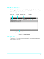
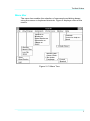
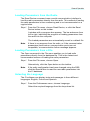
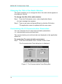
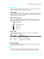
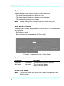
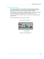
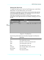
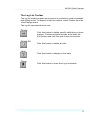
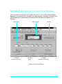
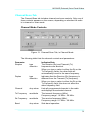
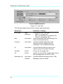
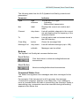
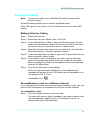
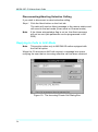
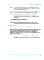
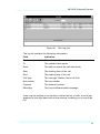
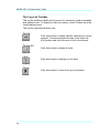
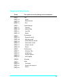
MICOM-2/2E HF-SSB Transceiver Computer Interface Software Motorola Inc., 1998 Motorola, Inc. Land Mobile Products Sector 1301 E. Algonquin Road Schaumburg, IL 60196 User ’ sGui de 68P02950C35-B April, 1998 MICOM-2/2E HF-SSB Transceiver Computer Interface Software Motorola Communications Israel Ltd. 1998 A subsidiary of Motorola Inc. All rights reserved. Land Mobile Products Sector 16 Kremenetski Street, Tel Aviv 67899 User ’ sGui de Printed in Israel, April, 1998 68P02950C35-B Table of Contents Acronyms and Abbreviations............................................................. vii Introduction ..............................................................................................1 Application.................................................................................................1 Prerequisites .............................................................................................1 Computer Interface Contents....................................................................1 Computer Configuration Requirements ....................................................2 Computer Support.....................................................................................2 Getting Started .........................................................................................3 General .....................................................................................................3 How to Install the Software .......................................................................3 How to Connect the Radio to your Computer ...........................................3 How to Start the Computer Interface Application ......................................3 The Main Window ....................................................................................5 The Title Bar..............................................................................................5 Menu Bar...................................................................................................6 Tool Bar .....................................................................................................7 Application Status Line..............................................................................8 General Operation...................................................................................9 General .....................................................................................................9 Loading the Control Panel.........................................................................9 Loading Parameters from the Radio.......................................................10 Loading Parameters from a File .............................................................10 Selecting the Language ..........................................................................10 Changing the Title of the Radio Window................................................. 11 Customizing the Computer Interface Communication Parameters ........ 11 Radio Communication Parameters.........................................................13 Resetting the Radio.................................................................................13 iii MICOM-2 / 2 ECI So f t wa r eUs e r ’ sGu i d e MICOM-2 (Basic) Control Panel Window ........................................15 Radio Display ..........................................................................................16 LCD Display.........................................................................................16 Status Annunciators .............................................................................16 Radio LEDs..........................................................................................16 Minimize Button ...................................................................................16 Clarifier....................................................................................................17 The Card Board ......................................................................................17 Channel/Scan Tab...................................................................................17 Channel Mode Controls .......................................................................17 Status Line ...........................................................................................19 Scan Mode Controls ............................................................................19 Command Status Line .........................................................................20 Buttons.................................................................................................21 Link Tab...................................................................................................21 Link Mode Controls..............................................................................22 Buttons.................................................................................................23 Command Status Line .........................................................................23 MICOM-2 (Basic) Operation................................................................25 General ...................................................................................................25 Turning Squelch On or Off ......................................................................25 Setting the Clarifier..................................................................................26 Selecting and Configuring a Channel......................................................27 Setting the Priority Channel ....................................................................28 Selecting a Group and Scanning ............................................................28 Entering Scan Mode ............................................................................28 Exiting Scan Mode...............................................................................28 Activating/Deactivating the SelCall Option..............................................29 Monitoring the Speaker ...........................................................................29 Entering SelCall Mode ............................................................................30 Making Selective Calling......................................................................30 Aborting Selective Calling....................................................................30 Replying to Calls in SelCall Mode ...........................................................31 iv Contents Using the Stack .......................................................................................31 Viewing the Stack List..........................................................................32 The Stack List Toolbar .........................................................................33 Replying to Unanswered Calls.............................................................34 Using the Log File ...................................................................................34 Viewing the Log File ............................................................................34 The Log List Toolbar ............................................................................36 MICOM-2E (Enhanced) Control Panel Window .............................37 Radio Display ..........................................................................................38 Mode Display .......................................................................................38 Information Display..............................................................................38 Icon Display .........................................................................................38 Transmission Bar (Tx) .........................................................................38 Receive/Transmit Level .......................................................................39 Minimize Button ...................................................................................39 Clarifier....................................................................................................39 Notch Filter..............................................................................................39 The Card Board ......................................................................................39 Channel/Scan Tab...................................................................................40 Channel Mode Controls .......................................................................40 Status Line ...........................................................................................42 Scan Mode Controls ............................................................................42 Command Status Line .........................................................................43 Buttons.................................................................................................44 Link Tab...................................................................................................44 Buttons.................................................................................................46 Command Status Line .........................................................................46 Update Link Quality Tab ..........................................................................47 Buttons.................................................................................................48 Command Status Line .........................................................................48 v MICOM-2 / 2 ECI So f t wa r eUs e r ’ sGu i d e MICOM-2E (Enhanced) Operation.....................................................49 General ...................................................................................................49 Turning Squelch On or Off ......................................................................50 Turning the Noise Blanker On or Off.......................................................50 Turning the Attenuator On or Off.............................................................50 Turning the Clipper On or Off..................................................................50 Setting the Clarifier..................................................................................50 Setting the Notch Filter............................................................................51 Selecting and Configuring a Channel......................................................52 Setting the Priority Channel ....................................................................54 Selecting a Group and Scanning ............................................................54 Entering Scan Mode ............................................................................54 Exiting Scan Mode...............................................................................54 Activating/Deactivating the ALE Option...................................................55 Monitoring the Speaker ...........................................................................55 Entering ALE Mode .................................................................................56 Making Selective Calling......................................................................56 Re-establishing a link on a different channel.......................................56 Disconnecting/Aborting Selective Calling ............................................57 Replying to Calls in ALE Mode ................................................................57 Setting Sounding ON and OFF ...............................................................58 Bidirectional Transmission ......................................................................59 Using the Stack .......................................................................................60 Viewing the Stack List..........................................................................61 The Stack List Toolbar .........................................................................62 Replying to Unanswered Calls.............................................................63 Using the Log File ...................................................................................63 Viewing the Log File ............................................................................63 The Log List Toolbar ............................................................................65 Keyboard Shortcuts .................................................................................66 vi Acronyms and Abbreviations AGC Automatic Gain Control ALE Automatic Link Establishment AME Amplitude Modulation Equivalent ARQ Automatic Repeat Request BDIR Bidirectional CI Computer Interface HF High Frequency LCD Liquid Crystal Display LED Light Emitting Diode LSB Lower Side Band Net Network PLT Pilot (mode) RSS Radio Service Software Rx Receive SelCall Selective Calling SQ Squelch Tx Transmit ULQ Update Link Quality USB Upper Side Band vii Introduction Application The MICOM-2/2E is a high performance, DSP-based, multi-purpose HF-SSB radio. It is intended for use in voice, data, and fax operation, in mobile or base station configurations. The MICOM-2/2E is operated from its integral front panel or remotely via a personal computer. It can be integrated into a large variety of advanced systems such as data and fax networks, VHF-UHF-microwave and telephone interconnect, high power (400W/1000W) systems, and so on. TheComput erI nt er f ace( CI )user ’ sgui dei sdesi gnedf oruser swho wish to control the MICOM-2/2E radio from a remote or local location, using a personal computer (IBM PC or compatible). Important: For more information on the MICOM-2/2E options and on howv ar i ousf unct i onsdescr i bedi nt hi sUser ’ sGui de,suchasscanni ng, groups, selective calling, nets, and so on, see any of the following manuals relevant to your specific equipment: MICOM-2HFSSBTr anscei v er ,Owner ’ sManual( 68P02941C60) MICOM-2 HF SSB Transceiver Digital Selective Calling Option (68P02950C95) MICOM-2EHFSSBTr anscei v er ,Owner ’ sManual( 68P02952C60) It is highly recommended that you read these manuals and familiarize yourself with the functions of the MICOM-2/2E prior to using the CI application. Prerequisites To use the CI software to control the radio, a basic working knowledge of Microsoft Windows is recommended. If you are new to the Windows operating environment, you should learn Windows fundamentals – using the mouse, working with windows, and opening and closing documents –before you begin to work with the CI software. Computer Interface Contents The CI option (Motorola part no. S947) consists of the following: 1. Application software, available on 3½ inch diskettes 2. Thi sUser ’ sGui de( 68P02950C35) 3. An RS232 cable (FKN4617A). 1 MICOM-2 / 2 ECI So f t wa r eUs e r ’ sGu i d e The CI option can also be ordered as a field retrofit kit. In this case, the radio model must be stated when ordering the kit, as follows: For Micom-2 (Basic): Motorola part no. FLN2423 For Micom-2E (Enhanced): Motorola part no. FLN2423 Computer Configuration Requirements In order to communicate with the radio using the CI, an IBM-PC with the following configuration is required: 486DX/66 MHz or higher 16 MB RAM A monitor with a minimum resolution of 800x600 and at least 256 colors Microsoft Windows operating system version 3.11 Free hard disk space of at least 12 Mbytes One 3½ inch, 1.44 MB floppy disk drive One serial communication port A mouse Computer Support If you encounter a problem, first check your hardware setup. Problems requiring additional analysis should be referred to: Motorola Radio Support Center 3761 S. Central Avenue Rockford, IL 61102, USA Tel: (847) 725 4830 or (800) 227 6772 Global Data Specialists 3707 E. Broadway Road, Suite 2, Phoenix, AZ 85040, USA Tel: (602) 437 4331 Fax: (602) 437 1858 US Federal customers should contact: Motorola USFG Depot 7940 Penn Randall Place Upper Marlboro, MD 20772 Tel: (301) 736 4300 or (800) 969 6680 Fax: (301) 735 7414 or (800) 784 4133 2 Getting Started General This section guides you in the installation of the MICOM-2/2E Computer Interface Software and in the connection of the radio to your computer. How to Install the Software The Computer Interface Software is shipped to you on 3½ inch diskettes. To set the software up on a hard disk, proceed as follows: 1. Insert the CI Install disk (disk 1) into drive A. 2. Enter Windows. If Windows is already running, close any open applications. 3. From the File menu, choose Run 4. Type a:setup (or b:setup) and then press [Enter]. 5. Follow instructions on the screen. If the installation process is completed successfully, the CI software is now installed on your hard disk and a new program group has been created in your Program Manager window named MICOM-2/2E Computer Interface. How to Connect the Radio to your Computer Connectt he“ r adi o”si deoft heRS232cabl et ot heAccessor yconnect or ont her adi or earpanel .Connectt he“ comput er ”si deoft heRS232 cable to the PC serial port. If necessary, use a D25-to-D9 adapter. How to Start the Computer Interface Application 1. Tur nony ourcomput er ;att heDOSpr ompt ,t y pe“ wi n”andpr ess [Enter]. 2. Connect your radio to the computer. 3. Turn the radio on. 4. Double-click the Computer Interface icon. The application starts to run, and after a few seconds the main window of the CI appears on the screen. 3 The Main Window After the application has completed initialization, the CI main window appears. The main window is comprised of a title bar, a menu bar, a tool bar and an application status line. Menu Bar Title Bar Window Title Tool Bar Application Status Line Figure 1. CI Main Window The Title Bar The title bar of the main window indicates the radio name or any other name given by the user. 4 The Main Window Menu Bar The menu bar enables the selection of commands and dialog boxes, using the mouse or keyboard shortcuts. Figure 2 displays a tree of the menus. Figure 2. CI Menu Tree 5 MICOM-2 / 2 ECI So f t wa r eUs e r ’ sGu i d e Tool Bar The tool bar enables the user access to commonly used commands and dialog boxes, by clicking an icon (button). The icons available in both MICOM2 and MICOM2E are: 6 Open Opens an existing radio parameter file (default file) Read Device Loads parameters from the radio Communication Ports Selects the baud rate and the computer communication port (dialog box) Squelch ON/OFF Turns the squelch circuit on or off. When squelch is on, the speaker remains muted until the radio detects a valid signal in its input. When squelch is off, the speaker emits all signals, including noise. Monitor Mute ON/OFF Mutes or unmutes the speaker in SelCall/ALE mode. The Main Window Special icons available only in MICOM2E are: Noise Blanker ON/OFF Activates/deactivates repetitive noise filter. Clipper ON/OFF When on, uses voice processing to boost the output power. Attenuator ON/OFF When on, attenuates the incoming signal by 20dB. Help Displays on-line help. Exit Exits the CI application Application Status Line This line contains five fields that describe the application status: Status: Displays the position of the mouse cursor. File/Radio: Di spl ay s“ Fi l e”i ft heappl i cat i onl oadst her adi odat abase f r om af i l e;ot her wi se,“ Radi o”i sdi spl ay ed. S/N: Di spl ay st her adi o’ sser i alnumber . Code: Di spl ay st her adi o’ scode( t hi scodecannotbechanged) . COM: Displays the communication port and baud rate. 7 General Operation General This section describes how to: Load the control panel Load parameters from the radio Load radio parameters from a file In addition, general CI operations are described, including: Renaming the application Selecting a language Customizing the CI serial communication parameters Resetting the MICOM-2/2E Radio Loading the Control Panel When you run the CI application, the main window opens while the program examines whether the CI data base is empty or contains entries. If the data base is empty, a black screen opens. If there are entries in the database, the CI automatically loads the CI control panel. Note: The CI application is shipped from the factory with an empty database file. When you first open the application, the Open command in the File menu and the Open button are disabled. Once you have read the radio parameters from the radio using the Read Device command, they are automatically saved in the database file, which will then be available through the Open command. 8 General Operation Loading Parameters from the Radio The Read Device command uses a serial communication interface to load the radio parameters directly from the radio. This method of loading the radio parameters is time consuming and is not recommended on a regular basis. Step 1. From the File menu, choose Read Device, or click the Read Device button on the toolbar. A window with a progress bar appears. The bar advances from left to right, indicating the progress of loading parameters from the radio into the computer. The loaded parameters are automatically saved in a default file. Note: If there is no response from the radio, or if the communication parameters (baud rate or communication ports) are not compatible, a communication failure message appears. Loading Parameters from a File The Open command in the File menu enables you to load radio parameters directly from the database file. This is the fastest and recommended manner of loading the radio parameters. Step 1. From the File menu, choose Open. Alternatively, click the Open button on the toolbar. Note: If the radio configuration has been changed using the RSS, click the Read button to read the new radio parameters into the CI database. Selecting the Language The CI software can display texts and messages in three different languages: English, French and Spanish. Step 1. From the Preferences menu, choose Language. Select the required language from the drop-down list. 9 MICOM-2 / 2 ECI So f t wa r eUs e r ’ sGu i d e Changing the Title of the Radio Window This option enables you to change the title of the radio which appears in t hewi ndow’ st i t l ebar . To change the title of the radio window: Step 1. From the Preferences menu, select Application Name. An input message box appears. Step 2. Type a new name and press [Enter] or click the OK button. The application name is replaced with the new name. Customizing the CI Communication Parameters You can customize the CI serial communication parameters, i.e., communication ports and baud rate. The communication port and baud rate are displayed on the application status line. To customize CI communication parameters: Step 1. From the Preferences menu, choose Comm. Ports. The Communication Ports dialog box is displayed. Figure 3. The Communication Ports Dialog Box 10 General Operation The following table lists the Communication Ports window parameters Parameter Specifies Baud Rate The serial communication baud rate. To select a baud rate, click one of the options (1200/2400/4800/9600 bps). Note: If the MICOM-2/2E is intended for operation with HF-Modem type CCIR-476-3 in ARQ mode, the serial communication baud rate must be set to 9600 bps. Comm. Port The serial communication ports. Select a port from the drop-down list. Note: If all ports are being used by other applications, close such applications to free the ports. Comm. test button Note: Prior to any communication attempt, verify that the communication cable is firmly connected on both sides (radio and PC), and that the radio is on. To verify the selected baud rate and communication port, enable radio communication and click the Check button. The Communication Progress window is displayed. You can stop this process at any time by clicking the Abort button. If you selected an incorrect baud rate or communication port, a communication failure prompt appears on the screen, indicating that you must select a new value. 11 MICOM-2 / 2 ECI So f t wa r eUs e r ’ sGu i d e Radio Communication Parameters The MICOM-2/2E radio has the following communication parameters: Baud rate: 1200,2400,4800 or 9600 (user selectable) Data bits: 8 (factory setting) Stop bits: 1 (factory setting) Parity: Odd (factory setting) Resetting the Radio This option enables you to reset the MICOM-2/2E radio. Step 1. From the Preferences menu, select User>Reset. The radio receives the reset command and initializes itself to the last stable state. The radio then sends a message to the application to synchronize the displayed parameters. 12 General Operation 13 MICOM-2 (Basic) Control Panel Window Once the radio parameters are loaded into the CI, the control panel window appears. The control panel includes the radio display, a clarifier, and a card board (comprised of a channel tab and a link tab). Card Board Tab Label (Channel or Scan) Radio Display Clarifier Tab Label (Link) Figure 4. Control Panel 14 MICOM-2 (Basic) Control Panel Window Radio Display This box simulates the LCD display of the radio, including an LCD text and icon display, LEDs, and a Minimize button. LCD Display The LCD display consists of eight characters, indicating the radio status and providing information such as channel or scan mode, transmission, clarifier, frequency, and radio errors. Status Annunciators Above the character display are five status icons which indicate five parameters of the radio operating status: clarifier, noise blanker (NB), monitor, stack, and alarm. Clarifier icon Noise blanker icon Monitor icon Stack icon Alarm icon Radio LEDs The three LEDs indicate the radio PTT condition, radio mode and squelch condition, as follows: LED Color Lights when... Tx Red the PTT key is pressed. LSB Orange the radio is in LSB mode. SQ Green the squelch circuit is active. Minimize Button The minimize button enables you to reduce the CI main window so that only the radio display is visible. Clarifier The clarifier enables fine tuning of the receive frequency to improve voice quality when the incoming signal is slightly off frequency. The 15 MICOM-2 / 2 ECI So f t wa r eUs e r ’ sGu i d e clarifier can be turned off and is automatically disabled during transmission. The upper and the lower frequency deviation limits are ±200Hz. Note: When the radio switches to a new channel, the clarifier is automatically turned off. The Card Board The card board contains all information and variable parameters necessary to control the radio in various modes and activities such as channel mode, scan mode, selective call, replying calls and so on. The card board consists of two tabs, Channel/Scan and Link. The Channel/Scan tab is used for channel and scan modes, and the Link tab is used for selective calling, link information, display of unanswered calls, and reply to unanswered calls. Note: In MICOM-2 radios equipped with the SelCall option, only the Channel/Scan tab is visible when SelCall mode is off. Channel/Scan Tab The Channel/Scan tab includes channel and scan controls. Only one of these controls appears on the screen, depending on whether the radio is in channel or scan mode. Channel Mode Controls Figure 5. Channel/Scan Tab, in Channel Mode The following table lists the channel controls and parameters: Parameter Channel 16 drop down Indicates The number of the selected channel. MICOM-2 (Basic) Control Panel Window Tx Frequency read-only The transmit frequency (MHz). Frequency range: 1.6 MHz –30 MHz. Rx Frequency read-only The receive frequency (MHz). Frequency range: 0.1 MHz –30 MHz. Band drop down Side band operation: Upper Side Band or Lower Side Band. AGC read-only Automatic (receive) Gain Control: Slow –used for voice communication Fast –generally used for data transmission (only when required by the HF data modem). Tx Power read-only Mode read-only Carrier reinsertion level: SSB (Single Side Band) –The radio operates on the upper side band with suppressed carrier. AME (Amplitude Modulation Equivalent) – The radio operates on the upper/lower side band with the carrier inserted 6 dB below peak envelope power. PLT (Pilot mode) –The radio operates on the upper/lower side band with the carrier inserted 15 dB below peak envelope power. Bandwidth read-only The bandwidth of the current channel. Transmit power level: low 25 Watt high 100 Watt medium 60 Watt max. 125 Watt Note: When a 400W/1000W amplifier is connected to the radio, the transmitted power is 400W/1000W and not as displayed in the Tx Power box. Note: MICOM-2 has only one bandwidth –2700 Hz. 17 MICOM-2 / 2 ECI So f t wa r eUs e r ’ sGu i d e Status Line In the following cases, an error appears in the status line: The typed channel/frequency is out of range. The typed channel/frequency is not a numerical value. The channel/frequency box is empty. Note: If there is an error in the typed channel or frequency, you cannot press the set button. Scan Mode Controls If the MICOM-2 radio is equipped with a SelCall option, two scan modes are available: SelCall scan mode Basic scan mode (enabled when SelCall is off) Figure 6. Channel/Scan tab, in Scan Mode The following table lists the channel controls and parameters: Parameter Indicates Group/Net drop down The selected Group/Net number Net Name read-only The current Net Name (only in SelCall mode) SelCall Scan mode Note: 18 This section refers only to MICOM-2 radios equipped with the SelCall option. MICOM-2 (Basic) Control Panel Window When the SelCall mode is operating, the MICOM-2 can automatically scan up to five nets (1, 2, 3, 4 and 5), each with up to 100 channels. The nets are pre-programmed in the radio (using the RSS for SelCall), and each net has an assigned name (network address). In the CI, you can switch from one net to another using the Scan Group drop-down menu. Basic Scan mode When the SelCall mode is off, or if your radio is not equipped with the SelCall option, the MICOM-2 operates in basic mode and can automatically scan up to five groups (A, B, C, D and E), each with up to 100 channels. The groups are pre-pr ogr ammedi nt her adi o( usi ngt her adi o’ sRSS, depending on the radio model). In the CI, you can switch from one group to another by selecting a new group in the Scan Group dropdown menu. Anaddi t i onalchannelcanbepr ogr ammedasa“ guar d”channel .Thi s channel is scanned more frequently than the other channels. Command Status Line The Status line registers error messages and other messages for the user. For example, if the last request is still in process, the message “ Commandi npr ogr ess”appear si nt heSt at usl i ne.I fy ouat t emptt o i ssueacommandwhi l et her adi oi st r ansmi t t i ng,t hemessage“ Radio is t r ansmi t t i ngnow,commandscannotbeexecut eddur i ngt r ansmi t t i ng” appears in the Status line. 19 MICOM-2 / 2 ECI So f t wa r eUs e r ’ sGu i d e Buttons The Channel/Scan tab command buttons are: Set Button Click this button to download the selected channel number and its parameters to the radio. Priority Button Instantaneously changes the current channel to a pre-defined priority channel, overriding the current status and the standard operating procedure. Start/Stop Scan Button The Start Scan button initiates scanning of channels in the currently selected group. This is considered the Radio Scanning state. The Stop Scan button stops radio scanning. The radio status switches to Channel mode. Link Tab Note: This paragraph refers only to MICOM-2 radios equipped with the SelCall option. In radios equipped with the SelCall option, this tab is visible only if the SelCall option is active. The SelCall Link tab includes all SelCall controls and displays all SelCall status information. In the SelCall tab, you can: 20 Select the net, channel, and station Perform selective calling Display unanswered calls Reply unanswered calls. MICOM-2 (Basic) Control Panel Window Link Mode Controls Figure 7. Link Tab The following table lists the SelCall controls and parameters: Parameter Indicates Call Type type selection The required selective call type: Station –private call Net –all members in a specific net All Call –broadcast call Lists all available nets and displays the name of the selected net. Net drop down Channel drop down Lists all available channels in the selected net and displays the Rx frequency of the selected channel. To drop down Lists all station and net names stored in the SelCall directory. 21 MICOM-2 / 2 ECI So f t wa r eUs e r ’ sGu i d e Buttons The SelCall tab command buttons are: Send Button Click this button to initiate Selective Calling. Stack Button Displays all unanswered calls in SelCall mode. Abort Button Disconnects/aborts selective calling. Command Status Line The Status line registers error messages and other messages for the user. For example, if the last request is still in process, the message “ Commandi npr ogr ess”appear si nt heSt at usline. If you attempt to i ssueacommandwhi l et her adi oi st r ansmi t t i ng,t hemessage“ Radi oi s t r ansmi t t i ngnow,commandscannotbeexecut eddur i ngt r ansmi t t i ng” appears in the Status line. 22 MICOM-2 (Basic) Control Panel Window 23 MICOM-2 (Basic) Operation General This section describes how to operate the MICOM-2 radio using the CI (Computer Interface) software. The operations available depend on the specific radio model. For all models, the CI enables the user to: Turn the squelch on or off Set the clarifier Select or change a channel and change its configuration Set the priority channel Select or change a group and start or stop scanning For MICOM-2 radios equipped with the SelCall option, the CI enables the user to: Activate/Deactivate the SelCall option Monitor the speaker Initiate selective calling Reply to calls in SelCall mode Use the stack option Reply to unanswered calls View the SelCall log file Turning Squelch On or Off To turn squelch on or off, click the squelch button or choose Squelch from the Commands menu. The squelch is a toggle button, i.e. each time you click it, the squelch circuit changes its state from on to off and vice versa. You can set the squelch state regardless of the current mode of the CI application. 24 MICOM-2 (Basic) Operation Setting the Clarifier The clarifier enables fine tuning of the receive frequency to improve voice quality when the incoming signal is slightly off frequency. The upper and the lower frequency deviation limits are ±200Hz. To change the clarifier setting in predefined steps, use the left and right buttons to decrease/increase the clarifier deviation by 10 Hz. To set the clarifier at a specific frequency deviation, drag and drop the coarse button. T osett hecl ar i f i ert oof f ,cl i ckont he“ 0”di gi t . Click "0" to turn clarifier off Coarse Button Figure 8. The Clarifier Box 25 MICOM-2 / 2 ECI So f t wa r eUs e r ’ sGu i d e Selecting and Configuring a Channel The MICOM-2 radio can have up to 100 programmed channels. Note: The radio can only be set to channels that have been programmed using the Radio Service Software (RSS). To select a new channel using the Channel box: Step 1. Open the Channel/Scan tab. Note: If the radio is in Scan mode, press the Scan button to return t oChannelmode.Theact i v et abwi l lbe“ Channel ” . Step 2. Click the Channel drop-down list and select the required channel from the list. If a scroll bar appears inside the list box, this means that there are more channels than displayed. Use the scroll bar to scroll the list. Alternatively, you can click inside the Channel box and type the required channel number. Selecting a new channel will automatically change all other fields in the di al ogboxt ov al uesst or edi nt hecomput er ’ smemor yf ort hi schannel . Note: When new channel settings and configurations are selected, these are displayed on screen, but are not reflected in the radio. To update the radio configuration, click the Set button or press [Enter]. To select a different band for the current channel: Step 1. Click the Band drop-down list and select the required band from the list. Al t er nat i v el y ,cl i cki nsi det heBandboxandt y pe“ U”f orUSB( uppersi de band)or“ L”f orLSB( l owersi deband) . Note: When new band settings and configurations are selected, these are displayed on screen, but are not reflected in the radio. To update the radio configuration, click the Set button or press [Enter]. Setting the Priority Channel To set the radio to work with the priority channel, click the Priority button and wait for radio to respond. The radio changes its current channel to 26 MICOM-2 (Basic) Operation the pre-defined priority channel, overriding the current status and the standard operating procedure. You can select a priority channel regardless of the current mode of the CI application. Selecting a Group and Scanning To select a scan group: Step 1. Click the Scan Group drop-down list and select the required group (A, B, C, D, E, or SelCall Net 1,2,..5, if your radio includes the SelCall option) from the list. Note: When the radio is in scanning mode, each time you select a new group, the radio changes its scan group immediately. Entering Scan Mode To start scanning, click the Start Scan button. The tab name and configuration changes to the Scan tab. The radio enters Scan mode and begins to scan channels in the currently selected group. Exiting Scan Mode There are three different ways to stop scanning: Stop Scan Click the Stop Scan button. The radio stops scanning, the tab name and configuration changes to the Channel tab and the radio status reverts to Channel mode. Priority Click the Priority button. The radio stops scanning, reverts to Channel mode, and sets the priority channel. PTT Press the PTT (microphone) button. The radio immediately stops scanning at the last channel reached. Note: The PTT option is available only when the radio is in basic scan mode. Activating/Deactivating the SelCall Option Note: This section refers only to MICOM-2 radios equipped with the SelCall option. 27 MICOM-2 / 2 ECI So f t wa r eUs e r ’ sGu i d e You can activate or deactivate the Selcall option from the CI application. To activate/deactivate the SelCall option: Step 1. From the Preferences menu select SelCall Option. Wait until the application has completed any changes in the control settings before proceeding. Monitoring the Speaker Note: This section refers only to MICOM-2 radios equipped with the SelCall option. When SelCall is active, you can switch the speaker on or off. Step 1. From the Command menu, select Monitor. Alternatively, click the Monitor button on the toolbar. When Monitor is activated, the MON icon appear on the radio LCD display. The Monitor button toggles from on to off and vice versa. Note: 28 The monitor function is only available when the SelCall mode is activated. MICOM-2 (Basic) Operation Entering SelCall Mode Note: This section refers only to MICOM-2 radios equipped with the SelCall option. Selective calling enables you to contact predefined nets. If SelCall is not active, from the Preferences menu, select SelCall. Making Selective Calling Step 1. Select the Link tab. Step 2. Select the call type: Station, Net, or All Call. Step 3. Open the Net drop-down list and select the identification number of the net you wish to call from the net list box. Alternatively, you can click inside the net box and type the net number. Step 1. Open the Channel drop-down list and select a channel. Step 2. If you selected call type Station, open the To drop-down list and select a specific station name. Step 3. Click the Send button to start calling. Aborting Selective Calling Step 1. Click the Abort button on the Link tab. The radio will send an Abort message to the remote station and will revert to the last mode (Scan mode or Channel mode). Note: If the HOME acknowledge flag is not on, the Abort message will not be sent to the remote radio (this parameter can be programmed in the RSS). 29 MICOM-2 / 2 ECI So f t wa r eUs e r ’ sGu i d e Replying to Calls in SelCall Mode Note: This section refers only to MICOM-2 radios equipped with the SelCall option. When the CI receives a SelCall request, a message box opens, notifying the user that an incoming selective call has been received. Figure 9. The Incoming Private Call Dialog Box You can confirm or reject the call: To confirm the call, click the OK button in the message box. This will cause the radio to confirm the call and establish the link. To reject the call, click the Abort button in the message box. This will cause the radio to send a reject message to the station that performed the call and to revert the radio to its previous state. Using the Stack Note: This section refers only to MICOM-2 radios equipped with the SelCall option. Unanswered calls in SelCall mode are stored in the Stack, which can save up to 200 calls (depending on the log file size). When at least one unanswered call is registered, the Stack button in the Link tab is activated. If the stack is empty, i.e., there are no unanswered calls, the Stack button is disabled. Note: 30 The contents of the Stack are not necessarily identical to those of the radio cache. The Stack is only updated when the application is running and can store up to 200 unanswered calls. MICOM-2 (Basic) Operation Viewing the Stack List To display the Stack log file, from the View/Change menu, select Stack. Alternatively, click the Stack button in the Link tab. A dialog box containing the list of station names and the date and time of the unanswered calls appears. You can answer these calls directly from the list, delete selected entries or all entries. If the Stack list window is too small to contain the list of calls, a scroll bar appears on the right hand side of the window, enabling you to scroll the list. Row Selector Figure 10. The Stack List The following table details the information displayed in the Stack list: Field Indication From Thecal l er ’ sst at i onname To The called station name Date The date on which the call was made Start The starting time of the call End The ending time of the call Call type The call type: Station, Net or All Call Net number The net number Channel The channel number 31 MICOM-2 / 2 ECI So f t wa r eUs e r ’ sGu i d e The Stack List Toolbar The stack list toolbar enables quick access to commonly used commands and dialog boxes. To display or hide the toolbar, select Toolbar from the View/Change menu. The stack list command buttons are: Delete Click this button to delete specific calls that you have marked. To select multiple records, hold down the [Ctrl] button and click the rows in the row selector. Delete All Click this button to delete all unanswered calls. Reply Click this button to reply to an unanswered call that you have marked (one call only). Help Click this button to display on-line help. Close Click this button to close the Stack List window. 32 MICOM-2 (Basic) Operation Replying to Unanswered Calls Note: This section refers only to MICOM-2 radios equipped with the SelCall option. To reply to an unanswered call registered in the Stack list: Step 1. Click the listing to which you wish to reply. Step 2. Click the Reply button in the Stack list toolbar. The CI application automatically performs the following sequence: The marked listing is deleted from the Stack list. The Stack list is closed. The Station name and all relevant information (net and channel) are automatically loaded into the Link tab fields. Step 3. Click the Send button to initiate the call. Using the Log File Note: This section refers only to MICOM-2 radios equipped with the SelCall option. Viewing the Log File The Log viewer enables you to view the log of all incoming and outgoing calls. To open the Log viewer window, from the View/Change menu, select Log File. 33 MICOM-2 / 2 ECI So f t wa r eUs e r ’ sGu i d e Figure 11. The Log List The log list contains the following information: Field Indication From Thecal l er ’ sst at i onname To The called station name Date The date on which the call was made Start The starting time of the call End The ending time of the call Call type The call type: Station, Net or All Call Net number The net number Channel The channel number If the Log list window is too small to contain the list of calls, a scroll bar appears on the right hand side of the window, enabling you to scroll the list. 34 MICOM-2 (Basic) Operation The Log List Toolbar The log list toolbar enables quick access to commonly used commands and dialog boxes. To display or hide the toolbar, select Toolbar from the View/Change menu. The log list command buttons are: Delete Click this button to delete specific calls that you have marked. To select multiple records, hold down the [Ctrl] button and click the rows in the row selector. Delete All Click this button to delete all calls. Help Click this button to display on-line help. Close Click this button to close the Log List window. 35 MICOM-2E (Enhanced) Control Panel Window Once the radio parameters are loaded into the CI, the control panel window appears. The control panel includes the radio display, a clarifier, a Notch Filter, and a card board (comprised of a channel tab, link tab and Update Link Quality). Card Board Tab Label (Channel or Scan) Radio Display Tab Label (Link) Clarifier Tab Label (Update Link Quality) Figure 12. Control Panel 36 MICOM-2E (Enhanced) Control Panel Window Radio Display This box simulates the LCD display of the radio, and includes the following elements: two textual displays (mode and information), an icon display, a transmission (Tx) bar, a receive/transmit level indicator, and a minimize button. Mode Display Indicates the current working mode, for example CH# for channel mode, Freq. For frequency mode, ALE for ALE mode and so on. Information Display Information pertaining to the operation presently being performed in the current working mode. For example: when the radio is in Channel Mode, this line displays the actual frequency of the specified channel. Icon Display Above the textual display is the Icon Display, where any of the ten following icons can be displayed, indicating various parameters of the r adi o’ soper at i ngst at us,asf ol l ows: USB LSB Squelch Monitor Noise Blanker Clarifier Notch Filter Bandwidth AGC Alarm Transmission Bar (Tx) The transmission bar is displayed when the PTT button is pressed, indicating that the MICOM-2E is transmitting. 37 MICOM-2 / 2 ECI So f t wa r eUs e r ’ sGu i d e Receive/Transmit Level In Transmit mode, this bar displays the output power level. In Receive mode, this bar displays the level of the received signal, when the receive level button is pressed. Minimize Button The minimize button enables you to reduce the main window of the CI so that only the radio display is visible. Clarifier The clarifier enables fine tuning of the receive frequency to improve voice quality when the incoming signal is slightly off frequency. The clarifier can be turned off and is automatically disabled during transmission. The upper and the lower frequency deviation limits are ±200Hz. Note: When the radio switches to a new channel, the clarifier is automatically turned off. Notch Filter The notch filter reduces noise in a specific user-defined range within the channel bandwidth, in order to improve voice quality. The notch filter can be turned off and is automatically disabled during transmission. Note: When the radio switches to a new channel, the notch filter is automatically turned off. The Card Board The card board contains all information and variable parameters necessary to control the radio in various modes and activities such as channel mode, scan mode, selective call, replying calls and so on. The card board consists of three tabs, Channel/Scan, Link and Update Link Quality. The Channel/Scan tab is used for channel and scan modes. The Link tab is used for selective calling, link information, display of unanswered calls, and reply to unanswered calls. The Update Link Quality tab is used for sounding and channel score management in ALE mode. Note: 38 In MICOM-2E radios equipped with the ALE option, only the Channel/Scan tab is visible when the ALE mode is turned off. MICOM-2E (Enhanced) Control Panel Window Channel/Scan Tab The Channel/Scan tab includes channel and scan controls. Only one of these controls appears on the screen, depending on whether the radio is in channel or scan mode. Channel Mode Controls Figure 13. Channel/Scan Tab, in Channel Mode The following table lists the channel controls and parameters: Parameter Simplex type selection Indicates/Sets The Receive (Rx) and Transmit (Tx) frequencies are identical. When you type a value in either the Rx or the Tx Frequency fields, the other field will automatically be set to the same frequency. Duplex type selection Indicates that the Receive (Rx) frequency is different from the Transmit (Tx) frequency. When you type a value in either the Rx or the Tx Frequency field, this does not affect the other frequency field. Channel drop down Lists all programmed channels in the radio and displays the selected channel. Tx Frequency read/write The transmit frequency (MHz). Frequency range: 1.6 MHz –30 MHz. Rx Frequency read/write The receive frequency (MHz). Frequency range: 0.1 MHz –30 MHz. Band drop down Side band operation: 39 MICOM-2 / 2 ECI So f t wa r eUs e r ’ sGu i d e Parameter Indicates/Sets Upper Side Band or Lower Side Band. AGC drop down Tx Power drop down Mode drop down Bandwidth drop down 40 Automatic (receive) Gain Control: Slow –used for voice communication Fast –generally used for data transmission (only when required by the HF data modem). Transmit power level: low 25 Watt medium 60 Watt high 100 Watt max. 125 Watt Note: When a 400W/1000W amplifier is connected to the radio, the transmitted power is 400W/1000W and not as displayed in the Tx Power box. Carrier reinsertion level: SSB (Single Side Band) –The radio operates on the upper side band with suppressed carrier. AME (Amplitude Modulation Equivalent) – The radio operates on the upper/lower side band with the carrier inserted 6 dB below peak envelope power. PLT (Pilot mode) –The radio operates on the upper/lower side band with the carrier inserted 15 dB below peak envelope power. The bandwidth of the current channel, as follows: Display Range 2700 (350-2700)Hz 3300 (350-3300)Hz LSM (1450-1950)Hz C.W. (650-1150)Hz MICOM-2E (Enhanced) Control Panel Window Status Line In the following cases, an error message appears in the status line: The typed channel/frequency is out of range. The typed channel/frequency is not a numerical value. The channel/frequency box is empty. Note: If there is an error in the typed channel or frequency, you cannot press the set button. Scan Mode Controls If the MICOM-2E radio is equipped with an ALE option, two scan modes are available: ALE scan mode Basic scan mode (enabled when ALE is off) Figure 14. Channel/Scan Tab, in Scan Mode The following table lists the channel controls and parameters: Parameter Indicates Group/Net drop down The selected Group/Net number Net Name read-only The current Net Name (only in ALE mode) 41 MICOM-2 / 2 ECI So f t wa r eUs e r ’ sGu i d e ALE Scan mode Note: This section refers only to MICOM-2E radios equipped with the ALE option. When the ALE mode is operating, the MICOM-2E can automatically scan up to twenty nets (1 to 20), each with up to 200 channels. The nets are pre-programmed in the radio (using the RSS for ALE), and each net has an assigned name (network address and Self Address). In the CI, you can switch from one net to another using the Scan Group drop-down menu. Basic Scan mode When the ALE mode is off, or if your radio is not equipped with the ALE option, the MICOM-2E operates in basic mode and can automatically scan up to five groups (A, B, C, D and E), each with up to 200 channels. The groups are pre-pr ogr ammedi nt her adi o( usi ngt her adi o’ sRSS, depending on the radio model). In the CI, you can switch from one group to another by selecting a new group in the Scan Group dropdown menu. Anaddi t i onalchannelcanbepr ogr ammedasa“ guar d”channel .Thi s channel is scanned more frequently than the other channels. Command Status Line The Status line registers error messages and other messages for the user. For example, if the last request is still in process, the message “ Commandi npr ogr ess”appear si nt heSt at usl i ne.I fy ouat t emptt o i ssueacommandwhi l et her adi oi st r ansmi t t i ng,t hemessage“ Radi oi s t r ansmi t t i ngnow,commandscannotbeexecut eddur i ngt r ansmi t t i ng” appears in the Status line. 42 MICOM-2E (Enhanced) Control Panel Window Buttons The Channel/Scan tab command buttons are: Set Button Click this button to download the selected channel number and its parameters to the radio. Priority Button Instantaneously changes the current channel to a pre-defined priority channel, overriding the current status and the standard operating procedure. Start/Stop Scan Button The Start Scan button initiates scanning of channels in the currently selected group. This is considered the Radio Scanning state. The Stop Scan button stops radio scanning. The radio status switches to Channel mode. Link Tab Note: This paragraph refers only to MICOM-2E radios equipped with the ALE option. In radios equipped with the ALE option, this tab is visible only if the ALE option is active. The Link tab includes all ALE controls and displays all SelCall status information. In the Link tab, you can: Select the net, channel, station and message. Perform ALE calling. Display unanswered calls Reply unanswered calls. 43 MICOM-2 / 2 ECI So f t wa r eUs e r ’ sGu i d e Figure 15. Link Tab The following table lists the Link controls and parameters: Parameter 44 Indication / Setting Call Type type selection The required ALE call type: Station –private call Net –all members in a specific net All Call –broadcast call Lists all available nets and displays the name of the selected net. Net drop down Channel drop down Lists all available channels in the selected net and displays the Rx frequency of the selected channel. To drop down Lists all stations and the current net names stored in the ALE directory. Clr Msg button Clears the message field. Tel button I nser t st hewor d“ Di al ”att hebegi nni ngof the message field (for ASTIC use). Message List drop down Lists all defined messages (up to 100). editable Messages can be edited. MICOM-2E (Enhanced) Control Panel Window Buttons The Link tab command buttons are: Send Button Click this button to initiate ALE Calling. Stack Button Displays all unanswered calls in ALE mode. Replace Button Disconnects/aborts the ALE link and initiates ALE calling on a better channel. Abort Button Disconnects/aborts ALE calling. Command Status Line The Status line registers error messages and other messages for the user. For example, if the last request is still in process, the message “ Commandi npr ogr ess”appear si nt heSt at usl i ne.I fy ouat t emptt o i ssueacommandwhi l et her adi oi st r ansmi t t i ng,t hemessage“ Radi oi s t r ansmi t t i ngnow,commandscannotbeexecut eddur i ngt r ansmi t t i ng” appears in the Status line. 45 MICOM-2 / 2 ECI So f t wa r eUs e r ’ sGu i d e Update Link Quality Tab Note: This paragraph refers only to MICOM-2E radios equipped with the ALE option. In radios equipped with the ALE option, this tab is visible only if the ALE option is active. In the Update Link Quality tab, you can: Activate sounding. Perform bidirectional transmission Figure 16. Update Link Quality Tab 46 MICOM-2E (Enhanced) Control Panel Window The following table lists the ULQ (Update Link Quality) controls and parameters: Parameter Indicates Type type selection The required ULQ type: Sounding Bidirectional transmission Displays the current net number and name. Net label Channel drop down Lists all available channels in the current net and displays the Rx frequency of the selected channel. To drop down Lists all station and net names stored in the ALE directory. Clear Msg button Clears the message field. Message List drop down Lists all defined messages (up to 100). editable Messages can be edited. Buttons The Update Link Quality tab command buttons are: Send Button Click this button to initiate sounding/bidirectional transmission. Abort Button Aborts sounding/bidirectional transmission. Command Status Line The Status line registers error messages and other messages for the user. For example, if the last request is still in process, the message “ Commandi npr ogr ess”appear si nt heSt at usl i ne.I fy ouat t emptt o i ssueacommandwhi l et her adi oi st r ansmi t t i ng,t hemessage“ Radi oi s t r ansmi t t i ngnow,commandscannotbeexecut eddur i ngt r ansmi t t i ng” appears in the Status line. 47 MICOM-2E (Enhanced) Operation General This section describes how to operate the MICOM-2E radio using the Computer Interface software. Note: When the MICOM-2E radio is controlled by the CI, the radio keyboard is locked to prevent user interference. To enable keyboard functionality turn the radio off and on. For all models, the CI enables the user to: Turn the squelch on or off Turn the noise blanker on or off Turn the attenuator on or off Turn the clipper on or off Set the clarifier Set the notch filter Select or change a channel and change its configuration Set the priority channel Select or change a group and start or stop scanning For MICOM-2E radios equipped with the SelCall option, the CI enables the user to: Activate/deactivate ALE Option Monitor the speaker Initiate selective calling Reply to calls in ALE mode Use the stack option Reply to unanswered calls View the ALE log file 48 MICOM-2E (Enhanced) Operation Turning Squelch On or Off To turn squelch on or off, click the squelch button or choose Squelch from the Commands menu. The squelch is a toggle button, i.e. each time you click it, the squelch circuit changes its state from on to off and vice versa. You can set the squelch state regardless of the current mode of the CI application. Turning the Noise Blanker On or Off To turn noise blanker on or off, click the Noise Blanker button or select Noise Blanker from the Commands menu. The noise blanker button toggles from on to off and vice versa. Note: The noise blanker function is only available when the noise blanker option is enabled using the RSS. Turning the Attenuator On or Off To turn attenuator on or off, click the Atten (Attenuator) button or choose Attenuator from the Commands menu. The Atten button button toggles from on to off and vice versa. Turning the Clipper On or Off To turn clipper on or off, click the Clip (Clipper) button or choose Clipper from the Commands menu. The Clipper button toggles from on to off and vice versa. Setting the Clarifier The clarifier enables fine tuning of the receive frequency to improve voice quality when the incoming signal is slightly off frequency. The upper and the lower frequency deviation limits are ±200Hz. To change the clarifier setting in predefined steps, use the left and right buttons to decrease/increase the clarifier deviation by 10 Hz. To set the clarifier at a specific frequency deviation, drag and drop the coarse button. T osett hecl ar i f i ert oof f ,cl i ckont he“ 0”di gi t . 49 MICOM-2 / 2 ECI So f t wa r eUs e r ’ sGu i d e Click "0" to turn clarifier off Coarse Button Figure 17. The Clarifier Box Setting the Notch Filter The notch filter reduces a narrow frequency type noise within the current channel bandwidth in order to improve voice quality The notch filter setting can be changed using predefined steps which move the notch center frequency higher or lower within the channel bandwidth. To change the setting, use the left and right buttons (, ). To move the notch filter to a specific location, drag and drop the coarse button. To turnt henot chf i l t eropt i onof f ,cl i ck“ OFF”but t on. Note: The notch filter is only available when the radio is in channel mode and the channel bandwidth is 2700 or 3300. Figure 18. The Notch Filter Box 50 MICOM-2E (Enhanced) Operation Selecting and Configuring a Channel The MICOM-2E radio can have up to 200 programmed channels. Note: The radio can only be set to channels that have been programmed using the Radio Service Software (RSS). To select a new channel using the Channel box: Step 1. Open the Channel/Scan tab. Note: If the radio is in Scan mode, press the Scan button to return t oChannelmode.Theact i v et abwi l lbe“ Channel ” . Step 2. Click the Channel drop-down list and select the required channel from the list. If a scroll bar appears inside the list box, this means that there are more channels than displayed. Use the scroll bar to scroll the list. Alternatively, you can click inside the Channel box and type the required channel number. Selecting a new channel will automatically change all other fields in the di al ogboxt ov al uesst or edi nt hecomput er ’ smemor yf ort hi schannel . To change the frequency of the current channel: Step 1. Select Simplex for identical Tx and Rx frequencies or Duplex for different Tx and Rx frequencies. Step 2. Click inside the Tx Freq. or Rx Freq. fields or use the [Tab] key to reach the Tx Freq. or Rx Freq. fields. Step 3. Type the required frequency (MHz). To change the power level of the current channel: Step 1. Click the Tx Power drop-down list and select the required power level from the list. Alternatively, click inside the Tx Power box and type one of the following: “ L”f orLow “ M”f orMedi um “ H”f orHi gh “ M”f orMaxi mum Note: Thef i r stt i mey out y pe“ M” ,t hev al uesel ect edi sMedi um;t he s ec ondt i mey out y pe“ M” ,t hev al uei sMax i mum. 51 MICOM-2 / 2 ECI So f t wa r eUs e r ’ sGu i d e To change the band of the current channel: Step 1. Click the Band drop-down list and select the required band from the list. Alternatively, click inside the Band box and type: “ U”f orUSB( uppersi deband) “ L”f orLSB( l owersi deband) To change the A.G.C. of the current channel: Step 1. Click the A.G.C. drop-down list and select the required speed from the list. Alternatively, click inside the Band box and type: “ S”f orSl ow “ F”f orFast To change the mode of the current channel: Step 1. Click the Mode drop-down list and select the required type from the list. Alternatively, click inside the Band box and type: “ S”f orSSB “ A”f orAME “ P”f orPL T( Pi l ot ) . To change the bandwidth of the current channel: Step 1. Click the Bandwidth drop-down list and select the required bandwidth from the list. Alternatively, click inside the Tx Power box and type: “ 2”f or2700 “ L”f orLSM ( f ormodem use) “ 3”f or3300 “ C” for Note: When the Channel/Frequency/Power/Band/AGC/Mode/ Bandwidth settings and configurations are changed, these are displayed on screen, but are not reflected in the radio. C.W. To update the radio configuration, click the Set button or press [Enter]. 52 MICOM-2E (Enhanced) Operation Setting the Priority Channel To set the radio to work with the priority channel, click the Priority button and wait for radio to respond. The radio changes its current channel to the pre-defined priority channel, overriding the current status and the standard operating procedure. You can select a priority channel regardless of the current mode of the CI application. Selecting a Group and Scanning To select a scan group: Step 1. Click the Scan Group drop-down list and select the required group (A, B, C, D, E, or ALE Net 1,2,..20, if your radio includes the ALE option) from the list. Note: When the radio is in scanning mode, each time you select a new group, the radio changes its scan group immediately. Entering Scan Mode To start scanning, click the Start Scan button. The tab name and configuration changes to the Scan tab. The radio enters Scan mode and begins to scan channels in the currently selected group. Exiting Scan Mode There are three different ways to stop scanning: Stop Scan Click the Stop Scan button. The radio stops scanning, the tab name and configuration changes to the Channel tab and the radio status reverts to Channel mode. Priority Click the Priority button. The radio stops scanning, reverts to Channel mode, and sets the priority channel. PTT Press the PTT (microphone) button. The radio immediately stops scanning at the last channel reached. Note: The PTT option is available only when the radio is in basic scan mode. 53 MICOM-2 / 2 ECI So f t wa r eUs e r ’ sGu i d e Activating/Deactivating the ALE Option Note: This section refers only to MICOM-2E radios equipped with the ALE option. You can activate or deactivate the ALE option from the CI application. To activate/deactivate the ALE option: Step 1. From the Preferences menu select ALE Option. Wait until the application has completed any changes in the control settings before proceeding. Monitoring the Speaker Note: This section refers only to MICOM-2E radios equipped with the ALE option. When SelCall is active, you can switch the speaker on or off. Step 1. From the Command menu, select Monitor. Alternatively, click the Monitor button on the toolbar. When Monitor is activated, the MON icon appear on the radio LCD display. The Monitor button toggles from on to off and vice versa. Note: 54 The monitor function is only available when the ALE mode is activated. MICOM-2E (Enhanced) Operation Entering ALE Mode Note: This section refers only to MICOM-2E radios equipped with the ALE option. Selective calling enables you to contact predefined nets. If the ALE option is not active, from the Preferences menu, select ALE Option. Making Selective Calling Step 1. Select the Link tab. Step 2. Select the call type: Station, Net, or All Call. Step 3. If you selected Net in Step 2, open the Net drop-down list and select the identification number of the net you wish to call from the net list box (only when the radio is in scan mode). Step 4. Open the Channel drop-down list and select Auto for automatic channel selection, or select a specific channel. Step 5. If you selected Station in Step 2, open the To drop-down list and select a specific station name. Step 6. If you want to add a message to your call, select a message from the message drop-down list or type inside the message field a message. To remove a message from the message field click the Clr Msg button. Step 7. Click the Send button to start calling. When the link has been established, a link establishment message will appear on the LCD display and a handshake icon will appear in the To Field. Handshake Icon: Re-establishing a link on a different channel If you are linked to another user and the channel become noisy, you can use the ALE mechanism to reestablish the link on a better channel. To reestablish a link: Step 1. Click the Replace button on the Link tab. The radio will send an Abort message to the remote station and will automatically establish a link on a different channel, as determined by the ALE data base. 55 MICOM-2 / 2 ECI So f t wa r eUs e r ’ sGu i d e Disconnecting/Aborting Selective Calling If you wish to disconnect or abort selective calling: Step 1. Click the Abort button on the Link tab. The radio will send an Abort message to the remote station and will revert to the last mode (Scan mode or Channel mode). Note: If the Home acknowledge flag is not on, the Abort message will not be sent (this parameter can be programmed in the RSS). Replying to Calls in ALE Mode Note: This section refers only to MICOM-2E radios equipped with the SelCall option. When the CI receives an ALE call request, a message box opens, notifying the user that an incoming selective call has been received. Figure 19. The Incoming Private Call Dialog Box 56 MICOM-2E (Enhanced) Operation The following table lists the parameters and controls available in the Incoming Call window. Parameter Net read only Indication / Action The net number and name in which the call was established. Channel read only The channel number in which the call was established. Station Name read only The name of the Caller. Message read only If an AMD message is attached the call, it is displayed in this field. Accept button Accepts an incoming call Abort button Rejects an incoming call. You can confirm or reject the call: To confirm the call, click the Accept button in the message box. This will cause the radio to confirm the call and establish the link. To reject the call, click the Abort button in the message box. This will cause the radio to send a reject message to the station that performed the call and to revert the radio to its previous state. Setting Sounding ON and OFF Note: This section refers only to MICOM-2E radios equipped with the ALE option. Sounding is a method of testing all channels in the network under field conditions by sending out a unilateral broadcast signal on unoccupied channels at periodic intervals. When a station identifies a sounding signal sent from another station, the quality of the received signal is registered in the database of connectivity information within the network. Note: Sounding can only be performed if the sounding flag in the radio has been programmed as OFF in the ALE RSS. To turn Sounding on: Step 1. Select the Update Link Quality tab. Step 2. In the Type field, select Sounding. 57 MICOM-2 / 2 ECI So f t wa r eUs e r ’ sGu i d e Step 3. Click the Send button to set Sounding to ON. The Sounding option label changes from black to red, indicating that sounding has been activated. Note: As sounding is a broadcast signal, you cannot select a station name from the To list and you cannot add a message to a sounding process. To turn Sounding off: Step 1. Select the Update Link Quality tab. Step 2. In the Type field, select Sounding. Step 3. Click the Abort button to set Sounding to OFF. The Sounding option label changes from red to black, indicating that the sounding process is not active. Bidirectional Transmission Note: This section refers only to MICOM-2E radios equipped with the ALE option. Bidirectional transmission is a method of exchanging LQA (Link Quality Analysis) scores with any station in the network without establishing a link. This can be done on a single channel or on all network channels. An AMD message can also be added to the bidirectional transmission. To initiate bidirectional transmission: Step 1. Select the Update Link Quality tab. Step 2. In the Type field, select Bidirectional. Step 3. Open the Channel drop-down list and select a specific channel or select Auto for All Channels. Step 4. Open the To drop-down list and select a specific station name with which to perform bidirectional transmission, or the net name of a net in which to perform bidirectional transmission with all net members. 58 MICOM-2E (Enhanced) Operation Step 5. If you want to add a message to bidirectional transmission, select a message from the message drop-down list or type a message in the message field. To remove a message from the message field click the Clr Msg button. Step 1. Click the Send button to start bidirectional transmission. The bidirectional transmission label changes from black to red, indicating that bidirectional transmission has begun. Wait until the bidirectional transmission is completed before proceeding. To stop bidirectional transmission: Step 1. Click the Abort button. The bidirectional transmission label changes from red to black, indicating that bidirectional transmission has been stopped. Using the Stack Note: This section refers only to MICOM-2E radios equipped with the ALE option. Unanswered calls in ALE mode are stored in the Stack, which can save up to 200 calls (depending on the log file size). When at least one unanswered call is registered, the Stack button in the Link tab is activated. If the stack is empty, i.e., there are no unanswered calls, the Stack button is disabled. Note: The contents of the Stack are not necessarily identical to those of the radio cache. The Stack is only updated when the application is running and can store up to 200 unanswered calls. 59 MICOM-2 / 2 ECI So f t wa r eUs e r ’ sGu i d e Viewing the Stack List To display the Stack log file, from the View/Change menu, select Stack. Alternatively, click the Stack button in the Link tab. A dialog box containing the list of station names and the date and time of the unanswered calls appears. You can answer these calls directly from the list, delete selected entries or all entries. If the Stack list window is too small to contain the list of calls, a scroll bar appears on the right hand side of the window, enabling you to scroll the list. Row Selector Figure 20. The Stack List The following table details the information displayed in the Stack list: 60 Field Indication From Thecal l er ’ sst at i onname To The called station name Date The date on which the call was made Start The starting time of the call End The ending time of the call Message The received/transmitted message. Net number The net number Channel The channel number Call type The call type: Station, Net or All Call MICOM-2E (Enhanced) Operation The Stack List Toolbar The stack list toolbar enables quick access to commonly used commands and dialog boxes. To display or hide the toolbar, select Toolbar from the View/Change menu. The stack list command buttons are: Delete Click this button to delete specific calls that you have marked. To select multiple records, hold down the [Ctrl] button and click the rows in the row selector. Delete All Click this button to delete all unanswered calls. Reply Click this button to reply to an unanswered call that you have marked (one call only). Help Click this button to display on-line help. Close Click this button to close the Stack List window. 61 MICOM-2 / 2 ECI So f t wa r eUs e r ’ sGu i d e Replying to Unanswered Calls Note: This section refers only to MICOM-2E radios equipped with the ALE option. To reply to an unanswered call registered in the Stack list: Step 1. Click the listing to which you wish to reply. Step 2. Click the Reply button in the Stack list toolbar. The CI application automatically performs the following sequence: The marked listing is deleted from the Stack list. The Stack list is closed. The Station name and all relevant information (net and channel) are automatically loaded into the Link tab fields. Step 3. Click the Send button to initiate the call. Using the Log File Note: This section refers only to MICOM-2E radios equipped with the ALE option. Viewing the Log File The Log viewer enables you to view the log of all incoming and outgoing calls. To open the Log viewer window, from the View/Change menu, select Log File. 62 MICOM-2E (Enhanced) Operation Figure 21. The Log List The log list contains the following information: Field Indication From Thecal l er ’ sst at i onname To The called station name Date The date on which the call was made Start The starting time of the call End The ending time of the call Call type The call type: Station, Net or All Call Net number The net number Channel The channel number Message The received/transmitted message. If the Log list window is too small to contain the list of calls, a scroll bar appears on the right hand side of the window, enabling you to scroll the list. 63 MICOM-2 / 2 ECI So f t wa r eUs e r ’ sGu i d e The Log List Toolbar The log list toolbar enables quick access to commonly used commands and dialog boxes. To display or hide the toolbar, select Toolbar from the View/Change menu. The log list command buttons are: Delete Click this button to delete specific calls that you have marked. To select multiple records, hold down the [Ctrl] button and click the rows in the row selector. Delete All Click this button to delete all calls. Help Click this button to display on-line help. Close Click this button to close the Log List window. 64 Keyboard Shortcuts Press For quick access to dialogs and commands... [Alt] F [Alt] F O [Alt] F R [Alt] F X File [Alt] V [Alt] V C [Alt] V N [Alt] V L [Alt] V S View/Change [Alt] C [Alt] C S [Alt] C M [Alt] C N [Alt] C A [Alt] C C [Alt] C R Commands [Alt] P [Alt] P T [Alt] P P [Alt] P S [Alt] P A Preferences [Alt] W Window [Alt] H [Alt] H C [Alt] H S [Alt] H A Help Open Read device Exit Clarifier Notch Filter Log File Stack Squelch on/off Monitor on/off Noise Blanker on/off Attenuator on/off Clipper on/off Reset Window Title COM Ports SelCall Option ALE Option Contents Search for help on... About 65 68P02950C35-B @68O2950C35@


![Poêle Napoléon GDS-50 Manuel Fr [1,94 Mo]](http://vs1.manualzilla.com/store/data/006325625_1-11e6adef1757e26e6e76721e06a75284-150x150.png)