1
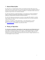
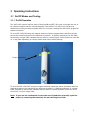
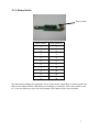
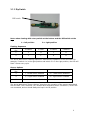
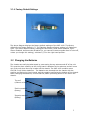
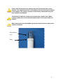
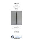
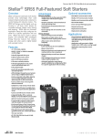
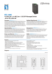
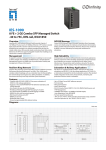
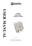
XMF-1000
LED Surface Flasher
User Manual
Version 1.0
June 2010
Xeos Technologies Inc.
2 Bluewater Rd.
Bedford, Nova Scotia, Canada
B4B 1G7
(902) 444-7650
www.xeostech.com
SHIPPED FROM:
Xeos Technologies Inc.
2 Bluewater Rd.
Bedford, Nova Scotia
Canada
B4B 1G7
How to contact us:
Email:
Phone:
Fax:
http://
[email protected]
902-444-7650
902-444-7651
www.xeostech.com
Contents
1
General Description............................................................................................. 1
2
Theory of Operation ............................................................................................ 1
3
Operating Instructions......................................................................................... 2
3.1
On/Off Modes and Testing ............................................................................. 2
3.1.1
On/Off Operation................................................................................... 2
3.1.2
Rotary Switch ....................................................................................... 3
3.1.3
DIP Switch............................................................................................ 4
3.1.4
Factory Default Settings ......................................................................... 5
3.2
Changing the Batteries ................................................................................. 5
Appendix A - Technical Specification .......................................................................... 7
1 General Description
The XMF-1000 is an independently powered, self contained surface flasher that is fully
submersible up to 1,000m (3,281 ft). The super-bright LED provides unparalleled visibility in
even the worst conditions and the reliability provided by our solid state surface sensor is a
significant improvement over mechanical methods.
The XMF-1000 features a miniaturized design in an all aluminum enclosure designed to
meet or exceed your operational requirements for a surface flasher. The XMF-1000 is
backed by a comprehensive warranty and excellent support.
The XMF-1000 features microprocessor controlled, ultra-bright LED available in multiple
colour options. The XMF-1000 has a long lasting operational life of 14 days and features
multiple activation options.
XMB-1000 is intended for surface deployments. Xeos Technologies Inc. (Xeos)
manufactures other specific products for surface and subsurface applications.
See www.xeostech.com for details or call (902) 444-7650.
2 Theory of Operation
The XMF-1000 is intended for locating and recovering high value, free drifting assets at sea
or as a general purpose search and rescue tool. After being activated, the XMF-1000 can
submerged (to a maximum depth of 1,000 meters). If the daylight off option is enabled,
the device will not flash during daytime. The XMF-1000 will continue to flash until it is
manually turned off, the battery pack drops below the minimum voltage requirement of 7v,
or if the daylight off option prohibits.
1
3 Operating Instructions
3.1 On/Off Modes and Testing
3.1.1 On/Off Operation
The XMF-1000 beacon has two ways of turning ON and OFF. One way is through the use of
an external magnet near an internal magnetic reed switch. The XMF-1000 can also be
disabled by turning the device upside-down for a minute. Holding the XMF-1000 upright will
enable the device.
To turn XMF-1000 ON using the magnet method, wipe the magnet back-and-forth quickly
across the area directly below the antenna connection. A flashing sequence of a dim flash,
followed by a bright flash indicates that the device is powering up. Once the device is turned
on, it will flash depending on the dip switch and rotary switch settings.
Swipe magnet here
To turn the XMF-1000 OFF using the magnet method, repeat the above procedure with the
magnet swiped on the area below the antenna connection. A flashing sequence of a bright
flash, followed by a dim flash indicates that the device is powering down. Once the unit is
turned off, it will no longer flash.
Note: If you use the reed switch to turn the unit off and then manually cycle the
power by removing the batteries, the unit will begin to flash.
2
3.1.2 Rotary Switch
Rotary switch
Switch Position
Delay (Seconds)
1
1
2
2
3
3
4
4
5
5
6
6
7
10
8
15
9
20
0
30
The table above displays the operation of the rotary switch. Depending on what number the
dial is set to delay between LED flashes will change. For example, if the rotary switch is set
to ‘3’ and one flash per cycle, the time between LED flashes will be three seconds.
3
3.1.3 Dip Switch
DIP switch
Note: when viewing with rotary switch at the bottom and the DIP switch at the
top:
L = left position
R = right position
Flashing Sequence
DIP Switch
0 Flashes
Pos
1 Flash
2 Flashes
3 Flashes
1
L
R
L
R
2
L
L
R
R
The above table titled “Flashing Sequence” describes the operation of the LED flash. For
example, if switch 1 is in the right position and switch 2 is in the right position, the LED will
flash 3 times every cycle.
Sensor Options
DIP Switch
Pos
3
L = Reed Switch Enabled
R = Reed Switch Disabled
4
L = Light Sensor Enabled
R = Light Sensor Disabled
5
L = Accelerometer Enabled
R = Accelerometer Disabled
The above table titled “Sensor Options” describes the operation of the sensors associated
with the XMF-7500. Switches 3,4,5 enable each respective sensor. Switches 6,7 and 8 are
not connected, and so should always be kept in the R position
4
3.1.4 Factory Default Settings
The above diagram displays the factory default settings of the XMF-1000. The factory
default for the Rotary Switch is ‘2’. The Flashing Sequence factory setting is 2 flashes per
cycle. The Sensor Options factory settings are as follows; Reed Switch Enabled, Light
Sensor Enabled, Accelerometer Disabled (ie. you cannot tilt device upside-down to shut off,
unless you change this setting), switches 6,7,8 in the right-hand position.
3.2 Changing the Batteries
The chassis can easily be taken apart by unscrewing the top antenna end off of the unit.
This must be done carefully as the circuit board is attached to the antenna, and will come
out of the unit when then top is taken off the chassis. The XMF-1000 contains seven
CR123A 3 volt lithium batteries. The batteries are inserted into the chassis with the
positive end facing the circuit board, and the negative end facing the bottom of the chassis.
When changing the batteries, ensure that the plastic protecting sleeve is still within the
chassis.
Top end
(connects to lens)
Positive terminal
(battery)
Negative terminal
(battery)
5
Ensure that all batteries are inserted into the chassis with the correct
polarity. The negative terminal of the battery should be facing the bottom
of the chassis. The positive terminal of the battery should be facing the
lens and the circuit board.
The batteries inside the chassis are protected by a plastic tube. When
replacing batteries, ensure that the plastic tube is still intact inside the
chassis.
When unscrewing the top ALWAYS grasp the top by the knurl and rotate
counter clockwise.
Polycarbonate
Lens
Knurl
6
Appendix A - Technical Specification
Mechanical:
Material:
Chassis: Aluminum 6061
Paint: Marine Grade Powdercoat
Lens: Polycarbonate
Dimensions:
37 cm L x 2.6 cm W (14.5” L x 1.05” W)
Weight:
Out of water: 397g
In water:
252g
O-rings:
568-019 70A DURO BUNA
O-Ring Lube:
Parker Super ‘O’
7
Electrical:
Power Supply
Internal Battery Supply:
Voltage:
Capacity:
Life expectancy:
7x CR123A 3 volt lithium batteries
+21 volts nominal
20 Amp-hours
14 days, double burst every 4 seconds while in daylight off
Approx. 60 days, single burst every 10 seconds while in
daylight off
Electronics
Digital Controller:
ON/OFF Controls:
Pulse Options:
LED:
Luminous Flux:
Xeos LED Flasher
Switch on board (for storage and shipping)
Reed Switch for activating without opening the case
Solid State tilt switch for upright activation and deactivation
1,2 or 3 flashes/cycle
3.9W, single emitter type
White – 70 lumens (70lm)
Amber – 100 lumens (100lm)
Environmental
Operating Temperature:
Depth Rating:
-40° C to +60° C (-40° F to +140° F)
Submersible to 1,000m (3,281ft)
8
Warranty, Support and Limited Liability
Xeos Technologies Inc. warranties the XMF-1000 to be free of defects in material or
manufacturing for a period of one year following delivery. Liability is limited to repair or
replacement of the defective part and will be done free of charge.
LIMITED WARRANTY: Xeos Technologies Inc. warrants that the product will perform
substantially in accordance with the accompanying written materials for a period of
one year from the date of receipt.
CUSTOMER REMEDIES: Xeos Technologies Inc. entire liability and your exclusive remedy
shall be at Xeos Technologies Inc. option, either (a) return of the price paid or (b) repair or
replacement of the product that does not meet Xeos Technologies Inc. Limited Warranty
and that is returned to Xeos Technologies Inc. with a copy of your receipt. This Limited
Warranty is void if failure of the product has resulted from accident, abuse, or
misapplication. Any replacement product will be warranted for the remainder of
the original warranty period or ninety (90) days, whichever is longer.
NO OTHER WARRANTIES: Xeos Technologies Inc. disclaims all other warranties, either
express or implied, including but not limited to implied warranties of merchantability and
fitness for a particular purpose, with respect to the product or the accompanying written
materials. This limited warranty gives you specific legal rights. You may have others,
which vary from state to state.
NO LIABILITY FOR CONSEQUENTIAL DAMAGES: In no event shall Xeos Technologies Inc. or
its suppliers be liable for any damages whatsoever (including, without limitation, damages
for loss of equipment, for loss of business profits, business interruption, loss of business
information, or other pecuniary loss) arising out of the use of or inability to use this
Xeos Technologies Inc. product, even if Xeos Technologies Inc. has been advised of the
possibility of such damages.
9