1
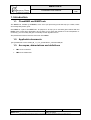
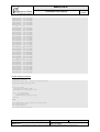
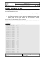
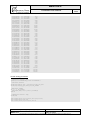
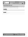
BMGTOOLS
PAGE
CheckBMG User Manual
1/35
Deliverable D1
User Manual
CheckBMG
Name
Date
Prepared by
Benoît Thiébault
14/12/2010
Verified by
Jérémie Turbet
15/12/2010
Julien Forest
16/12/2010
Approved by
Reference: IFR_BMGV3_D1B_Check_User_Manual
Version: 3
Status: Final
Date: 16/12/2010
Signature
Revision: 0
This document is the property of Artenum. It cannot be used, copied or distributed without prior written approval.
BMGTOOLS
PAGE
CheckBMG User Manual
2/35
Presentation
The objective of this document is to provide the user of CheckBMG the relevant information to
understand how to install, launch and use the application.
Technical content summary
This document is divided in two main parts:
-
The prerequisites detail the hardware and software requirements to run the application,
explains how to install and launch the application.
-
The second part explains how to use the application and details its main functions.
Diffusion
Name
Organisation
Julien Forest
Benoît Thiébault
Jérémie Turbet
Artenum
Sébastien Theetten
Fabrice Lecornu
Jean-François Le Roux
Franck Dumas
Pascal Douillet
IFREMER
Changes
Version
Revision
Date
Auteur / Observation
1
1
15/04/2009 Benoît Thiébault / Document creation
1
2
20/10/2009 Benoît Thiébault / Update to take into account version 2.0 Alpha
1
3
16/12/2009 Benoît Thiébault / Update to take into account version 2.0 Bêta
2
0
24/02/2010 Benoît Thiébault / Update to take into account version 2.0
3
0
16/12/2010 Benoît Thiébault / Update to take into account version 3.0.0-alpha
Reference: IFR_BMGV3_D1B_Check_User_Manual
Version: 3
Status: Final
Date: 16/12/2010
Revision: 0
This document is the property of Artenum. It cannot be used, copied or distributed without prior written approval.
BMGTOOLS
PAGE
CheckBMG User Manual
3/35
Table of contents
1. INTRODUCTION ................................................................................ 5 1.1. CheckBMG and BMGTools ................................................................... 5 1.2. Applicable documents .......................................................................... 5 1.3. Acronyms, abbreviations and definitions ........................................... 5 2. PREREQUISITES .............................................................................. 6 2.1. Configuration ......................................................................................... 6 2.1.1. Hardware requirements ................................................................................... 6 2.1.2. Software requirements ..................................................................................... 6 2.2. Installation .............................................................................................. 6 2.3. Running the application ........................................................................ 6 3. USING THE APPLICATION .............................................................. 7 3.1. User interface ......................................................................................... 7 3.1.1. Overview .......................................................................................................... 7 3.1.2. Menu bar .......................................................................................................... 7 3.1.3. Map viewer ....................................................................................................... 8 3.1.4. Layers view .................................................................................................... 10 3.1.5. Grid display modes and depth values ............................................................ 11 3.1.6. Status bar ....................................................................................................... 15 3.1. Opening an existing file ...................................................................... 15 3.2. Saving the grid file .............................................................................. 17 3.3. Closing the grid file ............................................................................. 17 3.4. Setting up the preferences ................................................................. 17 3.5. Exiting the application ........................................................................ 21 3.6. Manipulating the map .......................................................................... 21 3.7. Editing grid points ............................................................................... 21 3.8. Editing river positions ......................................................................... 23 3.9. Viewing the grid in 3D ......................................................................... 24 3.10. Undoing an action ............................................................................. 24 ANNEX A BATHYMETRIC GRID FILE ....................................... 26 ANNEX B COASTLINE FILE .LINE ............................................ 29 Reference: IFR_BMGV3_D1B_Check_User_Manual
Version: 3
Status: Final
Date: 16/12/2010
Revision: 0
This document is the property of Artenum. It cannot be used, copied or distributed without prior written approval.
BMGTOOLS
PAGE
CheckBMG User Manual
4/35
ANNEX C SOUNDINGS FILE .SDG ............................................ 32 ANNEX D RIVERS FILE .RIVER ................................................. 34 ANNEX E COLOUR BAR FILE FORMAT ................................... 35 Reference: IFR_BMGV3_D1B_Check_User_Manual
Version: 3
Status: Final
Date: 16/12/2010
Revision: 0
This document is the property of Artenum. It cannot be used, copied or distributed without prior written approval.
BMGTOOLS
PAGE
CheckBMG User Manual
5/35
1. Introduction
1.1. CheckBMG and BMGTools
The BMGTools, created by IFREMER, are a set of pre-processing tools that help you create, check
and modify bathymetric grids.
CheckBMG is a part of the BMGTools. Its purpose is to help you to visualise grids created with the
MARS code or with other applications and to allow you to check the relevance of the interpolation. If
necessary, you can modify the grid to manually correct algorithm errors.
The present document is the user manual of CheckBMG.
1.2. Applicable documents
[DA1] Statement of work: 2008_08_11_v14_specifications_creaverimaille.pdf
1.3. Acronyms, abbreviations and definitions
•
TBC: to be confirmed
•
TBD: to be determined
Reference: IFR_BMGV3_D1B_Check_User_Manual
Version: 3
Status: Final
Date: 16/12/2010
Revision: 0
This document is the property of Artenum. It cannot be used, copied or distributed without prior written approval.
BMGTOOLS
PAGE
CheckBMG User Manual
6/35
2. Prerequisites
2.1. Configuration
2.1.1. Hardware requirements
The minimal hardware configuration to properly run the BMG Tools is:
-
Intel/AMD x86 32/64bit processor, with a frequency higher than
1.7GHz (Intel Core 2 Duo T7700 at 2.4 GHz recommended)
-
1Gb of RAM (2Gb recommended, especially for large grids)
-
Graphic card with more than 128Mb of video memory (NVIDIA Quadro
FX 570M or equivalent recommended)
-
Screen resolution
recommended)
-
100Mb of free space on the hard drive
of
1024x768
pixels
(1280x1024
resolution
2.1.2. Software requirements
The BMG Tools have been tested to work under Windows XP SP3 and Linux
Fedora Core 8. It requires SUN Java 6 or higher installed (cf.
http://www.java.com for the latest version download).
2.2. Installation
The application should be provided in a compressed archive (.zip or .gz for
instance). Simply uncompress the archive to the desired location of your hard
drive.
The folder obtained after decompression is illustrated on Figure 1.
2.3. Running the application
In the check folder, there are two executable files. Under Windows, these are:
-
CheckBMG.bat, a DOS batch command that can be launched by
double-clicking it;
-
ProfileCheckBMG.bat, a DOS batch command that can be launched
by double-clicking it;
On Linux machines the executable files are:
-
CheckBMG.sh, the shell script command that can be executed via
command line;
Figure 1: Application folder
ProfileCheckBMG.sh, the shell script command that can be executed
via command line;
The profile command is present for test purpose only. It logs in the terminal the different times to
execute some key functions (like refreshing the user interface).
For users who want to create grid with the tools, the CheckBMG command is sufficient.
Reference: IFR_BMGV3_D1B_Check_User_Manual
Version: 3
Status: Final
Date: 16/12/2010
Revision: 0
This document is the property of Artenum. It cannot be used, copied or distributed without prior written approval.
BMGTOOLS
PAGE
CheckBMG User Manual
7/35
3. Using the application
3.1. User interface
3.1.1. Overview
When the application is first opened, the window displayed in Figure 2 appears on the screen. It is
divided in 5 main parts:
1) The menu bar gives you access to some of the application main functions. It is composed of
five menu items, File, Views, History, Tools and Help and of a tool bar containing buttons for
actions that are frequently used.
2) The map tool bar allows you to select the different tools available for you to interact with the
data and its representation. When you perform a copy/paste action, the copied value appears
on the right part of this tool bar.
3) The layers view shows the layers that have been loaded by the user. Layers on top of this
layer view are drawn on top in the map view.
4) The map view allows you to interact with the map representation of the data.
5) The status bar gives you information about the projection system and the mouse cursor
position on the map.
Figure 2: Interface overview
3.1.2. Menu bar
The menu bar (cf. Figure 3) contains four menu items and a tool bar:
Reference: IFR_BMGV3_D1B_Check_User_Manual
Version: 3
Status: Final
Date: 16/12/2010
Revision: 0
This document is the property of Artenum. It cannot be used, copied or distributed without prior written approval.
BMGTOOLS
PAGE
CheckBMG User Manual
-
8/35
The File menu contains the application main operations:
o
Open grid file to open an existing grid file and the associated coastlines and
soundings
o
Close grid file to close the current grid file
o
Save grid file to save the current grid file
o
Save grid as… to save the current grid file under a different name
o
Export to save the map either in PNG or EPS format. Beware that the EPS format is a
vector representation of the image. This means that every graphic element displayed
on the screen is saved as a vector object in the file. This has the advantage of
providing a file that can be indefinitely zoomed in without loss of quality. The
counterpart is that for maps containing a lot of elements (such as soundings points for
instance), the EPS file can quickly become huge and hard to manipulate. In that case,
prefer the use of the PNG bitmap format.
o
Preferences to access the application settings
o
Quit to exit the application
-
The Views menu contains the list of views that the user can open and close.
-
The History menu contains the list of your last actions that can be undone.
-
The Tools menu contains extra functions, like the 3D view of the map. This action can only be
performed if VTK is properly installed (i.e. on target platforms) and if a grid is loaded.
-
The Help menu gives access to the About dialog, displaying general information about the
application.
-
The tool bar provides shortcuts for the following menu functions:
o
Open grid file
o
Save grid file
o
Preferences
Some of the menu items and tool bar buttons are deactivated by default. They activate automatically
when necessary.
Figure 3: Menu bar
3.1.3. Map viewer
The map viewer (cf. Figure 5) is composed of the map, the colour bar scale and the tool bar:
-
The map itself displays loaded information, such as grids, coastlines, soundings, etc. In order
to keep the rendering quick and efficient, a Level Of Detail (LOD) algorithm, which only
displays a part of the real data, is automatically applied when the data is seen from far away.
When this algorithm is activated, a LOD icon is displayed on the top left corner of the map (cf.
Reference: IFR_BMGV3_D1B_Check_User_Manual
Version: 3
Status: Final
Date: 16/12/2010
Revision: 0
This document is the property of Artenum. It cannot be used, copied or distributed without prior written approval.
BMGTOOLS
PAGE
CheckBMG User Manual
9/35
Figure 4). The level of the algorithm is also displayed. The higher the level, the more data is
hidden.
Figure 4: Level Of Detail warning icon and algorithm level
-
The tool bar allows you to interact with the map. It is composed of one isolated button on the
left and of a toggle buttons bar. The isolated button at the left resets the view to the initial map
zoom when pressed. The toggle buttons bar contains several buttons. One and only one
button of this tool bar is always selected. Depending on which button is selected, the main
mouse action on the map have different effects (the main action can attributed to any of the
mouse buttons, as seen in 3.4):
o
The Move button, on the left, lets you move the map
o
The Zoom in button allows you to zoom in the map by either clicking a place on the
map or selecting a zoom zone with a mouse drag and drop action.
o
The Zoom out button allows you to zoom out the map by either clicking a place on the
map or selecting a zoom zone with a mouse drag and drop action.
o
The Edit grid points button offers the possibility to edit the grid points one by one,
sequentially, by selecting a rectangular or a polygonal zone (cf. 3.7 for more details).
o
The Save grid points button allows you to save in a text file the grid points that have
been selected either sequentially or by selecting a rectangular or a polygonal zone.
Whatever the selected tool, you can zoom in or out the map with the mouse wheel.
-
The Copied value text field shows the depth value (in meters) that is stored in memory and
will be applied if you perform a Paste action on the grid.
-
The colour bar scale is displayed at the bottom of the map and shows you the colour / depth
value correspondence. It can be edited by clicking the Edit color bar button, similarly as in
the Preferences panel (cf. 3.4). The only difference is the Apply changes button that directly
applies the colour bar modifications to the data displayed. The edition dialog is not modal,
which means you can still interact with the map even if this dialog is not closed.
Reference: IFR_BMGV3_D1B_Check_User_Manual
Version: 3
Status: Final
Date: 16/12/2010
Revision: 0
This document is the property of Artenum. It cannot be used, copied or distributed without prior written approval.
BMGTOOLS
PAGE
CheckBMG User Manual
10/35
Figure 5: Map viewer
3.1.4. Layers view
The layers view illustrated on Figure 6, show all the layers currently loaded in the application and
shown on the map viewer. The check box at the right side of each layer can be used to display or hide
the corresponding layer.
The “+” and “-“ buttons at the top right can be used to dynamically add or remove layers.
Figure 6: Layers view
Reference: IFR_BMGV3_D1B_Check_User_Manual
Version: 3
Status: Final
Date: 16/12/2010
Revision: 0
This document is the property of Artenum. It cannot be used, copied or distributed without prior written approval.
BMGTOOLS
PAGE
CheckBMG User Manual
11/35
3.1.5. Grid display modes and depth values
There are two grid display modes in CheckBMG: Hx/Hy mode and H0 mode.
When the Hx/Hy mode is selected (cf. Figure 7), only the cell bounds are displayed on the map. The
vertical segments correspond to Hx while the horizontal segments correspond to Hy. Each segment
has a different depth and can be modified independently.
Figure 7: Map in Hx/Hy mode
When the H0 mode is selected (cf. Figure 8), the cells are fully painted, representing the H0 depth.
Reference: IFR_BMGV3_D1B_Check_User_Manual
Version: 3
Status: Final
Date: 16/12/2010
Revision: 0
This document is the property of Artenum. It cannot be used, copied or distributed without prior written approval.
BMGTOOLS
PAGE
CheckBMG User Manual
12/35
Figure 8: Map in H0 mode
Whatever the display mode, you can see the exact depth value of the displayed grid elements by
selecting the Grid text values item in the Layers view as illustrated on Figure 9 and Figure 10.
Reference: IFR_BMGV3_D1B_Check_User_Manual
Version: 3
Status: Final
Date: 16/12/2010
Revision: 0
This document is the property of Artenum. It cannot be used, copied or distributed without prior written approval.
BMGTOOLS
PAGE
CheckBMG User Manual
13/35
Figure 9: Grid depth values in Hx/Hy display mode
Figure 10: Grid depth values in H0 display mode
Reference: IFR_BMGV3_D1B_Check_User_Manual
Version: 3
Status: Final
Date: 16/12/2010
Revision: 0
This document is the property of Artenum. It cannot be used, copied or distributed without prior written approval.
BMGTOOLS
PAGE
CheckBMG User Manual
14/35
You can as well visualise soundings depth values by selecting the Soundings text values item in the
Layers view as illustrated on Figure 11. The soundings text values are displayed as a 45 degrees
rotated text on the map so that they are not misinterpreted as grid text values. This rotation angle can
be configured, as explained in 3.4.
Figure 11: Soundings depth values
When selecting the Isobaths values in the Layers view, the associated depth is drawn along the
corresponding isobath line, as shown on Figure 12.
Reference: IFR_BMGV3_D1B_Check_User_Manual
Version: 3
Status: Final
Date: 16/12/2010
Revision: 0
This document is the property of Artenum. It cannot be used, copied or distributed without prior written approval.
BMGTOOLS
PAGE
CheckBMG User Manual
15/35
Figure 12: Isobaths depth values
3.1.6. Status bar
The status bar (cf. Figure 13) displays two kinds of information:
-
On the left, the projection system in which the data is drawn on the map is displayed
-
On the right, the mouse cursor coordinates on the map are given either in geographic
coordinates (degrees), in projected coordinates (meters) or in grid indexes. The depth of the
nearest grid point element is also displayed here.
Figure 13: Status bar
3.1. Opening an existing file
To open an existing grid file, you have to click the File>Open grid file menu item or to select the
Open grid file shortcut button.
You will then be asked to select the files to load (cf. Figure 14).
Reference: IFR_BMGV3_D1B_Check_User_Manual
Version: 3
Status: Final
Date: 16/12/2010
Revision: 0
This document is the property of Artenum. It cannot be used, copied or distributed without prior written approval.
BMGTOOLS
PAGE
CheckBMG User Manual
16/35
Figure 14: Open MARS grid file dialog
By default, the grid file to provide is a NetCDF file generated by MARS. This file format is described in
Annex A. If you want to proceed using the software, this is the only file you can provide. The geodetic
and projection systems are automatically chosen by the application if they are indicated in the grid file.
You can choose a different projection system in the drop down menu. If the geodetic system is not
described in the grid file, you have to select it in the drop down menu.
If you wish to load files created with NEMO (http://www.nemo-ocean.eu/), you can choose the NEMO
file format is the drop down menu, as illustrated in Figure 15.
Figure 15: Open NEMO grid files (coordinates and bathymetry)
Reference: IFR_BMGV3_D1B_Check_User_Manual
Version: 3
Status: Final
Date: 16/12/2010
Revision: 0
This document is the property of Artenum. It cannot be used, copied or distributed without prior written approval.
BMGTOOLS
PAGE
CheckBMG User Manual
17/35
In this case, you have to provide two different files: a coordinates file, then the corresponding
bathymetry file. When viewing a NEMO grid file, only the H0 display mode is available.
There is then a set of optional files that you can provide if you wish to visualise other data.
You can provide a “coastlines file”, containing coastlines and/or isobaths data. This file can be
provided either in the .line format, described in Annex B or in the Shapefile format. The Shapefile
format is however only partially supported for files coming from the SHOM or SEXTANT database.
You can provide as well a soundings file, whose format is described in Annex C. This file is optional.
Finally, you can provide an optional river file, whose format is described in Annex D.
To validate your choice, you have to click the OK button. The selected files are then loaded and
displayed on the map. As the soundings file can be very heavy (more than 2 million soundings for
instance), it is not displayed on the map by default to accelerate the map drawing process. The file is
however loaded in background. As soon as it is fully loaded and ready to be displayed, the two
corresponding items are added in the Layers view (one item to display the soundings, another to
display the text values).
3.2. Saving the grid file
If you have modified the grid, you can choose to save the file by selecting the File>Save grid file
menu item or by clicking the save grid file shortcut button.
You can only save the grid file when a modification has been made. At anytime, however, you can
choose the File>Save grid as… menu item to save the grid file with a different name or at a different
location.
3.3. Closing the grid file
To close an opened grid file, you have to select the File>Close grid file menu item.
If the grid file has been modified, you will be proposed to save the grid file first.
3.4. Setting up the preferences
To edit the application preferences, you can select the File>Preferences… menu item or to click the
preferences shortcut button.
The preferences window is separated in two tabs:
-
The General tab (cf. Figure 16) contains preferences common throughout the BMGTools.
You can here change the interface language (requires to restart the application to be
effective), change the different coastline file elements colour and set the colour gradient
associated with the isobaths depth (see below for more details).
Reference: IFR_BMGV3_D1B_Check_User_Manual
Version: 3
Status: Final
Date: 16/12/2010
Revision: 0
This document is the property of Artenum. It cannot be used, copied or distributed without prior written approval.
BMGTOOLS
PAGE
CheckBMG User Manual
18/35
Figure 16: General preferences
If you want to edit one of the colour bars available, you have to select the colour bar and click the Edit
color bar button that shows the Edit color bar window (cf. Figure 17). There are three colour bars
provided by default. These default colour bar cannot be deleted or overridden, so if you wish to modify
them, you will have to change their name in the Edit color bar window. You can also import an
existing colour bar by using the Load… button. The file format for colour bar files is described in
Annex E.
In the Edit color bar window, you can add new colours in the colour bar or delete existing ones.
To add a new colour, click the coloured button next to the Color text. A dialog will let you choose the
colour you want to add. After choosing a colour, input a colour position in the colour bar. The colour
bar contains a configurable number of colours (say nbColours). The position of the new colour has to
be between 1 and nbColours – 2 (as the starting and ending colours are at positions 0 and nbColours
– 1). Then click the Add color button.
To remove a colour, simply select the thumb representing it and click the Delete color button.
You can also change colours position in the gradient by dragging the colourʼs thumb, change the total
number of colours in the colour bar and choose an automatic range (that will be adapted to the data
scalar range when data is loaded) or force a given one.
Reference: IFR_BMGV3_D1B_Check_User_Manual
Version: 3
Status: Final
Date: 16/12/2010
Revision: 0
This document is the property of Artenum. It cannot be used, copied or distributed without prior written approval.
BMGTOOLS
PAGE
CheckBMG User Manual
19/35
Figure 17: Edit gradient window
-
The CheckBMG preferences tab (cf. Figure 18) contains preferences specific to this
application. You can choose the colour of the selected grid elements, of the elements with
ground values, the font characteristics of the text values and other graphic elements settings.
This is also where you can configure the buttons of your mouse and attribute to each of them
a specific action. There are four configurable actions available:
o
Main action: this is the action that is performed according to the selected button in the
tool bar (to move the map, zoom in or out, edit the grid points, etc.).
o
Copy: allows you to copy the value of the nearest grid element
o
Paste: pastes the copied value (displayed in the tool bar) to the nearest grid point.
o
Contextual menu: shows a contextual menu (cf. Figure 19) allowing you to copy,
paste a grid element.
You can go back to default settings by pressing the default button.
Reference: IFR_BMGV3_D1B_Check_User_Manual
Version: 3
Status: Final
Date: 16/12/2010
Revision: 0
This document is the property of Artenum. It cannot be used, copied or distributed without prior written approval.
BMGTOOLS
PAGE
CheckBMG User Manual
20/35
Figure 18: CheckBMG preferences
Figure 19: Contextual menu
Reference: IFR_BMGV3_D1B_Check_User_Manual
Version: 3
Status: Final
Date: 16/12/2010
Revision: 0
This document is the property of Artenum. It cannot be used, copied or distributed without prior written approval.
BMGTOOLS
PAGE
CheckBMG User Manual
21/35
3.5. Exiting the application
To close the application, you have to select the File>Quit menu.
If the grid file has been modified, you will be proposed to save the grid file.
3.6. Manipulating the map
The navigation map tool bar (cf. Figure 20) allows you to manipulate the map. The initial zoom button
on the left of the tool bar resets the zoom level to the initial one when pressed.
The Move button lets you move the map.
The Zoom in button allows you to zoom in the map by either clicking a place on the map or selecting a
zoom zone with a mouse drag and drop action on the map.
The Zoom out button allows you to zoom out the map by either clicking a place on the map or
selecting a zoom zone with a mouse drag and drop action on the map.
You can as well use the mouse wheel to zoom in or out in the map.
Figure 20: Navigation map tool bar
3.7. Editing grid points
The Edit grid points button (cf. Figure 21) allows you to edit grid points.
Figure 21: New grid button
Once selected, you can choose the edition mode in a drop-down menu:
-
Single point mode lets you modify the grid elements one by one;
-
In Sequential mode, you can select several grid elements in a row, then press Return to
change the values (cf. Figure 22);
Reference: IFR_BMGV3_D1B_Check_User_Manual
Version: 3
Status: Final
Date: 16/12/2010
Revision: 0
This document is the property of Artenum. It cannot be used, copied or distributed without prior written approval.
BMGTOOLS
PAGE
CheckBMG User Manual
22/35
Figure 22: Sequential edition mode
-
In Rectangle mode, you can select all grid elements contained in the rectangle he draws by a
“drag and drop” action of the mouse on the map (cf. Figure 23);
Figure 23: Rectangle edition mode
-
In Polygon mode, you can select all grid elements contained in the polygon you draw on the
map by clicking several times on the polygon vertices. To finish the polygon, you have to click
on the first point again (cf. Figure 24);
Figure 24: Polygon edition mode
Reference: IFR_BMGV3_D1B_Check_User_Manual
Version: 3
Status: Final
Date: 16/12/2010
Revision: 0
This document is the property of Artenum. It cannot be used, copied or distributed without prior written approval.
BMGTOOLS
PAGE
CheckBMG User Manual
23/35
You can also edit the grid point with the copy and paste functions or the contextual menu that you
have configured in the preferences (see 3.4).
The Save grid points button (cf. Figure 25) allows you to save in a file the selected grid points
without modifying them. It works the same way as the Edit grid points button except that there is no
Single point selection mode.
Figure 25: Tool to save selected grid elements to file
3.8. Editing river positions
Rivers can be drawn on the map as shown on Figure 26.
Figure 26: Rivers drawn on the map
The Edit river position button (cf. Figure 27) allows you to move the river positions on the grid.
Simply drag the river positions. You web e asked if you want to update the river file.
Reference: IFR_BMGV3_D1B_Check_User_Manual
Version: 3
Status: Final
Date: 16/12/2010
Revision: 0
This document is the property of Artenum. It cannot be used, copied or distributed without prior written approval.
BMGTOOLS
PAGE
CheckBMG User Manual
24/35
Figure 27: Edit river position button
3.9. Viewing the grid in 3D
On supported platforms, you can view the grid in three dimensions. Simply go to the Tools>3D View
menu once you have loaded a map to display the 3D window shown on Figure 28. You can then
move the map with the mouse left and right buttons and zoom in or out with the mouse wheel.
You can set the depth scale with the provided slider, choose the display mode, reset the view or save
it as a PNG image.
Beware that is the land value of your grid is set to a very low value (say -999 999 meters), the 3D view
will not provide an pertinent result. Moreover, be aware that for large grids (more than 1000x1000 grid
elements), the rendering may be long and require a lot of memory.
Figure 28: 3D view of the grid
3.10. Undoing an action
The user can undo some of the actions he performed. To do so, the user has to go in the History
menu (cf. Figure 29) and select the last undoable action.
Reference: IFR_BMGV3_D1B_Check_User_Manual
Version: 3
Status: Final
Date: 16/12/2010
Revision: 0
This document is the property of Artenum. It cannot be used, copied or distributed without prior written approval.
BMGTOOLS
PAGE
CheckBMG User Manual
25/35
Figure 29: History menu
Reference: IFR_BMGV3_D1B_Check_User_Manual
Version: 3
Status: Final
Date: 16/12/2010
Revision: 0
This document is the property of Artenum. It cannot be used, copied or distributed without prior written approval.
BMGTOOLS
PAGE
CheckBMG User Manual
26/35
Annex A Bathymetric grid file
A bathymetric grid file is a NetCDF file, which name ends with the .nc extension. The file has to follow
the NetCDF format below:
// dimensions:
ni = xxx ;
nj = xxx ;
// variables:
float H0(nj, ni) ;
H0:long_name = "bathymetrie par rapport a REF_ZERO" ;
H0:units = "m" ;
H0:standard_name = "sea_floor_depth_below_REF_ZERO" ;
H0:standard_name = "sea_floor_depth_below_sea_level ;
H0:_FillValue = xxx ;
H0:valid_min = xxx ;
H0:valid_max = xxx ;
H0:coordinates = "longitude latitude"
float HX(nj, ni) ;
HX:long_name = "bathymetrie hx par rapport a REF_ZERO" ;
HX:units = "m" ;
HX:standard_name = "sea_floor_depth_below_REF_ZERO" ;
HX:standard_name = "sea_floor_depth_below_sea_level ;
HX:_FillValue = xxx ;
HX:valid_min = xxx ;
HX:valid_max = xxx ;
HX:coordinates = "longitude_U latitude"
float HY(nj, ni) ;
HY:long_name = "bathymetrie hy par rapport a REF_ZERO" ;
HY:units = "m" ;
HY:standard_name = "sea_floor_depth_below_REF_ZERO" ;
HX:standard_name = "sea_floor_depth_below_sea_level ;
HY:_FillValue = xxx ;
HY:valid_min = xxx ;
HY:valid_max = xxx ;
HY:coordinates = "longitude latitude_V"
float niv_moy(nj, ni) ;
HY:long_name = "niveau moyen" ;
HY:units = "m" ;
HY:standard_name = "???" ;
HY:_FillValue = xxx ;
HY:valid_min = xxx ;
HY:valid_max = xxx ;
HY:coordinates = "longitude latitude"
float ni(ni) ;
ni:long_name = "x-coordinate" ;
ni:axis = "X" ;
float nj(nj) ;
nj:long_name = "y-coordinate" ;
nj:axis = "Y" ;
double longitude(nj,ni) ;
lon:long_name = "longitude" ;
lon:standard_name = "longitude" ;
lon:units = "degree_east" ;
lon:valid_min = xxx ;
lon:valid_max = xxx ;
lon:_FillValue = xxx ;
double latitude(nj,ni) ;
lat:long_name = "latitude" ;
lat:standard_name = "latitude" ;
lat:units = "degree_north" ;
lat:valid_min = xxx ;
lat:valid_max = xxx ;
lat:_FillValue = xxx ;
double longitude_U(nj,ni) ;
lon:long_name = "longitude of U-points" ;
lon:standard_name = "longitude" ;
lon:units = "degree_east" ;
lon:valid_min = xxx ;
Reference: IFR_BMGV3_D1B_Check_User_Manual
Version: 3
Status: Final
Date: 16/12/2010
Revision: 0
This document is the property of Artenum. It cannot be used, copied or distributed without prior written approval.
BMGTOOLS
PAGE
CheckBMG User Manual
27/35
lon:valid_max = xxx ;
lon:_FillValue = xxx ;
double latitude_U(nj,ni) ;
lat:long_name = "latitude of U-points" ;
lat:standard_name = "latitude" ;
lat:units = "degree_north" ;
lat:valid_min = xxx ;
lat:valid_max = xxx ;
lat:_FillValue = xxx ;
double longitude_V(nj,ni) ;
lon:long_name = "longitude of V-points" ;
lon:standard_name = "longitude" ;
lon:units = "degree_east" ;
lon:valid_min = xxx ;
lon:valid_max = xxx ;
lon:_FillValue = xxx ;
double latitude_V(nj,ni) ;
lat:long_name = "latitude of V-points" ;
lat:standard_name = "latitude" ;
lat:units = "degree_north" ;
lat:valid_min = xxx ;
lat:valid_max = xxx ;
lat:_FillValue = xxx ;
double longitude_F(nj,ni) ;
lon:long_name = "longitude of F-points" ;
lon:standard_name = "longitude" ;
lon:units = "degree_east" ;
lon:valid_min = xxx ;
lon:valid_max = xxx ;
lon:_FillValue = xxx ;
double latitude_F(nj,ni) ;
lat:long_name = "latitude of F-points" ;
lat:standard_name = "latitude" ;
lat:units = "degree_north" ;
lat:valid_min = xxx ;
lat:valid_max = xxx ;
lat:_FillValue = xxx ;
// global attributes:
:geodetic_system = "GEO_SYS_WKT_FORMAT" ;
:geodetic_system_short = "GEO_SYS" ;
:grid_creation_mode = "GEOGRAPHIC_COORDINATES" ;
:data_type = "OCO oriented grid" ;
:format_version = "1.2" ;
:Conventions = "CF-1.3" ;
:netcdf_version = "3.6.3" ;
:product_version = "1.0" ;
:software_version = "X.X" ;
:references = "http://www.previmer.org/" ;
:easting = "longitude" ;
:northing = "latitude" ;
:grid_projection = "PROJECTION_SYSTEM_WKT_FORMAT" ;
:grid_projection_short = "n/a" ;
:institution = "IFREMER" ;
:institution_references = "http://www.ifremer.fr/" ;
:contact = "[email protected]" ;
:title = "bathymetrie Golfe du Lion" ;
:product_name = "/export/home10/res/bathy_gdl.nc" ;
:creation_date = "2008-10-24T22:34:32Z" ;
:comment = "Arakawa C grid" ;
:source = "CREAMAILLE V6.26" ;
:area = "GOLFE DU LION" ;
:southernmost_latitude = "XX.XXXX" ;
:northernmost_latitude = "XX.XXXX" ;
:latitude_resolution = "X.XXXX" ;
(il s'agit du dPhi)
:projected_latitude_resolution = "XXXXX.X" ; (il s'agit du dY)
:westernmost_longitude = "-X.XXXX" ;
:easternmost_longitude = "X.XXXX" ;
:longitude_resolution = "X.XXXX" ;
(il s'agit du dg)
:projected_longitude_resolution = "XXXXX.X" ;
(il s'agit du dX)
:minimum_altitude = "0.0 m" ;
:maximum_altitude = "0.0 m" ;
Reference: IFR_BMGV3_D1B_Check_User_Manual
Version: 3
Status: Final
Date: 16/12/2010
Revision: 0
This document is the property of Artenum. It cannot be used, copied or distributed without prior written approval.
BMGTOOLS
PAGE
CheckBMG User Manual
28/35
:altitude_resolution = "n/a" ;
:field_type = "permanent" ;
:distribution_statement = "Approved for public release. Distribution unlimited"
;
:operational_status = "operational" ;
:quality_index = "1" ;
:rotation_angle = "XX" ;
:latitude_rotation_center = "XX.XXXX" ;
:longitude_rotation_center = "XX.XXXX" ;
Reference: IFR_BMGV3_D1B_Check_User_Manual
Version: 3
Status: Final
Date: 16/12/2010
Revision: 0
This document is the property of Artenum. It cannot be used, copied or distributed without prior written approval.
BMGTOOLS
PAGE
CheckBMG User Manual
29/35
Annex B Coastline file .line
The coastline file is an ASCII file which name ends with the .line extension. It contains the definition of
the coastlines, the isobaths, the reefs and fringing reefs.
The file starts with a two lines header:
•
The first line is composed of four spaces separated floats defining the geographical
boundaries of the area described by the file: longitude_min longitude_max latitude_min
latitude_max
•
The second line is composed of a string and an integer indicating respectively the geodetic
reference system and the number of coastlines, isobaths and/o reefs: geodetic_system_name
polylines_number.
The body of the file is then composed of blocks. There are as many blocks as polylines number.
Each block starts with a one-line header indicating the number of points composing the polyline and a
code describing the line type. The code is an number taking the following values:
•
0 for coastlines
•
Any positive value for isobaths
•
A negative value (-1 or -2) for reefs
.line sample file:
165.33000000 167.50000000
WGS84
9
16
50
166.50180000 -22.49082000
166.47880000 -22.50999000
166.47970000 -22.51010000
166.48050000 -22.51051000
166.48120000 -22.51100000
166.48190000 -22.51141000
166.48270000 -22.51155000
166.48340000 -22.51152000
166.48410000 -22.51137000
166.48490000 -22.51107000
166.48570000 -22.51067000
166.48660000 -22.50985000
166.48700000
22.50921000
166.48720000 -22.50843000
166.48740000 -22.50751000
166.48750000 -22.50663000
14
40
166.43440000 -22.49340000
166.43500000
22.49416000
166.43560000 -22.49497000
166.43620000 -22.49562000
166.43690000 -22.49644000
166.43750000 -22.49734000
166.43790000 -22.49813000
166.43820000 -22.49858000
166.43890000 -22.49874000
166.43960000 -22.49858000
166.44060000 -22.49823000
166.44140000 -22.49783000
166.44230000 -22.49744000
166.44320000 -22.49701000
22
30
166.57450000 -22.38101000
166.57490000 -22.38060000
-23.10000000
-21.41000000
Reference: IFR_BMGV3_D1B_Check_User_Manual
Version: 3
Status: Final
Date: 16/12/2010
Revision: 0
This document is the property of Artenum. It cannot be used, copied or distributed without prior written approval.
BMGTOOLS
PAGE
CheckBMG User Manual
30/35
166.57560000 -22.37996000
166.57660000 -22.37965000
166.57710000 -22.37977000
166.57770000 -22.38009000
166.57830000 -22.38048000
166.57880000 -22.38086000
166.57980000 -22.38141000
166.58030000 -22.38165000
166.58120000 -22.38203000
166.58160000 -22.38256000
166.58080000 -22.38298000
166.57990000 -22.38298000
166.57890000 -22.38291000
166.57770000 -22.38291000
166.57640000 -22.38299000
166.57510000 -22.38299000
166.57410000 -22.38288000
166.57360000 -22.38248000
166.57370000 -22.38160000
166.57450000 -22.38101000
11
10
166.50130000 -22.39190000
166.50210000 -22.39210000
166.50290000 -22.39240000
166.50370000 -22.39280000
166.50470000 -22.39334000
166.50570000 -22.39392000
166.50670000 -22.39444000
166.50740000 -22.39485000
166.50810000 -22.39527000
166.50880000 -22.39580000
166.50910000 -22.39628000
37
0
166.48120000 -22.29772000
166.48190000 -22.29785000
166.48230000 -22.29828000
166.48260000 -22.29891000
166.48260000 -22.29972000
166.48260000 -22.30054000
166.48250000 -22.30135000
166.48240000 -22.30189000
166.48240000 -22.30247000
166.48240000 -22.30305000
166.48220000 -22.30360000
166.48180000 -22.30436000
166.48110000 -22.30449000
166.48030000 -22.30461000
166.47940000 -22.30512000
166.47900000
22.30551000
166.47800000
22.30622000
166.47750000 -22.30650000
166.47680000 -22.30702000
166.47680000 -22.30773000
166.47700000
22.30846000
166.47710000 -22.30923000
166.47730000 -22.30998000
166.47810000 -22.31051000
166.47860000 -22.31076000
166.47930000 -22.31094000
166.48040000 -22.31099000
166.48140000 -22.31068000
166.48220000 -22.30995000
166.48240000 -22.30944000
166.48260000 -22.30891000
166.48280000 -22.30829000
166.48290000 -22.30765000
166.48300000
22.30707000
166.48320000 -22.30649000
166.48350000 -22.30595000
166.48380000 -22.30547000
6
0
Reference: IFR_BMGV3_D1B_Check_User_Manual
Version: 3
Status: Final
Date: 16/12/2010
Revision: 0
This document is the property of Artenum. It cannot be used, copied or distributed without prior written approval.
BMGTOOLS
PAGE
CheckBMG User Manual
31/35
166.49470000 -22.31503000
166.49480000 -22.31563000
166.49450000 -22.31613000
166.49410000 -22.31569000
166.49440000 -22.31512000
166.49470000 -22.31503000
14
0
166.50450000 -22.27433000
166.50430000 -22.27465000
166.50360000 -22.27492000
166.50310000 -22.27531000
166.50310000 -22.27610000
166.50270000 -22.27567000
166.50260000 -22.27505000
166.50270000 -22.27440000
166.50270000 -22.27376000
166.50320000 -22.27329000
166.50380000 -22.27342000
166.50440000 -22.27378000
166.50450000 -22.27413000
166.50450000 -22.27433000
7
-1
166.50340000 -22.26714000
166.50360000 -22.26778000
166.50410000 -22.26836000
166.50350000 -22.26864000
166.50320000 -22.26804000
166.50320000 -22.26747000
166.50340000 -22.26714000
9
-2
166.56890000 -22.23719000
166.56880000 -22.23836000
166.56890000 -22.23892000
166.56870000 -22.23955000
166.56810000 -22.24013000
166.56740000 -22.24079000
166.56670000 -22.24158000
166.56610000 -22.24210000
166.56550000 -22.24192000
Fortran writing procedure:
! ecriture en-tete
write(24,110)lon_min ,lon_max,lat_min,lat_max
write(24,111)sys_geo,nb_lines
!
do i=1,nb_lines
! ecriture en-tete ligne
write(24,112) nb_points, code
do j = 1, nb_points
! ecriture points
write(24,113),lon(j),lat(j)
end do
enddo
110
111
112
113
format(f13.8,1x,f13.8,1x,f13.8,1x,f13.8)
format(a10,x,i8)
format(i8,i8)
format(f13.8,1x,f13.8)
Reference: IFR_BMGV3_D1B_Check_User_Manual
Version: 3
Status: Final
Date: 16/12/2010
Revision: 0
This document is the property of Artenum. It cannot be used, copied or distributed without prior written approval.
BMGTOOLS
PAGE
CheckBMG User Manual
32/35
Annex C Soundings file .sdg
The soundings file is an ASCII file, which name ends with the .sdg extension.
The file starts with a two lines header:
•
The first line is composed of four spaces separated floats defining the geographical
boundaries of the area described by the file: longitude_min longitude_max latitude_min
latitude_max
•
The second line is composed of two strings and an integer indicating respectively the geodetic
reference system, the name of the reference zero and the number of soundings:
geodetic_system_name reference_zero soundings_number.
The body of the file is then composed of one line per sounding.
Each line is composed of three space-separated floats: the longitude, the latitude and the depth of the
sounding
.sdg sample file:
4.62068990
5.82059000
WGS84 zero_hydro_SHOM
4.81269600
43.34508100
4.79527620
43.34925800
4.77729080
43.35133000
4.75970410
43.35668900
4.77084110
43.33287800
4.75753500
43.34952200
4.77102280
43.34605000
4.76595780
43.34127000
4.78191180
43.34064100
4.79313900
43.34381900
4.80268480
43.34019900
4.81545310
43.33760100
4.86357500
43.33628800
4.86536980
43.33961100
4.87438110
43.34523000
4.89195300
43.35672000
4.90652890
43.36531800
4.91444780
43.37419100
4.90920780
43.38016100
4.90579890
43.37603000
4.90129420
43.37308900
4.89121200
43.37009800
4.89323620
43.37503100
4.88531400
43.36904100
4.88077400
43.37495000
4.88747220
43.36867100
4.88508180
43.36854900
4.88330220
43.36829000
4.88501410
43.36814900
4.88659720
43.36816000
4.87097120
43.37591200
4.86599300
43.38219100
4.86467600
43.38473100
4.85770890
43.38122200
4.86467600
43.38868000
4.87171890
43.38975900
4.87121580
43.38605900
4.90419580
43.38296100
4.89802220
43.37725800
4.89316420
43.37516000
4.89590120
43.38473100
4.88973190
43.37789200
4.88734010
43.38335000
43.07000000
87
-20.00
-20.00
-20.00
-20.00
13.60
0.80
2.90
8.60
8.00
0.80
4.60
0.30
1.20
1.40
1.60
1.40
3.70
0.90
0.60
0.40
0.50
0.40
4.20
0.80
0.80
-10.00
-10.00
-10.00
-10.00
-10.00
0.10
0.90
0.60
0.30
2.70
3.50
3.40
9.00
5.80
4.20
9.10
6.60
6.80
43.44327900
Reference: IFR_BMGV3_D1B_Check_User_Manual
Version: 3
Status: Final
Date: 16/12/2010
Revision: 0
This document is the property of Artenum. It cannot be used, copied or distributed without prior written approval.
BMGTOOLS
PAGE
CheckBMG User Manual
4.89332290
4.88991500
4.88276000
4.87930490
4.88056710
4.87101890
4.87570290
4.86280300
4.86879210
4.85710100
4.89616820
4.90366600
4.91085100
4.91122390
4.91235780
4.91860290
4.92472980
4.93056490
4.93716290
4.94180490
4.94944000
4.95941210
4.96800090
4.96816920
4.97044800
4.97498510
4.97989180
4.99208310
4.99511100
4.99718190
4.98596000
4.98207710
4.97360180
4.96925400
4.96748780
4.96336080
4.96069380
4.95656300
4.96727090
4.96299600
5.03407290
5.01226380
5.18528220
5.02869610
43.39201000
43.39733900
43.39136100
43.38316000
43.39740000
43.39551200
43.40967900
43.39872000
43.40263000
43.40795900
43.40940100
43.41904800
43.41856000
43.42087900
43.42831000
43.42718900
43.43302200
43.42583800
43.43185000
43.42404900
43.43014100
43.42593000
43.42664000
43.42067000
43.41505800
43.41004900
43.39870800
43.38610800
43.38266000
43.37991000
43.39122000
43.39434100
43.40737900
43.40478900
43.40845100
43.40731000
43.41127000
43.41025900
43.41204100
43.41756800
43.12168900
43.10165000
43.07643900
43.07218200
33/35
9.70
7.80
7.60
6.00
7.50
5.50
5.00
12.00
14.00
14.00
15.00
2.30
5.00
2.90
1.50
3.60
-0.10
4.30
2.00
3.80
0.70
3.60
1.20
4.30
1.70
1.10
0.70
2.80
3.60
7.50
8.70
7.60
5.60
5.80
2.70
2.90
3.10
3.70
6.30
5.70
112.00
110.00
330.00
126.00
Fortran writing procedure:
! Ouverture fichier .sdg
open(24,file='RHOM.sdg',form='formatted')
! ecriture en-tete
write(24,104)lon_min ,lon_max,lat_min,lat_max
write(24,105)sys_geo,zero_ref,nb_sondes
! Ecriture sondes
do i = 1, nb_sondes
write(24,106),lon(i),lat(i),sonde(i)
end do
! fermeture fichier .sdg
close(24)
104 format(f13.8,1x,f13.8,1x,f13.8,1x,f13.8)
105 format(a10,x,a15,i8)
106 format(f13.8,1x,f13.8,1x,f10.2)
Reference: IFR_BMGV3_D1B_Check_User_Manual
Version: 3
Status: Final
Date: 16/12/2010
Revision: 0
This document is the property of Artenum. It cannot be used, copied or distributed without prior written approval.
BMGTOOLS
PAGE
CheckBMG User Manual
34/35
Annex D Rivers file .river
The rivers file is an ASCII file, which name ends with the .river extension.
Each line is composed of an integer representing the index i of the river position in the grid, an integer
representing the index j of the river position in the grid and the grid name.
.river sample file:
290
10
57
90 River 3
10 River 2
69 River 1
Fortran format:
format(i5, 1x, i5, a20)
Reference: IFR_BMGV3_D1B_Check_User_Manual
Version: 3
Status: Final
Date: 16/12/2010
Revision: 0
This document is the property of Artenum. It cannot be used, copied or distributed without prior written approval.
BMGTOOLS
PAGE
CheckBMG User Manual
35/35
Annex E Colour bar file format
The colour bar file is a XML file describing a colour gradient.
The root element is the <Gradient> element. It contains three mandatory attributes: startColor,
endColor and nbColors. The two first ones represent the gradient starting and ending colours
(expressed using their hexadecimal code), the last one is the number of colours composing the
gradient.
Then, there are as many <Color> elements as required, each one describing the colour position index
and value (in hexadecimal code). The index positions in the gradient start at 0 and end at nbColors –
1. However, these two extreme positions are reserved for the startColor and the endColor.
Example of colour gradient file:
<?xml version="1.0" encoding="UTF-8"?>
<Gradient startColor="#ff0000" endColor="#0000ff" nbColors="50">
<Color position="37" code="#00ffff"/>
<Color position="25" code="#00ff00"/>
<Color position="12" code="#ffff00"/>
</Gradient>
Reference: IFR_BMGV3_D1B_Check_User_Manual
Version: 3
Status: Final
Date: 16/12/2010
Revision: 0
This document is the property of Artenum. It cannot be used, copied or distributed without prior written approval.