1
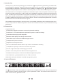
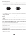
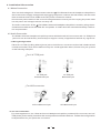
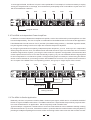
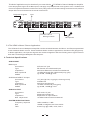
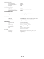
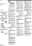
User's Manual
HPA6
6-Channel HEADPHONE AMPLIFIER
R
LTO
www.altoproaudio.com
Version 1.0 April 2002
English
SAFETY RELATED SYMBOLS
wire or disconnect the wiring of protective grounding
terminal.
CAUTION
Operating Conditions
This apparatus shall not be exposed to dripping or
splashing and that no objects filled with liquids,
such as vases, shall be placed on this apparatus.
To reduce the risk of fire or electric shock, do not
expose this apparatus to rain or moisture.
Do not use this apparatus near water.
Install in accordance with the manufacturer's
instructions. Do not install near any heat sources
such as radiators, heat registers, stoves, or other
apparatus (including amplifiers) that produce heat.
Do not block any ventilation openings.
No naked flame sources, such as lighted candles,
should be placed on the apparatus.
RISK OF ELECTRIC SHOCK
DO NOT OPEN
This symbol, wherever it appears, alerts you
to the presence of uninsulated dangerous voltage
inside the enclosure-voltage that may be sufficient to constitute a risk of shock.
This symbol ,wherever it appears ,alerts you
to important operating and maintenance
instructions in the accompanying literature .
Read the manual .
Protective grounding terminal .
Alternating current /voltage .
Hazardous live terminal .
ON: Denotes the apparatus turns on .
IMPORTANT SAFETY INSTRUCTIONS
OFF: Denotes the apparatus turns off ,because of
using the single pole switch ,be sure to unplug the
AC power to prevent any electric shock before you
proceed your service .
Read these instructions.
Follow all instructions.
Keep these instructions.
Heed all warnings.
Only use attachments/accessories specified by the
manufacturer.
WARNING: Describes precautions that should
be observed to prevent the danger of injury or
death to the user .
Power Cord and Plug
Do not defeat the safety purpose of the polarized
or grounding type plug. A polarized plug has two
blades with one wider than the other. A grounding
type plug has two blades and a third grounding
prong. The wide blade or the third prong are provided
for your safety. If the provided plug does not fit into
your outlet, consult an electrician for replacement
of the obsolete outlet.
Protect the power cord from being walked on or
pinched particularly at plugs, convenience receptacles ,
and the point where they exit from the apparatus.
CAUTION: Describes precautions that should
be observed to prevent danger of the apparatus .
WARNING
Power Supply
Ensure the source voltage matches the voltage of
the power supply before turning ON the apparatus.
Unplug this apparatus during lightning storms or when
unused for long periods of time .
External Connection
The external wiring connected to the output hazardous
live terminals requires installation by an instructed
person, or the use of ready-made leads or cords.
Cleaning
When the apparatus needs a cleaning, you can blow
off dust from the apparatus with a blower or clean
with rag etc. Don't use solvents such as benzol,
alcohol, or other fluids with very strong volatility and
flammability for cleaning the apparatus body.
Clean only with dry cloth.
Do not Remove any Cover
There are maybe some areas with high voltages
inside , to reduce the risk of electric shock, do not
remove any cover if the power supply is connected.
The cover should be removed by the qualified personnel
only.
No user serviceable parts inside.
Servicing
Refer all servicing to qualified personnel. To reduce
the risk of electric shock, do not perform any servicing
other than that contained in the operating instructions
unless you are qualified to do so .
Fuse
To prevent a fire, make sure to use fuses with specified
standard (current, voltage, type). Do not use a different
fuse or short circuit the fuse holder.
Before replacing the fuse, turn OFF the apparatus and
disconnected the power source.
Servicing is required when the apparatus has
been damaged in any way ,such as power supply
cord or plug is damaged , liquid has been spilled
or objects have fallen into the apparatus, the
apparatus has been exposed to rain or moisture,
does not operate normally, or has been dropped.
Protective Grounding
Make sure to connect the protective grounding to prevent
any electric shock before turning ON the apparatus.
Never cut off the internal or external protective grounding
1
Preface
Dear Customer:
Thanks for choosing
LTO HPA6 6-Channel Headphone Amplifier and thanks for choosing the
one of results of LTO AUDIO TEAM job and researches.
For our LTO AUDIO TEAM, music and sound are more than a job...are first of all passion and let us say...
our obsession!
We have been designing professional audio products for a long time in cooperation with some of the major
brands in the world in the audio field.
The LTO line presents unparalleled analogue and digital products made by Musicians for Musicians in
our R&D Centres in Italy, Netherlands, United Kingdom and Taiwan. The core of our digital audio products
is a sophisticated DSP (Digital sound processor) and a large range of state of the art algorithms which
have been developed by our Software Team for the last 7 years.
Because we are convinced you are the most important member of LTO AUDIO TEAM and the one confirming the quality of our job, we'd like to share with you our work and our dreams, pay attention to your
suggestions and your comments.
Following this idea we create our products and we will create the new ones! From our side, we guarantee
you and we will guarantee you also in future the best quality, the best fruits of our continuous researches
and the best prices.
Our LTO HPA6 6-Channel Headphone Amplifier is the result of many hours of listening and tests involving
common people, area experts, musicians and technicians.
The result of this effort is a versatile Headphone Amplifier featuring 6 separated channels, each channel
provides 3 push-button switches, 2 knob controls, 2 phone jacks and 4 LEDs . The common main section
contains 1knob control, 1 jack and 8 LEDs.
Nothing else to add, but that we would like to thank all the people that made the LTO HPA6 6-Channel
Headphone Amplifier a reality available to our customers, and thank our designers and all the LTO staff,
there to make possible the realization of products containing our idea of music and sound and there to
support you, our customers, in the best way, conscious that you are our best richness.
Thank you very much.
LTO AUDIO TEAM
2
TABLE OF CONTENTS
1. Introduction ......................................................................................................................4
2. Feature List .......................................................................................................................4
3. Control Elements. .............................................................................................................4
3.1 The Front Panel
3.2 The Rear Panel
4. Installation & Connection .................................................................................................7
4.1 Mains Connection
4.2 Audio Connection
a. Wiring Configuration
b. In Line Connection
4.3 Rack Mounting
5. Application........................................................................................................................8
5.1 The HPA6 as a Headphone Amplifier
5.2 The HPA6 as Independent Power Amplifiers
5.3 The HPA6 in Studio Application
5.4 The HPA6 in Mono/Stereo Application
6. Technical Specifications .................................................................................................10
7.Warranty ..........................................................................................................................12
3
1. Introduction
Thank you very much for expressing your confidence in LTO products by purchasing our HPA6 6-Channel Headphone Amplifier. With the HPA6 you have acquired an extremely musical and flexible 6-Channel Headphone Amplifier. Featuring six stereo headphone amplifiers, The LTO HPA6 6-Channel
Headphone Amplifier performs a number of necessary tasks, not all of which are headphone related.
The HPA6 6-Channel Headphone Amplifier provides Main Inputs on the rear panel and Direct In Input
on the front panel to drive any or all of the 6 stereo headphone amplifiers, when using the Direct In
Input, the Main Inputs signal will be interrupted automatically, the Main Outputs on the rear panel can
be used to interlink any number of HPA6s for expanding. The AUX In input on each channel is used
to add an additional input signal to the master signal, with the corresponding Balanced Control to
determine the mix ratio between the two signals.
The Headphone Out outputs on the front panel is connected in parallel to the rear panel output connectors, and provides an additional option to monitor the individual channels, esp. in the Rack mounting
application.
2. Feature List
Signal Rack Unit
Exceptionally rugged construction ensures long life and durability
Professional , universal headphone amplification system for studio and stage
6 individual stereo high-power amplifiers
Maximum audio quality even at high volume levels
Stereo AUX In per channel for additional signal source
6 independent input mix sections
Output level control per channel
Mono and LEFT/RIGHT MUTE buttons per channel for additional flexibility
3 headphone outputs per channel on front and rear panels
Precise 4-digit LED output level display per channel
Direct In on the front panel for additional stereo signal source
Paralleled main outputs to chain several HPA6 headphone amplifiers
Servo-balanced , gold-plated XLR and 1/4" TRS connectors
Manufactured Under ISO9001 Certified management system
3. Control Elements
INPUT LEVEL(dBu)
24
18
12
6
0
6
18
0
2
24
1
R
3
OUTPUT LEVEL(dBu)
4
12 CLIP
MUTE
5
L
0
2
12 CLIP
MUTE
R
3
OUTPUT LEVEL(dBu)
4
1
24
5
L
0
2
12 CLIP
MUTE
R
3
OUTPUT LEVEL(dBu)
4
24
5
1
L
0
2
12 CLIP
MUTE
R
3
OUTPUT LEVEL(dBu)
4
24
5
1
L
0
2
12 CLIP
MUTE
R
3
OUTPUT LEVEL(dBu)
4
24
5
1
L
0
2
12 CLIP
MUTE
R
4
5
1
4
MAIN IN
AUX
BALANCED
AUX IN
R
DIRECT IN
24
L
2
LTO
3
OUTPUT LEVEL(dBu)
12
3
5
1
0
6
6
0
OUTPUT GAIN
HEADPHONE OUT
MAIN IN
AUX
BALANCED
AUX IN
6
0
OUTPUT GAIN
HEADPHONE OUT
AUX
MAIN IN
BALANCED
AUX IN
6
0
OUTPUT GAIN
HEADPHONE OUT
AUX
BALANCED
AUX IN
6
0
OUTPUT GAIN
HEADPHONE OUT
AUX
BALANCED
AUX IN
6
0
OUTPUT GAIN
HEADPHONE OUT
AUX
BALANCED
AUX IN
MONO
MONO
MONO
MONO
MONO
MONO
STEREO
STEREO
STEREO
STEREO
STEREO
STEREO
HPA6
6
0
OUTPUT GAIN
HEADPHONE OUT
6-Channel
ON HEADPHONE
AMPLIFIER
OFF
INPUT GAIN
MAIN SECTION
CHANNEL 1
CHANNEL 2
CHANNEL 3
CHANNEL 4
CHANNEL 5
CHANNEL 6
POWER
The LTO HPA6 6-Channel Headphone Amplifier has six separated channels, each channel presents
3 Push-button switches, 2 knob controls , 2 phone jacks and 4 LEDs. The common main section contains 1 knob control,1 jack and 8 LEDs.
4
3.1 The F ront P anel
INPUT LEVEL(dBu)
24
18
12
6
6 10
5 12
3
0
6
18
24
L
3
0
2
4
12 CLIP
MUTE
R
5
1
4
MAIN IN
AUX
BALANCED
AUX IN
R
DIRECT IN
3
OUTPUT LEVEL(dBu)
12
2
LTO
11
5
1
6
0
OUTPUT GAIN
HEADPHONE OUT
MONO
6
0
STEREO
INPUT GAIN
MAIN SECTION
1
CHANNEL 1
8
2
7
4
9
1.Direct In Input: The Direct In Input is used to feed the signals coming from an external source. While
using the Direct In Input, the Main signal applied on the rear panel is interrupted automatically.
2.Input Gain Control: This control sets the input signal level coming from Main/Direct In.
3.Input Level Meter: This 8-digit Input Level Meter informs you about the input signal level within a
range from -24dBu to +18dBu.
4.Aux In Input: The Aux In Input is used to feed the further input signal, which can be mixed with the Main/
Direct In signal via Balanced Control.
5.L Mute Switch: This push-button mutes the Left input signal.
6.R Mute Switch: This push-button mutes the Right input signal.
7.Mode Switch: This push-button switches the operational mode between Mono and Stereo. Press this
button for Mono application, and the Mono LED (8) lights up.
8.Mono LED: This LED informs you the current operational mode. Press the Mode Switch(7) for Mono
application, this LED lights up.
9.Headphone Out Output: This 1/4" TRS phone jack is connected in parallel to the rear panel output
connectors, and provides an additional option to monitor the individual channels. When this unit is permanently installed in rack, this proves to be a useful function.
10.Balanced Control: This control sets the proportion between the Main/Direct In signal and the input signal
applied to Aux In Input.
11.Output Gain Control: This control sets the volume of the individual channels and refers to both the
Left & Right Channel and the Headphone Out.
12.Output Level Meter: This 4-digit Output Level Meter informs you about the output signal level within
a range from 24dBu to +12dBu. If the Clip LED lights up, you should turn down the Input Gain Control
or/and the individual Output Gain Control (only for the Channel incurs Clip) to avoid any distortion.
3.2 The Rear Panel
TIP/PIN 2
RING/PIN 3
SLEEVE/PIN 1
110-120V
AC INPUT
220-240V
95-120V 60Hz
/210-240V 50Hz
Rated Power
Consumption 40W
TIP/PIN 2
RING/PIN 3
SLEEVE/PIN 1
TIP:L- CHANNEL
RING:R- CHANNEL
MIN. LOAD 100OHMS
TIP/PIN 2
RING/PIN 3
SLEEVE/PIN 1
PUSH
NEW
TIP/PIN 2
RING/PIN 3
SLEEVE/PIN 1
TIDE
3
3
2
PUSH
NEW
TIDE
2
1
FUSE:
210-240V: T160mAL 250VAC
95-120V: 315mA 250VAC
REPLACE FUSE WITH
CORRECT TYPE ONLY
HEADPHONE OUT 6
13
14
22
HEADPHONE OUT 5
21
HEADPHONE OUT 4 HEADPHONE OUT 3 HEADPHONE OUT 2 HEADPHONE OUT 1
20
19
18
17
5
MAIN OUTPUT RIGHT
MAIN OUTPUT LEFT
16
MAIN INPUT LEFT
MAIN INPUT RIGHT
15
1
13. Fuse holder / Voltage selector
This is a dual voltage unit. Before you attempt to connect and operate the unit, please make sure that your
local voltage matches the voltage on the fuse-holder cover.
Caution: The fuse protecting the AC supplies circuits of this unit. The fuse can only be changed by
a qualified technician, in the event of a fault or changing the supply voltage. If the fuse continues to
blow after replacing, discontinue use of this unit before repaired.
220-240V
110-120V
220-240V
110-120V
THIS IS SET FOR
110V AC TO 120V
AC OPERATION
THIS IS SET FOR
220V AC TO 240V
AC OPERATION
The fuse-holder above the AC connector on the rear of the chassis has 3 triangular markers(please refer to
the above pictures), with two of these triangles opposing each other, your unit is set to the operating voltage
printed next to these markers.
To change, pull fuse-holder out and rotate 180 ,then push in again.
14. AC Inlet
This connector is meant for the connection of the supplied main cord. Do not insert power cable into unit
until voltage has been correctly set. Do not plug power cable into AC power until voltage has been correctly set.
15.Main Input Connectors: These connectors are used to input the stereo signal. You can input the main
signal via the balanced 1/4" TRS phone jack or XLR connector.
16.Main Output Connectors: These connectors are used to output the stereo signal. You can output
the main signal via the balanced 1/4" TRS phone jack or XLR connector. In some typical field, you can
also use these connectors to interlink several Headphone Amplifiers.
17.Headphone Out1: In Parallel with the Headphone Out on the front panel (for Channel 1), these are the
headphone outputs of Channel 1.
18.Headphone Out2: In Parallel with the Headphone Out on the front panel (for Channel 2), these are the
headphone outputs of Channel 2.
19.Headphone Out3: In Parallel with the Headphone Out on the front panel (for Channel 3), these are the
headphone outputs of Channel 3.
20.Headphone Out4: In Parallel with the Headphone Out on the front panel (for Channel 4), these are the
headphone outputs of Channel 4.
21.Headphone Out5: In Parallel with the Headphone Out on the front panel (for Channel 5), these are the
headphone outputs of Channel 5.
22.Headphone Out6: In Parallel with the Headphone Out on the front panel (for Channel 6), these are the
headphone outputs of Channel 6.
6
4. Installation & C onnection
4.1 Mains Connection
This is a dual voltage unit. Please ensure that the LTO HPA6 6-Channel Headphone Amplifier is
set to the correct supply voltage before plugging the power cord into the wall outlet, use the same
fuse as marked on the fuse holder at the AC power connection socket.
Do not insert power cable into the unit until voltage has been correctly set. Do not plug the power cable
into AC power until voltage has been correctly set.
The mains connection of the LTO HPA6 6-Channel Headphone Amplifier is made by using the enclosed mains cable and a standard IEC receptacle. It meets all of the international safety certification requirements.
4.2 Audio C onnection
The HPA6 6-Channel Headphone Amplifier presents with balanced XLR connectors and 1/4" TRS phone
jack and it can be interfaced by several ways to support a variety of applications without any signal loss.
a. Wiring Configuration
Either the 1/4" TRS (Tip-Ring-Sleeve) phone jack or the XLR servo connector can be wired in balanced and
unbalanced modes, which will be determined by the actual application status, Please wire your systems
as the following examples:
For 1/4" TRS jack
1/4"TRS jack
Unbalanced input
1/4"TRS jack
Balanced input
For XLR connector
XLR Unbalanced input
XLR B alanced input
b. In Line Connection
For these applications, the HPA6 6-Channel Headphone Amplifier provides XLR connectors and 1/4"
TRS phone jack to easily interface with most professional audio devices. Follow the configuration
examples below for your particular connection.
7
Balanced
TIP RING SLEEVE
SLEEVE RING TIP
Tip
Ring
Sleeve
Tip
Ring
Sleeve
1
2
3
1
2
3
Tip
Ring
Sleeve
1
2
3
Tip
Ring
Sleeve
1
2
3
Tip
1
2
3
TIP RING SLEEVE
Unbalanced
TIP RING SLEEVE
Sleeve
TIP SLEEVE
1
2
3
Tip
TIP SLEEVE
TIP RING SLEEVE
Centre
Screen
Tip
Sleeve
Sleeve
Tip
Ring
Sleeve
Tip
Ring
Sleeve
Tip
Centre
Screen
SLEEVE TIP
SLEEVE RING TIP
Sleeve
TIP SLEEVE
TIP RING SLEEVE
Tip
Ring
Sleeve
1
2
3
Centre
Screen
1
2
3
4.3 Rack M ounting
The most secure mounting is on a universal rack shelf available from various rack manufactures or your
music dealer. The HPA6 6-Channel Headphone Amplifier fits into one standard 19" rack unit of space.
Please allow at least an additional 4" depth for the connectors on the rear panel. Be sure that there is
enough air space around the unit for sufficient ventilation and please do not place the HPA6 6-Channel
Headphone Amplifier on high temperature devices such as power amplifiers etc. to avoid overheating.
5.Application
This section presents some typical applications of our LTO HPA6 6-Channel Headphone Amplifier.
Please reserve your time to well understand the control elements ( see Chapter 3 ) and the following
application examples, so as to be able to fully exploit the HPA6 6-Channel Headphone Amplifier.
5.1 The HPA6 as a Headphone Amplifier
This is the basic application for HPA6 6-Channel Headphone Amplifier. While using the HPA6 as a Headphone Amplifier, please apply the program source to Main / Direct In Inputs, and connect the headphone
cable to one of the appropriate outputs. Turn up the Input Gain and the Balanced controls to center
position. The Input Gain control is used to boost or attenuate the general volume of all the headphones,
while the individual Output Gain controls are used to set the desired channel volume.
Three headphones can be connected per channel each time, on condition that the resulting total connection impedance does not fall below 100 Ohms (Although the power amplifiers are resistant to temporary
short circuits, an impedance drop will not incur any damage, but, it can affect the quality of reproduction,
in terms of long term damage and distortion). If this is not enough, you can interlink any number of HPA6
via the Main Outputs.
The Headphone Out on the front panel is connected in parallel to the rear panel output connectors, and it
provides an additional option to monitor the individual channels. When this unit is permanently mounted
in the rack, this proves to be a useful function.
8
In some typical fields, the Direct In Input is more preferable. For example, it is often necessary to replay
a song for the performer in the stage, this can be easily and rapidly done via this Direct In jack even if in
the rack installation condition.
out1
INPUT LEVEL(dBu)
24
18
12
6
0
6
24
18
0
L
2
DIRECT IN
2
24
5
1
R
0
L
out3
3
OUTPUT LEVEL(dBu)
4
12 CLIP
MUTE
2
R
24
0
L
5
1
3
OUTPUT LEVEL(dBu)
4
12 CLIP
MUTE
out4
2
R
3
OUTPUT LEVEL(dBu)
4
12 CLIP
MUTE
24
0
L
5
1
out5
2
R
3
OUTPUT LEVEL(dBu)
4
12 CLIP
MUTE
24
0
L
5
1
out6
2
R
3
OUTPUT LEVEL(dBu)
4
12 CLIP
MUTE
24
0
L
5
1
2
4
12 CLIP
MUTE
R
5
1
4
MAIN IN
AUX
BALANCED
AUX IN
R
LTO
3
OUTPUT LEVEL(dBu)
12
3
out2
6
0
OUTPUT GAIN
HEADPHONE OUT
MAIN IN
AUX
BALANCED
AUX IN
5
1
MONO
6
0
6
0
OUTPUT GAIN
HEADPHONE OUT
AUX
MAIN IN
BALANCED
AUX IN
MONO
STEREO
6
0
OUTPUT GAIN
HEADPHONE OUT
AUX
BALANCED
AUX IN
MONO
STEREO
6
0
OUTPUT GAIN
HEADPHONE OUT
AUX
BALANCED
AUX IN
MONO
STEREO
6
0
OUTPUT GAIN
HEADPHONE OUT
AUX
BALANCED
AUX IN
MONO
STEREO
HPA6
6
0
OUTPUT GAIN
HEADPHONE OUT
6-Channel
ON HEADPHONE
AMPLIFIER
MONO
STEREO
OFF
STEREO
INPUT GAIN
MAIN SECTION
CHANNEL 2
CHANNEL 1
CHANNEL 3
CHANNEL 4
CHANNEL 5
POWER
CHANNEL 6
Direct in
program source
5.2 The HPA6 as Independent Power Amplifiers
In addition to use the HPA6 as the Headphone Amplifier, each of the 6-Channel's power amplifiers can also
be used independently. The Aux In Inputs in combination with the Balanced Control serve this application.
If the Balanced Control is set to "Aux" position (clockwise stop position), the Main signal is muted,
only the signals coming from Aux In Input are routed to the power amplifier.
By configuring the HPA6 as completely independent power amplifiers, you can insert up to six independent
stereo program sources, thus, six different and individual mixes for up to six musicians can be created.
As with a stage monitor system, you can give each musician a specific configuration of instruments and
create a personal mix for him or her that is musically inspiring. Or you can establish different signal paths
for the interpreters in a conference system. Configure sub-groups or create pre-mixes using the effects
and/or monitor facilities of your mixing console. Set the Balance Control to "Aux" position and connect the
Aux In Inputs of the HPA6 to the corresponding monitor, sub-group or single output of the console.
out1
INPUT LEVEL(dBu)
24
18
12
6
0
6
18
24
L
2
0
2
24
MAIN IN
AUX
BALANCED
DIRECT IN
5
1
R
3
OUTPUT LEVEL(dBu)
4
12 CLIP
MUTE
L
0
2
12 CLIP
MUTE
out3
R
3
OUTPUT LEVEL(dBu)
4
24
5
1
L
0
2
12 CLIP
MUTE
out4
R
3
OUTPUT LEVEL(dBu)
4
24
5
1
L
0
2
12 CLIP
MUTE
out5
R
3
OUTPUT LEVEL(dBu)
4
24
5
1
L
0
2
12 CLIP
MUTE
out6
R
3
OUTPUT LEVEL(dBu)
4
24
5
1
L
0
2
12 CLIP
MUTE
R
4
5
1
4
R
LTO
3
OUTPUT LEVEL(dBu)
12
3
out2
AUX IN
6
0
OUTPUT GAIN
HEADPHONE OUT
MAIN IN
AUX
BALANCED
AUX IN
5
1
MONO
0
6
MONO
STEREO
6
0
OUTPUT GAIN
HEADPHONE OUT
AUX
MAIN IN
BALANCED
AUX IN
6
0
OUTPUT GAIN
HEADPHONE OUT
MONO
STEREO
AUX
BALANCED
AUX IN
MONO
STEREO
6
0
OUTPUT GAIN
HEADPHONE OUT
AUX
BALANCED
AUX IN
MONO
STEREO
6
0
OUTPUT GAIN
HEADPHONE OUT
AUX
BALANCED
AUX IN
HPA6
6
0
OUTPUT GAIN
HEADPHONE OUT
6-Channel
ON HEADPHONE
AMPLIFIER
MONO
STEREO
OFF
STEREO
INPUT GAIN
MAIN SECTION
CHANNEL 1
AUX in 1
CHANNEL 2
AUX in 2
CHANNEL 3
CHANNEL 4
AUX in 3
CHANNEL 5
AUX in 4
CHANNEL 6
AUX in 5
POWER
AUX in 6
monitor paths
M ixing C onsole
5.3 The HPA6 in Studio Application
Basically, the Aux In Inputs are used to feed a further input signal, which can be mixed with the Main/
Direct In signal via Balanced Control. The Balanced Control supersedes the previously required monitor mixer and allows for an application that is frequently used in Studio field.
Typical example : Suppose a vocalist wants to record a vocal track that is to be added to already existing
instrumental tracks. Up to mow, it has been common practice that the vocalist listens to the playback by
pressing a headphone pad against one ear, while controlling his/her own voice with the another free ear.
9
This kind of application may be obsolete if you come with the LTO HPA6 6-Channel Headphone Amplifier.
Insert the playback signal via the Main Inputs, and apply the preamplifiered vocal signal to Aux In. The Balanced
Control is adjusted so that the vocalist can hear a pretty perfect mix of both backing tracks and vocals, with the
Output Gain Control to determine the overall volume level.
P layback P rogram
Out1
M ain I nput
INPUT LEVEL(dBu)
24
18
12
6
0
6
18
24
L
0
2
24
MAIN IN
AUX
BALANCED
DIRECT IN
5
1
R
3
OUTPUT LEVEL(dBu)
4
12 CLIP
MUTE
L
0
2
12 CLIP
MUTE
R
3
OUTPUT LEVEL(dBu)
4
24
5
1
L
0
2
12 CLIP
MUTE
R
3
OUTPUT LEVEL(dBu)
4
24
5
1
L
0
2
12 CLIP
MUTE
R
3
OUTPUT LEVEL(dBu)
4
24
5
1
L
0
2
12 CLIP
MUTE
R
3
OUTPUT LEVEL(dBu)
4
24
5
1
L
0
2
12 CLIP
MUTE
R
4
5
1
4
R
LTO
3
OUTPUT LEVEL(dBu)
12
3
2
AUX IN
6
0
OUTPUT GAIN
HEADPHONE OUT
MAIN IN
AUX
BALANCED
AUX IN
5
1
0
6
6
0
OUTPUT GAIN
HEADPHONE OUT
AUX
MAIN IN
BALANCED
AUX IN
6
0
OUTPUT GAIN
HEADPHONE OUT
AUX
BALANCED
AUX IN
6
0
OUTPUT GAIN
HEADPHONE OUT
AUX
BALANCED
AUX IN
6
0
OUTPUT GAIN
HEADPHONE OUT
AUX
BALANCED
AUX IN
MONO
MONO
MONO
MONO
MONO
MONO
STEREO
STEREO
STEREO
STEREO
STEREO
STEREO
HPA6
6
0
OUTPUT GAIN
HEADPHONE OUT
6-Channel
ON HEADPHONE
AMPLIFIER
OFF
INPUT GAIN
MAIN SECTION
CHANNEL 2
CHANNEL 1
CHANNEL 3
CHANNEL 4
CHANNEL 5
CHANNEL 6
POWER
AUX In 1
Line Out Mic In
M ixing C onsole
Microphone
5.4 The HPA6 in Mono / Stereo Application
The HPA6 6-Channel Headphone Amplifier can be switched between the Mono and Stereo operational
mode via Mode Switch control. Press the Mode Switch for Mono application, the Mono LED (8) lights up.
In Mono application, the input two signals are combined together and the resulting mono signal routes to
both the Left and Right Headphone Out Outputs.
6. Technical Specifications
AUDIO INPUT
MAIN input
Connectors
Type
Impedance
Max.input level
CMRR
X L R and 1/4" jack
RF filtered, servo balanced input
50 kOhms balanced, 25 kOhms unbalanced
+21 dBu balanced and unbalanced (unity gain)
typ.40 dB, >55 dB @ 1kHz
AUX IN and DIRECT IN input
Connectors
Type
Impedance
Max.input level
CMRR
1/4" jack (tip=left, ring=right, sleeve=ground)
unbalanced
25 kOhms unbalanced
+21 dBu unbalanced (unity gain)
typ,40 dB, >55 dB @ 1 kHz
AUDIO OUTPUT
Connectors
Type
Impedance
Max. output level
XLR and 1/4" jack
balanced /unbalanced
dependent on input balance
+21 dBu balanced and unbalanced
SYSTEM SPECIFICATIONS
Frequency response
S/N
THD
10 H z to 50kHz,+/-3dB
>90dB, unweighted, 22 Hz to 22kHz
0.005% typ.@+4 dBu, 1kHz, Gain 1
10
POWER AMPLIFIER
Max.output power
Min.output impedance
Max.gain
+21dBm
100Ohms
+20dB
FUNCTION CONTROLS
Input level
Balanced per channel
Output level per channel
variable
mix between aux and main signal
variable
FUNCTION SWI T CHES
Left mute
Right mute
Mode
mutes the left signal of this channel
mutes the right signal of this channel
switches channel to mono/stereo
INDICATORS
Input level
8-digit LED display: -24/-18/-12/-6/0/+6/+12/ +18dBu
Output level
4-digit LED display: -24/0/+12 dBu/CLIP
POWER SUPPLY
Connector type
3-pole IEC, grounded
Type
Servo controlled, stabilized
Mains supply
95-120V
Power Rating
40 W
Fuse
210-240V: T160mAL 250VAC
95-120V: 315mA 250VAC
Dimension
Net weight
483(W)
/210-240V
,60-50Hz
PHYSICAL
217 (D)
2.9kg(6.39lb)
11
44 (H)mm(19" 8.54" 1.7")
7. WARRANTY
1. WARRANTY REGISTRATION CARD
To obtain Warranty Service, the buyer should first fill out and return the enclosed Warranty Registration
Card within 10 days of the Purchase Date.
All the information presented in this Warranty Registration Card gives the manufacturer a better understanding of the sales status, so as to purport a more effective and efficient after-sales warranty service.
Please fill out all the information carefully and genuinely, miswriting or absence of this card will void your
warranty service.
2. RETURN NOTICE
2.1 In case of return for any warranty service, please make sure that the product is well packed in its original
shipping carton, and it can protect your unit from any other extra damage.
2.2 Please provide a copy of your sales receipt or other proof of purchase with the returned machine ,and
give detail information about your return address and contact telephone number .
2.3 A brief description of the defect will be appreciated.
2.4 Please prepay all the costs involved in the return shipping, handling and insurance.
3. TERMS AND CONDITIONS
3.1
LTO warrants that this product will be free from any defects in materials and/or workmanship for
a period of 1 year from the purchase date if you have completed the Warranty Registration Card in
time.
3.2 The warranty service is only available to the original consumer, who purchased this product directly
from the retail dealer, and it can not be transferred.
3.3 During the warranty service, LTO may repair or replace this product at its own option at no charge to
you for parts or for labor in accordance with the right side of this limited warranty.
3.4 This warranty does not apply to the damages to this product that occurred as the following conditions:
Instead of operating in accordance with the user's manual thoroughly, any abuse or misuse of this
product.
Normal tear and wear.
The product has been altered or modified in any way.
Damage which may have been caused either directly or indirectly by another product / force / etc
Abnormal service or repairing by anyone other than the qualified personnel or technician.
And in such cases, all the expenses will be charged to the buyer.
3.5 In no event shall LTO be liable for any incidental or consequential damages. Some states do not allow
the exclusion or limitation of incidental or consequential damages, so the above exclusion or limitation
may not apply to you.
3.6 This warranty gives you the specific rights, and these rights are compatible with the state laws, you
may also have other statutory rights that may vary from state to state.
12