1
ATL:
Atlas Transformation Language
ATL User Manual
- version 0.7 -
February 2006
by
ATLAS group
LINA & INRIA
Nantes
Content
1
Introduction ................................................................................................................................................. 1
2
An Introduction to Model Transformation ............................................................................................... 2
3
2.1
The Model-Driven Architecture ........................................................................................................... 2
2.2
Model Transformation ......................................................................................................................... 3
Overview of the Atlas Transformation Language .................................................................................... 5
3.1
ATL module.......................................................................................................................................... 5
3.1.1
Structure of an ATL module ........................................................................................................... 5
3.1.1.1
Header section ....................................................................................................................... 5
3.1.1.2
Import section ........................................................................................................................ 6
3.1.1.3
Helpers................................................................................................................................... 6
3.1.1.4
Rules ...................................................................................................................................... 7
3.1.2
Module execution modes ................................................................................................................ 9
3.1.2.1
Normal execution mode......................................................................................................... 9
3.1.2.2
Refining execution mode ....................................................................................................... 9
3.1.3
Module execution semantics ......................................................................................................... 11
3.1.3.1
Default mode execution semantics ...................................................................................... 11
3.1.3.2
Refining mode execution semantics .................................................................................... 12
3.2
ATL Query.......................................................................................................................................... 12
3.2.1
Structure of an ATL query ............................................................................................................ 12
3.2.2
Query execution semantics............................................................................................................ 13
3.3
4
ATL Library ....................................................................................................................................... 13
The ATL Language ................................................................................................................................... 14
4.1
Data types .......................................................................................................................................... 14
4.1.1
OclType operations ....................................................................................................................... 15
4.1.2
OclAny operations ........................................................................................................................ 15
4.1.3
The ATL Module data type ........................................................................................................... 16
4.1.4
Primitive data types....................................................................................................................... 17
4.1.4.1
Boolean data type operations............................................................................................... 17
4.1.4.2
String data type operations .................................................................................................. 17
4.1.4.3
Numerical data type operations ........................................................................................... 18
4.1.4.4
Examples ............................................................................................................................. 19
4.1.5
Collection data types ..................................................................................................................... 20
4.1.5.1
Operations on collections..................................................................................................... 20
4.1.5.2
Sequence data type operations............................................................................................. 21
4.1.5.3
Set data type operations ....................................................................................................... 21
4.1.5.4
OrderedSet data type operations .......................................................................................... 22
4.1.5.5
Bag data type operations...................................................................................................... 22
4.1.5.6
Iterating over collections ..................................................................................................... 23
4.1.5.7
Examples ............................................................................................................................. 24
4.1.6
Enumeration data types ................................................................................................................. 25
4.1.7
Tuple data type.............................................................................................................................. 26
4.1.8
Map data type................................................................................................................................ 26
4.1.9
Model element data type ............................................................................................................... 27
4.1.9.1
Examples ............................................................................................................................. 27
4.2
ATL Comments................................................................................................................................... 28
4.3
OCL Declarative Expressions............................................................................................................ 28
4.3.1
If expression .................................................................................................................................. 28
4.3.2
Let expression ............................................................................................................................... 29
4.3.3
Other expressions .......................................................................................................................... 30
4.3.4
Expressions tips & tricks............................................................................................................... 30
4.4
ATL Helpers ....................................................................................................................................... 31
4.4.1
Helpers .......................................................................................................................................... 31
4.4.2
Attributes....................................................................................................................................... 32
4.4.3
Limitations .................................................................................................................................... 33
4.5
ATL Rules........................................................................................................................................... 34
4.5.1
ATL imperative code .................................................................................................................... 34
4.5.1.1
The assignment statement.................................................................................................... 34
4.5.1.2
The if statement ................................................................................................................... 35
4.5.1.3
The for statement ................................................................................................................. 36
4.5.1.4
Current limitations ............................................................................................................... 36
4.5.2
Matched Rules............................................................................................................................... 36
4.5.2.1
Source pattern ...................................................................................................................... 37
4.5.2.2
Local variables section ........................................................................................................ 38
4.5.2.3
Simple target pattern element .............................................................................................. 38
4.5.2.4
Iterative target pattern element ............................................................................................ 40
4.5.2.5
Imperative block section...................................................................................................... 42
4.5.3
Called Rules .................................................................................................................................. 43
5
4.6
ATL Queries ....................................................................................................................................... 44
4.7
ATL Keywords.................................................................................................................................... 45
4.8
ATL Tips & Tricks.............................................................................................................................. 45
The ATL Tools........................................................................................................................................... 47
5.1
Installation ......................................................................................................................................... 47
5.1.1
Installing ATL............................................................................................................................... 47
5.1.2
Installing AM3 .............................................................................................................................. 48
5.1.2.1
Installing AM3 from binaries .............................................................................................. 48
5.1.2.2
Installing AM3 from sources ............................................................................................... 48
5.2
Perspectives ....................................................................................................................................... 49
5.2.1
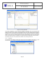
ATL perspective............................................................................................................................ 49
5.2.1.1
Navigator ............................................................................................................................. 50
5.2.1.2
Editors.................................................................................................................................. 52
5.2.1.3
Outline ................................................................................................................................. 54
5.2.1.4
Problems .............................................................................................................................. 55
5.2.1.5
Properties ............................................................................................................................. 55
5.2.1.6
Error Log ............................................................................................................................. 57
5.2.1.7
Console ................................................................................................................................ 57
5.2.2
ATL Debug perspective ................................................................................................................ 57
5.2.2.1
Debug .................................................................................................................................. 58
5.2.2.2
Variables.............................................................................................................................. 59
5.2.2.3
Breakpoints.......................................................................................................................... 59
5.2.2.4
Editors.................................................................................................................................. 59
5.2.2.5
Outline ................................................................................................................................. 59
5.2.2.6
Console ................................................................................................................................ 60
5.2.2.7
Tasks.................................................................................................................................... 60
5.2.3
AM3 perspective ........................................................................................................................... 60
5.3
Programming ATL ............................................................................................................................. 61
5.3.1
Creating an ATL project ............................................................................................................... 62
5.3.2
Designing metamodels with KM3................................................................................................. 63
5.3.3
Creating an ATL file ..................................................................................................................... 65
5.3.3.1
The ATL File Wizard .......................................................................................................... 65
5.3.3.2
Creating an ATL file from scratch....................................................................................... 67
5.3.4
Compiling an ATL file.................................................................................................................. 67
5.3.5
Setting up an ATL run launch configuration................................................................................. 68
5.3.5.1
The ATL Configuration tab ................................................................................................. 70
5.3.5.2
The Model Choice tab ......................................................................................................... 70
5.3.5.3
The Common tab ................................................................................................................. 72
5.3.6
Running an ATL launch configuration.......................................................................................... 74
5.4
Debugging ATL.................................................................................................................................. 74
5.4.1
Managing breakpoints ................................................................................................................... 75
5.4.1.1
Setting/Removing breakpoints............................................................................................. 75
5.4.1.2
Activating/Deactivating breakpoints ................................................................................... 77
5.4.1.3
Limitations........................................................................................................................... 77
5.4.2
Creating an ATL Debug launch configuration .............................................................................. 77
5.4.3
Running an ATL Debug launch configuration .............................................................................. 78
5.4.4
Debugging actions......................................................................................................................... 78
5.4.5
Displaying variables values........................................................................................................... 80
6
Additional ATL Resources ....................................................................................................................... 82
7
Conclusion.................................................................................................................................................. 83
8
References .................................................................................................................................................. 84
Appendix A
The MMAuthor metamodel................................................................................................... 85
Appendix B
The MMPerson metamodel ................................................................................................... 86
Appendix C
The Biblio metamodel ............................................................................................................ 87
Appendix D
The Table metamodel............................................................................................................. 88
Figures List
Figure 1. Conformance relation ................................................................................................. 2
Figure 2. Meta relations ............................................................................................................. 2
Figure 3. The model-driven architecture.................................................................................... 3
Figure 4. An overview of model transformation........................................................................ 4
Figure 5. Overview of the Author to Person ATL transformation............................................. 4
Figure 6. The SimpleMetamodel metamodel ........................................................................... 10
Figure 7. The ATL data types metamodel................................................................................ 15
Figure 8. Simple inheritance case ............................................................................................ 45
Figure 9. Checking AM3 projects out...................................................................................... 48
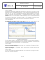
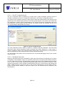
Figure 10. The ATL perspective .............................................................................................. 50
Figure 11. The Navigator view ................................................................................................ 51
Figure 12. Contextual menu in the Navigator view ................................................................. 51
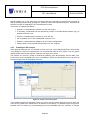
Figure 13. Default editor of a file type..................................................................................... 53
Figure 14. The Sample Ecore Model Editor ............................................................................ 53
Figure 15. Cursors synchronization between the Outline and the ATL Editor views ............. 54
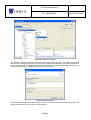
Figure 16. Breakpoint highlighting in the ATL Editor view.................................................... 55
Figure 17. Properties view with the Sample Ecore Model Editor............................................ 56
Figure 18. Properties view with the ATL Editor...................................................................... 57
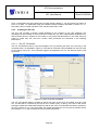
Figure 19. The ATL Debug perspective................................................................................... 58
Figure 20. The Breakpoints view ............................................................................................. 59
Figure 21. The AM3 perspective.............................................................................................. 60
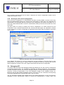
Figure 22. Injecting an ATL file into an ATL Ecore model .................................................... 61
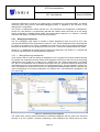
Figure 23. Creation of an ATL project..................................................................................... 62
Figure 24. The ATL Project Creator ........................................................................................ 63
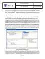
Figure 25. Creation of a new file.............................................................................................. 64
Figure 26. New File wizard...................................................................................................... 64
Figure 27. Launch of the ATL File Wizard ............................................................................. 65
Figure 28. The ATL File Wizard ............................................................................................. 66
Figure 29. A module template generated by the ATL File Wizard.......................................... 67
Figure 30. Launch of the run lauch configuration wizard........................................................ 68
Figure 31. Creating a new run ATL launch configuration....................................................... 69
Figure 32. Creating a new ATL run launch configuration....................................................... 69
Figure 33. The ATL Configuration tab .................................................................................... 70
Figure 34. The Model Choice tab............................................................................................. 71
Figure 35. The Common tab .................................................................................................... 73
Figure 36. Shortcuts to ATL run launch configuration............................................................ 74
Figure 37. Positionning new breakpoints................................................................................. 75
Figure 38. Localizing breakpoints in the ATL Editor.............................................................. 76
Figure 39. Removing breakpoints ............................................................................................ 77
Figure 40. Activating/Deactivating breakpoints ...................................................................... 77
Figure 41. Swithing to the ATL Debug perspective ................................................................ 78
Figure 42. Calling debugging actions from contextual menu .................................................. 79
Figure 43. Navigating variables content .................................................................................. 80
Figure 44. The MMAuthor metamodel .................................................................................... 85
Figure 45. The MMPerson metamodel .................................................................................... 86
Figure 46. The Biblio metamodel ............................................................................................ 87
ATL Documentations
ATL User Manual
Date 21/03/2006
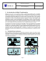
1 Introduction
ATL, the Atlas Transformation Language, is the ATLAS INRIA & LINA research group’s answer to the
OMG MOF [1]/QVT RFP [2]. It is a model transformation language specified as both a metamodel and
a textual concrete syntax. In the field of Model-Driven Engineering (MDE), ATL provides developers
with a mean to specify the way to produce a number of target models from a set of source models.
The ATL language is a hybrid of declarative and imperative programming. The preferred style of
transformation writing is the declarative one: it enables to simply express mappings between the
source and target model elements. However, ATL also provides imperative constructs in order to ease
the specification of mappings that can hardy be expressed declaratively.
An ATL transformation program is composed of rules that define how source model elements are
matched and navigated to create and initialize the elements of the target models. Besides basic model
transformations, ATL defines an additional model querying facility that enables to specify requests
onto models. ATL also allows code factorization through the definition of ATL libraries.
Developed over the Eclipse platform, the ATL Integrated Development Environment (IDE) [3] provides
a number of standard development tools (syntax highlighting, debugger, etc.) that aim to ease the
design of ATL transformations. The ATL development environment also offers a number of additional
facilities dedicated to models and metamodels handling. These features include a simple textual
notation dedicated to the specification of metamodels, but also a number of standard bridges between
common textual syntaxes and their corresponding model representations.
The present manual aims at providing both an exhaustive reference of the ATL transformation
language and a comprehensive guide for the users of the ATL IDE. For this purpose, this manual is
organized in three main parts: the first part (Section 2 and Section 3) introduces the main concepts of
model transformation and provides an overview of the structure and the semantics of the ATL
language. The second part (corresponding to Section 4) focuses on the description of the ATL
language while the last part (Section 5) deals with the use of the ATL tools.
The detailed structure of the document looks as follows:
• Section 2 provides a short introduction to the model transformation area;
• Section 3 offers an overview of the ATL capabilities;
• Section 4 is dedicated to the description of the ATL language;
• Section 5 describes the IDE that has been developed around the ATL transformation
language;
• Section 6 provides ATL programmers with a number of pointers to available ATL resources;
• Finally, Section 7 concludes the document.
Page 1
ATL Documentations
ATL User Manual
Date 21/03/2006
2 An Introduction to Model Transformation
Models are now part of an increasing number of engineering processes (such as software
engineering). However, in most cases, they are still confined to a simple documentation role instead of
being actively integrated into the engineering process. As opposed to this passive approach, the field
of Model-Driven Engineering (MDE) aims to consider models as first class entities. It also considers
that the different kinds of handled items (such as the tools, the repositories, etc.) can be viewed and
represented as models. The model-driven approach supposes to provide model designers and
developers with a set of operations dedicated to the manipulation of models. In this context, model
transformation appears to be a central operation for model handling: it aims to make it possible to
specify the way to produce a number of target models based on a set of source models. In the scope
of the model-driven engineering, it is assumed that model transformations, as any other model-based
tool, can be modelled, which means that they have to be considered themselves as models.
This section aims to provide an overview of the main MDE concepts, with a particular focus on model
transformation. To this end, it first presents, in Section 2.1, the organisation of the model-driven
architecture. This first section addresses the model definition mechanisms that constitute the core of
the MDE area: it introduces the notions of models, metamodels and metametamodels, as well as the
conformance relation that relates these different artefacts. The second part of the section more
particularly deals with model transformation. It provides an overview of the conceptual model
transformation architecture and detailed the way this conceptual architecture is matched to the ATL
language.
2.1
The Model-Driven Architecture
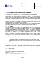
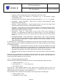
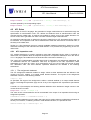
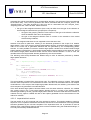
Models constitute the basic pieces of the model-driven architecture. Indeed, in the field of modeldriven engineering, a model is defined according to the semantics of a model of models, also called a
metamodel. A model that respects the semantics defined by a metamodel is said to conform to this
metamodel. As an example, Figure 1 illustrates the conformance relation between a Petri net model
and the Petri Nets metamodel.
Petri Net Metamodel
Petri Net
+net
1
Petri Net Metamodel
Petri Net Elt
Petri Net
0..n
+element
Node
name: String
Transition
+net
1
+to
1
+from
1
Arc
+in
0..n
+out
0..n
Petri Net Elt
0..n
+element
Node
name: String
Place
Transition
+to
1
+from
1
Place
meta relations
conformsTo
Petri Net Model
Deleted
Arc
+in
0..n
+out
0..n
Lost
Deleted
Deletion
Lost
Loss
Return
Deletion
Putting into
service
Loss
Return
Putting into
service
Available
Lent
Lending
Available
Lent
Petri Net Model
Lending
Figure 2. Meta relations
Figure 1. Conformance relation
Page 2
ATL Documentations
ATL User Manual
Date 21/03/2006
conformsTo
Metametamodel
meta
Metametamodel element
meta
conformsTo
Metamodel element
Metamodel
meta
conformsTo
Model element
Model
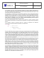
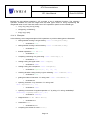
Figure 3. The model-driven architecture
As every model, the described Petri net model is composed of a number of distinct model elements. In
the context of a Petri net, these model elements correspond to the places, the transitions and the arcs
that compose the model. These different elements, as well as the way they are related, are defined in
the scope of the Petri net metamodel. In the same way a model conforms to its metamodel, there
exists a relation between the elements of a model and those of its metamodel. This relation, called
meta, associates each element of a model with the metamodel element it instantiates. Figure 2
illustrates some of the existing meta relations between elements of the Petri net model and those of
the Petri net metamodel.
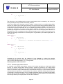
At this stage, it must be recalled that, before being a metamodel, a metamodel is a model. This implies
for it to conform to its own metamodel. To this end, the model-driven architecture defines a third
modelling level which corresponds to the metametamodel, as illustrated in Figure 3.
A metametamodel aims to introduce the semantics that are required to specify metamodels. As a
model with its metamodel, a metamodel conforms to the metametamodel. Note that a metametamodel
is usually self-defined, which means that it can be specified by means of its own semantics. In such a
case, a metametamodel conforms to itself.
Several metametamodel technologies are available. The ATL transformation engine currently provides
support for two of these existing technologies: the Meta Object Facilities (MOF 1.4) [1] defined by the
OMG and the Ecore metametamodel [4] defined by the Eclipse Modelling Framework (EMF) [5]. This
means that ATL is able to handle metamodels that have been specified according to either the MOF or
the Ecore semantics.
2.2
Model Transformation
In the scope of model-driven engineering, model transformation aims to provide a mean to specify the
way to produce target models from a number of source models. For this purpose, it should enable
developers to define the way source model elements must be matched and navigated in order to
initialize the target model elements.
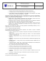
Formally, a simple model transformation has to define the way for generating a model Mb, conforming
to a metamodel MMb, from a model Ma conforming to a metamodel MMa. As previously highlighted, a
major feature in model engineering is to consider, as far as possible, all handled items as models. The
model transformation itself therefore has to be defined as a model. This transformation model has to
conform to a transformation metamodel that defines the model transformation semantics. As other
Page 3
ATL Documentations
ATL User Manual
Date 21/03/2006
metamodels, the transformation metamodel has, in turn, to conform to the considered
metametamodel.
MMM
conformsTo
conformsTo
conformsTo
MMt
MMa
MMb
conformsTo
conformsTo
conformsTo
Mt
Ma
Mb
Transformation
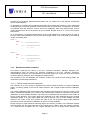
Figure 4. An overview of model transformation
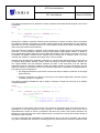
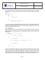
Figure 4 summarizes the full model transformation process. A model Ma, conforming to a metamodel
MMa, is here transformed into a model Mb that conforms to a metamodel MMb. The transformation is
defined by the model transformation model Mt which itself conforms to a model transformation
metamodel MMt. This last metamodel, along with the MMa and MMb metamodels, has to conform to a
metametamodel MMM (such as MOF or Ecore).
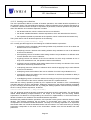
ATL is a model transformation language that enables to specify how one (or more) target model can
be produced from a set of source models. In other word, ATL introduces a set of concepts that make it
possible to describe model transformations.
Ecore
conformsTo
conformsTo
conformsTo
ATL
MMAuthor
MMPerson
conformsTo
conformsTo
conformsTo
Author2Person
Author
Person
Transformation
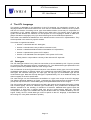
Figure 5. Overview of the Author to Person ATL transformation
Figure 5 provides an overview of the ATL transformation (Author2Person) that enables to generate a
Person model, conforming to the metamodel MMPerson, from an Author model that conforms to the
metamodel MMAuthor. The designed transformation, which is expressed by means of the ATL
language, conforms to the ATL metamodel. In this example, the three metamodels (MMAuthor,
MMPerson and ATL) are expressed using the semantics of the Ecore metametamodel.
Page 4
ATL Documentations
ATL User Manual
Date 21/03/2006
3 Overview of the Atlas Transformation Language
The ATL language offers ATL developers to design different kinds of ATL units. An ATL unit, whatever
its type, is defined in its own distinct ATL file. ATL files are characterized by the .atl extension.
As an answer to the OMG MOF [1]/QVT RFP [2], ATL mainly focus on the model to model
transformations. Such model operations can be specified by means of ATL modules. Besides
modules, the ATL transformation language also enables developers to create model to primitive data
type programs. These units are called ATL queries. The aim of a query is to compute a primitive value,
such as a string or an integer (see Section 4.1.1 for further details on the set of ATL primitive data
types), from source models. Finally, the ATL language also offers the possibility to develop
independent ATL libraries that can be imported from the different types of ATL units, including libraries
themselves. This provides a convenient way to factorize ATL code that is used in multiple ATL units.
Note that the three ATL unit kinds same the share .atl extension.
These different ATL units are detailed in the following subsections. This section explains what each
kind of unit should be used for, and provides an overview of the content of these different units.
3.1
ATL module
An ATL module corresponds to a model to model transformation. This kind of ATL unit enables ATL
developers to specify the way to produce a set of target models from a set of source models. Both
source and target models of an ATL module must be “typed” by their respective metamodels.
Moreover, an ATL module accepts a fixed number of models as input, and returns a fixed number of
target models. As a consequence, an ATL module can not generate an unknown number of similar
target models (e.g. models that conform to a same metamodel).
Section 3.1.1 details the structure of an ATL module. Section 3.1.2 presents the two available
execution modes for ATL modules. Finally, the execution semantics of the ATL module are briefly
introduced in Section 3.1.3
3.1.1
Structure of an ATL module
An ATL module defines a model to model transformation. It is composed of the following elements:
• A header section that defines some attributes that are relative to the transformation module;
• An optional import section that enables to import some existing ATL libraries (see Section
3.3);
• A set of helpers that can be viewed as an ATL equivalent to Java methods;
• A set of rules that defines the way target models are generated from source ones.
Helpers and rules do not belong to specific sections in an ATL transformation. They may be declared
in any order with respect to certain conditions (see Section 4.4 for further details). These four distinct
element types are now detailed in the following subsections.
3.1.1.1 Header section
The header section defines the name of the transformation module and the name of the variables
corresponding to the source and target models. It also encodes the execution mode of the module.
The syntax for the header section is defined as follows:
module module_name;
create output_models [from|refines] input_models;
Page 5
ATL Documentations
ATL User Manual
Date 21/03/2006
The keyword module introduces the name of the module. Note that the name of the ATL file containing
the code of the module has to correspond to the name of this module. For instance, a ModelA2ModelB
transformation module has to be defined into the ModelA2ModelB.atl file.
The target models declaration is introduced by the create keyword, whereas the source models are
introduced either by the keyword from (in normal mode) or refines (in case of refining transformation).
The declaration of a model, either a source input or a target one, must conform the scheme
model_name : metamodel_name. It is possible to declare more than one input or output model by
simply separating the declared models by a coma. Note that the name of the declared models will be
used to identity them. As a consequence, each declared model name has to be unique within the set
of declared models (both input and output ones).
The following ATL source code represents the header of the Book2Publication.atl file, e.g. the ATL
header for the transformation from the Book to the Publication metamodel [6]:
module Book2Publication;
create OUT : Publication from IN : Book;
Example with several models
3.1.1.2 Import section
The optional import section enables to declare which ATL libraries (see Section 3.3) have to be
imported. The declaration of an ATL library is achieved as follows:
uses extensionless_library_file_name;
For instance, to import the strings library, one would write:
uses strings;
Note that it is possible to declare several distinct libraries by using several successive uses
instructions.
3.1.1.3 Helpers
ATL helpers can be viewed as the ATL equivalent to Java methods. They make it possible to define
factorized ATL code that can be called from different points of an ATL transformation.
An ATL helper is defined by the following elements:
• a name (which corresponds to the name of the method);
• a context type. The context type defines the context in which this attribute is defined (in the
same way a method is defined in the context of given class in object-programming);
• a return value type. Note that, in ATL, each helper must have a return value;
• an ATL expression that represents the code of the ATL helper;
• an optional set of parameters, in which a parameter is identified by a couple (parameter
name, parameter type).
As an example, it is possible to consider a helper that returns the maximum of two integer values: the
contextual integer and an additional integer value which is passed as parameter. The declaration of
such a helper will look like (detail of the helper code is not interesting at this stage, please refer to
Section 4.2 for further details):
helper context Integer def : max(x : Integer) : Integer = ...;
It is also possible to declare a helper that accepts no parameter. This is, for instance, the case for a
helper that just multiplies an integer value by two:
helper context Integer def : double() : Integer = self * 2;
Page 6
ATL Documentations
ATL User Manual
Date 21/03/2006
In some cases, it may be interesting to be able to declare an ATL helper without any particular context.
This is not possible in ATL since each helper must be associated with a given context. However, the
ATL language allows ATL developers to declare helpers within a default context (which corresponds to
the ATL module). This is achieved by simply omitting the context part of the helper definition. It is
possible, by this mean, to provide a new version of the max helper defined above:
helper def : max(x1 : Integer, x2 : Integer) : Integer = ...;
Note that several helpers may have the same name in a single transformation. However, helpers with
a same name must have distinct signatures to be distinguishable by the ATL engine (see Section 4.4
for further details).
The ATL language also makes it possible to define attributes. An attribute helper is a specific kind of
helper that accepts no parameters, and that is defined either in the context of the ATL module or of a
model element. In the remaining of the present document, the term attribute will be specifically used to
refer to attribute helpers, whereas the generic term of helper will refer to a functional helper.
Thus, the attribute version of the double helper defined above will be declared as follows:
helper context Integer def : double : Integer = self * 2;
Declaring a functional helper with no parameter or an attribute may appear to be equivalent. It is
therefore equivalent from a functional point of view. However, there exists a significant difference
between these two approaches when considering the execution semantics. Indeed, compared to the
result of a functional helper which is calculated each time the helper is called, the return value of an
ATL attribute is computed only once when the value is required for the first time. As a consequence,
declaring an ATL attribute is more efficient than defining an ATL helper that will be executed as many
times as it is called.
Note that the ATL attributes that are defined in the context of the ATL module are initialized (during the
initialization phase, see Section 3.1.3.1 for further details) in the order they have been declared in the
ATL file. This implies that the order of declaration of this kind of attribute is of some importance: an
attribute defined in the context of the ATL module has to be declared after the other ATL module
attributes it depends on for its initialization. A wrong order in the declaration of the ATL module
attributes will raise an error during the initialization phase of the ATL program execution.
3.1.1.4 Rules
In ATL, there exist two different kinds of rules that correspond to the two different programming modes
provided by ATL (e.g. declarative and imperative programming): the matched rules (declarative
programming) and the called rules (imperative programming).
Matched rules. The matched rules constitute the core of an ATL declarative transformation since they
make it possible to specify 1) for which kinds of source elements target elements must be generated,
and 2) the way the generated target elements have to be initialized. A matched rule is identified by its
name. It matches a given type of source model element, and generates one or more kinds of target
model elements. The rule specifies the way generated target model elements must be initialized from
each matched source model element.
A matched rule is introduced by the keyword rule. It is composed of two mandatory (the source and
the target patterns) and two optional (the local variables and the imperative) sections. When defined,
the local variable section is introduced by the keyword using. It enables to locally declare and initialize
a number of local variables (that will only be visible in the scope of the current rule).
The source pattern of a matched rule is defined after the keyword from. It enables to specify a model
element variable that corresponds to the type of source elements the rule has to match. This type
corresponds to an entity of a source metamodel of the transformation. This means that the rule will
generate target elements for each source model element that conforms to this matching type. In many
cases, the developer will be interested in matching only a subset of the source elements that conform
Page 7
ATL Documentations
ATL User Manual
Date 21/03/2006
to the matching type. This is simply achieved by specifying an optional condition (expressed as an
ATL expression, see Section 4.2 for further details) within the rule source pattern. By this mean, the
rule will only generate target elements for the source model elements that both conform to the
matching type and verify the specified condition.
The target pattern of a matched rule is introduced by the keyword to. It aims to specify the elements to
be generated when the source pattern of the rule is matched, and how these generated elements are
initialized. Thus, the target pattern of a matched rule specifies a distinct target pattern element for
each target model element the rule has to generate when its source pattern is matched. A target
pattern element corresponds to a model element variable declaration associated with its
corresponding set of initialization bindings. This model element variable declaration has to correspond
to an entity of the target metamodels of the transformation.
Finally, the optional imperative section, introduced by the keyword do, makes it possible to specify
some imperative code that will be executed after the initialization of the target elements generated by
the rule.
As an example, consider the following simple ATL matched rule (MMAuthor and MMPerson
metamodels are respectively detailed in Appendix A and Appendix B):
rule Author {
from
a : MMAuthor!Author
to
p : MMPerson!Person (
name <- a.name,
surname <- a.surname
)
}
This rule, called Author, aims to transform Author source model elements (from the MMAuthor source
model) to Person target model elements in the MMPerson target model. This rule only contains the
mandatory source and target patterns. The source pattern defines no filter, which means that all
Author classes of the source MMAuthor model will be matched by the rule. The rule target pattern
contains a single simple target pattern element (called p). This target pattern element aims to allocate
a Person class of the MMPerson target model for each source model element matched by the source
pattern. The features of the generated model element are initialized with the corresponding features of
the matched source model element.
Note that a source model element of an ATL transformation should not be matched by more than one
ATL matched rule. This implies the source pattern of matched rules to be designed carefully in order to
respect this constraint. Moreover, an ATL matched rule can not generate ATL primitive type values.
Called rules. The called rules provide ATL developers with convenient imperative programming
facilities. Called rules can be seen as a particular type of helpers: they have to be explicitly called to be
executed and they can accept parameters. However, as opposed to helpers, called rules can generate
target model elements as matched rules do. A called rule has to be called from an imperative code
section, either from a match rule or another called rule.
As a matched rule, a called rule is introduced by the keyword rule. As matched rules, called rules may
include an optional local variables section. However, since it does not have to match source model
elements, a called rule does not include a source pattern. Moreover, its target pattern, which makes it
possible to generate target model elements, is also optional. Note that, since the called rule does not
match any source model element, the initialization of the target model elements that are generated by
the target pattern has to be based on a combination of local variables, parameters and module
attributes. The target pattern of a called rule is defined in the same way the target pattern of a
matched rule is. It is also introduced by the keyword to.
Page 8
ATL Documentations
ATL User Manual
Date 21/03/2006
A called rule can also have an imperative section, which is similar to the ones that can be defined
within matched rules. Note that this imperative code section is not mandatory: it is possible to specify a
called rule that only contains either a target pattern section or an imperative code section.
In order to illustrate the called rule structure, consider the following simple example:
rule NewPerson (na: String, s_na: String) {
to
p : MMPerson!Person (
name <- na
)
do {
p.surname <- s_na
}
}
This called rule, named NewPerson, aims to generate Person target model elements. The rule accepts
two parameters that correspond to the name and the surname of the Person model element that will
be created by the rule execution. The rule has both a target pattern (called p) and an imperative code
section. The target pattern allocates a Person class each time the rule is called, and initializes the
name attribute of the allocated model element. The imperative code section is executed after the
initialization of the allocated element (see Section 3.1.3.1 for further details on execution semantics).
In this example, the imperative code sets the surname attribute of the generated Person model
element to the value of the parameter s_na.
3.1.2
Module execution modes
The ATL execution engine defines two different execution modes for ATL modules. With the default
execution mode, the ATL developer has to explicitly specify the way target model elements must be
generated from source model elements.
In this scope, the design of a transformation which aims to copy its source model with only a few
modifications may prove to be very tiresome. Designing this transformation in default execution mode
therefore requires the developer to specify the rules that will generate the modified model elements,
but also all the rules that will only copy, without any modification, source to target model elements. The
refining execution mode has been designed for this kind of situation: it enables ATL developers to only
specify the modifications that have to be performed between the transformation source and target
models.
These two execution modes are described in the following subsections.
3.1.2.1 Normal execution mode
The normal execution mode is the ATL module default execution mode. It is associated with the
keyword from in the module header (see Section 3.1.1.1).
In default execution mode, the ATL developer has to specify, either by matched or called rules, the
way to generate each of the expected target model elements. This execution mode suits to most ATL
transformations where target models differ from the source ones.
3.1.2.2 Refining execution mode
The refining execution mode has been introduced to ease the programming of refining transformations
between similar source and target models. With the refining mode, ATL developers can focus on the
ATL code dedicated to the generation of modified target elements. Other model elements (e.g. those
that remain unchanged between the source and the target model) are implicitly copied from the source
to the target model by the ATL engine.
Page 9
ATL Documentations
ATL User Manual
Date 21/03/2006
The refining mode is associated with the keyword refines in then header of the ATL module (see
Section 3.1.1.1). Granularity of the refining mode is defined at the model element level. This means
that the developer will have to specify how to generate a model element as soon as the transformation
modifies one of its features (either an attribute or a reference). On the other side, the developer is not
required to specify the ATL code that corresponds to the copy of unchanged model elements. This
feature may result in important saving of ATL code, which, in the end, makes the programming of
refining ATL transformations simpler and easier.
At current time, the refining mode can only be used to transform a single source model into a single
target model. Both source and target models must conform to the same metamodel.
Note that, due to current execution semantics of the refining mode (see Section 3.1.3), some specific
precautions still have to be taken by developers. Indeed, with current implementation of the ATL
engine, to be transformed into a target model element, a source model element has to match one of
the following conditions:
• being transformed by a rule explicitly specified by the developer;
• being referred (directly or indirectly) from a transformed source model element.
This means that a source model element will not be copied into its corresponding target model
element if:
• no target model element is generated by the explicated transformation rules;
• no explicitly transformed source model element refers, directly or indirectly, this source
model element.
As a consequence, it may be useful, when designing an ATL module in refining mode, to specify
additional explicit rules in order to make sure that all source model elements are transformed into their
corresponding target model elements.
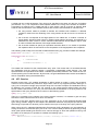
This trap is illustrated by the following example. Consider the SimpleMetamodel metamodel presented
in Figure 6: it is composed of a model element A and a model element B. Model element A has a
single feature which is a one-to-many reference to element B. Model element B has two features: an
attribute called attributeB and a zero-to-one reference to element A.
A developer may want to refine a model conforming to the SimpleMetamodel by simply modifying the
content of the feature attributeB of the model element B.
Figure 6. The SimpleMetamodel metamodel
For this purpose, an ATL transformation in refining mode, composed of the following single matched
rule may appear to be sufficient:
rule B {
from
in : SimpleMetamodel!B
to
out : SimpleMetamodel!B (
attributeB <- ...
)
}
As a result, such a transformation will produce a target model only composed of the refined B model
elements. The model elements A will not be copied by the transformation since they are neither
Page 10
ATL Documentations
ATL User Manual
Date 21/03/2006
matched by any explicitly specified transformation rule, nor referred to by the explicitly transformed
source model elements.
An approach for correcting this unexpected result may be to initialize the reference a of the matched B
model elements, so that the pointed A model elements will be transformed. This approach is however
not sufficient since the reference a has a zero-to-one multiplicity: there may therefore exist some A
model elements that will not be pointed by any B model element, and as so, will not be implicitly
transformed.
As a consequence, the explicit transformation of the model elements A is here required in order to
have the same model elements in the source and the target models. This is achieved by the following
couple of matched rules:
rule A {
from
in : SimpleMetamodel!A
to
out : SimpleMetamodel!A (
b <- in.b
)
}
rule B {
from
in : SimpleMetamodel!B
to
out : SimpleMetamodel!B (
attributeB <- ...,
a <- in.a
)
}
3.1.3
Module execution semantics
This section introduces the basics of the ATL execution semantics. Although designing ATL
transformations does not require any particular knowledge on the ATL execution semantics,
understanding the way an ATL transformation is processed by the ATL engine can prove to be helpful
in certain cases (in particular, when debugging a transformation).
The semantics of the two available ATL execution modes, the normal and the refining modes, are
introduced in the following subsections.
3.1.3.1 Default mode execution semantics
The execution of an ATL module is organized into three successive phases: a module initialization
phase, a matching phase of the source model elements, and a target model elements initialization
phase.
The module initialization step corresponds to the first phase of the execution of an ATL module. In this
phase, the attributes defined in the context of the transformation module are initialized. Note that the
initialization of these module attributes may make use of attributes that are defined in the context of
source model elements. This implies these new attributes to be also initialized during the module
initialization phase. If an entry point called rule (refer to Section 4.5.3 for further details) has been
defined in the scope of the ATL module, the code of this rule (including target model elements
generation) is executed after the initialization of the ATL module attributes.
During the source model elements matching phase, the matching condition of the declared matched
rules are tested with the model elements of the module source models. When the matching condition
of a matched rule is fulfilled, the ATL engine allocates the set of target model elements that
Page 11
ATL Documentations
ATL User Manual
Date 21/03/2006
correspond to the target pattern elements declared in the rule. Note that, at this stage, the target
model elements are simply allocated: they are initialized during the target model elements initialization
phase.
The last phase of the execution of an ATL module corresponds to the initialization of the target model
elements that have been generated during the previous step. At this stage, each allocated target
model element is initialized by executing the code of the bindings that are associated with the target
pattern element the element comes from. Note that this phase allows invocations of the resolveTemp()
operation (see Section 4.1.3) that is defined in the context of the ATL module.
The imperative code section that can be specified in the scope of a matched rule is executed once the
rule initialization step has completed. This imperative code can trigger the execution of some of the
called rules that have been defined in the scope of the ATL module.
3.1.3.2 Refining mode execution semantics
The refining execution mode introduces specific semantics for the implicit generation of copied model
elements.
An ATL module executed in refining mode follows the three successive phases of the default
execution mode. The execution of the first phase, the module initialization phase, remains unchanged
compared to the default execution mode. During the source model elements matching phase, the ATL
engine only evaluates the matching conditions of the explicitly specified matched rules. This implies
that, at this stage, the only target model elements that are allocated are those that are generated by
these explicit transformations rules.
The differences with the default execution mode appear during the execution of the initialization phase
of the target model elements. In refining mode, this phase has to deal with the initialization of the
explicitly generated target model elements, but also with the allocation and the initialization of the
target model elements that are implicitly generated.
For this purpose, each time an already allocated target model element is initialized with a reference to
a non-allocated model element, the ATL engine allocates and initializes this new target model
element. If the newly created model element also refers to another non-allocated model element, this
process is repeated recursively.
Note that with the described semantics, no target model element will be generated for a source model
element that is neither matched by an explicit rule, nor referred, directly or indirectly, by an explicitly
generated target model element.
3.2
ATL Query
An ATL query consists in a model to primitive type value transformation (refer to Section 4.1.1 for a
description of ATL supported primitive types). An ATL query can be viewed as an operation that
computes a primitive value from a set of source models. The most common use of ATL queries is the
generation of a textual output (encoded into a string value) from a set of source models. However, ATL
queries are not limited to the computation of string values and can also return a numerical or a
boolean value.
The following subsections respectively describe the structure and the execution semantics of an ATL
query.
3.2.1
Structure of an ATL query
After an optional import section (see Section 3.1.1.2), an ATL query must define a query instantiation.
A query instantiation is introduced by the keyword query and specifies the way its result must be
computed by means of an ATL expression:
query query_name = exp;
Page 12
ATL Documentations
ATL User Manual
Date 21/03/2006
Beside the query instantiation, an ATL query may include a number of helper or attribute definitions.
Note that, although an ATL query is not strictly a module, it defines its own kind of default module
context. It is therefore possible, for ATL developers, to declare helpers and attributes defined in the
context of the module in the scope of an ATL query.
3.2.2
Query execution semantics
As an ATL module, the execution of an ATL query is organized in several successive phases. The first
phase is the initialization phase. It corresponds to the initialization phase of the ATL modules (see
Section 3.1.3.1) and is dedicated to the initialization of the attributes that are defined in the context of
the ATL module.
The second phase of the execution of an ATL query is the computation phase. During this phase, the
return value of the query is calculated by executing the declarative code of the query element of the
ATL query. Note that the helpers that have been defined within the query file can be called at both the
initialization and the computation phases.
3.3
ATL Library
The last type of ATL unit is the ATL library. Developing an ATL library enables to define a set of ATL
helpers that can be called from different ATL units (modules, but also queries and libraries).
As the other kinds of ATL units, an ATL library can include an optional import section (see Section
3.1.1.2). Besides this import section, an ATL library defines a number of ATL helpers that will be made
available in the ATL units that will import the library.
Compared to an ATL module, there exists no default module element for ATL libraries. As a
consequence, it is impossible, in libraries, to declare helpers that are defined in the default context of
the module. This means that all the helpers defined within an ATL library must be explicitly associated
with a given context.
Compared to both modules and queries, an ATL library cannot be executed independently. This
currently means that a library is not associated with any initialization step at execution time (as
described in Section 3.1.3). Due to this lack of initialization step, attribute helpers cannot be defined
within an ATL library.
Page 13
ATL Documentations
ATL User Manual
Date 21/03/2006
4 The ATL Language
This section is dedicated to the description of the ATL language. As introduced in Section 3, the
language enables to define three kinds of ATL units: the ATL transformation modules, the ATL queries
and the ATL libraries. According to their type, these different kinds of units may be composed of a
combination of ATL helpers, attributes, matched and called rules. This section aims to detail the
syntax of these different ATL elements. For this purpose, the ATL language is based on OMG OCL
(Object Constraint Language) norm [7] for both its data types and its declarative expressions.
There exist a few differences between the OCL definition and the current ATL implementation. They
will be specified in this section by specific remarks.
This section is organized as follows:
• Section 4.1 describes the OCL data types;
• Section 4.2 introduces the way to define comments in OCL;
• Section 4.3 details the different kinds of declarative OCL expressions;
• Section 4.4 presents the syntax of ATL helpers;
• Section 4.5 is dedicated to the description of the syntax of ATL rules;
• Finally, Section 4.6 provides a summary of the reserved ATL keywords.
4.1
Data types
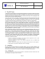
The ATL data type scheme is very close, but not similar, to the one defined by OCL. Figure 7 provides
an overview of the data type’s structure considered in ATL. The different data types presented in this
schema represent the possible instances of the OclType class.
The root element of the OclType instances structure is the abstract OclAny type, from which all other
considered types directly or indirectly inherit. ATL considers six main kinds of data types: the primitive
data types, the collection data types, the tuple type, the map type, the enumeration type and the
model element type. Note that the map data type is implemented by ATL as an additional facility, but
does not appear in the OCL specification.
The class OclType can be considered as the definition of a type in the scope of the ATL language.
The different elements appearing in Figure 7 represent the type instances that are defined by OCL
(except the map and the ATL module data types), and implemented within the ATL engine.
The OCL primitive data types correspond to the basic data types of the language (the string, boolean
and numerical types). The set of collection types introduced by OCL provides ATL developers with
different semantics for the handling of collections of elements. Additional data types include the
enumerations, a tuple and a mapping data type and the model element data type. This last
corresponds to the type of the entities that may be declared within the models handled by the ATL
engine. Finally, the ATL module data type, which is specific to the ATL language, is associated with
the running ATL units (either modules or queries).
Page 14
ATL Documentations
ATL User Manual
Date 21/03/2006
OclAny
Tuple
Primitive
Boolean
Numeric
OclModelElement
String
Collection
EnumLiteral
ATL Module
Integer
Set
Sequence
OrderedSet
Map
Bag
Real
Figure 7. The ATL data types metamodel
Before going further in the description of these data types, it must be noted that each OCL expression,
including the operations associated with each kind of data type (that are presented along with their
respective data type), is defined in the context of an instance of a specific type. In ATL as in OCL, the
reserved keyword self is used to refer to this contextual instance.
Before detailing the different available data types, Section 4.1.1 describes the set of operations that
are defined for the class OclType itself. Then, Section 4.1.2 presents the operations that are common
to all these data types (e.g. those that are defined in the context of the OclAny type). Section 4.1.3
deals with the ATL Module data type. Section 4.1.4 is dedicated to the different primitive data types
supported by ATL. Section 4.1.5 then describes the semantics of the available collection data types.
Section 4.1.6, Section 4.1.7 and Section 4.1.8 respectively deal with the enumeration, the tuple and
the map data types. Finally, Section 4.1.9 presents the model element data type.
4.1.1
OclType operations
The class OclType corresponds to the definition of the type instances specified by OCL. It is
associated with a specific OCL operation: allInstances(). This operation, which accepts no parameter,
returns a set containing all the currently existing instances of the type self.
The ATL implementation provides an additional operation that enables to get all the instances of a
given type that belong to a given metamodel. Thus, the allInstancesFrom(metamodel : String)
operation returns a set containing the instances of type self that are defined within the model namely
identified by metamodel.
4.1.2
OclAny operations
This section describes a set of operations that are common to all existing data types. The syntax used
to call an operation from a variable in ATL follows the classical dot notation:
self.operation_name(parameters)
ATL currently provides support for the following OCL-defined operations:
• comparison operators: =, <>;
Page 15
ATL Documentations
ATL User Manual
Date 21/03/2006
• oclIsUndefined() returns a boolean value stating whether self is undefined;
• oclIsKindOf(t : oclType) returns a boolean value stating whether self is an either an instance
of t or of one of its subtypes;
• oclIsTypeOf(t : oclType) returns a boolean value stating whether self is an instance of t.
The operations oclIsNew() and oclAsType() defined by OCL are currently not supported by the ATL
engine. ATL however implements a number of additional operations:
• toString() returns a string representation of self. Note that the operation may return irrelevant
string values for a few remaining types;
• oclType() returns the oclType of self;
• asSequence(), asSet(), asBag() respectively return a sequence, a set or a bag containing
self. These operations are redefined for the collection types;
• output(s : String) writes the string s to the Eclipse console. Since the operation has no return
value, it shall only be used in ATL imperative blocks;
• debug(s : String) returns the self value and writes the “s : self_value” string to the eclipse
console;
• refSetValue(name : String, val : oclAny) is a reflective operation that enables to set the self
feature identified by name to value val. It returns self;
• refGetValue(name : String) is a reflective operation that returns the value of the self feature
identified by name;
• refImmediateComposite() is a reflective operation that returns the immediate composite (e.g.
the immediate container) of self;
• refInvokeOperation(opName : String, args : Sequence) is a reflective operation that enables
to invoke the self operation named opName with the sequence of parameter contained by
args.
4.1.3
The ATL Module data type
The ATL Module data type is specific to the ATL language. This internal data type aims to represent
the ATL unit (either a module or a query) that is currently run by the ATL engine. There exists a single
instance of this data type, and developers can refer to it (in their ATL code) using the variable
thisModule. The thisModule variable makes it possible to access the helpers (see Section 4.4.1) and
the attributes (see Section 4.4.2) that have been declared in the context of the ATL module.
The ATL Module data type also provides the resolveTemp operation. This specific operation makes it
possible to point, from an ATL rule, to any of the target model elements (including non-default ones)
that will be generated from a given source model element by an ATL matched rule.
The operation resolveTemp has the following declaration: resolveTemp(var, target_pattern_name).
The parameter var corresponds to an ATL variable that contains the source model element from which
the searched target model element is produced. The parameter target_pattern_name is a string value
that encodes the name of the target pattern element (see Section 4.5.2) that maps the provided
source model element (contained by var) into the searched target model element.
Note that, as it is defined in the scope of the ATL module, this operation must be called from the
variable thisModule. The resolveTemp operation must not be called before the completion of the
matching phase (see Section 3.1.3). This means that the operation can be called from:
• the target pattern and do sections of any matched rule;
Page 16
ATL Documentations
ATL User Manual
Date 21/03/2006
• the target pattern and do sections of a called rule, provided that this called rule is executed
after the matching phase (e.g. is not called from a transformation entrypoint).
ATL developers may note that the operation call does not specify the matched rule from which the
generated target model element comes from. However, as explained in Section 3.1.1.4, a source
model element should not be matched by more than one matched rule. As a consequence, the
concerned matched rule can be derived from the specified source model element.
4.1.4
Primitive data types
OCL defines four basic primitive data types:
•
the Boolean data type, for which possible values are true or false;
•
the Integer data type which is associated with the integer numerical values (1, -5, 2, 34,
26524, ...);
•
the Real data type which is associated with the floating numerical values (1.5, 3.14, ...);
•
the String data type ('To be or not to be', …). A string is defined between ''. The
escape character ‘\’ enables to include ' characters within handled string variables. Note
that, in OCL:
o
a character is encoded as a one-character string;
o
the characters composing a string are numbered from 1 to the size of the string.
According to the considered data type (string, numerical values and boolean values), OCL defines a
number of specific operations. They are detailed in the following sections along with some additional
functions provided by the ATL engine.
4.1.4.1 Boolean data type operations
The set of OCL operations defined for the boolean data type is the following:
•
logical operators: and, or, xor, not;
•
implies(b : Boolean)
returns true otherwise.
returns
false
if
self
is
true
and
b
is
false,
and
4.1.4.2 String data type operations
OCL defines the following operations for the string data type:
•
size() returns the number of characters contained by the string self;
•
concat(s : String) returns a string in which the specified string s is concatenated to the end
of self;
•
substring(lower : Integer, upper : Integer) returns the substring of self starting from
character lower to character upper;
•
toInteger() and toReal().
Besides the OCL-defined operations, ATL implements a number of additional operations for the string
data type:
• comparison operators: <, >, =>, =<;
• the string concatenation operator (+) can be used as a shortcut for the string concat()
function;
Page 17
ATL Documentations
ATL User Manual
Date 21/03/2006
• toUpper(), toLower() respectively return an upper/lower case copy of self;
• toSequence() returns the sequence of characters (e.g. of one-character strings)
corresponding to self;
• trim() returns a copy of self with leading and trailing white spaces (‘ ’, ‘\t’, ‘\n’, ‘\f’, ‘\r’) omitted;
• startsWith(s : String), endsWith(s : String) return a boolean value respectively stating
whether self starts/ends with s;
• indexOf(s : String), lastIndexOf(s : String) respectively return the index (an integer value)
within self of the first/last occurrence of the specified substring s;
• split(regex : String) splits the self string around matches of the regular expression regex.
Specification of regular expression must follow the definition of Java regular expressions [8].
Result is returned as a sequence of strings;
• replaceAll(c1 : String, c2 : String) returns a copy of self in which each occurrence of
character c1 is replaced with the character c2. Note that both c1 and c2 are specified as
OCL strings. However the function only considers the first character of each of the provided
strings;
• regexReplaceAll(regex : String, replacement : String) returns a copy of self in which each
substring of this string that matches the given regular expression regex is replaced with the
given replacement. Specification of regular expression must follow the definition of Java
regular expressions [8].
As a last point, ATL currently defines two additional functions that make it possible to write strings to
outputs. These functions are useful for redirecting the result of ATL queries, but they may also be used
for debugging purposes:
• writeTo(fileName : String) enables to write the self string into the file identified by the string
fileName. Note that this string may encode either a full or a relative path to the file. In the last
case, the path is relative to the \eclipse directory from which the ATL tool kit is run. If the
identified file already exists, the function writes the new content over this existing file;
• println() writes the self string onto the default output, that is the Eclipse console (see Section
5.2.1.7).
Note that these two functions are provided as temporary solutions as the ATL toolkit does still not
provide any integrated solution for the redirection of the result of ATL queries. They are likely to be
removed from future releases of the ATL tool suite.
4.1.4.3 Numerical data type operations
The following OCL operations are defined for both OCL numerical data types (integer and real):
•
comparison operators: <, >, =>, =<;
•
binary operators: *, +, -, /, div(), max(), min();
•
unary operator: abs().
Note that the – unary operator defined by OCL (that returns the negative value of self) is not
implemented in current version of ATL. As a consequence, a –x negative numerical value has to be
declared as the result of a call to the – binary operator: 0-x.
OCL also defines some operations that are specific to the integer and the real data types:
•
integer operation: mod();
•
real operations: floor(), round().
Page 18
ATL Documentations
ATL User Manual
Date 21/03/2006
Besides the OCL-defined operations, ATL provides a set of additional functions. The toString()
operation, available for both the integer and real data types returns a string representing the
integer/real value of self. There also exist a set of ATL operations specific to the real data type:
•
cos(), sin(), tan(), acos(), asin();
•
toDegrees(), toRadians();
•
exp(), log(), sqrt().
4.1.4.4 Examples
In the following, some usage examples of OCL operations on primitive data types are illustrated:
•
testing whether a string is of type OclAny: 'test'.oclIsTypeOf(OclAny)
o
•
testing whether a string is of kind OclAny: 'test'.oclIsKindOf(OclAny)
o
•
evaluates to false
getting last index of character “t” in string “test”: 'test'.lastIndexOf('t')
o
•
evaluates to Sequence{'t', 'e', 's', 't'}
checking whether a string ends by a given substring: 'test'.endsWith('ast')
o
•
evaluates to 'TEST'
casting a string into a sequence: 'test'.toSequence()
o
•
evaluates to 'es'
casting a string into upper case: 'test'.toUpper()
o
•
evaluates to true
computing a substring of a given string: 'test'.substring(2, 3)
o
•
evaluates to true
boolean operations: true or false
o
•
evaluates to false
evaluates to 4
replacing character “t” by character “o” in string “test”:
'test'.replaceAll('t', 'o')
o
•
evaluates to 'oeso'
replacing occurrences of regular expression “a*” by string “A” in string “aaabaftaap”:
'aaabaftaap'.regexReplaceAll('a*', 'A')
o
•
integer division: 23 div 2 or 23.”div”(2)
o
•
evaluates to 11
real division: 23/2
o
•
evaluates to 'AbAftAp'
evaluates to 11.5
computing the cosines of a real: 23.cos()
Page 19
ATL Documentations
ATL User Manual
4.1.5
Date 21/03/2006
Collection data types
OCL defines a number of collection data types that provide developers with different ways to handle
collections of elements. The provided collection types are Set, OrderedSet, Bag and Sequence.
Collection is the common abstract superclass of these different types of collections.
The existing collection classes have the following characteristics:
•
Set is a collection without duplicates. Set has no order;
•
OrderedSet is a collection without duplicates. OrderedSet is ordered;
•
Bag is a collection in which duplicates are allowed. Bag has no order;
•
Sequence is a collection in which duplicates are allowed. Sequence is ordered.
A collection can be seen as a template data type. This means that the declaration of a collection data
type has to include the type of the elements that will be contained by the type instances. Whatever the
type of the contained elements, the declaration of a collection data type has to conform to the
following scheme:
collection_type(element_datatype)
The supported collection data types are Set, OrderedSet, Sequence and Bag. The element data type
can be any supported oclType, including another collection type.
The definition of a collection variable is achieved as follows:
collection_type{elements}
Please note that the brackets used in the type definition must here be replaced by curly brackets.
Examples of collection type definitions and instantiations can be found in Section 4.1.5.7.
OCL defines a number of operations that are common to these different collection types. These
common operations are described in Section 4.1.5.1. Section 4.1.5.2, Section 4.1.5.3, Section 4.1.5.4
and Section 4.1.5.5 respectively detail the operations specific to the sequence, set, ordered set and
bag data types. Section 4.1.5.6 describes the collection iteration facilities introduced by OCL. Finally,
Section 4.1.5.7 provides a number of examples illustrating the use of collection elements as well as
the invocation of collection operations.
4.1.5.1 Operations on collections
ATL provides a large number of operations in the context of the different supported collection types.
Note that there exists a specific syntax for invoking an operation onto a collection type:
self->operation_name(parameters)
The different kinds of existing OCL collections share a number of common operations:
•
size() returns the number of elements in the collection self;
•
includes(o : oclAny) returns a boolean stating whether the object o is part of the collection
self;
•
excludes(o : oclAny) returns a boolean stating whether the object o is not part of the
collection self;
•
count(o : oclAny) returns the number of times the object o occurs in the collection self;
•
includesAll(c : Collection) returns a boolean stating whether all the objects contained by
the collection c are part of the self collection;
•
excludesAll(c : Collection) returns a boolean stating whether none of the objects contained
by the collection c are part of the self collection;
Page 20
ATL Documentations
ATL User Manual
Date 21/03/2006
•
isEmpty() returns a boolean stating whether the collection self is empty;
•
notEmpty() returns a boolean stating whether the collection self is not empty;
•
sum() returns a value that corresponds to the addition of all elements in self. These
elements must be of a type that support the + operation.
Note that the product() operation defined by OCL is unsupported by the current ATL implementation.
However, ATL defines three additional operations in the context of a collection (OCL defines similar
operations in the context of each collection type):
• asBag() returns a bag containing the elements of the self collection. Order is lost from a
sequence or an ordered set. Has no effect in the context of a bag;
• asSequence() returns a sequence containing the elements of the self collection. Introduces
an order from a bag or a set. Has no effect in the context of a sequence;
• asSet() returns a set containing the elements of the self collection. Order is lost from a
sequence or an ordered set. Duplicates are removed from a bag or a sequence. Has no
effect in the context of a set.
Note that, in the current ATL version, the casting operation asOrderedSet() defined by OCL is
implemented for none of the collection types.
4.1.5.2 Sequence data type operations
The sequence type supports all the collection operations. OCL defines a number of additional
operations that are specific to sequences:
•
union(c : Collection) returns a sequence composed of all elements of self followed by the
elements of c;
•
flatten() returns a sequence directly containing the children of the nested subordinate
collections contained by self;
•
append(o : oclAny) returns a copy of self with the element o added at the end of the
sequence;
•
prepend(o : oclAny) returns a copy of self with the element o added at the beginning of the
sequence;
•
insertAt(n : Integer, o : oclAny), returns a copy of self with the element o added at rank n of
the sequence;
•
subSequence(lower : Integer, upper : Integer) returns a subsequence of self starting from
rank lower to rank upper (both bounds being included);
•
at(n : Integer) returns the element located at rank n in self;
•
indexOf(o : oclAny) returns the rank of first occurrence of o in self;
•
first() returns the first element of self (oclUndefined if self is empty);
•
last() returns the last element of self (oclUndefined if self is empty);
•
including(o : oclAny) returns a copy of self with the element o added at the end of the
sequence;
•
excluding(o : oclAny) returns a copy of self with all occurrences of element o removed.
4.1.5.3 Set data type operations
Set supports all collection operations and some specific ones:
Page 21
ATL Documentations
ATL User Manual
Date 21/03/2006
•
union(c : Collection) returns a set composed of the elements of self and the elements of c
with duplicates removed (they may appear within c, and between c and self elements);
•
intersection(c : Collection) returns a set composed of the elements that appear both in self
and c;
•
operator – (s : Set) returns a set composed of the elements of self that are not in s;
•
including(o : oclAny), returns a copy of self with the element o if not already present in self;
•
excluding(o : oclAny), returns a copy of self with the element o removed from the set;
•
symetricDifference(s : Set) returns a set composed of the elements that are in self or s, but
not in both.
Note that the flatten() operation defined by OCL is not implemented in the current version of ATL.
4.1.5.4 OrderedSet data type operations
The sequence type supports all the collection operations. OCL defines a number of additional
operations that are specific to ordered sets:
•
append(o : oclAny) returns a copy of self with the element o added at the end of the
ordered set if it does not already appear in self;
•
prepend(o : oclAny) returns a copy of self with the element o added at the beginning of the
ordered set if it does not already appear in self;
•
insertAt(n : Integer, o : oclAny), returns a copy of self with the element o added at rank n of
the ordered set if it does not already appear in self;
•
subOrderedSet (lower : Integer, upper : Integer) returns a subsequence of self starting
from rank lower to rank upper (both bounds being included);
•
at(n : Integer) returns the element located at rank n in self;
•
indexOf(o : oclAny) returns the rank of first occurrence of o in self;
•
first() returns the first element of self (oclUndefined if self is empty);
•
last() returns the last element of self (oclUndefined if self is empty).
Besides this set of operations specified by OCL, ATL implements the following additional functions:
•
union(c : Collection) returns an ordered set composed of the elements of self followed by
the elements of c with duplicates removed (they may appear within c, and between c and
self elements);
•
flatten() returns an ordered set directly containing the children of the nested subordinate
collections contained by self;
•
including(o : oclAny) returns a copy of self with the element o added at the end of the
ordered set if it does not already appear in self;
•
excluding(o : oclAny) returns a copy of self with the o removed.
4.1.5.5 Bag data type operations
The bag operations defined by the OCL specification are not available with the current ATL
implementation.
Page 22
ATL Documentations
ATL User Manual
Date 21/03/2006
4.1.5.6 Iterating over collections
The OCL specification defines a number of iterative operations, also called iterative expressions, on
the collection types. The main difference between a classical operation and an iterative expression on
a collection is that the iterator accepts an expression as parameter, whereas operations only deal with
data. The definition of an iterative expression includes:
• the iterated collection, which is referred as the source collection;
• the iterator variables declared in iterative expressions, which are referred as the iterators;
• the expression passed as parameter to the operation, which is referred as the iterator body.
The syntax used to call an iterative expression is the following:
source->operation_name(iterators | body)
ATL currently provides support for the following set of defined iterative expressions:
• exists(body) returns a boolean value stating whether body evaluates to true for at least one
element of the source collection;
• forAll(body) returns a boolean value stating whether body evaluates to true for all elements
of the source collection;
• isUnique(body) returns a boolean value stating whether body evaluates to a different value
for each element of the source collection;
• any(body) returns one element of the source collection for which body evaluates to true. If
body never evaluates to true, the operation returns OclUndefined;
• one(body) returns a boolean value stating whether there is exactly one element of the source
collection for which body evaluates to true;
• collect(body) returns a collection of elements which results in applying body to each element
of the source collection;
• select(body) returns the subset of the source collection for which body evaluates to true;
• reject(body) returns the subset of the source collection for which body evaluates to false (is
equivalent to select(not body));
• sortedBy(body) returns a collection ordered according to body from the lowest to the highest
value. Elements of the source collection must have the < operator defined.
Note that the collect() operation provided by ATL implements the semantics of the collectNested()
operation defined in the OCL specification. Getting the semantics of the collect() operation as defined
by OCL can simply be achieved with ATL by calling the flatten() operation onto the result provided by
the ATL collect() iterative expression, as follows:
source->collect(iterator | body)->flatten()
The ATL language introduces another constraint compared to the OCL specification. The specification
indeed allows declaring multiple iterators in the scope of the exists() and the forAll() iterative
expressions. This feature is not supported by the current ATL implementation, in which the number of
iterator is limited to one, whatever the considered iterative expression.
Besides these predefined iterative operations, OCL specifies a more generic collection iterator, named
iterate(). This iterative expression has an iterator, an accumulator and a body. The accumulator
corresponds to an initialized variable declaration. The body of an iterate() expression is an expression
that should make use of both the declared iterator and accumulator. The value returned by an iterate()
expression corresponds to the value of the accumulator variable once the last iteration has been
performed.
Page 23
ATL Documentations
ATL User Manual
Date 21/03/2006
An iterative expression is defined with the following syntax:
source->iterate(iterator, variable_declaration = init_exp |
body
)
4.1.5.7 Examples
In the following, some operations on collections are illustrated:
• declaring the sequence of integer type: Sequence(Integer)
• specifying a sequence of integers: Sequence{1, 2, 3}
• declaring the set of sequences of string type: Set(Sequence(String))
• specifying a set of sequences of strings:
Set{Sequence{'monday'}, Sequence{'march', 'april', 'may'}}
• testing whether a bag is empty: Bag{1, 2, 3}->isEmpty()
o
evaluates to false
• testing whether a set contains an element: Set{1, 2, 3}->includes(1)
o
evaluates to true
• testing whether a set contains all the elements of another set:
Set{1, 2, 3}->includesAll(Set{3, 2})
o
evaluates to true
• getting the size of a sequence: Sequence{1, 2, 3}->size()
o
evaluates to 3
o
note that Set{3, 3, 3}->size() evaluates to 1 since the set data type eliminates
duplicates
• getting the first element of an ordered set sequence: OrderedSet{1, 2, 3}->first()
o
evaluates to 1
• computing the union of two sequences: Sequence{1, 2, 3}->union(Sequence{7, 3, 5})
o
evaluates to Sequence{1, 2, 3, 7, 3, 5}
• computing the union of two sets: Set{1, 2, 3}->union(Set{7, 3, 5})
o
evaluates to Set{1, 2, 3, 7}
• flattening a sequence of sequences:
Sequence{Sequence{1, 2}, Sequence{3, 5, 2}, Sequence{1}}->flatten()
o
evaluates to Sequence{1, 2, 3, 5, 2, 1}
• computing a subsequence of a sequence:
Sequence{Sequence{1, 2}, Sequence{3, 5, 2}, Sequence{1}}->subSequence(2, 3)
o
evaluates to Sequence{ Sequence{3, 5, 2}, Sequence{1}}
• inserting an element at a given position into a sequence:
Sequence{5, 15, 20}->insertAt(2, 10)
Page 24
ATL Documentations
ATL User Manual
o
Date 21/03/2006
evaluates to Sequence{5, 10, 15, 20}
• computing the intersection of two sets: Set{1, 2, 3}->intersection(Set{7, 3, 5})
o
evaluates to Set{3}
• computing the symmetric difference of two sets:
Set{1, 2, 3}->symetricDifference(Set{7, 3, 5})
o
evaluates to Set{1, 2, 7, 5}
• selecting all elements of a sequence that are smaller or equal to 3:
Sequence{1, 2, 3, 4, 5, 6}->select(i | i <= 3)
o
evaluates to Set{1, 2, 3}
• collecting the names of all MOF classes:
MOF!Class.allInstances()->collect(e | e.name)
• checking whether all the numbers in a sequence are greater than 2:
Sequence{12, 13, 12}->forAll(i | i > 2)
o
evalutes to true
• checking whether there is only one element of the sequence that is greater that 2:
Sequence{12, 13, 12}->one(i | i > 2)
o
evalutes to false
• checking whether there exists a number in the sequence that is greater than 2:
Sequence{12, 13, 12}->exists(i | i > 2)
o
evaluates to true
• computing the sum of the positive integer of a sequence using the iterate instruction:
Sequence{8, -1, 2, 2, -3}->iterate(e; res : Integer = 0 |
if e > 0
then
res + e
else
res
endif
)
4.1.6
o
evaluates to 12;
o
is equivalent to Sequence{8, -1, 2, 2, -3}->select(e | e > 0)->sum()
Enumeration data types
An enumeration is an OclType. It has a name just as any other data type. However, compared to the
data presented up to now, the enumerations have to be defined within the source and target
metamodels of a transformation.
With the OCL specification, referring to an enumeration literal (e.g. an enumeration defined value) is
achieved by specifying the enumeration type (e.g. the name of the enumeration), followed by two
double-points and the enumeration value. Consider, as an example, an enumeration named Gender
that defines two possible values, male and female. Accessing to the female value of this enumeration
type in OCL is achieved as follows: Gender::female.
Page 25
ATL Documentations
ATL User Manual
Date 21/03/2006
The current ATL implementation differs from the OCL specification. Access to enumeration values is
simply achieved by prefixing the enumeration by a sharp character (the enumeration type is no more
required): #female.
The enumeration data type is associated with no specific operation.
4.1.7
Tuple data type
The tuple data type enables to compose several values into a single variable. A tuple consists into a
number of named parts that may each have a distinct type. Note that a tuple type is not named. As a
consequence, a declared tuple type has to be identified by its full declaration each time it is required.
Each part of a tuple type is associated with an OclType and is identified by a unique name. The
declaration of a tuple data type must conform to the following syntax:
TupleType(var_name1 : var_type1, ..., var_namen : var_typen)
Note that the order in which the different parts are declared is not significant. As an example, it is
possible to consider the declaration of a tuple type associating an Author model element from the
MMAuthor metamodel (see Appendix A) with a couple of strings encoding the title of a book and the
name of the editor of this book:
TupleType(a : MMAuthor!Author, title : String, editor : String)
The instantiation of a declared tuple variable has to respect the following syntax:
Tuple{var_name1 [: var_type1]? = init_exp1, ..., var_namen [: var_typen]? =
init_expn}
When declaring a tuple instance, the types of the tuple parts can be omitted. As a consequence, the
two following tuple instantiations corresponding to the tuple type defined above are equivalent:
Tuple{editor : String = 'ATL Eds.', title : String = 'ATL Manual', a :
MMAuthor!Author = anAuthor}
Tuple{title = 'ATL Manual', a = anAuthor, editor = 'ATL Eds.'}
As for the declaration of a tuple type, the instantiation of the different parts of a tuple variable may be
performed in any order.
The different parts of a tuple structure can be accessed using the same dot notation that is used for
the invocation of operations or the access to model element attributes (see Section 4.1.9). Thus, the
expression
Tuple{title = 'ATL Manual', a = anAuthor, editor = 'ATL Eds.'}.title
provides access to the title part of the tuple.
Besides the set of common operations, the current ATL implementation defines an additional casting
operation in the context of the tuple dada type: the asMap() operation returns a map variable (see
Section 4.1.8) in which the name of the tuple parts are associated with their respective values.
4.1.8
Map data type
Provided as an additional facility in the ATL implementation, the map data type does not belong to the
OCL specification. This data type enables to manage a structure in which each value is associated
with a unique key that enables to access it (see the Java Map interface for further details [9]).
The declaration of a map type has to conform to the following syntax:
Map(key_type, value_type)
Page 26
ATL Documentations
ATL User Manual
Date 21/03/2006
Note that, as a tuple type, a map type is not named, which again implies to specify the full type
declaration when required. The following map declaration associates some Author model element
values with integer keys:
Map(Integer, MMAuthor!Author)
Instantiating a map variable is achieved according to the following syntax:
Map{(key1, value1), ..., (keyn, valuen) }
As an example, the following expression instantiates a two entries map corresponding to the map type
declared above:
Map{(0, anAuthor1), (1, anAuthor2)}
Besides the set of common operations, the ATL implementation provides the following operations on
map data:
• get(key : oclAny) returns the value associated with key within the self map (or OclUndefined
if key is not a key of self);
• including(key : oclAny, val : oclAny) returns a copy of self in which the couple (key, val) has
been inserted if key is not already a key of self;
• union(m : Map) returns a map containing all self elements to which are added those
elements of m whose key does not appear in self;
• getKeys() returns a set containing all the keys of self;
• getValues() returns a bag containing all the values of self.
4.1.9
Model element data type
The last kind of data type introduced by the OCL specification corresponds to the model elements.
These last are defined within the source and target metamodels of an ATL transformation.
Metamodels usually define a number of different model elements (also called classes).
In ATL, model element variables are referred to by means of the notation metamodel!class in which
metamodel identifies (through its name) one of the metamodels handled by the transformation, and
class points to a given model element (e.g. class) of this metamodel. Note that, as opposed to the
OCL notation, which does not specify the metamodel a given class comes from, the ATL notation
makes it possible to handle several metamodel at once.
A model element has a number of features that can be either attributes or references. Both are
accessed through the dot notation self.feature. Thus, in the context of the MMAuthor metamodel
(described in Appendix A), the expression anAuthor.name enables to access to the attribute name of
the instance anAuthor of the Author class.
In ATL, the model elements can only be generated by means of the ATL rules (either matched or
called rules). Initializing a newly generated model element consists in initializing its different features.
Such assignments are operated by means of the bindings of the rules target pattern elements. Further
details will be found in Section 4.5.
Please note that the operation oclIsUndefined(), defined for the OclAny data type, tests whether the
value of an expression is undefined. This operation is useful when applied on an attribute with a
multiplicity zero to one (which is void or not). However, attributes with the multiplicity n are usually
represented as collections that may be empty and not void.
4.1.9.1 Examples
Here is a sample of OCL expressions using features of model elements. They are defined in the
context of the MOF metamodel [1]:
Page 27
ATL Documentations
ATL User Manual
Date 21/03/2006
• collect the names of all MOF classes:
MOF!Class.allInstances()->collect(e | e.name)
• getting the names of all primitive MOF types by filtering:
MOF!DataType.allInstances()
->select(e | e.oclIsTypeOf(MOF!PrimitiveType))
->collect(e| e.name)
• getting the names of all primitive MOF types the simple way:
MOF!PrimitiveType.allInstances()->collect(e| e.name)
• an enumeration instance in MOF: MOF!VisibilityKind.labels
• getting the names of all classes inheriting from more than one class:
MOF!Class.allInstances()
->select(e | e.supertypes->size() > 1)
->collect(e | e.name)
4.2
ATL Comments
In ATL, as in the OCL standard, comments start with two consecutive hyphens "--" and end at the end
of the line.
The ATL editor in Eclipse colours comments with dark green, if the standard configuration is used:
-- this is an example of a comment
4.3
OCL Declarative Expressions
Besides the declarative expressions that correspond to the instances of the supported data types, as
well as the invocation of operations on these data types, OCL defines additional declarative
expressions that aim to enable developers to structure OCL code. This section is dedicated to the
description of these declarative expressions.
There exist two kinds of advanced declarative expressions: the “if” and the “let” expressions. The “if”
expression provides an alternative expression facility. The “let” expression, as for it, enables to define
and initialize new OCL variables. Section 4.3.1 deals with the “if” expression whereas Section 4.3.2
describes the “let” expression.
4.3.1
If expression
An OCL “if” expression is expressed with an if-then-else-endif structure. As an expression, an “if”
expression should be evaluated (e.g. must have a value) in any cases. This means that the “else”
clause of an “if” expression can not be omitted. All “if” expressions must conform to the following
syntax:
if condition
then
exp1
else
exp2
endif
The condition of the “if” expression is a boolean expression. According to the evaluation of this
boolean expression, the “if” expression will return the value corresponding to either exp1 (in case
condition is evaluated to true) or exp2 (in case condition is evaluated to false). This is illustrated by the
following simple “if” expression:
if 3 > 2
Page 28
ATL Documentations
ATL User Manual
Date 21/03/2006
then
'three is greater than two'
else
'this case should never occur'
endif
Note that the different parts of an “if” expression can, in turn, include another composed OCL
expression, including operation invocations, “let” expressions (see Section 4.3.2) or nested “if”
expressions. As an example, it is possible to consider the following example:
if mySequence->notEmpty()
then
if mySequence->includes(myElement)
then
'the element is at position '
+ mySequence->indexOf(myElement).toString()
else
'the sequence does not contain the element'
endif
else
'the sequence is empty'
endif
4.3.2
Let expression
The OCL “let” expression enables the definition of variables. A “let” expression has to conform to the
following syntax:
let var_name : var_type = var_init_exp in exp
The identifier var_name corresponds to the name of the declared variable. var_type identifies the type
of the declared variable. A variable declared by means of a “let” expression must be initialized with the
var_init_exp. The initialization expression can be of any available OCL expression type, including
nested “let” expressions. Finally, the in keyword introduces the expression in which the newly declared
variable can be used. Again, this expression can be of any existing OCL expression type. This is
illustrated by the following simple example:
let a : Integer = 1 in a + 1
Several “let” expressions can be enchained in order to declare several variables, as in the following
example:
let x : Real =
if aNumber > 0
then
aNumber.sqrt()
else
aNumber.square()
endif
in let y : Real = 2 in x/y
An OCL variable is visible from is declaration to the end of the OCL expression it belongs to. Note that,
although it is not advised, OCL allows developers to declare several variables of the same name
within a single expression. In such a case, the lastly declared variable will hide the other variables
having the same name.
The “let” expressions also prove to be very useful at the debugging stage (see Section 5.4). Indeed,
the ATL development tools integrate debugging facilities that enable, among other things, to consult
the value of the declared variables during the execution of an ATL program. In many cases, it proves
to be useful to also be able to consult the value returned by a complex OCL expression. This could be
achieved with few modification of the OCL code by declaring an OCL variable initialized with the
complex expression to be checked. By this means, the value computed by the expression will be
Page 29
ATL Documentations
ATL User Manual
Date 21/03/2006
stored in an OCL variable, and thus be available for visualization during the debugging of the ATL
program.
In order to illustrate this point, consider the following expression:
aSequence->first().square()
It is here assumed that the collection aSequence is a sequence of Real elements. In case this
sequence is empty, the invocation of the operation first() will return the value OclUndefined. Invoked
onto OclUndefined, the operation square() will raise an error at runtime. In such a case, it may be
interesting to be able to check, at debug stage, whether the first element exists or is undefined by
storing its value in a dedicated variable. This is the purpose of the following expression:
let firstElt : Real = aSequence->first() in firstElt.square()
4.3.3
Other expressions
Besides the “if” and “let” structural expressions, the OCL language enables to define different kinds of
expressions whose syntax has been introduced in the Data Types section (Section 4.1). These
expressions include:
• the constant expressions, which correspond to a constant value of any supported data type;
• the helper/attribute call expressions which correspond to the call of an helper/attribute either
defined in the context of the ATL module or of any source model element. The expression is
resolved into the value returned by the helper/attribute;
• the operation call expressions, which correspond to the call of a standard operation defined
for a supported data type. The expression is resolved into the value returned by the
operation;
• the collection iterative expressions, which correspond to the call of an iterative expression on
a supported collection data type. The expression is resolved into the value returned by the
called iterative operation.
4.3.4
Expressions tips & tricks
A number of errors, while designing OCL expressions in ATL, come from the evaluation mode of these
OCL expressions. Indeed, in many languages, such as C++ and Java, there exists an optimiser that
stops the evaluation of logical expressions when finding either a true value followed by the “or” logical
operator or a false value followed by the “and” logical operator. No matter the rest of the expression
may result into an error or an exception, the expression will be successfully evaluated.
As opposed to these common programming languages, the semantics of composed expressions, as
defined by OCL, are such that each expression has to be fully evaluated. As a consequence, some
expressions that usually appear to be correct will raise errors in ATL, as illustrated by the following
example:
not person.oclIsUndefined() and person.name = 'Isabel'
This expression will therefore raise an error for an undefined person model element when evaluating
the expression person.name. An error-free way to express an equivalent logical expression is:
if person.oclIsUndefined()
then
false
else
person.name = 'Isabel'
endif
The same remark can be applied similarly to the logical expressions that use the logical “or” operator,
such as:
Page 30
ATL Documentations
ATL User Manual
Date 21/03/2006
person.oclIsUndefined() or person.name = 'Isabel'
The correct way to express this logical expression is:
if person.oclIsUndefined()
then
true
else
person.name = 'Isabel'
endif
Note that the logical expressions that are likely to raise this kind of errors may be embedded in more
complex OCL expressions:
collection->select(person | not person.oclIsUndefined() and person.name = 'Isabel')
Using the same rewriting rule, this expression can be transformed into the correct following
expression:
collection->select(person |
if person.oclIsUndefined()
then
false
else
person.name = 'Isabel'
endif
)
There may exist several ways to rewrite an incorrect expression. Thus, the following expression will
compute the same result:
collection
->select(person | not person.oclIsUndefined())
->select(person | person.name = 'Isabel')
Note that the first solution should here be preferred to this one for efficient reasons: the first solution
iterates the collection only once.
4.4
ATL Helpers
As introduced in Section 3, ATL enables developers to define methods within the different kinds of
ATL units. In the ATL context, these methods are called helpers. They make it possible to define
factorized ATL code that can then be called from different points of an ATL program.
There exist two different, although very similar from their syntax, kinds of helpers: the functional and
the attribute helpers. Both kinds of helpers must be defined in the context of a given data type.
However, compared to an attribute helper, which is commonly referred to as an attribute, a functional
helper, referred to as a helper, can accept parameters. This difference implies some differences in the
execution semantics of both helper kinds, as described in Section 3.1.3.
Section 4.4.1 and Section 4.4.2 respectively detail the definition and the invocation of ATL helpers and
ATL attributes. Section 4.4.3 documents the current limitations in the use of both helpers and
attributes.
4.4.1
Helpers
ATL helpers can be viewed as the ATL equivalent to methods. They make it possible to define
factorized ATL code that can be called from different points of an ATL transformation.
An ATL helper is defined according to the following scheme:
helper [context context_type]? def : helper_name(parameters) : return_type = exp;
Page 31
ATL Documentations
ATL User Manual
Date 21/03/2006
Each helper is characterized by its context (context_type), its name (helper_name), its set of
parameters (parameters) and its return type (return_type). The context of a helper is introduced by the
keyword context. It defines the kind of elements the helper applies to, that is, the type of the elements
from which it will be possible to invoke it. Note that the context may be omitted in a helper definition. In
such a case, the helper is associated with the global context of the ATL module. This means that, in
the scope of such a helper, the variable self refers to the run module/query itself.
The name of a helper is introduced by the keyword def. As its context, it is part of the signature of the
helper (along with the parameters and the return_type). A helper accepts a set of parameters that is
specified between brackets after the helper’s name. A parameter definition includes both the
parameter name and the parameter type, as specified by the following scheme:
parameter_name : parameter_type
Several parameters can be declared by separating them with a comma (“,”). The name of the
parameter (parameter_name) is a variable identifier within the helper. This means that, within a given
helper definition, each parameter name must be unique. Note that the specified context type as well as
the parameters’ type and the return type may be of any of the data types supported by ATL.
The body of a helper is specified as an OCL expression. This expression can be of any of the
supported expression types. As an example, it is possible to consider the following helper:
helper def : averageLowerThan(s : Sequence(Integer), value : Real) : Boolean =
let avg : Real = s->sum()/s->size() in avg < value;
This helper, named averageLowerThan, is defined in the context of the ATL module (since no context
is explicitly specified). It aims to compute a boolean value stating whether the average of the values
contained by an integer sequence (the s parameter) is strictly lower than a given real value (the value
parameter). The body of the helper consists in a “let” expression which defines and initializes the avg
variable. This variable is then compared to the reference value.
Note that several helpers may have the same name in a single transformation. However, helpers with
a same name must have distinct signatures to be distinguishable by the ATL engine (see Section 4.4.3
for further details).
4.4.2
Attributes
Besides helpers, the ATL language makes it possible to define attributes. Compared to a helper, an
attribute can be viewed as a constant that is specified within a specific context. The major difference
between a helper and an attribute definition is that the attribute accepts no parameter.
The syntax used to define an ATL attribute is very close to the definition of functional helpers. The only
difference is that the attribute syntax does not enable to define any parameter:
helper [context context]? def : attribute_name : return_type = exp;
As for a helper, the context definition can be omitted in the declaration of an attribute. In this case, the
attribute will be associated with the ATL module context. The following attribute, which is related to the
MMPerson metamodel (see Appendix B), can be considered as an example:
helper def : getYoungest : MMPerson!Person =
let allPersons : Sequence(MMPerson!Person) =
MMPerson!Person.allInstances()->asSequence() in
allPersons->iterate(p; y : MMPerson!Person = allPersons->first() |
if p.age < y.age
then
p
else
y
endif
);
Page 32
ATL Documentations
ATL User Manual
Date 21/03/2006
This attribute, named getYoungest, is defined within the ATL module context. It applies to a source
metamodel MMPerson that contains Person model elements. It aims to compute the youngest person
of the source model (the return type is therefore MMPerson!Person). The attribute body consists in a
“let” expression that defines the allPersons variable. This variable is a sequence of MMPerson!Person
model elements that contains all the persons defined within the source model (note that the computed
set has to be cast into a sequence). The computed sequence is then iterated by means of an iterate
expression in which the iteration variable p represents the currently iterated person. The iterate
expression results into a MMPerson!Person model element which will correspond to the youngest of
the iterated persons. This result is contained by the variable y which is initialized to the first person of
the allPersons sequence (in order to get this first person, it is required to define a sequence rather
than a set). The body of this iterate expression consists in an “if” expression that simply compares the
ages of the current youngest person to the one of the currently iterated person. According to the result
of this comparison, the “if” expression will either return the previous youngest person or the iterated
one.
Declaring a parameter-less helper and an attribute may appear to be equivalent. However, there exists
a major difference between the helpers and the attributes execution semantics. The code of a helper is
executed each time this helper is invoked. As opposed to a helper, an attribute accepts no parameter.
This means that, for a given execution context (an input model element or the ATL module), an
attribute will always return the same value. The ATL engine therefore computes the return value of an
attribute only once, either when this attribute is invoked for the first time, or at the transformation/query
initialization stage for those attributes that are declared in the context of the ATL module.
4.4.3
Limitations
Current implementation suffers from three limitations in the domain of helpers/attributes. The first one
deals with the definition of the signature of the helpers. Helpers are indeed identified through their
signature which includes the helper name, its context and its parameters. However, current
implementation only considers the subset composed of the helper name and the helper context of this
signature: the helpers’ parameters do not make it possible to discriminate helpers that have a same
name and same context. This implies that all the helpers defined within a given context in an ATL
program must have a distinct name. This restriction also concerns the helpers that are defined within a
library which is imported in either a query or a module.
The second limitation concerns the definition of helpers in the context of a collection type. Such
definitions are actually unsupported by the ATL engine. A simple solution to get round this problem is
to move the collection element from context to parameters and to declare the helper in the context of
the ATL module. Consider the definition of a helper that aims to select among a set of Person model
elements those who are younger than a given age. This helper should be defined as:
helper context Set(MMPerson!Person) def : getYoungPersons(age : Integer) :
Set(MMPerson!Person) =
self->select(p | p.age < age);
Taking into account the current ATL limitation, this helper can be defined as follows:
helper def : getYoungPersons(s : Set(MMPerson!Person), age : Integer) :
Set(MMPerson!Person) =
s->select(p | p.age < age);
Note that this change has a very limited impact onto the body of the helper. The only difference is the
self variable used in the previous version of the helper that has to be replaced by the name of the
parameter that represents the collection (s).
Finally, last limitation concerning helpers is related to the library unit. Current implementation does not
support the definition of attributes within an ATL library. The developer should therefore substitute a
parameter-less helper to each of the attributes of the developed libraries. As an example, in the scope
of a library, the following attribute:
Page 33
ATL Documentations
ATL User Manual
Date 21/03/2006
helper context String def : getFirstChar : String = self.substring(1, 1);
must be replaced by its corresponding helper:
helper context String def : getFirstChar() : String = self.substring(1, 1);
4.5
ATL Rules
In the scope of the ATL language, the generation of target model elements is achieved through the
specification of transformation rules. ATL defines two different kinds of transformation rules: the
matched and the called rules. A matched rule enables to match some of the model elements of a
source model, and to generate from them a number of distinct target model elements.
As opposed to matched rules, a called rule has to be invoked from an ATL imperative block in order to
be executed. ATL imperative code can be defined within either the action block of matched rules, or
the body of the called rules.
Section 4.5.1 first introduces the set of currently available imperative instructions. Section 4.5.2 then
describes the design of the matched rules while Section 4.5.3 presents the programming of the ATL
called rules.
4.5.1
ATL imperative code
ATL enables developers to specify imperative code within dedicated blocks, either in matched or
called rules. An imperative block is composed of sequence of imperative statements. As in the Java C
or C++ languages, each statement must be ended with a semicolon character (“;”).
The current ATL implementation provides three kinds of statements: the assignment statements, the
“if” statements and the “for” statements. Note that, as opposed to the OCL expressions, these
statements do not return any value. As a consequence, they can not be used in the scope of some
ATL declarative code. The three different imperative statements are detailed in the following
subsections.
4.5.1.1 The assignment statement
The ATL assignment statement enables to assign values to either attributes that are defined in the
context of the ATL module, or to target model element features. The syntax of the assignment
statement conforms to the following scheme:
target <- exp;
As specified, the target of the assignment is either a module attribute or an output model element
feature. The assigned expression (exp) can be of any of the supported ATL expressions (see Section
4.3).
Consider, as a first example, the following attribute definition which defines an integer counter in the
context of the ATL module:
helper def: counter : Integer = 0;
The value of this counter attribute can be incremented in the scope of an imperative block using an
assignment operation:
thisModule.counter <- thisModule.counter + 1;
The assignment statement can be used in the same way to assign values to model element features in
the way. For instance, considering a Person model element aPerson, it is possible to write:
aPerson.father.age <- aPerson.age + 25;
Page 34
ATL Documentations
ATL User Manual
Date 21/03/2006
It is possible to initialize the references of a newly generated target model element. The following
assignment illustrates this with the assignment of another locally generated (e.g. in the same rule)
model element (anotherPerson):
aPerson.father <- anotherPerson;
In the same way, it is also possible to assign to a reference a model element that is generated by a
different matched rule. As described in Section 4.5.2.3, in such a case, the assigned element is the
corresponding source element. If this last does not correspond to a rule default target pattern element,
it is required to use the operation resolveTemp (see Section 4.1.3). Note however that the operation
resolveTemp shall be called only once the matching phase of the transformation has completed. This
means that resolveTemp cannot be invoked neither from the entrypoint called rule (see Section 4.5.3),
nor from another called rule invoked from this entrypoint.
4.5.1.2 The if statement
The “if” statement enables to define alternative imperative treatments. “if” statements have to conform
to the following syntax:
if(condition) {
statements1
}
[else {
statements2
}]?
Each “if” statement defines a condition. This condition must be an OCL expression that returns a
boolean value. An “if” statement must also include a “then” statements section. This section, specified
between curved brackets, contains the sequence of statements (statements1) that is executed when
the conditional expression is evaluated to true. An “if” statement may also include an optional “else”
statements section. When specified, this section has to follow the “then” statements section. It is
introduced by the keyword else, and must also be defined between curved brackets. This section
contains the optional sequence of statements (statements2) that has to be executed when the
conditional expression is evaluated to false.
The following example illustrates the use of an “if” statement limited to a simple “then” section:
if(aPerson.gender = #male) {
thisModule.menNb <- thisModule.menNb + 1;
thisModule.men->including(aPerson);
}
Next example presents an “if” expression defining both a “then” and an “else” sections, with a nested
“if” statement:
if(aPerson.gender = #male) {
thisModule.fullName <- 'Mr. ' + aPerson.name + ' ' + aPerson.surname;
}
else {
if(aPerson.isSingle) {
thisModule.fullName <- 'Miss ' + aPerson.name;
thisModule.surname <- aPerson.surname;
}
else {
thisModule.fullName <- 'Mrs. ' + aPerson.name;
thisModule.surname <- aPerson.marriedTo.surname;
}
thisModule.fullName <- thisModule.fullName + ' ' + thisModule.surname;
}
Page 35
ATL Documentations
ATL User Manual
Date 21/03/2006
Note that the curved brackets delimitating both the “then” and the “else” sections may be omitted when
the corresponding sections contain a single statement, as in the following example:
if(aPerson.gender = #male)
thisModule.men->including(aPerson);
else
thisModule.women->including(aPerson);
4.5.1.3 The for statement
The “for” statement enables to define iterative imperative computations. A “for” statement has to
conform to the following syntax:
for(iterator in collection) {
statements
}
The “for” statement defines an iteration variable (iterator) that will iterate over the different elements of
the reference collection. For each of these elements, the sequence of statements contained by the
“for” statement will be executed.
The following example, also related to the MMPerson metamodel (see Appendix B) illustrates the use
of the “for” imperative statement:
for(p in MMPerson!Person.allInstances()) {
if(p.gender = #male)
thisModule.men->including(aPerson);
else
thisModule.women->including(aPerson);
}
4.5.1.4 Current limitations
It is currently not possible to declare variables within ATL imperative blocks. The variables that can be
used in the scope of these blocks are:
• The source and target model elements declared in the local matched rule;
• The target model elements declared in the local called matched rule;
• The variables locally declared (e.g. within the rule);
• The attributes declared in the context of the ATL module.
Note that the current implantation does not enable to modify the locally defined variables from an
imperative assignment statement. This means that, beside the source and target model elements, the
only variables that can be modified from an imperative block are the attributes that have been defined
in the context of the ATL module. As a consequence, the modifiable variables that may be required in
the scope of an imperative bock must, with the current implementation, be declared as ATL module
attributes.
4.5.2
Matched Rules
The ATL matched rule mechanism provides ATL developers with a convenient mean to specify the
way target model elements must be generated from source model elements. For this purpose, a
matched rule enables to specify 1) which source model element must be matched, 2) the number and
the type of the generated target model elements, and 3) the way these target model elements must be
initialized from the matched source elements. The specification of a matched rule has to conform to
the following syntax:
rule rule_name {
from
Page 36
ATL Documentations
ATL User Manual
Date 21/03/2006
in_var : in_type [(
condition
)]?
[using {
var1 : var_type1 = init_exp1;
...
varn : var_typen = init_expn;
}]?
to
out_var1 : out_type1 (
bindings1
),
out_var2 : distinct out_type2 foreach(e in collection)(
bindings2
),
...
out_varn : out_typen (
bindingsn
)
[do {
statements
}]?
}
Each matched rule is identified by its name (rule_name). A matched rule name must be unique within
an ATL transformation. An ATL matched rule is composed of two mandatory (the from and the to
parts) and two optional (the using and the do parts) sections. Note that the different variables that may
be declared in the scope of a rule (the source and target pattern elements and the local variables)
must have a unique name. This restriction does not apply to the OCL expressions contained by this
rule. The different sections of an ATL matched rule are detailed in the following subsections.
4.5.2.1 Source pattern
The from section corresponds to the rule source pattern. This pattern, composed of a single source
pattern element contains the source variable declaration (in_var). This declaration specifies the type of
the source model elements that will be matched by the rule (in_type). It can moreover contain,
between brackets, an optional boolean expression (condition) that enable to target a subset of the
transformation source model elements that conform to the source type. If the source pattern element
includes no explicit condition, all the source model elements of the transformation that conform to the
specified source type will be matched by the rule.
The following code excerpt illustrates the syntax of the from section:
from
p : MMPerson!Person (
p.name = 'Smith'
)
Note that the following excerpt
from
p : MMPerson!Person (
true
)
is equivalent to:
from
p : MMPerson!Person
Page 37
ATL Documentations
ATL User Manual
Date 21/03/2006
4.5.2.2 Local variables section
The optional using section makes it possible to locally declare a number of local variables. The
variables declared in this section can be used in the using section itself (provided that the variable is
not invoked before its declaration), as well as in the to and the do sections. Each declared variable is
identified by its name (vari) and its type (var_typei), and must be initialized using an OCL expression.
The following code excerpt illustrates the use of the using section:
from
c : GeometricElement!Circle
using {
pi : Real = 3.14;
area : Real = pi * c.radius.square();
}
4.5.2.3 Simple target pattern element
The to section corresponds to the target pattern of the rule. It contains a number of target pattern
elements. This section is mandatory and must contain at least one target pattern element. When
several target pattern elements are specified, they must be separated by comas (“,”). Note that the first
target pattern element corresponds to the default pattern element of the rule. This means that the
target model element associated with this rule’s default target pattern can be viewed as the default
counterpart of the source model element matched by the rule.
In ATL, there exist two different kinds of target pattern elements: the simple and the iterative ones.
Each target pattern element, whatever its type, corresponds to a variable declaration characterized by
a name (out_vari) and a type (out_typei). A simple target pattern is specified as a set of bindings that
define the way the features (either attributes or references) of the generated element must be
initialized. Each binding has to conform to the following syntax:
feature_name <- exp
The name of the initialized feature (feature_name) has to refer to a feature of the variable associated
with the target pattern element, as defined in its metamodel. The specified expression (exp) is an OCL
expression. When a target pattern element contains more than one binding, the successive bindings
have to be separated by comas. Note that it is not required to explicitly initialize all the features of a
generated model element. The default value of the features that are not initialized by means of an
explicit binding may change according to the model handler used to access the model element. As a
consequence, ATL developers are strongly encouraged not to produce code that depends on these
default values.
As an example, it is possible to consider the following ATL rule, which is defined in the context of the
Biblio metamodel described in Appendix C:
rule Journal2Book {
from
j : Biblio!Journal
to
b : Biblio!Book (
title <- j.title + '_(' + j.vol + '):' + j.num,
authors <- j.articles
->collect(e | e.authors)->flatten()->asSet()
chapters <- j.articles,
pagesNb <- j.articles->collect(e | e.pagesNb)->sum()
)
}
This rule aims to produce a Book model element from a Journal model element. It initializes the title,
authors, chapters and pagesNb features of the generated Book:
Page 38
ATL Documentations
ATL User Manual
Date 21/03/2006
• the title of the Book corresponds to the title of the journal concatenated with its volume (vol)
and its number (num);
• the chapters of the Book correspond to the model elements that will be generated for the
articles of the source Journal;
• the authors of the Book correspond to the authors of the different articles of the source
Journal, without any duplicate;
• the attribute pagesNb is initialized with the sum of the number of pages (pagesNb) of the
articles of the source Journal.
This example has illustrated the initialization of the attributes of a generated target model element. As
previously stated, the bindings also enable to initialize reference features. Three main cases therefore
have to be considered:
• assigning to a reference a target model element generated by the current rule;
• assigning to a reference the default target model element of another rule;
• assigning to a reference a non-default target model element of another rule.
The first case (assigning a model element produced by the same rule) is also the simplest one: the
considered reference can be initialized with the name of the other target pattern element. Consider the
following example in which the rule Case1 has two target pattern model elements (o_1 and o_2), with
o_1 having a reference to a Class2 model element defined (linkToClass2):
rule Case1 {
from
i : MM_A!ClassA
to
o_1 : MM_B!Class1 (
linkToClass2 <- o_2
),
o_2 : MM_B!Class2 (
...
)
}
The reference feature is here simply initialized with the local target pattern element that corresponds to
the target model element.
In the second case (assigning the default target element of another rule), the considered reference
has to be initialized with the source model element which is matched by the remote rule for generating
the target model element to be assigned. In the following example, the rule Case2_R1 aims to
generate a target model element (o_1) that has a reference to a target model element that
corresponds to the default target pattern (o_1) of the rule Case2_R2. Assuming that the source model
element matched by Case2_R1 has a reference (linkToClassB) to the relevant MM_A!ClassB source
model element, this assignment is expressed as follows:
rule Case2_R1 {
from
i : MM_A!ClassA
to
o_1 : MM_B!Class1 (
linkToClass2 <- i.linkToClassB
)
}
rule Case2_R2 {
from
i : MM_A!ClassB
Page 39
ATL Documentations
ATL User Manual
Date 21/03/2006
to
o_1 : MM_B!Class2 (
...
),
...
}
The reference is here initialized with the source model element that is matched by rule Case2_R2
when generating the target model element MM_B!Class2.
It may also happen that a developer wants to initialize a reference with a non-default target pattern
element of a remote rule. This last case requires the use of the resolveTemp() operation defined in the
context of the ATL module (see Section 4.1.3). This operation makes it possible to access the target
model elements that are associated with the non-default target pattern elements of a remote rule. It
accepts two parameters: the source model element which is matched by the remote rule for
generating the target model element to be assigned, and the name of the target pattern element it is
associated with. This is illustrated with the following example, which is similar to the previous one,
except that the target model element to be assigned is not generated by the default target pattern of
rule Case3_R2.
rule Case3_R1 {
from
i : MM_A!ClassA
to
o_1 : MM_B!Class1 (
linkToClass2 <- thisModule.resolveTemp(i.linkToClassB, 'o_n')
)
}
rule Case3_R2 {
from
in : MM_A!ClassB
to
o_1 : MM_B!Class3 (
...
),
...
o_n : MM_B!Class2 (
...
),
...
}
Compared to the previous case, the reference is here initialized by invoking the operation
resolveTemp() with the source model element (i.linkToClassB, the same that in the previous example)
and the name of the target pattern (“o_n”) as arguments.
Initializing features with collections?
4.5.2.4 Iterative target pattern element
As opposed to the simple target pattern element, which allows generating a single target model
element, the iterative target pattern element makes it possible to generate a set of target model
elements conforming to a same type. An iterative target pattern element is introduced by the keyword
distinct. It produces a target model element for each element belonging to a given reference ordered
collection (either a Sequence or an OrderedSet). This collection, along with its associated iterator (e),
is introduced by the keyword foreach. As for a simple target pattern element, an iterative target pattern
element defines a number of bindings. These bindings specify the way the features of the target model
elements generated by this target pattern element will be initialized.
Page 40
ATL Documentations
ATL User Manual
Date 21/03/2006
The following example aims to generate a number of distinct Cell model elements equal to the size of
a collection:
using {
coll : Sequence(String) = Sequence{'a', 'b', 'c'};
}
to
cells : distinct Table!Cell foreach(e in coll)(
content <- e,
id <- coll->indexOf(e)
)
Note that the collection operation indexOf can be used here to compute a unique column id because
the reference collection (coll) does not contain multiple instances of a same element in the collection.
Otherwise, the id of the multiple instances of a same element would all have been initialized with the
index of the first instance of this element.
Since the reference collection is defined, in this example, as a constant, both its size and its content
are known. It is thus possible, instead of using a single iterative target pattern element, to define as
many simple target pattern elements as the number of elements in the collection. However, the use of
an iterative out pattern element will be required when working with a collection which is a priori
unknown (for instance, a collection that comes from a source model).
Attention must be paid when assigning a collection to a target model element feature in the scope of
an iterative target pattern element. Indeed, when executing an iterative target pattern element, the
ATL engine iterates over the reference collection, but also, in the same time, over the collection
expressions that are assigned to features within this pattern element. During the iteration over the
reference collection, the current element of a collection expression is assigned to its targeted feature.
This has two main consequences:
• the assigned collections must have the same size that the reference collection of the target
pattern element;
• assigning a collection to a feature in the scope of an iterative target pattern element requires
to build a collection of collections.
The following example illustrates the way to assign a collection to feature in the scope of an iterative
out pattern element:
using {
coll : Sequence(String) = Sequence{'a', 'b', 'c'};
}
to
lines : distinct Table!Line foreach(e in coll)(
id <- coll->indexOf(e),
cell_titles <Sequence{
Set{'PlayerA_Score1', 'PlayerB_Score1'},
Set{'PlayerA_Score2', 'PlayerB_Score2'},
Set{'PlayerA_Total', 'PlayerB_ Total', 'Total'}
}
)
This example is quite similar to the previous one. Instead of generating some Cell model elements, it
generates a Line model element for each element of a reference collection (coll). Each line is
associated with a unique id, which is computed in the same way it was in the previous example. The
difference is here that each line is also characterized by a sequence of strings that encode the title of
the different cells of the line.
In order to associate each generated Line model element with its own set of cell titles, the property
cell_titles is initialized with a sequence containing as many elements as the reference collection. Each
Page 41
ATL Documentations
ATL User Manual
Date 21/03/2006
generated line will be associated with its corresponding element in this sequence (the one positioned
at the same rank). Thus, the first generated line will be associated with the “PlayerA_Score1” and
“PlayerB_Score1” cell titles whereas the third line will be associated with the “PlayerA_Total”,
“PlayerB_Total” and “Total” cell titles. Please note that:
• the type of the assigned collections (here a set) can differ from the type of the collection in
which assigned collections are grouped (here a sequence):
o
the type of the grouping collection must conform to the type of the reference collection
when the defined order has to be respected;
o
the type of the assigned collection have to conform to the semantics of the model
element being initialized;
• the assigned collections are not supposed to have the same size.
Attention must also be paid when referring to the elements generated in the scope of an iterative
target pattern. Thus, in the scope of a simple target pattern element, an iterative target pattern variable
refers to the whole set of generated elements that are generated by the corresponding pattern
element. It is also possible to invoke an iterative target pattern variable from another iterative target
pattern element provided that: 1) both iterative target pattern elements belong to the same rule, and 2)
both iterative target pattern elements iterate over the same ordered collection. In such a case, the
variable refers to the target model element generated by the current iteration.
The following code excerpt illustrates the different ways to refer to elements produced by iterative
target pattern elements:
using {
coll : Sequence(String) = Sequence{'Score1', 'Score2', 'Total'};
}
to
tab : Table!Table (
lines <- t_lines
),
t_lines : distinct Table!Line foreach(e in coll)(
id <- coll->indexOf(e),
caption <- line_captions
),
line_captions : distinct Table!Caption foreach(e in coll)(
content <- e
)
This new example is inspired from the previous ones. The objective is here to create a Table model
element, itself composed of Line model elements. Each Line has to be associated with its own Caption
model element. In the scope of the simple target pattern element tab, the variable t_lines refers to the
whole sequence of generated Line model elements.
Since both iterative target pattern elements iterate over the same reference collection, the variable
line_captions used in the t_lines target pattern element refers to a single of the Caption model
elements generated by the line_captions target pattern element. Since the used reference collection is
ordered, the line_captions variable will refer to the Caption generated from the same element of the
reference collection.
4.5.2.5 Imperative block section
The last section of an ATL matched rule is the optional do section. This section enables to specify a
sequence of ATL imperative statements that will be executed once the initialization of the target model
elements generated by the rule has completed. This imperative block can in particular be used to
initialize some model element features that have not been initialized using the declarative bindings, or
to modify some already initialized features.
Page 42
ATL Documentations
ATL User Manual
Date 21/03/2006
The imperative block provides a convenient way to simply assign a unique id to each of the generated
model elements. The following example, related to the Biblio metamodel (see Appendix C), illustrates
this point:
helper def : id : Integer = 0;
...
rule Journal2Book {
from
j : Biblio!Journal
to
b : Biblio!Book (
...
)
do {
thisModule.id <- thisModule.id + 1;
b.id <- thisModule.id;
}
}
In this example, a global id variable is defined in the context of the ATL module, and initialized to zero.
In order to associate each generated model element with a unique id, the imperative block of the
matched rule simply increments the value of the id global variable and assigned this new value to the
id property of the generated model element.
4.5.3
Called Rules
Besides matched rules, ATL defines an additional kind of rules enabling to explicitly generate target
model elements from imperative code. Except for the entrypoint called rule, this kind of rules must be
explicitly called from an ATL imperative block. The specification of a called rule has to conform to the
following syntax:
[entrypoint]? rule rule_name(parameters){
[using {
var1 : var_type1 = init_exp1;
...
varn : var_typen = init_expn;
}]?
[to
out_var1 : out_type1 (
bindings1
),
out_var2 : distinct out_type2 foreach(e in collection)(
bindings2
),
...
out_varn : out_typen (
bindingsn
)]?
[do {
statements
}]?
}
A called rule is identified by its name (rule_name). A called rule name has to be unique within an ATL
transformation, and must not collide with a helper name. Moreover, a called rule cannot be called
“main”. A called rule can optionally be declared as the transformation entrypoint. An ATL
transformation can include one entrypoint called rule. Compared to the other called rules, the
entrypoint called rule does not need to be explicitly called: it is implicitly invoked at the beginning of the
transformation execution, once the module initialization phase has completed (see Section 3.1.3.1).
Page 43
ATL Documentations
ATL User Manual
Date 21/03/2006
A called rule can accept parameters. They have to be specified in the same way they are for helpers
(see Section 4.4.1). It is composed of three optional sections: the using, the to and the do sections.
Compared to a matched rule, a called rule has no from section, and its to section is optional. Note
however that the semantics of the available sections are similar to those defined for matched rules:
• the using section makes it possible to declare and initialize local variables. A declared
variable is visible from the remaining of the using section as well as from the to and the do
ones;
• the to section corresponds to the target pattern of the called rule. It contains a number of
target pattern elements (either simple or iterative target pattern elements). As opposed to a
matched rule, there is here no source matched model element whose features may be used
in order to initialize the features of the target model elements;
• the do section enables to specify an imperative instruction block. If a to section is specified,
the imperative block is executed once the computation of the target pattern has completed.
The following code excerpt, from the EMF to KM3 transformation [10], provides a called rule example:
helper def: metamodel : KM3!Metamodel = OclUndefined;
...
entrypoint rule Metamodel() {
to
t : KM3!Metamodel
do {
thisModule.metamodel <- t;
}
}
This called rule is defined as the transformation entry point. This means that it is executed between
the initialization and the matching phases. It generates a Metamodel model element. The code
specified within the imperative block makes a variable (metamodel) defined in the context of the ATL
module pointing to this model element. By this mean, the generated Metamodel remains accessible for
further computation during the transformation.
4.6
ATL Queries
Besides module units, ATL enables developers to define queries on model. A query unit accepts a
number of source models and produces a single return value of any supported primitive data type. A
query unit is composed a single query element along with a number of helpers and attributes that may
be defined in the context of either the ATL module or any model element defined within the query
source models. Note that an ATL query unit must start with the declaration of its query element. The
specification of this query element has to conform to the following syntax:
query query_name = exp;
There is no constraint on the naming of the query element. However, it is advised to give the query
element the same name that the file in which it is defined.
The body of the query element (exp) is an OCL expression of any of the supported primitive data
types: string, boolean, integer or real. Helpers and attributes defined in the query file (as well as those
that belong to imported ATL libraries) can be called in the scope of the body of the query element.
When using the ATL Integrated Development Environment (IDE), developers may be interesting in
writing the result of an executed query into a file. This could be easily achieved by producing a string
value (other primitive data types will have to be cast into strings) on which the operation writeTo() can
be called. As an example, it is possible to consider the following query:
query PersonNb =
MMPerson!Person.allInstances()->size().toString().writeTo('result.txt');
Page 44
ATL Documentations
ATL User Manual
Date 21/03/2006
This query is executed on a MMPerson model containing a number of Person entities. The query first
gets the set of all existing Person classes in the model and gets the size of the computed set. In order
to write this value in a file, the computed integer value is cast into a string (operation toString()) before
being written into the file “result.txt”. Note that, although the result is written into a file, the query still
returns the computed string (see Section 4.1.4.2 for further information on the writeTo() string
operation).
4.7
ATL Keywords
This section provides the list of the ATL reserved keywords. These keywords cannot be used to name
variables in any context of an ATL unit (either a module, a query or a library). It is possible to
distinguish three kinds of keywords: the constant keywords, the language keywords and the type
keywords:
• Constant keywords: true, false;
• Type keywords: Bag, Set, OrderedSet, Sequence, Tuple, Integer, Real, Boolean, String,
TupleType;
• Language keywords: not, and, or, xor, implies, module, create, from, uses, helper, def,
context, rule, using, derived, to, mapsTo, distinct, foreach, in, do, if, then, else, endif, let,
library, query, for, div, refining, entrypoint.
Note that the use of the string “main”, which does not belong to the set of language keywords, is
restricted. “main” cannot be used to identify (e.g. to name) neither a called rule, nor a helper or an
attribute that is defined in the context of the ATL module.
4.8
ATL Tips & Tricks
This section aims to highlight some common problems and errors that may be experienced while
starting programming with ATL.
In ATL, an element of the input model should not be matched more than once. At present time, this
constraint is not verified at compile time, and this kind of errors can lead to unexpected results. A
typical case of multiple matching of an input model element appears with the definition, in the input
metamodel, of an inheritance link in which the parent entity is not abstract. Figure 8 provides a simple
example of this kind of situation.
Figure 8. Simple inheritance case
The multiple matching problem appears here when trying to respectively match A and B elements by
means of two distinct rules (ruleA and ruleB). With an intuitive source pattern such as a : MM!A, ruleA
will match purely A elements as well as B elements. Since these last ones are also matched by ruleB,
this raises a multiple matching problem. To solve the problem, the developer has to ensure that ruleA
only matches purely A elements. This is achieved by filtering, in the source pattern of ruleA, the type of
the elements to be matched by the rule:
rule ruleA {
Page 45
ATL Documentations
ATL User Manual
Date 21/03/2006
from
a : MM!A (
a.oclIsTypeOf(MM!A)
)
...
The OCL function oclIsTypeOf here tests whether the input model element is an instance of the
metamodel element passed as parameter.
Page 46
ATL Documentations
ATL User Manual
Date 21/03/2006
5 The ATL Tools
A dedicated ATL development environment has been developed over the Eclipse platform [?]. Eclipse
is an open universal tool platform for software development and, in particular, for the construction of
Integrated Development Environments (IDEs). The Eclipse environment contains a set of tools and
features which have been adapted and extended to best suit the needs of ATL development. The
principal work environment is called workbench.
In the scope of this section, the reader is assumed to be used to the Eclipse framework and the main
concepts it relies on. For a first approach of the Eclipse environment, it is advised to first consult the
ATL Starter’s Guide [12]. This document progressively introduces the main ATL programming
concepts by proposing a step-by-step description of the design of a simple ATL transformation.
Available ATL tools are organized into two distinct parts: the ATL core functionalities, which include
the ATL transformation engine, and the model management facilities. The ATL basic part includes all
stuff required to configure and run ATL transformations. In particular, it provides ATL developers with
two different model handlers, EMF (Eclipse Modelling framework) [5] and MDR (Meta Data repository)
[13], that respectively enable to handle models defined according to the Ecore [4] and the MOF 1.4 [1]
semantics. The ATL basic tools also introduce a simple textual notation, the Kernel MetaMetaModel
(KM3) notation [14], that aims to ease the design of metamodels in a textual format. The integration of
this new textual format is ensured by a number of injectors and extractors that enable to get a KM3 file
from an Ecore/MOF 1.4 model, and inversely.
Model management facilities are provided by the Atlas MegaModel Management (AM3) [15]. This
module aims to deal with global resource management in a model-driven engineering environment. A
megamodel is a model recording global information on available tools, services and other models.
Besides models, a megamodel also allows the manipulation of multiple resource kinds such as XML
documents, database tables or flat files. The Atlas MegaModel Management aims to provide a number
of functionalities enabling to manage these different kinds of artefacts and to execute the control
actions that are associated with them. The AM3 plug-in is based on the availability of the megamodel's
metamodel. Currently, AM3 functionalities are mostly dedicated the definition of bridges between
models and different file formats. These bridges are provided as injection/extraction functionalities.
This section is organized as follows:
• Section 5.1 describes the installation of the plug-ins that are required to run ATL. It also
presents the installation of some additional plug-ins;
• Section 5.2 details the content of the different perspectives that are available while
programming with ATL;
• Section 5.3 presents the different steps of the design and the execution of an ATL program;
• Finally, Section 5.4 provides a description of the ATL debugger.
5.1
Installation
The ATL tools have been developed for the Eclipse platform. They are currently available for the
Eclipse platforms 3.0.* and 3.1.*. Both ATL and AM3 can be installed from either binaries or sources.
Note that the AM3 facilities depend on some of the functionalities provided by the ATL tools. Installing
AM3 therefore requires the basic ATL tools to be installed on the targeted Eclipse platform.
5.1.1
Installing ATL
Installation of the basic tool suite has been described in a standalone document. Please refer to the
ATL Installation Guide [16] for further information.
Page 47
ATL Documentations
ATL User Manual
5.1.2
Date 21/03/2006
Installing AM3
It is assumed, when installing the AM3 tools, that ATL has been previously successfully installed
(either from sources or binaries) on the targeted Eclipse platform. As ATL, AM3 can be installed either
from binaries (for simple users) or sources (for those that may be interested in extending the AM3
capabilities). Both binaries and sources are available from the Generative Model Transformer (GMT)
project [17]. Note that if ATL has been installed from source without being deployed as binaries plugins, the AM3 facilities will only be available under the Eclipse runtime workbench.
Section 5.1.2.1 describes the installation of AM3 from binaries, while Section 5.1.2.2 details this
installation from the AM3 source code.
5.1.2.1 Installing AM3 from binaries
AM3 can be installed from binaries. This installation mode is recommended for those that only want to
use the AM3 capabilities.
The AM3 binaries are available on the GMT project. They can be downloaded from the AM3 download
section [15]. Installing AM3 is simply achieved by unzipping the AM3 archive (mwplugins.zip) into the
\eclipse directory corresponding to the targeted Eclipse platform, so that the AM3 plug-ins are placed
into the \eclipse\plugins folder.
The AM3 plug-ins are now installed and can be used from the Eclipse runtime.
5.1.2.2 Installing AM3 from sources
AM3 can be installed from source code. This installation mode is recommended for developers that
want to extend the AM3 capabilities.
The ADT sources are available onto the Eclipse CVS repository.
The first step is to configure, if it not already done, the CVS access by creating a new repository
location. Please refer to the ATL Installation Guide [16], Section 3.2, for the creation of the repository
location.
Figure 9. Checking AM3 projects out
Page 48
ATL Documentations
ATL User Manual
Date 21/03/2006
Once the repository location has been created, it is possible to check the AM3 projects out. To this
end, under the Eclipse CVS repository location:
• open the HEAD→org.eclipse.gmt→AM3 directory;
• select the existing AM3 project:
o
org.eclipse.am3.core;
o
org.eclipse.am3.ui;
• check them out using right click→Check Out (see Figure 9).
This operation locally creates the corresponding projects. Created projects should appear when
moving to the Plug-in Development perspective.
Once the AM3 installation from sources has completed, AM3 can be used from the Eclipse runtime
workbench. The ATL Installation Guide [16] describes the configuration of a Workbench launch
configuration. The launch configuration designed for ATL also enables to use the AM3 capabilities,
provided that the AM3 plug-ins are selected in the Plug-ins tab of the launch configuration window
(they should be selected by default).
If ATL has been installed from binaries, or if it has been deployed as binaries plug-ins after an
installation from source code, it is also possible to deploy AM3 as binaries plug-ins. For this purpose,
please refer to the instructions describing the deployment of ATL binary plug-ins from the ATL source
code, in the ATL Installation Guide [16], Section 3.4.2.
Once the AM3 plug-ins have been deployed, both ATL and AM3 functionalities are available from the
Eclipse platform.
5.2
Perspectives
In Eclipse, the notion of perspective refers to a workbench configuration that is arranged in order to
optimise the handling of a certain task. A workbench is usually composed of several subwindows
(called views) and toolkits.
ATL is associated with of two specific perspectives: the main ATL perspective and the ATL Debug
perspective, which are respectively dedicated to the design and the debugging of ATL
transformations. Beside the ATL perspectives, AM3 is associated with its own perspective. The AM3
perspective provides the ATL developer with the set of functionalities defined by the AM3 module.
Note that ATL development must be performed under either the, ATL, ATL Debug or AM3 perspective.
Switching to the ATL and AM3 perspectives, as well as to the other perspectives available on the
Eclipse platform, can be achieved by either the perspective buttons available in the thumb index on
the top right hand side of your workbench, or by selecting a perspective within the perspectives menu
(Menu bar→Window→Open perspective→Other…).
Section 5.2.1 provides an overview of the main ATL perspective. Section 5.2.2 presents the
organization of the ATL Debug perspective. Finally, Section 5.2.3 describes the AM3 perspective.
5.2.1
ATL perspective
The ATL perspective is the main perspective for ATL development. It provides all the required features
for the creation of ATL projects, ATL transformation files and ATL launch configurations. The
perspective also includes a textual editor dedicated to ATL files, as well as the set of
injectors/extractors that enable to move from KM3 files to Ecore/MOF 1.4 models (and inversely).
The ATL perspective is composed of seven different views: the Navigator, the Editors, the Outline, the
Console, the Error Log, the Properties and the Problems views. Figure 10 provides a screenshot of an
ATL project under the ATL perspective.
Page 49
ATL Documentations
ATL User Manual
Date 21/03/2006
Figure 10. The ATL perspective
In its default configuration, the ATL perspective displays the Navigator view on the left side of the
window. The Editors view is situated in the top middle part of the windows, whereas the Outline view is
positioned on the top left part of the perspective. Finally, the four remaining views (Problems,
Properties, Error Log and Console) share the bottom part of the perspective. Note that it is possible to
display a given view in the whole perspective by simply double-clicking onto the view title. Moving
back to the original perspective configuration is achieved by double-clicking again onto the view title.
The different views of the ATL perspective are detailed in the following subsections.
5.2.1.1 Navigator
The Navigator view enables to browse the content of the current workbench (see Figure 11). Root
elements of this view correspond to the different projects that are contained by the workbench.
Page 50
ATL Documentations
ATL User Manual
Date 21/03/2006
Figure 11. The Navigator view
The workbench browsed in Figure 11 contains a single ATL project. This project itself contains both
folders (\Metamodels and \Models) and a number of files:
• two metamodel files in the KM3 textual format (Author.km3 and Person.km3);
• two metamodel files encoded according to the Ecore semantics (Author.ecore and
Person.ecore);
• two model files encoded according to the Ecore semantics (authors.ecore and
persons.ecore);
• an ATL file (Author2Person.atl);
• its associated ASM file (Author2Person.asm).
Besides browsing the content of the workbench, the Navigator view provides a number of contextual
actions on the different contained element it contains. The list of contextual actions, which depends on
the type of the selected element, is displayed in a contextual menu obtained by right-clicking on a
given element.
Figure 12 provides a screenshot of the contextual menu displayed for the focused Ecore metamodel
file Author.ecore. This menu displays the list of contextual actions available on this type of file. The
selected action, Extract Ecore metamodel to KM3, enables to generate the KM3 metamodel
representation that corresponds to the Ecore metamodel encoded in Author.ecore. This action
corresponds to the extraction of the Author metamodel from the Ecore representation to the textual
KM3 notation (see Section 5.3.2 for further details).
Figure 12. Contextual menu in the Navigator view
Other interesting contextual actions available in the Navigator view include:
Page 51
ATL Documentations
ATL User Manual
Date 21/03/2006
• Creating a new ATL project at the Navigator root (menu New→ATL Project);
• Creating a new ATL file from an ATL project (menu New→ATL File);
• Creating a directory from an ATL project (menu New→Other…→Simple→Folder);
• Running/debugging an ATL file (menu Run As→Run…/Debug As→Debug);
• Open an ATL file with the ATL Editor (menu Open With→ATL Editor). Since ATL Editor is
the default editor for ATL file, it is launched by a simple double-click on the ATL file;
• Open an Ecore file with the Sample Ecore Model Editor (menu Open With→Sample Ecore
Model Editor). The Sample Ecore Model Editor is the default editor for Ecore files. As a
consequence, it can be launched by double-clicking on an Ecore file;
• KM3 and ASM files can be edited with the Text Editor (menu Open With→Text Editor);
• Injecting a KM3 file into a KM3 model, into a MOF 1.4 metamodel or an Ecore metamodel
(menu Inject KM3 file to KM3 model/Inject KM3 file to MOF 1.4 metamodel/Inject KM3 file to
Ecore metamodel).
Note that the content of the files opened from the Navigator view is displayed within the Editors view
by means of the selected editor.
5.2.1.2 Editors
Several source editors are available for ATL developers. Double-clicking onto a file in the Navigator
view triggers the launch of the default editor associated with the type of the focused file. It is equivalent
to the Open contextual menu action. Note that the current default editor associated with a given file is
identified within the list of available editors (contextual menu Open With). This is illustrated in Figure
13 in which the default editor for Ecore files, the Sample Ecore Model Editor, is identified by a black
circle.
Page 52
ATL Documentations
ATL User Manual
Date 21/03/2006
Figure 13. Default editor of a file type
Eclipse facilitates the development of powerful source editors. Thus, besides the default editors
provided by Eclipse and by the EMF framework, an ATL editor has been implemented in order to ease
the typing of ATL transformations. This editor is the default editor for .atl files. It performs syntax
highlighting, displays the position of defined breakpoints, but also performs runtime parsing,
compilation and error detection. The problems that are detected at compile-time are underlined by the
ATL Editor. Details about these problems are displayed in the Problems view (see Section 5.2.1.4).
These details include the type of detected problem (Error, Warning or Style), a textual description of
the problem and the positioning of this problem (line and column numbers) in the compiled file. Note
that saving modifications of an ATL file that contains a syntactically correct ATL program triggers the
compilation of this file, and thus the generation of a new ASM assembler file. An assembler file has the
extension .asm and contains the compiled code of the corresponding ATL file.
Note that, when editing an ATL file by means of the ATL Editor, an outline of the ATL transformation is
simultaneously displayed within the Outline view (see Section 5.2.1.3).
Another interesting source editor for ATL developers is the Sample Ecore Model Editor. This editor,
which is provided along with the EMF framework, is the default editor for Ecore files. Provided that the
metamodel of the explored model has been previously loaded, the Sample Ecore Model Editor
provides a tree structure representation (which expresses the composition relationships) of the Ecore
model, as illustrated in Figure 14.
Figure 14. The Sample Ecore Model Editor
It may happen that the Sample Ecore Model Editor fails to display the content of a correct Ecore file.
Such an error means that the metamodel of the targeted model has not been loaded yet by the ATL
tools. It must therefore be loaded by executing an ATL transformation in which it is involved. The ATL
tools currently provide no other mean for loading metamodels. Note that, since the Ecore
metametamodel is automatically loaded, Ecore metamodels can be displayed by the Sample Ecore
Model Editor without requiring any preliminary action. As for the ATL Editor, the Outline view is
synchronized with the Editors view. However, in the case of the Sample Ecore Model Editor, the
Outline view displays the same content that the main Editors view.
Page 53
ATL Documentations
ATL User Manual
Date 21/03/2006
Note that the Sample Ecore Model Editor only enables to modify the structure of the edited Ecore file.
Modifying the properties of the encoded Ecore model elements can be achieved through the
Properties view (see Section 5.2.1.5).
Beside the ATL Editor and the Sample Ecore Model Editor, Eclipse provides access to a basic textual
editor (Text Editor). It also enables to call the system editor (System Editor) that is associated with the
type of the selected file.
5.2.1.3 Outline
The Outline view aims to provide ATL developers with an overview of the structural elements of the file
being edited in the Editors view. To this end, the Outline view has to be synchronized with the active
tab of the Editors view. The Outline view is currently available for both Ecore models, edited by means
of the Sample Ecore Model Editor, and the ATL files edited with the ATL Editor. In the scope of an
Ecore model, the Outline displays the same representation that the Sample Ecore Model Editor.
In the scope of an ATL file, the Outline view displays the structure of the currently edited
transformation. Adding, from the ATL Editor view, the code for a new structural element such as a rule
or a helper operation will automatically lead to a corresponding addition in the Outline view (at latest
when the file is saved). Furthermore, cursors of the ATL Editor and the Outline view always point to
the same structural element, as illustrated in Figure 15. As a consequence, if the cursor is moved in
one of them (either the ATL Editor or the Outline), the other view will replace its own cursor
correspondingly.
Figure 15. Cursors synchronization between the Outline and the ATL Editor views
Details about the transformation element selected in the Outline view are displays in the Properties
view.
In the scope of an ATL transformation, the Outline view also enables to position new breakpoints in
the transformation code. The definition of a new breakpoint is achieved, from a selected element of the
Outline view, by selecting the Add breakpoint option of the contextual menu. The breakpoints defined
within the Outline view will be listed in the Breakpoints view available in the ATL Debug perspective.
They are marked in the ATL Editor by means of green points.
Page 54
ATL Documentations
ATL User Manual
Date 21/03/2006
Figure 16. Breakpoint highlighting in the ATL Editor view
Figure 16 provides a screenshot of an ATL perspective in which a breakpoint has been positioned at
the level of the NavigationOrAttributeCallExp represented, in the ATL Editor, by the code a.name. The
localisation of this breakpoint is marked in the ATL Editor view by a green point positioned in the left
bar of the editor.
5.2.1.4 Problems
The Problems view aims to display the problems (typically some syntax errors) that have been
detected within the currently edited file. In the scope of the current ATL tools current implementation,
this view is mainly useful for the edition of ATL files. It therefore displays the list of problems that have
been detected in an ATL program at compile-time (when the edited file is saved).
The Problems view currently displays two main kinds of Problems in the scope of an ATL
transformation:
• Error problems, which are raised for invalid ATL statements (for instance, declaring two
models with the same name);
• Warning problems, which are raised for valid ATL statements that may be source of errors
(for instance, declaring a variable that hides an already existing variable).
For each detected problem, the Problems view displays its type (Error or Warning), a short explanation
message and the localisation (in terms of line and column number) of the Problem. Note that the
corresponding problems are also directly localised in the Editors view: to be completed.
Screenshot
Problem ATL2Problem not commited
5.2.1.5 Properties
Depending on the type of the file currently being edited, the Properties view provides the ATL
developer with either default information on the edited file, or detailed information on the element
currently selected within this edited file.
Page 55
ATL Documentations
ATL User Manual
Date 21/03/2006
The detailed information is available when editing either an Ecore file with the Sample Ecore Model
Editor, or an ATL file with the dedicated ATL Editor. In the first case, the Properties view displays the
properties of the currently selected element of the edited model. In case the edited file is a metamodel,
as illustrated in Figure 17, the values displayed by the Properties view correspond to the properties
that are defined by the Ecore metametamodel. Thus, in Figure 17, the Properties view displays the
properties of the attribute name of the Author model element.
Figure 17. Properties view with the Sample Ecore Model Editor
Note that when the edited file corresponds to an Ecore model (that is, a model that conforms to an
Ecore metamodel), the displayed properties are those that are defined by this Ecore metamodel.
The Properties view has also been customized to provide detailed information on the elements of an
ATL file being edited with the ATL Editor. The detailed information is obtained by selecting
transformation elements in the Outline view that is associated with the ATL Editor. Selecting a
transformation element in the Outline view triggers the highlighting of the text corresponding to this
element in the ATL Editor. This is illustrated by the screenshot presented in Figure 18.
Page 56
ATL Documentations
ATL User Manual
Date 21/03/2006
Figure 18. Properties view with the ATL Editor
In this figure, the model element generated by the target pattern element is selected in the Outline
view. The corresponding text is also highlighted in the Editors view, and the Properties view displays
the properties of the selected element. Information displayed in the scope of the Properties view
includes the localisation of the selected element (in terms of line and column numbers), its name (if
available) and its type. In Figure 18, the selected element is an OclModelElement which is defined
between the columns 21 and 34 of line 8 of the edited ATL file.
5.2.1.6 Error Log
The Error Log view aims to display and log the Eclipse general errors. It is of no particular use for ATL
developers.
5.2.1.7 Console
The Console view displays the messages that may be written from the ATL code, using for instance
the string operation println() (see Section 4.1.4.2). It also displays the error messages that may be
raised by the execution of incorrect ATL programs. Note that these displayed error messages may
provide useful information while trying to identify errors within faulty ATL transformations.
With current ATL implementation, these messages are not displayed in the Console view of the ATL
perspective from which the transformations are run. In order to get the output of the launched ATL
transformations, it is required to run ATL programs from the Eclipse runtime workbench. Programs
outputs will then be available in the Console view of the initial Eclipse workbench.
5.2.2
ATL Debug perspective
The ATL Debug perspective is dedicated to the debugging of ATL transformations. It provides ATL
developers with the usual set of debugging facilities:
• positioning of breakpoints;
• step-by-step transformation execution;
• running transformation to the next breakpoint;
• display of variables values;
Page 57
ATL Documentations
ATL User Manual
Date 21/03/2006
• etc.
This section focuses on the organisation of the ATL Debug perspective and the role of the different
views that are part of this perspective. For a detailed description of the debugging facilities offered by
the perspective, refer to Section 5.4.
The ATL Debug perspective is structured into seven distinct views: the Debug, the Variables, the
Breakpoints, the Editors, the Outline, the Console and the Tasks views. Figure 19 provides a
screenshot of the ATL Debug perspective.
Figure 19. The ATL Debug perspective
In its default configuration, the ATL Debug perspective displays the Debug view on the top left side of
the window. The Variables and the Breakpoints views share the top right side of the window. The
Editors view is displayed on the middle left side, whereas the Outline view is positioned on the middle
right side. Finally, the Console and the Tasks view share the bottom part of the perspective.
These different views are described in the following subsections.
5.2.2.1 Debug
The Debug view provides information on the state of operation stack of the transformation currently
being debugged. For this purpose, it displays, as root elements, the list of ATL program currently
running in debug mode. For each of these programs, it displays the list of running threads. Note here
that an ATL transformation is executed within a single thread. In the scope of this thread, the Debug
view displays the stack of called operations.
In the screenshot presented in Figure 19, the Debug view provides information on a single ATL
execution of the Author2Person transformation. The call stack of the executed thread contains three
operations. The operation currently being executed is _applyAuthor(). This operation has been called
by the internal _exec()_ operation which has been itself called by the operation main().
The Debug view also provides useful shortcuts for the common debugging operations (Resume,
Terminate, Step Into, Step Over, Step return, etc.). These shortcuts are provides as buttons on the
right of the view title bar. Their use is further described in the section dedicated to the debugging of
ATL programs (see Section 5.4).
Page 58
ATL Documentations
ATL User Manual
Date 21/03/2006
5.2.2.2 Variables
As illustrated by Figure 19, the Variables view is divided into two distinct parts. The top part of the view
displays the values of the variables that are visible from the operation currently being selected in the
Debug view. This view offers the possibility to browse the reference properties of these visible
variables. By this mean, it is possible to access to the value of model elements that are not directly
visible in the scope of the current operation, but that are pointed by some of the currently visible model
elements.
The bottom part of the Variables view makes it possible for ATL developers to specify and execute
requests onto the set of visible variables. This facility is further described in Section 5.4.
5.2.2.3 Breakpoints
The Breakpoints view displays the list of the breakpoints that are currently defined in the
transformation being executed, as illustrated in Figure 20.
Figure 20. The Breakpoints view
This view makes it possible to select, among defined breakpoints, a subset of active breakpoints. It
also provides a number of shortcuts dedicated to the management of breakpoints. These shortcuts are
provided as buttons on the right of the title bar of the Breakpoints view.
5.2.2.4 Editors
This view corresponds to the Editors view described in the scope of the ATL perspective. Refer to
Section 5.2.1.2 for further information.
Note that, while debugging an ATL program, the ATL Editor highlights the current instruction of the
program being debugged.
5.2.2.5 Outline
This view corresponds to the Outline view described in the scope of the ATL perspective. Refer to
Section 5.2.1.3 for further information.
Page 59
ATL Documentations
ATL User Manual
Date 21/03/2006
5.2.2.6 Console
This view corresponds to the Console view described in the scope of the ATL perspective. Refer to
Section 5.2.1.7 for further information.
5.2.2.7 Tasks
The Eclipse Tasks view aims to display the list of remaining “to do” tasks. It is of no particular use for
ATL developers.
5.2.3
AM3 perspective
Resource management in the scope of model engineering is achieved through the dedicated AM3
perspective. This perspective is similar to the basic ATL perspective, except for the Navigator view
which is replaced by the AM3 Resource Navigator specific view, as illustrated in Figure 21.
Figure 21. The AM3 perspective
This new dedicated view provides access to the AM3 resource management functionalities. Current
AM3 implementation provides two new couples of injectors/extractors between the ATL and XML
models and the ATL and XML textual representations.
These injection/extraction functionalities offer the following facilities:
• XML injection: producing an Ecore XML model from any valid textual XML file (Inject XML file
to XML model (Ecore based));
• XML injection: producing a MOF 1.4 XML model from any valid textual XML file (Inject XML
file to XML model (MOF1.4 based));
• ATL injection: producing an Ecore ATL model from a syntactically correct ATL file (Inject
ATL-0.2 file to ATL-0.2 model);
• XML extraction: producing an XML textual file from either an Ecore or a MOF 1.4 XML model
(Extract XML model to XML file);
Page 60
ATL Documentations
ATL User Manual
Date 21/03/2006
• ATL extraction: producing an ATL textual file from an Ecore ATL model (Extract ATL-0.2
model to ATL-0.2 file).
These new injection/extraction facilities are made available through the contextual menu, in the scope
of the AM3 Resource Navigator view. Note that the XML injection is defined for files with an .xml
extension. It is able to inject any kind of XML file into its corresponding XML model. In the same way,
the ATL injection facility is only available for the files with an .atl extension. Note the injection of an
XML model to a MOF 1.4 model produces a model file with the .xmi extension, whereas its injection to
an Ecore model produces a model file with the .ecore extension.
Figure 22 provides a screenshot of the injection of the ATL file Author2Person.atl into the
corresponding Ecore ATL model. This operation will produce an Ecore file, named Author2PersonATL-0.2.ecore, containing the corresponding ATL model.
Figure 22. Injecting an ATL file into an ATL Ecore model
Note that both ATL and XML extraction facilities are currently made available, through the contextual
menu, for any kind of Ecore model (defined with either the .ecore or the .xmi extension). ATL
developers should therefore make sure that the currently selected Ecore model is compliant with the
extraction operation to be performed.
Note that the operations defined in the scope of the Navigator view (under the ATL perspective)
remain available with the AM3 Resource Navigator view (under the AM3 perspective).
5.3
Programming ATL
This section aims to present the different steps of the design and the programming of an ATL
transformation with the provided ATL IDE. Executing an ATL transformation obviously requires an ATL
transformation file, but also the source and target metamodels as well as the source models of this
transformation.
The first step in the process of designing an ATL transformation is to create an ATL project. Source
and target metamodels can be imported from different sources. They can be, for instance, designed by
means of the tool Poseidon for UML [18]. However, the ATL IDE also provides ATL developers with
the possibility to edit metamodels in a convenient textual form with Kernel MetaMetaModel (KM3)
Page 61
ATL Documentations
ATL User Manual
Date 21/03/2006
textual notation [14]. In the same way, the source data are generated by external tools (typically as
XML textual files) before being injecting into models by means of the provided injectors. The main task
therefore consists in designing the ATL transformation in itself.
This section is organized as follows:
• Section 5.3.1 describes the creation of a new ATL project;
• if necessary, metamodels can be specified by means of the KM3 textual notation [14], as
detailed in Section 5.3.2;
• Section 5.3.3 deals with the creation of a new ATL file;
• the compilation of ATL files is addressed in Section 5.3.4;
• Section 5.3.5 describes the settings of an ATL launch configuration;
• Finally, Section 5.3.6 presents the execution of an ATL program.
5.3.1
Creating an ATL project
When programming with ATL, it is advised to move to the ATL or the AM3 perspectives. The first step
in the design of a new ATL transformation is to be positioned under an ATL project. If no ATL project
already exists, this first step requires creating a new empty ATL project.
The creation of a new ATL project is achieved by selecting, from the Navigator view the New→ATL
Project entry of the contextual menu, as it is illustrated in Figure 23. Note that this entry can also be
found in the File menu of the Eclipse menu bar.
Figure 23. Creation of an ATL project
This operation triggers the apparition of the ATL Project Creator window (see Figure 24) in which the
name of the project to be created has to be entered. At this stage, it is advised to give the project a
sensible name, for instance by concatenating the source metamodel name, the character “2” and the
Page 62
ATL Documentations
ATL User Manual
Date 21/03/2006
target metamodel name (such as Author2Person). The ATL project creation is then validated by
pushing the Finish button.
Figure 24. The ATL Project Creator
For each created project, Eclipse creates a project folder in the Navigator view. A newly generated
project can be opened by double-clicking onto the project item in the view. It initially contains a .project
file. This file contains the Eclipse metadata that are relative to the project.
Once an ATL project has been created, the transformation scenario requires providing an ATL
program along with source and target metamodels. ATL provides support for metamodels designed
either with the EMF [5] or the MDR [13] model handler, and encoded with the XMI format [19]. One
possibility is to generate these metamodels by means of external design tools. The ATL IDE also
offers the possibility to design metamodels by means the Kernel MetaMetaModel textual notation. This
option is addressed in the following section.
5.3.2
Designing metamodels with KM3
The Kernel MetaMetaModel (KM3) notation enables to specify metamodels by means of a convenient
textual notation. This facility is integrated into the ATL IDE through a set of injectors and extractors
that make it possible to move from a KM3 file to an Ecore/MOF 1.4 metamodel and inversely. Thus, a
metamodel that has been specified as a textual KM3 file can be easily transformed into a computable
metamodel encoded in the XMI format.
This section does not aim to introduce the KM3 notation. A short introduction to the notation can be
found in the ATL Starter’s Guide [12]. A complete reference of the KM3 notation is also available in the
KM3 User Manual [14].
The ATL IDE currently does not include any Wizard dedicated to the creation of a KM3 file. As a
consequence, KM3 files have to be created as generic files. This is achieved by selecting the
New→File entry of the contextual menu in the Navigator view (this command is also available through
the File menu of the Eclipse menu bar), as illustrated in Figure 25.
Page 63
ATL Documentations
ATL User Manual
Date 21/03/2006
Figure 25. Creation of a new file
This operation triggers the apparition the New File wizard (see Figure 26). This wizard requires the
path and the name of the file to be specified. The file path can be selected in the folder arborescence
of the opened projects. It is advised to give the file the same name that the metamodel it contains. The
creation of the file can be validated by pushing the Finish button.
Figure 26. New File wizard
KM3 metamodel files are associated with the .km3 file extension. KM3 files created with the New File
wizard must therefore be given the .km3 file extension.
Page 64
ATL Documentations
ATL User Manual
Date 21/03/2006
Once a metamodel has been edited with the KM3 textual notation, it can be injected into either an
Ecore or a MOF 1.4 metamodel using the available injection facilities described in Section 5.2.1.1.
Next step is then to create and edit the ATL transformation file in itself.
5.3.3
Creating an ATL file
The ATL IDE provides a specific wizard dedicated to the creation of ATL files. Beginner ATL
developers are encouraged to use this wizard to create new ATL files. Experimented developers may
find the wizard tool too complex for the creation of very simple transformations. In this case, they may
prefer to create their ATL files from scratch. Both procedures are described in the following
subsections.
5.3.3.1 The ATL File Wizard
The ATL File Wizard is launch, from the Navigator view, by selecting the New→ATL File entry in the
contextual menu, as illustrated in Figure 27. Note that is command is also available from the File menu
of the Eclipse menu bar. This command triggers the apparition the ATL File Wizard window (see
Figure 28).
Figure 27. Launch of the ATL File Wizard
The ATL File Wizard makes it possible to specify the name of the file to be created, the type of the
ATL unit that will be contained by the file (an ATL module, query or library), the name of the source
and target model and metamodel variables as well as the name of the libraries that will be required for
the ATL program to run. From these data, the wizard generates the ATL file with the header section
(see Section 3.1.1.1) that corresponds to the provided information.
Page 65
ATL Documentations
ATL User Manual
Date 21/03/2006
Figure 28. The ATL File Wizard
As illustrated in Figure 28, the ATL wizard window is organized into four sections: HEAD, IN, OUT and
LIB. The HEAD section aims to specify the name of the ATL file, the project it is attached to and its
type. The project the ATL transformation is attached to can be selected among the list of existing
projects in the Navigator view. The name of the file is not restricted. However, it is strongly advised to
give ATL files relevant names. A good naming convention is to name ATL files with the name of the
source metamodel, followed by the character “2”, followed by the name of the target metamodel. The
ATL file will be created with the .atl extension in the root folder of the selected project. As a last point,
the developer has to select the type of ATL file to be generated among module (for a classical
transformation), query and library. Note that, depending on the selected type of ATL unit, the
remaining parts of the ATL File Wizard can be totally or partially disabled.
The IN and OUT sections of the wizard window respectively enable to specify the name of the
variables associated with the source and target models and metamodels. In each section, the name of
the model and the name of the metamodel this model conforms to have to be respectively entered in
the Model and the Metamodel fields. A couple defined by this mean is validated with the Add button.
The wizard makes it possible to define multiple source and target models/metamodels. Developers
must take care, when specifying the name of the model/metamodel variables to give each of them a
unique name.
Finally, the LIB section of the window makes it possible to specify the name of the libraries that will be
required for executing the ATL program. A distinct use instruction (see Section 3.1.1.1) will be included
into the generated ATL file for each specified library.
Page 66
ATL Documentations
ATL User Manual
Date 21/03/2006
The module template generated for the ATL wizard configuration described in Figure 28 is presented
in Figure 29.
Figure 29. A module template generated by the ATL File Wizard
Note that, besides the transformation file, the ATL wizard creates an additional file: the transformation
ASM file (which is associated with the .asm extension). The ASM file contains the ATL bytecode that
corresponds to the generated transformation file. This bytecode is encoded into an XML language and
is updated as the transformation file evolves (when the transformation file is saved).
Using the ATL File Wizard for creating a simple ATL transformation having a single source and a
single target model may appear a bit complex to certain. The next section therefore describes the
process of creating a new ATL file from scratch.
5.3.3.2 Creating an ATL file from scratch
It is possible, for ATL developers, to edit their ATL files from scratch by themselves. To this end, the
first step is to create an empty generic file. This could be achieved by following the different steps
described in Section 5.3.2 for the creation of a new KM3 file. The naming of the file to be created
should follow the conventions proposed in the previous section. Moreover, the file must here be
explicitly associated with the .atl extension.
Once the ATL file has been created, the developer has to manually edit the header of the ATL file. The
structure of this header part is described in Section 3.1.1.1, and in Section 3.1.1.2 for the import of
external libraries. Note that the constraints on the naming of the declared model and metamodel
variables still have to be respected when editing an ATL header from scratch.
5.3.4
Compiling an ATL file
The compilation of an ATL file corresponds to the update of its associated ASM file. This compilation
can only be performed if the considered ATL program is syntactically correct. In the scope of the ATL
IDE, the compilation policy is based on the default Eclipse compilation policy: compilation is
automatically performed in the background when an edited ATL file is saved.
Page 67
ATL Documentations
ATL User Manual
5.3.5
Date 21/03/2006
Setting up an ATL run launch configuration
Executing an ATL transformation first requires setting up a transformation launch configuration. An
ATL launch configuration aims to resume all the information that is required to execute an ATL
transformation. This information includes the paths of the file involved in the transformation (e.g. the
ATL file, but also the model, metamodel and library files), but also the type of the model handlers
(EMF [5] or MDR [13]) that will have to be use to handle the metamodels and the models conforming
to them.
Figure 30. Launch of the run lauch configuration wizard
Creating of a new ATL configuration is achieved, from the Navigator view, by selecting an ATL file in
the Navigator view and selecting the Run As→Run… entry of its contextual menu, as illustrated in
Figure 30. Note that this run launch configuration wizard can also be launched from the Eclipse menu
bar by selecting the Run… entry of the Run menu.
As illustrated in Figure 31, the run launch configuration wizard provides the list of the different
available launch configurations. Before being able to execute its ATL program, the ATL developer has
to create an ATL run launch configuration that is associated with the ATL program to be executed.
Creating this new ATL launch configuration is achieved by 1) selecting the ATL Transformation item in
the list of available configurations and 2) selecting the New entry in the contextual menu as described
in Figure 31.
Page 68
ATL Documentations
ATL User Manual
Date 21/03/2006
Figure 31. Creating a new run ATL launch configuration
The ATL run launch configuration wizard enables the ATL developers to identity the launch
configuration to be created with a name. The wizard is composed of three distinct tabs: ATL
Configuration, Model Choice and Common.
Figure 32. Creating a new ATL run launch configuration
The name of the configuration is of no particular importance for the execution of the transformation.
However, it is advised to give the launch configuration the same name that the transformation it is
associated with.
The settings of the options available in the three tabs of the ATL launch configuration wizard are
described in the following subsections.
Page 69
ATL Documentations
ATL User Manual
Date 21/03/2006
5.3.5.1 The ATL Configuration tab
The ATL Configuration tab is composed of a Project and an Other Parameters sections. Figure 33
provides a screenshot of the ATL Configuration tab of the run ATL launch configuration wizard.
The project section enables to specify the project that contains the transformation to be executed. This
project has to be selected among the list of currently opened projects. The section also requires the
ATL developer to specify which transformation of the project the launch configuration has to be
associated with. Once a project has been selected, the wizard provides the developer with the list of
ATL transformations defined within the project.
Figure 33. The ATL Configuration tab
The other parameters section makes it possible to configure advanced parameters. The Inter-model
references option allows generating models containing inter-model references. In other words, it
makes it possible to define, within a transformation target model, some references to model elements
that are contained the other models that are involved in the transformation.
The Disassembly mode option aims to provide access to a bytecode debugging mode. It has no effect
in the run mode.
5.3.5.2 The Model Choice tab
Setting up the Model Choice tab constitutes the main step in the process of configuring an ATL launch
configuration. As illustrated in Figure 34, the Model Choice tab is composed of four distinct sections:
IN, OUT, Path Editor and Libs. The tab enables to specify the names of the variables that correspond,
in the ATL file, to the involved models and metamodels (within the top IN and OUT sections). It also
requires the developer to enter the path to these different resources, as well as the model handler type
(EMF or MDR) that has to be used for each of the involved metamodels (in the Path Editor section).
Finally, the last section enables to specify the path to the ATL libraries that are required by the
transformation.
Page 70
ATL Documentations
ATL User Manual
Date 21/03/2006
Figure 34. The Model Choice tab
The first step, while fulfilling a Model Choice tab, is to specify the source and target models and
metamodels, respectively in the IN and OUT sections of the tab. The IN and OUT sections, which
enable to declare model and metamodel variables, are similar. The IN section is dedicated to the
source model and metamodel variables, whereas the OUT section deals with the target variables.
Remember that an ATL query has a source model but has no target model. When specifying the
launch configuration of a query, developers can therefore ignore the OUT section of the Model Choice
tab.
The name of a model variable has to be specified in the Model field. The name of its corresponding
metamodel has to be entered in the corresponding Meta Model field. This couple of variable names
can then be validated by means of the Add button. Once validated, a variables couple appears in the
table of the considered section. The model and the metamodel variables also appear into two distinct
rows of the Path Editor table (except for a metamodel that is associated with several models - either
source or target ones - and that will appear only once in the Path Editor table). Note that the order of
declaration of the model-metamodel couples is of no importance. A validated couple can be easily
removed from the IN/OUT and Path Editor tables using the Remove button of the IN/OUT sections
(after having selected the targeted couple in the concerned IN or OUT table). Note that the variable
names specified here (both model and metamodel variable names) must correspond to the variable
names that appear in the ATL file.
Next step, once the variable names have been specified, consists in providing the file path to the
declared models and metamodels. Note that targeted files must be either at the EMF or the MDR
format. If the metamodels are only available under the KM3 textual format, this implies to inject them
to either Ecore (for EMF) or MDR (for MOF 1.4) models. Developers also have, at this stage, to
specify the model handler that has to be associated with each declared metamodel. Both tasks can be
completed through the Path Editor.
Page 71
ATL Documentations
ATL User Manual
Date 21/03/2006
The different buttons available on the right of the Path Editor section enable to set the file path and/or
the model handler that is associated with the item that is currently selected in the table. There exist
two ways to specify the path to a model file:
• the Set path button enables to select a model file that belongs to a currently opened projects;
• the Set external path button enables to select a file from the file system.
Note that, whereas, for the source model, the developer just has to select an existing file, he/she has
to enter the name of the files to be generated for the transformation target models. The extensions
given to these target model files must be consistent with the model handlers that are used to handle
their respective metamodels (see below for the settings of model handlers). For instance, a target
model that conforms to a metamodel associated with the EMF model handler (e.g. the Ecore
metametamodel) shall be associated with the .ecore file extension.
The Path Editor section offers more options for the specification of a metamodel path:
• the Set path button enables to select a model file that belongs to a currently opened project;
• the Set external path button enables to select a file from the file system;
• the Metamodel by URI button enables to select a metamodel in the set of metamodels that
have been already loaded by the EMF and ATL plug-ins (requires no file path);
• the MM is MOF-1.4 button enables to set the metamodel to MOF 1.4 using the version that
has been loaded by the ATL plug-in (requires no file path);
• the MM is Ecore button enables to set the metamodel to the already loaded Ecore
metamodel (requires no file path).
Each declared metamodel has to be associated with a given model handler. The ATL engine currently
provides support for both the EMF (for Ecore) and the MDR (for MOF 1.4) model handlers. EMF is the
default model handler. It can be modified by selecting a model handler in the box situated on top of the
buttons column. This selection must be validated by means of the Set Model Handler button. Note
that, when setting the metamodel to either MOF 1.4 or Ecore (using the dedicated buttons), the model
handler is automatically set to MDR (for MOF 1.4) or EMF (for Ecore).
The last step, in the Model Choice tab, is to specify the file path of the libraries that are imported in the
ATL file. Each library has to be specified by means of the Lib field, and must be validated by means of
the Add button. Once validated, a library appears in the table of the Libs section. As for the modelmetamodel couples, a library can be removed from the table using the Remove button. Each declared
library has to be associated with a file path:
• the Set path button enables to select a library file that belongs to a currently opened project;
• the Set external path button enables to select a library file from the file system.
Note that the library names specified in this section have to correspond to the name of the libraries
that are imported in the ATL code. As for the model-metamodel couples, the order of declaration of
libraries has no importance.
5.3.5.3 The Common tab
The Common tab offers the ATL developer to configure the execution environment of the designed
transformation. The Common tab is divided in four blocks: Save as, Display in favorites menu,
Console Encoding, and Standard Input and Output. Figure 35 provides a screenshot of the Common
tab of the run ATL launch configuration wizard.
Page 72
ATL Documentations
ATL User Manual
Date 21/03/2006
Figure 35. The Common tab
The Save as section enables to specify whether the launch configuration data have to be saved as a
local or a shared file. As a local file, the launch configuration will only be available through the launch
configuration window. The launch configuration can also be saved into a file in order to be shared.
When selecting this option, the developer has to specify the path to the launch configuration file (the
file has to be saved within the current project). When saved as a shared file, the launched
configuration file appears at the specified location. This file, which is an XML file, has the name of the
considered transformation with the .launch file extension. Thus, saving the launch configuration in the
scope of the current example will trigger the creation of the file Author2Person.launch.
The Display in favorites menu section enables ATL developers to customize the perspective by
choosing whether they want a shortcut to the designed launch configuration to appear in the Run
and/or Debug menus.
The Console Encoding section enables to select the encoding type of the Console that will be used by
the transformation for standard inputs and outputs.
Next section deals with these standard inputs and outputs. It provides developers with the possibility to
select the input and output facilities for the ATL program. In this scope, it is possible to allocate a
console (default option) and/or a file. The developer can also choose to allocate both a console and a
file or, at the opposite, to provide no standard input/output facilities to the transformation. Note that,
when specifying a file as standard output, the developer can choose to append the results of the
successive transformation executions to the output file.
The last option defined in the Common tab enables to select whether the ATL program has to be
executed in background (default option) or not.
Once the three tabs have been fulfilled, the launch configuration can be saved by means of the Apply
button situated at the right bottom of the window. Note that a launch configuration can be saved as
soon as its project name and its ATL file name have been specified. Once saved, the transformation
Page 73
ATL Documentations
ATL User Manual
Date 21/03/2006
can be directly executed with the Run button. Otherwise, the launch configuration window can be
closed with the button Close.
5.3.6
Running an ATL launch configuration
Once the launch configuration of a transformation has been correctly fulfilled, it can be run as many
times as needed without requiring any change to the configuration. In order to the run a designed ATL
transformation, the developer just has to go back to the configuration Run window (see Figure 31), to
select the created transformation in the ATL Transformation folder (on the left column) and click on the
Run button.
The other option for running an existing ATL launch configuration is to define shortcuts for this
configuration. This could be achieved from the Common tab (see Figure 35), described in Section
5.3.5.3, of the ATL run launch configuration by selecting the Run option within the Display in favourites
menu section.
Figure 36. Shortcuts to ATL run launch configuration
Once defined, the shortcut to a launch configuration can be accessed by the Run shortcut menu
(represented by a white triangle in a green circle), as illustrated in Figure 36. Selecting this shortcut
directly triggers the execution of the ATL program associated with the launch configuration.
5.4
Debugging ATL
This section aims to introduce the debugging facilities provided by the ATL IDE. The ATL development
environment therefore offers ATL developers a dedicated ATL Debug perspective. This perspective
provides developers with the most common debugging facilities, including step-by-step transformation
execution, running a transformation to the next breakpoint, display of the variables content, etc.
Moreover, the ATL IDE enables developers to know, at any time, the ATL instructions currently being
executed by highlighting the corresponding code in the ATL Editor.
The ATL debugging operations are available from the ATL Debug perspective. As for a Java program,
debugging an ATL transformation implies to execute this transformation in debug mode. This
Page 74
ATL Documentations
ATL User Manual
Date 21/03/2006
supposes developers to create an ATL debug launch configuration for the transformation. The debug
execution mode, along with its associated debugging actions, is triggered by the execution of this
debug launch configuration.
The section is organized as follows. Section 5.4.1 first introduces the management of breakpoints.
Section 5.4.2 and Section 5.4.3 respectively deal with the creation and the execution of an ATL debug
launch configuration. Available debug actions are the described in Section 5.4.4. Section 5.4.5 finally
addresses the display of variables content during the debug.
5.4.1
Managing breakpoints
The ATL debugging mode makes it possible to define breakpoints within any kind of ATL units,
including the libraries that are imported from other ATL units. These breakpoints have to be positioned
by means of the Outline view, which is available from both the ATL and the ATL Debug perspectives.
Note that, the Outline view only displays the structure of ATL units that are edited with the ATL Editor.
Section 5.4.1.1 addresses the setting and the removal of breakpoints, and Section 5.4.1.2 deals with
the action and deactivation of already defined breakpoints.
5.4.1.1 Setting/Removing breakpoints
In the scope of the ATL IDE, the setting of breakpoints in ATL programs can only be achieved through
the Outline view. Remember that the Outline view displays the structure of the ATL file currently being
edited with the ATL Editor (as a matter of fact, it displays the ATL model corresponding to the edited
ATL file). A new breakpoint can be defined at the level of an ATL structural element by selecting the
Add breakpoint entry in the contextual menu of the selected element. This is illustrated in Figure 37 in
which a breakpoint is positioned at the level of a NavigationOrAttributeCallExp element. Note that the
code corresponding to the element selected in the Outline view is simultaneously highlighted in the
ATL Editor view.
Figure 37. Positionning new breakpoints
The Outline view currently allows developers to associate breakpoints with any kind of the structural
element of an ATL program. However, positioning a new breakpoint only makes sense for those
Page 75
ATL Documentations
ATL User Manual
Date 21/03/2006
structural elements that are associated with executed instructions. Structural elements that constitute
relevant targets for breakpoints roughly correspond to the OCL expressions that are evaluated by the
ATL engine. This means that transformation elements such as a MatchedRule (or a CalledRule)
element, a Helper element, or InPattern and OutPattern elements should not be associated with
breakpoints. Note that the Outline view allows defining breakpoints for these elements, but they will be
ignored during the debugging of the program.
Defined breakpoints appear in the left column of the ATL Editor view. This is illustrated by Figure 38 in
which the breakpoint previously positioned onto a NavigationOrAttributeCallExp element is localized
by a blue circle in the left column of the ATL Editor. Although the ATL Editor displays the position of
the defined breakpoints, it does not enable to handle them. This must be achieved by means of the
Breakpoints view of the ATL Debug perspective.
Figure 38. Localizing breakpoints in the ATL Editor
Defined breakpoints can only be removed from the Breakpoints view of the ATL Debug perspective
(see Figure 39). This view makes it possible to select a number of breakpoints among defined ones.
These breakpoints can be removed using the Remove Select Breakpoints button. It is also possible,
as illustrated in Figure 39, to remove all the defined breakpoints.
Page 76
ATL Documentations
ATL User Manual
Date 21/03/2006
Figure 39. Removing breakpoints
Note that breakpoints removal actions are also available in the contextual menu when selecting
breakpoints from the breakpoints list (in the Breakpoints view).
5.4.1.2 Activating/Deactivating breakpoints
The Breakpoints view also offers the possibility to activate and deactivate defined breakpoints.
Deactivated breakpoints will not be considered while debugging an ATL transformation. This facility
makes it possible to ignore some of the defined breakpoints without having to remove them.
Figure 40. Activating/Deactivating breakpoints
As illustrated in Figure 40, breakpoint activation/ deactivation is only available from the contextual
menu associated with the elements of the breakpoints list. Note that, as breakpoints setting and
removal, activation/deactivation can either be performed before or during the debugging of an ATL
program.
5.4.1.3 Limitations
Beside the fact that the Outline view allows defining breakpoints on irrelevant locations, the ATL
development environment currently offers poor support in updating the position of already defined
breakpoints when an ATL file is compiled (the default ATL compiling policy is to compile files at savetime). It may therefore appear, once an ATL file for which breakpoints are defined has been compiled,
that the defined breakpoints point to irrelevant locations in the considered program file. This could
materialize by internal errors while debugging the ATL unit.
5.4.2
Creating an ATL Debug launch configuration
As for the run mode, executing an ATL transformation in debug mode first requires to set up an ATL
Debug launch configuration. Creating of a new ATL debug launch configuration is achieved, from the
Navigator view, by selecting an ATL file in the Navigator view and selecting the Debug As→Debug…
entry of its contextual menu. Note that this debug launch configuration wizard can also be launched
from the Eclipse menu bar by selecting the Debug… entry of the Debug menu.
ATL programs share a common launch configuration for both the run and debug modes. This has two
consequences. First, this means that once the run launch configuration of an ATL unit has been
configured, there is no need for creating a new launch configuration dedicated to the debug mode.
The second consequence is that both kinds of launch configuration must be configured in the same
way (except for the disassembly mode option, see below). Developers having to configure an ATL
debug launch configuration can therefore refer to Section 5.3.5.
Page 77
ATL Documentations
ATL User Manual
Date 21/03/2006
The Disassembly mode option available in the ATL Configuration tab of the launch configuration has
no effect in run mode. However, in debug mode, this option makes it possible for developers to debug
an ATL unit from its bytecode (e.g. contained by the ASM file associated with the ATL program). This
debug mode is mainly provided for developers of the ATL language and is out of the scope of this
manual.
5.4.3
Running an ATL Debug launch configuration
Executing an ATL debug launch configuration follows the same scheme that for an ATL run launch
configuration: from the configuration Debug window, the developer just has to select a transformation
in the ATL Transformation folder (on the left column) and click on the Debug button.
As for the run mode, there exists another option which consists in defining a debug shortcut for this
configuration. This could be achieved from the Common tab (see Figure 35), described in Section
5.3.5.3, of the ATL launch configuration by selecting the Debug option within the Display in favourites
menu section.
ATL developers are strongly encouraged to debug their transformations from the ATL Debug
perspective. When a debug launch configuration is run from the ATL perspective, the ATL IDE
suggests developers to switch to the ATL Debug perspective, as illustrated in Figure 41.
Figure 41. Swithing to the ATL Debug perspective
At this stage, developers can configure the development environment to automatically switch to the
debug perspective when a debug launch configuration is executed (by checking the Remember my
decision option).
5.4.4
Debugging actions
While debugging a program, developers are used to be offered a set of standard debugging actions. In
the scope of the ATL IDE, the Debug view of the ATL Debug perspective provides shortcuts to the
main debugging operations. While debugging a transformation, the debugging actions can also be
reach from the Run menu of Eclipse menu bar and from the contextual menu of either the current
thread or its content (see Figure 42).
Page 78
ATL Documentations
ATL User Manual
Date 21/03/2006
Figure 42. Calling debugging actions from contextual menu
The Resume action triggers the execution of the debugged transformation up to the following
breakpoint. A program containing no breakpoint will be executed up to termination.
The Step Over action is a step-by-step action. Activating this action triggers the execution of the
current instruction. Note that if this instruction is an operation call (an element of type
OperationCallExp in the Outline view), the debugger will step over the execution of the call operation.
In the same way, if the current instruction is the last one of the currently executed operation, the
debugger will resume to the calling operation.
The Step Into action is another step-by-step action. Triggered onto an expression call instruction, it
jumps into the body (e.g. the first instruction) of the called operation. Note that when called onto an
instruction that is not an operation call, this Step Into action will behave in the same way that the Step
Over one.
The last step-by-step action is the Step Return action. This action resumes the transformation
execution up the point from which the current operation was called. Triggered from either a helper, an
attribute or a called rule, the Step Return action will resume to the calling user code. Triggered from a
source pattern element, the action will resume to the generated main operation __exec__() that will, in
turn, call either the next __match operation or the first __exec operation. Finally, triggered from a
target pattern element, the action will resume to the generated main operation __exec__() that will, in
turn, either call the next __exec operation or run up to the program termination. Note that called from
the last instruction of a celled operation, this action behaves in the same way that the previous ones.
The Terminate and Remove action terminates the transformation being debugged, and removes it
from the Debug view.
Page 79
ATL Documentations
ATL User Manual
Date 21/03/2006
The Remove All Terminated Launches action removes all terminated transformation from the Debug
view. This action is not available if the view contains no terminated transformation.
Finally, although available in the debugging perspective, the Disconnect and Terminate actions
currently have no effect.
5.4.5
Displaying variables values
In the scope of the ATL Debug perspective, the Variables view aims to provide developers with a
convenient mean to observe the content of the ATL variables during the execution of a transformation.
For this purpose, the Variables view displays all the variables that are visible from the current
execution context. Note that the variable self is defined whatever the considered execution context.
In the context of a helper, visible variables correspond to the helper arguments, the local variables
introduced by means of the let instruction and the iterator variables that are used in the scope of the
collection iterative expressions. The variable self here corresponds to the element in which the context
is declared. Except for arguments, the set of visible variables is similar in the scope of an ATL
attribute.
During the matching phase of a transformation execution (see Section 3.1.3.1), the variables visible in
the context of a matched rule include the source pattern element variable along with the variables and
iterators that may be declared in the scope of the source pattern element expression. During the
initialization phase, this set of visible variables changes to the rule local variables declared in the rule
using section, the source and target pattern element variables and the variables/iterators declared
within the executed expressions.
Figure 43. Navigating variables content
Figure 43 provides a screenshot of the debugging of the Author2Person transformation. In this
example, a breakpoint has been set on the first binding of the target pattern element of rule Author
(visible on left column of the Editors view). The Debug view indicates that the operation currently being
executed (e.g. the operation __applyAuthor()) corresponds to the initialization phase of the rule Author
Page 80
ATL Documentations
ATL User Manual
Date 21/03/2006
(the __apply prefix being associated with the rule initialization phase). Going back to the Editors view,
it is possible to identify the current instruction which is highlighted in green: it here corresponds to the
evaluation of the variable a in the surname binding of the rule target pattern element.
The Variables view makes it possible to navigate the content of the variables that are visible in this
context. The variable a corresponds to the source model element currently matched by the rule. The
variable p corresponds to the target pattern model element that is currently initialized. Note that, at this
stage, since the execution of the surname binding is not completed, the only initialized property of this
variable is name. The variable self here points to the ATL module. Finally, the variable link appearing
during the transformation initialization phase corresponds to an ATL engine internal variable and could
be ignored by the developers.
Although not illustrated in the considered example, the Variables view enables to navigate the content
of collection variables. It also makes it possible to navigate the source and, at some point, the target
model elements using the references defined by these elements.
Page 81
ATL Documentations
ATL User Manual
Date 21/03/2006
6 Additional ATL Resources
ATL developers, beginner as confirmed ones, should find in the present manual answers to most of
the problems they may encounter while either programming ATL modules or interacting with the ATL
development environment. However, there exist a number of additional ATL resources that provide
detailed information on specific aspects of ATL. This section provides the ATL developers with a list of
these available ATL resources.
Before starting using the ATL tools, developers are encouraged to consult the ATL Installation Guide
[16]. This guide describes the step-by-step procedures corresponding to the different available
installation modes (e.g. from source code or binaries).
After having installed ATL for the first time, beginner developers may feel a little bit confused with the
different concepts and technologies on which ATL relies on. The ATL Starter’s Guide [12] has been
designed for these beginner developers: it presents the step-by-step design of a very simple ATL
transformation. It progressively introduces, in this scope, the different functionalities of the ATL IDE.
A number of ATL transformation examples, from varied fields (such as build tools, bug tracking
systems, etc.), are available on the GMT web site [17]. This set of transformations illustrates the use of
the different ATL capabilities. They can be executed as standalone transformations, but also be
integrated in larger transformation chains. Also available from the GMT web site, the Atlantic Zoo
provides a collection of more than one hundred metamodels specified by means of the KM3 textual
notation. These metamodels can be used for the design of new ATL transformations.
Note that a specific template has been designed to provide a standard scheme for the description of
transformations [20]. Developers sharing the transformations they develop are strongly encouraged to
use this template to specify their transformations.
Available ATL documentation also includes the specification of the ATL virtual machine [21]. This
specification details the set of instructions on which the ATL virtual machine implemented by the ATL
IDE is based. It also describes the way the ATL compiler generates the ATL bytecode contained in
ASM file from the code specified in .atl files. This specification can be used as a reference for
developers that are interested in developing an alternative ATL engine.
The KM3 user manual [14] provides an overview of the Kernel MetaMetaModel language. KM3 is a
textual notation dedicated to the specification of metamodels. This user manual describes both the
language textual syntax and its semantics.
Finally, there exists an ATL discussion board [22] enabling the ATL community to share information
about the ATL language and its dedicated development environment. This board is in particular used
to announce the new ATL releases.
Page 82
ATL Documentations
ATL User Manual
Date 21/03/2006
7 Conclusion
This manual introduces both the ATL transformation language and the development environment that
was designed for it. In a first part, the document proposes a brief overview of the model transformation
area in which it introduces the model transformation concepts that are used in the rest of the manual.
In a second part, it provides the complete reference of the ATL language, describing the syntactic
structure of the different types of ATL units (e.g. ATL modules, queries and libraries). It also provides a
comprehensive overview of the execution semantics of these different units. The last part of this
manual was dedicated to the description of the ATL development environment.
The reader may have note that both the ATL language and its associated development environment
still suffer from some limitations. As an example, the ATL compiler does not enable developers to
define helpers or attributes in the context of a collection type. In the same way, the provided debugger
does not allow developers to navigate the content of the attributes defined in the context of the ATL
module. There however exist some on-going development efforts that aim to correct know problems
and limitations of both the language and its development environment. Further developments will also
provide new functionalities, in particular by extending the capabilities of the AM3 (ATL MegaModel
Management) component. ATL developers are therefore encouraged to keep aware of the ATL
actuality by means of the ATL discussion board. New releases of versions, of resources
(transformation examples, metamodels, etc.) and documentations are therefore prioritary announced
onto this dedicated discussion board.
Page 83
ATL Documentations
ATL User Manual
Date 21/03/2006
8 References
[1]
OMG/MOF Meta Object Facility (MOF) 1.4. Final Adopted Specification Document. formal/02-04-03,
2002.
[2]
OMG/RFP/QVT MOF 2.0 Query/Views/Transformations RFP. October 2002.
[3]
Allilaire, F., Idrissi, T. ADT: Eclipse Development Tools for ATL. EWMDA-2, Kent, September 2004.
[4]
Budinsky, F., Steinberg, D., Ellersick, R., Grose, T. Eclipse Modeling Framework, Chapter 5 ”Ecore
Modeling Concepts”. Addison Wesley Professional. ISBN: 0131425420, 2004.
[5]
Budinsky, F., Steinberg, D., Ellersick, R., Grose, T. Eclipse Modeling Framework. Addison Wesley
Professional. ISBN: 0131425420, 2004.
[6]
The
ATL
Book
to
Publication
http://www.eclipse.org/gmt/atl/atlTransformations/.
[7]
OMG/OCL Object Constraint Language (OCL) 2.0. OMG Final Adopted Specification. ptc/03-10-14,
2003.
[8]
Java
regular
expressions.
http://java.sun.com/j2se/1.4.2/docs/api/java/util/regex/Pattern.html#sum.
[9]
Java Map interface. Available at http://java.sun.com/j2se/1.4.2/docs/api/java/util/Map.html.
[10]
The ATL EMF to KM3 transformation. Available at http://www.eclipse.org/gmt/atl/atlTransformations/.
[11]
The Eclipse project. http://www.eclipse.org/.
[12]
The ATL Starter’s Guide. Available at http://www.eclipse.org/gmt/atl/doc/.
[13]
The netbeans Metadata Repository (MDR) project. http://mdr.netbeans.org/.
[14]
The Kernel MetaMetaModel (KM3) Manual. Available at http://www.eclipse.org/gmt/atl/doc/.
[15]
The Atlas MegaModel Management project. http://www.eclipse.org/gmt/am3/.
[16]
The ATL Installation Guide. Available at http://www.eclipse.org/gmt/atl/doc/.
[17]
The Generative Model Transformer (GMT) project. http://eclipse.org/gmt/.
[18]
Gentleware. Poseidon for UML. Available at http://gentleware.com/index.php.
[19]
OMG/XMI XML Model Interchange (XMI) OMG Document AD/98-10-05, October 1998.
[20]
The ATL transformation description template. Available at http://www.eclipse.org/gmt/atl/doc/.
[21]
Specification of the ATL Virtual Machine. Available at http://www.eclipse.org/gmt/atl/doc/.
[22]
The ATL mailing list. http://groups.yahoo.com/group/atl_discussion/.
Page 84
transformation.
Available
Available
at
at
ATL Documentations
ATL User Manual
Appendix A
The MMAuthor metamodel
Figure 44. The MMAuthor metamodel
Page 85
Date 21/03/2006
ATL Documentations
ATL User Manual
Appendix B
The MMPerson metamodel
Figure 45. The MMPerson metamodel
Page 86
Date 21/03/2006
ATL Documentations
ATL User Manual
Appendix C
The Biblio metamodel
Figure 46. The Biblio metamodel
Page 87
Date 21/03/2006
ATL Documentations
ATL User Manual
Appendix D
The Table metamodel
Page 88
Date 21/03/2006