1
AURORA
Photovoltaic Inverters
INSTALLATION AND OPERATING
MANUAL
Model number: PVI-3.8/4.6-I-OUTD
Rev. 1.3
Installation and operating manual
(PVI-3.8/4.6-I-OUTD-xx Rev.: 1.3)
Page 2 of 94
TABLE OF CHANGES
Revision of
Document
Author
Date
Description of changes
1.0
Mastronardi F.
03/08/10
First release
1.1
Mastronardi F.
17/05/11
First review
1.2
Statuti A.
30/06/11
Second review
1.3
Brogi D.
06/07/11
Third review
KEEP THESE INSTRUCTIONS!
IMPORTANT SAFETY INSTRUCTIONS
POWER-ONE: The total or partial reproduction of this document by any means is
forbidden without the authorization of Power-One.
Installation and operating manual
(PVI-3.8/4.6-I-OUTD-xx Rev.: 1.3)
Page 3 of 94
HOW TO USE THIS MANUAL
This manual contains important instructions regarding safety and operation, which must be
understood and carefully followed during the installation and maintenance of the
equipment.
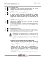
In order to reduce the risk of electric shock and to be sure that the equipment is correctly
installed and ready to operate, special safety symbols are used in this manual to highlight
potential safety risks or useful information. The symbols are the following:
WARNING: Paragraphs marked by this symbol contain actions and instructions
which must be understood and followed carefully to avoid potential harm to
people.
NOTE: Paragraphs marked by this symbol contain actions and instructions
which must be understood and followed carefully to avoid damage and
malfunctions to equipment.
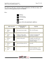
The equipment has various labels; those with a yellow background regard the safety
devices provided.
Make sure to have read and thoroughly understood the labels before installing the
equipment.
The symbols used are as follows:
System earth conductor (grid protection earth, PE)
Alternating Current (AC) Value
Direct Current (DC) Value
Phase
Grounding (ground)
Caution, hot surface
Danger, risk of electric shock. Time to discharge stored energy: 5
minutes.
Installation and operating manual
(PVI-3.8/4.6-I-OUTD-xx Rev.: 1.3)
Page 4 of 94
USEFUL INFORMATION AND SAFETY REGULATIONS
FOREWORD
The installation of AURORA inverters must be performed in compliance with
national and local regulations.
The AURORA inverter has no spare parts.
For all kinds of maintenance or repair, please contact the authorized repair centre
closest to you. Please contact the retailer in order to find out the location of the
closest service point.
It is strongly recommended to read all the instructions contained in this manual,
and to observe the symbols displayed in the individual paragraphs before
installing or using the equipment.
Connection to the distribution grid must only occur after having received approval
from the Authority or Body in charge of the distribution of electric energy, as is
required by the current national regulations, and must be carried out only and
exclusively by qualified personnel.
The entire solar panel must be covered with an opaque material before connecting
it to the appliance, as high voltages can occur in the connecting cables generating
conditions of serious hazard.
Installation and operating manual
(PVI-3.8/4.6-I-OUTD-xx Rev.: 1.3)
Page 5 of 94
GENERAL
When the inverter is operating, there can be parts that are live, or non-isolated, and in
some cases also moving or rotating, and, in addition, some surfaces may become hot.
Unauthorized removal of required protections, improper use, faulty installation or
incorrect operation may cause serious damage to persons and things.
All operations concerning transport, installation, commissioning, and maintenance
must be carried out by qualified and trained personnel only (all national standards
for the prevention of accidents must be respected!!!).
According to this basic safety rules, qualified and trained individuals must be experts
in the mounting, assembly, commissioning, and operation of the product, and must and
have the necessary skills, qualifications and requisites to carry out their tasks.
ASSEMBLY
The devices must be assembled and cooled down in accordance with the specifications
outlined in the relevant documentation.
In particular, during transportation and handling, the components must not be bent,
and the isolation distances must not be changed. There must be no contact between
electronic components and connection terminals.
Electrical components must not be mechanically damaged or destroyed (potential risk
for health).
ELECTRICAL CONNECTION
When working with the live inverter, national regulations regarding accident
prevention must be respected.
Electrical installation must be carried out in accordance with the relative regulations
(e.g. conductor sections, fuses, PE connection).
Installation and operating manual
(PVI-3.8/4.6-I-OUTD-xx Rev.: 1.3)
Page 6 of 94
OPERATION
The system in which the inverters are installed must be equipped with further control
and protection devices, in accordance with the relative applicable safety standards, e.g.
compliance with technical equipment, accident-prevention regulations, etc. Calibration
variations are possible through the use of the operational software. After having
disconnected the inverter from the mains grid, the live parts and the electrical
connections must not be touched for a while, as capacitors may still be charged. For
this reason, all the related signs and marks present on the devices must observed.
During operation, all covers and doors must be closed.
MAINTENANCE AND ASSISTANCE
The manufacturer’s documentation must be observed.
KEEP ALL DOCUMENTATION IN A SAFE PLACE!
Installation and operating manual
(PVI-3.8/4.6-I-OUTD-xx Rev.: 1.3)
Page 7 of 94
PVI-3.8-I-OUTD
PVI-3.8-I-OUTD-S
PVI-4.6-I-OUTD
PVI-4.6-I-OUTD-S
This documentation is only valid for the aforementioned inverter versions
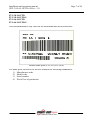
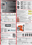
Product name plate (PVI-4.6-I-OUTD-S)
The name plate affixed to the inverter contains the following information:
informati
1) Manufacturer code
2) Model code
3) Serial number
4) Week/Year of production
Installation and operating manual
(PVI-3.8/4.6-I-OUTD-xx Rev.: 1.3)
Page 8 of 94
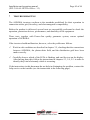
CONTENTS:
1
INTRODUCTION ............................................................................................ 11
1.1
2
PHOTOVOLTAIC ENERGY ................................................................... 11
DESCRIPTION OF THE SYSTEM ............................................................... 12
2.1
FUNDAMENTAL ELEMENTS OF A PHOTOVOLTAIC SYSTEM: “STRINGS” AND
“ARRAYS” ............................................................................................................. 14
2.2
DATA TRANSMISSION AND MONITORING .................................................... 16
2.3
TECHNICAL DESCRIPTION OF THE AURORA INVERTERS ........................... 16
2.4
PROTECTIONS ............................................................................................ 17
2.4.1 Anti-Islanding ........................................................................................... 17
2.4.2 Ground fault/RCD protection ................................................................... 18
2.4.3 Additional protective devices .................................................................... 18
3
INSTALLATION ............................................................................................. 19
3.1
PACKAGE INSPECTION ............................................................................... 19
3.2
INSPECTING THE PACKAGE CONTENTS ....................................................... 20
3.3
SELECTING THE LOCATION FOR INSTALLATION .......................................... 20
3.3.1 Wall mounting ........................................................................................... 23
3.4
PRELIMINARY OPERATIONS FOR ELECTRICAL CONNECTION ....................... 25
3.4.1 Procedure of CONNECTION / DISCONNECTION ................................. 26
3.4.2
Procedure for accessing the internal terminal blocks by removing the
front cover ..................................................................................................... 27
3.4.3
AC and DC wire selection ............................................................... 28
3.4.4 Installation of the AURORA inverter. ....................................................... 29
3.4.5 Possible configurations of input channels ................................................ 30
3.4.5.1
Connection with independent channels ...................................... 30
3.4.5.2
Parallel connection of channels .................................................. 31
3.4.6
Connection to the AC grid............................................................... 33
3.4.7 Connection of alarm cables and RS485 (optional) ................................... 34
3.4.8 Selection of grid standard ......................................................................... 34
3.4.9 Grounding of DC inputs............................................................................ 35
3.5
CR2032 LITHIUM BATTERY REPLACEMENT .............................................. 37
3.6
REPLACEMENT OF THE MEMORY ................................................................ 37
3.7
REPLACEMENT OF THE RS485 COMMUNICATION BOARD ........................... 38
Installation and operating manual
(PVI-3.8/4.6-I-OUTD-xx Rev.: 1.3)
4
COMMISSIONING AND SWITCHING OFF THE INVERTER ............... 39
4.1
4.2
4.3
5
Page 9 of 94
START-UP PROCEDURE ............................................................................... 39
START-UP USING THE SIDE BUTTON ............................................................ 41
SHUT-DOWN PROCEDURE ........................................................................... 41
USER INTERFACE, MONITORING, AND DATA TRANSMISSION ..... 42
5.1
USER INTERFACE MODE ............................................................................. 42
5.2
DATA TYPES AVAILABLE ............................................................................ 44
5.2.1 Real-time operational data........................................................................ 44
5.2.2 Data stored inside the inverter .................................................................. 45
5.3
LED INDICATORS ....................................................................................... 46
5.4
MESSAGES AND ERROR CODES ................................................................... 51
5.5
LCD DISPLAY ............................................................................................ 53
5.5.1 Connection of the system to the grid ......................................................... 53
5.5.2 Error messages.......................................................................................... 55
5.5.3 First phase - Electric parameter check ..................................................... 55
5.5.4 Main menu................................................................................................. 59
5.5.5 Statistics .................................................................................................... 60
5.5.5.1
Total ............................................................................................ 60
5.5.5.2
Partial .......................................................................................... 61
5.5.5.3
Today .......................................................................................... 61
5.5.5.4
Last 7 days .................................................................................. 62
5.5.5.5
Last month .................................................................................. 62
5.5.5.6
Last 30 days ................................................................................ 62
5.5.5.7
Last 365 days .............................................................................. 63
5.5.5.8
User period.................................................................................. 63
5.5.6 Settings ...................................................................................................... 64
5.5.6.1
Address ....................................................................................... 65
5.5.6.2
Imp. Display................................................................................ 65
5.5.6.3
Service ........................................................................................ 66
5.5.6.4
New password ............................................................................. 66
5.5.6.5
Currency...................................................................................... 66
5.5.6.6
Date/Time ................................................................................... 67
5.5.6.7
Language ..................................................................................... 67
5.5.6.8
START-UP Voltage .................................................................... 67
5.5.6.9
Autotest Operation ...................................................................... 67
5.5.6.10
Alarm .......................................................................................... 70
5.5.6.11
Remote Control ........................................................................... 71
5.5.6.12
UV Prot.time ............................................................................... 72
5.5.6.13
MPPT .......................................................................................... 73
Installation and operating manual
(PVI-3.8/4.6-I-OUTD-xx Rev.: 1.3)
Page 10 of 94
5.5.6.14
Alarm Message ........................................................................... 73
5.5.7 Info ............................................................................................................ 75
5.6
AUTOTEST PROCEDURE BY USING AURORA COMMUNICATOR.. 76
6
DATA CHECK AND COMMUNICATION .................................................. 81
6.1
6.1.1
6.1.2
6.1.3
CONNECTION THROUGH RS-485 SERIAL PORT OR RJ45 CONNECTORS ....... 81
RS-485 serial port ..................................................................................... 81
RJ45 connectors ........................................................................................ 82
Daisy chain ............................................................................................... 83
7
TROUBLESHOOTING ................................................................................... 85
8
TECHNICAL SPECIFICATIONS ................................................................. 87
8.1
8.2
8.3
8.4
8.5
INPUT VALUES ........................................................................................... 87
OUTPUT VALUES ........................................................................................ 90
GRID PROTECTION CHARACTERISTICS ........................................................ 90
GENERAL CHARACTERISTICS ..................................................................... 91
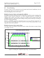
POWER DERATING ..................................................................................... 93
Installation and operating manual
(PVI-3.8/4.6-I-OUTD-xx Rev.: 1.3)
1
Page 11 of 94
INTRODUCTION
This document is a technical description of the AURORA photovoltaic inverter; the
aim of the document is to provide the installer and user with the necessary information
regarding the installation, operation and use of AURORA photovoltaic inverters.
1.1
PHOTOVOLTAIC ENERGY
In the energy transformation process, industrial companies (the greatest energy
consumers) have for many years now, been experimenting with ways of saving energy
and lowering pollutant emissions through the prudent and rational consumption of
known resources, and have been searching for new forms of clean and inexhaustible
energy.
Renewable energy sources provide a fundamental contribution to solving the problem.
In this context, the exploitation of solar energy to generate electrical energy
(photovoltaic) is becoming increasingly more important across the world.
Photovoltaic energy is a great advantage in terms of environmental protection as the
solar radiation that we receive from the sun is directly transferred into electrical energy
without involving any form of combustion and without producing waste products
which would pollute the environment.
Installation and operating manual
(PVI-3.8/4.6-I-OUTD-xx Rev.: 1.3)
2
Page 12 of 94
DESCRIPTION OF THE SYSTEM
AURORA is an inverter which is capable of feeding the power supply distribution grid
with energy obtained from photovoltaic panels.
The photovoltaic panels transform energy radiated by the sun into electrical energy in
the form of direct current, or DC (through a photovoltaic field, also known as a PV
generator); to feed the distribution grid, however, and in order to make energy
available for use, it is necessary to transform it into alternating current, or AC. This
conversion, known as DC-AC conversion, is carried out in an efficient way by the
AURORA inverters, without rotating elements, only using static electronic devices.
When used in parallel with the distribution grid, the alternating current output from the
inverter flows directly into the domestic circuit, which is in turn connected to the
public distribution grid.
The solar power system supplies energy to all that which is connected to it: from
lighting to all the different domestic appliances, etc.
In the event that the energy supplied from the photovoltaic system is lower than
required, the quantity of energy necessary to guarantee the normal operation of
connected appliances will be taken from the public distribution grid. If the opposite
occurs, that is excess energy is produced, it is sent directly into the public grid, thus
becoming available to other users.
In accordance with local and National regulations, the Energy product can be sold to
the distribution grid, or credited against future consumption, thus producing energy
savings.
Available versions
PVI-3.8-I-OUTD
PVI-3.8-I-OUTD-S
PVI-4.6-I-OUTD
PVI-4.6-I-OUTD-S
Page 13 of 94
Installation and operating manual
(PVI-3.8/4.6-I-OUTD-xx Rev.: 1.3)
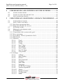
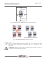
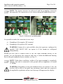
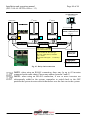
The models whose code ends in -S are supplied with an integrated DC switch 600 V,
25A as shown in Fig. 1.
+IN2
-IN2
+IN1
-IN1
600Vdc/25A
600Vdc/25A
600Vdc/25A
ON
600Vdc/25A
OFF
Switch Knob
GRID
TERMINAL BLOCKS
1
2
3
MAIN
GROUND
positive
grounding
negative
grounding
PTC-
PTC+
GND MODE
PTC-
PTC+
GND MODE
INPUT
TERMINAL BLOCK
+PV_IN2
-PV_IN2
+PV_IN1
-PV_IN1
FUSE-
FUSE+
GND MODE
PTC
+5V
GFCI & COUNTRY SEL.
COUNTRY SEL.
INPUT/OUTPUT
BOARD
EMI FILTER CH2
EMI FILTER CH1
AUX
INTERNAL SUPPLY
AC EMI FILTER
AURORA
INVERTER
BOOST CH2
INVERTER
BOOST CH1
DISPLAY / KEY
BOARD
LOGIC CONTROL BOARD
BOOST CH2
BOARD
BOOST CH1 +
INVERTER
BOARD
BRIDGE
RECTIFIER
BRIDGE
RECTIFIER
CAPS
BOARD
The models whose code does not end in -S are supplied without the 600V integrated
switch.
Fig. 1 - Block diagram of inverter without integrated DC switch
Installation and operating manual
(PVI-3.8/4.6-I-OUTD-xx Rev.: 1.3)
2.1
Page 14 of 94
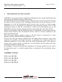
Fundamental elements of a photovoltaic system: “STRINGS” and
“ARRAYS”
In order to significantly reduce the costs of installing the photovoltaic system, costs
linked especially to the wiring problem of the inverter DC side, and to the subsequent
distribution on the AC side, the STRING technology was developed.
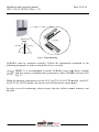
A photovoltaic panel is composed of many photovoltaic cells which are fixed onto the
same supporting base. A STRING is composed of a certain number of panels,
connected in series. An ARRAY is composed of one or more strings connected in
parallel.
Photovoltaic systems of a certain size can be composed of more than one array,
connected to one or more AURORA inverters.
By maximizing the number of panels inserted into each string, it is possible to reduce
the cost and complexity of the plant connection system.
PV Cell
+
PV Panel
PV String
+
+
_
_
_
Fig. 2 - Array Composition
Fig. 2 Array composition
PV Array
Installation and operating manual
(PVI-3.8/4.6-I-OUTD-xx Rev.: 1.3)
Page 15 of 94
WARNING: To prevent damage to equipment, the string voltage must
never exceed 520 Vdc. Due to the negative thermal coefficient of the open
circuit voltage of the photovoltaic module, maximum voltage is obtained in
conditions of minimum ambient temperature. It is advised to check the
configuration of the photovoltaic generator by means of the Aurora
Designer dimensioning software.
NOTE: A minimum Vstart input voltage of 200 Vdc (voltage can be set
from the control panel within the range of 120 Vdc to 350 Vdc) is required
in order to start the Aurora inverter grid connection sequence. Once
connected, the inverter will transfer the maximum available power to the
grid, for any Vdc input voltage value within the range between 70% of the
value set for Vstart, and 470V. The power transferred for each array is also
limited by the maximum manageable current (see paragraph below) (Error!
Reference source not found. and Error! Reference source not found.
show the limits for which maximum power is transferred).
The current of each array must also fall within the limits of the inverter. For the
AURORA inverters, the maximum current coming from each input can be 14Adc for
PVI-4.6-I-OUTD models, or 12.5 A for PVI-3.8-I-OUTD models.
In the event that the photovoltaic system exceeds the capacity of a single inverter,
other AURORA inverters can be added to the system. Each of these inverters will be
connected to an adequate section of the photovoltaic field on the DC side, and will be
connected to the distribution grid on the AC side.
Every AURORA inverter will work independently from the others, and, from its
section of photovoltaic panel, will supply the grid with the maximum available power.
Decisions regarding the structuring of a photovoltaic system depend on a certain
number of factors and considerations, including the type of panels, the availability of
space, the future location of the plant, long-term energy production targets, etc.
On the Power-One website (www.power-one.com) a configuration program is
available to help you dimensioning your photovoltaic system (Aurora Designer).
Installation and operating manual
(PVI-3.8/4.6-I-OUTD-xx Rev.: 1.3)
Page 16 of 94
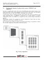
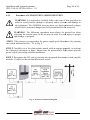
AC disconnect
switch
DC disconnect
switch
Fig. 3 - Simplified diagram of a photovoltaic system
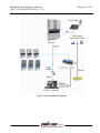
2.2
Data transmission and monitoring
If more than one inverter is used, they may be monitored, even remotely, by using an
advanced communication system which is based on the RS-485 serial interface. The
Aurora Easy-Control system is also available as an additional form of monitoring, and
allows for the remote monitoring of the system via the Internet or digital GPRS
modem. Furthermore, a system of radio monitoring is also available as an option (PVIDesktop + PVI-Radio module) to obtain a remote data display terminal, connected
wirelessly.
2.3
Technical description of the AURORA inverters
Fig. 1 shows the block diagram of an AURORA inverter. The main blocks are the
input DC-DC converters (known as “boosters”) and the output inverter. Both the DCDC converters and the output inverter work at a high switching frequency to enable a
compact design and a relatively low weight.
This version of inverter has a high frequency transformer, i.e. a transformer with
galvanic isolation between input and output. The high frequency transformer allow
galvanic isolation between the primary (DC side) and the secondary (AC side),
maintaining very high performance in terms of energy yield and export. The
AURORA inverters are equipped with all of the protections necessary for a safe
operation, in compliance with the applicable regulations as described in the paragraph
on protective devices.
Installation and operating manual
(PVI-3.8/4.6-I-OUTD-xx Rev.: 1.3)
Page 17 of 94
The block diagram shows the PVI-3.8/4.6-I-OUTD model with two independent
converters on DC-DC input. Each of these converters is dedicated to a separate array
with an independent Maximum Power Point Tracking (MPPT) control. This means
that the two arrays can be installed in different positions, facing in different directions.
Each array is controlled by an MPPT control circuit.
Due to the size and high efficiency of the AURORA inverters and the thermal
dissipation system, operation at maximum power in a wide range of ambient
temperatures is guaranteed.
The inverter is controlled by two independent DSPs (Digital Signal Processors) and by
a central microprocessor.
Connection to the power supply grid is thus controlled by two independent controllers,
in full compliance with the current regulations for electrical power supply and its
safety.
The AURORA inverter operating system communicates with related components in
order to carry out data analysis.
All of this ensures the optimal operation of the entire system and a high yield in all
isolation and load conditions, always fully respecting the relevant directives, laws and
regulations.
2.4
Protections
2.4.1
Anti-Islanding
In the event of a failure in the local distribution grid due to the power supply provider,
or if the machine is shut down for maintenance operations, the inverter must be
physically disconnected in a safe manner, in order to guarantee the protection of those
working on the grid, all in full compliance with the applicable national standards and
laws. In order to avoid any islanding operations, the inverter is equipped with an
automatic disconnection system, a protection known as “Anti-Islanding”.
The PVI-3.8/4.6-I-OUTD model is equipped with an advanced anti-islanding
protection system, certified according to the following directives:
Guide for connection to the ENEL low tension distribution grid
VDE V 0126-1-1
Royal Decree RD1663/2000 of Spain
UK G83/1
Installation and operating manual
(PVI-3.8/4.6-I-OUTD-xx Rev.: 1.3)
2.4.2
Page 18 of 94
Ground fault/RCD protection
WARNING: In some cases, national and local regulations make it obligatory
to connect one of the DC input terminals to the system ground. Carefully
refer the national standard in order to ground the inverter input correctly.
A specific connector allows connecting one and only one of the two DC input
terminals (positive or negative) to the ground. A sophisticated ground protection
circuit constantly monitors the ground connection, deactivates the inverter in the event
that a ground fault is detected, and indicates the ground fault condition through a red
LED located on the front panel. The AURORA inverter is equipped with terminals for
the system ground conductors.
For further information about the grounding of terminals and protections, refer to
section 3.4.9
NOTE: For further details about disconnecting the AURORA inverters or
about the causes of malfunction, refer to paragraphs 0
Protections against ground faults comply with the following directives:
Guide for connection to the ENEL low tension distribution grid
VDE V 0126-1-1
Royal Decree RD1663/2000 of Spain
UK G83/1
2.4.3
Additional protective devices
The AURORA inverters are equipped with additional protections in order to ensure its
safe operation under any circumstances. These protections include:
continual monitoring of the grid voltage to guarantee that the voltage and
frequency values remain within the operational limits;
internal temperature control in order to limit power automatically, should it be
necessary to ensure that the unit does not overheat (heat sink temperature ≤70°C
[158°F]).
The numerous control devices create a redundant structure, ensuring the
absolute safety of its operation.
Installation and operating manual
(PVI-3.8/4.6-I-OUTD-xx Rev.: 1.3)
3
Page 19 of 94
INSTALLATION
WARNING: the electrical installation of the AURORA inverters must be
performed in compliance with the applicable local and national standards and
laws.
WARNING: connecting the AURORA inverters to the power supply
distribution grid may only occur after having received authorization by the
utility operating that grid.
3.1
Package inspection
NOTE: The distributor delivered your AURORA inverter to the carrier
safely packaged, and in perfect condition. By accepting the package, the
carrier assumes responsibility for its delivery. Despite careful handling by the
carrier, both the packaging and its contents may have been damaged during
transport.
The client is invited to perform the following checks:
To examine the shipping container in order to check for visible damage, holes,
cracking, or any other sign of possible damage to its contents;
To describe any damage or missing parts on the delivery documents, and to
obtain the carrier's full name and signature;
To open the shipping container and examine its contents to check for any internal
damage. When unpacking, make sure not to discard any equipment, components,
or manuals. In the event that some form of damage is detected, contact the
delivery carrier to determine the appropriate course of action. As the carrier may
request an inspection, it is important to keep all shipping material for the
inspector!
Should the inspection detect damage to the product, please contact your local
supplier or authorized distributor. They will determine whether the equipment
must be returned for repair, and will provide the relevant instructions for doing
so;
It is the client's responsibility to file a complaint with the carrier. Failure to do so
may result in the loss of all warranty service rights for any reported damage;
Keep original shipping package in case the device has to be returned for repair.
Installation and operating manual
(PVI-3.8/4.6-I-OUTD-xx Rev.: 1.3)
3.2
Page 20 of 94
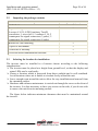
Inspecting the package contents
Description
AURORA Inverter
Quantity (No.)
1
Bag containing:
4 screws 6.3x70, 4 SX10 anchors, Torx20
screwdriver, 1 screw 6x10, 5 washers d. 18, 2
counterparts for signal connectors (3 poles), 2
counterparts for signal connectors (8 poles)
1
Bracket for wall mounting
1
Copies of this manual
1
Certificate of warranty
1
CD-ROM with communication software
1
3.3
Selecting the location for installation
The inverter must be installed in a location chosen according to the following
considerations:
The inverter must be placed at a height from ground level, so that the display and
status LEDs can be read easily.
Choose a location which is protected from direct sunlight and is well-ventilated.
Avoid locations where air is unable to circulate freely around the unit.
Leave enough room around the unit to allow for easy installation and removal from
the mounting surface.
Hardware and software maintenance is carried out through the cover on the front of
the inverter. It is thus necessary to have easy access to this side, if you do not wish
to remove the unit from its mounting surface.
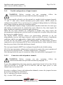
The figure below indicates minimum clearances that must be maintained around
the inverter:
Installation and operating manual
(PVI-3.8/4.6-I-OUTD-xx Rev.: 1.3)
Page 21 of 94
150mm (6”)
50mm
(2”)
150mm
.(6”)
200mm (8”)
Fig. 4 - Installation location - Minimum clearances around the inverter
RECOMMENDED POSITIONING
Fig. 5 - Recommended installation of Aurora inverters
NOTE: Although titled mounting is possible (see Fig. 6), please note that
this may reduce performance (Derating), due to a reduction in heat
dissipation.
WARNING: During operation, the unit surface may become very hot. To
avoid burns, DO NOT touch the surface.
Installation and operating manual
(PVI-3.8/4.6-I-OUTD-xx Rev.: 1.3)
Page 22 of 94
NO Derating
Derating
-5°
Derating
0°
5°
Derating
Fig. 6 - Titled mounting
AURORA must be mounted vertically. Follow the information contained in the
following paragraphs in order to mount the device correctly.
NOTE. It is recommended to install AURORA away from direct sunlight
and heat sources, including heat generated by other AURORA inverters (see
Fig. 5)
When the ambient temperature exceeds 50°C for PVI-4.6-I-OUTD
OUTD models,
models and 60°C
for PVI-3.8-I-OUTD models, the inverter will self-derate
derate the output power.
In order to avoid overheating, always ensure that the airflow around Aurora is not
blocked.
Installation and operating manual
(PVI-3.8/4.6-I-OUTD-xx Rev.: 1.3)
Page 23 of 94
3.3.1
Wall mounting
Included in the shipping package is a kit containing 4 steel screws 6.3x70 (with 4 M6
washers) and 4 SX10 anchors,
s, necessary for attaching the metal bracket to a concrete
wall. Screws and anchorss can be inserted into the 3 holes on the metal bracket (Part.
(Pa
B), and then into the hole on the bottom of the inverter.
WARNING: The bracket must be attached to the wall vertically, the side
with the hook (Part. C) must be facing upwards, while the side with the PEM
M6 (Part. G) must be facing downwards.
NOTE: If the device is to be mounted onto a concrete wall, holes must be
created of diameter 10mm and depth 75mm.
NOTE: When the device is installed on walls of materials other than
concrete, suitable screws and anchors should be used. Power-One
Power
recommends always using stainless steel screws.
Attach the inverter to the hook (Part. C) present on
n the upper part of the bracket by
using the metal fin, fixed onto the upper part of the rear of the inverter. This metal fin
has a point (Part. D) in correspondence to the fixing hook of the wall-mounting
wall
bracket (Part. C).
Once the upper part of the inverter has been attached, fix the lower part to the PEM
M6 present on the bracket, by using the special slot on the lower flange of the inverter
(Part. H).
Installation and operating manual
(PVI-3.8/4.6-I-OUTD-xx Rev.: 1.3)
Fig. 7 – Wall mounting
Page 24 of 94
Installation and operating manual
(PVI-3.8/4.6-I-OUTD-xx Rev.: 1.3)
3.4
Page 25 of 94
Preliminary operations for electrical connection
WARNING: The electrical connection must only be made after the inverter
has been firmly fixed to the wall.
WARNING: The connection from the inverter to the power supply
distribution grid must be performed exclusively by qualified personnel, and
only after authorisation has been received from the power supply provider
managing the distribution grid.
WARNING: For details regarding each individual operation, it is necessary
to read and follow the instructions in this chapter (and sub-chapters), and all
safety warnings. Read the instructions carefully and follow them step-bystep. Any operation which does not conform to what follows may cause
hazardous conditions for the operator/installer, and can cause damage to the
equipment.
WARNING: When designing the system, always respect the voltage and
current nominal ratings, as indicated in chapter 8 (Technical Specifications).
The following, in particular, must be kept in mind when designing the
photovoltaic field:
Maximum DC input voltage to each of the two MPPT circuits: 520
Vdc.
Maximum DC input current to each of the two MPPT circuits: 14Adc
(PVI-4.6-I-OUTD), and 12.5Adc (PVI-3.8-I-OUTD).
WARNING: Check the national regulations and local standards, so that
electrical installation complies with them.
In accordance with the assembly diagram, a main isolator, comprised of an automatic
magnetothermic switch should be inserted between the inverter and the distribution
grid, on the AC output side. The characteristics of the main isolator or automatic
switch are 20A 230V for PVI-3.8-I-OUTD, and 25A 230V for PVI-4.6-I-OUTD.
Installation and operating manual
(PVI-3.8/4.6-I-OUTD-xx Rev.: 1.3)
3.4.1
Page 26 of 94
Procedure of CONNECTION / DISCONNECTION
WARNING: It is advised to carefully follow the steps of this procedure in
order to avoid possible damage to property and/or persons and damage to
the equipment. The AURORA inverters have very high operational voltages
which can be extremely dangerous if all precautions are not observed.
WARNING: The following
wing operations must always be carried out when
accessing the interior parts of the inverter in order to avoid injury to people
and damage to property.
STEP 1 If the inverter is connected to the power supply grid, disconnect it by opening
the switch indicated as Part. “D” in Fig. 8
STEP 2 Carefully cover the photovoltaic panels with an opaque material, or perform
the following operations at night. Ensure that the photovoltaic
taic field cannot provide
power before proceeding with the installation.
STEP 3 Disconnect the DC part by opening the integrated disconnect switch (models
with the -S suffix) or the external disconnect switch.
Fig. 8 - Electrical connection diagram
Installation and operating manual
(PVI-3.8/4.6-I-OUTD-xx Rev.: 1.3)
Page 27 of 94
WARNING: When selecting cables, several factors have to be considered:
nominal voltage, isolation rating, maximum operating temperatures, current
rating, and flammability rating, in accordance with the national regulations of
the country of installation. Procedure for accessing the internal terminal
blocks by removing the front cover
3.4.2
Procedure for accessing the internal terminal blocks by removing the
front cover
WARNING: Before removing the front cover, ensure that the AURORA
inverter has been disconnected from both the AC and DC sides for at least 5
minutes, in order to allow for the internal capacitors to discharge, and thus to
avoid the risk of electrocution.
To remove the front cover, loosen the 4 screws shown in Fig. 9 using the Torx
screwdriver provided.
3
1
4
2
Fig. 9 - Front cover of the inverter
Once the cover has been reassembled, ensure to tighten the screws at a torque of at
least 1.5Nm (13.2 in-lbs) for ensuring a watertight seal.
Installation and operating manual
(PVI-3.8/4.6-I-OUTD-xx Rev.: 1.3)
3.4.3
Page 28 of 94
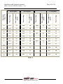
AC and DC wire selection
The following tables will help the installer to select AC and DC wires
DC input wiring
Ground
AC output wiring
Main ground
PVI-3.8-I-OUTD
AWG
167°F
(75°C)
PVI-3.8-I-OUTD
8-6
PVI-3.8-I-OUTD
4
PVI-3.8-I-OUTD
8-6
PVI-3.8-I-OUTD
6
AWG
194°F
(90°C)
10-6
4
10-6
6
DC input wiring
Ground
AC output wiring
Main ground
PVI-4.6-I-OUTD
AWG
167°F
(75°C)
PVI-4.6-I-OUTD
8-6
PVI-4.6-I-OUTD
4
PVI-4.6-I-OUTD
8-6
PVI-4.6-I-OUTD
6
AWG
194°F
(90°C)
10-6
4
8-6
6
Installation and operating manual
(PVI-3.8/4.6-I-OUTD-xx Rev.: 1.3)
3.4.4
Page 29 of 94
Installation of the AURORA inverter.
WARNING: The maximum DC input current to each of the two MPPT
circuits should not exceed 14Adc (PVI-4.6-I-OUTD), and 12.5Adc (PVI-3.8I-OUTD), under any conditions.
WARNING: Follow the procedure step-by-step in order to avoid damage to
things and injury to people.
Step 1: Disconnect the inverter from the AC grid by turning off the AC switch, "part
D" in Fig. 8. Also turn off the DC part by using the DC switch (integrated in -S models
or external).
Step 2: Remove the inverter front cover as described in paragraph 0. Connect the DC
cables to the inverter, carefully checking the correct polarity. For possible connection
types, refer to 3.4.5.
Step 3: Connect the AC cables to the terminal block, following the instructions laid
out in paragraph 3.4.6.
Step 4 (optional): Connect the signal cables to the specific terminal block. Replace
one of the capped holes present on the bottom of the inverter with a cable gland
(supplied) and use it to pass through the wires..
Step 5: Remove the cover from the photovoltaic panels
WARNING: Verify the polarity and the no-load voltage on the inverter
terminal block to ensure that the connection has been made correctly.
If the parameters fall within the range defined by the inverter’s technical
specifications, reclose the inverter by replacing the cover and tightening the screws as
described in paragraph 0, then and proceed to section 4.
Installation and operating manual
(PVI-3.8/4.6-I-OUTD-xx Rev.: 1.3)
3.4.5
Page 30 of 94
Possible configurations of input channels
WARNING: Before carrying out any operation, follow
connection/disconnection procedure detailed in paragraph 3.4.1.
the
The inverter models referred to in this manual are supplied with two input channels,
“1” and “2” (thus with a double maximum power point tracker, MPPT) which are
configured in parallel. They can however be configured independently by following
some simple operations during the installation phase.
To each individual channel, strings of photovoltaic modules which have the same type
and number of panels must be connected in series. Moreover, they must require the
same installation conditions (orientation and inclination).
When the two input channels are configured in parallel, they must respect the
aforementioned requirements with the benefit of being able to exploit full power from
the inverter in a single channel.
The double MPPT structure allows two photovoltaic generators to be run
independently (one for each input channel), which can differ in terms of installation
conditions, and the type and number of photovoltaic modules connected in series.
In order for the two MPPT to be used independently, the photovoltaic generator
connected to each of the inputs MUST have current and power values which are lower
than the power limit of the individual input channel.
The two input channels (MPPT) are configured in parallel as the default setting.
All of the input parameters which must be respected to ensure the correct operation of
the inverter are reported in the “Technical characteristics” paragraph.
After having chosen the type of connection, follow the instructions in paragraph 3.4.4
3.4.5.1
Connection with independent channels
WARNING: Before carrying out any operation, follow
connection/disconnection procedure detailed in paragraph 3.4.1.
the
To use this configuration, the input current to each channel must be less than 14Adc
(PVI-4.6-I-OUTD) or 12.5Adc (PVI-3.8-I-OUTD) and the input power to each
channel must be less than 3kW.
In order to configure Aurora with independent channels, remove the jumpers between
the positive and negative terminals in
Fig. 10, and move the selector switch in
Fig. 11 to the “IND” position.
Installation and operating manual
(PVI-3.8/4.6-I-OUTD-xx Rev.: 1.3)
3.4.5.2
Page 31 of 94
Parallel connection of channels
WARNING: Before carrying out any operation, follow
connection/disconnection procedure detailed in paragraph 3.4.1.
the
Use this configuration when the input current to one of the channels is greater than
14Adc (PVI-4.6-I-OUTD) or 12.5Adc (PVI-3.8-I-OUTD), or when the input power to
one of the channels is greater than 3kW.
Parallel configuration is the factory setting therefore, it is not necessary to change the
connections.
Fig. 10 – Parallel connection of channels
Check that the jumpers are inserted and that the selector switch in
Fig. 11 is in the "PAR" position.
Installation and operating manual
(PVI-3.8/4.6-I-OUTD-xx Rev.: 1.3)
Fig. 11 – Parallel/independent configuration switch
Page 32 of 94
Installation and operating manual
(PVI-3.8/4.6-I-OUTD-xx Rev.: 1.3)
3.4.6
Page 33 of 94
Connection to the AC grid
WARNING: Before carrying out any operation, follow
connection/disconnection procedure detailed in paragraph 3.4.1.
the
Step 1: Remove the front cover of the inverter as shown in section 0.
Step 2: Connect the AC cables from the external disconnector to the internal inverter
terminal box indicated by the serigraphy “GRID”.
Step 3: Install the cable gland (supplied) onto the dedicated hole located on the bottom
of the inverter and use it to pass through the AC cables.
Step 4: Connect the 3 AC conductors to the inverter terminal box, following the
serigraphy.
-
Terminal
for protective earth PE (the screw located next to the
symbol can also be used for connecting to the earth conductor)
terminal 1 for Neutral N,
terminal 2 Line L,
A
Fig. 12 - Terminal Block for connection to AC conductors
Installation and operating manual
(PVI-3.8/4.6-I-OUTD-xx Rev.: 1.3)
3.4.7
Page 34 of 94
Connection of alarm cables and RS485 (optional)
WARNING: Before carrying out any operation, follow
connection/disconnection procedure detailed in paragraph 3.4.1.
3.4.1
the
Step 1: Remove the front cover of the inverter as shown in section 0..
Step 2: Replace one of the holes present on the bottom of the inverter with a cable
gland (supplied) and use it to pass though the alarm relay or signal cables.
Step 3: Connect the wires by following the serigraphy of the signal connector.
3.4.8
Selection of grid standard
WARNING: Before carrying out any operation, follow
connection/disconnection procedure detailed in paragraph 3.4.1.
3.4.1
the
The inverter is provided with two rotary selectors (Error!
Error! Reference source not
found.)) which allow installers to choose which grid standard they wish to apply. The
unit is delivered with the selector switches set in the ‘0’’0’ position (default setting).
To allow the Aurora photovoltaic inverter to operatee regularly, installers must select
the grid standard in accordance with the national regulations,
es, remove the front cover as shown in paragraph 0.
To access the selector switches,
NOTE: The ‘0’’0’ default
lt position does not allow connection to the power
supply grid.
Select the standard based on the following table:
Left selector
Right selector
Grid standard
switch
switch
0
0
Standard de-selected
0
1
VDE 0126
0
2
UL 1741 @208V
0
3
UL 1741 @240V
0
4
UL 1741 @277V
0
5
ENEL
8
8
Reserved
F
F
Reserved
Language
English
German
English
English
English
Italian
Installation and operating manual
(PVI-3.8/4.6-I-OUTD-xx Rev.: 1.3)
(*)
Page 35 of 94
The table above is the basic table; further additions can be added when new
standards become available
Once the standard has been chosen, a meter will begin to scan the connection to the
grid for 24 hours. Before 24 hours expire, the selected standard can still be changed.
Once the 24 hours have passed, the Power-One assistance center would have to send
an Authorization Key to unblock the inverter, and allow further changes. Remaining
time can be checked on the information menu
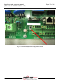
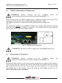
Fig. 13 - Selector switches for grid standard and grounding connector positioner
3.4.9
Grounding of DC inputs
WARNING: Before carrying out any operation, follow
connection/disconnection procedure detailed in paragraph 3.4.1.
the
These inverter models are equipped with a special connector for grounding one of the
input terminals.
By positioning of this connection, it is possible to choose which terminal to connect to
the ground. Error! Reference source not found. shows the cables and the connectors
to which they must be connected in order to make the grounding effective.
Installation and operating manual
(PVI-3.8/4.6-I-OUTD-xx Rev.: 1.3)
Page 36 of 94
NOTE: The Aurora inverters are delivered with the grounding connection
disconnected. The connection is to be chosen during the installation process.
Fig. 14 - Connectors for grounding inputs
It is possible to make the connection in two ways:
a) Grounding of the negative DC terminal.
b) Grounding of the positive DC terminal.
WARNING: Option b) is only available when the inputs are configured in
parallel. YOU MUST NOT use option b) if the inputs are configured
independently.
Should you not wish to connect either of the two input terminals directly to the
ground, you can disconnect the connector and store it within the dedicated housing
next to the grid standard selector switches, see Fig. 13.
NOTE: Under these conditions, neither of the input terminals is completely
floating, but each is connected to the ground with an impedance of around
1.5 Mohm.
WARNING: Depending on the grid standard chosen (see section 3.4.8), the
inverter will be able to recognize any grounding which does not respond to
the applicable regulations and an error message will appear on the display.
Installation and operating manual
(PVI-3.8/4.6-I-OUTD-xx Rev.: 1.3)
3.5
Page 37 of 94
CR2032 Lithium Battery Replacement
WARNING: Before carrying out any operation, follow
connection/disconnection procedure
dure detailed in paragraph 3.4.1.
the
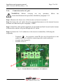
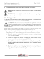
Inside Aurora, there is a CR2032 lithium battery. When the battery is at its end-of-life,
end
a message will be shown on the display indicating the battery state.
The battery can easily
asily be seen once the front panel has been removed (see
Fig. 15).
The component cannot be assembled vertically to its container, but it must be inserted
from the side (Side A), at an angle of around 30°. The component
nent will rotate inside the
battery port until it seats in the right position.
Fig. 15 – Lithium battery replacement
WARNING: The battery must be replaced by qualified personnel only.
3.6
Replacement of the memory
WARNING: Before
efore carrying out any operation, follow
connection/disconnection procedure detailed in paragraph 3.4.1.
the
All historical data relative to the system energy production are stored in this memory.
If the inverter
er must be replaced, the memory can simply be removed from the old unit,
and reinserted into the new one. By so doing, you can continue to save present and
future daily data on this memory, and avoid losing the data already stored in it. See
Error! Reference source not found.
Installation and operating manual
(PVI-3.8/4.6-I-OUTD-xx Rev.: 1.3)
Page 38 of 94
Fig. 16 - Inverter memory
WARNING: This component must be replaced by qualified personnel
only.
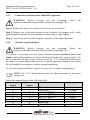
3.7
Replacement of the RS485 communication board
WARNING: Before carrying out any operation, follow
connection/disconnection procedure detailed in paragraph 3.4.1.
the
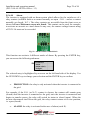
It is possible to replace the RS485 communication board.
Fig. 17 - RS485 Board
WARNING: This component must be replaced by qualified personnel only.
Installation and operating manual
(PVI-3.8/4.6-I-OUTD-xx Rev.: 1.3)
4
Page 39 of 94
COMMISSIONING AND SWITCHING OFF THE INVERTER
WARNING: do not place any items of any sort on top of AURORA during
operation.
WARNING: do not touch the heart sink when the inverter is operating as
some parts may be extremely hot.
4.1
Start-up procedure
To start the inverter and interact with the display using the keypad, a minimum voltage
of 130Vdc is necessary on at least one of the DC INPUTS.
WARNING: The Aurora inverters are designed to be supplied by sources of
limited current (solar panels). It is thus recommended not to use sources that
may supply sudden peaks of current capable of damaging the circuitry (for
example, batteries).
Should the DC source (panel) be unavailable, it is possible to force the start-up of the
display for brief periods by supplying it from the grid (see paragraph 4.2).
Depending on the DC input voltage present, the inverter will behaves as follows:
a)
When the inverter is switched off, it starts up as soon as an input voltage
value of 130V is reached.
b) The inverter displays the message "Awaiting Sun" until the input voltage
exceeds the set Vin start value (see paragraph 5.5.6.8).
c)
When the Vin start value is exceeded, the inverter displays the message “Vac
absent” if the grid is not connected, whereas if the grid is present the inverter
connects to it.
d) The inverter will stay connected to the grid if the input voltage is between
70% of the set Vin start value and 520 Vdc. If the input voltage is outside this
range, the inverter disconnects from the grid.
Installation and operating manual
(PVI-3.8/4.6-I-OUTD-xx Rev.: 1.3)
Page 40 of 94
The procedure for commissioning AURORA is as follows:
1) Set the inverter integrated DC disconnector (for the photovoltaic panels) to
the ON position
2) NOTE: The DC disconnector
or of the panels may or may not be
integrated into the inverter, depending on the chosen model.
2) Set the external AC disconnector (related the grid) to the ON position.
The two disconnectors can be closed in any order, without the need of giving
priority to one over the other.
3) Once the two disconnectors are closed, the inverter starts the grid parameter
control sequence. This operation will be indicated by the flashing of the green
LED (which is labeled POWER and located on the display).
This check
eck may take from a minimum of 30 seconds to a maximum of some
minutes, depending on the conditions of the grid itself.. During the process, a
sequence of three screens appears on the display:
•
Grid voltage value, and indication of status with respect to the
th values of the
technical specifications, if within or outside of the range foreseen.
foreseen
•
Grid frequency value, and indication of status with respect to the values of
the technical specifications, if within or outside of the range.
4) Once the connection processs has been completed, AURORA starts to operate,
signaling its correct functioning by emitting a warning sound and by keeping
the green LED continually on.
5) If the grid check does not give a positive result, the unit repeats the procedure
again, until all the grid voltage parameters are within the range. During this
phase, the green LED will be flashing.
Installation and operating manual
(PVI-3.8/4.6-I-OUTD-xx Rev.: 1.3)
4.2
Page 41 of 94
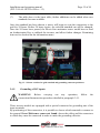
Start-up using the side button
If DC voltage is not present but the AC grid is properly connected and you wish to
start the inverter, press the side button shown in Error! Reference source not found.
for more than 2 seconds. A beep indicates that the system has acknowledged the input
given by pressing the button.
The inverter will remain switched on for 10 minutes, allowing for the monitoring of
any type of value on the display (statistics, settings, etc.). The inverter will not connect
itself to the grid until a valid and stable DC input voltage is present. When the inverter
is started up under these conditions (with no DC), its consumption is less than 20W.
Fig. 18 – Button for starting-up the inverter from the grid
4.3
Shut-down procedure
The inverter can be shut down in three different ways:
1) Disconnect DC and the AC grid by disconnecting their disconnectors (in any
order). The inverter will shut down after a few seconds, which are required in
order to discharge the internal capacities.
2) Disconnect DC by disconnecting the relative disconnector, and wait for the
set UV prot. Time (see paragraph 5.5.6.12).
3) Disconnect the grid by disconnecting its disconnector, with a DC input lower
than 80 Vdc.
Installation and operating manual
(PVI-3.8/4.6-I-OUTD-xx Rev.: 1.3)
5
5.1
Page 42 of 94
USER INTERFACE, MONITORING, AND DATA TRANSMISSION
User interface mode
Normally, the AURORA inverter operates automatically, and does not require any
particular controls. When solar radiation is sufficient to generate power to be input
into the grid (for example, at night), AURORA automatically disconnects itself,
entering into stand-by mode.
The operating cycle is automatically resumed when solar radiation becomes sufficient.
This will be indicated by the LEDs.
The AURORA inverter is capable of supplying operational information through the
following instruments:
Indicator lights (luminous LEDs)
Operational data shown on the LCD display
Data transmission on a dedicated serial RS-485 line. Data can be collected from a
PC or data logger, equipped with an RS-485 port. If an RS-485 line is employed,
it may be beneficial to use the RS485-USB converter, model number PVI-USBRS485_232. Furthermore, it is possible to use the PVI-AEC-EVO data logger.
WARNING: the RS-485 cable must ensure a protection of at least 600V.
Installation and operating manual
(PVI-3.8/4.6-I-OUTD-xx Rev.: 1.3)
Fig. 19 - Data Transmission Options
Page 43 of 94
Installation and operating manual
(PVI-3.8/4.6-I-OUTD-xx Rev.: 1.3)
5.2
Page 44 of 94
Data types available
AURORA supplies two types of data which can be read through the display and/or
through the appropriate interface software.
5.2.1
Real-time operational data
Real-time operational data can be transmitted on demand through the communication
lines, and will not be internally registered inside the inverter. For transmitting data to a
PC, the free AURORA Communicator software can be used. This software is included
in the installation CD (please check the website www.power-one.com for the latest
updated version).
The following data is available:
Grid voltage
Grid current
Grid frequency
Power transferred to the grid
Voltage of photovoltaic array 1
Current of photovoltaic array 1
Voltage of photovoltaic array 2
Current of photovoltaic array 2
Temperature of internal semiconductors
Serial number of Code
Week of production
Firmware revision code
Daily energy
System earth leakage current
Total energy
Partial energy
Mean grid voltage
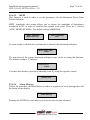
Isolation resistance
Leakage current to the ground
Date, time
Daily peak power
Absolute peak power
Input power
Installation and operating manual
(PVI-3.8/4.6-I-OUTD-xx Rev.: 1.3)
Page 45 of 94
5.2.2
Data stored inside the inverter
AURORA stores the following data internally:
Total meter of grid connection time
Total meter of energy transferred to the grid
Partial meter of energy (uses the same start time as the partial time meter)
Daily energy meter
Weekly energy meter
Monthly energy meter
Annual energy meter
Energy meter over last 7 days
Energy meter over last 30 days
Energy meter over last 365 days
Energy meter for a user-defined period
Daily energy buffer produced over the last 366 days
Buffer of last 100 fault signals with error code and time mark
All the meter data is shown on the LCD display and on the RS-485 interface; the daily
energy and error buffers can only be viewed through the RS-485 interface.
Installation and operating manual
(PVI-3.8/4.6-I-OUTD-xx Rev.: 1.3)
5.3
Page 46 of 94
LED indicators
At the side of the display, there are three LEDs. The first from the left (POWER)
indicates the proper functioning of the inverter; the central LED (FAULT) indicates
the presence of an anomaly; and the right-hand LED (GFI) indicates a ground fault.
1. The green LED “Power” indicates that AURORA is operating correctly.
When the unit is undergoing commissioning, and the grid is being checked, this
LED will be flashing. If a correct grid voltage is detected, the LED will stop
flashing, and will emit a steady light, as long as solar radiation is sufficient to start
up the unit. If not, the LED will continue to flash until solar radiation becomes
strong enough to start up the inverter. During this phase, the LCD display will
show the message "Awaiting sun..."
2. The yellow LED "FAULT” indicates that AURORA has detected a fault. The type
of problem will be shown on the display.
3. The red LED “GFI” (ground fault) indicates that AURORA is detecting a ground
fault in the DC side of the photovoltaic field. When a fault is detected, AURORA
will immediately disconnect itself from the grid, and the relative error message will
appear on the LCD display. AUORA will remain in this state until the operator
presses the ESC key in order to restart the grid connection process. If AURORA
does not re-connect itself to the grid, technical assistance must be called in order to
identify and remove the cause of the system fault.
1
2
3
ESC
UP
Fig. 20 - Location of buttons and LEDs
DOWN
ENTER
Installation and operating manual
(PVI-3.8/4.6-I-OUTD-xx Rev.: 1.3)
Page 47 of 94
The following table shows all the possible combinations of LED activation, with
reference to the operational state of AURORA.
Key:
LED on
LED flashing
LED off
Any of the aforementioned conditions
LED STATUS
OPERATIONAL
STATUS
NOTES
1
green:
yellow:
red:
AURORA selfdisconnection at night
Input voltage less than 90
Vdc for both inputs
2
green:
yellow:
red:
AURORA initialization,
loading settings and
waiting for grid check
It is in a transition status
needed for checking the
operating conditions
green:
yellow:
red:
AURORA is transferring
energy to the grid
The machine is operating
normally (search for the
maximum power point or
constant voltage)
green:
yellow:
red:
Anomaly detected in the
system isolation device
Leakage to the ground
detected
green:
yellow:
red:
Anomaly – fault!!!
The fault may an internal or
external anomaly, see the
report on the LCD display
3
4
5
Installation and operating manual
(PVI-3.8/4.6-I-OUTD-xx Rev.: 1.3)
6
7
Page 48 of 94
green:
yellow:
red:
Installation phase:
AURORA is
disconnected from the
grid.
During installation, it
indicates the address setting
phase for RS-485
communication
Green:
yellow:
red:
Disconnection from the
grid
Indicates that the grid is
missing
NOTE: In correspondence with each of the inverter states, signaled via the
constant or intermittent lighting up of the relevant LED, a message
identifying the operation which is being performed or the fault/defect
detected will also be displayed on AURORA LCD display (see the
following paragraphs).
Installation and operating manual
(PVI-3.8/4.6-I-OUTD-xx Rev.: 1.3)
Page 49 of 94
V
G
R
1) Night-time mode
AURORA is in its night-time shut-down phase; this happens
when the input power is too low to feed the inverter.
V
G
R
2) AURORA initialization and grid check
The machine is in its initialization phase. Input power is sufficient
to feed the inverter. AURORA is checking that the conditions
necessary for start-up have been satisfied (for example, input
voltage value, isolation resistance value, etc.), and starts the grid
check.
V
G
R
3) AURORA is feeding the grid
After having completed the series of autotests, the machine
connects itself to the grid.
As previously mentioned, AURORA will automatically perform a
search and analysis of the maximum power point (MPPT) of the
photovoltaic field.
V
G
R
4) Ground isolation fault
AURORA indicates that the isolation resistance value is too low.
The problem may be linked to an isolation fault in the connection
between the photovoltaic field inputs and the ground.
WARNING: it is extremely dangerous to attempt to correct the
fault yourself. The instructions below must be followed very
carefully. Please contact a specialist if you do not possess the
experience or qualifications necessary to work safely on the
system.
What to do after an isolation fault has been detected
When the red LED turns on, try to reset the fault indication by
using the multifunctional ESC button at the side of the LCD
display. If AURORA reconnects to the grid normally, the fault
was due to temporary circumstances (for example, infiltration of
humidity onto the panels due to condensation).It is
recommended to allow a specialized technician to inspect the
machine if the fault continues to occur. It is recommended to
allow a specialized technician to inspect the machine if the fault
continues to occur.
If AURORA does not reconnected to the grid, it is necessary to
Installation and operating manual
(PVI-3.8/4.6-I-OUTD-xx Rev.: 1.3)
Page 50 of 94
put AURORA into a safe condition by isolating it on both the
DC and AC sides and contacting an authorized centre in order to
have the fault repaired.
V
G
R
5) Anomaly-Fault indication
Each time that AURORA's check system detects an anomaly or
fault in the operation of the monitored system, the yellow LED
lights up continually and a message indicating the type of
problem detected will appear on the LCD display.
V
G
R
6) Internal ventilation system anomaly
Indicates that the ventilation system is not woking correctly. This
should not cause problems as the fan is only activated when high
temperatures are combined with high output power.
V
G
R
7) Grid disconnection
When the system is functioning normally and a grid failure event
occurs, the yellow LED will immediately light up with a steady
light, and the green LED will flash.
Installation and operating manual
(PVI-3.8/4.6-I-OUTD-xx Rev.: 1.3)
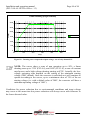
5.4
Page 51 of 94
Messages and error codes
The system status will be identified by message or error signals, shown on the LCD
display.
The tables below summarized the two types of signals which may be displayed.
The MESSAGES indicate the current status of AURORA, they are not caused by
faults and do not involve any action; the messages will disappear once normal
conditions are re-established (See the W lines in the following table).
ALARMS indicate a possible fault in the equipment or connected parts. The signal
will disappear once causes are removed, except in the case of ground isolation
problems, for which qualified personnel will have to be called in order to have the
system restored to normal operation. The appearance of an error signal generally
involves some form of action by the installer of by the Power-One Service. The
AURORA photovoltaic inverters will show on display much helpful information as
possible to those performing the necessary maintenance on the equipment or system.
See the E line in the following tables.
Message
Sun Low
Error
warning
W001
Error
type
//
Input OC
Input UV
Input OV
Int.Error
//
W002
//
//
E001
//
E002
E003
Bulk OV
Int.Error
//
//
E004
E005
Out OC
Int. Error
Sun Low
Int.Error
//
//
W011
//
E006
E007
//
E009
Message
Grid Fail
Error
warning
W003
Error
type
//
Int.Error
Int.Error
DC/DC Fail
//
//
//
E010
E011
E012
Description
Input Voltage under threshold
Input voltage under threshold (in OFF status)
Input Overcurrent
Input Undervoltage
Input Overvoltage
No parameters
No parameters
Bulk Overvoltage
Internal Communication Error
Communication error in internal bus
Output Overcurrent
IGBT Sat
Bulk Undervoltage
Internal Error
Internal error
Description
Grid Fail
Grid out of range
Bulk Low
Ramp Fail
Internal error
Installation and operating manual
(PVI-3.8/4.6-I-OUTD-xx Rev.: 1.3)
Wrong Mode
//
E013
Over Temp.
//
E014
Cap. Fault
//
E015
Inv. Fail
Int.Error
Ground F.
//
//
//
E016
E017
E018
Int.Error
//
E019
Int.Error
//
E020
Int.Error
//
E021
Int.Error
//
E022
Int.Error
Int.Error
Int.Error
//
//
//
E023
E024
E025
Int.Error
Int.Error
//
//
E026
E031
Int.Error
//
E032
Fan Fail
W010
//
Int.Error
//
E033
IGBT not
ready
Remote OFF
Int.Error
//
E034
//
//
E035
E036
Int.Error
W012
//
Int.Error
W013
//
Page 52 of 94
Wrong Input setting (Single instead of dual)
Wrong setting of inputs (single channel instead of
dual)
Overtemperature
Internal temperature too high
Bulk Capacitor Fail
Bulk capacitor failure
Internal error
Internal error
I leak fail
High leakage current or incorrect ground mode
Ileak Sensor fail
Leakage current error
Output relay self test fail
Output relay self test failed
Output relay self test fail
Output relay self test failed
Output relay self test timeout
Output relay self test failed
Dc-Injection Error
Internal Error
Riso Low (Log Only)
Isolation resistance low (log only)
Internal error
Output relays fail
Output relays fault
Unbalanced output currents
Output currents unbalanced
Fan Fail (No disconnection)
Fan failure (log only)
Under Temperature
Internal temperature too low
Internal Error
Remote Off
Vout Avg
Average output voltage out of range
Clock Battery Low (No disconnection)
Clock battery low
Clock Failure (No disconnection)
Clock does not work
Installation and operating manual
(PVI-3.8/4.6-I-OUTD-xx Rev.: 1.3)
5.5
Page 53 of 94
LCD Display
5.5.1
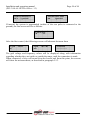
Connection of the system to the grid
The two-line LCD display is located on the front panel, and shows the following:
The operating status of the inverter and statistical data;
Service messages for the operator;
Alarm and fault messages.
During regular operation, the display will cycle through available data. The screens
change every 5 seconds, or can be changed manually by pressing the UP and DOWN
keys (see Fig. 20).
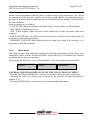
These 2 screens are displayed at inverter start-up:
POWER-ONE
Starting up...
Please wait
One of the following two screens may be displayed while waiting for the connection,
depending on conditions:
Vac absent
Awaiting sun
While the system is checking the grid connection, the yellow LED next to the display
will be lit up constantly and the green LED will be flashing;
When waiting for solar radiation ("Waiting sun"), the yellow LED will be off while
the green LED will be flashing.
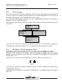
As soon as the "Vac absent" and "Awaiting sun" conditions have been successfully
satisfied, the inverter will start the inverter connection procedure. Depending on the
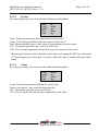
type of grounding, different controls will be performed and different screens shown.
If the system is grounded (one of the two poles is connected to the ground) the first
screens will be as follows
Installation and operating manual
(PVI-3.8/4.6-I-OUTD-xx Rev.: 1.3)
Page 54 of 94
GND ISO SELFTEST
RUN … Vgnd 130V
GND ISO SELFTEST
OK
Vgnd 130V
If instead, the system is ungrounded (neither of the two poles is connected to the
ground), the first screen will be as follows:
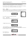
Control grid:
30
sec
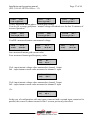
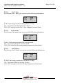
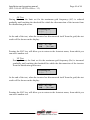
After the first control, the following screens will alternate between them
V grid
K
223.8 V
Fgrid
OK
50.17 Hz
Connection
........................
The grid voltage and frequency values will be displayed along with information
regarding whether they are inside or outside the range, until the connection is made
When connected, a beep will sound from the buzzer and from this point, the screens
will show the measurements, as described in paragraph 5.5.3.
Installation and operating manual
(PVI-3.8/4.6-I-OUTD-xx Rev.: 1.3)
Page 55 of 94
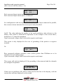
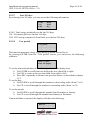
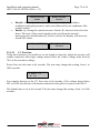
5.5.2
Error messages
After the connection has been established, if the inverter
er detects incorrect information
in the test cycle, the system will interrupt this cycle, indicating the error code. Refer to
the table in paragraph 5.4 for information on error codes.
To customize the display message, use the programming procedure described
describ in
chapter 5.5.6.14 “Alarm Message”.
Until the error has been solved, the system will continue to show the following cycle
of screens:
ERROR
Code ……..
Type OUTD
Part No………
In range
Custom msg………
S/N ………..……..
Firmware……
In range
Once the error has been rectified, the inverter resets all of the function in progress,
restarting the connection (chapter 5.5.1, Connection of the system to the grid)
5.5.3
First phase - Electric parameter check
GENERAL QUESTIONS RELATING TO THE USE OF DISPLAY KEYS:
During regular operation, the display will cycle through available data. The screens
change every 5 seconds or can be alternated manually by pressing the UP and DOWN
keys (see Fig. 20).
In any case, to return to the previous menu, press the ESC key (see
see Fig. 20).
20
Fig. 21
Activation of cyclical scrolling is indicated by the 2 arrows in the top left-hand
left
corner
of the display (Fig. 21).
Scrolling can be blocked by pressing the ENTER key. A padlock symbol will appear
(Fig. 21).
Installation and operating manual
(PVI-3.8/4.6-I-OUTD-xx Rev.: 1.3)
Page 56 of 94
If the measures performed previously, in chapter .5.5.1, are found to give a positive
result then the system will continue with other checks. The following screens repeat
cyclically as described in the paragraph “GENERAL QUESTIONS REGARDING
THE USE OF DISPLAY KEYS”.
TypeOUTD
PN------------
Type and p/n of the inverter
S/N---------xxxxxx
FW rel. C.0.1.1
Indicates the serial number of the inverter and the firmware revision level
E-da 0 Wh
$-da 0.0 EUR
E-da : Daily quantity of energy produced.
$-da: Daily energy savings. The value is expressed in the set currency.
E-tot ------------E-par 0 KWh EUR
E-tot : Total energy produced since first installation
E-par: Partial energy produced during the period selected by us
P-out 0 W
T-boost1 - °C
P-out : measured instant output power value
In the second line of the display, only the higher of the two temperatures is shown:
T-boost1: booster channel 1 switching device temperature
T-boost2: booster channel 2 switching device temperature
Ppk
W
Ppk-Day ………...W
Ppk: maximum peak power value achieved since the "partial" function was activated.
Ppk-Day: indicates the maximum peak power value achieved during the day. The
meter is reset when the unit is shut down.
Installation and operating manual
(PVI-3.8/4.6-I-OUTD-xx Rev.: 1.3)
VoutR
230 V
Vout AvgR 230 V
Page 57 of 94
VoutS
230 V
Vout AvgS 230 V
VoutT
230 V
Vout AvgT 230 V
VoutX: measured instant phase / neutral grid voltage
Vout AvgX: average grid phase / neutral voltage calculated over the last 10 minutes of
inverter operation.
VoutRS
400 V
Vout AvgR 230 V
VoutST
400 V
Vout AvgS 230 V
VoutTR
400 V
Vout AvgT 230 V
VoutXX: measured instant concatenated voltage
IoutR
FoutR
5.6 A
50.01 Hz
IoutS
FoutS
5.5 A
50.01 Hz
IoutS
FoutS
5.8 A
50.01 Hz
Iout: measured instant grid current value
Fout: measured instant grid frequency value
Vin1
I in1
0V
0.0 A
Vin1: input instant voltage value measured at channel 1 input
Iin1 : input instant current value measured at channel 1 input
Vin2
I in2
0V
0.0 A
Vin2: input instant voltage value measured at channel 2 input
Iin2 : input instant current value measured at channel 2 input
Or:
Vin
I in
0V
0.0 A
In the case of configuration with one input connected and a second input connected in
parallel, this screen is shown instead of the 2 screens previously described.
Installation and operating manual
(PVI-3.8/4.6-I-OUTD-xx Rev.: 1.3)
Pin 1
Pin 2
Page 58 of 94
0W
0W
Pin1: measured input instant power of channel 1
Pin2: measured input instant power of channel 2
Pin
0W
In a configuration with one input connected and a second input connected in parallel,
this screen is shown instead of the screen previously described
IsoOF
Vgnd
5.5
200V
IsoOF: The value indicates the quality of the earth insulation, with reference to the
unitary value which is sufficient for operation. In the example of the screen above,
insulation is 5.5 times the minimum.
Vgnd: measured voltage value between the negative earth input.
This screen is only displayed in the case of grounding of the positive or negative
terminal.
Or:
Riso
Vgnd
20 M
200 V
Riso: measured isolation resistance value (values greater than 20Mohm are to be
considered out of reading range).
Vgnd: measured voltage value between the negative earth input.
This screen will only be displayed if the grounding is disconnected and the channels
are configured in parallel.
Inverter OK
Wed 17 May 20:10
If there are no problems, OK will be written on the first line of the display, with the
current date and time displayed on the second.
Installation and operating manual
(PVI-3.8/4.6-I-OUTD-xx Rev.: 1.3)
Page 59 of 94
In the event of problems with the clock or other inverter parts which are "not vital to
the operation of the inverter" (insofar as the unit is still capable of producing energy),
the type of problem will be indicated on the second line of the display, in the place of
the date and time.
Error messages are as follows:
- CLOCK FAIL indicates problems with the clock, it is necessary to call assistance
- BATTERY LOW battery is low
- ADJ. TIME appears when the unit is first turned on, or after the battery has been
replaced
- FAN FAILURE does not affect the correct operation of the inverter; replace the fan
at the first convenient opportunity
- MEMORY FAILURE: data collected can no longer be stored. For recovery, it is
necessary to call for assistance.
5.5.4
Main menu
Once the previous grid connection phases and electrical parameter checks have been
completed, other screens become available which allows us to monitor the inverter
operation from various viewpoints.
By pressing the ESC key (1st key from display) 3 new screens become accessible:
Statistics
Settings
Information
GENERAL QUESTIONS RELATING TO THE USE OF DISPLAY KEYS:
- Pressing the UP and DOWN keys, allows you to move from one entry to the next.
- Pressing the ESC key allows you to return to the previous session described in
chapter 5.5.3.
- Pressing ENTER allows you to access the corresponding sub-menu
Installation and operating manual
(PVI-3.8/4.6-I-OUTD-xx Rev.: 1.3)
Page 60 of 94
5.5.5
Statistics
Select the STATISTICS menu to display the following submenu:
Total
Partial
Today
Last 7 days
Last month
Last 30 days
Last 365 days
User period
The display only shows 2 lines, so to scroll through the entries or open the
corresponding submenus, use the keys at the side of the display as described in
paragraph: 5.5.3, GENERAL QUESTIONS REGARDING THE USE OF DISPLAY
KEYS.
The selected entry will be highlighted by an arrow on the left-hand side of the display,
as shown in the figure below:
5.5.5.1
Total
By selecting Total, you can access the following information:
Time
E-tot
Val.
CO2
Time: Lifetime operation time
E-tot: Total energy produced
Val. : Economic gain
CO2: CO2 saving compared to fossil fuels
h
KWh
EUR
Kg
Installation and operating manual
(PVI-3.8/4.6-I-OUTD-xx Rev.: 1.3)
Page 61 of 94
5.5.5.2
Partial
By selecting Partial, you can access the following information:
Time
E-par
Ppeak
Val.
CO2
h
KWh
W
EUR
Kg
Time: Total operation time since the count was last reset *
E-par: Total energy produced since the count was last reset*
Peak: Measured peak power value since the partial meter was activated
Val. : Economic gain since the count was last reset*
CO2: CO2 saving compared to fossil fuels since the count was last reset*
* Resetting all meters in this submenu can be done be keeping the ESC key depressed
(4th from display) for more than 3 seconds. After this time, a sound will repeat three
times.
5.5.5.3
Today
By selecting Today, you can access the following information:
E-tod
Ppeak
Val.
CO2
KWh
W
EUR
Kg
E-tod: Total energy produced during the current day
Ppeak: peak power value reached during the day
Val. : Economic gain during the current day
CO2: CO2 saving for the current day compared to fossil fuels
Installation and operating manual
(PVI-3.8/4.6-I-OUTD-xx Rev.: 1.3)
Page 62 of 94
5.5.5.4
Last 7 days
By selecting Last 7 days, you can access the following information:
E-7d
Val.
CO2
KWh
EUR
Kg
E-7d: Total energy produced during the last 7 days
Val. : Economic gain during the last 7 days
CO2: CO2 saving over the last 7 days compared to fossil fuels
5.5.5.5
Last month
By selecting Last month, you can access the following information:
E-mon
KWh
Val.
EUR
CO2
Kg
E-mon: Total energy produced the current month
Val. : Economic gain in the current month
CO2: CO2 saving in the current month compared to fossil fuels.
5.5.5.6
Last 30 days
By selecting Last 30 days, you can access the following information:
E-30d
Val.
CO2
KWh
EUR
Kg
E-30d: Total energy produced over the last 30 days
Val. : Economic gain over the last 30 days
CO2: CO2 saving over the last 30 days compared to fossil fuels.
Installation and operating manual
(PVI-3.8/4.6-I-OUTD-xx Rev.: 1.3)
Page 63 of 94
5.5.5.7
Last 365 days
By selecting Last 365 days, you can access the following information:
E-365
Val.
CO2
KWh
EUR
Kg
E-365: Total energy produced over the last 365 days
Val. : Economic gain over the last 365 days
CO2: CO2 saving compared to fossil fuels over the last 365 days
5.5.5.8
User period
User period
This function measures energy saving during a period selected by us.
By pressing ENTER from the "User period" screen, you can access the following
submenu:
Start 23 June
End 28 August
To set the start and end dates of the chosen period, use the display keys:
Use ENTER to scroll from one field to the next (from left to right)
Use ESC to return to the previous field (from right to left)
Press ESC repeatedly to return to the previous menus, as described in chapter
5.5.3
To set the day:
Use DOWN to scroll through the numbers in descending order (from 31 to 1)
Use UP to scroll through the numbers in ascending order (from 1 to 31)
To set the month:
Use DOWN to scroll through the months from December to January
Use UP to scroll through the months from January to December
If an invalid date is entered, the display will show the following:
Data err
Installation and operating manual
(PVI-3.8/4.6-I-OUTD-xx Rev.: 1.3)
Page 64 of 94
5.5.6
Settings
If you select SETTINGS from the Main menu (chapter 5.5.4), the first screen will
appear on the display, concerning the password:
Password
****
Password
0000
The default password is 0000. It can be changed using the display keys in the usual
way:
Use ENTER to scroll from one figure to another (from left to right)
Use ESC to return to the previous figure (from right to left)
Press ESC repeatedly to return to the previous menus, as described in
chapt.5.5.3
Use DOWN to scroll through the numbers in descending order (from 9 to 0)
Use UP to scroll through the numbers in ascending order (from 0 to 9)
After having entered the correct password, press ENTER to access to the different
information saved in this section:
Address
Display settings
Service
New Password
Currency
Date/Time
Language
Vstart
Autotests
Alarm
Remote control
UV Prot.time
MPPT
Alarm Message
The display only shows 2 lines, so to scroll through the entries and access each of the
submenus, use the UP and DOWN buttons.
Installation and operating manual
(PVI-3.8/4.6-I-OUTD-xx Rev.: 1.3)
Page 65 of 94
GENERAL QUESTIONS REGARDING READING THE DISPLAY.
The selected entry will be highlighted by an arrow on the left-hand side of the display.
Once the chosen entry is selected, press ENTER to enter its submenu.
5.5.6.1
Address
Using this function, you can set the addresses for the communication of individual
inverters connected to the system on the RS485 line. The numbers assigned can go
from 2 to 63. Use the UP and DOWN keys to scroll through the numbers.
New Address
63
The ‘AUTO’ selection is not usable at the moment
AUTO
2
3
…..
…..
62
64
AUTO
5.5.6.2
Imp. Display
This function allows you to set the display characteristics:
Light
Contrast
Buzzer
1) Light: display light setting:
Mode
Intensity
- With the MODE key, it is possible to control the display backlighting.
After selecting the Mode entry with the arrow and pressing ENTER, you will access
the following submenu. The next screen is:
ON
OFF
Auto
ON : Light always on
OFF : Light always off
Installation and operating manual
(PVI-3.8/4.6-I-OUTD-xx Rev.: 1.3)
Page 66 of 94
AUTO: Automatic light management. The light turns on every time a key is pressed,
and remains on for 30 seconds before gradually turning itself off.
- The INTENSITY key allows for the regulation of backlight intensity on a scale of 1
to 9
2) Contrast : Display light contrast
The scale of the display's light tones go from 0 to 9.
To select the number, press the UP and DOWN keys to scroll and then ENTER to
confirm your choice.
3) Buzzer: key tone setting
Selecting:
ON : key tones are on
OFF : key tones are off
5.5.6.3
Service
Only installation staff may access this function. A dedicated password, only supplied
by Power-One is necessary to gain access.
5.5.6.4
New password
This function is used to change the default password, 0000.
To enter your own personal code, the display keys must be used in the following way:
Use ENTER to scroll from one digit to another (from left to right)
Use ESC to return to the previous digit (from right to left)
Press ESC repeatedly to return to the previous menus, as described in chapter
5.5.3
Use DOWN to scroll through the numbers in descending order (from 9 to 0)
Use UP to scroll through the numbers in ascending order (from 0 to 9)
5.5.6.5
Currency
This function regards the energy output earnings.
Name
EUR
Val/KWh 00.50
Name: set the desired currency using the keys in the same way. The default currency is
the Euro.
Val/KWh: indicates the cost of 1 KWh expressed in the set currency. The default
setting is 0.50 Euros.
Installation and operating manual
(PVI-3.8/4.6-I-OUTD-xx Rev.: 1.3)
Page 67 of 94
5.5.6.6
Date/Time
The time and date can be modified from this section, if necessary.
Time 14:21
Date 17 May 2006
5.5.6.7
Language
It is possible to set your national language or English.
English
Italian
5.5.6.8
START-UP Voltage
The start-up voltage can be adjusted (if they are configured independently) also
separately for both channels in order to tailor it to the needs of the system. The voltage
range is from 120V to 350V. The default setting for Aurora is 200V. This parameter
may be varied by using the display keys.
Set
VStart
200V
5.5.6.9
Autotest Operation
In accordance with the “guide for connection to the ENEL power supply distribution
grid”, the autotest can be launched through the menu on the display or by using an
RS485/USB converter and the Aurora Communicator software (see paragraph 5.6 for
further details).
The following conditions are necessary for the Autotest to be performed:
You must have set the ENEL grid standard.
The inverter must be connected to the grid in a way that allows simulating a
disconnection condition.
Do not carry out any operation during the test execution phase.
Check that the device is connected to the grid in a stable way
Follow the procedure below in order to perform Autotest:
Access the menu SETTINGS > Autotest
In the section of the menu dedicated to the Autotest, the type of test that the
device must start may be selected from the following:
OV Test
Disconnection from distribution grid due to “Overvoltage”
UV Test
Disconnection from distribution grid due to “Undervoltage”
Installation and operating manual
(PVI-3.8/4.6-I-OUTD-xx Rev.: 1.3)
Page 68 of 94
OF Test
Disconnection from distribution grid due to “Maximum frequency”
UF Test
Disconnection from distribution grid due to “Minimum frequency”
OV Test
During this test, the limit set for the maximum grid voltage (AC) is reduced gradually
until reaching the threshold for which the disconnection of the inverter from the
distribution grid occurs.
Performing test
……….
At the end of the test, when the inverter has disconnected itself from the grid, the test
result will be shown on the display:
Test
OK
V= …. V
T= ….ms
Pressing the ESC key will allow you to return to the Autotest menu, from which you
can select another test.
UV Test
During this test, the limit set for the maximum grid voltage (AC) is increased
gradually until reaching the threshold for which the disconnection of the inverter from
the distribution grid occurs.
Performing test
……….
At the end of the test, when the inverter has disconnected itself from the grid, the test
result will be shown on the display:
Test
OK
V= …. V
T= ….ms
Pressing the ESC key will allow you to return to the Autotest menu, from which you
can select another test.
Installation and operating manual
(PVI-3.8/4.6-I-OUTD-xx Rev.: 1.3)
Page 69 of 94
OF Test
During this test, the limit set for the maximum grid frequency (AC) is reduced
gradually until reaching the threshold for which the disconnection of the inverter from
the distribution grid occurs.
Performing test
……….
At the end of the test, when the inverter has disconnected itself from the grid, the test
result will be shown on the display:
Test
OK
F=…. Hz
T= ….ms
Pressing the ESC key will allow you to return to the Autotest menu, from which you
can select another test.
UF Test
During this test, the limit set for the maximum grid frequency (Hz) is increased
gradually until reaching the threshold for which the disconnection of the inverter
from the distribution grid occurs.
Performing test
……….
At the end of the test, when the inverter has disconnected itself from the grid, the test
result will be shown on the display:
Test
OK
F=…. Hz
T= ….ms
Pressing the ESC key will allow you to return to the Autotest menu, from which you
can select another test.
Installation and operating manual
(PVI-3.8/4.6-I-OUTD-xx Rev.: 1.3)
Page 70 of 94
5.5.6.10
Alarm
The inverter is equipped with an alarm system which allows for the switchover of a
relay contact (available both as a contact normally set open - N.O. - and as a contact
normally set closed– N.C.). The relay contacts are accessible from the front cover as
shown in Error! Reference source not found.. This contact can be used, for example,
to activate an acoustic or visual alarm. In any case, the contact voltage/current rating
of 230V/1A must not be exceeded.
Fig. 22 - Alarm contact terminal block
This function can activate 4 different modes of alarm. By pressing the ENTER key,
you can access the following submenu:
Production
Alarm
Alarm (conf.)
Twilight
The selected entry is highlighted by an arrow on the left-hand side of the display. Use
the UP/DOWN keys to change your selection and the ENTER key to confirm.
•
PRODUCTION: the relay is only activated when the inverter is connected to
the grid.
For example, if the N.O. (or N.C.) contact is chosen, the contact will remain open
(closed) until the inverter is connected to the grid; once the inverter is connected and
begins to transfer power, the relay will switch its status to closed (open). When the
inverter disconnects itself from the grid, the relay contact returns to its rest position,
i.e. open (closed).
•
ALARM: the relay is activated in the case of alarm (code E).
Installation and operating manual
(PVI-3.8/4.6-I-OUTD-xx Rev.: 1.3)
Page 71 of 94
For example, if the N.O. (or N.C.) contact is chosen, it will remain open (closed) until
an error occurs in the inverter (IT DOES NOT SWITCH OVER IN CASE OF
WARNING or code W); once an error has occurred in the inverter, the relay switches
its status to closed (open). The contract remains in this position, i.e. switched over
with respect to its rest position, until normal operation, i.e. operation in parallel with
the grid, is restored.
•
ALARM (conf.): the relay switches over in the event of alarms (code E) or
warnings (code W) chosen from a list by the user (the list may also show
selections which are not designed for the specific model, consult table 5.4
when choosing).
For example, if the N.O. (or N.C.) contact is chosen, the contact will remain open
(closed) until in the inverter an error occurs or warning is issued from those selected;
once in the inverter the error has occurred or warning issued, the relay switches its
status to closed (open). The contract remains in this position, i.e. switched over with
respect to its rest position, until the error code or warning is solved.
•
TWILIGHT: the relay switches only when the input voltage set for grid
connection is exceeded.
For example, if the N.O. (or N.C.) contact is chosen, the contact will remain open
(closed) until the inverter reaches a Vin which is greater than that selected for grid
connection. The contact will remain in this position, i.e. switched over with respect to
its rest position, for the time the inverter is on (even if disconnected from the grid).
This mode is useful for disconnecting any large output transformers which may incur
large levels of consumption during the night.
To select the alarm contact operating mode, access the Alarm submenu from the
Settings menu, select the desired operating mode by using the UP and DOWN arrows,
and push the ENTER key to confirm your choice.
5.5.6.11
Remote Control
This setting is used to enable/disable the inverter remote switch-off function through
the appropriate control signal (on the signal terminal box).
If you choose to enable this option, it will be possible to control Aurora’s ON/OFF
function by connecting a relay contact or switch between the +R and –R contacts.
Installation and operating manual
(PVI-3.8/4.6-I-OUTD-xx Rev.: 1.3)
Remote ON/OFF
Enable
•
•
Page 72 of 94
Remote ON/OFF
Disable
Disable: Aurora operation is automatic, depending on the radiation
conditions (and grid presence), and is not influenced by the condition of the
control contact.
Enable: by closing the contact between +R and –R, Aurora is forced to shut
down. The state of the control signal can be read from the internal
microprocessor and alternatively, if this is closed, the display will show the
forced OFF status.
Remote OFF
Waiting Rem.ON…
to restart
5.5.6.12
UV Prot.time
Using this function it is possible to set the length of time for which the inverter will
remain connected, after input voltage drops below the Under Voltage limit fixed at
70% of the activation voltage.
Power-One sets this time at 60 seconds. The user may change this setting, from 1 to
3600 seconds.
T Protez. UV
60 secs
For example, having set the UV Prot. time at 60 seconds, if Vin voltage drops below
90V at 09.00, the inverter will remain connected to the grid (at 0 power) until 09.01.
The default time is set at 60 seconds. The user may change this setting, from 1 to 3600
seconds.
Installation and operating manual
(PVI-3.8/4.6-I-OUTD-xx Rev.: 1.3)
Page 73 of 94
5.5.6.13
MPPT
This function is used in order to set the parameters for the Maximum Power Point
Tracker function.
MPPT Amplitude: this setting allows you to choose the amplitude of disturbance
introduced in DC in order to establish the optimal work point. There are 3 choices
(LOW, MEDIUM, HIGH). The default setting is MEDIUM.
MPPT Amplitude
Multi-Max Scan
MPPT Amplitude
Low
You can enable or disable the scan function to identify the maximum multiples.
MPPT scan En/Dis
Enable
The time interval for system maximum multiples scans can be set using this function.
The default setting is 15 minutes.
Scan Interval
15 min
You may also decide to perform a manually scan, by using the specific control
Manual Scan
5.5.6.14
Alarm Message
Follow the procedure described below in order to program the error message that will
be shown on the display:
Alarm Message
Pressing the ENTER key will allow you to access the relevant submenu
Installation and operating manual
(PVI-3.8/4.6-I-OUTD-xx Rev.: 1.3)
Enable / Disable
Compose message
Page 74 of 94
Enable Msg
Disable Msg
Move the selection arrow using the UP and DOWN keys, press ENTER to navigate
the submenus or select the functions.
Once the personalized message has been enabled, you must compose the message
itself.
Compose Message message
Upon selecting Compose Message you will be able to write the first line of the
message.
Message line 1:
----------------
Message line 2:
----------------
The maximum numbers of characters is 16. Pressing the Enter key 17 times will allow
you to move to the second line.
To write the message, use the display keys, following procedure below:
Use the ENTER key scroll from one position to the next (from left to right)
Use the ESC key to return to the previous position (from right to left)
Press the ESC key several times to return to previous menus, as described in
chapter 5.5.3
Use the UP key to scroll through the numbers, letters and symbols in
ascending order
Use the DOWN key to scroll through the numbers, letters and symbols in
descending order
Installation and operating manual
(PVI-3.8/4.6-I-OUTD-xx Rev.: 1.3)
Page 75 of 94
5.5.7
Info
From this menu, you can access all the Aurora inverter data and display the grid
standard and the chosen language through the specific selectors.
The menu is structured as follows:
Product ID (part number)
Serial No. (serial number, week, year of production)
Firmware (firmware revision level)
Country Selector
Current value (currently set standard)
New value (standard that will be set upon re-start if the switches are switched
over)
Set new (manually set the new selected standard)
Residual time (for which it is still possible to change the applied standard)
The last menu allows you to see which standard is currently set in the inverter (Current
Value); which will be applied to the next start-up (New Value) after acting on the
selectors; manually set the new value (Set New Value); and set the time remaining for
making changes to the applied standard (Residual Time).
When the Residual Time is finished, it will no longer be possible to make changes to
the applied standard and an unblocking code will be needed (see paragraph 3.4.7). The
time period is 24 hours of operation with the inverter connected to the power supply
grid.
Installation and operating manual
(PVI-3.8/4.6-I-OUTD-xx Rev.: 1.3)
5.6
Page 76 of 94
AUTOTEST PROCEDURE BY USING AURORA COMMUNICATOR
The Autotest procedure can be carried out by using the Aurora Communicator
software, included in the CD provided.
To carry out autotest, follow the procedure below:
-
Install the Aurora Communicator software on your PC.
Connect the inverter to the PC by using the RS485/UBS converter
Start-up the Aurora Communicator software
The start-up screen will be displayed:
Installation and operating manual
(PVI-3.8/4.6-I-OUTD-xx Rev.: 1.3)
Page 77 of 94
•
Click on Configuration > Configure Inverter
•
In the “Configure inverter” window, click on “Scan”: all the connected
inverters will be shown under “Inverter list”. Select the inverter upon which
the autotest is to be performed and press “OK”
Installation and operating manual
(PVI-3.8/4.6-I-OUTD-xx Rev.: 1.3)
Page 78 of 94
•
On the start-up page, the selected inverter will now be shown. Right-click on
the S/N of the inverter and click “Autotest”.
•
Select the test or tests of interest (check max voltage, check min voltage,
check max frequency, check min frequency), checking off the corresponding
check boxes and clicking on the start button to launch the test.
Installation and operating manual
(PVI-3.8/4.6-I-OUTD-xx Rev.: 1.3)
Page 79 of 94
•
The inverter will perform all of the tests selected in sequence, displaying its
progress
•
At the end of each test, the “wait grid” screen will appear, while awaiting the
inverter to re-connect to the grid.
Installation and operating manual
(PVI-3.8/4.6-I-OUTD-xx Rev.: 1.3)
Page 80 of 94
When the Aurora Communicator has completed all of the requested tests, a summary
screen will appear reporting the results of the various tests.
NOTE: Click on the Export button to export the test results onto your PC in
.csv or .txt format
Installation and operating manual
(PVI-3.8/4.6-I-OUTD-xx Rev.: 1.3)
6
6.1
Page 81 of 94
DATA CHECK AND COMMUNICATION
Connection through RS-485 serial port or RJ45 connectors
6.1.1
RS-485 serial port
The RS-485 serial port uses a three-wire cable: two for signals and a third for ground
connection. The cable should be passed through the holes located on the bottom of the
inverter, closed with airtight plugs (see
Fig. 23).
The supplied cable gland must be installed into the appropriate hole (replacing one of
the caps).
Fig. 23 - Cable routing for RS-485 connection
For ease of installation, the inverter is provided with two holes to differentiate the
input cable route from the output cable route when several units are connected in a
daisy chain as described below.
Once the cables have been passed through the cable gland, they are connected inside
the unit to the RS-485 terminal blocks which can be accessed by removing the front
cover. Refer to par. 3.4.2. for information on correct front cover removal and
reassembly.
The signal wires must be connected to the +T/R and –T/R terminals
The ground wire must be connected to the RTN terminal
Installation and operating manual
(PVI-3.8/4.6-I-OUTD-xx Rev.: 1.3)
Page 82 of 94
RJ45 No.1
RJ45 No.2
Fig. 24 - Terminals for connection to RS-485 and S2 switch
6.1.2
RJ45 connectors
Alternatively, the RS485 serial connection of the inverters, whether as single units or a
daisy chain, can be performed by means of RJ45 connectors (see
Fig. 24)
The wiring must be routed through the holes closed with airtight plugs, located on the
bottom of the inverter (see
Fig. 23). Input wiring passes through one hole and is assembled to one of the RJ45
connectors; output wiring passes through the other hole and is assembled to the RJ45
connector of the next unit.
It does not matter whether it is no.1 or no.2 insofar as, being connected in parallel, the
signals are the same.
RJ45 connectors
Pin
#
Signal
Name
1
Not Used
2
Not Used
3
+TR
4
+R
5
-TR
6
Description
+ Data Line (RS485 Communication)
Remote OFF Remote control (see
paragraph 5.5.6.10 for details).
- Data Line (RS485 Communication)
Not Used
Installation and operating manual
(PVI-3.8/4.6-I-OUTD-xx Rev.: 1.3)
7
8
6.1.3
RTN
Page 83 of 94
Signal Return (Common mass for logical
signals)
Not Used
Daisy chain
The RS-485 terminal block or RJ45 connectors can be used to connect a single
AURORA inverter or multiple inverters, connected in a daisy chain. The maximum
number of inverters that may be connection in a daisy chain is 62. The recommended
maximum length of this chain is 1000 meters.
If several inverters are connected in a daisy chain, it will be necessary to assign an
address to each. See paragraph 5.5.6.1 for information on changing addresses.
Furthermore, the last inverter in the chain must have the line termination contact of the
activated line (switch S2 -120Ω TERM in ON position) see
Fig. 24.
Each AURORA is provided with default address two (2) and with the S2 switch in the
OFF position.
In order to ensure optimum communication on the RS485 line, Power-One
recommends connecting the PVI-USB-RS485_232 adaptor between the first unit of
the daisy chain and the computer. See Fig. 25 for details. (RS485-USB Converter)
For this purpose, other equivalent devices found on the market may also be used, however,
since they have never been specifically tested, Power-One does not guarantee the correct
operation of the connection.
Please note that these devices may also require an external termination impedance, which is
not necessary for the Aurora PVI-USB-485_232.
The following diagram shows how to connect units in a daisy chain configuration.
Installation and operating manual
(PVI-3.8/4.6-I-OUTD-xx Rev.: 1.3)
Page 84 of 94
PC with RS232 port
(Sub-D 9 pin male)
nd
Last Aurora
st
2 Aurora
1 Aurora
(Sub-D 9 pin female)
PVI-USB-RS232_485
RS485 to USB Converter
RTN +T/R-T/R
(terminal block)
RTN +T/R -T/R
S2
switch
ON
RTN +T/R -T/R
Off
S2
switch
OFF
RTN +T/R -T/R
S2
switch
OFF
RS-485 cable
max. length = 1.000mt
max. inverter nodes = 31
Recommended RS-485 cable type:
On
LiYCY, 2x2x0,5mm (n.2 twisted
pairs) + shield
(terminal block)
RTN +T/R-T/R
Data-Logger
RS485 port
RS-485 cable (1pair + 1 conductor) +
shield
Block Diagram: RS-485 cabling
AURORA PVI-3.8/4.6-I-OUTD
Fig. 25 - Daisy chain connection
NOTE: when using an RS-485 connection, there may be up to 62 inverters
connected on the same chain. Choose any address between 2 and 63
NOTE: when using an RS-485 connection, if one or more inverters are
subsequently added to the system, remember to switch back to the OFF
position the system inverter switch that before was the last one in the system.
Installation and operating manual
(PVI-3.8/4.6-I-OUTD-xx Rev.: 1.3)
7
Page 85 of 94
TROUBLESHOOTING
The AURORA inverters conform to the standards predefined for their operation in
connection with a grid, for safety, and electromagnetic compatibility.
Before the product is delivered, several tests are successfully performed to check the
operation, protection devices, performance, and durability of the equipment.
These tests, together with Power-One quality guarantee system, ensure optimal
operation of AURORA.
If the inverter should malfunction, however, solve the problem as follows.
Work in safe conditions as described in chapter 3.5, checking that the connections
between AURORA, the photovoltaic field, and the distribution grid have been
made correctly.
Carefully observe which of the LEDs is flashing, and read the text on the display.
After having done this, follow the instructions in chapters 5.3, 5.4, 5.5. in order to
identify they kind of anomaly which is occurring.
If the instructions in this document do not help in eliminating the problem, contact the
help service or the installer (see the instructions in the following page).
Installation and operating manual
(PVI-3.8/4.6-I-OUTD-xx Rev.: 1.3)
Page 86 of 94
Before contacting the help service, we ask you to have to following information close
to hand in order to maximize the efficiency of the operation:
INFORMATION ON AURORA
NOTE: Information available directly from the LCD display
AURORA model?
Serial number?
Week of production?
Which LED is flashing?
Intermittent or steady light?
Which signals are shown on the display?
Brief description of the fault?
Have you noted if the fault can be reproduced?
If so, in what way?
Have you noted if the fault repeats itself cyclically?
If so, how often?
Was the fault present at the time of installation?
If so, has it worsened?
Describe the atmospheric conditions present at the time the fault appeared
INFORMATION on the Photovoltaic Field
Brand and model of photovoltaic panels
System structure
- maximum array voltage and current values
- number of strings in the array
- number of panels per string
Installation and operating manual
(PVI-3.8/4.6-I-OUTD-xx Rev.: 1.3)
8
8.1
Page 87 of 94
TECHNICAL SPECIFICATIONS
Input values
WARNING: the photovoltaic field and system wiring must be configured in
such a way that the PV input voltage is less than the maximum upper limit,
independent of the model, number and operating conditions of the chosen
photovoltaic panels.
As the panel voltage also depends on the operating temperature, the choice of
the number of panels per string must take into account the minimum ambient
temperature for that specific area (see table A).
WARNING: the inverter is provided with a linear output derating depending
on the input voltage, from 470 Vdc (100% output power) to 520 Vdc (0%
output power)
WARNING: the open circuit voltage of the photovoltaic panels is affected
by the ambient temperature (the open circuit voltage rises as temperature
drops) and it is necessary to ensure that the minimum expected temperature
for installation does not cause the panels to exceed their maximum upper
voltage limit of 520 Vdc. The table below is an example which indicates the
maximum voltage for each panel for typical panels of 36, 48, 60 and 72 cells,
depending on temperature (assuming a rated open circuit voltage of 0.6 Vdc
for a cell at 25°C and a temperature coefficient of -0.0023 V/°C. The table
thus shows the maximum number of panels that may be connected in series,
depending on the minimum operating temperature. Consult the panel
manufacturer for the correct temperature coefficient of Voc before calculating
the maximum voltage of the photovoltaic array.
Installation and operating manual
(PVI-3.8/4.6-I-OUTD-xx Rev.: 1.3)
Max. number of
panels
Max. number of
panels
Max. number of
panels
Panel voltage
25
21.6
24
28.8
18
36.0
14
43.2
12
20
22.0
24
29.4
18
36.7
14
44.0
12
15
22.4
23
29.9
17
37.4
14
44.9
12
10
22.8
23
30.5
17
38.1
14
45.7
11
5
23.3
22
31.0
17
38.8
13
46.5
11
0
23.7
22
31.6
16
39.5
13
47.3
11
-5
24.1
22
32.1
16
40.1
13
48.2
11
10
24.5
21
32.7
16
40.8
13
49.0
11
15
24.9
21
33.2
16
41.5
13
49.8
10
20
25.3
21
33.8
15
42.2
12
50.7
10
25
25.7
20
34.3
15
42.9
12
51.5
10
Table A
Panel voltage
Panel voltage
72-cell panel
Max. number of
panels
60-cell panel
Panel voltage
48-cell panel
Panel min.
temp. [°C]
36-cell panel
Page 88 of 94
Installation and operating manual
(PVI-3.8/4.6-I-OUTD-xx Rev.: 1.3)
(1
Page 89 of 94
Description
Value
PVI–3.8-OUTD
Value
PVI–4.6-OUTD
Maximum input power
4420 W
5260 W
Rated input power
4000 W
4840 W
Rated input voltage
330 Vdc
Max. absolute input
voltage
520 Vdc
Input voltage, MPPT
operating range
from 90 Vdc to 520 Vdc
Input voltage, MPPT
operating range at full
power
from 200 Vdc to 470 Vdc
Max short circuit
current (of each array)
15.6 Adc
17 Adc
Max. operating input
current (of each array)
12.5 Adc
14 Adc
Max. input power (of
each array)(1)
3000 W
PV ground fault
protection
Isolation detection system + PTC
Input channel
configuration (array)
Parallel / Independent (2)
) The total input power must remain within the max. recommended DC power value
The independent channel configuration cannot be used with positive grounding
setting
(2)
Installation and operating manual
(PVI-3.8/4.6-I-OUTD-xx Rev.: 1.3)
Page 90 of 94
NOTE: If the photovoltaic field connected to the inverter supplies an input
current which is greater than the maximum usable value, the inverter will not
be damaged as long as the input voltage is within the permitted range.
8.2
Output values
Description
Rated output power
Value
PVI–3.8-OUTD
Value
PVI–4.6-OUTD
3800 W
4600 W
Grid voltage, maximum
operating range
180 / 264 Vac
Grid voltage, rated
230V
Grid frequency,
maximum range
47 / 63 Hz
Grid frequency, rated
50Hz
Rated output current
16.5 A
20 A
Max. output current
18.2 A
(16 A for UK Version
G83/1)
22.5 A
Output over current
protection
20 A
25 A
8.3
Grid protection characteristics
Anti-islanding protection
Complies with:
Guide for connection to the ENEL
power supply distribution grid
VDE V 0126-1-1
Royal Decree RD1663/2000 of
Spain
UK G83/1
Installation and operating manual
(PVI-3.8/4.6-I-OUTD-xx Rev.: 1.3)
8.4
Page 91 of 94
General characteristics
Description
Value
PVI–3.8-OUTD
Value
PVI–4.6-OUTD
Maximum efficiency
96.5%
Internal consumption in
stand-by mode
<8W
Internal consumption at
night
<2W
Operating ambient
temperature
Environmental category
Pollution degree
Overvoltage category (in
compliance with IEC
62109-1
from -25°C to +60°C (*)
For outdoor use (Outdoor)
3
II (Input DC circuit)
III (Output AC circuit)
Level of casing
protection
IP65 / Nema 4X
Audible noise when
internal fan is operating
< 50 dbA @ 1m
Size (height x width x
depth):
Weight
712 x 325 x 222 mm
24 kg
Relative humidity
0 – 100 % condensation point
Working altitude
2000 meters max.
(*) Full power guaranteed up to Amb.T. = 50°C for PVI-4.6-I-OUTD or 60°C for PVI3.8-I-OUTD (provided that it is not exposed to direct solar radiation)
Installation and operating manual
(PVI-3.8/4.6-I-OUTD-xx Rev.: 1.3)
Page 92 of 94
98
97
Efficiency, %
96
95
94
93
200
Vdc
340
Vdc
416
92
91
0%
10%
20%
30%
40%
50%
60%
70%
80%
90%
100%
% of Rated Output Power
Fig. 26 - Efficiency curve PVI-3.8-OUTD
98
97
Efficiency, %
96
95
94
93
200
Vdc
340
Vdc
416
92
91
0%
10%
20%
30%
40%
50%
60%
70%
% of Rated Output Power
Fig. 27 - Efficiency curve PVI-4.6-OUTD
80%
90%
100%
Installation and operating manual
(PVI-3.8/4.6-I-OUTD-xx Rev.: 1.3)
8.5
Page 93 of 94
Power Derating
In order to ensure inverter operation in safe thermal and electrical conditions, the unit
automatically reduces power input to the grid.
Power derating may occur in two cases:
Reduction in power due to environmental conditions
The degree of power reduction, and the temperature at which it starts occurring, also
depend, besides ambient temperature, on many operating parameters, including, for
example, input voltage, grid voltage, and power available from the photovoltaic field.
AURORA, therefore, can reduce power during certain periods of the days according to
the value of these parameters.
However, AURORA guarantees maximum power up to an ambient temperature of
50°C for PVI-4.6-I-OUTD, and of 60°C for PVI-3.8-I-OUTD, provided that it is not
exposed to direct solar radiation.
Reduction in power due to input voltage
The chart shows the automatic reduction in power output when input or output voltage
is too high or too low.
Power Derating (parallel channels)
5000
Pout (W)
4000
PVI-4.6 full power + 10%
PVI-4.6 full power
PVI-3.8 full power + 10%
PVI-3.8 full power
3000
2000
1000
0
50
150
250
350
450
550
Vin (V)
Figure 28 – Derating curve compared to input voltage - Use of both channels
Installation and operating manual
(PVI-3.8/4.6-I-OUTD-xx Rev.: 1.3)
Page 94 of 94
Power Derating (single channel)
3000
2500
Pout (W)
2000
PVI-4.6/3.8
1500
1000
500
0
50
150
250
350
450
550
Vin (V)
Figure 29 – Derating curve compared to input voltage - use of only channel IN1
NOTE: The curves show a zone of non operation up to 90V; a linear
derating zone up to 170V (PVI-4.6), and 140V (PVI-3.8); a zone of constant
rated power; and a high-voltage derating starting at 470V. Actually, the lowvoltage operating zone depends on the setting of the minimum starting
voltage (200V default). Once the converter is switched on it will continue to
operate according to the curves, up to a minimum value of 70% of the set
starting voltage (i.e. with a default value of 200V, the converter will have a
minimum operating voltage of 140V).
Conditions for power reduction due to environmental conditions and input voltage
may occur at the same time but power reduction will always occur with reference to
the lower detected value.