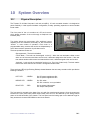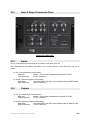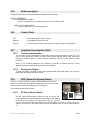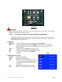
1
Teranex Video Computer
Installation and User Manual
(VC-6)
Version 3 (Rev. 2)
VIDEO COMPUTER
Teranex, Inc.
7800 Southland Blvd. • Suite 250
Orlando, FL 32809
Phone 407.858.6000 • Fax 407.858.6001
Copyright Notice
” Teranex, Inc. 2002
All rights reserved.
No part of this publication may be reproduced, transmitted, transcribed, stored in a retrieval system or
translated into any language in any form by any means without the prior written consent of Teranex, Inc.
Information in this manual is subject to change without notice and does not represent a commitment on
the part of the vendor.
Trademarks
Teranex and the Teranex logo are trademarks of Teranex, Inc.
All other product names are trademarks of their respective owners.
Printed in the U.S.A.
VC-6 UM V3-R2-020429.doc
Teranex VC-6 Installation and User Manual
ii
Contents
Section
page
1
INTRODUCTION..........................................................................................................1-1
2
MANUAL PURPOSE ....................................................................................................2-1
3
WARRANTY .................................................................................................................3-1
4
INJURY PRECAUTIONS .............................................................................................4-1
5
PRODUCT DAMAGE PRECAUTIONS ......................................................................5-1
6
STANDARDS, CERTIFICATIONS AND COMPLIANCES ......................................6-1
6.1
6.2
6.3
EMC STANDARDS......................................................................................................6-1
SAFETY STANDARDS ..................................................................................................6-1
ELECTROMAGNETIC COMPATIBILITY DIRECTIVE.........................................................6-1
7
PACKAGING.................................................................................................................7-1
8
UNPACKING.................................................................................................................8-1
9
INSTALLATION ...........................................................................................................9-1
9.1
PRE-INSTALLATION ...................................................................................................9-1
9.2
SITE REQUIREMENTS..................................................................................................9-1
9.2.1
Environmental ..................................................................................................9-1
9.2.2
Electrical ..........................................................................................................9-1
9.3
MOUNTING ................................................................................................................9-2
9.3.1
Rack Mounting..................................................................................................9-2
9.3.2
Desktop Placement ...........................................................................................9-2
9.4
ELECTRICAL POWER CONNECTION .............................................................................9-2
9.4.1
Standard IEC Connector...................................................................................9-2
9.4.2
Voltage Ratings ................................................................................................9-2
9.5
OPERATION THROUGH THE REMOTE INTERFACE (OPTIONAL) ......................................9-3
10
SYSTEM OVERVIEW ............................................................................................10-1
10.1 PHYSICAL DESCRIPTION ...........................................................................................10-1
10.2 INPUT & OUTPUT CONNECTION PANEL ....................................................................10-2
10.3 INPUTS ....................................................................................................................10-2
10.4 OUTPUTS .................................................................................................................10-2
10.5 REFERENCE INPUTS .................................................................................................10-3
10.6 CONTROL PORTS .....................................................................................................10-3
10.7 GRAPHICAL USER INTERFACE (GUI)........................................................................10-3
10.7.1 Touchscreen Information ................................................................................10-3
10.7.2 Cleaning the Display ......................................................................................10-3
10.8 POS (POWER ON SYSTEM) BOARD ..........................................................................10-3
10.8.1 DC Power Service Switch ...............................................................................10-3
10.8.2 Touchscreen On-Screen Display (OSD) System Settings .................................10-4
Teranex VC-6 Installation and User Manual
iii
11
START-UP MENU...................................................................................................11-1
11.1 AUTOLOAD OF DEFAULT APPLICATION ....................................................................11-1
11.2 START-UP MENU .....................................................................................................11-1
11.3 ACCESS KEY ENTRY, EDITING AND DELETION..........................................................11-2
11.3.1 Access Key Entry & Editing ............................................................................11-2
11.3.2 Deleting a Key from the Database ..................................................................11-3
11.4 UPGRADE FROM CD.................................................................................................11-3
11.5 CALIBRATE TOUCH SCREEN .....................................................................................11-5
11.6 EDIT IP ADDRESS ....................................................................................................11-5
11.7 DEMO MODE ...........................................................................................................11-5
11.8 SYSTEM INFO ..........................................................................................................11-6
12
SYSTEM SETUP MENU.........................................................................................12-1
12.1 KEYED PRODUCT OPTIONS.......................................................................................12-2
12.2 SET ETHERNET IP ADDRESS .....................................................................................12-2
12.3 CONVERSION DECISION LIST....................................................................................12-2
12.4 SYSTEM INFO ..........................................................................................................12-3
12.5 CALIBRATE TOUCH SCREEN .....................................................................................12-3
12.6 EXIT .......................................................................................................................12-3
12.7 OK .........................................................................................................................12-3
12.8 GPI SETUP TAB .......................................................................................................12-4
12.9 REFERENCE TAB ......................................................................................................12-5
12.10
AUDIO TAB .........................................................................................................12-6
12.10.1
Disable Audio Error Restart .......................................................................12-6
12.10.2
Input Source – SDI ONLY ...........................................................................12-7
12.11
TIMECODE TAB....................................................................................................12-8
12.12
DYNAMIC FILL SHADE TAB ..................................................................................12-9
13
USER PRESETS ......................................................................................................13-1
13.1
13.2
STORING CURRENT CONFIGURATION ........................................................................13-1
SAVE, RECALL OR RENAME A PRESET ......................................................................13-2
Teranex VC-6 Installation and User Manual
iv
1
Introduction
The Teranex Video Computer platform is a high-speed computing platform designed to accommodate
numerous software applications, primarily for video image processing.
By providing a system that is updateable, upgradeable, expandable, adaptable and user-friendly, Teranex
is setting a new performance standard for flexibility and cost effectiveness.
Current software applications offered by Teranex include:
Xantus – DTV Format and Standards Conversion
Xantus-one – Upconversion
Starfront – Pre-compression Processing and Noise Reduction
Star-up – Upconversion with Advanced Noise Reduction
Teranex VC-6 Installation and User Manual
1-1
2
Manual Purpose
This manual provides a reference guide for the Teranex Video Computer VC-6 (6-RU) chassis, and is
written for use by qualified technicians and operators of television equipment.
Included is information concerned with the installation and operation of the Teranex Video Computer.
Refer to your software application user manual(s) for details of operation and for features specific to that
application.
Teranex VC-6 Installation and User Manual
2-1
3
Warranty
The Teranex Video Computer includes a one-year warranty, which goes into effect from date of shipment
and extends 12 months thereafter.
This warranty covers manufacturer’s defects on parts and materials with Teranex’s option of repairing or
replacing any parts deemed or proved to be defective by Teranex during the warranty period.
Teranex will continue to support the unit with parts and service after expiration of the one-year warranty.
The cost of repairs and shipping after the warranty expiration, however, are not covered.
This warranty does not cover any defects caused by abuse, improper use or care, accidents, or any type
of system modification or repair by any individual or company other than an authorized Teranex
representative or Teranex certified technician.
Teranex makes no other warranties, expressed or implied. Teranex’s liability for any cause, including
breach of contract, breach of warranty, or negligence, with respect to products sold by Teranex, is limited
to repair or replacement by Teranex, at its sole discretion. This remedy is exclusive.
Under no circumstances shall Teranex be liable for any direct, indirect, special, incidental or
consequential damages, including loss of profits irrespective of whether Teranex has advanced notice of
the possibility of such damages.
Please see the Teranex Limited Warranty statement for complete warranty details.
Teranex VC-6 Installation and User Manual
3-1
4
Injury Precautions
WARNING!
If handled improperly, this unit can be hazardous under certain conditions. During servicing, this unit must
be handled with care to avoid high voltage electric shock.
Below are precautionary measures that must be considered before operating the
Teranex Video Computer.
˛ Do Not Operate Without Covers
To avoid electrical shock or fire hazard, do not operate this product without covers or panels
properly attached to unit. Servicing should be performed by qualified personnel only.
˛ Use Proper Power Cord
To avoid fire hazard, use only the power cord supplied with this product.
˛ Electrical Grounding
To avoid electrical shock, please make sure the unit is properly grounded with the AC grounding
conductor connected to a known electrical ground before making connections to the product’s
input or output terminals.
˛ Do Not Operate in Wet or Damp Conditions
To avoid electrical shock or fire hazard, do not operate this product in wet or damp conditions.
Teranex VC-6 Installation and User Manual
4-1
5
Product Damage Precautions
WARNING! -
Turn off AC power to the chassis before removing or
installing printed circuit assemblies, as this could result in serious damage to the
unit’s components.
Below is a list of precautionary measures that must be considered before
attempting to operate the Teranex Video Computer.
˛ Use Proper Power Source
Do not operate this product from a power source that supplies more or less than the voltage
specified for this product.
˛ Provide Proper Ventilation
To prevent product overheating, provide proper ventilation and do not obstruct front and side
ventilation areas of unit.
˛ Do Not Operate With Suspected Failures
If you suspect there is damage to this product, have it inspected by qualified service personnel.
Do not attempt to repair the failure even if you suspect it may be a minor problem.
˛ Use Power Cable Supplied (for USA ONLY)
An AC power cord is supplied with a standard IEC molded free socket on one end and a standard
3-pin plug on the other.
Teranex VC-6 Installation and User Manual
5-1
6
Standards, Certifications and
Compliances
The Teranex Video Computer has been tested and has been found to comply with the following CE, UL,
FCC, and TUV standards:
6.1
EMC standards
•
•
•
•
•
•
•
•
•
•
•
6.2
Safety standards
•
•
•
•
6.3
EN 50081-1 - Generic emissions standard
EN 55022/1998 - Limits and methods of measurement of radio disturbance
characteristics of information technology equipment, Class A
EN 50082-1 - Generic immunity standard
47CFR Part 15, Subpart B
107(e) Class A
109(g) Class A
CISPR22(1997) Class A
EN 61000-4-2 / 1995
EN 61000-4-3 / 1995
EN 61000-4-4 / 1995
EN 61000-4-5 / 1995
EN 61000-4-6 / 1996
EN 61000-4-11 / 1994
EN 60950 Safety of Information Technology Equipment, including electrical business
equipment
EN60950:1992 + A1:1993 + A2:1993 + A3:1995 + A4:1997 +A11:1997 NEMKOTSE(74-SEC) 207/94 Low-Voltage Directive 73/23/EEC of February 19, 1973 as
amended by 93/68/EEC.
UL 1419 Safety requirements for mains operated electronic and related apparatus for
household and similar general use.
CSA C22.2 No. 1-94 - Safety requirements for audio, video and similar electronic
equipment
Electromagnetic Compatibility Directive
These devices are for professional use only and comply with Part 15 of FCC rules. Operation is subject to
the following two conditions:
1. These devices may cause interference to Radio and TV receivers in residential areas.
2. These devices will accept any interference received, including interference that may cause
undesired operations.
Teranex VC-6 Installation and User Manual
6-1
7
Packaging
The Teranex Video Computer is shipped in a Teranex carton or crate, and should not be accepted if
packaging is clearly damaged or does not clearly display the authorized company logo, name or
materials.
Carefully open the carton and check for any obvious product damage incurred during shipping. If there is
any damage to the product, please contact your carrier immediately. If there are any shortages from the
packing list, please contact Teranex Customer Support immediately at 407-858-6000.
Teranex VC-6 Installation and User Manual
7-1
8
Unpacking
WARNING!
Two individuals are required to remove the unit from its shipping carton or
crate. One person should be on each side of the unit.
Do not grasp the unit’s front panel vent openings when removing the unit
from its shipping carton or crate. This may result in damage the front panel of
the unit.
1) Before opening the shipping case, position the case in a vertical manner where the opening of the
case remains face up.
2) When removing the unit from its case, secure both hands (one person on either side) under the
rack ears of the front panel where it screws into the base.
3) Carefully lift unit upward to remove and reposition horizontally on a flat surface.
4) Remove accessory box and chassis slide rail kit.
5) Please retain the carton or crate for use in the event that the unit must be returned to Teranex
for repairs.
Teranex VC-6 Installation and User Manual
8-1
9
Installation
9.1
Pre-Installation
Warning!
These servicing instructions are for use by trained personnel only. To reduce the risk of electric shock,
refer servicing to qualified personnel only.
Before mounting the VC-6 Video Computer, please verify that the circuit boards are seated correctly:
1. Loosen the four transit screws that secure the front panel to the chassis.
2. Pull the front panel forward and swing open to the left. This allows access to the main printed
circuit boards.
Note:
In some cases, systems are shipped with desiccant packs installed inside the chassis. Please
remove and discard them.
3. Remove the card retaining bracket (if installed) and store for future use.
4. Verify that the circuit boards are properly seated.
5. Check that the modules and associated cables are secure.
6. Ensure that the Service Switch on the internal POS board is turned “On.”
7. Close the front panel and secure the transit screws.
Note:
You must secure the four front-panel transit screws so that the unit will comply with applicable safety
regulations and emission standards. These safety regulations require a method of preventing access by
non-qualified personnel to circuitry.
9.2
Site Requirements
9.2.1
Environmental
The unit is cooled by forced air drawn in from the front of the machine, and expelled through
vents on the left-hand side. Consequently, there must be free passage for airflow at the left side
and front of the unit to allow for adequate ventilation. An ambient temperature should be
maintained between 10 deg C (45 deg F) and 30 deg C (95-deg F) at a relative humidity of 1090% (non-condensing).
9.2.2
Electrical
The rear panel is fitted with a standard IEC mains connector. A supply range of 110V to 240V,
47/63Hz, is required. (6A @110V; 3.5A @ 220V)
Note: The power supply has an auto-detecting feature for the main power source. A voltage
selector switch is not required.
Teranex VC-6 Installation and User Manual
9-1
9.3
Mounting
9.3.1
Rack Mounting
The chassis is designed for mounting into a standard 19-inch (483mm) rack and occupies a
vertical space of 6RU. A chassis slide kit is provided as standard accessory for easy installation
into the rack opening. Adequate space is required behind the chassis for clearance for the
connecting cables.
Warning!
Although the chassis is provided with standard front mounting ears for securing to the rack rails, it
is required that suitable shelf supports or slides (supplied) be used. Failure to install suitable
shelf supports or slides may result in equipment damage and/or personal injury.
9.3.2
Desktop Placement
The Video Computer is shipped with a set of plastic feet that may be attached to the bottom of the
unit for use on a desk or table. If your installation will be on a desk or table, please screw the
plastic feet into the bottom of the unit to protect the surface of the desk or table.
Warning!
Failure to secure the plastic feet shipped with the unit to the bottom of the unit for installation on a
desk or table may result in damage to the desk or table.
9.4
Electrical Power Connection
Warning!
The Teranex Video Computer must be grounded to avoid electrical shock. Failure to ground the
unit may result in equipment damage and/or personal injury. Particular attention should be given
to supply connections when connecting to power strips rather than direct connections to branch
circuits.
9.4.1
Standard IEC Connector
The rear panel is fitted with a standard IEC connector for A.C. mains supply of 110V to 240V (as
applicable), 47-63Hz.
9.4.2
Voltage Ratings
The power supply automatically adjusts for 110V to 240V operation. A voltage selector switch is
not required.
Warning!
To avoid electric shock, never remove the unit’s covers. There are no user-serviceable parts
inside. Refer servicing to qualified personnel. Failure to comply may result in equipment damage
and/or personal injury.
Teranex VC-6 Installation and User Manual
9-2
9.5
Operation through the Remote interface (Optional)
Teranex Remote Control Software is available as an option. Using the Ethernet port, you
may control the GUI via a customer-supplied computer. The Remote Control Software
allows the user to navigate the GUI screen using a mouse as a pointing device.
Requirements:
Teranex Remote Control Software is compatible with Windows NT, 2000, 98 and 95 Operating Systems.
Users may connect an Ethernet crossover cable (RJ45) directly from their Windows machine to the back
of the Teranex chassis, or insert the unit within a network (consult your system administrator).
Instructions:
For detailed installation instructions, please see the documentation provided with the Teranex Remote
Control Software CDROM, the Remote Control section of your user manual, or contact Teranex Customer
Support.
Teranex VC-6 Installation and User Manual
9-3
This page intentionally left blank.
Teranex VC-6 Installation and User Manual
9-4
10 System Overview
10.1
Physical Description
The Teranex VC-6 Video Computer is a 6-rack unit (6RU), 19” rack mountable chassis. It is designed to
permit flexibility in initial system hardware configuration, thereby permitting expansion to accommodate
future needs.
The front panel of the unit contains an LCD touch-screen,
which allows operation of the unit through a Graphical User
Interface (GUI).
Two knobs below the touchscreen offer additional control
capability and can substitute functionally for the touchscreen
“sliders” in most modes of operation. Each knob is a
programmable rotary encoder that can be set independently in
one of three modes of operation via pull-down menus.
The three operational modes are:
Deprogrammed – The knob is disabled.
Follow Mode – The knob can be assigned ‘on the fly.’ When the user activates a slider control
within one of the menus and then turns a knob, it becomes assigned to that function. If the user
then selects another slider control and retouches the knob, it will be assigned to the new function.
Assigned – Locks a knob to a particular function (e.g.- Proc Amp Video Level). The knob retains
this function even when the GUI screen is changed to another mode.
There are three LEDs (Light Emitting Diodes) situated between the two rotary encoders which provide the
following indications:
LEFT LED
- GREEN
On: DC power supplies are ON
Off: DC power supplies are OFF
MIDDLE LED
- GREEN
On: GUI active
Off: GUI not active, or not yet loaded
RIGHT LED
- RED
On: No output video present
Off: Output video present
The front panel is secured to the base of the unit with four captive transit screws. Once the screws are
loosened, the front panel easily slides forward away from the unit, still attached by two sliding internal
posts on the left hand side of the chassis. The front panel can then swing open on an attached hinge for
easy access to the internal CD-ROM drive and circuit boards.
Teranex VC-6 Installation and User Manual
10-1
10.2
Input & Output Connection Panel
Teranex VC-6 Rear Panel
10.3
Inputs
Four (4) inputs with active loop-through are provided on rear panel of the unit.
Note: Depending on the software application in use, certain connectors described below may not be
utilized.
2 x SDI, 10-bit Serial Digital Interface (BNC)
- Data Rate:
270Mb/s – Rec 601 with embedded audio per SMPTE 272M
- Input Impedance:
75-ohm, unbalanced
2 x HD-SDI, 10-bit Serial Digital Interface (BNC)
- Data Rates:
1.485 Gb/s SMPTE 292-1997 with embedded audio per SMPTE 299M
- Input Impedance:
75-ohm, unbalanced
10.4
Outputs
3 x SDI, 10-bit Serial Digital Interface (BNC)
- Data Rate:
270Mb/s – Rec 601 with embedded audio per SMPTE 272M
- Output Impedance:
75-ohm, unbalanced
3 x HD-SDI, 10-bit Serial Digital Interface (BNC)
- Data Rates:
1.485 Gb/s SMPTE 292-1997 with embedded audio per SMPTE 272M
- Output Impedance:
75-ohm unbalanced
Teranex VC-6 Installation and User Manual
10-2
10.5
Reference Inputs
Provides Inputs for the unit to be field locked to external reference signals.
ANALOG REFERENCE
1 x for analog Blackburst (BNC)
- 15k-ohm unbalanced, 1 Vp-p (passive loop-thru), Sync Format RS-170A
1x BNC for Tri-Level Sync (BNC)
- 75-ohm unbalanced, 1 Vp-p (Active pass-thru)
10.6
Control Ports
GPI:
3x GPI inputs (25-pin D-style, female)
Network:
1x 10/100BaseT Ethernet (RJ-45)
RS-232:
1 x RS-232 (9-Pin D-style, male) (contact Customer Support for information)
10.7
Graphical User Interface (GUI)
10.7.1
Touchscreen Information
The front panel of the unit features an active matrix LCD touch-screen display for easy use. The
GUI is a color display with a series of intuitive menu options featuring set up, input, output and
processing screens specific to each software application running on the Teranex Video
Computer.
Refer to your software application user manual(s) for details of features specific to each
application that are accessed via the Graphical User Interface.
10.7.2
Cleaning the Display
To clean the display, wipe with a damp cloth moistened with mild glass cleaner. Do not use a
paper towel, which may scratch the screen.
10.8
POS (Power On System) Board
The POS, or Power On System, board is located inside the chassis and
faces the user below the card cage after opening the front of the unit. (See
location in figure at right. See enlargement on next page.)
The POS Board serves two functions:
10.8.1
DC Power Service Switch
The DC Power Service Switch allows the user to turn the DC
power supplies on and off for purposes of servicing the unit without
turning off the AC breaker on the rear panel. The +3.3, +5, and
+12-volt LED indicators will illuminate then the Service Switch is turned on. When the Service
Switch is turned off, the AC Power LED will remain illuminated if the AC mains circuit breaker is
on.
Teranex VC-6 Installation and User Manual
10-3
POS Board
Warning!
When the DC Service Switch is turned off, AC power remains present at the inputs to the DC power
supplies and a hazardous condition may exist.
10.8.2
Touchscreen On-Screen Display (OSD) System Settings
Pressing the MENU push-button switch on the POS board will activate the Touchscreen OnScreen Display (OSD) menu, shown below. This menu provides the ability to manipulate the
display attributes of the touchscreen.
CONTROLS:
Brightness
Menu
Select
Neg
Pos
- Turn this variable resistor to control backlight (screen) brightness.
- Pressing this button will display the OSD Menu, shown below, on the touchscreen.
After making adjustments (if any) press Menu again to accept the changes and to
close the display.
- Toggles through the OSD Menu selections below.
- Decrements the value of the selected Menu parameter
- Increments the value of the selected Menu
parameter
OSD MENU SELECTIONS:
Contrast
Phase
Size
Vert
Horiz
- changes color saturation
- adjusts data sampling position
- for SVGA resolutions this adjusts the image
size (it may be necessary to adjust the image
horizontal position occasionally while using
this setting).
- adjusts the vertical position of the image
- adjusts the horizontal position of the image
Teranex VC-6 Installation and User Manual
10-4
11 START-UP MENU
11.1
Autoload of Default Application
The initial power-on sequence of the Video
Computer operating software will Autoload a
DEFAULT APPLICATION, or optionally allow
the operator to cancel the Autoload (see
screen at right) and proceed to the Start-Up
menu screen.
If the operator takes no action within 5
seconds of the appearance of the Autoload
screen, the software application defined as
the default product will automatically be
loaded and started.
If the operator cancels the Autoload process,
the Start-Up menu will be displayed (see
below).
11.2
Start-Up Menu
The Start-Up menu may be accessed by canceling the Autoload sequence (described above), or from the
System Setup menu within any software application.
The Start-Up menu offers an intuitive control layout, allowing access to various setup features of the
Teranex Video Computer:
•
Access Key Entry, Editing & Deletion
•
Selection of DEFAULT APPLICATION
•
Upgrade of System Software from CD
•
Calibration of the GUI Touchscreen
•
IP Address Assignment
•
Access to Demo Modes
•
Interrogation of Video Computer System
Information
Teranex VC-6 Installation and User Manual
11-1
11.3
Access Key Entry, Editing and Deletion
Configuration of the Video Computer is accomplished by entering a 16-digit Access Key, which defines
the software package(s) and optional features purchased. Your Access Key can be found in the shipping
documents enclosed with your unit.
During our pre-shipment Quality Assurance process, Teranex has entered the appropriate
Access Key required for your system configuration.
No action should be required by you upon delivery.
The Start-Up menu will store and display up to six (6)
Access Keys. The names displayed in each button (see
image at right) are user-definable via the Access Key Entry
procedure below. Each name may be up to six characters
in length.
The “Default” key is selected by pressing the circular button
next to the desired Access Key button. The default button
selected will turn black, as shown at right.
When changing the Default key, you will be prompted to
confirm your selection.
To invoke a key, press the rectangular button displaying the
desired key, and then press RUN.
11.3.1
Access Key Entry & Editing
If a new Access Key is required to activate new software packages or features, Teranex will
provide it to you. To enter the key, follow these steps:
1. Access the Start-Up menu. From
your application’s “Splash screen,”
press the SYSTEM SETUP button
in lower left area of the main GUI
menu, then press the EXIT button
on the System Setup menu. The
Start-Up menu, shown above, will
then be displayed.
2. Select one of the six Access Key
buttons and press the EDIT KEY
button, shown above. The “Edit
Key” screen, shown at right, will
then be displayed.
3. Touch the CLEAR KEY button.
4. Using the touchscreen “soft”
keyboard, enter the new 16-digit
Access Key provided by Teranex.
If you make an error during typing, press the BSP (backspace) key to erase incorrect
characters. You may also use the arrow keys (| }) to move the cursor to the desired position.
5. Optionally, you may name your Access Keys. With an Access Key displayed that you wish to
name, or immediately after entering a new Access Key, press CLEAR NAME and then EDIT
NAME. Using the soft keyboard, enter a name up to 6-characters long. Push OK. This will
simultaneously name the key and return you to the Start-Up menu.
NOTE: If you do not name your keys, they will be named and displayed in the Start-Up menu as
KEY1, KEY2, KEY3, etc., depending on the button position occupied.
Teranex VC-6 Installation and User Manual
11-2
11.3.2
Deleting a Key from the Database
On the Start-Up menu, select the Access Key to be deleted. Press the DELETE KEY button. You
will be prompted to confirm the deletion. Press OK in the prompt window to delete the key, or
press CANCEL to return to the Start-Up menu.
NOTE: A key designated as the Default Key cannot be deleted. To delete a Default Key, you
must first designate a different key as the Default Key. You may then delete the desired key.
11.4
Upgrade from CD
System operating software for Teranex products is distributed via CDROM. The Start-up menu provides
access to the “Upgrade from CD” menu.
Tools Needed: Phillips screwdriver to
loosen front panel screws.
Caution before beginning: Be careful that
you do NOT interrupt the update process
once it has begun, otherwise an
UNRECOVERABLE system condition may
occur.
SOFTWARE INSTALLATION:
1)
Loosen the captive screws on the front
of the Video Computer with a Phillips
screwdriver.
2)
Open the front of the unit.
3)
On the CDROM drive inside the unit,
press the “eject” button to eject the tray
or open the clamshell cover,
depending on CDROM drive type in your unit.
Start-Up Menu
4)
Place the supplied CD in the drive, and gently close the tray or clamshell cover, making sure the
disk remains seated. Wait a few seconds until the LED on the CDROM drive stops flashing.
5)
On the touch screen, press the “Upgrade
from CD” button (upper right).In the
“Upgrade” window, you may choose to
overwrite or save your existing presets in
the unit.
•
Overwriting presets returns the system
to factory values
•
Saving presets will retain any previous
preset values
•
Cancel the upgrade to return to the
Start-Up menu.
Teranex VC-6 Installation and User Manual
11-3
6)
Software installation will now begin.
•
Obsolete Directories and Files
will be removed.
•
Files will be updated and
verified automatically. During
this process, you will observe
that dots are displayed across
the screen one at a time. This
process may take as long a
twenty minutes, depending on
the number of files being
added and verified.
Note: The Firmware on Nevado Rev03 I/O
board and Resample Rev01 board will be
updated if required by the new software
release. If your unit is not equipped with
these board levels, a message will be
displayed stating that the “Target hardware does not support firmware upgrade.” (See above).
DO NOT TOUCH THE TOUCHSCREEN DURING THIS PROCESS.
7)
After the software has installed, you will be prompted to eject the CD and reboot (restart) the unit.
Cycle the power via the front service switch (POS board) or via the power switch on the rear of the
unit.
8)
The system will reboot and the yellow “autoload” countdown screen will be displayed.
9)
If you have been given a new Access Key to activate new features, please cancel the autoload
sequence, and enter the new Access Key now (see Section 11.3.1 above).
10)
Close the front panel and tighten the captive screws.
Teranex VC-6 Installation and User Manual
11-4
11.5
Calibrate Touch Screen
Opens a calibration screen, which allows the user to calibrate the performance of the touchscreen
display. The user is prompted to press target points in each corner and the center of the touchscreen.
The user must then CONFIRM the calibration be pressing a box in the center of the touchscreen.
If you feel that recalibration was not performed correctly, wait for the confirmation box to time-out, and
then repeat the calibration process.
Note: Calibration of the Touch Screen may also be initiated from any software application by choosing
this option from the System Setup menu.
11.6
Edit IP Address
Allows the user to set the Ethernet IP address
for the unit, and displays the current address.
The
default
factory
address
is
192.168.88.152. The unit comes standard
with an Ethernet port, which allows the unit to
be placed on a Local Area Network. This port
is used for remote control of the unit.
Pressing the Edit IP Address button activates
a touchscreen keyboard, permitting entry of a
new IP address for this unit.
After entering the new address, press OK to
invoke the setting and return to the Start-Up
menu.
Press CANCEL to return to the Start-Up
menu without modifying the IP address.
11.7
Demo Mode
Demo Mode allows the user to enable all options of the unit and to evaluate all current software
applications. This mode is very useful in allowing a user to try a processing option before purchasing it.
The output video will drop to black every 5-10
seconds while in Demo Mode.
After pressing the DEMO MODE button on
the Start-Up menu, a selection menu will be
displayed, allowing the user to choose the
desired software application.
The user may also press Cancel to return to
the Start-Up menu.
TO EXIT DEMO MODE, press S Y S T E M
SETUP then EXIT to close the application
and return to the Start-Up menu. You may
select an Access Key or another demo
mode.
Teranex VC-6 Installation and User Manual
11-5
11.8
System Info
Opens a system information window that provides the following information:
•
IP Address
•
MAC Address (for factory use only)
Press OK to close the Info Window.
NOTE: For more detailed System
Information, please see section 12.4 of this
manual.
Teranex VC-6 Installation and User Manual
11-6
12 System Setup Menu
On the splash screen of each software application is a button that allows access to a System Setup
menu, as shown in the example below.
Xantus Splash Screen
Error Indications
The System Setup button above will change color from gray to Yellow or Red, depending on video or
audio input errors encountered by the system. Pressing the System Setup button will open the menu
below. If error conditions exist, the Reference or Audio tabs will also be colored Yellow or Red. Please
refer to the sections below for specific information about each tab.
System Setup Menu
The System Setup menu allows access to the basic parameters of the unit. The information below
describes each function of the menu, starting in the upper left and moving clockwise.
System Set-up Menu
Teranex VC-6 Installation and User Manual
12-1
12.1
Keyed Product Options
Opens a window displaying a list of software
packages activated by the Access Key.
(See example at right.)
Use the scroll bar at right to scan all packages
and conversions in the list.
When finished, press DISMISS to return to the
Setup menu.
12.2
Set Ethernet IP Address
Allows the user to set the Ethernet IP address
for the unit, and displays the current address.
The default factory address is 192.168.88.152.
The unit comes standard with an Ethernet port,
which allows the unit to be placed on a Local
Area Network. This port is used for remote
control of the unit. Pressing the Edit IP Address
button activates a touchscreen keyboard,
permitting entry of a new IP address for this
unit.
After entering the new address, press OK t o
invoke the setting and return to the Start-Up
menu.
Press CANCEL to return to the Start-Up menu
without modifying the IP address.
12.3
Conversion Decision List (OPTIONAL)
Allows access to the CDL script processor and text editor. See the System Software Applications Manual
for details.
Teranex VC-6 Installation and User Manual
12-2
12.4
System Info
Opens a system information window that provides the following information:
•
•
•
•
Current level of software installed in the operating system
MAC Address (for factory use only)
Hardware and software versions of major subassemblies
Capacity of resident solid-state “disk” (in megabytes)
System Info Screen
Press OK to close the blue System Information window.
12.5
Calibrate Touch Screen
Opens a calibration screen, which allows the user to calibrate the performance of the touchscreen
display. The user is prompted to press target points in each corner and the center of the touchscreen.
The user must then confirm the calibration be pressing a box in the center of the touchscreen.
If you suspect that recalibration procedure was not performed correctly, wait for the box to time-out, and
repeat the process.
12.6
Exit
Press the red EXIT button to leave the current application and return to the Start-up Screen. See section
11.
12.7
OK
The OK button closes the setup menu and returns you to the “Splash Screen” of the active application.
Teranex VC-6 Installation and User Manual
12-3
12.8
GPI Setup Tab
The Teranex Video Computer system can receive up to three General Purpose Interface (GPI) triggers to
automatically activate specific User Presets. (For more information on Presets, see Section 13.)
General Purpose Interface (GPI) Setup:
1. Select the GPI Tab in the System Setup menu (see below)
2. Select the desired GPI button on the touch-screen – GPI 1, GPI 2 or GPI 3
3. Select which group of the 8 presets you wish to use (USER 1-8).
4. Select the specific User preset (Preset 1-5) within the group specified in step 3. (See
examples below.)
Note: If the user has named the User Groups or Presets, the names will be displayed as appropriate.
The GPI inputs are held “high” and expect a contact closure to ground to activate the programmed preset.
Outputs are at +5VDC normally, and drop to an active “low” when activated. There is a 100ma maximum
sink to ground.
Pin-out Designations for 25-pin D-Style Female GPI connector:
PINS
1
2
3
4 – 13
14 – 19
20 – 25
Teranex VC-6 Installation and User Manual
SIGNALS
GPI INPUT #1
GPI INPUT #2
GPI INPUT #3
Not connected
System ground
Not connected
12-4
12.9
Reference Tab
This menu allows the user to select the desired output reference source:
•
•
•
NOTES:
•
•
Selected Input will reference the unit to the currently selected input.
Blackburst will reference the unit to an external SD analog black burst signal.
HD Tri-Level will reference the unit to an external HD tri-level sync signal.
The Reference frame rate must match the output frame rate.
Tri-level Sync is invalid when a Standard Definition (SD) output is selected.
Error Indications:
The color of the Reference Tab will indicate the status of the reference signal.
ß
ß
ß
GRAY - an input is present and valid.
YELLOW - the unit has detected an input signal, but it is not valid based on the currently
selected input format.
RED - indicates that no input has been detected.
Teranex VC-6 Installation and User Manual
12-5
12.10
Audio Tab
NOTES:
Audio processing is available in systems configured with a Rev. 3 Nevado Input/Output board, or
with a Rev. 2 Nevado board with “A” firmware.
The ability to process both timecode and audio simultaneously requires the use of a Rev. 3
Nevado Input/Output board. Contact Teranex or your sales manager for further details.
Error Indications:
The color of the Audio Tab will indicate the status of the audio signal.
ß
ß
ß
GRAY - an input is present and valid.
YELLOW - the unit has detected an input signal, but it is not valid based on the currently
selected input format.
RED - indicates that an error in the AES audio has been detected.
12.10.1
Disable Audio Error Restart
This button will only be visible if the VC-6 Video Computer is fitted with a Rev 3 Nevado
Input/Output board, or a Rev. 2 Nevado board fitted with embedded Audio delay handling
firmware.
Functional Description:
If there is an error in the embedded audio stream of the incoming signal, or if one or more
of the audio channels is blank, the Video Computer will typically reinitialize the
conversion application in an attempt to recover from this error. This re-initialization will
have an adverse effect on the video output of the unit as well.
The “Disable Audio Error” function allows the Video Computer to ignore the audio error
and process both signals as if no errors were present. The quality of the embedded audio
may not be optimal, depending on the nature of the input error. The Disable Audio Error
Restart button simply instructs the Video Computer to ignore any errors present.
Teranex VC-6 Installation and User Manual
12-6
12.10.2
Input Source – SDI ONLY
In the VC-6 (6RU) chassis, the Audio menu permits embedded audio (digital audio input via the
SDI inputs) ONLY. Discrete AES inputs are not provided.
Embedded digital audio processing and delay have been implemented in all conversions.
With a Rev. 2 Nevado I/O Board The Rev 2 Nevado board will allow for 2 AES channels (1 Group) to be passed through as
embedded audio.
With a Rev. 3 Nevado I/O Board The Rev 3 Nevado board will allow for 4 AES channels (2 Groups) to be passed through as
embedded audio.
Teranex VC-6 Installation and User Manual
12-7
12.11
Timecode Tab
Timecode translation has been implemented in all format conversions. The timecode menu allows the
user to select between automatic detection and user specified VITC input line selection.
NOTES:
Timecode processing is available in systems configured with a Rev. 3 Nevado Input/Output board, or with
a Rev. 2 Nevado board with “T” firmware.
The ability to process both timecode and audio simultaneously requires the use of a Rev. 3
Nevado Input/Output board. Contact Teranex or your sales manager for further details.
USER PARAMETERS:
Automatic Detection
In automatic mode, the video computer will look at lines 10 - 20 in the vertical interval to see if it can
detect a valid timecode signal. An indication is present on the menu to show whether the incoming
timecode is drop frame or non-drop frame.
User Defined
In manual mode, the user must select the line on which the timecode will be located. The GUI allows the
user to select lines 10 - 20. An indication is present on the menu to show whether the incoming timecode
is drop frame or non-drop frame.
NOTE: The ability to have both timecode and audio handling requires the use of a Revision 3 Nevado
Input/Output board. Contact Teranex or your sales manager for further details.
Teranex VC-6 Installation and User Manual
12-8
12.12
Dynamic Fill Shade Tab
Dynamic Fill Shade allows the user to program a variation of the luminance level of the Fill Shade,
according to range and time parameters set by the user on this tab. This function may be used to help
prevent screen “burn-in” when images in pillarbox or letterbox modes are viewed for extended periods of
time. (The Fill Shade control is available under the Aspect Menu. See the software application section of
this manual.)
Note: The Left and Right front-panel knobs are automatically assigned to the two user parameters
described below to facilitate adjustment.
USER PARAMETERS:
Seconds Between Change – This setting determines the amount of time, in seconds, between each
luma value change. The maximum time period is 60 seconds. A value of zero turns off this function.
Pressing the arrows will increment or decrement the value of this parameter. The Left front-panel knob is
automatically assigned to this function to permit easy adjustment.
+/- Range – Luma Level – This variable defines the number of luma values to be added and subtracted
from the current luma fill shade value. For example, if the current luma fill shade is set to 250 and the
Range is set to 10, then the fill shade will change over time from 240 to 260 in one-luma-value
increments. The minimum value of this range is 1, and the maximum value is 100.
Note: The legal limits for digital luma values of 64 and 940 are observed and will not be exceeded,
regardless of the value entered for the range.
Pressing the arrows will increment or decrement the value of this parameter. The Right front-panel knob
is automatically assigned to this function to permit easy adjustment.
Teranex VC-6 Installation and User Manual
12-9
13 User Presets
13.1
Storing Current Configuration
The Video Computer’s current operating parameters can be saved into memory by using the “Store
Current” function of the SET menu. It is important to save the current settings using this procedure if the
user desires the unit to restore the current settings after power failure or system restart.
To Store the Current Settings and Configuration:
1. Press the gray “Set” button at the top left of the display to open the pull down User Set
menu. (See illustration below.)
2. At the bottom of the User Set pick list, press the button labeled “Store Current” to save the
current Video Computer configuration.
3. The current configuration will now be restored if power is turned off or if power is accidentally
lost to the unit.
User SET Menu
Teranex VC-6 Installation and User Manual
13-1
13.2
Save, Recall or Rename a Preset
To access the User Presets, press the Presets button (top left). Pressing the button will expose a list of 8
User groups. Each group has five user definable presets, yielding a total of 40 user presets.
User Preset Menu
To Save a User Preset:
1. Press the Set button at the top left of the display to open the pull down User Set list.
2. Select the Set from 1 - 8 into which you would like to save the current configuration.
3. Select the specific User Preset button (1 - 5) to which you’d like to save the current
configuration. A pull down menu will be displayed (see above) with the options to Store,
Recall or Rename the selected preset button.
4. Select Save.
To Recall a User Preset:
1. Press the Set button at the top left of the display to open the pull down User Set list.
2. Select the Set from 1-8 from which you would like to recall a configuration.
3. Select the specific User Preset button (1 - 5) that holds the configuration you would like to
recall. A pull down menu will be displayed (see above) with the options to Store, Recall or
Rename the selected preset button.
4. Select Recall.
To Rename a User Preset:
1. Press the Set button at the top left of the display to open the pull down User Set list.
2. Select the Set from 1-8, which you would like to rename.
3. Select the User Preset button (1 - 5), which you would like to rename. A pull down menu will
be displayed (see above) with the options to Store, Recall or Rename the selected preset
button.
4. Select Rename.
5. Using the keyboard option, type in the new name for the Preset button and press “OK”.
To Rename a User Set:
1. Press the Set button at the top left of the display to open the pull down User Set list.
2. Select the Set from 1-8 that you’d like to rename. This makes the set that you’d like to
rename the active Set.
3. Again, press the Set button at the top left of the display to open the pull down User Set list.
4. Select Rename.
5. Using the keyboard option, type in the new name for the Set button and press “OK.”
Teranex VC-6 Installation and User Manual
13-2