1
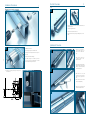
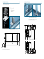
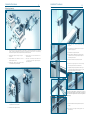
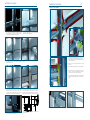
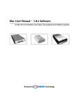
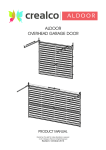
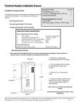
FABRICATION PROCEDURES
WISPECO
REVISION 1.0
Aluminium
INDEX
Index....................................................................... ............................................................................
Legal Disclaimer.............................................................................................................................................
Spigots - Pre-Installation Procedures....................................................................... ............................................................................
Sill - Pre-Site....................................................................... ............................................................................
Sill Installation.............................................................................................................................................
Top & Bottom Mullion Bracket Assembly....................................................................... ............................................................................
Mullion Assembly....................................................................... ............................................................................
Mullion Jig Spigot Operation/Assembly.............................................................................................................................................
Transom Assembly....................................................................... ............................................................................
Glazing....................................................................... ............................................................................
Gasket Assembly/Transom Clip-On Covers.............................................................................................................................................
i
i
1
2
2
3
4
5
6
7
8
crealco
creative aluminium
FAÇADE
60
CURTAIN WALL
FAÇADE 60
AAMSA
A4 RATING
CURTAIN WALL
LEGAL DISCLAIMER
General Documentation Disclaimer
This manual is intended as a manufacturing and installation advisory document.
For correct specifications, sizing of profiles and structural information please consult
the StarFront Application. If the information you require is not available through the
StarFront Application, please contact a Wispeco Technical Representative before proceeding.
It is advisable to have all sizing and performance criteria checked by a qualified structural
engineer to ensure that all performance and compliance will be met.
All information, recommendations or advice contained in this documentation is given in
good faith to the best of Wispeco’s knowledge and is based on current procedures in effect.
Since the actual use of this documentation by the user is beyond the control of Wispeco, such
use is within the exclusive responsibility of the user. Wispeco cannot be held responsible for
any loss incurred through incorrect or faulty use of this documentation. Training of Wispeco
systems is important for ensuring correct procedures in the manufacturing of products.
The use of non-specified hardware or incorrect mechanical fasteners can
adversely affect the mechanical and weathering performance of the
system and we strongly advise against deviations. A Wispeco Consultant
can advise you of any hardware issues and limitations with regard to this
system.
The use of anti-magnetic stainless steel screws and aluminium pop rivets
is recommended to reduce galvanic corrosion in harsh environments.
Fixing lugs on frames must be positioned as per the user manual and
used in accordance to the AAMSA specifications. When profiles are
screwed together the screw centrers must also be according to the user
manual or as specified by an engineer.
All glass used within Wispeco products must comply with SAGGA
regulations. Laminated glass must not stand in water.
Great care has been taken to ensure that the information provided is correct.
Ensure that you have the latest available manual. The revision number and date can be
checked on the latest StarFront version.
Wispeco will accept no responsibility for any errors and/or omissions, which may have
inadvertently occurred.
This Guide may be reproduced in whole or in part in any form or by any means provided the
reproduction or transmission acknowledges the origin, revision number and copyright date.
Specifications concerning products and applications
This manual is based on standard configurations only. As there are many configurations
not covered in this manual, contact a Wispeco Technical Consultant with regard to a
configuration not represented herein.
AutoDesk drawings (CAD Symbol Library) are available on request and can be issued with
the consent of the Wispeco Technical Department.
All mechanical joints must be sealed with Crealco Silicon. Failure to
correctly seal the joints can affect the performance of the system. Information on joint
sealing can be found in the Cleaning & Maintenance Manual available for download from the
Wispeco website.
All drawings in the Wispeco Documentation are shown NOT to scale are used for
illustrative purposes only. For correct sizing and machining of system profiles refer to the
Wispeco StarFront Aplication.
Wispeco cannot accept responsibility for the use of standard products since Wispeco does
not know where these products are being installed.
The hardware recommended in this documentation is suitable for use in most atmospheric
environments. When hardware is used in severe coastal environments the manufacturer of
the hardware must be consulted.
WISPECO
Aluminium
By continuing to use this documentation you acknowledge that you understand
and accept the legal disclaimer.
Installation Procedures
1
Spigots (Pre-site installion procedure)
Pre-Site Procedure
2
Sill
1
1
1.3
1.2
1.2
1.1
1.3
1.3
1.1
Ensure sill is cut to length and ensure weep holes are machined as per
manual (See page 13).
1.2
Fit Euro butterfy gasket as shown.
1.3
Fit & silicone end caps to both sides of sill.
1.4
Ensure that water can freely fow through drainage holes (no burs or
debris).
1.4
Installation Procedure
1.4
2
30
Sill Installation
1.1
Establish transome centres
1.2
Fit pre-cut spigots using 5.5 x 70 St. St. Tek screws.
1.3
Ensure spigots are correctly positioned on the V-groove of
the mullion.
1.4
Ensure correct orientation of the Spigot
2
3
2.1
Place the sill into position on
site as required. Ensure sill is
level and free of debris before
fxing.
3.1
Ensure silicone is placed over
all fxings to ensure no water
ingress under the sill.
4.1
Seal the entire sill perimeter with the
appropriate silicone sealant, paying
attention to all joints and especially
where the sill terminates.
5.1
Where sills need to be joined
together, care must to be taken to
keep them frmly together while
fxing.
5.2
Ensure that both sill ends receive
silicone to seal appropriately.
6.1
Ensure proper care is taken to seal
between the end caps & structue.
2.1
3.1
20
20
30
Note: Fasten the spigot to the mullion using the open
port as this will allow minor adjustments to be made
before complete fxation using the closed port.
Ensure the correct placing of the spigot , especially for the
bottom transome.
4
3
20
20
3.1
30
1.3
5
6
6.1
30
5.2
5.1
Installation Procedure
3
Installation Procedure
4
Mullion
Mullion Brackets (top & bottom)
1
Bracket Assembly
B
A.
Base Plate
B.
Expansion Profle (top & bottom)
D
C
Pressure plate screws
D
D.
Anchors as specifed by engineer
1.2
1.2
1.1
1
A
1.1
Position mullions over sill as required & place into position. Ensure
expansion profle with base plate is ftted into mullions (top &
bottom) prior to positioning mullions over sill .
1.2
Ensure the gap between the top of the mullions & soft is at least
35 mm to accept the compensating angle.
1.3
Mullions should be approximatley 1 mm of the sill.
C
The Mullion Bracket allows for adjustment of the mullion once
the holes and fxation is in place.
11
1.1
14
21
35
35
14
D
2.1
100 mm Mullion
160 mm Mullion
190 mm Mullion
The bottom & top base plates can now be fxed with the
appropiate fxings to the foor & roof slab after checking for
correct mullion centres & levelness.
10
90
150
180
30
16
Note the correct positioning of the sill in relation to the mullions.
14
1.1
Installation Procedures
5
Installation Procedures
6
Transome
Mullion Jig Assembly
1
1
1.5
1.4
1.1
1.2
1.3
1.1
1.2
2
1.
The Spigot Clamp is a clamping and alignment tool which allows for on-site placement and alignment of the spigots to the
mullions. The magnetic faceplate allows for the integration of laser levelling from one mullion to the next, or for spirit levelling
while the mullion is being afxed. The rapid clamps allow for quick placement and rapid release.
1.1
Alignment Block - Alignment of the spigot to the v-groove
of the mullion
1.4
Extension Rods - The rods come in diferent sizes for the
diferent mullion sizes.
1.2
Magnetic Attachment Face - Attachment face for Levels
and laser alignment accessories
1.5
Rear Clamp - The rear clamp is a quick release connector
to connect two spigot clamps together, ensuring that
they are both alighned.
1.3
Clamping Block - Clamps the spigot in place and ensures
no movement when screwing in the TEK Screws
2
1.1
Ensure spigots
transomes.
are
correctly
positioned
before
ftting
1.2
The transomes should be ftted with the transome end caps &
appropiate pvc glazing spacer.
2.1
Slide transomes over spigots until frmly located.
2.2
Ensure compression on Transome End Cap is sufcient to ensure a
consistent seal. If there is not enough compression the system will
allow water ingress into the joint.
2.3
Apply Silicone to Transome End Cap if the joint is in question.
3.1
Fix transomes to spigots using No. 6.3 x 20 St. St. self drilling
tek screws. ((Holes must be 20 mm from transome ends)
4.
Fit appropiate pre-cut glass support profles as required for single
or double glazing glass with glass support blocks. The glass
supports must be min 100mm from edge of transome.
4
2.2
3
3.1
4
2.1
B
NOTE:
The glass setting blocks must be a minimum of 27 mm long for a
square metre of glass. Between 1 & 2 sq/m glass, the setting block to
be cut to 54 mm, & for glass between 2 & 3 sq/m, the setting blocks to
be 81 mm long.
5.1
5
5.2
2.1. The Spigot Clamp is pre-loaded with a spigot and placed
in the gasket plate on the front of the mullion.
5.1
5.1
5.2
2.2. The Rear plates connect using the two clamps
5.1
Ensure for each transome that that the gaskets are cut & positioned
5.2
correctly.
Join Gaskets as shown with vulcanising glue
applied to the ends. (See Pad Gasket Detail on next page)
Note: See diagram for correct ftting & vulcanising gaskets to the
transome end caps.
Installation Procedures
7
Installation Procedures
Glazing
8
Transome Pad Gaskets
1
2
1
1.1
2.1
1.1
1.1
1.3
1.1
1.1
2
1.1. Before the ftting of glass, it is recommemded that petrolleum 2.1. The glazing panels can now be placed into the openings. Ensure
jelly is applied to both the front and rear gaskets. This allows
care is taken to position glass correctly & squarely within each
for easier positioning of the glass in the curtain wall opening
opening & onto the glass setting blocks.
as well as allows glass to seat better onto the gaskets.
3
2.2
1.2
4
3.1
2.1
1.1
3.1
1.1. Before ftting the gaskets, ensure that the channel which house
the gaskets are clean. Ensure that the gaskets are cut an extra 3
mm on each end, and correctly inserted into the gasket channel of
the mullions and transomes.
2
3.1. Once glass is in place, the vertical pressure plates can
4.1
be positioned over the pvc spacer. Ensure the appropiate
gaskets have been inserted.
Fix vertical pressure plates using correct screws with a torque
of 3.2 nm.
1.2. Ensure that the ends are properly cleaned and free from any
debris or oils
2.2
5
6
1.3
2.1
Test the joint before applying the glue, do not stretch the gasket
2.1. Butt the transome gasket to the corresponding profle on the
gasket pad. Place one drop of 3M Vulanising Glue into the but
joint and hold in place until the glue is properly bonded.
2.2. Place the mullion gasket against the side wall of the gasket pad
profle, ensure the mullion gasket can tuck in under the transome
end cap.
5.1. Once the vertical pressure plates are fxed, the horizontal 6.1.
pressure plates can be fxed into place, remember to allow
2 mm gap between horizontal pressure plates & vertical
pressure plates as the vertical covers will not clip on properly.
The vertical covers can now be clipped in over the pressure plates,
followed by the transome covers. Remember to position the
horizontal covers correctly with the weep holes on the underside.
Always ensure that the vertical covers are ftted past the transomes.
3
B
35
A
B
11
14
7.1
NOTE: Very important to silicone seal along the entire length of the
sill once the bottom transome has been ftted.
8.1. Before ftting the top row of glass panels, the 50 x 50 x 6 comp.
angle needs to be ftted.
A.
Insert the Transome Clip end cap into the Transome clip-on cover.
B.
Insert the transome Clip-on cover into the rear transome assembly.