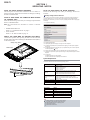
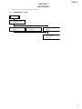
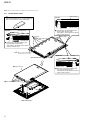
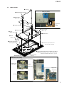
1
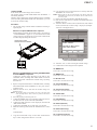
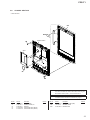
PRS-T1 SERVICE MANUAL US Model Canadian Model AEP Model UK Model Ver. 1.0 2011.09 Note: Be sure to keep your PC used for service and checking of this unit always updated with the latest version of your anti-virus software. In case a virus affected unit was found during service, contact your Service Headquarters. Mass Model name SPECIFICATIONS Supported File Types Approximately 168 g (5.9 oz.) PRS-T1 The following files can be managed on the Reader software and transferred to the Reader device. However, depending on the file size and format, it may not be possible to view/display/play some data. Display Power source Built-in rechargeable battery: 3.7 V DC, 1000mAh USB powered from a computer or the optional AC Adapter PRSA-AC10/PRSA-AC1A (sold separately) via the supplied USB cable. Battery life (continuous page turn) Maximum Battery: Approximately 14,000 continuous page turns when reading only.* * Measured using a text based content in ePub format and a fully charged battery, consecutive pageturns at approximately one second per page under the recommended operating temperature. Actual battery life may vary based on usage patterns and individual device. Charging time Computer-based charging: Approximately 2.5 hours AC Adapter PRSA-AC10/PRSA-AC1A (sold separately)-based charging: Approximately 2 hours Internal Memory Capacity (for data storage) Approximately 1.4 GB after initial setting. Depending on size of pre-loaded excerpts, available memory capacity may vary. 152.4 mm (6 inch) diagonal electrophoretic display 600 × 800 pixels, 16-level grayscale Expansion slots microSD card slot SD cards are made to standards and are commonly used as storage media for portable devices. microSD and microSDHC cards are members of the SD card family. The Reader supports the following card types. microSD and microSDHC cards Up to 32 GB microSD cards of up to 32 GB has been tested to work with the Reader; however, not all microSD cards are guaranteed to work. Supplied items Operating/Charging temperature 5°C to 35°C (41°F to 95°F) Books Wi-Fi Wireless standards: IEEE 802.11b/g/n compliant Wireless security: WEP (Open System), WEP (Shared Key), WPA-PSK (TKIP), WPA-PSK (AES), WPA2-PSK (TKIP), WPA2-PSK (AES) USB cable × 1 Stylus × 1 Quick Start Guide Dimensions (w/h/d) Approximately 110 × 173 × 8.9 mm (4 3/8 × 6 7/8 × 3/8 inches) EPUB files (.epub) EPUB (OPS version 2.0) supported. PDF files (.pdf) Support is based on the PDF 1.6 specification. Text files (.txt) Audio MP3 files (.mp3) The following specifications Bit rate: 8 to 320 kbps Sampling frequency: 8 to File must be unsecured. AAC files (.mp4, .m4a) Raw AAC is not supported. The following specifications Bit rate: up to 160 kbps Sampling frequency: 8 to File must be unsecured. should be met in order to import an MP3 file: 48 kHz should be met in order to import an AAC file: 48 kHz Pictures JPEG files (.jpg, .jpeg) GIF files (.gif) PNG files (.png) BMP files (.bmp) Note If the size of a picture that you transferred with the Reader software is too large, a thumbnail may not be created on the Reader and the picture may not be displayed in the [Pictures] content list. In this case, delete the picture via the Reader software. For an animated GIF file, only the first frame will be shown. Sony, the Sony logo, “Reader”, “BBeB” and their logos are either trademarks or registered trademarks of Sony Corporation. EPUB is a registered trademark of the IDPF. Frutiger, Univers, Helvetica and Palatino are trademarks of Linotype Corp. registered in the United States Patent and Trademark Office and may be registered in certain jurisdictions in the name of Linotype Corp. or its licensee Linotype GmbH. Bitstream is a registered trademark, and Dutch, Font Fusion, and Swiss are trademarks, of Bitstream Inc. Microsoft, Windows, Windows Vista and Windows Media are trademarks or registered trademarks of Microsoft Corporation in the United States and / or other countries. Macintosh and Mac OS are trademarks of Apple Inc., registered in the U.S. and other countries. This PRS-T1 contains Adobe® Reader® Mobile software under license from Adobe Systems Incorporated, Copyright © 1995-2011 Adobe Systems Incorporated. All rights reserved. Adobe and Reader are trademarks of Adobe Systems Incorporated. MPEG Layer-3 audio coding technology and patents licensed from Fraunhofer IIS and Thomson. This product includes software developed by the OpenSSL Project for use in the OpenSSL Toolkit. (http://www.openssl.org/) Copyright© 1998-2011 The OpenSSL Project. All rights reserved. This product includes cryptographic software written by Eric Young ([email protected]). This product includes software written by Tim Hudson ([email protected]). For details on OpenSSL License, refer to [End User License Agreement] in [About] at [Settings] on the Reader. Wi-Fi, the Wi-Fi CERTIFIED logo, WPA, WPA2 and Wi-Fi Protected Setup are trademarks or registered trademarks of Wi-Fi Alliance. All other system names and product names appearing in this document are the registered trademarks or trademarks of their respective owners. Further, the trademark ™ and registered trademark ® symbols are not indicated throughout this document. Program © 2011 Sony Corporation Documentation © 2011 Sony Corporation 9-893-299-01 2011I33-1 © 2011.09 Sony Corporation Published by Sony Techno Create Corporation FLEXIBLE CIRCUIT BOARD REPAIRING • Keep the temperature of soldering iron around 270 °C during repairing. • Do not touch the soldering iron on the same conductor of the circuit board (within 3 times). • Be careful not to apply force on the conductor when soldering or unsoldering. CAUTION Danger of explosion if battery is incorrectly replaced. Replace only with the same or equivalent type. DIGITAL BOOK READER PRS-T1 SECTION 1 SERVICING NOTES NOTE THE EACH BOARDS REPAIRING The mount parts on each boards installed in this set cannot exchange with single. When the each boards are damaged, exchange the entire mounted board. NOTE OF REPLACING THE WLAN ANTENNA Please do the following work when you exchange WLAN ANTENNA. NOTE OF REPLACING THE COMPLETE MAIN BOARD OR CHASSIS ASSY Please do the following work when you exchange complete MAIN board or CHASSIS ASSY. You can set up a Wi-Fi network connection manually by inputting the required information for connection. Make sure to turn on [Wi-Fi] and tap [Wi-Fi Settings] on the [Wireless Network Settings] screen. Alternatively, you can turn on [Wi-Fi] by tapping the status bar and tapping [WiFi Settings]. Manually setting a Wi-Fi connection 1. Tap [Add Wi-Fi Network]. Note: INK INDICATOR 6inch ELEMENT is included in CHASSIS ASSY. • • REWRITING THE LUT: Refer to “9. Update Waveform” on page 9. Write VCOM: Refer to “14. Write VCOM” on page 11. ABOUT THE LEAD WIRE OF BATTERY ASSY (BAT1) Confirm the operation after pressing the button of the main unit bottom without fail when soldering the BATTERY ASSY (BAT1) to the MAIN board. 2. Tap [Manual Registration]. battery assy (BAT1) 3. Tap the [SSID] input area and type in using the on-screen keyboard. 4. Tap the [Security Method] menu (the default value is [Open]), and then tap the supported security type. 5. Tap the [Wachtwoord] input area and type in your password using the on-screen keyboard, and then tap [Gereed] [Save]. MAIN board 6. Tap the saved network SSID in the [Wi-Fi Networks] list on the [Wi-Fi Settings] screen. 7. If prompted for a password, tap the input area and type in the password using the on-screen keyboard. 8. Tap [Connect]. The Reader connects to the Wi-Fi network. The Wi-Fi connection status is displayed in the status bar. soldering System Requirements The Reader software will work with the following operating systems. RESET button Operating System Details Microsoft Windows 7 (32/64bit) Windows 7 Starter Windows 7 Home Basic Windows 7 Home Premium Windows 7 Professional Windows 7 Ultimate Microsoft Windows Vista (32/64-bit) Windows Vista Home Basic with Service Pack 2 or later Windows Vista Home Premium with Service Pack 2 or later Windows Vista Business with Service Pack 2 or later Windows Vista Ultimate with Service Pack 2 or later Microsoft Windows XP (32bit only) Windows XP Home Edition with Service Pack 3 or later Windows XP Professional with Service Pack 3 or later Windows XP Media Center Edition 2004 & 2005 with Service Pack 3 or later Mac OS X 10.7 (64-bit only) Mac OS X version 10.7 or later Mac OS X 10.6 (32/64-bit) Mac OS X version 10.6.6 Mac OS X 10.5 (32-bit only) Mac OS X version 10.5.8 The Reader software also requires at minimum the following computing environment. Requirement Details CPU 1 GHz Intel processor RAM 512 MB Free space on hard disc 250 MB or more* Screen 1,024 x 768 display resolution with 24-bit color Network Broadband internet connection * Depending on the content amount, more space may be required. Note The Reader software is not supported with the following: An operating system other than those listed above A personally built computer or operating system A multi-boot environment A multi-monitor environment 2 PRS-T1 SECTION 2 DISASSEMBLY • This set can be disassembled in the order shown below. 2-1. DISASSEMBLY FLOW SET 2-2. CASE REAR ASSY (Page 4) 2-3. MAIN BOARD (Page 5) 2-4. CASE FRONT ASSY (Page 6) 2-5. BATTERY ASSY (BAT1) (Page 7) 2-6. CHASSIS ASSY (IIE1), JACK BOARD (Page 7) 3 PRS-T1 Note: Follow the disassembly procedure in the numerical order given. 2-2. CASE REAR ASSY JIG When disassembling the set, use the following jig. Part No. 9-913-402-33 Tool for Disassembly Top side: case rear assy case front assy Left side: 1 Insert the jig in the gap between case rear assy and case front assy. Then slide it to arrow direction to remove claws of case rear assy. case rear assy 4 five claws 2 four claws case front assy 3 Insert the jig in the gap between case rear assy and case front assy. Then slide it to arrow direction to remove claws of case rear assy. Note: Please spread a sheet under a unit not to injure case front. Right side: – Rear bottom view – 7 case rear assy case rear assy 4 five claws case front assy 3 Insert the jig in the gap between case rear assy and case front assy. Then slide it to arrow direction to remove claws of case rear assy. 5 five claws 6 – Rear bottom view – 4 PRS-T1 2-3. MAIN BOARD 1 sheet AL %DWWHU\ DVV\ %$7 ZLUH VHWWLQJ battery assy (BAT1) 2 WLAN antenna connector 8 three screws (M1.4 u L2) copper leaf (PWB) 9 copper leaf (PWB) MAIN board 8 screw (M1.4 u L2) white red black 8 seven screws (M1.4 u L2) 3 sheet (cable) 0 MAIN board 7 screw (M1.4 u 1.6) 6 element INK indicator flexible printed board Note 1: Please spread a sheet under a unit not to injure case front. 4 Remove three solders of wire of battery assy (BAT1). Note 2: When soldering, refer to “ABOUT THE LEAD WIRE OF BATTERY ASSY (BAT1)” (page 2). – 5HDU ERWWRP YLHZ – 5 FPC M-J5047 (FPC1) :/$N DQWHQQD ZLUH VHWWLQJ WLAN antenna conductor part (without film) sheet AL MAIN board MAIN board – OK – film part – NG – 5 PRS-T1 2-4. CASE FRONT ASSY 1 sheet AL 2 WLAN antenna connector 3 three tapping screws (P2) 3 three tapping screws (P2) 7 5 Remove six claws in order of the arrow B. Note: Please spread a sheet under a unit not to injure case front. B C 8 case front assy 4 Remove five claws in order of the arrow A. A – Rear bottom view – 6 Remove six claws in order of the arrow C. :/$N aQteQQa wire VettiQJ WLAN antenna conductor part (without film) sheet AL MAIN board MAIN board – OK – film part – NG – 6 PRS-T1 2-5. BATTERY ASSY (BAT1) %atter\ aVV\ %$7 wire VettiQJ battery assy (BAT1) 1 sheet (cable) 3 battery assy (BAT1) 4 Remove three solders of wire of battery assy (BAT1). Note 2: When soldering, refer to “ABOUT THE LEAD WIRE OF BATTERY ASSY (BAT1)” (page 2). copper leaf (PWB) white MAIN board red black Note 1: Please spread a sheet under a unit not to injure case front. – Rear bottom view – 2-6. CHASSIS ASSY (IIE1), JACK BOARD 1 three screws (PWH) 2 light guide 1 three screws (PWH) 3 three screws (M1.4 u L2) 8 JACK board 7 FPC M-J5047 (FPC1) Note: When installing the FPC M-J5047 (FPC1), confirm the inserted direction. FPC M-J5047 (FPC1) JACK board convex part slit 5 Pull out FPC M-J5047 (FPC1) from the slit. 4 claw 6 chassis assy (IIE1) – Front bottom view – 7 PRS-T1 SECTION 3 TEST MODE PREPARATION OF THE TEST MODE Prepare the following before executing the test mode. • • • PC USB cable for PC connection (MICRO B) File for the test mode Note: Confirm the method of obtaining the file for test mode to each service headquarters. HOW TO ENTER THE TEST MODE Procedure: 1. Press the [1] key to turn the power on. 2. Confirm the HOME menu was completely displayed, and connect this unit to PC by the USB cable (MICRO B). 3. Confirm the USB connection screen displayed, and touch the “Data Transfer Mode”. 4. Confirm the “READER” drive of this unit is recognized. 5. Copy the file for the test mode from PC to directly under the “READER” drive of this unit. 6. Remove this unit and USB cable (MICRO B) from PC. 7. Confirm the HOME menu was completely displayed, and press the key as following order. OPERATION OF EACH MODE 1. Test Panel The panel can be checked. Procedure: 1. Touch the “Test Panel” in the test mode menu. 2. The image file is displayed (image files of in the directly as “/ testmode/images/”). The format that can be treated is “.bmp”, “.jpeg” , “.gif” and “.png”. The all image files are transformed into the 600 x 800 size, and the linear interpolation processing of pixel is done. 3. Press the [<]/[>] keys, the image files are chenged. Note: If there are no image files, the screen changes into grayscale color. Press the [<]/[>] keys, the grayscale color changes sequentially as shown in the figure below. > BLACK < > LIGHT GRAY DARK GRAY < > < [>] [ ] [<] [ ] 8. After a while, the test mode menu is displayed, and this unit enters the test mode. 2. Drawing with Points This mode is not used in servicing. @Test Mode Version: X.X.X Target storage: Internal Test Panal Update Waveform IR-LED Level Drawing with Points Reset Device Lock Check 3G Module TP Coordinate Power Off Check User History Test All Key Log Extact 1 Switch ADB Test Battery Life Check Temperature Fake MoAkey Version Confirmation Write VCOM Reboot (Normal) Check Battery WWAN ON Reboot (Recovery) Factory Initialize WWAN OFF Log Extact 2 (Flush) (Screen display) RELEASING THE TEST MODE Procedure: 1. Press the [ ] key, and confirm the HOME menu was completely displayed. 2. Connect this unit to PC by the USB cable (MICRO B). 3. Confirm the USB connection screen displayed, and touch the “Data Transfer Mode”. 4. Confirm the “READER” drive of this unit is recognized. 5. Delete the file for the test mode from directly under the “READER” drive of this unit. 6. Remove this unit and USB cable (MICRO B) from PC. 7. Confirm the HOME menu was completely displayed, and press the key as following order, and confirm that the test mode does not enter. [>] [ ] [<] [ ] 8. Press the [1] key for 5 seconds or more, and touch the “Yes” to turn the power off. Note: Never forget to delete the file for the test mode. 8 Releasing method: Press the [ ] key, return to the test mode menu. 3. TP Coordinate This mode is not used in servicing. 4. Test All Key This mode is not used in servicing. 5. Test Battery Life This mode is not used in servicing. 6. Version confirmation This mode is not used in servicing. 7. Check Battery This mode is not used in servicing. > WHITE < PRS-T1 8. Factory Initialize This unit can be returned to the state of the factory shipment. Procedure: 1. Touch the “Factory Initialize” in the test mode menu. Factory Initialize 9. Update Waveform LUT rewriting and the LUT update confirmation can be executed. As for INK INDICATOR 6inch ELEMENT, the parameter that rewrites the screen of each FPL lot number and TFT vender are different. This parameter is called LUT (Look Up Table). Therefor, you need to rewrite the LUT when replacing the complete MAIN board or CHASSIS ASSY (including INK INDICATOR 6inch ELEMENT). However, rewriting is not required if the FPL lot number and TFT vender are the same. Note 1: LUT is written in IC2001 on the MAIN board. Would you like to execute ‘Factory Initialize’ ? Yes No (Screen display) Procedure: 1. The LUT confirm method is different according to replaced parts. When the complete MAIN board is replaced: Disassemble this unit until the FPL lot number and TFT vender are seen (Refer to “2. DISASSEMBLY” (pages 3 to 7)), and confirm the FPL lot number and TFT vender referring to the figure below. Record the confirmed the FPL lot number and TFT vender by taking the memo etc.. Flexible board of INK INDICATOR 6inch ELEMENT 2. When “Yes” is touched, the deletion of all histories and reset of all settings are executed, then this unit turn the power off. ED060SCE(LF)C1 FME60B5060(E120) E4KR28C01L5V00111AT TFT vender FPL lot number When the CHASSIS ASSY (including INK INDICATOR 6inch ELEMENT) is replaced: Confirm the FPL lot number and TFT vender described on the label of new CHASSIS ASSY (including INK INDICATOR 6inch ELEMENT). Record the confirmed the FPL lot number and TFT vender by taking the memo etc.. 2. Replace complete MAIN board or CHASSIS ASSY (including INK INDICATOR 6inch ELEMENT) for new parts, and assemble this unit. 3. Confirm the following data to the service headquarters. • WF file corresponding to the recorded FPL lot number and TFT vender • WF file translation tool (wwv_parser.exe) 4. Copy the file and the tool obtained in step 3 to directly under the C drive of PC (Windows XP or more is recommended). 9 PRS-T1 5. Start the command prompt, and execute the following commands. “c:\wwv_parser.exe -o c:\lut.bin c:\” + “(file name of WF file)” Example of inputting command: c:\wwv_parser.exe -o c:\lut.bin c:\V220_C036_60_WQ0303_ED060SC7C1_BTC.wbf Input the provided WF file name to this part. “c:\wwv_parser.exe -o c:\lut.bin c:\” is invariable. “wwv_parser.exe” is a name of provided WF file translation tool. “lut.bin” is a file converted into the form that can be stored in the device. 6. 7. 8. 9. 10. 10. Reset Device Lock When the Device Lock is effective, it can be released. Note: When this mode is performed, it is necessary to reboot this unit and to validate the settings. Touch the “Reboot (Normal)” in the test mode menu. Procedure: 1. Touch the “Reset Device Lock” in the test mode menu. 2. When the Device Lock is effective, the following screen is displayed. Touch the “Yes”, the Device Lock becomes invalid. It returns to the test mode menu when “No” is touched. @Test Mode Version: X.X.X Target storage: Internal The “lut.bin” file is generated to directly under the C drive. Press the [1] key to turn the power on. Confirm the HOME menu was completely displayed, and connect this unit to PC by the USB cable (MICRO B). Confirm the USB connection screen displayed, and touch the “Data Transfer Mode”. Confirm the “READER” drive of this unit is recognized. Make the following folder under the “READER” drive of this unit. Test Panal Update Waveform IR-LED Level Drawing with Points Reset Device Lock Check 3G Module TP Coordinate Power Off Reset Device Lock Check User History Status: Locked. Test All Key Log Extact 1 Switch ADB Would you like to unlock? Check Test Battery Life Fake MoAkey Temperature Version ConfirmationYes Write VCOM NoReboot (Normal) Check Battery WWAN ON Reboot (Recovery) Factory Initialize WWAN OFF Log Extact 2 (Flush) /testmode/data/ 11. Copy the “lut.bin” file made in step 5 to the “data” folder made in step 10. 12. Copy the file for the test mode from PC to directly under the “READER” drive of this unit. Note 2: When the file for the test mode already exists directly under the “READER” drive of this unit, the file for the test mode need not be newly copied. 13. Remove this unit and USB cable (MICRO B) from PC. 14. Enter the test mode (Refer to “HOW TO ENTER THE TEST MODE” (page 8)). 15. Touch the “Update Waveform” in the test mode menu, and confirm current (unrenewed) LUT version is displayed (Example: “0000112344567789” in the figure below). Version: X.X.X Target storage: Internal Test Panal Update Waveform IR-LED Level Drawing with Points Reset Device Lock Check 3G Module TP Coordinate Power Off Update waveform Check User History Current: Test 0000112344567789 All Key Log Extact 1 Test Battery Life @Test Mode Version: X.X.X Target storage: Internal Test Panal Update Waveform IR-LED Level Drawing with Points Reset Device Lock Check 3G Module TP Coordinate Power Off Reset Device Lock Check User History Log Extact 1 Switch ADB Test Battery Life Check OK Temperature Fake MoAkey Version Confirmation Write VCOM Reboot (Normal) Check Battery WWAN ON Reboot (Recovery) Factory Initialize WWAN OFF Log Extact 2 (Flush) (Screen display) Check Version Confirmation Write VCOM Check Battery WWAN ON Reboot (Recovery) Factory Initialize WWAN OFF Log Extact 2 (Flush) Yes Test All Key Switch ADB Would you Temperature like to update?Fake MoAkey Reboot (Normal) No (Example of displaying current (unrenewed) LUT version) 10 When the Device Lock is not effective, the following screen is displayed. Touch the “OK”, return to the test mode menu. Status: Unlocked. @Test Mode 16. 17. 18. 19. (Screen display) Touch the “Yes”, it starts rewriting LUT version. After about 10 seconds, screen changes into all white. Press [RESET] key and reboot this unit. Enter the test mode again, and confirm LUT version has been updated. 11. Power Off This mode is not used in servicing. 12. Log Extract 1 This mode is not used in servicing. 13. Check Temperature This mode is not used in servicing. PRS-T1 14. Write VCOM In this mode, the VCOM voltage can be rewritten. The VCOM voltage for INK INDICATOR 6inch ELEMENT is individually different. Therefor, when replacing the complete MAIN board or CHASSIS ASSY (including INK INDICATOR 6inch ELEMENT) you need to rewrite the VCOM voltage. Procedure: 1. The VCOM voltage confirm method is different according to replaced parts. When the complete MAIN board is replaced: Disassemble this unit until the VCOM voltage is seen (Refer to “2. DISASSEMBLY” (pages 3 to 7)), and confirm the VCOM voltage referring to the figure below. Record the confirmed the VCOM voltage by taking the memo etc.. Flexible board of INK INDICATOR 6inch ELEMENT 10. Copy the file for the test mode from PC to directly under the “READER” drive of this unit. Note 2: When the file for the test mode already exists directly under the “READER” drive of this unit, the file for the test mode need not be newly copied. 11. Remove this unit and USB cable (MICRO B) from PC. 12. Enter the test mode (Refer to “HOW TO ENTER THE TEST MODE” (page 8)). 13. Touch the “Write VCOM” in the test mode menu, and confirm current (unrenewed) VCOM voltage is displayed (Example: -1854 mV in the figure below). @Test Mode Version: X.X.X Target storage: Internal Test Panal Update Waveform IR-LED Level Drawing with Points Reset Device Lock Check 3G Module TP Coordinate Power Off Write VCOM Check User History Status: 1854mV Test All Key Log Extact 1 Switch ADB Whould you like to write? Check Fake MoAkey New value:Temperature 2030mV Test Battery Life Version Confirmation Write VCOM Check Battery WWAN ON Reboot (Recovery) Factory Initialize WWAN OFF Log Extact 2 (Flush) Yes Reboot (Normal) No (Example of displaying current (unrenewed) VCOM voltage) -2.03 14. Touch the “Yes”, it starts rewriting the VCOM voltage. 15. Confirm the VCOM voltage has been updated. VCOM voltage When the CHASSIS ASSY (including INK INDICATOR 6inch ELEMENT) is replaced: Confirm the VCOM voltage described on the label of new CHASSIS ASSY (including INK INDICATOR 6inch ELEMENT). Record the confirmed the VCOM voltage by taking the memo etc.. 2. Replace complete MAIN board or CHASSIS ASSY (including INK INDICATOR 6inch ELEMENT) for new parts, and assemble this unit. 3. Make the text file on PC, and write the VCOM voltage confirmed in step 1. Note 1: The VCOM voltage is described by the unit of mV that omits minus (Example: Write “2030” when it is printed on the label as “–2.03 V”). 4. Press the [1] key to turn the power on. 5. Confirm the HOME menu was completely displayed, and connect this unit to PC by the USB cable (MICRO B). 6. Confirm the USB connection screen displayed, and touch the “Data Transfer Mode”. 7. Confirm the “READER” drive of this unit is recognized. 8. Make the following folder under the “READER” drive of this unit. 15. WWAN ON This mode is not used in servicing. 16. WWAN OFF This mode is not used in servicing. 17. IR-LED Level This mode is not used in servicing. 18. Check 3G Module This mode is not used in servicing. 19. Check User History This mode is not used in servicing. 20. Switch ADB This mode is not used in servicing. 21. Fake MoAkey This mode is not used in servicing. 22. Reboot (Normal) This mode is not used in servicing. 23. Reboot (Recovery) This mode is not used in servicing. /testmode/data/ 9. Copy the text file made in step 3 to the “data” folder made in step 8. Then, change the file name to “Vcom.dt”. 24. Log Extact 2 (Flush) This mode is not used in servicing. 11 PRS-T1 SECTION 4 EXPLODED VIEWS Note: • -XX and -X mean standardized parts, so they may have some difference from the original one. • Items marked “*” are not stocked since they are seldom required for routine service. Some delay should be anticipated when ordering these items. 4-1. • The mechanical parts with no reference number in the exploded views are not supplied. • Color Indication of Appearance Parts Example: KNOB, BALANCE (WHITE) . . . (RED) Parts Color Cabinet’s Color CASE REAR SECTION 6 5 4 (RED MODEL) 4 7 (WHITE MODEL) 4 3 3 2 (BLACK MODEL) 3 1 case front, battery section Ref. No. Part No. Description 1 1 1 2 3 4-283-803-01 4-283-803-11 4-283-803-21 4-292-694-01 4-408-115-01 BUTTON POWER (WHITE) BUTTON POWER (BLACK) BUTTON POWER (RED) SHEET (POWER LED) SHEET (4X3), ADHESIVE 4 5 4-283-802-01 4-283-800-01 WINDOW ACCESS COVER SLOT (WHITE) 12 Remark Ref. No. Part No. Description 5 5 6 4-283-800-11 4-283-800-21 4-283-799-01 COVER SLOT (BLACK) COVER SLOT (RED) CASE REAR (WHITE) 6 6 7 4-283-799-11 4-283-799-21 4-411-916-01 CASE REAR (BLACK) CASE REAR (RED) SHEET (CARD LED) (for WHITE) Remark PRS-T1 4-2. CHASSIS SECTION • Rear side view 54 ANT1 53 52 chassis section BAT1 51 52 Note 1: Confirm the operation after pressing the button of the main unit bottom without fail when soldering the BATTERY ASSY (BAT1) to the MAIN board. Note 2: When replacing the WLAN antenna (ANT1), refer to “NOTE OF REPLACING THE WLAN ANTENNA” (page 2). Ref. No. 51 52 53 54 54 Part No. Description 4-287-952-01 3-080-204-11 4-287-942-01 A-1832-979-A A-1833-201-A SHEET (CABLE) SCREW, TAPPING, P2 SHEET AL CASE FRONT ASSY (WHITE) CASE FRONT ASSY (BLACK) Remark Ref. No. 54 ANT1 BAT1 Part No. Description A-1833-206-A 1-754-788-11 A-1832-983-A CASE FRONT ASSY (RED) ANTENNA, WLAN BATTERY ASSY Remark 13 PRS-T1 4-3. ORNAMENT SECTION 107 103 103 108 106 IIE1 105 101 103 FPC1 104 103 102 101 Note: When replacing the MAIN board or CHASSIS ASSY (IIE1), refer to “NOTE OF REPLACING THE COMPLETE MAIN BOARD OR CHASSIS ASSY” (page 2). Ref. No. Part No. Description 101 102 103 104 105 2-587-733-01 4-283-797-01 4-292-680-01 A-1832-986-A X-2582-657-1 SCREW (PWH) LIGHT GUIDE SHAFT (M1.4XL2) JACK BOARD, COMPLETE MAIN BOARD, COMPLETE (for SERVICE) 106 4-264-211-21 SCREW, 0+Z M1.4X1.6 14 Remark Ref. No. 107 108 FPC1 IIE1 Part No. Description Remark 4-287-943-01 4-408-115-01 1-884-637-11 A-1832-982-A LEAF (PWB), COPPER SHEET (4X3), ADHESIVE FPC M-J5047 CHASSIS ASSY (Including INK INDICATOR 6 inch ELEMENT) PRS-T1 SECTION 5 ACCESSORIES Ref. No. Part No. Description 1-839-534-11 4-288-610-12 CABLE, USB (MICRO B) (USB cable) QUICK START GUIDE (PAPER) (ENGLISH, FRENCH) QUICK START GUIDE (PAPER) (GERMAN, DUTCH) (AEP, UK) QUICK START GUIDE (PAPER) (SPANISH, ITALIAN) (AEP, UK) QUICK START GUIDE (PAPER) (FINNISH, SWEDISH) (AEP, UK) 4-288-610-22 4-288-610-32 4-288-610-41 4-288-610-51 X-2582-530-1 Remark QUICK START GUIDE (PAPER) (DANISH, NORWEGIAN) (AEP, UK) STYLUS ASSY (Stylus) 15 PRS-T1 REVISION HISTORY Checking the version allows you to jump to the revised page. Also, clicking the version at the top of the revised page allows you to jump to the next revised page. Ver. Date 1.0 2011.09 Description of Revision New